Embed Size (px)
Citation preview
CNC-IN http://stores.ebay.com.hk/verycnc Email:[email protected] tel:+8613937119428
- 1-
CNC MACH 3 in&out-put port extension board MODIO_I NEW
Features: 1、 it is very easy to setup the extension IO input and output port expecially for the Mach 3 control 2、 12-wires optical isolated input ( 4-wires are high-speed IO can connect the encoder) 3、 12-wires optical isolated output to control the external equipments 4、 The communication port is MODBUS slavestation , 1 RS232 communication port by setting up the jumper , this
RS232 port can be used as RS485 or USB port
CNC-IN http://stores.ebay.com.hk/verycnc Email:[email protected] tel:+8613937119428
- 2-
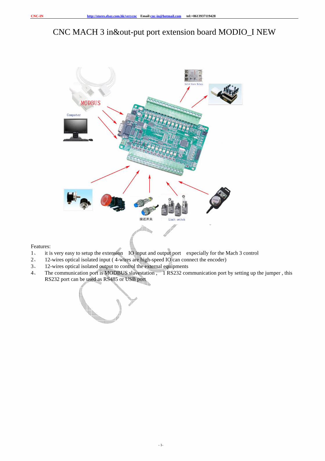
Connection port definition:
Jumper :
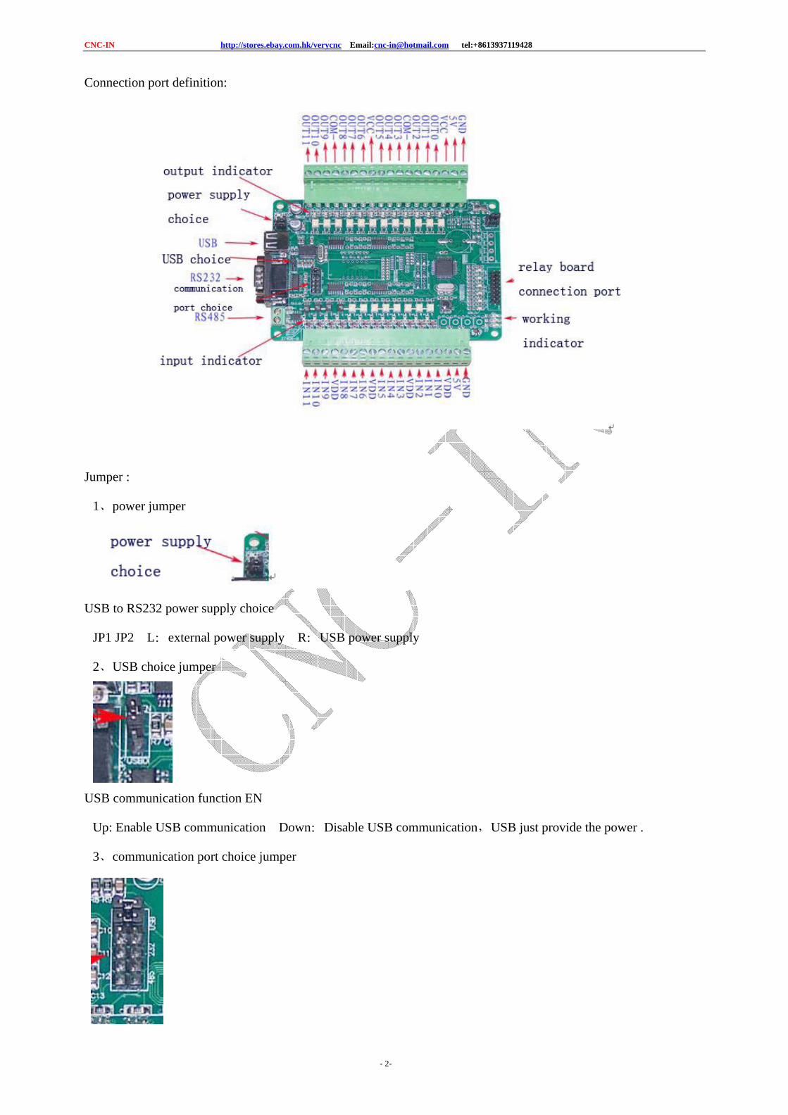
1、power jumper
USB to RS232 power supply choice
JP1 JP2 L:external power supply R:USB power supply
2、USB choice jumper
USB communication function EN
Up: Enable USB communication Down:Disable USB communication,USB just provide the power .
3、communication port choice jumper
CNC-IN http://stores.ebay.com.hk/verycnc Email:[email protected] tel:+8613937119428
- 3-
USB: use USB communication port
RS232: use RS232 communication port
RS485: use RS485 communication port
4.Communication connecting port
USB connector can supply the power to IO board , it corresponds to the PC communication port N
RS232 connector ,uses DB9 serial port cable to connect the PC , it corresponds to the PC commnunication port
COM0
RS485 connector ,it corresponds to the PC commnunication port COM0
Relay connecting port
IO-PORT can be connected to the relay OI board , to change the output function to Relay
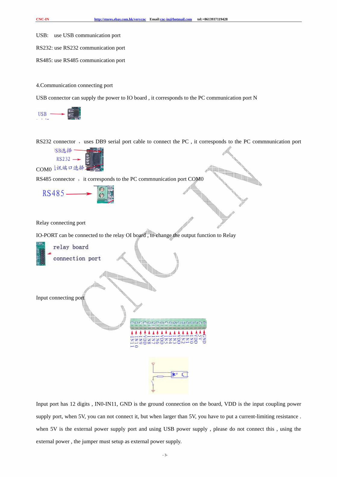
Input connecting port
Input port has 12 digits , IN0-IN11, GND is the ground connection on the board, VDD is the input coupling power
supply port, when 5V, you can not connect it, but when larger than 5V, you have to put a current-limiting resistance .
when 5V is the external power supply port and using USB power supply , please do not connect this , using the
external power , the jumper must setup as external power supply.
CNC-IN http://stores.ebay.com.hk/verycnc Email:[email protected] tel:+8613937119428
- 4-
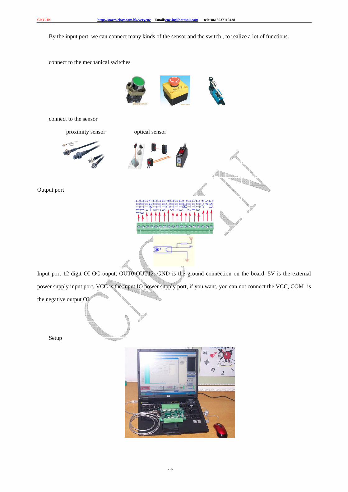
By the input port, we can connect many kinds of the sensor and the switch , to realize a lot of functions.
connect to the mechanical switches
connect to the sensor
proximity sensor optical sensor
Output port
Input port 12-digit OI OC ouput, OUT0-OUT12. GND is the ground connection on the board, 5V is the external
power supply input port, VCC is the input IO power supply port, if you want, you can not connect the VCC, COM- is
the negative output OI.
Setup
CNC-IN http://stores.ebay.com.hk/verycnc Email:[email protected] tel:+8613937119428
- 5-
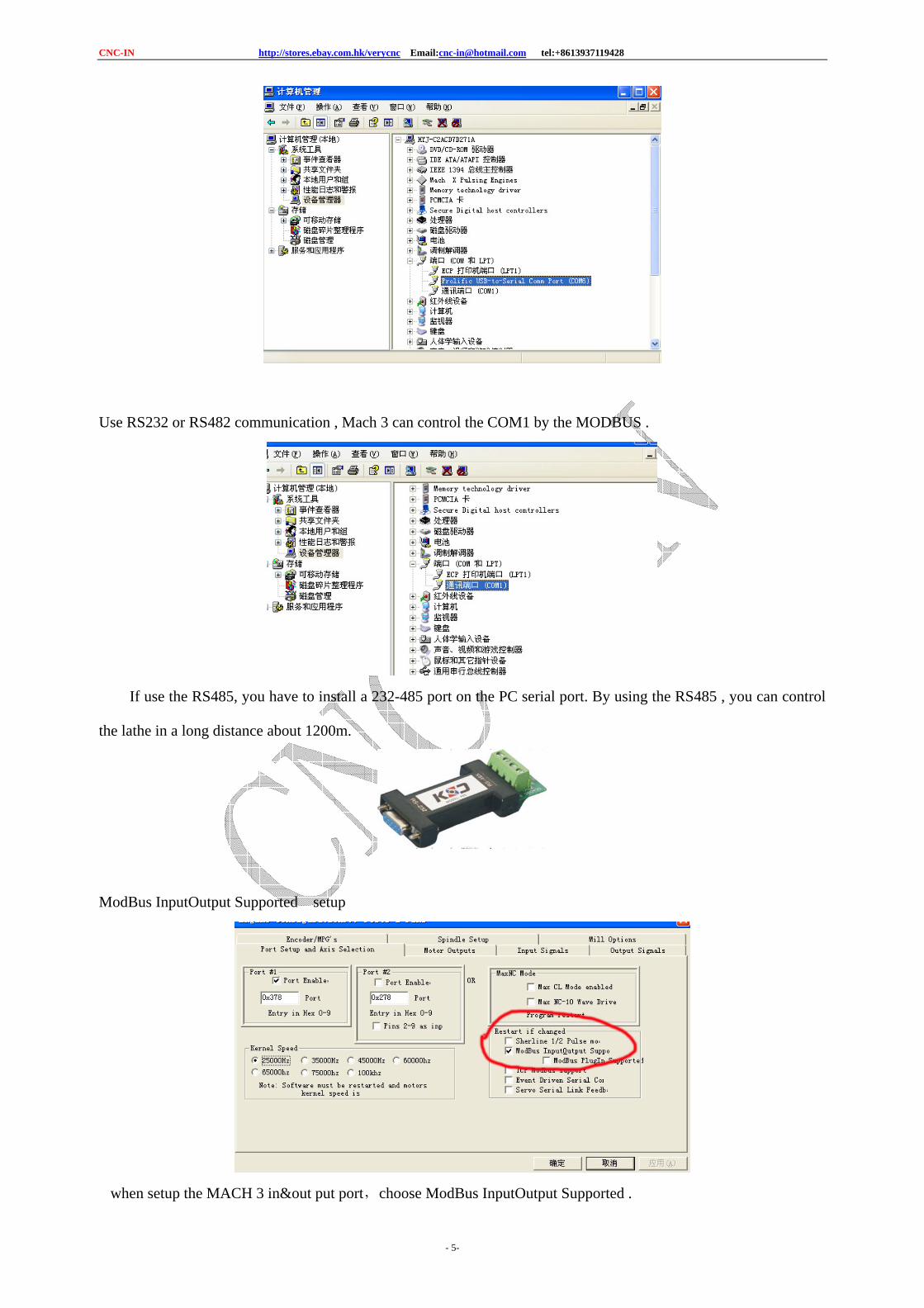
Use RS232 or RS482 communication , Mach 3 can control the COM1 by the MODBUS .
If use the RS485, you have to install a 232-485 port on the PC serial port. By using the RS485 , you can control
the lathe in a long distance about 1200m.
ModBus InputOutput Supported setup
when setup the MACH 3 in&out put port,choose ModBus InputOutput Supported .
CNC-IN http://stores.ebay.com.hk/verycnc Email:[email protected] tel:+8613937119428
- 6-
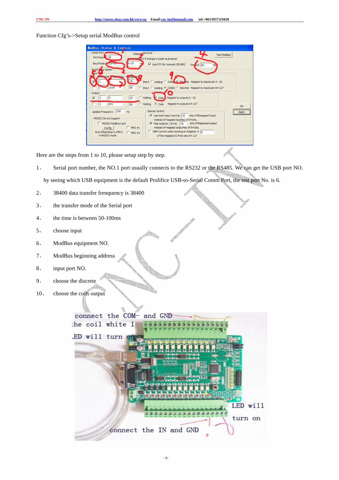
Function Cfg’s->Setup serial ModBus control
Here are the steps from 1 to 10, please setup step by step.
1、 Serial port number, the NO.1 port usually connects to the RS232 or the RS485. We can get the USB port NO.
by seeing which USB equipment is the default Prolifice USB-to-Serial Comm Port, the test port No. is 6.
2、 38400 data transfer frenquency is 38400
3、 the transfer mode of the Serial port
4、 the time is between 50-100ms
5、 choose input
6、 ModBus equipment NO.
7、 ModBus beginning address
8、 input port NO.
9、 choose the discrete
10、 choose the coils output
CNC-IN http://stores.ebay.com.hk/verycnc Email:[email protected] tel:+8613937119428
- 7-
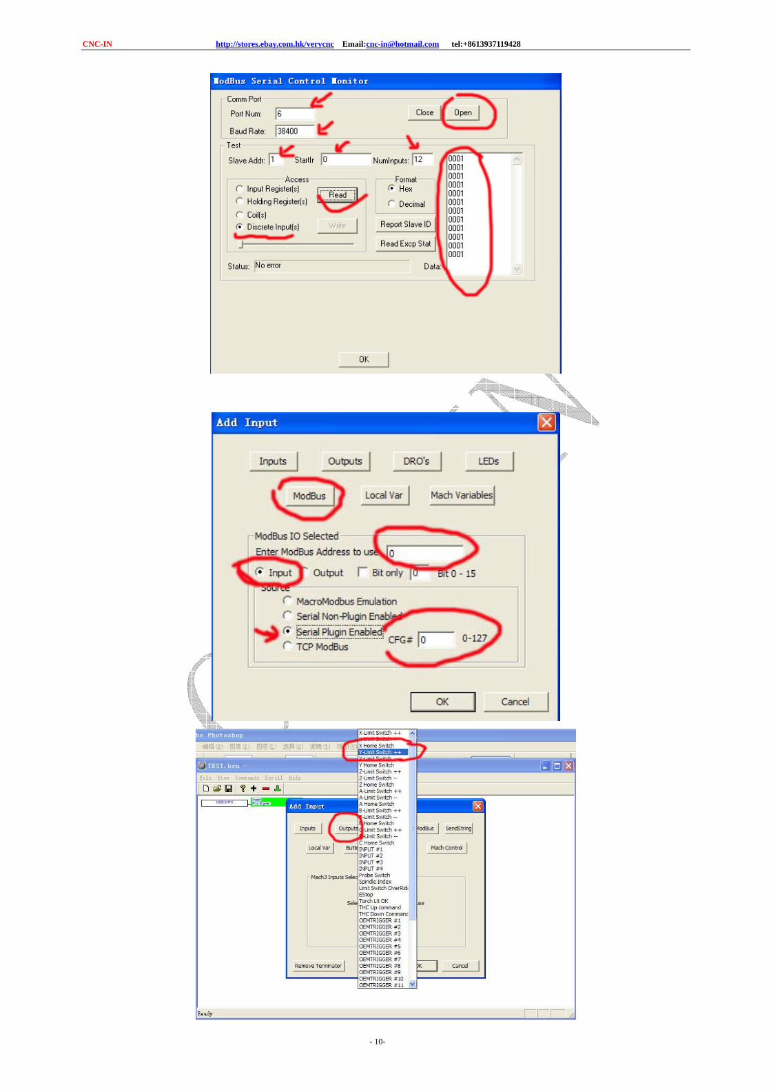
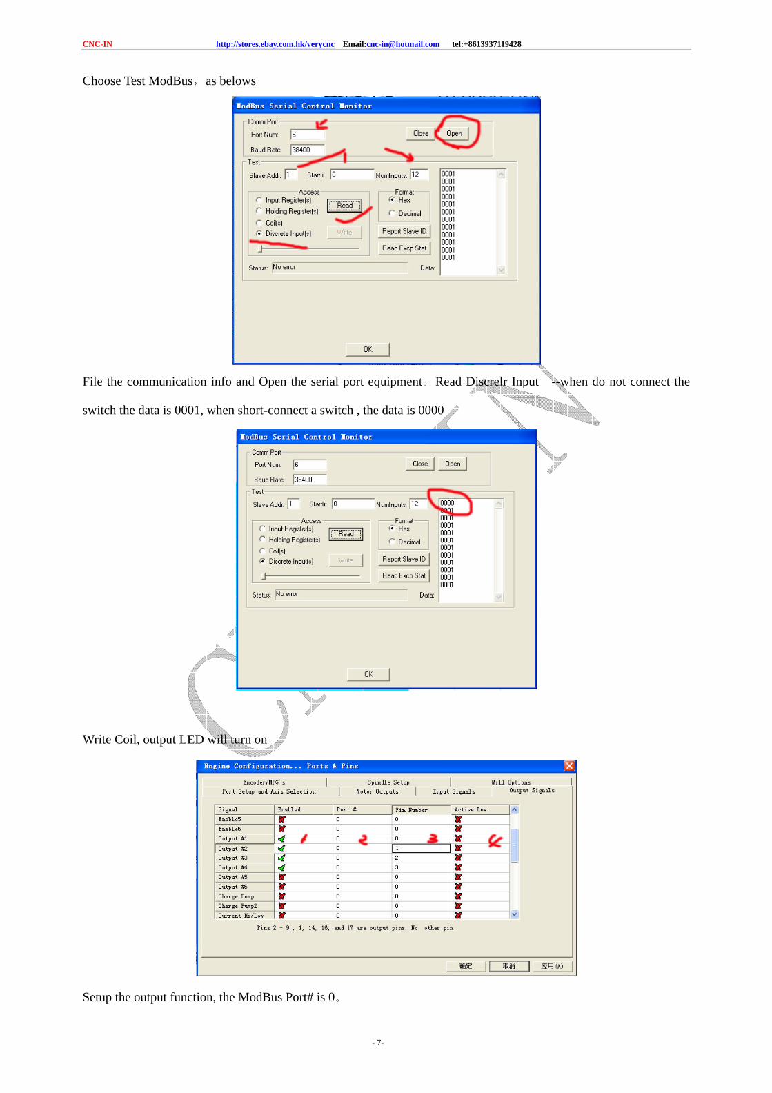
Choose Test ModBus,as belows
File the communication info and Open the serial port equipment。Read Discrelr Input --when do not connect the
switch the data is 0001, when short-connect a switch , the data is 0000
Write Coil, output LED will turn on
Setup the output function, the ModBus Port# is 0。
CNC-IN http://stores.ebay.com.hk/verycnc Email:[email protected] tel:+8613937119428
- 8-
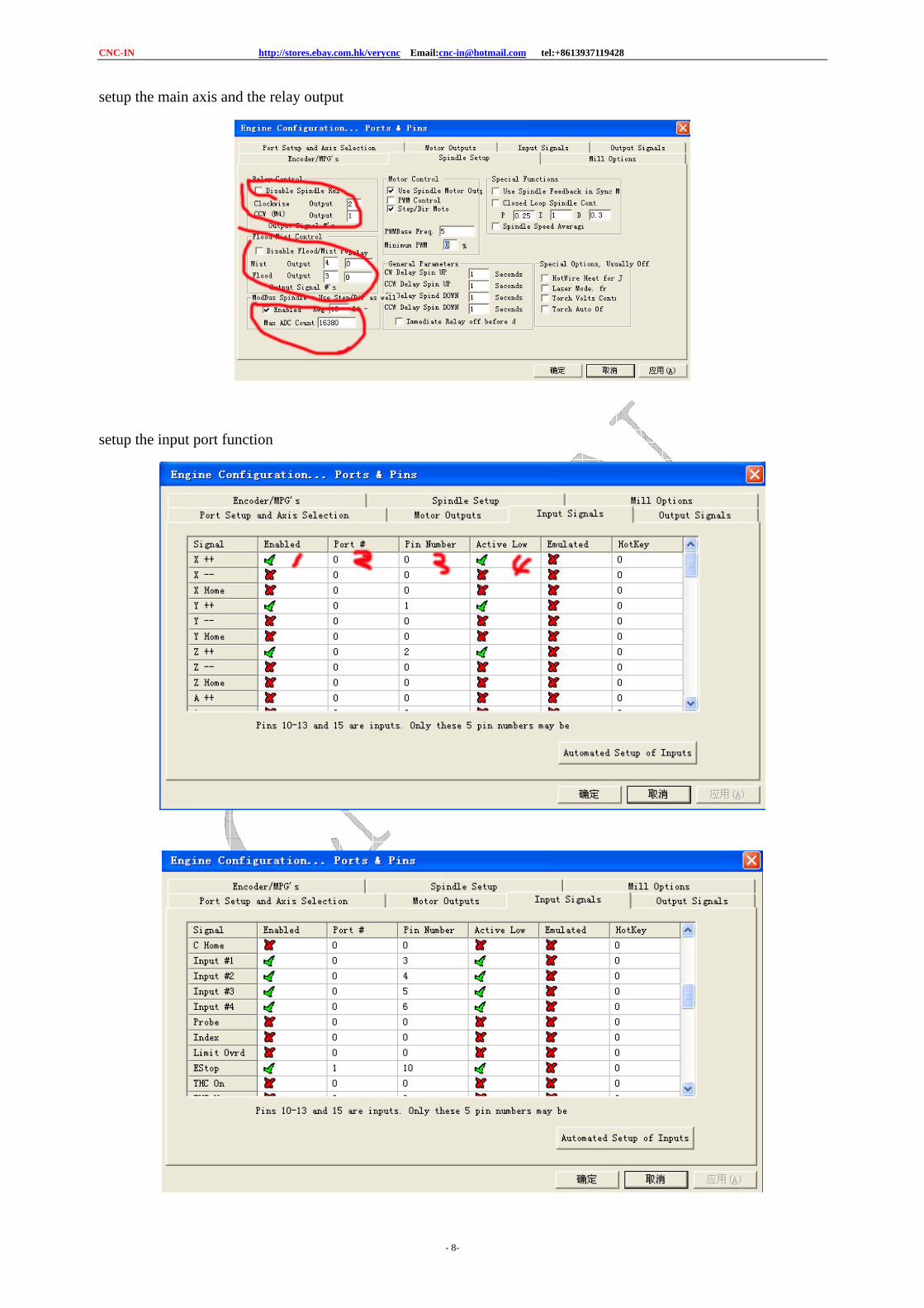
setup the main axis and the relay output
setup the input port function
CNC-IN http://stores.ebay.com.hk/verycnc Email:[email protected] tel:+8613937119428
- 9-
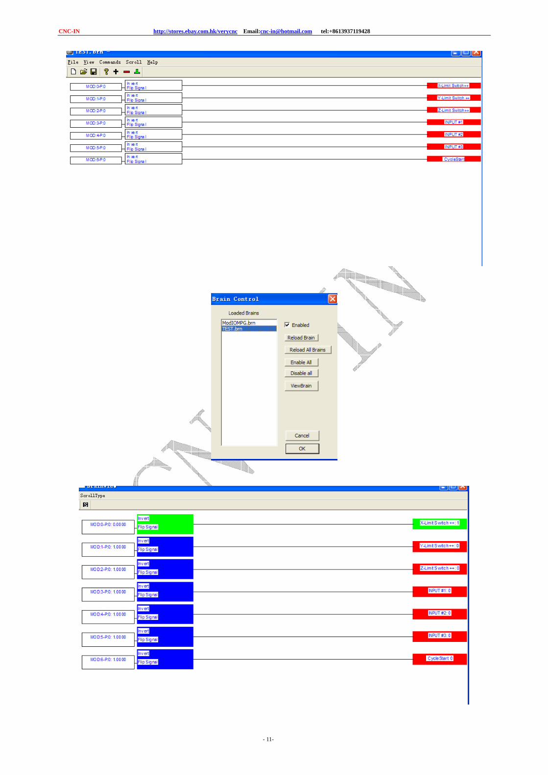
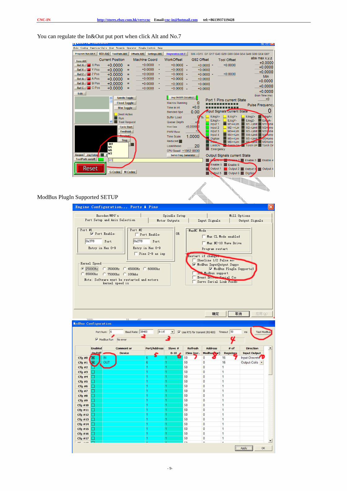
You can regulate the In&Out put port when click Alt and No.7
ModBus PlugIn Supported SETUP