Embed Size (px)
Citation preview
Modification of the Rolling Thin Film Oven
(RTFO) Test for Realistic Short-term Aging of
Asphalt Rubber Binders
M. Zia Alavi, Post-Doc Scholar
Xai Lau, Graduate Student
David Jones, Associate Director
John Harvey, Professor
52nd Petersen Asphalt Research Conference Western Research Institute
July 13-15, 2015 Laramie, Wyoming
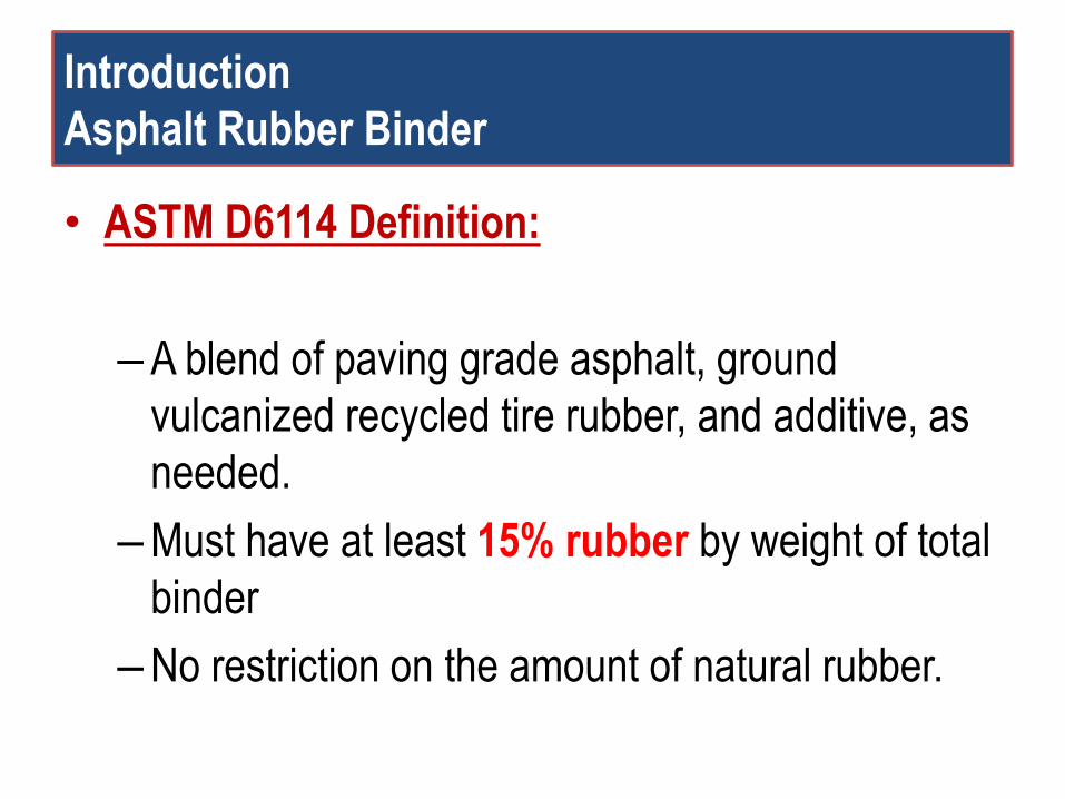
Introduction
Asphalt Rubber Binder
• ASTM D6114 Definition:
–A blend of paving grade asphalt, ground
vulcanized recycled tire rubber, and additive, as
needed.
–Must have at least 15% rubber by weight of total
binder
–No restriction on the amount of natural rubber.
Introduction
…
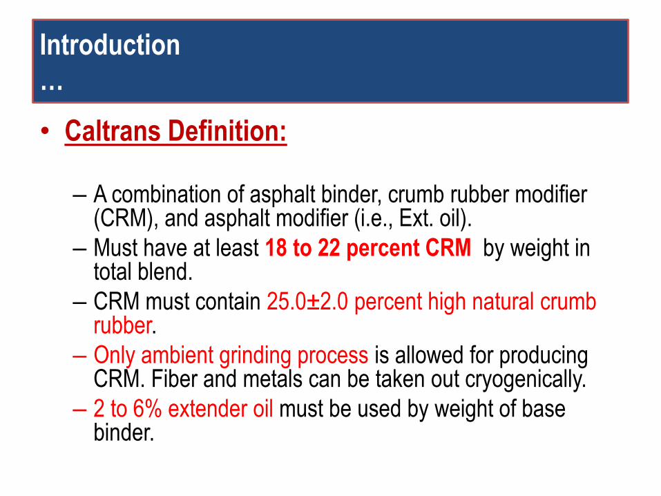
• Caltrans Definition:
– A combination of asphalt binder, crumb rubber modifier (CRM), and asphalt modifier (i.e., Ext. oil).
– Must have at least 18 to 22 percent CRM by weight in total blend.
– CRM must contain 25.0±2.0 percent high natural crumb rubber.
– Only ambient grinding process is allowed for producing CRM. Fiber and metals can be taken out cryogenically.
– 2 to 6% extender oil must be used by weight of base binder.
Introduction
Production of Asphalt Rubber Binder in California
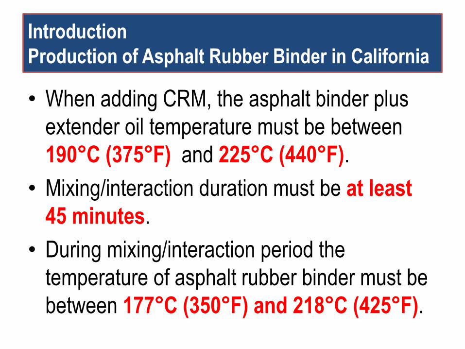
• When adding CRM, the asphalt binder plus
extender oil temperature must be between
190°C (375°F) and 225°C (440°F).
• Mixing/interaction duration must be at least
45 minutes.
• During mixing/interaction period the
temperature of asphalt rubber binder must be
between 177°C (350°F) and 218°C (425°F).
Introduction
Mixing Temp. for Asphalt Rubber Binder
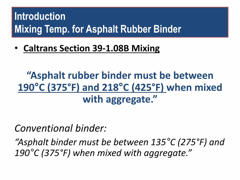
• Caltrans Section 39-1.08B Mixing
“Asphalt rubber binder must be between 190°C (375°F) and 218°C (425°F) when mixed
with aggregate.”
Conventional binder: “Asphalt binder must be between 135°C (275°F) and 190°C (375°F) when mixed with aggregate.”
Problem statement
Limitations of the Current RTFO Test Method
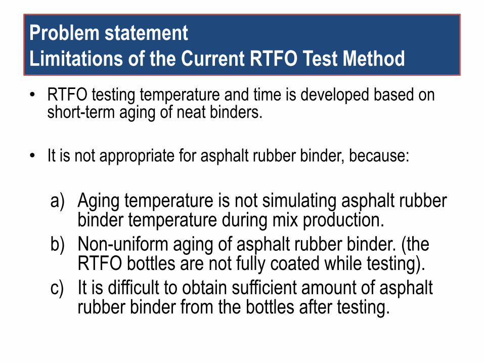
• RTFO testing temperature and time is developed based on short-term aging of neat binders.
• It is not appropriate for asphalt rubber binder, because:
a) Aging temperature is not simulating asphalt rubber binder temperature during mix production.
b) Non-uniform aging of asphalt rubber binder. (the RTFO bottles are not fully coated while testing).
c) It is difficult to obtain sufficient amount of asphalt rubber binder from the bottles after testing.
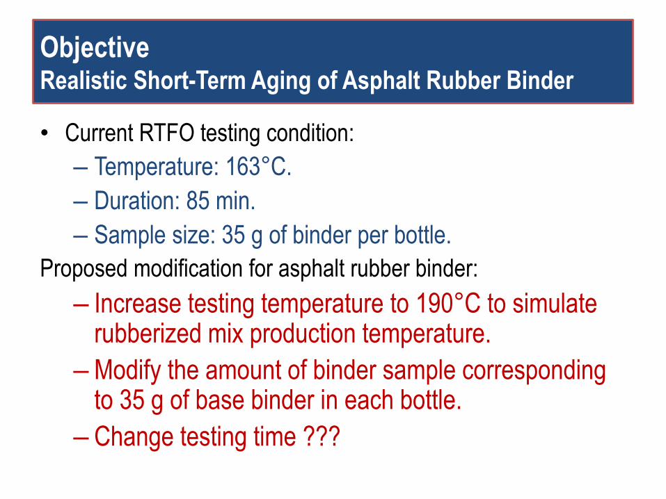
Objective Realistic Short-Term Aging of Asphalt Rubber Binder
• Current RTFO testing condition:
– Temperature: 163°C.
– Duration: 85 min.
– Sample size: 35 g of binder per bottle.
Proposed modification for asphalt rubber binder:
– Increase testing temperature to 190°C to simulate rubberized mix production temperature.
– Modify the amount of binder sample corresponding to 35 g of base binder in each bottle.
– Change testing time ???
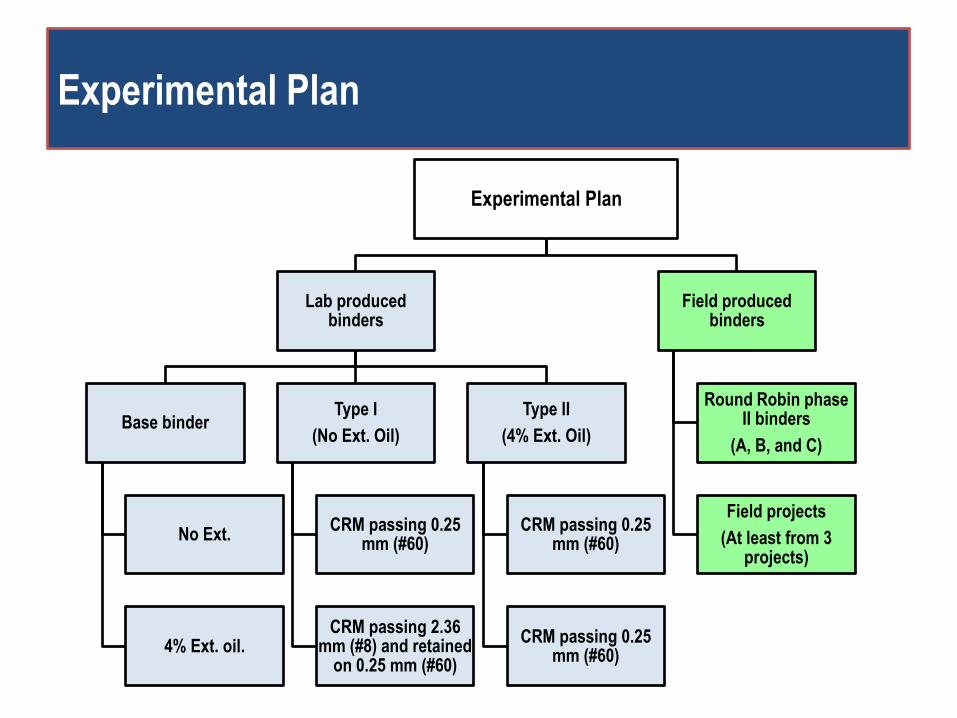
Experimental Plan
Experimental Plan
Lab produced binders
Base binder
No Ext.
4% Ext. oil.
Type I
(No Ext. Oil)
CRM passing 0.25 mm (#60)
CRM passing 2.36 mm (#8) and retained
on 0.25 mm (#60)
Type II
(4% Ext. Oil)
CRM passing 0.25 mm (#60)
CRM passing 0.25 mm (#60)
Field produced binders
Round Robin phase II binders
(A, B, and C)
Field projects
(At least from 3 projects)
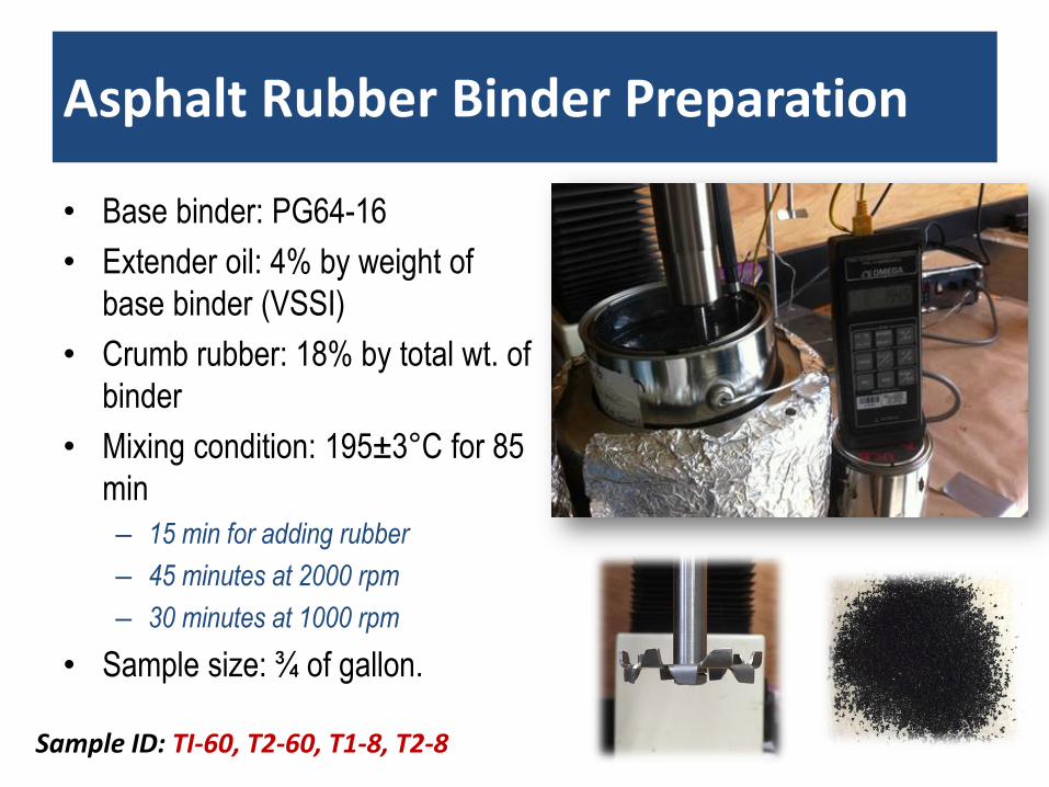
Asphalt Rubber Binder Preparation
• Base binder: PG64-16
• Extender oil: 4% by weight of
base binder (VSSI)
• Crumb rubber: 18% by total wt. of
binder
• Mixing condition: 195±3°C for 85
min
– 15 min for adding rubber
– 45 minutes at 2000 rpm
– 30 minutes at 1000 rpm
• Sample size: ¾ of gallon.
Sample ID: TI-60, T2-60, T1-8, T2-8
Test Methods
Rheology:
High temperature performance-related properties
Concentric Cylinder Geometry
Chemistry:
Degree of oxidation ( FTIR measurements)
Degree of volatilization
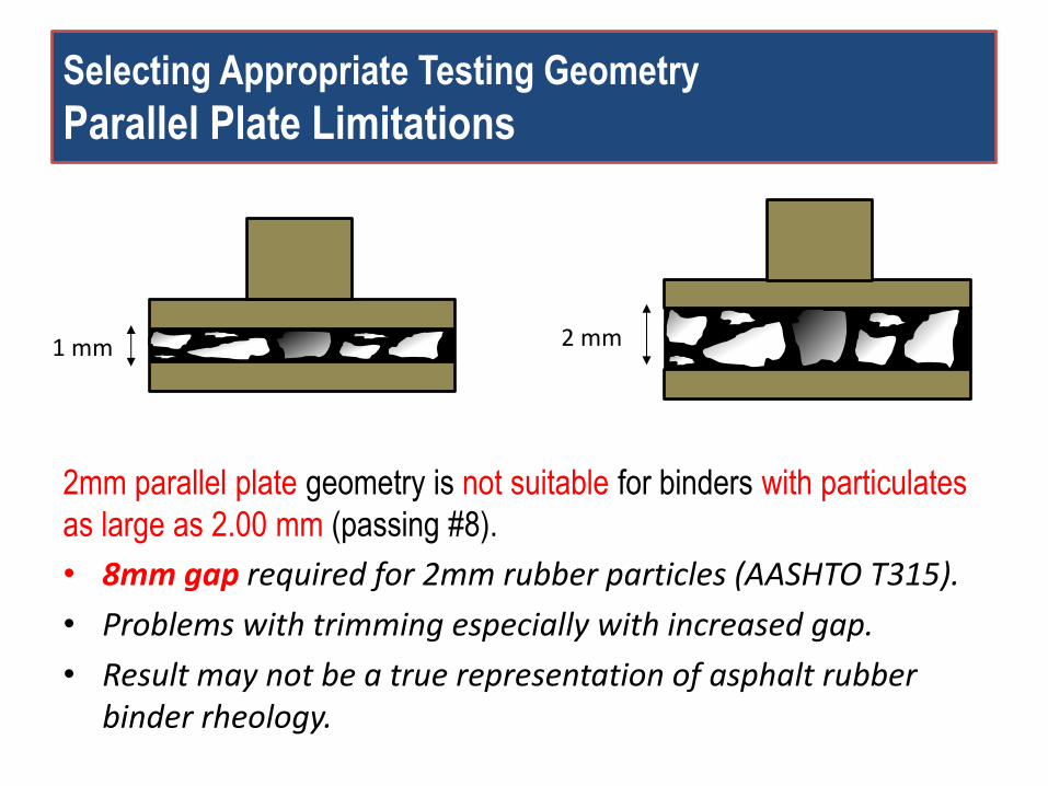
Selecting Appropriate Testing Geometry
Parallel Plate Limitations
2mm parallel plate geometry is not suitable for binders with particulates
as large as 2.00 mm (passing #8).
• 8mm gap required for 2mm rubber particles (AASHTO T315).
• Problems with trimming especially with increased gap.
• Result may not be a true representation of asphalt rubber binder rheology.
1 mm 2 mm
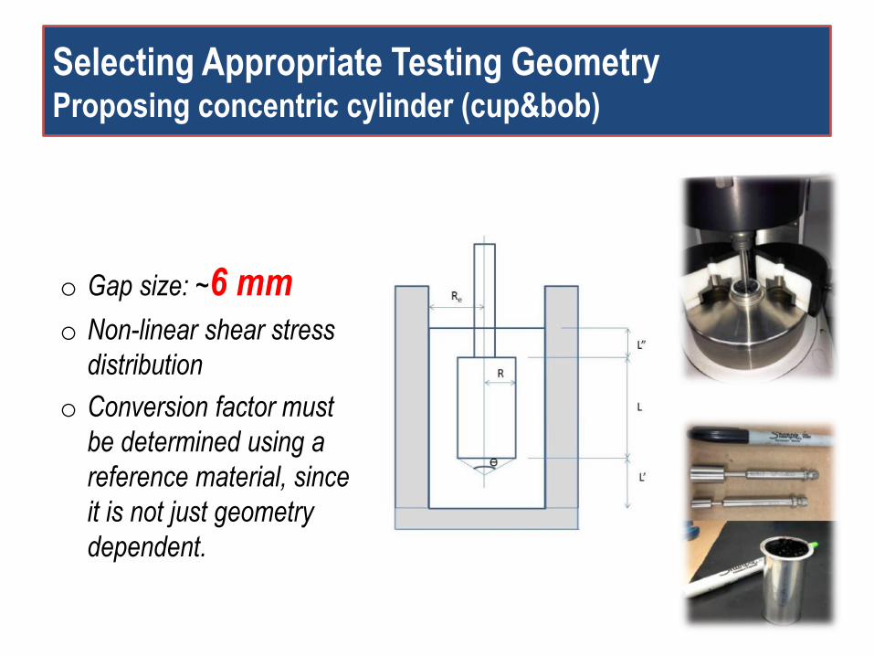
Selecting Appropriate Testing Geometry Proposing concentric cylinder (cup&bob)
o Gap size: ~6 mm o Non-linear shear stress
distribution
o Conversion factor must
be determined using a
reference material, since
it is not just geometry
dependent.
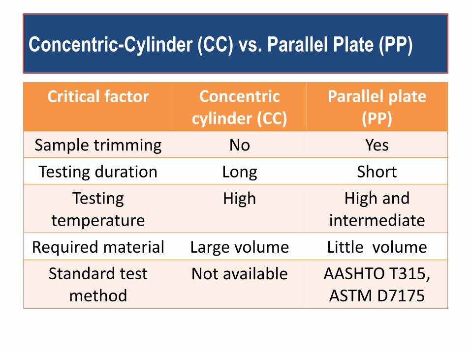
Concentric-Cylinder (CC) vs. Parallel Plate (PP)
Critical factor Concentric cylinder (CC)
Parallel plate (PP)
Sample trimming No Yes
Testing duration Long Short
Testing temperature
High High and intermediate
Required material Large volume Little volume
Standard test method
Not available AASHTO T315, ASTM D7175
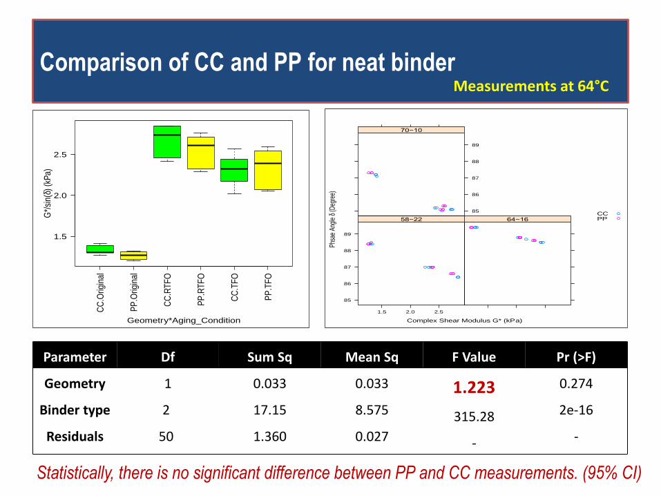
Comparison of CC and PP for neat binder
Statistically, there is no significant difference between PP and CC measurements. (95% CI)
Measurements at 64°C C
C.O
rigin
al
PP
.Orig
inal
CC
.RT
FO
PP
.RT
FO
CC
.TF
O
PP
.TF
O
1.5
2.0
2.5
G*/
sin(
d) (
kPa)
Geometry*Aging_Condition Complex Shear Modulus G* (kPa)
Phsa
e An
gle
d (D
egre
e)
85
86
87
88
89
1.5 2.0 2.5
58−22 64−16
85
86
87
88
89
70−10
CCPP
Parameter Df Sum Sq Mean Sq F Value Pr (>F)
Geometry
Binder type
Residuals
1
2
50
0.033
17.15
1.360
0.033
8.575
0.027
1.223
315.28
-
0.274
2e-16
-

Results and Discussion
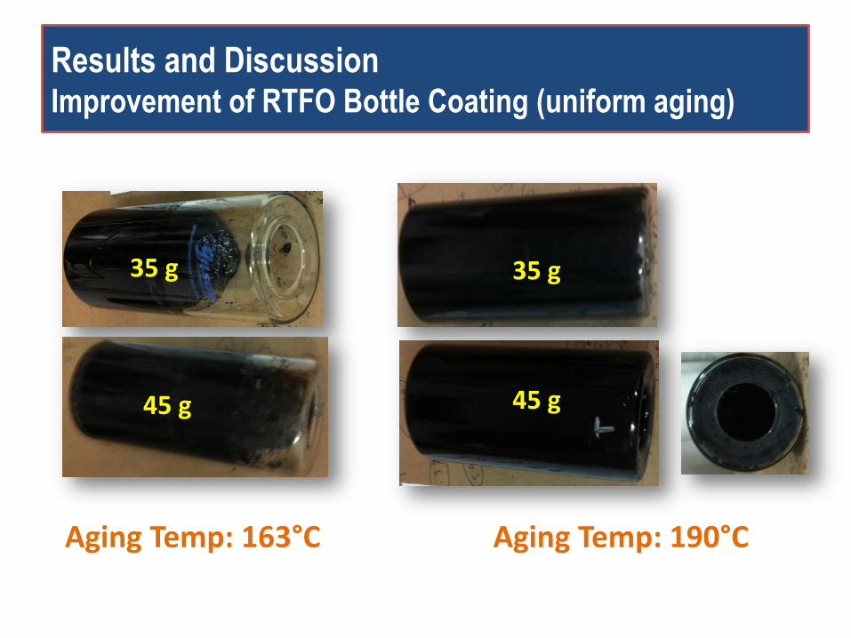
Results and Discussion Improvement of RTFO Bottle Coating (uniform aging)
35 g
45 g
Aging Temp: 163°C Aging Temp: 190°C
35 g
45 g
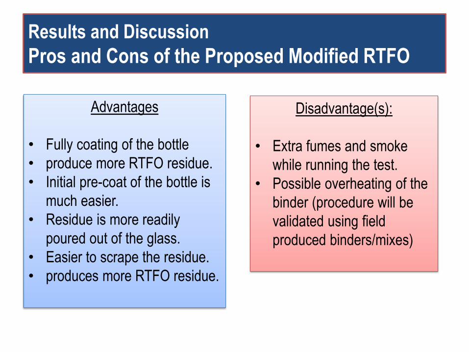
Results and Discussion
Pros and Cons of the Proposed Modified RTFO
Advantages
• Fully coating of the bottle
• produce more RTFO residue.
• Initial pre-coat of the bottle is
much easier.
• Residue is more readily
poured out of the glass.
• Easier to scrape the residue.
• produces more RTFO residue.
Disadvantage(s):
• Extra fumes and smoke
while running the test.
• Possible overheating of the
binder (procedure will be
validated using field
produced binders/mixes)
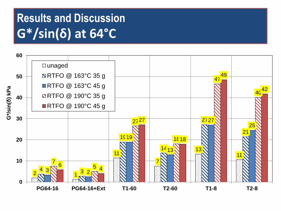
Results and Discussion
G*/sin(δ) at 64°C
2 1
11
7
13 11
4 3
19
14
27
21
3 2
19
13
27 25
7 5
27
18
47
40
6 4
27
18
49
42
0
10
20
30
40
50
60
PG64-16 PG64-16+Ext T1-60 T2-60 T1-8 T2-8
G*/
sin
(δ)
kP
a
unaged
RTFO @ 163°C 35 g
RTFO @ 163°C 45 g
RTFO @ 190°C 35 g
RTFO @ 190°C 45 g
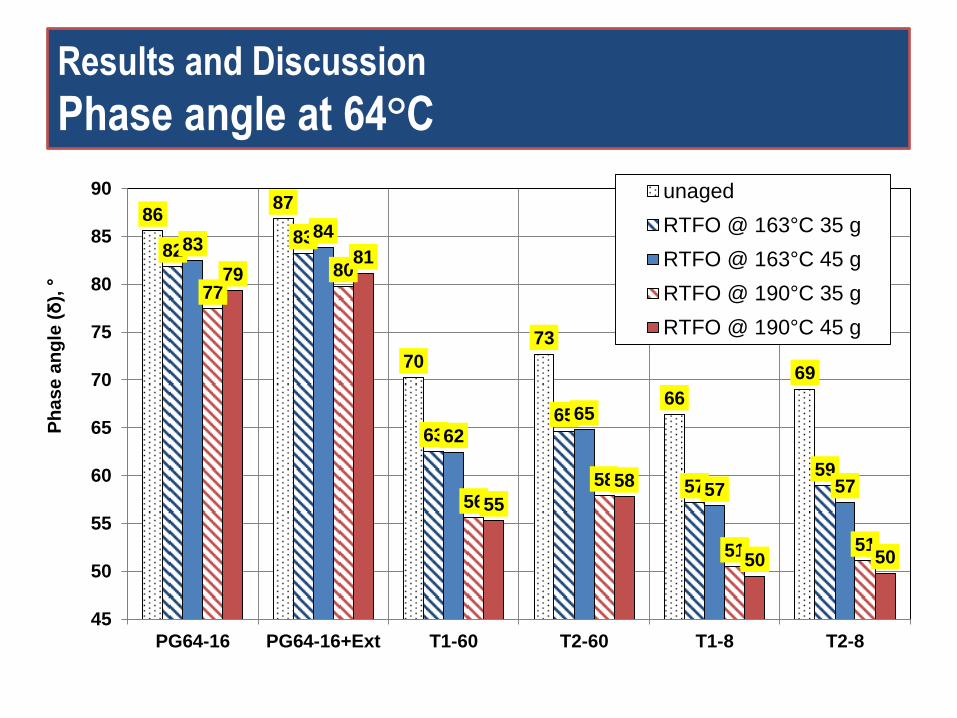
Results and Discussion
Phase angle at 64°C
86 87
70
73
66
69
82 83
63 65
57 59
83 84
62
65
57 57
77
80
56
58
51 51
79 81
55
58
50 50
45
50
55
60
65
70
75
80
85
90
PG64-16 PG64-16+Ext T1-60 T2-60 T1-8 T2-8
Ph
as
e a
ng
le (δ
), °
unaged
RTFO @ 163°C 35 g
RTFO @ 163°C 45 g
RTFO @ 190°C 35 g
RTFO @ 190°C 45 g
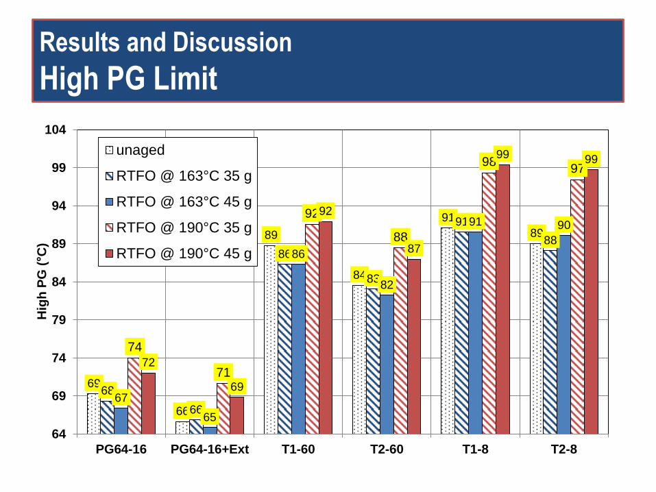
Results and Discussion
High PG Limit
69
66
89
84
91
89
68
66
86
83
91
88
67
65
86
82
91 90
74
71
92
88
98 97
72
69
92
87
99 99
64
69
74
79
84
89
94
99
104
PG64-16 PG64-16+Ext T1-60 T2-60 T1-8 T2-8
Hig
h P
G (°C
)
unaged
RTFO @ 163°C 35 g
RTFO @ 163°C 45 g
RTFO @ 190°C 35 g
RTFO @ 190°C 45 g
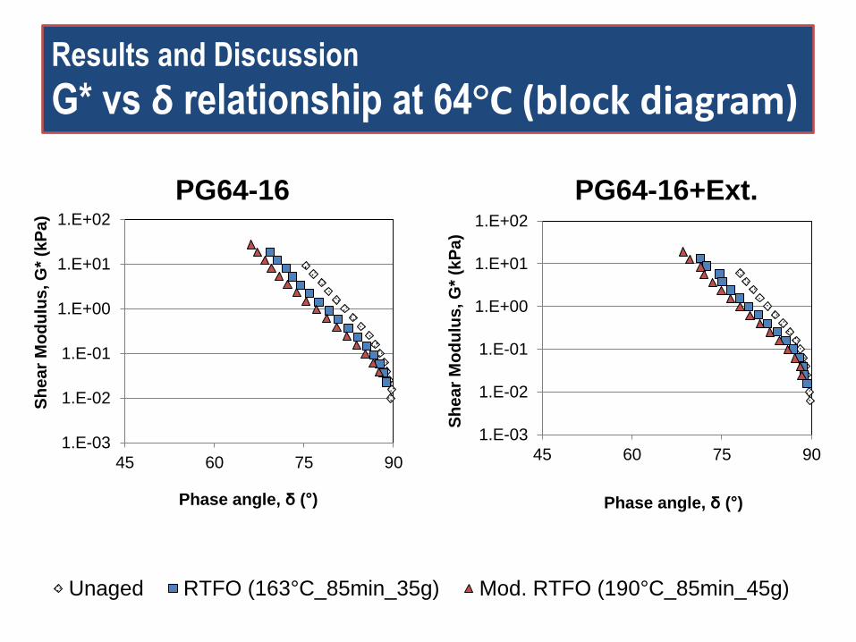
Results and Discussion
G* vs δ relationship at 64°C (block diagram)
1.E-03
1.E-02
1.E-01
1.E+00
1.E+01
1.E+02
45 60 75 90
Sh
ea
r M
od
ulu
s, G
* (k
Pa
)
Phase angle, δ (°)
PG64-16
1.E-03
1.E-02
1.E-01
1.E+00
1.E+01
1.E+02
45 60 75 90S
he
ar
Mo
du
lus
, G
* (k
Pa
)
Phase angle, δ (°)
PG64-16+Ext.
1.E-03
1.E+02
45 55 65 75 85Sh
ea
r M
od
ulu
s,
G*
(kP
a)
Phase angle, δ (°)
PG64-16 Unaged RTFO (163°C_85min_35g) Mod. RTFO (190°C_85min_45g)
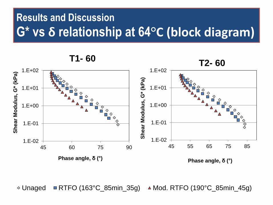
Results and Discussion
G* vs δ relationship at 64°C (block diagram)
1.E-02
1.E-01
1.E+00
1.E+01
1.E+02
45 60 75 90
Sh
ea
r M
od
ulu
s, G
* (k
Pa
)
Phase angle, δ (°)
T1- 60
1.E-02
1.E-01
1.E+00
1.E+01
1.E+02
45 55 65 75 85S
he
ar
Mo
du
lus
, G
* (k
Pa
)
Phase angle, δ (°)
T2- 60
1.E-03
1.E+02
45 55 65 75 85Sh
ea
r M
od
ulu
s,
G*
(kP
a)
Phase angle, δ (°)
PG64-16 Unaged RTFO (163°C_85min_35g) Mod. RTFO (190°C_85min_45g)
1.E-01
1.E+00
1.E+01
1.E+02
1.E+03
45 60 75 90
Sh
ea
r M
od
ulu
s, G
* (k
Pa
)
Phase angle, δ (°)
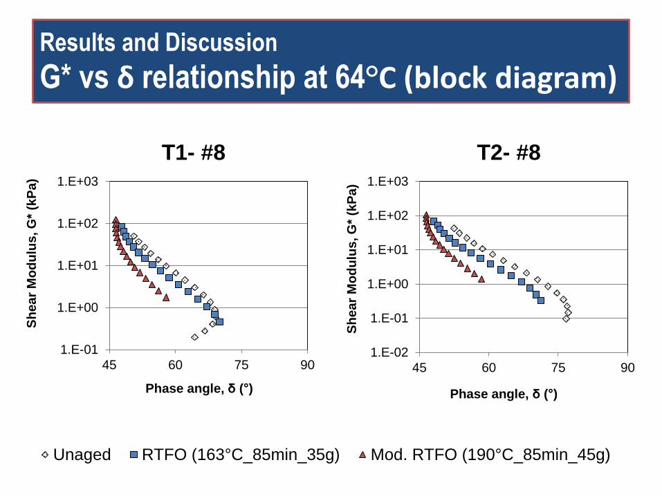
T1- #8
1.E-02
1.E-01
1.E+00
1.E+01
1.E+02
1.E+03
45 60 75 90
Sh
ea
r M
od
ulu
s, G
* (k
Pa
)
Phase angle, δ (°)
T2- #8
Results and Discussion
G* vs δ relationship at 64°C (block diagram)
1.E-03
1.E+02
45 55 65 75 85Sh
ea
r M
od
ulu
s,
G*
(kP
a)
Phase angle, δ (°)
PG64-16 Unaged RTFO (163°C_85min_35g) Mod. RTFO (190°C_85min_45g)
Summary of Findings
• As expected, increasing short-term aging
temperature resulted in:
– Increasing binder stiffness
– reducing phase angle.
• Larger sample size result reduced the aging effect.
However, it is not as effective as aging temperature.
• Increasing the aging temperature to 190°C
increased the high PG temperature by up to 9°C.
Work in Progress…
• Analyzing change in chemistry of asphalt binder
– Quantifying degree of oxidation (Carbonyl and Sulfoxide functional groups)
– Quantifying degree of volatilization
• Comparing RTFO and TFO test results
• Testing field blended asphalt rubber binders
• Comparing properties of binder in rubberized mix and modified and conventional RTFO aged binders
• Evaluating RTFO test duration, if needed.