Embed Size (px)
Citation preview
RTFO TouchRolling Thin Film Oven
INSTRUCTION MANUAL
This manual contains important operating and safety information. Carefully read and understand the contents of this manual prior to the operation of this equipment.
www.atspa.com

REVISED SEPTEMBER 2017
Information in this document is subject to change without notice and does not represent a commitment on the part of Applied Test Systems (ATS).
© Copyright Applied Test Systems 2017
For assistance with set-up or operation, contact the ATS service department. Please have this manual and product serial number available when you call.
Telephone: +1-724-283-1212.
Rolling Thin Film Oven (RTFO Touch) | Table of Contents i
MANUAL CONTENTS
A. Introduction .................................................................................................................... 1A.1 Unpacking ................................................................................................................................................... 1
A.2 After Sale Support ....................................................................................................................................... 1
B. Safety .............................................................................................................................. 2B.1 For Owners, Operators, and Maintenance .................................................................................................. 2B.2 Warnings ..................................................................................................................................................... 2
B.3 Cautions ...................................................................................................................................................... 3
C. System Overview ........................................................................................................... 5C.1 Equipment Parts ......................................................................................................................................... 5
Front of Unit .......................................................................................................................................... 5Back of Unit ........................................................................................................................................... 6Interior Chamber ................................................................................................................................... 7Interior Controls .................................................................................................................................... 8
C.2 General Description .................................................................................................................................... 9Accessory Items .................................................................................................................................... 9
Product Specifications .......................................................................................................................... 9
D. Installation .................................................................................................................... 10D.1 General Installation ....................................................................................................................................10D.2 Leveling the Machine ................................................................................................................................ 10
D.3 Remote Communication Setup (Optional) ................................................................................................ 11
E. Verification .................................................................................................................... 12E.1 Temperature Verification ....................................................................................................................12E.2 Verification of Air Flow ....................................................................................................................... 12
F. Operation ............................................................................................................. 13F.1 Test Setup ...................................................................................................................................................13
Language .............................................................................................................................................14
Preheat ................................................................................................................................................14Cycle Time (min) ..................................................................................................................................15Cycle Temperature (°C) .......................................................................................................................15Cycle Air Flow (mL/min) .......................................................................................................................15Current Time ........................................................................................................................................15Preheat Delay (Optional) .....................................................................................................................15
F.2 Run Test .................................................................................................................................................... 16
G. Troubleshooting ........................................................................................................... 18G.1 Preface ......................................................................................................................................................18G.2 Unit Will Not Turn On ................................................................................................................................ 18G.3 Unit Will Not Heat ..................................................................................................................................... 19G.4 Carousel Will Not Rotate .......................................................................................................................... 19G.5 Fan Motor Will Not Rotate ........................................................................................................................ 20
G.6 Unit Has No Airflow ....................................................................................................................................20
H. Maintenance ................................................................................................................. 21H.1 Cleaning the Unit .......................................................................................................................................21H.2 Greasing the Bearings .............................................................................................................................. 21
Rear Bearing ........................................................................................................................................21Front Inside Bearing .............................................................................................................................21
H.3 Chain Maintenance ................................................................................................................................... 22H.4 Tray Cleaning ............................................................................................................................................ 23H.5 Replacement Parts ................................................................................................................................... 24
APPENDIX A: Warranty ..................................................................................................... 25
APPENDIX B: Wiring Diagram .......................................................................................... 26
APPENDIX C: Image Glossary.......................................................................................... 28
Rolling Thin Film Oven (RTFO Touch) | Table of Contentsii
Rolling Thin Film Oven (RTFO Touch) | A. Introduction 1
A. Introduction
A.1 Unpacking
Retain all cartons and packing materials until the unit is operated and found to be in good condition. If damage has occurred during shipping, notify Applied Test Systems (ATS) and the carrier immediately. If it is necessary to file a damage claim, retain the packing materials for inspection by the carrier.
A.2 After Sale Support
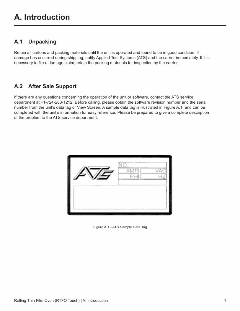
If there are any questions concerning the operation of the unit or software, contact the ATS service department at +1-724-283-1212. Before calling, please obtain the software revision number and the serial number from the unit’s data tag or View Screen. A sample data tag is illustrated in Figure A.1, and can be completed with the unit’s information for easy reference. Please be prepared to give a complete description of the problem to the ATS service department.
Figure A.1 - ATS Sample Data Tag
Rolling Thin Film Oven (RTFO Touch) | B. Safety2
B. Safety
B.1 For Owners, Operators, and Maintenance
Read and understand all instructions and safety precautions listed in this manual before installing or operating the unit. If there are any questions regarding operation of the unit or the instructions in this manual, contact the ATS service department at +1-724-283-1212.
In addition to the safety warnings listed on the equipment, warnings are posted throughout this manual. Read and follow these important instructions. Failure to observe these instructions can result in permanent damage to the unit, significant property damage, personal injury, or death.
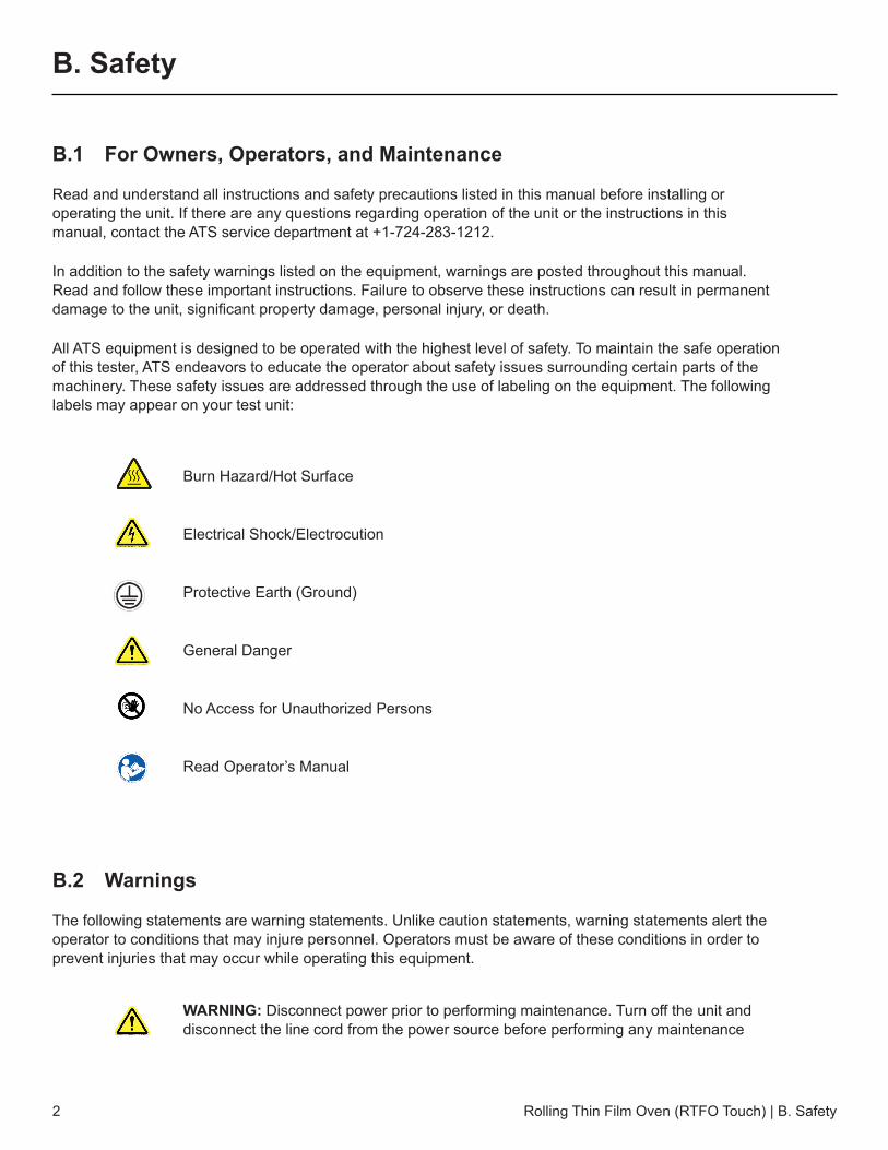
All ATS equipment is designed to be operated with the highest level of safety. To maintain the safe operation of this tester, ATS endeavors to educate the operator about safety issues surrounding certain parts of the machinery. These safety issues are addressed through the use of labeling on the equipment. The following labels may appear on your test unit:
Burn Hazard/Hot Surface
Electrical Shock/Electrocution
Protective Earth (Ground)
General Danger
No Access for Unauthorized Persons
Read Operator’s Manual
B.2 Warnings
The following statements are warning statements. Unlike caution statements, warning statements alert the operator to conditions that may injure personnel. Operators must be aware of these conditions in order to prevent injuries that may occur while operating this equipment.
WARNING: Disconnect power prior to performing maintenance. Turn off the unit and disconnect the line cord from the power source before performing any maintenance
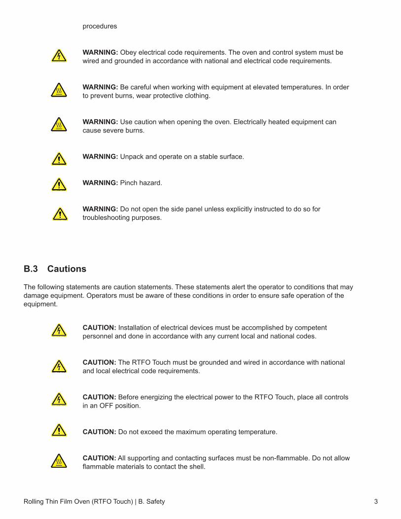
procedures
WARNING: Obey electrical code requirements. The oven and control system must be wired and grounded in accordance with national and electrical code requirements.
WARNING: Be careful when working with equipment at elevated temperatures. In order to prevent burns, wear protective clothing.
WARNING: Use caution when opening the oven. Electrically heated equipment can cause severe burns.
WARNING: Unpack and operate on a stable surface.
WARNING: Pinch hazard.
WARNING: Do not open the side panel unless explicitly instructed to do so for troubleshooting purposes.
B.3 Cautions
The following statements are caution statements. These statements alert the operator to conditions that may damage equipment. Operators must be aware of these conditions in order to ensure safe operation of the equipment.
CAUTION: Installation of electrical devices must be accomplished by competent personnel and done in accordance with any current local and national codes.
CAUTION: The RTFO Touch must be grounded and wired in accordance with national and local electrical code requirements.
CAUTION: Before energizing the electrical power to the RTFO Touch, place all controls in an OFF position.
CAUTION: Do not exceed the maximum operating temperature.
CAUTION: All supporting and contacting surfaces must be non-flammable. Do not allow flammable materials to contact the shell.
Rolling Thin Film Oven (RTFO Touch) | B. Safety 3

CAUTION: If an emergency shutdown needs to be performed, place ON/OFF switch in an OFF position.
CAUTION: Do not overflow RTFO Touch bottles. Refer to test specifications for proper amount of material.
Rolling Thin Film Oven (RTFO Touch) | B. Safety4
Rolling Thin Film Oven (RTFO Touch) | C. System Overview 5
C. System Overview
C.1 Equipment Parts
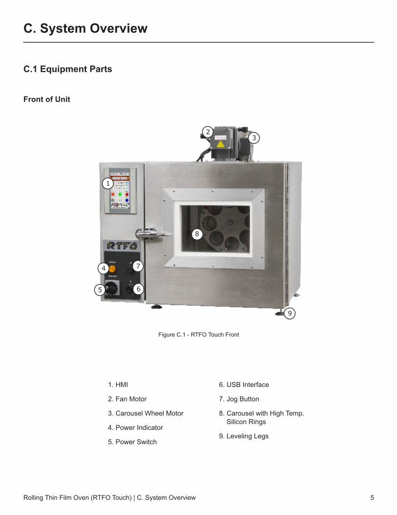
Front of Unit
1. HMI
2. Fan Motor
3. Carousel Wheel Motor
4. Power Indicator
5. Power Switch
6. USB Interface
7. Jog Button
8. Carousel with High Temp.Silicon Rings
9. Leveling Legs
Figure C.1 - RTFO Touch Front
1
23
4
5 6
7
9
8
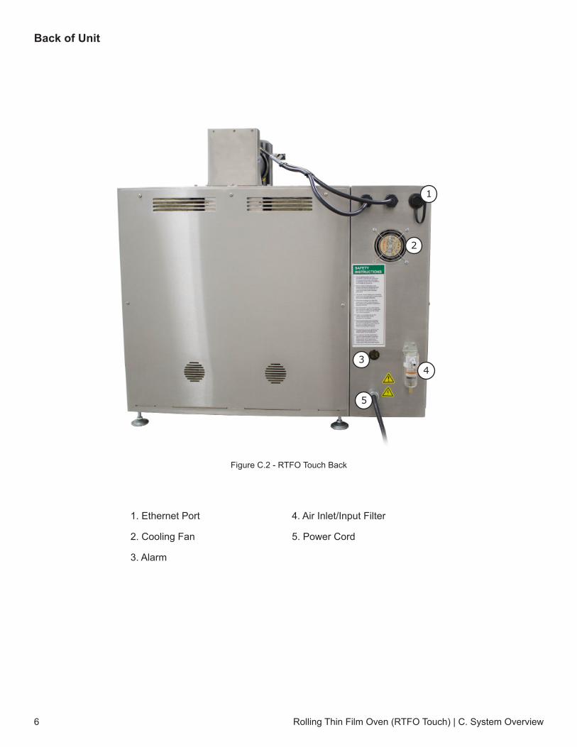
Back of Unit
Rolling Thin Film Oven (RTFO Touch) | C. System Overview6
1. Ethernet Port
2. Cooling Fan
3. Alarm
4. Air Inlet/Input Filter
5. Power Cord
Figure C.2 - RTFO Touch Back
1
2
43
5
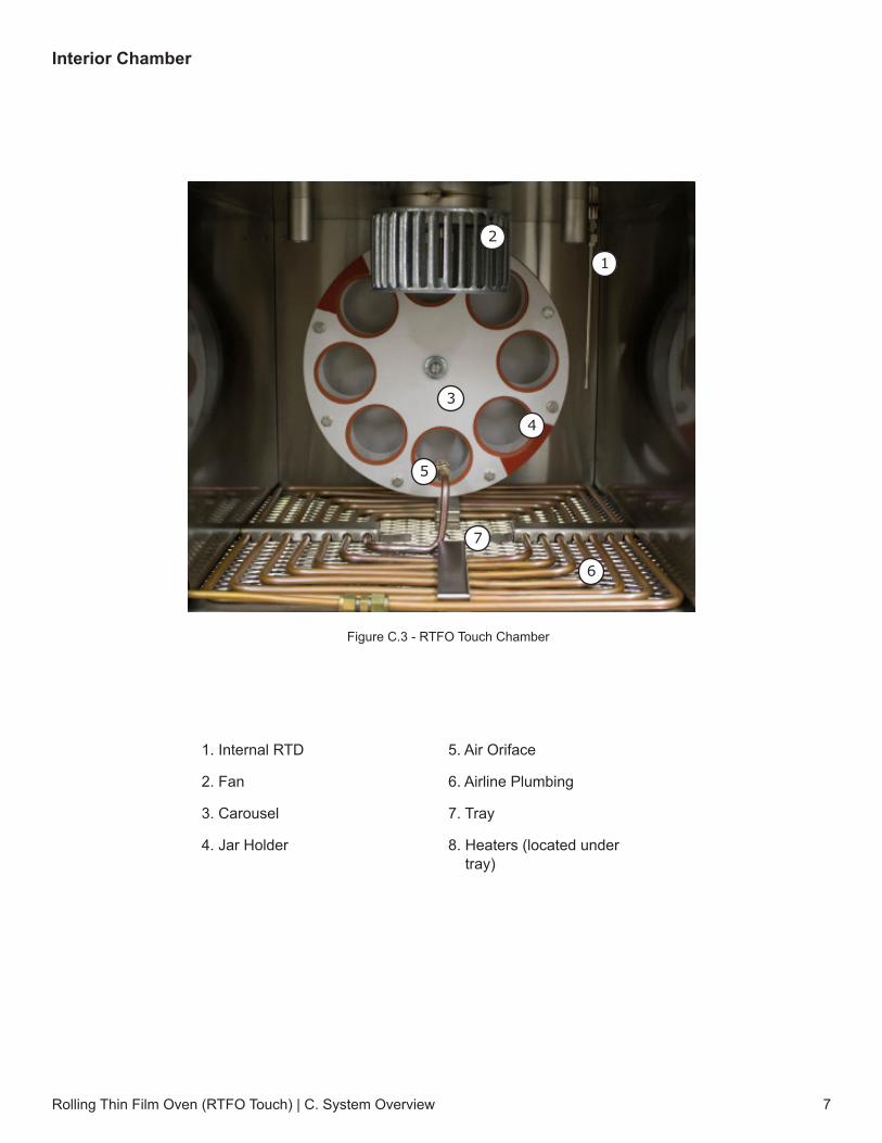
Interior Chamber
Rolling Thin Film Oven (RTFO Touch) | C. System Overview 7
1. Internal RTD
2. Fan
3. Carousel
4. Jar Holder
5. Air Oriface
6. Airline Plumbing
7. Tray
8. Heaters (located undertray)
Figure C.3 - RTFO Touch Chamber
1
2
3
4
5
6
7
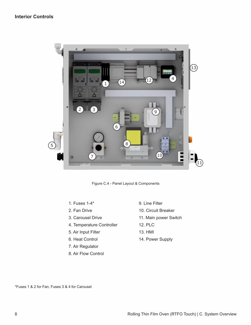
Interior Controls
*Fuses 1 & 2 for Fan, Fuses 3 & 4 for Carousel
Rolling Thin Film Oven (RTFO Touch) | C. System Overview8
1. Fuses 1-4*2. Fan Drive3. Carousel Drive4. Temperature Controller5. Air Input Filter6. Heat Control7. Air Regulator8. Air Flow Control
9. Line Filter10. Circuit Breaker11. Main power Switch12. PLC13. HMI14. Power Supply
Figure C.4 - Panel Layout & Components
1 14 12 4
13
32
5
7
6
8
9
10
11
Rolling Thin Film Oven (RTFO Touch) | C. System Overview 9
C.2 General Description
The RTFO Touch provides a controlled flow of heated air directed into the openings of horizontal glass bottles as they rotate on a carousel rack, simulating short term aging of binder during production, handling, and paving operations. It exceeds ASTM D2872, AASHTO T 240 and California 346 testing standards with a 5 to 8 minute recovery time.
When operating the RTFO Touch, always make sure to wear the proper personal protective gear (PPG), including high temperature work gloves.
Accessory Items
• Specimen Containers• RTFO Bottle Scraper• Specimen Removal Tool/Tongs
Product Specifications
Size 32.5 in. W x 28.25 in. D x 32 in. H
Power Requirements
230 V 1-Phase, 50/60 Hz, 20 amps
Air Pressure 60 PSI inlet pressure (414 kpa) @ Class 3 Quality max particle of 5um

Rolling Thin Film Oven (RTFO Touch) | D. Installation10
D. Installation
D.1 General Installation
The following procedure describes how to properly unpack, connect, and power the RTFO Touch.
1. Carefully remove the RTFO Touch from shipping packaging, removing any packing material and/oraccessories that may have been placed inside of the oven chamber for shipment.
2. Connect the power cord to the proper receptacle on the wall. Be sure to verify that the power switch onthe front is in the OFF position.
3. This unit is a 230-240 VAC 50/60 Hz/20 amp capacity, and requires an air supply of at least 90 PSI.
4. Rotate the power switch on the front from the horizontal OFF position to the vertical ON position (FigureD.1 and Figure D.2) to turn the unit on. The power light above the switch should now be illuminated.
5. Set up the air by installing your male air fitting into the female receiver(Figure D.3). Secure with Teflon tape.
D.2 Leveling the Machine
1. Using a digital level check the level on the top of the RTFO and thebottom portion of the RTFO for a reference point
2. Insert a cut jar in the carriage to check the level at different points ofrotation. The level should be +/- 1.0 Degrees from the reference point
3. If adjustments are needed, adjust the legs on the bottom of the RTFOuntil level.
Figure D.1 - Power switch in the OFF position
Figure D.2 - Power switch in the ON position
Figure D.3 - RTFO female air connection
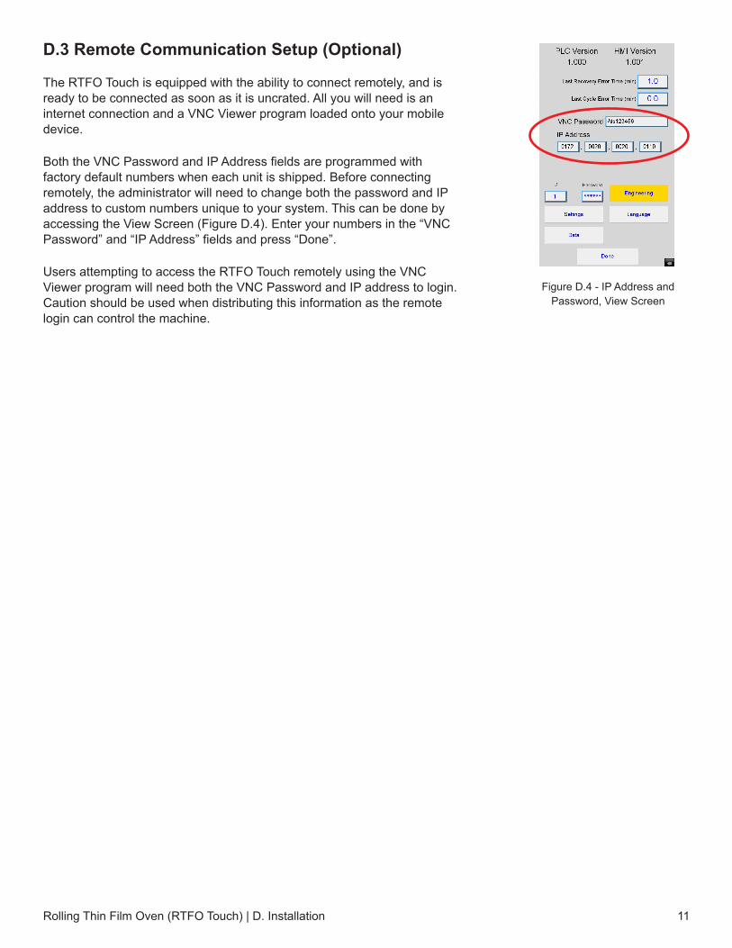
D.3 Remote Communication Setup (Optional)
The RTFO Touch is equipped with the ability to connect remotely, and is ready to be connected as soon as it is uncrated. All you will need is an internet connection and a VNC Viewer program loaded onto your mobile device.
Both the VNC Password and IP Address fields are programmed with factory default numbers when each unit is shipped. Before connecting remotely, the administrator will need to change both the password and IP address to custom numbers unique to your system. This can be done by accessing the View Screen (Figure D.4). Enter your numbers in the “VNC Password” and “IP Address” fields and press “Done”.
Users attempting to access the RTFO Touch remotely using the VNC Viewer program will need both the VNC Password and IP address to login. Caution should be used when distributing this information as the remote login can control the machine.
Rolling Thin Film Oven (RTFO Touch) | D. Installation 11
Figure D.4 - IP Address and Password, View Screen
Rolling Thin Film Oven (RTFO Touch) | E. Verification12
E. Verification
E.1 Temperature Verification
1. Insert a temperature probe into the top left porthole
2. Connect probe with a brass block to the RTD inside (right side)
3. On the HMI select “Preheat”
4. Allow unit to heat up and stabilize
5. Once stabilized at the temperature that needs verifying, take 5 readings, 10 minutes apart and compare results.
E.2 Verification of Air Flow
1. Attach a flow verification device to the copper tubing inside the RTFO (if using a flow through device the orificecan be removed from the tubing and attached to the downstream end.
2. Allow 15 minutes to stabilize
3. Take 5 comparison readings every 3-5 minutes. 3 readings minimum, 5 recommended.
Rolling Thin Film Oven (RTFO Touch) | F. Operation 13
F. Operation
F.1 Test Setup
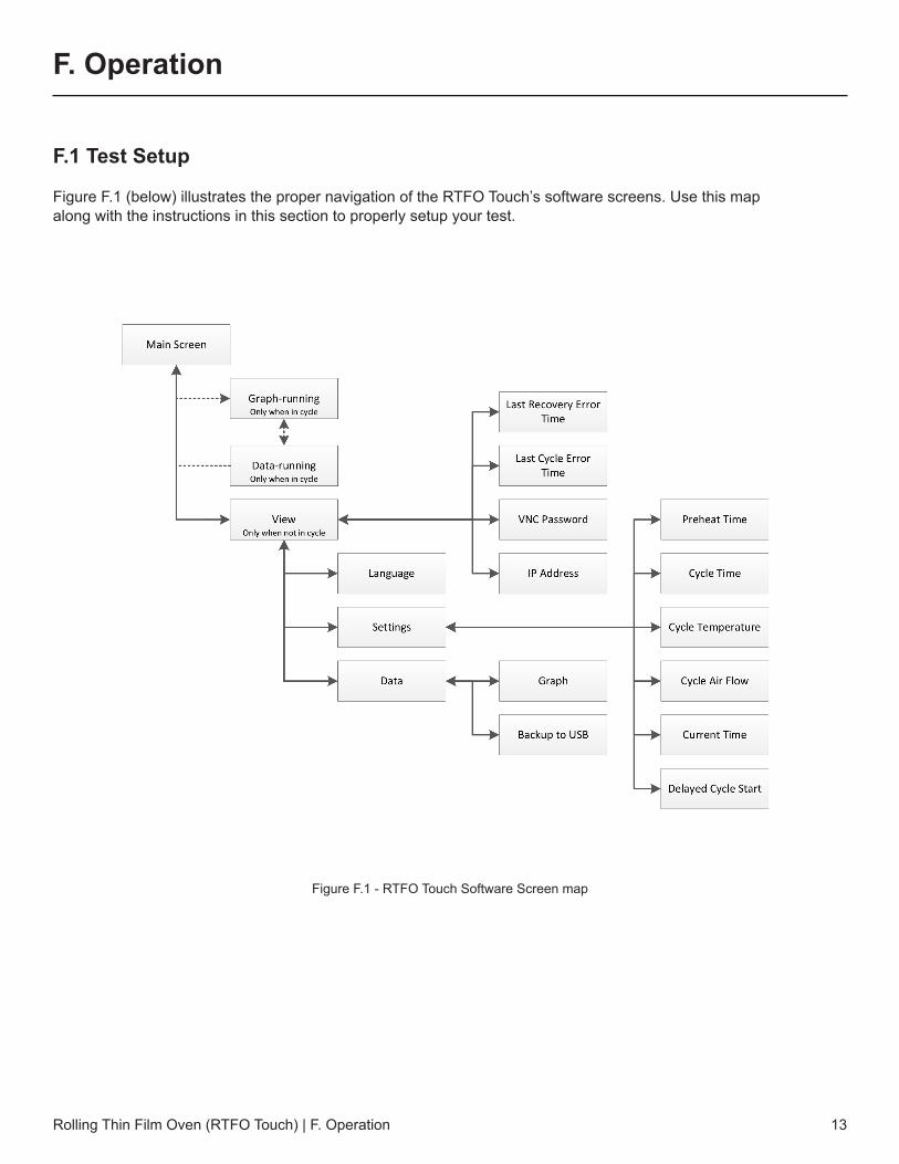
Figure F.1 (below) illustrates the proper navigation of the RTFO Touch’s software screens. Use this map along with the instructions in this section to properly setup your test.
Figure F.1 - RTFO Touch Software Screen map

Once the RTFO Touch has been turned on, the Main Screen (Figure F.2) will launch. This screen screen will show values for machine temperature and air flow. It also has several controls to set-up and run the machine.
Language
1. From the Main Screen (Figure F.2) press the “View” button to access the View Screen (Figure F.3).
2. Once on the View Screen, press the “Language” button located at the bottom of the screen.
3. This will take you to the Language Screen (Figure F.4), which will presentyou with several language choices. Select the appropriate language foroperation, then press “Done” to return to the View Screen.
Preheat
1. From the View Screen, press the “Settings” button to access the SettingsScreen (Figure F.5). The majority of your test setup will occur on this screen.
2. On the Settings Screen, the Preheat (min) field indicates the amount oftime the system heats after the “Preheat” button is pressed. The systemstatus bar on the Main Screen will read “Preheat” during this time. Using thetouchscreen, enter your desired preheat time into this section.
Figure F.5 - Settings Screen
Rolling Thin Film Oven (RTFO Touch) | F. Operation14
Figure F.2 - Main Screen Figure F.3 - View Screen Figure F.4 - Language Screen
Cycle Time (min)
1. Below the Preheat field there is a field for the Cycle Time (min). The Cycle Time (min) field indicates theamount of time the system runs the cycle after the “Run Cycle” button is pressed. Enter your desired cycle/aging time here.
Cycle Temperature (°C)
1. Below the Cycle Time (min) field is the Cycle Temperature (°C) field. Use this field to enter thetemperature set point you require the system to reach during preheat.
Cycle Air Flow (mL/min)
1. Below the Cycle Temperature (°C) field is the Cycle Air Flow (mL/min) field. Enter the air flow set pointrequired when the cycle is running here.
Current Time
1. The Current Time section located below the Cycle Air Flow (mL/min) field allow the operator to set thecurrent date and time. These settings are used to log test data files. Verify that this information is correct, oradjust as needed using the touchscreen.
2. If you do not need to set a Preheat Delay for your system, press the “Done” button now to return to theView Screen. Press the “Done” button a second time to return to the Main Screen and complete your testsetup.
3. If your test requires a Preheat Delay, remain on the Settings Screen and follow the instructions below.
Preheat Delay (Optional)
The RTFO Touch features an optional Preheat Delay function, which allows operators to program the system to start the preheat cycle automatically after a specific timed delay. This feature is setup using the bottom portion of the Settings Screen.
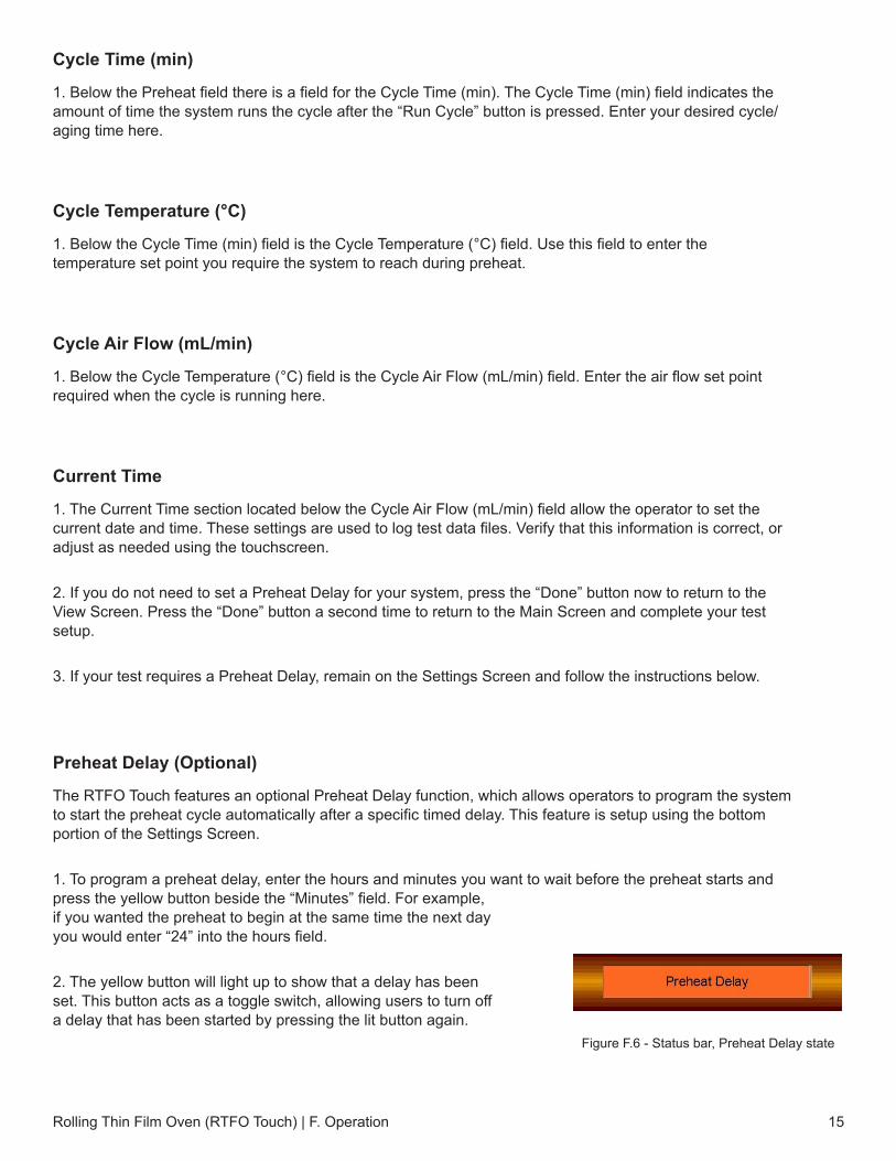
1. To program a preheat delay, enter the hours and minutes you want to wait before the preheat starts andpress the yellow button beside the “Minutes” field. For example,if you wanted the preheat to begin at the same time the next dayyou would enter “24” into the hours field.
2. The yellow button will light up to show that a delay has beenset. This button acts as a toggle switch, allowing users to turn offa delay that has been started by pressing the lit button again.
Rolling Thin Film Oven (RTFO Touch) | F. Operation 15
Figure F.6 - Status bar, Preheat Delay state
3. During an active Preheat Delay, the status bar on the Main Screen will read “Preheat Delay” (Figure F.7),and the remaining time before preheat start is shown.
4. Once you have set your Preheat Delay, press “Done” on the SETTINGS screen to return to the VIEWscreen. Press DONE on the VIEW screen to return to the MAIN screen.
F.2 Run Test
1. Press “View” on the Main Screen.
2. Once on the View Screen, press “Settings” to access the Settings Screen.
3. Verify that the Preheat Time, Cycle Time, Cycle Temperature, and Cycle Air Flow are all set up to thespecification you wish to test to.
4. Press “Done” to return to the View Screen, and then press “Done” again to return to the Main Screen.
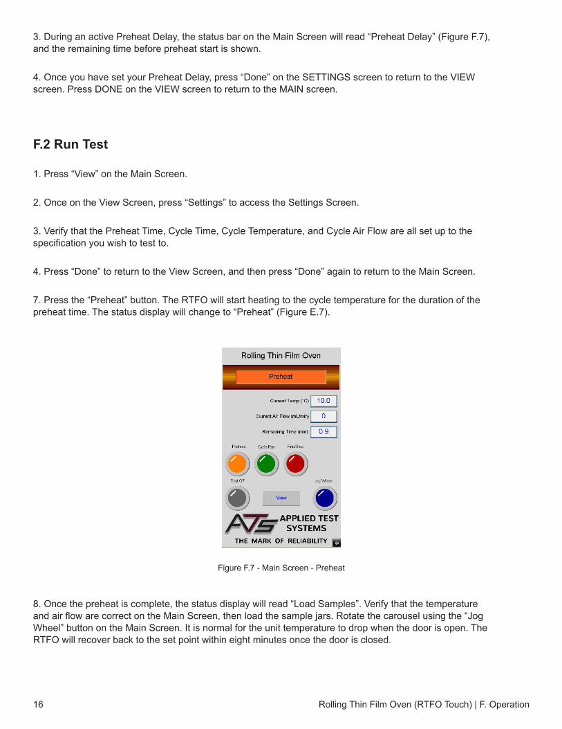
7. Press the “Preheat” button. The RTFO will start heating to the cycle temperature for the duration of thepreheat time. The status display will change to “Preheat” (Figure E.7).
8. Once the preheat is complete, the status display will read “Load Samples”. Verify that the temperatureand air flow are correct on the Main Screen, then load the sample jars. Rotate the carousel using the “JogWheel” button on the Main Screen. It is normal for the unit temperature to drop when the door is open. TheRTFO will recover back to the set point within eight minutes once the door is closed.
Rolling Thin Film Oven (RTFO Touch) | F. Operation16
Figure F.7 - Main Screen - Preheat
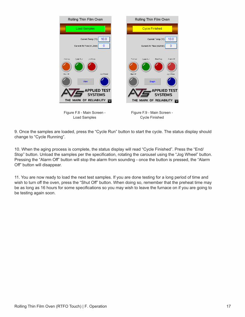
9. Once the samples are loaded, press the “Cycle Run” button to start the cycle. The status display shouldchange to “Cycle Running”.
10. When the aging process is complete, the status display will read “Cycle Finished”. Press the “End/Stop” button. Unload the samples per the specification, rotating the carousel using the “Jog Wheel” button.Pressing the “Alarm Off” button will stop the alarm from sounding - once the button is pressed, the “AlarmOff” button will disappear.
11. You are now ready to load the next test samples. If you are done testing for a long period of time andwish to turn off the oven, press the “Shut Off” button. When doing so, remember that the preheat time maybe as long as 16 hours for some specifications so you may wish to leave the furnace on if you are going tobe testing again soon.
Rolling Thin Film Oven (RTFO Touch) | F. Operation 17
Figure F.8 - Main Screen - Load Samples
Figure F.9 - Main Screen - Cycle Finished
Rolling Thin Film Oven (RTFO Touch) | G. Troubleshooting18
G. Troubleshooting
G.1 Preface
Listed within this section are the most common troubleshooting errors that operators may encounter when using the RTFO Touch. Users may follow the steps provided to work through these basic errors.
WARNING: Any additional issues or system errors should be brought to the attention of the ATS service department immediately. Please do not attempt to independently fix any other system errors. Any additional errors fixed independent of the ATS service deparment could result in damage to the equipment, or injury on the part of the operator.
WARNING: Use caution when opening the side panel when the unit is running. ONLY open the side panel when explicitly instructed to. Do not touch or alter anything within the side panel unless instructed to. Failure to adhere to this warning could result in severe electric shock, injury, or death.
G.2 Unit Will Not Turn On
1. Verify the system is plugged in to the correct power source, and that the cord is secured to the powerinput on the machine.
2. Verify the power switch on the front of the unit is in the “ON” position and the light on the front of the unit islit.
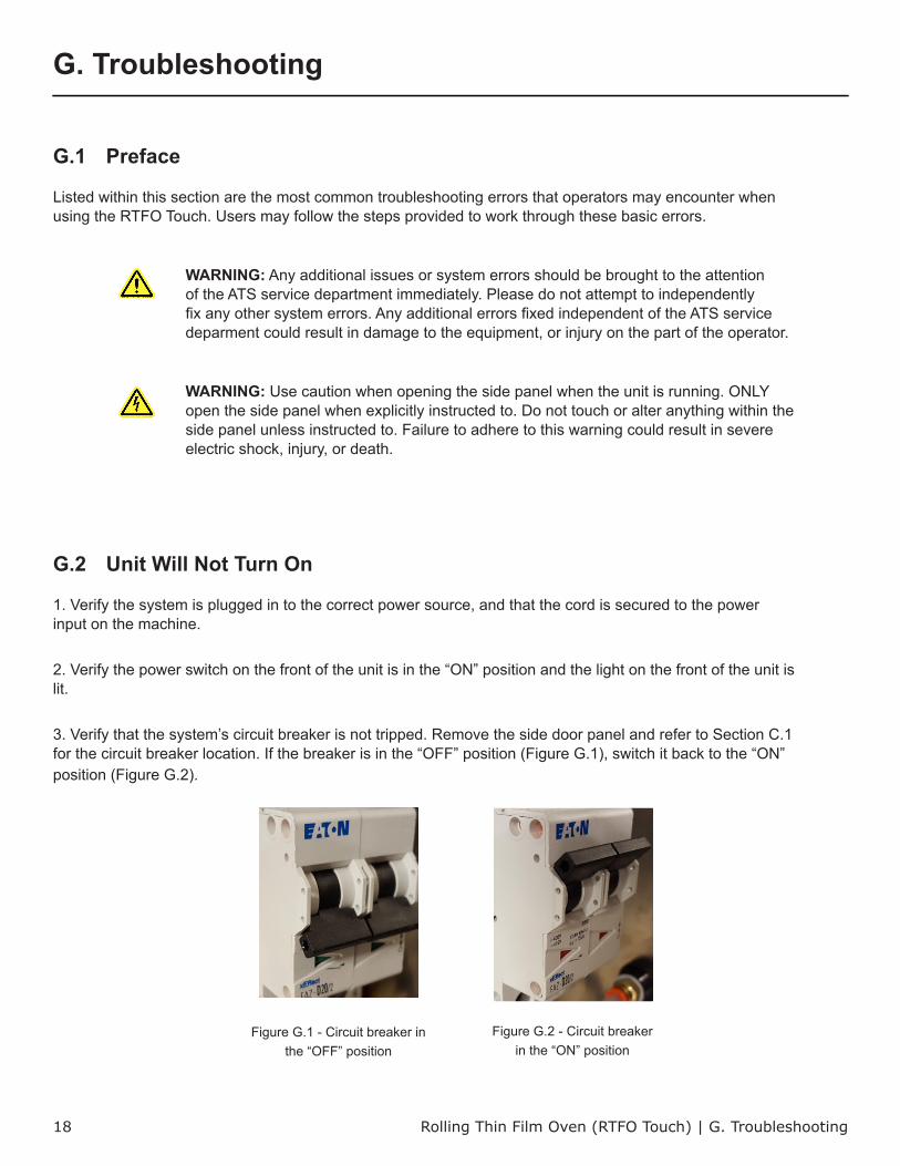
3. Verify that the system’s circuit breaker is not tripped. Remove the side door panel and refer to Section C.1for the circuit breaker location. If the breaker is in the “OFF” position (Figure G.1), switch it back to the “ON”position (Figure G.2).
Figure G.1 - Circuit breaker in the “OFF” position
Figure G.2 - Circuit breaker in the “ON” position
4. Verify the outlet is rated for the correct amperage (20 Amps).
5. If the unit still does not power on after checking each of these areas, please contact the ATS servicedepartment at +1-724-283-1212.
G.3 Unit Will Not Heat
1. Verify that there is power to the unit - refer to Section G.2.
2. If the unit still will not heat, open the side panel and refer to Section C.1 tolocate the temperature controller. If necessarry, adjust using the touchscreen.
3. If the unit still will not heat or the temperature controller will not turn on, openthe side panel and refer to Section C.1 to locate Fuses 5 & 6. These fuses controlthe Temperature Controller and Heaters. A light will indicate if the fuses are blownand need replaced. If the unit still will not heat after replacing the fuses, contactthe ATS service department by calling +1-724-283-1212.
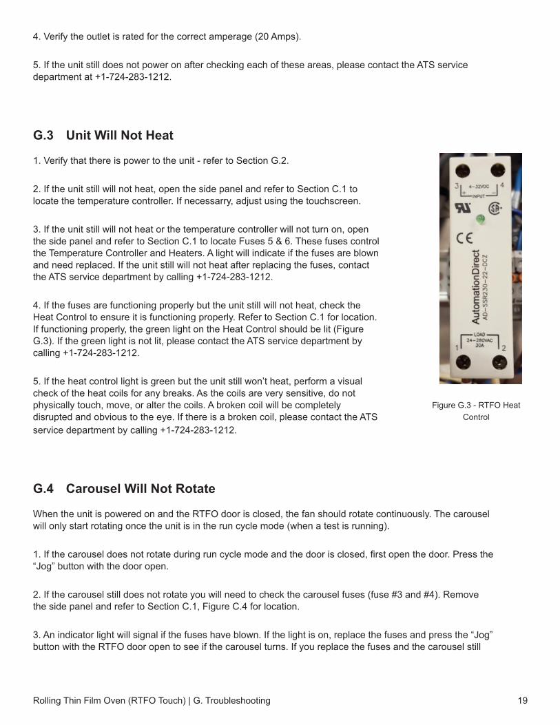
4. If the fuses are functioning properly but the unit still will not heat, check theHeat Control to ensure it is functioning properly. Refer to Section C.1 for location.If functioning properly, the green light on the Heat Control should be lit (FigureG.3). If the green light is not lit, please contact the ATS service department bycalling +1-724-283-1212.
5. If the heat control light is green but the unit still won’t heat, perform a visualcheck of the heat coils for any breaks. As the coils are very sensitive, do notphysically touch, move, or alter the coils. A broken coil will be completelydisrupted and obvious to the eye. If there is a broken coil, please contact the ATSservice department by calling +1-724-283-1212.
G.4 Carousel Will Not Rotate
When the unit is powered on and the RTFO door is closed, the fan should rotate continuously. The carousel will only start rotating once the unit is in the run cycle mode (when a test is running).
1. If the carousel does not rotate during run cycle mode and the door is closed, first open the door. Press the“Jog” button with the door open.
2. If the carousel still does not rotate you will need to check the carousel fuses (fuse #3 and #4). Removethe side panel and refer to Section C.1, Figure C.4 for location.
3. An indicator light will signal if the fuses have blown. If the light is on, replace the fuses and press the “Jog”button with the RTFO door open to see if the carousel turns. If you replace the fuses and the carousel still
Rolling Thin Film Oven (RTFO Touch) | G. Troubleshooting 19
Figure G.3 - RTFO Heat Control
does not turn, contact the ATS service department at +1-724-283-1212.
G.5 Fan Motor Will Not Rotate
When the unit is powered on and the RTFO door is closed, the fan should rotate continuously.
1. If the fan does not rotate you will need to check the fan fuses (fuse #1 and #2). Remove the side paneland refer to Section C.1, Figure C.4 for location.
3. An indicator light will signal if the fuses have blown. If the light is on, replace the fuses and see if the fanbegins to turn. If you replace the fuses and the fan still does not turn, contact the ATS service department at+1-724-283-1212.
G.6 Unit Has No Airflow
1. Verify that the supply air connection is secure in the rear of the machine, and that the air flow is set to thespecified setting on the Settings Screen.
2. If the air flow is set at the appropriate setting but the unit still has no air flow, you will need to remove theside panel and check the air regulator. Refer to Section C.1 for location.
3. Verify that the air regulator is set at 22-25 PSI. If it is not, adjust as needed.
4. If the unit still has no air flow, please contact the ATS service department at +1-724-283-1212.
Rolling Thin Film Oven (RTFO Touch) | G. Troubleshooting20
Rolling Thin Film Oven (RTFO Touch) | H. Maintenance 21
H. Maintenance
H.1 Cleaning the Unit
Before cleaning the RTFO, unplug the machine and allow it to cool. Always make sure to wear personal protective gear, and clean using Acetone. Do not use any other flammable solvents to clean this machine.
H.2 Greasing the Bearings
There are two bearings supporting the shaft of the carousel wheel that should be greased every six months with high temperature grease (Super Lube Synthetic Grease MFG#41150) or equivalent with a 260°C rating.
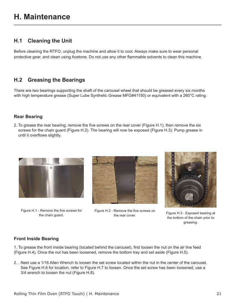
Rear Bearing
2. To grease the rear bearing, remove the five screws on the rear cover (Figure H.1), then remove the sixscrews for the chain guard (Figure H.2). The bearing will now be exposed (Figure H.3). Pump grease inuntil it overflows slightly.
Front Inside Bearing
1. To grease the front inside bearing (located behind the carousel), first loosen the nut on the air line feed(Figure H.4). Once the nut has been loosened, remove the bottom tray and set aside (Figure H.5).
2. . Next use a 1/16 Allen Wrench to loosen the set screw located within the nut in the center of the carousel.See Figure H.6 for location, refer to Figure H.7 to loosen. Once the set screw has been loosened, use a3/4 wrench to loosen the nut (Figure H.8).
Figure H.2 - Remove the five screws on the rear cover.
Figure H.1 - Remove the five screws for the chain guard. Figure H.3 - Exposed bearing at
the bottom of the chain prior to greasing.
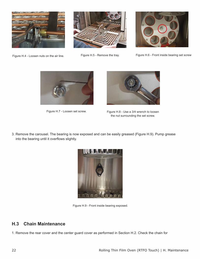
3. Remove the carousel. The bearing is now exposed and can be easily greased (Figure H.9). Pump greaseinto the bearing until it overflows slightly.
H.3 Chain Maintenance
1. Remove the rear cover and the center guard cover as performed in Section H.2. Check the chain for
Rolling Thin Film Oven (RTFO Touch) | H. Maintenance22
Figure H.9 - Front inside bearing exposed.
Figure H.7 - Loosen set screw. Figure H.8 - Use a 3/4 wrench to loosen the nut surrounding the set screw.
Figure H.6 - Front inside bearing set screwFigure H.4 - Loosen nuts on the air line. Figure H.5 - Remove the tray.
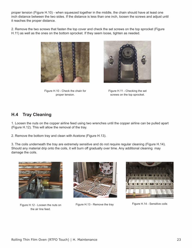
proper tension (Figure H.10) - when squeezed together in the middle, the chain should have at least one inch distance between the two sides. If the distance is less than one inch, loosen the screws and adjust until it reaches the proper distance.
2. Remove the two screws that fasten the top cover and check the set screws on the top sprocket (FigureH.11) as well as the ones on the bottom sprocket. If they seem loose, tighten as needed.
H.4 Tray Cleaning
1. Loosen the nuts on the copper airline feed using two wrenches until the copper airline can be pulled apart(Figure H.12). This will allow the removal of the tray.
2. Remove the bottom tray and clean with Acetone (Figure H.13).
3. The coils underneath the tray are extremely sensitive and do not require regular cleaning (Figure H.14).Should any material drip onto the coils, it will burn off gradually over time. Any additional cleaning maydamage the coils.
Rolling Thin Film Oven (RTFO Touch) | H. Maintenance 23
Figure H.10 - Check the chain for proper tension.
Figure H.11 - Checking the set screws on the top sprocket.
Figure H.14 - Sensitive coilsFigure H.12 - Loosen the nuts on the air line feed.
Figure H.13 - Remove the tray
Rolling Thin Film Oven (RTFO Touch) | H. Maintenance24
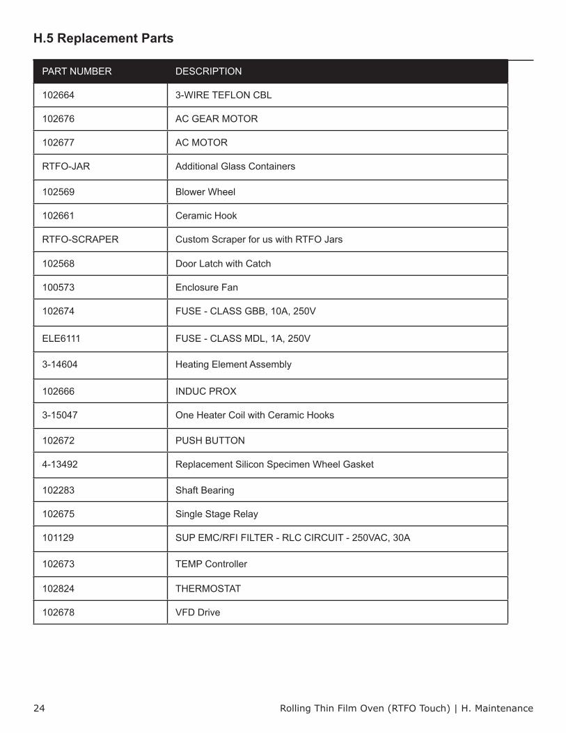
H.5 Replacement Parts
PART NUMBER DESCRIPTION
102664 3-WIRE TEFLON CBL
102676 AC GEAR MOTOR
102677 AC MOTOR
RTFO-JAR Additional Glass Containers
102569 Blower Wheel
102661 Ceramic Hook
RTFO-SCRAPER Custom Scraper for us with RTFO Jars
102568 Door Latch with Catch
100573 Enclosure Fan
102674 FUSE - CLASS GBB, 10A, 250V
ELE6111 FUSE - CLASS MDL, 1A, 250V
3-14604 Heating Element Assembly
102666 INDUC PROX
3-15047 One Heater Coil with Ceramic Hooks
102672 PUSH BUTTON
4-13492 Replacement Silicon Specimen Wheel Gasket
102283 Shaft Bearing
102675 Single Stage Relay
101129 SUP EMC/RFI FILTER - RLC CIRCUIT - 250VAC, 30A
102673 TEMP Controller
102824 THERMOSTAT
102678 VFD Drive
Rolling Thin Film Oven (RTFO Touch) | APPENDIX A: Warranty25
APPENDIX A: Warranty
Your Applied Test Systems product has been manufactured and inspected by experienced craftsmen. Applied Test Systems warrants, for the original purchaser, each product to be free from defects in material and workmanship for a period of thirteen (13) months from date of shipment or twelve (12) months from date of installation - whichever comes first. This warranty does not apply to failures caused by normal usage, misuse, or repair or service by unauthorized personnel, nor does it cover limited life electrical components which deteriorate with age such as tubes, lamps, fuses, and heaters. Load cells are covered for manufactured defects only - incidents of over load or other customer misuse are not covered under warranty. The warranty does not extend to products not manufactured or assembled by Applied Test Systems.
This warranty is expressly limited to the repair, replacement, or adjustment of the product at Applied Test Systems’ option. The product must be returned to the Applied Test Systems factory or an authorized repair center. Applied Test Systems shall not be liable for any labor, transportation, or installation costs that may arise in connection with the product or return.
To obtain warranty service:
1. Applied Test Systems must be promptly notified in writing of the defect.
2. Upon receipt of written authorization, said defective equipment is returned as directed, with transportationcharges prepaid by the buyer and –
3. Applied Test Systems examination of such equipment discloses to its satisfaction that the defect exists andwas not caused by negligence, misuse, improper installation, accident, or unauthorized repair or alteration.
This warranty is in lieu of all other warranties, expressed or implied, including the implied warranty of merchantability or fitness for particular purpose. In no event shall Applied Test Systems be liable for direct, indirect, special, incidental, collateral, or consequential damages.
The aforementioned provisions do not extend the original warranty period of any article that has been either repaired or replaced by Applied Test Systems.
Applied Test Systems reserves the right to change published specifications.
Rolling Thin Film Oven (RTFO Touch) | APPENDIX B: Wiring Diagram 26
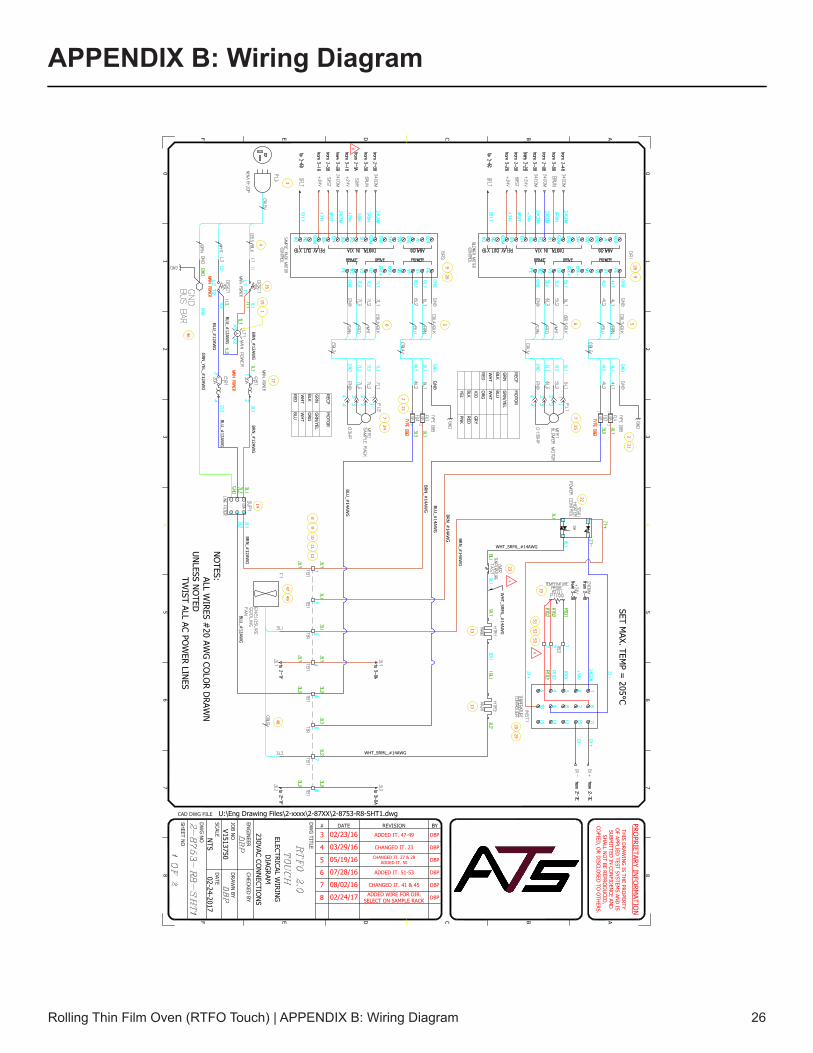
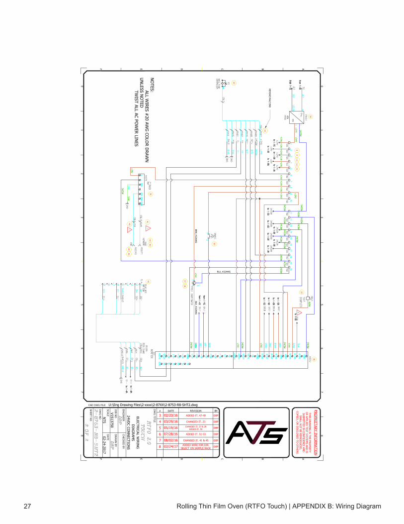
APPENDIX B: Wiring Diagram
BYREVISION# DATE
DW
G TITLE
CHECKED
BY
DRAW
N BY
DATE
ENG
INEER
JOB N
O
DW
G N
O
CAD DWG FILE
SCALE
SHEET N
O
PROPRIETARY IN
FORM
ATION
THIS D
RAWIN
G IS TH
E PROPERTY
OF APPLIED
TEST SYSTEMS AN
D IS
SUBM
ITTED IN
CON
FIDEN
CE AND
SHALL N
OT BE REPRO
DU
CED,
COPIED
, OR D
ISCLOSED
TO O
THERS.
0 0
1 1
2 2
3 3
4 4
5 5
6 6
7 7
8 8
ABCDEF
ABCDEF02-24-2017
U:\Eng Drawing Files\2-xxxx\2-87XX\2-8753-R8-SHT1.dwg
V1513750
NTS
ELECTRICAL WIRIN
GD
IAGRAM
230VAC CON
NECTIO
NS
BRN_#
12AWG
BLU_#
12AWG
BLU_#
12AWG
GRN
_YEL_#12AW
G
BRN_#
12AWG
BLU_#
12AWG
BRN_#
12AWG
BLU_#
12AWG
BLU_#
14AWG
BRN_#
14AWG
BLU_#
14AWG
BRN_#
14AWG BRN
_#14AW
G
WHT_SRML_#14AWG
WHT_SRML_#14AWGNO
TES:ALL WIRES #
20 AWG
COLO
R DRAW
NU
NLESS N
OTED
TWIST ALL AC PO
WER LIN
ES
WH
T_SRML_#
14AWG
3
416
15
17
14
8
23
1313
19
2225
5624
21
26
6 526
911
1210
2
212
9
9
1
7 7
46
4749
48
3 02/23/16 ADDED IT. 47-49 DBP
RECPM
OTO
R
GRN
GRN
/YEL
BLKBLU
WH
TW
HT
REDO
RG
VIOG
RY
BLKRED
YELPN
K
RECPM
OTO
R
GRN
GRN
/YEL
BLKO
RG
WH
TW
HT
REDBLU
SET MAX. TEM
P = 205°C
4 03/29/16 CHANGED IT. 23 DBP
4
5 05/19/16 CHANGED IT. 27 & 28ADDED IT. 50 DBP
2029
5152
53
6 07/28/16 ADDED IT. 51-53 DBP
6
7 08/02/16 CHANGED IT. 41 & 45 DBP
8 02/24/17 ADDED WIRE FOR DIR.SELECT ON SAMPLE RACK DBP
8
Rolling Thin Film Oven (RTFO Touch) | APPENDIX B: Wiring Diagram27
BYREVISION# DATE
DW
G TITLE
CHECKED
BY
DRAW
N BY
DATE
ENG
INEER
JOB N
O
DW
G N
O
CAD DWG FILE
SCALE
SHEET N
O
PROPRIETARY IN
FORM
ATION
THIS D
RAWIN
G IS TH
E PROPERTY
OF APPLIED
TEST SYSTEMS AN
D IS
SUBM
ITTED IN
CON
FIDEN
CE AND
SHALL N
OT BE REPRO
DU
CED,
COPIED
, OR D
ISCLOSED
TO O
THERS.
0 0
1 1
2 2
3 3
4 4
5 5
6 6
7 7
8 8
ABCDEF
ABCDEF02-24-2017
U:\Eng Drawing Files\2-xxxx\2-87XX\2-8753-R8-SHT2.dwg
V1513750
NTS
ELECTRICAL WIRIN
GD
IAGRAM
S24VD
C CON
NECTIO
NS
2728
30
32
34
811
931
12
18
38
3641
NO
TES:ALL WIRES #
20 AWG
COLO
R DRAW
NU
NLESS N
OTED
TWIST ALL AC PO
WER LIN
ES
REMO
VE MALE EN
D
4440
42
4544
40
3 02/23/16 ADDED IT. 47-49 DBP
4 03/29/16 CHANGED IT. 23 DBP
BRN_#
22AWG
BLK_#22AW
G
BLU_#22AWG
5 05/19/16 CHANGED IT. 27 & 28ADDED IT. 50 DBP
50
6 07/28/16 ADDED IT. 51-53 DBP
7 08/02/16 CHANGED IT. 41 & 45 DBP
7
7
8 02/24/17 ADDED WIRE FOR DIR.SELECT ON SAMPLE RACK DBP
8

APPENDIX C: Image Glossary
Figure A.1 - ATS Sample Data Tag ............................................................................................................................. 1Figure C.1 - RTFO Touch Front .................................................................................................................................. 5Figure C.2 - RTFO Touch Back .................................................................................................................................. 6Figure C.3 - RTFO Touch Chamber ........................................................................................................................... 7Figure C.4 - Panel Layout & Components .................................................................................................................. 8Figure D.1 - Power Switch in the OFF Position ........................................................................................................ 10Figure D.2 - Power Switch in the ON Position .......................................................................................................... 10Figure D.3 - RTFO Female Air Connection .............................................................................................................. 10Figure D.4 - IP Address and Password, View Screen ...............................................................................................11Figure F.1 - RTFO Touch Software Screen Map ...................................................................................................... 13Figure F.2 - Main Screen .......................................................................................................................................... 14Figure F.3 - View Screen .......................................................................................................................................... 14Figure F.4 - Language Screen .................................................................................................................................. 14Figure F.5 - Settings Screen ..................................................................................................................................... 14Figure F.6 - Status Bar, Preheat Delay State............................................................................................................ 15Figure F.7 - Main Screen - Preheat .......................................................................................................................... 16Figure F.8 - Main Screen - Load Samples ................................................................................................................ 17Figure F.9 - Main Screen - Cycle Finished ............................................................................................................... 17Figure G.1 - Circuit Breaker in the “OFF” Position ................................................................................................... 18Figure G.2 - Circuit Breaker in the “ON” Position ..................................................................................................... 18Figure G.3 - RTFO Heat Control .............................................................................................................................. 19Figure H.1 - Remove the Five Screws for the Chain Guard. ................................................................................... 21Figure H.2 - Remove the Five Screws on the Rear Cover. ...................................................................................... 21Figure H.3 - Exposed Bearing at the Bottom of the Chain Prior to Greasing. .......................................................... 21Figure H.4 - Loosen Nuts on the Air Line. ................................................................................................................ 22Figure H.5 - Remove the Tray. ................................................................................................................................. 22Figure H.6 - Front Inside Bearing Set Screw ............................................................................................................ 22Figure H.7 - Loosen Set Screw................................................................................................................................. 22Figure H.8 - Use a 3/4 Wrench to Loosen the Nut Surrounding the Set Screw. ....................................................... 22Figure H.9 - Front Inside Bearing Exposed. ............................................................................................................. 22Figure H.10 - Check the Chain for Proper Tension. .................................................................................................. 23Figure H.11 - Checking the Set Screws on the Top Sprocket. .................................................................................. 23Figure H.12 - Loosen the Nuts on the Air Line Feed. ............................................................................................... 23Figure H.13 - Remove the tray ................................................................................................................................. 23Figure H.14 - Sensitive Coils .................................................................................................................................... 23
Rolling Thin Film Oven (RTFO Touch) | APPENDIX C: Image Glossary 28