Embed Size (px)
Citation preview
1Mbaaacbdostlcwwhts
frc[taCpscspsi
I. Chremmos and N. Uzunoglu Vol. 25, No. 12 /December 2008 /J. Opt. Soc. Am. A 3043
Modes of the infinite square lattice of coupledmicroring resonators
Ioannis Chremmos* and Nikolaos Uzunoglu
Microwave and Fiber Optics Laboratory, School of Electrical and Computer Engineering, National TechnicalUniversity of Athens, 9 Iroon Polytechniou Street, Zografos 15780, Athens, Greece
*Corresponding author: [email protected]
Received September 16, 2008; accepted October 14, 2008;posted October 17, 2008 (Doc. ID 101622); published November 19, 2008
The infinite square lattice of coupled microring optical resonators is studied for what we belive to be the firsttime. Using the standard matrix formalism and the classical Bloch’s theorem for propagation in periodic opti-cal media, the dispersion equation and the amplitudes of propagating Bloch modes are derived analytically. Itis found that the dispersion equation ��kx ,ky� of this 2D microring array is expressed as the sum of two inde-pendent dispersion equations of the 1D microring array with wavenumbers kx and ky. As a result, the width ofthe passband is twice that of a microring coupled-resonator optical waveguide and there are no stop bands foran interresonator power coupling ratio greater than 1/2. The evanescent modes that are important to theanalysis of lattices with interrupted periodicity are also studied. The reported analysis is the prerequisite tothe future study of superresonators consisting of large finite microring arrays. © 2008 Optical Society ofAmerica
OCIS codes: 130.5296, 130.3120, 140.4780, 230.4555, 230.5298, 230.5750.
miftcM
stcdsT(elct
ramifiai[fIttctC
. INTRODUCTIONicroring resonators are recognized as fundamental
uilding blocks for optical signal processing and routingpplications. Optical filters with a desired amplitudend/or phase response are composed of multiring systemsnd bus waveguides with the involved coupling coeffi-ients and optical path lengths selected appropriately byorrowing techniques from the theory of electronic filteresign [1–3]. The established filter architectures consistf linear arrays of microrings, which are coupled eithererially (directly) [4,5] or in parallel (indirectly) throughwo adjacent waveguides [6,7]. In related configurations,ong periodic chains of serially coupled microrings createoupled-resonator optical waveguides (CROWs) [8], alonghich light propagates at low and tunable group velocity,hich is a key feature for creating delay lines [9] and en-ancing nonlinear effects [10]. Similar effects are ob-ained in periodic arrays of directly uncoupled microringside coupled to an adjacent bus waveguide [11].
The literature shows that nearly all of the work done soar on multiring devices has focused on 1D microring ar-ays. However, the technological ability to integrate mi-roring resonators on photonic chips at very large scales12,13] inevitably stimulates interest to explore new mul-iring architectures that expand in 2D. A few papers havelready been published, paving the way in this direction.losed loops of serially coupled microrings have been pro-osed to form superresonator structures with interestingpectral properties [14,15]. A 2D array of mutuallyoupled microrings was analyzed in [16], and it washown that a 2�N array with appropriately selected cou-ling coefficients can have a 2Nth-order elliptic filter re-ponse. Within a different scope, a 2�N array of micror-ngs can work as a directional coupler of two parallel
1084-7529/08/123043-8/$15.00 © 2
icroring CROWs with tunable spectral behavior [17]. Annteresting concept to combine complementary spectraleatures of serially and parallel coupled microring filteropologies was also proposed in [18] using a 2D M�N mi-roring array composed of N parallel coupled columns of
serially coupled microrings.This paper aims to contribute to the same direction by
tudying theoretically the most fundamental multiringopology in 2D, which is the infinite square lattice ofoupled microring resonators. Square lattices of holes in aielectric substrate or dielectric rods in air are well-tudied geometries in the area of photonic crystals [19].his is also true for finite 2D arrays of whispering gallery
WG) microdisks forming photonic molecules [20]. How-ver, to the best of our knowledge, there has been no pub-ished study of propagation in a periodic 2D lattice of mi-roring resonators, which is essentially the extension ofhe concept of the 1D CROW in 2D.
Using the standard matrix formalism and Bloch’s theo-em for propagation in periodic optical media, the presentnalysis derives analytically the dispersion equation andode amplitudes of propagating Bloch waves. The travel-
ng wave nature of microring resonators requires a modi-cation to the standard way for applying Bloch’s theorem,nd it is proved that the phase difference between fieldsn neighbor resonators is not kx,y� as in the 1D CROW21] but contains an extra term that depends on the dif-erence between the wavenumbers in directions x and y.t is also found that the dispersion equation ��kx ,ky� ofhe periodic 2D microring array structure is expressed ashe sum of two independent dispersion equations of a mi-roring CROW with wavenumbers kx and ky. As a result,he width of the passband is twice that of a microringROW, and there are no stop bands for an interresonator
008 Optical Society of America
pptrcFiwiatp
2AFsEwa��rwniccacm=p
e
ifa
wwt=sdtdsttftgaew
ms
aw
tuklpstmcpqfqrt
wt
tp
Fwp
3044 J. Opt. Soc. Am. A/Vol. 25, No. 12 /December 2008 I. Chremmos and N. Uzunoglu
ower coupling ratio greater than 1/2 due to the overlap-ing passbands of successive microring resonances. Also,he components of the group velocity along the x and y di-ections are equal to the group velocity of a mode in a mi-roring CROW with wavenumbers kx and ky, respectively.inally, the evanescent modes of the lattice are also stud-
ed through an elegant graphical approach. These modesith complex wavenumbers can exist only in lattices with
nterrupted periodicity and are therefore important to thenalysis of lattice defects or phenomena at the interface ofhe lattice with another medium, which are present in allractical architectures.
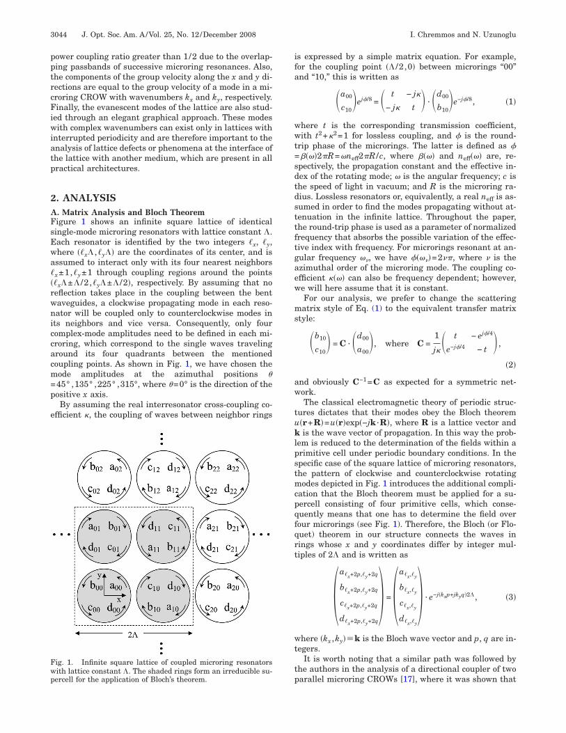
. ANALYSIS. Matrix Analysis and Bloch Theoremigure 1 shows an infinite square lattice of identicalingle-mode microring resonators with lattice constant �.ach resonator is identified by the two integers �x, �y,here ��x� ,�y�� are the coordinates of its center, and isssumed to interact only with its four nearest neighborsx±1,�y±1 through coupling regions around the points�x�±� /2 ,�y�±� /2�, respectively. By assuming that noeflection takes place in the coupling between the bentaveguides, a clockwise propagating mode in each reso-ator will be coupled only to counterclockwise modes in
ts neighbors and vice versa. Consequently, only fouromplex-mode amplitudes need to be defined in each mi-roring, which correspond to the single waves travelinground its four quadrants between the mentionedoupling points. As shown in Fig. 1, we have chosen theode amplitudes at the azimuthal positions �45° ,135° ,225° ,315°, where �=0° is the direction of theositive x axis.By assuming the real interresonator cross-coupling co-
fficient �, the coupling of waves between neighbor rings
ig. 1. Infinite square lattice of coupled microring resonatorsith lattice constant �. The shaded rings form an irreducible su-ercell for the application of Bloch’s theorem.
s expressed by a simple matrix equation. For example,or the coupling point �� /2 ,0� between microrings “00”nd “10,” this is written as
�a00
c10�ej�/8 = � t − j�
− j� t � · �d00
b10�e−j�/8, �1�
here t is the corresponding transmission coefficient,ith t2+�2=1 for lossless coupling, and � is the round-
rip phase of the microrings. The latter is defined as �����2�R=�neff2�R /c, where ���� and neff��� are, re-pectively, the propagation constant and the effective in-ex of the rotating mode; � is the angular frequency; c ishe speed of light in vacuum; and R is the microring ra-ius. Lossless resonators or, equivalently, a real neff is as-umed in order to find the modes propagating without at-enuation in the infinite lattice. Throughout the paper,he round-trip phase is used as a parameter of normalizedrequency that absorbs the possible variation of the effec-ive index with frequency. For microrings resonant at an-ular frequency �, we have ����=2�, where is thezimuthal order of the microring mode. The coupling co-fficient ���� can also be frequency dependent; however,e will here assume that it is constant.For our analysis, we prefer to change the scatteringatrix style of Eq. (1) to the equivalent transfer matrix
tyle:
�b10
c10� = C · �d00
a00�, where C =
1
j�� t − ej�/4
e−j�/4 − t � ,
�2�
nd obviously C−1=C as expected for a symmetric net-ork.The classical electromagnetic theory of periodic struc-
ures dictates that their modes obey the Bloch theorem�r+R�=u�r�exp�−jk ·R�, where R is a lattice vector andis the wave vector of propagation. In this way the prob-
em is reduced to the determination of the fields within arimitive cell under periodic boundary conditions. In thepecific case of the square lattice of microring resonators,he pattern of clockwise and counterclockwise rotatingodes depicted in Fig. 1 introduces the additional compli-
ation that the Bloch theorem must be applied for a su-ercell consisting of four primitive cells, which conse-uently means that one has to determine the field overour microrings (see Fig. 1). Therefore, the Bloch (or Flo-uet) theorem in our structure connects the waves inings whose x and y coordinates differ by integer mul-iples of 2� and is written as
�a�x+2p,�y+2q
b�x+2p,�y+2q
c�x+2p,�y+2q
d�x+2p,�y+2q
� = �a�x,�y
b�x,�y
c�x,�y
d�x,�y
� · e−j�kxp+jkyq�2�, �3�
here �kx ,ky��k is the Bloch wave vector and p, q are in-egers.
It is worth noting that a similar path was followed byhe authors in the analysis of a directional coupler of twoarallel microring CROWs [17], where it was shown that

tpposCops
�Tns
Ibeocad
U
wmP
Wasfi
w
Nttdtf
I. Chremmos and N. Uzunoglu Vol. 25, No. 12 /December 2008 /J. Opt. Soc. Am. A 3045
he Bloch condition has its familiar form only if it is ap-lied over two lattice periods, while it is modified by theresence of an extra phase shift of alternating sign overne lattice period. In Subsection 2.D it is proved that aimilar result is also valid for the 2D lattice of microrings.onclusively, in both cases the rotating modes follow a 1Dr 2D periodic pattern of “modal” periodicity, which has asrimitive vector(s) twice the primitive vector(s) of thetructural periodicity, i.e., 2�x ,2�y, instead of �x ,�y.
The mode amplitudes in the four resonators of the 2�2� supercell constitute a set of 16 unknown variables.hese are connected through linear equations of equalumber arising from the eight coupling points lying in theupercell:
�b10
c10� = C · �d00
a00� , �4.1�
� c01
d01� = C · �a00
b00� , �4.3�
�d11
a11� = C · �b01
c01� , �4.5�
�a11
b11� = C · � c10
d10� , �4.7�
�d10
a10� = C · �b00
c00�e−j2kx�, �4.2�
�a01
b01� = C · � c00
d00�e−j2ky�, �4.4�
�b11
c11� = C · �d01
a01�e−j2kx�, �4.6�
� c11
d11� = C · �a10
b10�e−j2ky�. �4.8�
n Eqs. (4.2), (4.4), (4.6), and (4.8), Bloch condition (3) haseen used as the periodic boundary condition in order toliminate the wave amplitudes of the microrings lyingutside the supercell. Equations (4) can obtain a moreompact look by defining the following 4�4 matrices ofmplitude transmission between neighbor microrings in
irections x and y: Tai
Bfo
Tx =1
j��0 e−j�/4 − t 0
− ej�/4 0 0 t
− t 0 0 e−j�/4
0 t − ej�/4 0�, Ty = �0 C
C 0� .
�5�
sing definitions (5), Eqs. (4) are compactly written as
w10 = TxPxw00, �6.1�
w11 = TyPyw10, �6.3�
w01 = TyPy−1e−j2ky�w00, �6.2�
w11 = TxPx−1e−j2kx�w01. �6.4�
here w�x�y��a�x�y
,b�x�y,c�x�y
,d�x�y�T is the 4�1 vector of
ode amplitudes in the corresponding resonator andx ,Py are diagonal matrices of phase factors
Px = �1 0 0 0
0 e−j2kx� 0 0
0 0 e−j2kx� 0
0 0 0 1� ,
Py = �e−j2ky� 0 0 0
0 e−j2ky� 0 0
0 0 1 0
0 0 0 1� . �7�
hen Eqs. (6.1) and (6.2) are substituted into Eqs. (6.3)nd (6.4), respectively, we obtain the final homogeneousystem that has to be satisfied by Bloch modes of the in-nite lattice in the absence of excitation:
M�kx,ky,�� · w00 = 0. �8�
he matrix of the system is given by
M�kx,ky,�� = TyPyTxPx − TxPx−1TyPy
−1e−j2�kx+ky�� = �0 − Pkx
� Qkx,ky
� Pky
−�
− Pkx
−� 0 Pky
� e−j2kx� Q−kx,ky
−� e−j2kx�
− Qkx,ky
−� Pky
−�e−j2kx� 0 − Pkx
� e−j2ky�
Pky
� − Q−kx,ky
� e−j2kx� − Pkx
−�e−j2ky� 0� , �9�
here we have defined
Pkx,y
� = tej�/4�1 + e−j2kx,y��,
Qkx,ky
� = ej��/2−2kx�� − e−j��/2+2ky��. �10�
ontrivial solutions �w00�0� of system (8) have to satisfyhe zero determinant condition �M�=0, which is essen-ially the condition for propagation that will reveal theispersion equation ��kx ,ky� of Bloch modes. After doinghe necessary algebra, the determinant of matrix M isound:
�M� =16
�8 e−j�kx+ky�2�sin4��/2� − 2�2 sin2��/2�
�cos2�kx�� + cos2�ky�� − 2�2 cos2�kx��cos2�ky���
+ �4cos2�kx�� − cos2�ky���2�, �11�
nd the condition �M�=0 is easily solved for sin�� /2�, giv-ng
sin��/2� = ± � cos�kx�� 1 − �2 cos2�ky��
± � cos�ky�� 1 − �2 cos2�kx��. �12�
y naming ��kx ,ky� the dispersion equation resultingrom Eq. (12) for the (,) signs, it is obvious that thether three combinations (�,), (,�), and (�,�) yield

t�2attt�
n
wmpcnm
wvf1�cav�sicqatrf=aisa
BIptiwmapt�−maB
tf
s�t−i�bBcnvtcbrc
bfi=g=magoa
prtFrpasbb
CIrfi
Fnn�
3046 J. Opt. Soc. Am. A/Vol. 25, No. 12 /December 2008 I. Chremmos and N. Uzunoglu
he shifted functions ��kx−� /� ,ky�, ��kx ,ky−� /��, and�kx−� /� ,ky−� /��. As will be explained in Subsection.C, the four equations yield exactly the same mode fieldsnd are therefore different forms of the dispersion equa-ion of the same mode. Hence, all properties of propaga-ion can be obtained by studying the case (,), which ishe one that gives positive group velocity components� /�kx, �� /�ky in the first quadrant of the Brillouin zone.
At this point we introduce the particularly useful defi-ition of phase ��K� as
sin��K�/2� = − � cos�K��, �13�
hich is essentially the dispersion equation of an infiniteicroring CROW [8,21], with � being the round-trip
hase of the microrings, K the wavenumber, and � theoupling coefficient between successive resonators. Defi-ition (13) allows us to write dispersion Eq. (12) in the re-arkably simple form
����� = ��kx� + ��ky�, �14�
here �����=����−����. Note that it is convenient toiew function ����� as a normalized frequency detuningrom resonance because, in most practical cases, this is a−1 function of ��=�−�0. When ��—and consequently�—is small enough to justify the assumption of a fairlyonstant effective index neff����neff���, we can furtherpproximate ���2��� /�. Equation (14) expresses theery interesting conclusion that the dispersion equation�kx ,ky� of the square microring lattice is equal to theum of two independent dispersion equations of a micror-ng CROW with the same interresonator coupling coeffi-ient and wavenumbers kx and ky. Equivalently, the fre-uency detuning of a Bloch mode of the 2D microringrray with wave vector k= �kx ,ky� is equal to the sum ofhe frequency detunings of modes of the 1D microring ar-ay with wavenumbers kx and ky. A direct corollary of thisact is that, since �� /�kx=d��kx� /dkx and �� /�kyd��ky� /dky, the components of group velocity along the xnd y directions are equal to the group velocity of a moden a microring CROW with wavenumbers kx and ky, re-pectively. The band structure resulting from Eq. (14) isnalyzed in Subsection 2.B.
. Band Structuren order to find the frequency bands that permit lightropagation along the microring lattice, one seeks the ex-rema of the dispersion function ���kx ,ky�. From Eq. (14)t is evident that �� becomes maximum or minimumhen both functions ��kx� ,��ky� take their maximum orinimum value, 2�c and −2�c, respectively, where the
ngle �c=sin−1��� is an alternative measure of the cou-ling strength between the microrings. Consequently, ��akes its maximum value 4�c for wavenumberskx� ,ky��= ��+2m� ,�+2n�� and its minimum value4�c for wavenumbers �kx� ,ky��= �2m� ,2n��, where,n are independent integers. Bloch modes are therefore
llowed to propagate within a round-trip phase span ofc=8�c radians around the central resonant frequency �.There are two cases, depending on the relationship be-
ween the normalized bandwidth Bc and the normalizedree spectral range of FSR=2� radians between succes-
ive microring resonances ����+1�−����=2��: (a) Whenc � /4, or equivalently �2 1/2, we have Bc FSR andhere is a frequency window of normalized width FSRBc=2�−8�c in the FSR between two successive micror-
ng resonances, where there are no real wave vectorskx ,ky� satisfying Eq. (14). This interval forms a stopand. (b) When �c�� /4, or equivalently �2�1/2, we havec�FSR. In that case, the passbands of successive mi-
roring resonances overlap over a frequency window withormalized width Bc−FSR=8�c−2�, centered at thealue �=����+�. There are therefore no stop bands, andhe lattice is transmissive at all frequencies. The previousonclusions are illustrated in Fig. 2, which maps the pass-ands of three successive microring resonances in theound-trip phase domain versus the interresonator poweroupling ratio �2.
An example of the dispersion function ���kx ,ky� giveny Eq. (14) is shown in Fig. 3(a) for wave vectors in therst Brillouin zone and �=0.6. The global minimum ��−4�c occurs at the center �kx ,ky�= �0,0� (� point) and thelobal maxima ��=4�c at the corners �kx� ,ky���±� , ±�� of the first Brillouin zone (M points). Theiddle points of the faces of the Brillouin zone (X points)
re saddle points. The corresponding isofrequency dia-ram is shown in Fig. 3(b). At the resonant frequency �
f the microring ���=0�, the isofrequency curve degener-tes to the square �kx��+ �ky��=�.It is always helpful to draw the dispersion equation of a
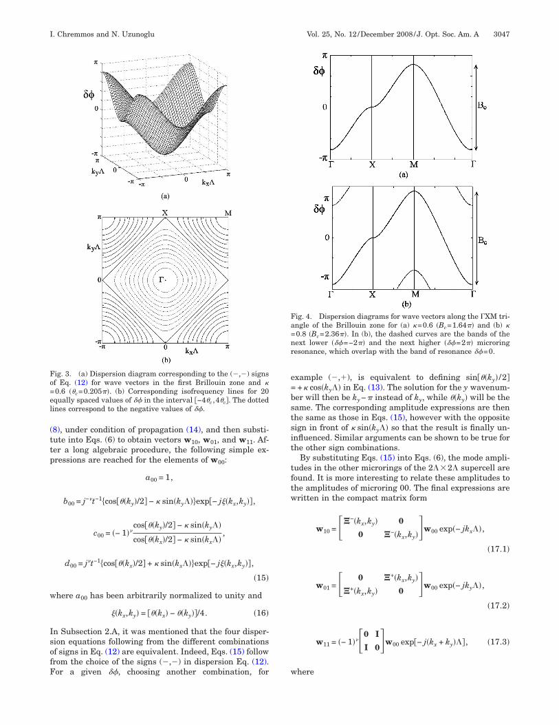
eriodic structure for wave vectors on the edges of the ir-educible part of the Brillouin zone, where the extrema ofhe frequency bands exist. Two examples are shown inigs. 4(a) and 4(b) for wave vectors along the standard ir-educible triangle �XM of the square lattice and the cou-ling coefficients �=0.6 and �=0.8, which fall under thebove cases (a) and (b), respectively. In Fig. 4(b), one canee the frequency overlap of the lower (higher) part of theand of resonance with the higher (lower) part of theand of resonance −1 �+1�.
. Wave Amplitudesn order to determine the amplitudes of the waves in theesonators of the 2��2� supercell (Fig. 1), one has tond the nontrivial solutions w00 of homogeneous system
ig. 2. Map of passbands of three successive microring reso-ances with azimuthal orders −1, , +1 versus the interreso-ator power coupling ratio �2. The overlap of passbands for �2
0.5 results in the absence of stop bands.
(ttp
w
IsofF
e=bstsit
tftw
w
Fo=el
Fa=nr
I. Chremmos and N. Uzunoglu Vol. 25, No. 12 /December 2008 /J. Opt. Soc. Am. A 3047
8), under condition of propagation (14), and then substi-ute into Eqs. (6) to obtain vectors w10, w01, and w11. Af-er a long algebraic procedure, the following simple ex-ressions are reached for the elements of w00:
a00 = 1,
b00 = j−t−1cos��ky�/2� − � sin�ky���exp− j��kx,ky��,
c00 = �− 1�cos��ky�/2� − � sin�ky��
cos��kx�/2� − � sin�kx��,
d00 = jt−1cos��kx�/2� + � sin�kx���exp− j��kx,ky��,
�15�
here a00 has been arbitrarily normalized to unity and
��kx,ky� = ��kx� − ��ky��/4. �16�
n Subsection 2.A, it was mentioned that the four disper-ion equations following from the different combinationsf signs in Eq. (12) are equivalent. Indeed, Eqs. (15) followrom the choice of the signs (,) in dispersion Eq. (12).or a given ��, choosing another combination, for
ig. 3. (a) Dispersion diagram corresponding to the (,) signsf Eq. (12) for wave vectors in the first Brillouin zone and �0.6 ��c=0.205��. (b) Corresponding isofrequency lines for 20qually spaced values of �� in the interval −4�c ,4�c�. The dottedines correspond to the negative values of ��.
xample (,�), is equivalent to defining sin��ky� /2�+� cos�ky�� in Eq. (13). The solution for the y wavenum-er will then be ky−� instead of ky, while ��ky� will be theame. The corresponding amplitude expressions are thenhe same as those in Eqs. (15), however with the oppositeign in front of � sin�ky�� so that the result is finally un-nfluenced. Similar arguments can be shown to be true forhe other sign combinations.
By substituting Eqs. (15) into Eqs. (6), the mode ampli-udes in the other microrings of the 2��2� supercell areound. It is more interesting to relate these amplitudes tohe amplitudes of microring 00. The final expressions areritten in the compact matrix form
w10 = ��−�kx,ky� 0
0 �−�kx,ky��w00 exp�− jkx��,
�17.1�
w01 = � 0 �+�kx,ky�
�+�kx,ky� 0 �w00 exp�− jky��,
�17.2�
w11 = �− 1��0 I
I 0�w00 exp− j�kx + ky���, �17.3�
here
ig. 4. Dispersion diagrams for wave vectors along the �XM tri-ngle of the Brillouin zone for (a) �=0.6 �Bc=1.64�� and (b) �0.8 �Bc=2.36��. In (b), the dashed curves are the bands of theext lower ���=−2�� and the next higher ���=2�� microringesonance, which overlap with the band of resonance ��=0.

�
a
swns±wtcd
cgfe=FfDtv
DSgcmsielteitwl
tcbt2cespstfiinF=oi
FW
Ffcsk
3048 J. Opt. Soc. Am. A/Vol. 25, No. 12 /December 2008 I. Chremmos and N. Uzunoglu
±�kx,ky�
= � 0 exp+ j��kx,ky� ± j�/2�
exp− j��kx,ky� � j�/2� 0 ��18�
nd I is the unitary matrix.Equations (17.1) and (17.2) prove the allegation of Sub-
ection 2.A that, in this periodic 2D lattice of travelingave resonators, the phase difference between fields ineighbor resonators is not equal to kx� or ky� as in thetandard Bloch condition, but contains an extra term��kx ,ky�±� /2, which depends on the difference betweenavenumbers kx ,ky [see Eq. (16)]. Also, Eq. (17.3) shows
hat the phase difference between the fields in nonadja-ent resonators of the same supercell is given by the stan-ard Bloch condition with an additional sign �−1�.Another conclusion derived from Eqs. (17) is that, in all
oupling points, the mode power entering the coupling re-ion in one microring is equal to the mode power exitingrom the coupling region in the adjacent microring. Forxample, from Eq. (17.1) it follows that b10a00 exp−j��kx ,ky�+ j� /2�, which means that �b10�= �a00�.igure 5 illustrates the distribution of mode power in the
our microrings of a 2��2� supercell for an arbitrary ��.iagrams of the mode powers given by Eqs. (15) versus
he involved wavenumbers are given in Fig. 6 for differentalues of coupling coefficient �.
. Evanescent Modeso far the analysis has focused on the modes that propa-ate along the microring lattice without attenuation. Ac-ording to the standard terminology of periodic opticaledia, termed photonic crystals, these are the “extended
tates” of the crystal that can rigorously exist only in thedeal infinite structure. In addition to these modes, thequation of propagation accepts complex wavenumber so-utions, which correspond to evanescent modes. In con-rast to the extended states, the evanescent states havexponentially varying amplitude and therefore cannot ex-st in an infinite lattice. They appear only when the lat-ice geometry is interrupted, as happens at an interfaceith another medium or in the case of defects, e.g., point,
ine, or surface defects in a 2D periodic crystal [22].
ig. 5. Distribution of mode power inside a 2��2� supercell.e have defined P = �a �2, P = �b �2, P = �c �2, and P = �d �2.
a 00 b 00 c 00 d 00In this section the analysis of the square microring lat-ice is completed with a brief examination of the evanes-ent mode solutions of equation of propagation (14). It cane shown that Eq. (14) has complex wavenumber solu-ions kx=kx
r + jkxi , ky=ky
r + jkyi with real parts equal to
m� /� or 2m� /�+� /�, where m is an integer. Moreover,omplex solutions exist for all values of frequency—quivalently round-trip phase �—and not only inside thetop bands. The somewhat complicated problem of the de-endence of complex modes on frequency is significantlyimplified by considering the condition of propagation onhe plane of the real variables ��kx� ,��ky�, which were de-ned through Eq. (13). Within this concept, and as shown
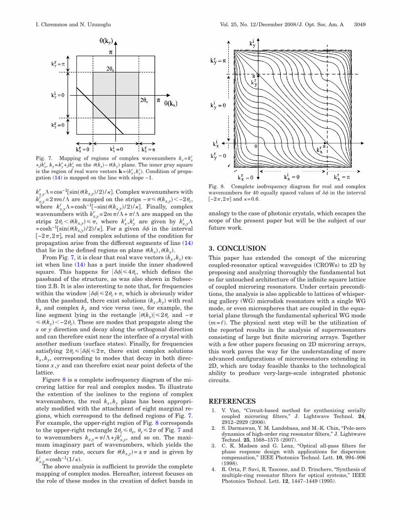
n Fig. 7, Eq. (14) becomes the equation of a line withegative slope −1 at a distance �� 2 from the origin.rom definition (13) it follows that real wavenumbers kxkx
r, ky=kyr in the interval 0,�� are respectively mapped
n the strips ���kx���2�c, ���ky���2�c (angle �c was definedn Subsection 2.B) and the inversion formulas are simply
ig. 6. (a) Mode power �b00�2 in decibels versus ky� from Eq. (15)or different values of the coupling coefficient. By reflecting theurve with respect to ky=0, we obtain the diagram for �d00�2 ver-us kx�, which is not plotted. (b) Mode power �c00�2 versus kx�,y� for �=0.6. Power �a00�2 is normalized to 0 dB.
kkwws=pt
isptwtkl�xaasktl
ctwagFttmfk
mt
asf
3Tcpsotimt�tcwta2ac
R
F+ig
Fw
I. Chremmos and N. Uzunoglu Vol. 25, No. 12 /December 2008 /J. Opt. Soc. Am. A 3049
x,yr �=cos−1sin���kx,y� /2� /��. Complex wavenumbers with
x,yr =2�m /� are mapped on the strips −����kx,y� −2�c,here kx,y
i �=cosh−1−sin���kx,y� /2� /��. Finally, complexavenumbers with kx,y
r =2m� /�+� /� are mapped on thetrips 2�c ��kx,y���, where kx
i ,kyi are given by kx,y
i �cosh−1sin���kx,y� /2� /��. For a given �� in the interval
−2� ,2��, real and complex solutions of the condition forropagation arise from the different segments of line (14)hat lie in the defined regions on plane ��kx� ,��ky�.
From Fig. 7, it is clear that real wave vectors �kx ,ky� ex-st when line (14) has a part inside the inner shadowedquare. This happens for �����4�c, which defines theassband of the structure, as was also shown in Subsec-ion 2.B. It is also interesting to note that, for frequenciesithin the window �����2�c+�, which is obviously wider
han the passband, there exist solutions �kx ,ky� with realx and complex ky and vice versa (see, for example, theine segment lying in the rectangle ���kx���2�c and −�
��ky� −2�c). These are modes that propagate along theor y direction and decay along the orthogonal direction
nd can therefore exist near the interface of a crystal withnother medium (surface states). Finally, for frequenciesatisfying 2�c� �����2�, there exist complex solutionsx ,ky, corresponding to modes that decay in both direc-ions x ,y and can therefore exist near point defects of theattice.
Figure 8 is a complete isofrequency diagram of the mi-roring lattice for real and complex modes. To illustratehe extention of the isolines to the regions of complexavenumbers, the real kx ,ky plane has been appropri-tely modified with the attachment of eight marginal re-ions, which correspond to the defined regions of Fig. 7.or example, the upper-right region of Fig. 8 correspondso the upper-right rectangle 2�c��x, �y�2� of Fig. 7 ando wavenumbers kx,y=� /�+ jkx,y
i , and so on. The maxi-um imaginary part of wavenumbers, which yields the
aster decay rate, occurs for ��kx,y�= ±� and is given by
x,yi =cosh−1�1/��.The above analysis is sufficient to provide the completeapping of complex modes. Hereafter, interest focuses on
he role of these modes in the creation of defect bands in
ig. 7. Mapping of regions of complex wavenumbers kx=kxr
jkxi , ky=ky
r + jkyi on the ��kx�−��ky� plane. The inner gray square
s the region of real wave vectors k= �kxr ,ky
r�. Condition of propa-ation (14) is mapped on the line with slope −1.
nalogy to the case of photonic crystals, which escapes thecope of the present paper but will be the subject of ouruture work.
. CONCLUSIONhis paper has extended the concept of the microringoupled-resonator optical waveguides (CROWs) to 2D byroposing and analyzing thoroughly the fundamental buto far untouched architecture of the infinite square latticef coupled microring resonators. Under certain precondi-ions, the analysis is also applicable to lattices of whisper-ng gallery (WG) microdisk resonators with a single WG
ode, or even microspheres that are coupled in the equa-orial plane through the fundamental spherical WG modem=��. The physical next step will be the utilization ofhe reported results in the analysis of superresonatorsonsisting of large but finite microring arrays. Togetherith a few other papers focusing on 2D microring arrays,
his work paves the way for the understanding of moredvanced configurations of microresonators extending inD, which are today feasible thanks to the technologicalbility to produce very-large-scale integrated photonicircuits.
EFERENCES1. V. Van, “Circuit-based method for synthesizing serially
coupled microring filters,” J. Lightwave Technol. 24,2912–2929 (2006).
2. S. Darmawan, Y. M. Landobasa, and M.-K. Chin, “Pole-zerodynamics of high-order ring resonator filters,” J. LightwaveTechnol. 25, 1568–1575 (2007).
3. C. K. Madsen and G. Lenz, “Optical all-pass filters forphase response design with applications for dispersioncompensation,” IEEE Photonics Technol. Lett. 10, 994–996(1998).
4. R. Orta, P. Savi, R. Tascone, and D. Trinchero, “Synthesis ofmultiple-ring resonator filters for optical systems,” IEEEPhotonics Technol. Lett. 12, 1447–1449 (1995).
ig. 8. Complete isofrequency diagram for real and complexavenumbers for 40 equally spaced values of �� in the interval
−2� ,2�� and �=0.6.
1
1
1
1
1
1
1
1
1
1
2
2
2
3050 J. Opt. Soc. Am. A/Vol. 25, No. 12 /December 2008 I. Chremmos and N. Uzunoglu
5. B. E. Little, S. T. Chu, H. A. Haus, J. Foresi, and J.-P.Laine, “Microring resonator channel dropping filters,” J.Lightwave Technol. 15, 998–1005 (1997).
6. B. Little, S. Chu, J. Hryniewicz, and P. Absil, “Filtersynthesis for periodically coupled microring resonators,”Opt. Lett. 25, 344–346 (2000).
7. A. Melloni, “Synthesis of a parallel-coupled ring-resonatorfilter,” Opt. Lett. 26, 917–919 (2001).
8. A. Yariv, Y. Xu, R. K. Lee, and A. Scherer, “Coupled-resonator optical waveguide: a proposal and analysis,” Opt.Lett. 24, 711–713 (1999).
9. J. Poon, J. Scheuer, Y. Xu, and A. Yariv, “Designingcoupled-resonator optical waveguide delay lines,” J. Opt.Soc. Am. B 21, 1665–1673 (2004).
0. Y. Chen and S. Blair, “Nonlinearity enhancement in finitecoupled-resonator slow-light waveguides,” Opt. Express 12,3353–3366 (2004).
1. J. Heebner, R. Boyd, and Q. Park, “Slow light, induceddispersion, enhanced nonlinearity, and optical solitons in aresonator-array waveguide,” Phys. Rev. E 65, 036619(2002).
2. D. Rafizadeh, J. P. Zhang, S. C. Hagness, A. Taflove, K. A.Stair, S. T. Ho, and R. C. Tiberio, “Waveguide-coupledAlGaAs/GaAs microcavity ring and disk resonators withhigh finesse and 21.6 nm free spectral range,” Opt. Lett.22, 1244–1246 (1997).
3. B. E. Little, J. S. Foresi, G. Steinmeyer, E. R. Thoen, S. T.Chu, H. A. Haus, E. P. Ippen, L. C. Kimerling, and W.Greene, “Ultra-compact Si–SiO2 microring resonatoroptical channel dropping filters,” IEEE Photonics Technol.
Lett. 10, 549–551 (1998).4. I. Chremmos and N. Uzunoglu, “Properties of regularpolygons of coupled microring resonators,” Appl. Opt. 46,7730–7738 (2007).
5. J. Poon, J. Scheuer, and A. Yariv, “Wavelength-selectivereflector based on a circular array of coupled microringresonators,” IEEE Photonics Technol. Lett. 16, 1331–1333(2004).
6. V. Van, “Synthesis of elliptic optical filters using mutuallycoupled microring resonators,” J. Lightwave Technol. 25,584–590 (2007).
7. I. D. Chremmos and N. K. Uzunoglu, “Propagation in adirectional coupler of parallel microring coupled-resonatoroptical waveguides,” Opt. Commun. 281, 3381–3389 (2008).
8. Y. M. Landobasa, S. Darmawan, and M.-K. Chin, “Matrixanalysis of 2-D microresonator lattice optical filters,” IEEEJ. Quantum Electron. 41, 1410–1418 (2005).
9. J. D. Joannopoulos, P. R. Villeneuve, and S. Fan, “Photoniccrystals: putting a new twist on light,” Nature 386,143–149 (1997).
0. S. Boriskina, “Spectrally engineered photonic molecules asoptical sensors with enhanced sensitivity: a proposal andnumerical analysis,” J. Opt. Soc. Am. B 23, 1565–1573(2006).
1. J. K. S. Poon, J. Scheuer, S. Mookherjea, G. T. Paloczi, Y.Huang, and A. Yariv, “Matrix analysis of microringcoupled-resonator optical waveguides,” Opt. Express 12,90–103 (2004).
2. J. D. Joannopoulos, S. G. Johnson, J. N. Winn, and R. D.Meade, Photonic Crystals: Molding the Flow of Light(Princeton University Press, 2008).