Embed Size (px)
Citation preview
Free ultra-high-Q microtoroid:
a tool for designing photonic devices Mani Hossein-Zadeh, and Kerry J. Vahala
Thomas J. Watson Laboratory of Applied Physics, California Institute of Technology, Pasadena, California 91125 USA
[email protected], www.vahala.caltech.edu
Abstract: We describe techniques that enable fabrication of a new class of photonic devices based on free UH-Q microresonators. Preliminary results show that free silica microtoroids with Qs above 30 million can be fabricated and transferred to different platforms for integration with a variety of photonic devices.
©2007 Optical Society of America
OCIS codes: (220.4000) Optical fabrication; (230.5750) Resonators.
References and links 1. B. E. Little, S. T. Chu, H. A. Haus, J. Foresi, and J.-P. Laine, “Microring resonator channel dropping
filters,” J. Lightwave Technol. 15, 998-1005 (1997). 2. B. E. Little, S. T. Chu, P. P. Absil, J. V. Hryniewicz, F. G. Johnson, F. Seiferth, D. Gill, V. Van, O. King,
and M. Trakalo, “Very high-order microring resonator filters for WDM applications,” IEEE photon. Technol. Lett. 16, 2263-2265 (2004).
3. T. Barwicz, M. A. Popovic, P. T. Ralich, M. R. Watts, H. A. Haus, E. P. Ippen, and H. I. Smith, “Microring-resonator-based add-drop filters in SiN: fabrication and analysis,” Opt. Express 12, 1437-1442 (2004).
4. M. A. Popovic, T. Barwicz, M. R. Watts, P. T. Rakich, L. Socci, E. P. Ippen, F. X. Kartner, and H. I. Smith, “ Multistage high-order microring-resonator add-drop filters,” Opt. Lett. 31, 2571-2573 (2006).
5. C. K. Madsen, G. Lenz, A. J. Bruce, M. A. Capuzzo, L. T. Gomez, T. N. Nielsen, and I. Brener, “Multistage dispersion compensator using ring resonators,” Opt. Lett. 24, 1555-1557 (1999).
6. J. K. S. Poon, L. Zhu, G. A. DeRose, and A. Yariv, “Transmission and group delay of microring coupled-resonator optical waveguides,” Opt. Lett. 31, 456-458 (2006).
7. G. Lenz and C. K. Madsen, “General optical all-pass filter structures for dispersion control in WDM systems,” J. Lightwave Technol. 17, 1248-1254 (1999).
8. T. Sadagopan, S. J. Choi, S. J. Choi, and P. D. Dapkus, A. E. Bond “Optical modulators based on depletion width translation in semiconductor microdisk resonator,” IEEE Photon. Technol. Lett. 17, 567-569 (2005).
9. P. Rabiei, W. H. Steier, C. Zhang, and L. R. Dalton, “Polymer micro-ring filters and modulators,” J. Lightwave Technol. 20, 1968-1975 (2002).
10. A. Polman, B. Min, J. Kalkman, T. J. Kippenberg and K. J. Vahala "Ultra-low-threshold erbium-implanted toroidal microlaser on silicon" Appl. Phys. Lett. 84, 1037-1039 (2004).
11. K. Djordjev, S. J. Choi, S. J. Choi, and P. D. Dapkus, “ Active semiconductor microdisk devices,” J. Lightwave Technol. 20, 105-113 (2002).
12. T. J. Kippenberg, S. M. Spillane, and K. J. Vahala, “Kerr-nonlinearity optical parametric oscillation in an ultrahigh-Q toroid microcavity” Phys. Rev. Lett. 93, 083904 (2004).
13. A. McAulay, “Nonlinear microring resonators forge all-optical switch,” Laser Focus World 41, 127-130 (2005).
14. C. Chao, and L. J. Guo, “Design and optimization of microring resonators in biochemical sensing applications,” J. Lightwave Technol. 24, 1395-1402 (2006).
15. A. M. Armani, and K. J. Vahala, "Heavy water detection using ultra-high-Q microcavities," Opt. Lett. 31, 1896-1898 (2006).
16. A. Yalcin, KC. Popat, J. C. Aldrige, T. A. Desai, J. Hryniewicz, N. Chbouki, B. E. Little, O. King, V. Van, S. Chu, D. Gill, M. Anthes-Washburn, M. S. Unlu, “ Optical sensing of biomolecules using microring resonators,” IEEE J. Sel. Top Quantum Electron. 12, 148-155 (2006).
17. B. Little, J. S. Foresi, G. Steinmeyer, E. R. Thoen, S. T. Chu, H. A. Haus, E. P. Ippen, C. L. Kimerling, W. Greene, “ Ultra-compact Si-SiO2 microring resonator optical channel dropping filters,” IEEE Photon. Technol. Lett. 10, 549-551 (1998).
18. T. Baehr-Jones, M. Hochberg, C. Walker, A. Scherer, “High-Q ring resonators in thin silicon-on-insulator,” Appl. Phys. Lett. 85, 3346-3347 (2004).
#76249 - $15.00 USD Received 19 October 2006; revised 20 December 2006; accepted 20 December 2006
(C) 2007 OSA 8 January 2007 / Vol. 15, No. 1 / OPTICS EXPRESS 166
19. D. K. Armani, T. J. Kippenberg, S. M. Spillane and K. J. Vahala, "Ultra-high-Q toroid microcavity on a chip," Nature 421, 925-929 (2003).
20. H. Rokhsari, and K. J. Vahala, “Ultralow loss, high-Q, four port resonant couplers for quantum optics and photonics,” Phys. Rev. Lett. 92, 253905 (2004)
21. T. J. Kippenberg, S. M. Spillane, and K. J. Vahala “Demonstration of ultra-high-Q small mode volume toroid microcavities on a chip” Appl. Phys. Lett. 85, 6113-6115 (2004).
22. S. M. Spillane, T. J. Kippenberg, K. J. Vahala, K. W. Goh, E. Wilcut, and H. J. Kimble, “Ultrahigh-Q toroidal microresonators for cavity quantum electrodynamics” Phys. Rev. A 71, 013817 (2005).
23. T. Aoki, B. Dayan, E. Wilcut, W. P. Bowen, A. S. Parkins, T. J. Kippenberg, K. J. Vahala, and H. J. Kimble, “Observation of strong coupling between one atom and a monolithic microresonator,” Nature 443, 671-674 (2006).
24. A. A. Savchenkov, V. S. Ilchenko, A. B. Matsko, and L. Maleki, “Higher-order filters based on chain coupled crystalline Whispering-Gallery mode resonators,” IEEE photon. Technol. Lett. 17,136-138 (2005).
25. A.A. Savchenkov, V.S. Ilchenko, A.B. Matsko and L. Maleki, “Kilohertz Optical Resonances in dielectric crystal cavities” Phys. Rev A. 70, 051804(R) (2004).
26. Nanocube piezo nanopositioning system, physikinstrumente co., Germany (www.physikinstrumente.com). 27. M. Cai, O. Painter, and Kerry J. Vahala, “Observation of critical coupling in a fiber-taper to silica-
microsphere Whispering-Gallery mode system,” Phys. Rev. Lett. 85, 74-77 (2000). 28. Microdroplets of different liquids can be generated using micropumps (for example Micro Diaphragm
Liquid Pumps from Namiki precision jewel co., Japan.) 29. T. Le, A.A. Savchenkov, H. Tazawa, W. H. Steier, and L. Maleki, “Polymer optical waveguide vertically
coupled to high-Q Whispering-Gallery resonators” IEEE Photon. Tech. Lett, 18, 859-861 (2006). 30. P. E. Barclay, K. Srinivasan, , B. Lev, H. Mabuchi, and O. Painter “Integration of fiber-coupled high-Q
SiNx microdisks with atom chips,” Appl. Phys. Lett. 89, 131108 (2006). 31. D. K. Armani, B. K. Min, A. L. Martin, and K. J. Vahala “Electrical thermo-optic tuning of ultrahigh-Q
microtoroid resonators,” Appl. Phys. Lett. 85, 5439-5441 (2004). 32. A.A. Savchenkov, V.S. Ilchenko, T. handley and L. Maleki, “Second-order filter response with series-
coupled silica microresonators” IEEE photon. Technol. Lett. 15, 543-544 (2003).
1. Introduction
Optical microring resonators (OMRs) are versatile elements for designing integrated photonic circuits, and can be used as building blocks for many optical signal processing devices and systems. It has been shown that OMRs can be employed in multipole add-drop filters [1-4], multistage dispersion compensators and delay lines [5-7], electro-optic modulators [8,9], lasers [10,11], nonlinear optical elements [12,13], and sensor applications [14-16].
Currently OMRs that are employed in most photonic devices are fabricated based on traditional monolithic techniques using various material systems such as polymers [9], III-V semiconductors [8], HydexTM [2], SiN [3], Si [17,18], etc. The quality factor of these OMRs is below 106 and is mainly limited by the surface roughness of the sidewalls that is a fundamental limitation for currently available etching techniques. Moreover the monolithic fabrication of these devices prevents post fabrication position tuning and therefore results in a device performance that is limited by the accuracy of the lithographical techniques. In the design of multipole filter and dispersion compensating elements, where the device performance is extremely sensitive to the coupling factors, post fabrication position tuning can play a crucial role in achieving the desired response (Note that some form of post fabrication tuning is currently used for final tuning of most multipole microwave and RF filters).
Ultra-high-Q (UH-Q) microtoroidal silica resonators represent a distinct class of OMRs with Qs in excess of 100 million [19]. This exceptional quality factor is a result of employing a special fabrication process that generates surface tension induced smoothness on the resonator sidewalls. This chip-based and relatively simple fabrication process allows fast production of UH-Q microtoroids with relatively high yield. Unfortunately this special process limits the range of possible integration choices for these resonators. The XeF2 dry etching and the CO2 laser reflow process can damage the microstructures and the devices built in the vicinity of the microtoroid. Also the diameter of the silica microdisk shrinks down as it reflows to its final toroidal shape. After fabrication, microtoroids are physically perched atop
#76249 - $15.00 USD Received 19 October 2006; revised 20 December 2006; accepted 20 December 2006
(C) 2007 OSA 8 January 2007 / Vol. 15, No. 1 / OPTICS EXPRESS 167
a silicon pillar so those photonic devices that rely on coupling of these resonators to an integrated waveguide or their mutual coupling cannot be realized.
At the same time, the UH-Q (low intrinsic loss) operation of microtoroid resonators makes them very attractive for applications where low loss, large circulating power, narrow-bandwidth and large dispersion are required. For example, by employing UH-Q microtoroids in multi-ring filters, bandwidths and insertion losses are possible that can outperform existing resonant optical filters. These filters would be unprecedented in optics and have immediate applications for RF photonic signal processing and DWDM optical communication systems. It has been shown that taper-coupled UH-Q microtoroids can reach exceedingly high-power transfer efficiencies in four port couplers [20]. High quality factor has a crucial role in the operation of optical ring resonator based biosensors that have been the subject of research in recent years [14-16]. It has been shown that employing silica microtoroids sensors can boost the sensitivity of the resonant optical sensors by many orders of magnitude [15]. Integration of these resonators with existing microfluidic and biophotonic devices can result in functionalities that cann’t be realized using existing monolithic microresonators.
Furthermore, the combination of their low cavity losses, small mode volume [21], and relative ease of fabrication makes microtoroid resonators promising candidates for cavity QED (cavity quantum electrodynamics) experiments [22]. Recently strong coupling between individual cesium atoms and the field of a high-Q optical mode in a microtoroid has been demonstrated [23]. Generally, there is great interest in finding ways to realize on-chip, strongly coupled systems. In addition, the ability of building a network of coupled microtoroids creates a powerful platform for realizing new cavity QED experiments.
The only substitute for silica microtoroidal cavities are UH-Q crystalline microcavities with optical Q-factors above 1010 [24,25]. These resonators are fabricated using computer controlled mechanical grinding techniques and currently they can have diameters as small as 200 μm. However, the complex fabrication technique and the fact that these resonators are usually embedded in a crystalline rod, makes their miniaturization and integration a very challenging task.
In this work we describe techniques that may enable fabrication of a new class of photonic devices based on free UH-Q microresonators. Preliminary results show that by employing simple techniques we can detach the microtoroid from the silicon pillar without any damage to the microtoroid structure and maintain their quality factor above 10 million. We have also transferred these free microtoroids from the fabrication chip to other substrates and positioned them with high accuracies. Through such feasibility tests and given the rapid growth of nanopositioning and microfabrication technologies we believe that free microtoroids can serve as new tools for designing many photonic devices in near future. Furthermore, the approach proposed here could be more universally applicable to other whispering-gallery style devices. 2. Free microtoroid fabrication
In this section we present a post-fabrication procedure that can safely release the microtoroids from the silicon pillar. Figure 1(a)-(c) shows the standard fabrication process for an UH-Q silica microtoroid [19]. First a circular silica pad (usually 2 μm thick thermally grown silica) is defined on a silicon wafer using standard photolithography and buffered HF wet etching (Fig. 1(a)). Using XeF2 isotropic dry etching a silicon pillar is formed underneath the silica microdisk. Next, the undercut silica microdisk is irradiated from top by a CO2 laser beam with a Guassian profile. Melting of the disk occurs along the periphery and forms a silica microdisk with extremely low roughness (<1nm) as a result of surface tension during the melting and solidifying process. The minor diameter of the microtoroid is defined by the magnitude of the undercut as well as the intensity of the CO2 laser beam. Usually before CO2 laser exposure the silicon pillar diameter is about 30-40% of the microdisk diameter. At this stage the silica microtoroid is strongly attached to the silicon pillar and any attempt for mechanical detachment will result in sever damage to its structure. To enable safe detachment of the silica microtoroid we reduce the diameter of the silicon pillar further (to about 2-4 μm)
#76249 - $15.00 USD Received 19 October 2006; revised 20 December 2006; accepted 20 December 2006
(C) 2007 OSA 8 January 2007 / Vol. 15, No. 1 / OPTICS EXPRESS 168
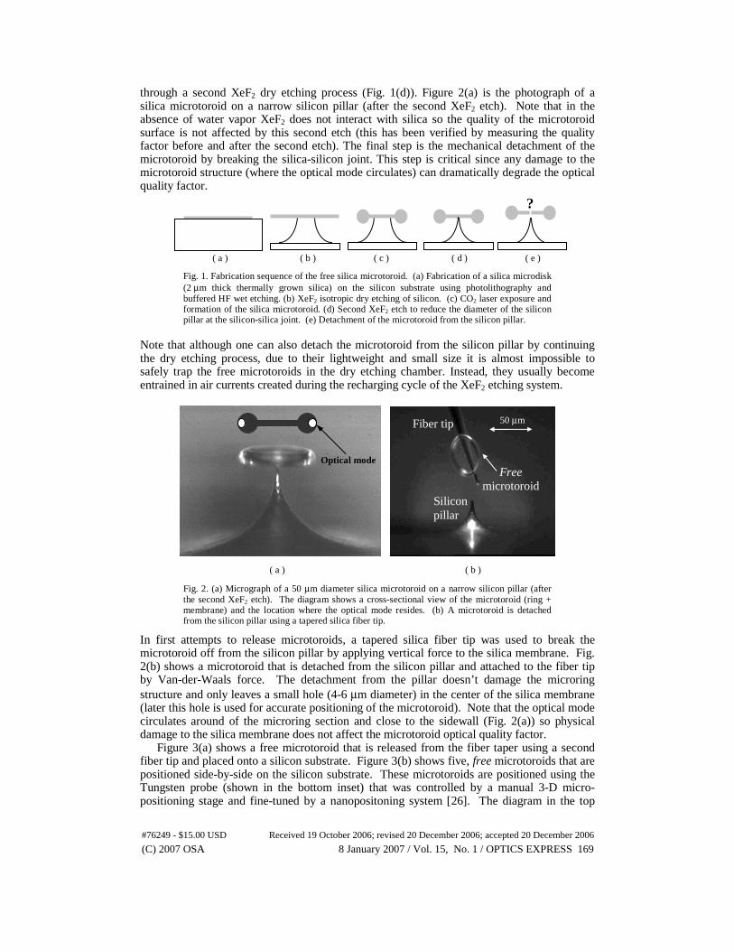
through a second XeF2 dry etching process (Fig. 1(d)). Figure 2(a) is the photograph of a silica microtoroid on a narrow silicon pillar (after the second XeF2 etch). Note that in the absence of water vapor XeF2 does not interact with silica so the quality of the microtoroid surface is not affected by this second etch (this has been verified by measuring the quality factor before and after the second etch). The final step is the mechanical detachment of the microtoroid by breaking the silica-silicon joint. This step is critical since any damage to the microtoroid structure (where the optical mode circulates) can dramatically degrade the optical quality factor.
( a ) ( b ) ( c ) ( d ) ( e )
Fig. 1. Fabrication sequence of the free silica microtoroid. (a) Fabrication of a silica microdisk (2 μm thick thermally grown silica) on the silicon substrate using photolithography and buffered HF wet etching. (b) XeF2 isotropic dry etching of silicon. (c) CO2 laser exposure and formation of the silica microtoroid. (d) Second XeF2 etch to reduce the diameter of the silicon pillar at the silicon-silica joint. (e) Detachment of the microtoroid from the silicon pillar.
Note that although one can also detach the microtoroid from the silicon pillar by continuing the dry etching process, due to their lightweight and small size it is almost impossible to safely trap the free microtoroids in the dry etching chamber. Instead, they usually become entrained in air currents created during the recharging cycle of the XeF2 etching system. ( a ) ( b )
Fig. 2. (a) Micrograph of a 50 μm diameter silica microtoroid on a narrow silicon pillar (after the second XeF2 etch). The diagram shows a cross-sectional view of the microtoroid (ring + membrane) and the location where the optical mode resides. (b) A microtoroid is detached from the silicon pillar using a tapered silica fiber tip.
In first attempts to release microtoroids, a tapered silica fiber tip was used to break the microtoroid off from the silicon pillar by applying vertical force to the silica membrane. Fig. 2(b) shows a microtoroid that is detached from the silicon pillar and attached to the fiber tip by Van-der-Waals force. The detachment from the pillar doesn’t damage the microring structure and only leaves a small hole (4-6 μm diameter) in the center of the silica membrane (later this hole is used for accurate positioning of the microtoroid). Note that the optical mode circulates around of the microring section and close to the sidewall (Fig. 2(a)) so physical damage to the silica membrane does not affect the microtoroid optical quality factor.
Figure 3(a) shows a free microtoroid that is released from the fiber taper using a second fiber tip and placed onto a silicon substrate. Figure 3(b) shows five, free microtoroids that are positioned side-by-side on the silicon substrate. These microtoroids are positioned using the Tungsten probe (shown in the bottom inset) that was controlled by a manual 3-D micro-positioning stage and fine-tuned by a nanopositoning system [26]. The diagram in the top
?
Silicon pillar
Fiber tip
Free microtoroid
Optical mode
50 μm
#76249 - $15.00 USD Received 19 October 2006; revised 20 December 2006; accepted 20 December 2006
(C) 2007 OSA 8 January 2007 / Vol. 15, No. 1 / OPTICS EXPRESS 169
inset shows how the probe (that has a footprint of 3 μm) controls the microtoroid by insertion into the central hole. ( a ) ( b )
Fig. 3. (a) A free microtoroid on the silicon substrate. (b) Five, free microtoroids detached from their pillar and lying side-by-side on the silicon wafer. The rough silicon surface is a result of XeF2 dry etching. The top inset shows how the Tungsten tip can be used to position the microtoroids. The bottom inset is a photograph of the Tungsten tip while it controls the microtoroid.
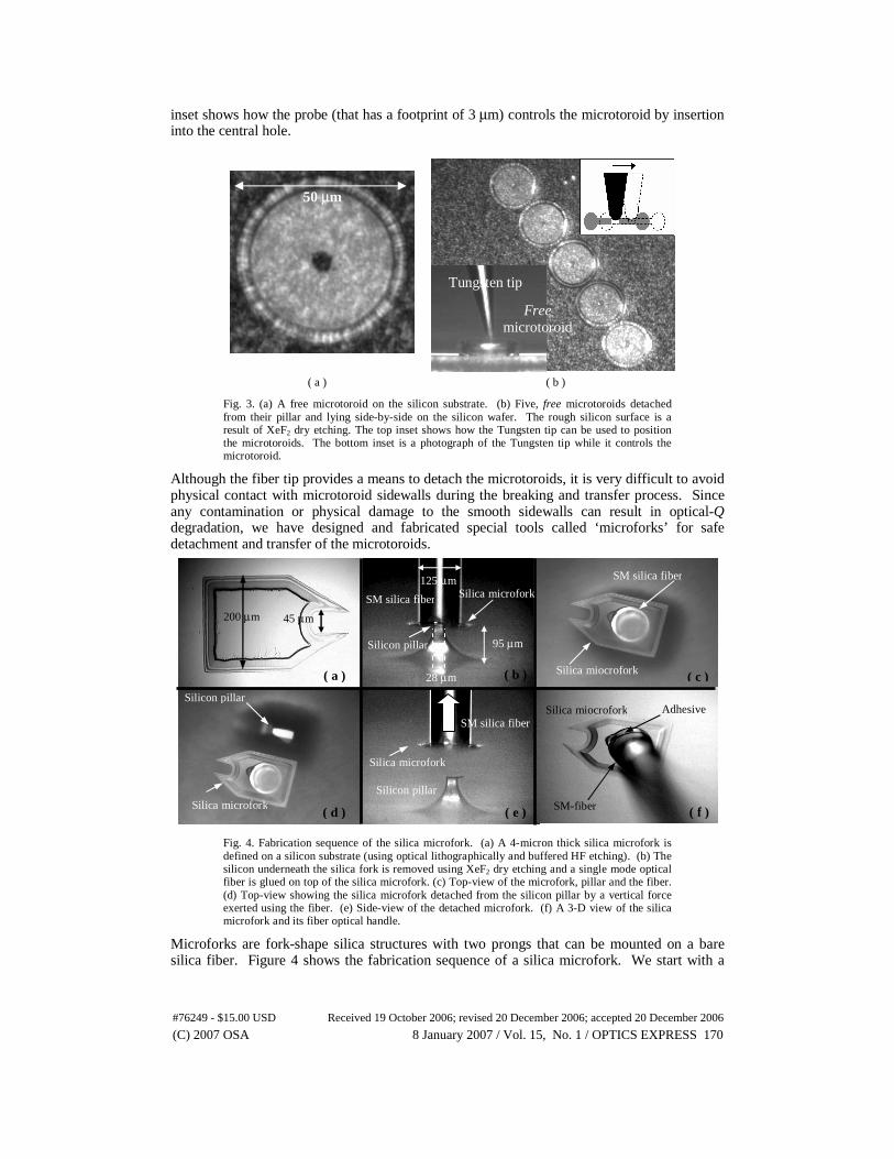
Although the fiber tip provides a means to detach the microtoroids, it is very difficult to avoid physical contact with microtoroid sidewalls during the breaking and transfer process. Since any contamination or physical damage to the smooth sidewalls can result in optical-Q degradation, we have designed and fabricated special tools called ‘microforks’ for safe detachment and transfer of the microtoroids.
Fig. 4. Fabrication sequence of the silica microfork. (a) A 4-micron thick silica microfork is defined on a silicon substrate (using optical lithographically and buffered HF etching). (b) The silicon underneath the silica fork is removed using XeF2 dry etching and a single mode optical fiber is glued on top of the silica microfork. (c) Top-view of the microfork, pillar and the fiber. (d) Top-view showing the silica microfork detached from the silicon pillar by a vertical force exerted using the fiber. (e) Side-view of the detached microfork. (f) A 3-D view of the silica microfork and its fiber optical handle.
Microforks are fork-shape silica structures with two prongs that can be mounted on a bare silica fiber. Figure 4 shows the fabrication sequence of a silica microfork. We start with a
50 μm
Free microtoroid
Tungsten tip
( b )
Silicon pillar
SM silica fiber Silica microfork 125 μm
95 μm
28 μm ( a )
( d )
Silicon pillar
SM silica fiber
( e ) ( f )
( c )
Silica microfork
SM silica fiber
Adhesive
SM-fiber
Silica miocrofork
200 μm 45 μm
Silica microfork Silicon pillar
Silica miocrofork
#76249 - $15.00 USD Received 19 October 2006; revised 20 December 2006; accepted 20 December 2006
(C) 2007 OSA 8 January 2007 / Vol. 15, No. 1 / OPTICS EXPRESS 170
silicon wafer having a 4-micron thick thermal silica layer. First the silica microfork is defined on the silicon wafer through photolithography and HF etching (Fig. 4(a)). Next, XeF2 dry etching is used to remove the silicon underneath the microfork and thereby create a relatively narrow silicon pillar. A cleaved, single-mode fiber that is coated with a small amount of adhesive is brought to the vicinity of the microfork (while the adhesive is still in liquid form). A 3-D manual micro positioning system is used to put the cleaved fiber into contact with the microfork (Fig. 4(b)(c)). After the adhesive is solidified the microfork is detached from the silicon pillar by applying a vertical force on the fiber (Fig. 4(d)(e)). The final result is a silica microfork attached to a single mode fiber that can be controlled using the micropostioning system attached to the fiber.
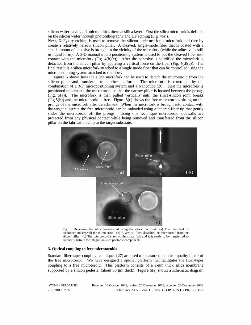
Figure 5 shows how the silica microfork can be used to detach the microtoroid from the silicon pillar and transfer it to another platform. The microfork is controlled by the combination of a 3-D micropositioning system and a Nanocube [26]. First the microfork is positioned underneath the microtoroid so that the narrow pillar is located between the prongs (Fig. 5(a)). The microfork is then pulled vertically until the silica-silicon joint breaks (Fig.5(b)) and the microtoroid is free. Figure 5(c) shows the free microtoroids sitting on the prongs of the microfork after detachment. When the microfork is brought into contact with the target substrate the free microtoroid can be unloaded using a tapered fiber tip that gently slides the microtoroid off the prongs. Using this technique microtoroid sidewalls are protected from any physical contact while being removed and transferred from the silicon pillar on the fabrication chip to the target substrate.
Fig. 5. Detaching the silica microtoroid using the silica microfork. (a) The microfork is positioned underneath the microtoroid. (b) A vertical force detaches the microtoroid from the silicon pillar. (c) The microtoroid stays on the silica fork and it is ready to be transferred to another substrate for integration with photonic components.
3. Optical coupling to free microtoroids
Standard fiber-taper coupling techniques [27] are used to measure the optical quality factor of the free microtoroid. We have designed a special platform that facilitates the fiber-taper coupling to a free microtoroid. This platform consists of a 2-μm thick silica membrane supported by a silicon pedestal (about 30 μm thick). Figure 6(a) shows a schematic diagram
( c )
( b )
Silicon pillar
( a ) Microfork
Silica fiber
Free microtoroid
Silicon pillar
#76249 - $15.00 USD Received 19 October 2006; revised 20 December 2006; accepted 20 December 2006
(C) 2007 OSA 8 January 2007 / Vol. 15, No. 1 / OPTICS EXPRESS 171
0.93
0.94
0.95
0.96
0.97
0.98
0.99
1
0 0.05 0.1 0.15 0.2 0.25 0.3
Wavelength detuning (pm)
Nor
mal
ized
tran
smitt
ed
optic
al p
ower
0.054 pm
0.93
0.94
0.95
0.96
0.97
0.98
0.99
1
0 0.05 0.1 0.15 0.2 0.25 0.3
Wavelength detuning (pm)
Nor
mal
ized
tran
smitt
ed
optic
al p
ower
0.031 pm
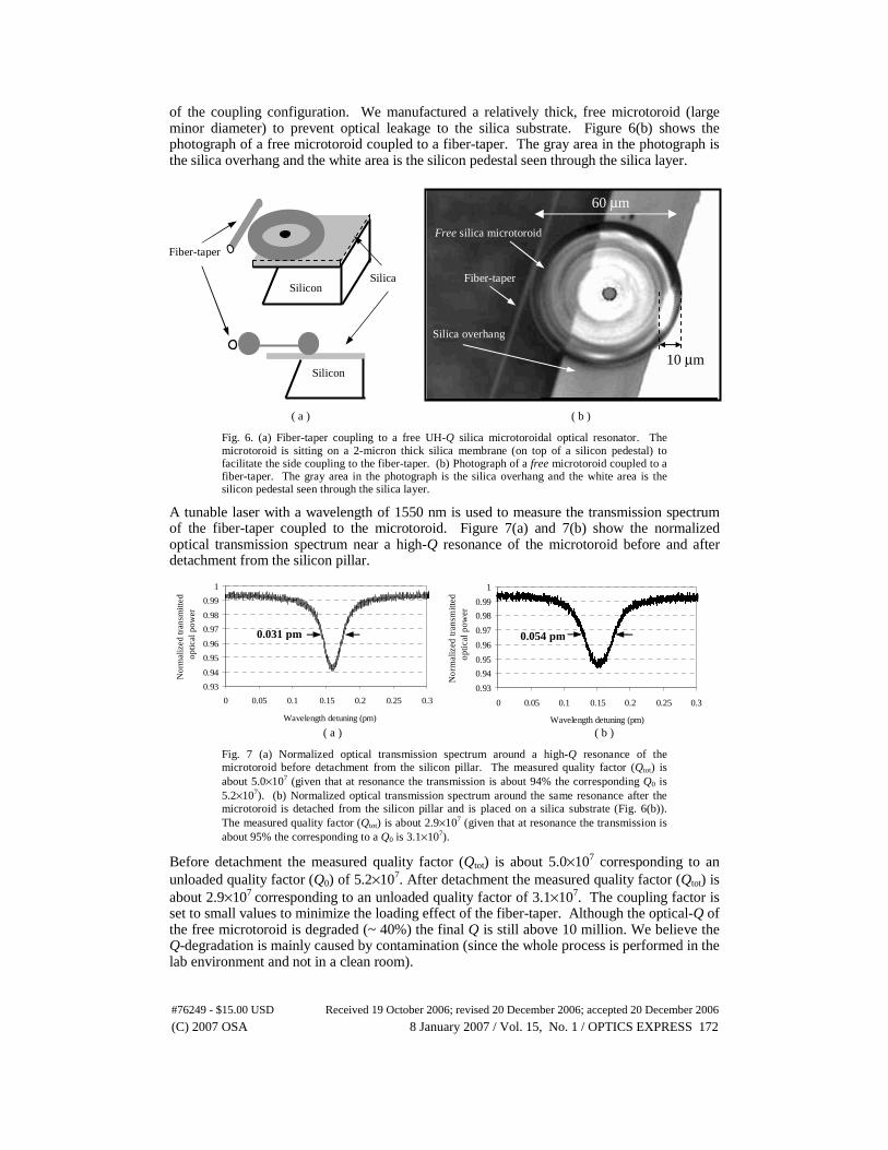
of the coupling configuration. We manufactured a relatively thick, free microtoroid (large minor diameter) to prevent optical leakage to the silica substrate. Figure 6(b) shows the photograph of a free microtoroid coupled to a fiber-taper. The gray area in the photograph is the silica overhang and the white area is the silicon pedestal seen through the silica layer. ( a ) ( b )
Fig. 6. (a) Fiber-taper coupling to a free UH-Q silica microtoroidal optical resonator. The microtoroid is sitting on a 2-micron thick silica membrane (on top of a silicon pedestal) to facilitate the side coupling to the fiber-taper. (b) Photograph of a free microtoroid coupled to a fiber-taper. The gray area in the photograph is the silica overhang and the white area is the silicon pedestal seen through the silica layer.
A tunable laser with a wavelength of 1550 nm is used to measure the transmission spectrum of the fiber-taper coupled to the microtoroid. Figure 7(a) and 7(b) show the normalized optical transmission spectrum near a high-Q resonance of the microtoroid before and after detachment from the silicon pillar.
( a ) ( b )
Fig. 7 (a) Normalized optical transmission spectrum around a high-Q resonance of the microtoroid before detachment from the silicon pillar. The measured quality factor (Qtot) is about 5.0×10⁷ (given that at resonance the transmission is about 94% the corresponding Q0 is 5.2×10⁷). (b) Normalized optical transmission spectrum around the same resonance after the microtoroid is detached from the silicon pillar and is placed on a silica substrate (Fig. 6(b)). The measured quality factor (Qtot) is about 2.9×10⁷ (given that at resonance the transmission is about 95% the corresponding to a Q0 is 3.1×10⁷).
Before detachment the measured quality factor (Qtot) is about 5.0×10⁷ corresponding to an unloaded quality factor (Q0) of 5.2×10⁷. After detachment the measured quality factor (Qtot) is about 2.9×10⁷ corresponding to an unloaded quality factor of 3.1×10⁷. The coupling factor is set to small values to minimize the loading effect of the fiber-taper. Although the optical-Q of the free microtoroid is degraded (~ 40%) the final Q is still above 10 million. We believe the Q-degradation is mainly caused by contamination (since the whole process is performed in the lab environment and not in a clean room).
60 μm
Fiber-taper
Free silica microtoroid
Silica overhang
10 μm
Fiber-taper
Silica Silicon
Silicon
#76249 - $15.00 USD Received 19 October 2006; revised 20 December 2006; accepted 20 December 2006
(C) 2007 OSA 8 January 2007 / Vol. 15, No. 1 / OPTICS EXPRESS 172
Note that due to the sidewall curvature and thickness of the microtoroid cavity the optical mode does not interact with the substrate. This is an important feature that enables the integration of these resonators on almost any substrate. Currently in majority of integrated microring resonators, the lateral optical confinement is provided by the index contrast rather than sidewall curvature consequently they must be fabricated on substrates with lower refractive index than the ring itself. This requirement sets a major limit on the variety of platforms and material systems that can be used in microring structures. 4. Future prospects
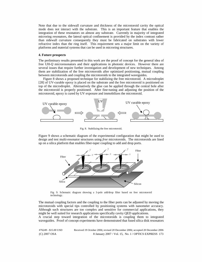
The preliminary results presented in this work are the proof of concept for the general idea of free UH-Q microresonators and their applications in photonic devices. However there are several issues that require further investigation and development of new techniques. Among them are stabilization of the free microtoroids after optimized positioning, mutual coupling between microtoroids and coupling the microtoroids to the integrated waveguides.
Figure 8 shows a proposed technique for stabilizing the free microtoroid. A microdroplet [28] of UV-curable epoxy is placed on the substrate and the free microtoroid is positioned on top of the microdroplet. Alternatively the glue can be applied through the central hole after the microtoroid is properly positioned. After fine-tuning and adjusting the position of the microtoroid, epoxy is cured by UV exposure and immobilizes the microtoroid.
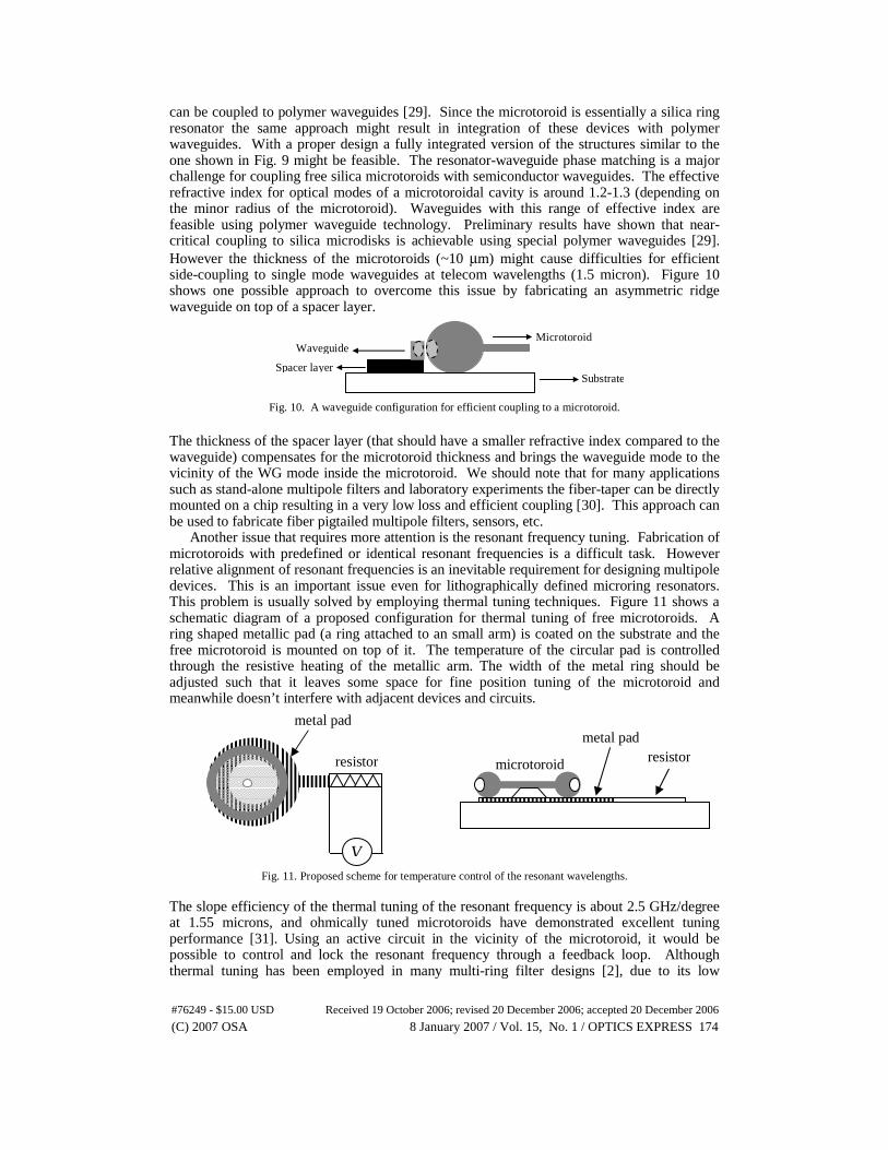
Fig. 8. Stabilizing the free microtoroid. Figure 9 shows a schematic diagram of the experimental configuration that might be used to design and test multi-resonator structures using free microtoroids. The microtoroids are lined up on a silica platform that enables fiber-taper coupling to add and drop ports.
Fig. 9. Schematic diagram showing a 3-pole add/drop filter based on free microtoroid technology.
The mutual coupling factors and the coupling to the fiber ports can be adjusted by moving the microtoroids with special tips controlled by positioning systems with nanometer accuracy. Although such structures are too complex and sensitive for commercial applications, they might be well suited for research applications specifically cavity QED applications. A crucial step toward integration of the microtoroids is coupling them to integrated waveguides. Proof of concept experiments have demonstrated that fused silica disk resonators
x
y
Fiber Taper
Fiber Taper
Silicon Silica
x
y x
y
UV curable epoxy UV UV curable epoxy
#76249 - $15.00 USD Received 19 October 2006; revised 20 December 2006; accepted 20 December 2006
(C) 2007 OSA 8 January 2007 / Vol. 15, No. 1 / OPTICS EXPRESS 173
can be coupled to polymer waveguides [29]. Since the microtoroid is essentially a silica ring resonator the same approach might result in integration of these devices with polymer waveguides. With a proper design a fully integrated version of the structures similar to the one shown in Fig. 9 might be feasible. The resonator-waveguide phase matching is a major challenge for coupling free silica microtoroids with semiconductor waveguides. The effective refractive index for optical modes of a microtoroidal cavity is around 1.2-1.3 (depending on the minor radius of the microtoroid). Waveguides with this range of effective index are feasible using polymer waveguide technology. Preliminary results have shown that near-critical coupling to silica microdisks is achievable using special polymer waveguides [29]. However the thickness of the microtoroids (~10 μm) might cause difficulties for efficient side-coupling to single mode waveguides at telecom wavelengths (1.5 micron). Figure 10 shows one possible approach to overcome this issue by fabricating an asymmetric ridge waveguide on top of a spacer layer.
Fig. 10. A waveguide configuration for efficient coupling to a microtoroid.
The thickness of the spacer layer (that should have a smaller refractive index compared to the waveguide) compensates for the microtoroid thickness and brings the waveguide mode to the vicinity of the WG mode inside the microtoroid. We should note that for many applications such as stand-alone multipole filters and laboratory experiments the fiber-taper can be directly mounted on a chip resulting in a very low loss and efficient coupling [30]. This approach can be used to fabricate fiber pigtailed multipole filters, sensors, etc.
Another issue that requires more attention is the resonant frequency tuning. Fabrication of microtoroids with predefined or identical resonant frequencies is a difficult task. However relative alignment of resonant frequencies is an inevitable requirement for designing multipole devices. This is an important issue even for lithographically defined microring resonators. This problem is usually solved by employing thermal tuning techniques. Figure 11 shows a schematic diagram of a proposed configuration for thermal tuning of free microtoroids. A ring shaped metallic pad (a ring attached to an small arm) is coated on the substrate and the free microtoroid is mounted on top of it. The temperature of the circular pad is controlled through the resistive heating of the metallic arm. The width of the metal ring should be adjusted such that it leaves some space for fine position tuning of the microtoroid and meanwhile doesn’t interfere with adjacent devices and circuits.
Fig. 11. Proposed scheme for temperature control of the resonant wavelengths. The slope efficiency of the thermal tuning of the resonant frequency is about 2.5 GHz/degree at 1.55 microns, and ohmically tuned microtoroids have demonstrated excellent tuning performance [31]. Using an active circuit in the vicinity of the microtoroid, it would be possible to control and lock the resonant frequency through a feedback loop. Although thermal tuning has been employed in many multi-ring filter designs [2], due to its low
Microtoroid
Substrate
Waveguide
Spacer layer
V
resistor metal pad
metal pad
resistor microtoroid
#76249 - $15.00 USD Received 19 October 2006; revised 20 December 2006; accepted 20 December 2006
(C) 2007 OSA 8 January 2007 / Vol. 15, No. 1 / OPTICS EXPRESS 174
accuracy and slow response time, it might not be a convenient technique for certain applications. An alternative method for tuning the frequency of silica microring resonators exploits the photosensitivity of germanate silica. The refractive index of germania-doped silica ring resonators can be tuned by controlled UV exposure. Using this technique a two-pole optical filter based on silica microring resonators has been demonstrated [32].
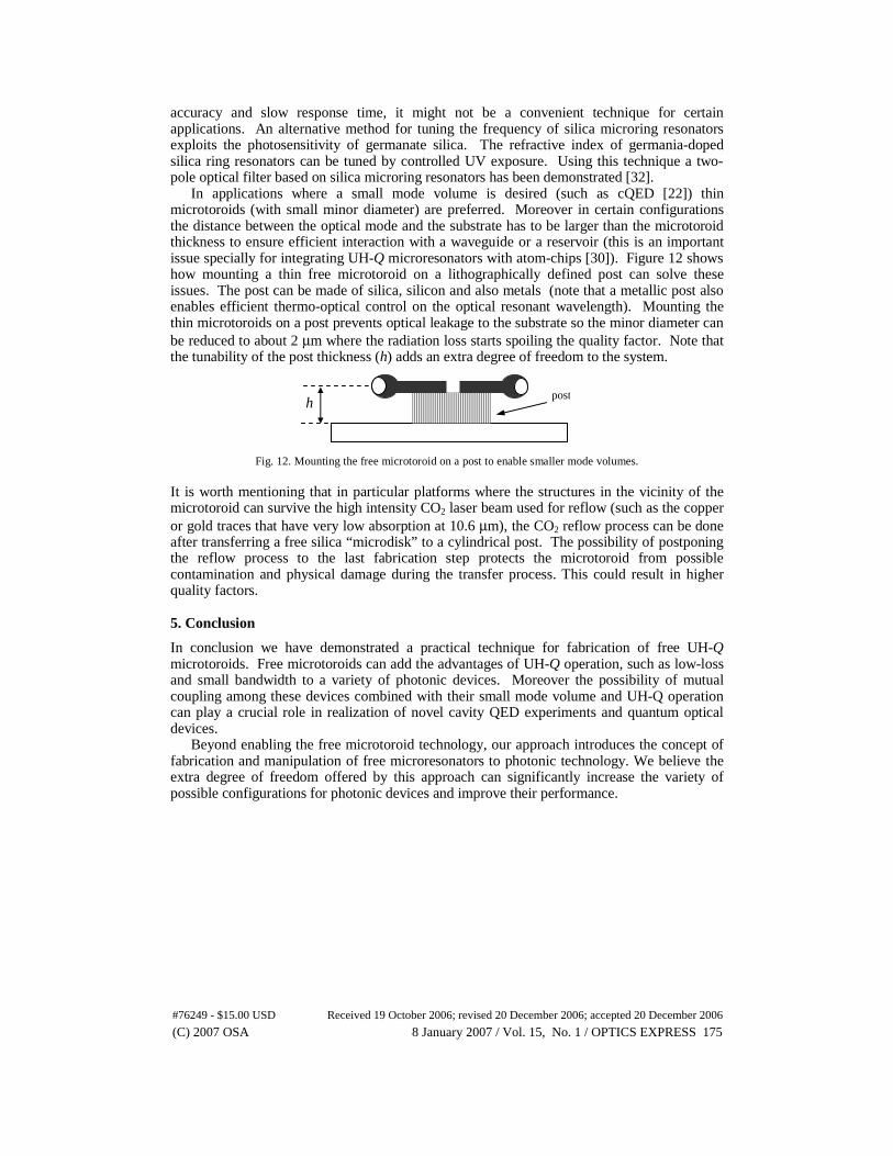
In applications where a small mode volume is desired (such as cQED [22]) thin microtoroids (with small minor diameter) are preferred. Moreover in certain configurations the distance between the optical mode and the substrate has to be larger than the microtoroid thickness to ensure efficient interaction with a waveguide or a reservoir (this is an important issue specially for integrating UH-Q microresonators with atom-chips [30]). Figure 12 shows how mounting a thin free microtoroid on a lithographically defined post can solve these issues. The post can be made of silica, silicon and also metals (note that a metallic post also enables efficient thermo-optical control on the optical resonant wavelength). Mounting the thin microtoroids on a post prevents optical leakage to the substrate so the minor diameter can be reduced to about 2 μm where the radiation loss starts spoiling the quality factor. Note that the tunability of the post thickness (h) adds an extra degree of freedom to the system.
Fig. 12. Mounting the free microtoroid on a post to enable smaller mode volumes. It is worth mentioning that in particular platforms where the structures in the vicinity of the microtoroid can survive the high intensity CO2 laser beam used for reflow (such as the copper or gold traces that have very low absorption at 10.6 μm), the CO2 reflow process can be done after transferring a free silica “microdisk” to a cylindrical post. The possibility of postponing the reflow process to the last fabrication step protects the microtoroid from possible contamination and physical damage during the transfer process. This could result in higher quality factors. 5. Conclusion
In conclusion we have demonstrated a practical technique for fabrication of free UH-Q microtoroids. Free microtoroids can add the advantages of UH-Q operation, such as low-loss and small bandwidth to a variety of photonic devices. Moreover the possibility of mutual coupling among these devices combined with their small mode volume and UH-Q operation can play a crucial role in realization of novel cavity QED experiments and quantum optical devices.
Beyond enabling the free microtoroid technology, our approach introduces the concept of fabrication and manipulation of free microresonators to photonic technology. We believe the extra degree of freedom offered by this approach can significantly increase the variety of possible configurations for photonic devices and improve their performance.
h post
#76249 - $15.00 USD Received 19 October 2006; revised 20 December 2006; accepted 20 December 2006
(C) 2007 OSA 8 January 2007 / Vol. 15, No. 1 / OPTICS EXPRESS 175