Embed Size (px)
Citation preview
Return to Session
MODERN CABLE SYSTEMS IN STEEL PIPES –
New designed XLPE-insulated cables substituting paper-insulated pipe type cables
Volker AUE, Nexans Deutschland Industries, Germany, [email protected] Wilfried ROSEBROCK, Nexans Deutschland Industries, Germany, [email protected]
ABSTRACT A lot of paper-insulated pipe-type cables are in service until now. The major part of them is still in good condition but some may also have to be replaced in the near future due to aging of the cable insulation or of the steel pipes. In many cases the steel pipes show only local defects and are suitable for further use. For these “retrofitting” Nexans has developed a new diameter-minimized three-core XLPE-insulated high voltage cable system with strongly reduced insulation thickness, that can be pulled into the existing pipes. The design of the cable and the accessories is presented in this paper. Before market introduction an extensive test program - type test and one year long term prequalification test with increased voltage and thermal load cycles adapted to IEC62067 - was performed to demonstrate the feasibility of the new cable system. The determination of the residual electrical strength of cable and accessories after the long term test does not give any indication of ageing and showed excellent results. Practical experience in the field is presented by an exemplary project in the network of a major utility in Germany for the retrofitting of 110 kV external-gas pressure cables.
KEYWORDS Three-core XLPE-insulated HV cable, reduced insulation thickness, retrofitting of pipe-type cables, long term test.
INTRODUCTION At the early beginning of installation of XLPE-insulated power cables in HV networks of 60 kV and above the electric design was quite conservative. A large thickness of polymer insulation led to a moderate electrical field strength at the conductor screen as well as in the interface to the cable accessories. Even today the majority of new installations in the 110 kV network of German utilities still maintain an insulation thickness of 18 mm as from the beginning. Excellent service experience with this cable design for about 30 years as well as extended application of XLPE-insulated cables in the higher voltage levels up to 500 kV together with improved production processes and high grade materials do however meanwhile allow a significant reduction of the insulation thickness.
As a result, the cable design gets more compact with a remarkable smaller overall diameter, which gives the possibility to lay-up 3 complete power cables of 60 kV to 110 kV voltage level in the factory. A flat steel armouring applied over the assembly at a still acceptable total diameter of the cable gives the opportunity to apply the cost and time efficient cable laying technology for 3-core high voltage cables. The main application of this cable design can be seen for the installation of new cable systems in pipes in crowded urban or industrial areas as well as the replacement of old pipe-type cable systems with impregnated paper insulation like gas pressure cables or oilostatic cables. This publication describes a new designed XLPE-cable system for retrofitting of 110 kV gas-pressure cables widely used in Germany.
1. DESIGN OF THREE-CORE XLPE-INSULATED HV CABLE Target of the development of this new cable system is a 3-core stranded XLPE-cable with an overall steel armouring for laying in pipes made of e.g. steel, concrete or plastic. Well proven construction elements of traditional pipe-type cables are used. Each individual cable has a full-size design with longitudinal and radial watertight sheath (aluminium laminated sheath) including a copper wire screen. The conductor may either be of round stranded or solid copper or aluminium. During stranding of the 3 cables the interstices are filled. An armouring of flat steel wires is applied over reinforcement tapes and fixed by a steel counter helix. This counter helix is removed before pulling the cable into pipes. Optionally fibre optic cables for online temperature monitoring or data transmission can be introduced into the interstices as well.
Return to Session
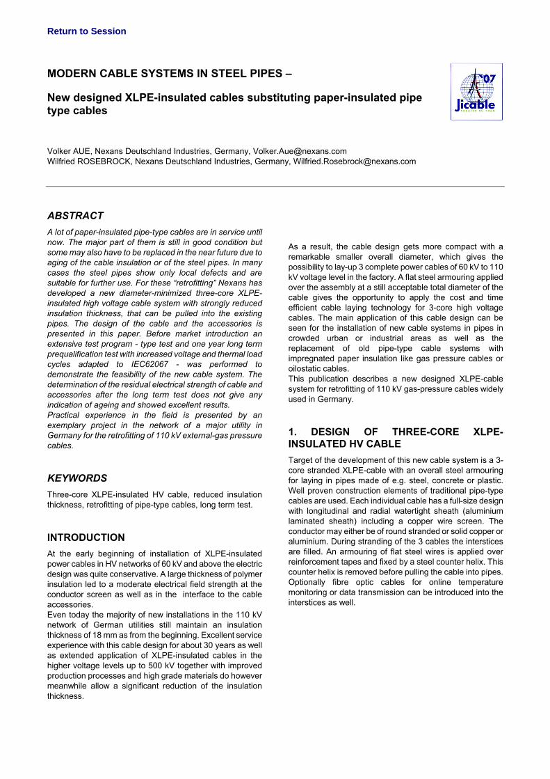
Figure 1: Pipe-type XLPE-cable 1 Conductor 7 PE-sheath 2 Conductor screen 8 Filler 3 XLPE-insulation 9 Flat steel armouring 4 Insulation screen 10 Steel pipe 5 Copper wire screen 11 PE-sheath 6 Aluminium foil 12 Fibre optic cable
1.1 Electric Dimensioning Since the beginning oil-impregnated paper-insulated HV-cables have been produced with remarkable smaller insulation thickness compared to XLPE-cables. As a result of this the overall diameter of gas-pressure cables has determined the inner diameter of the existing steel pipes. New three-core XLPE-cables for replacing paper insulated cables need to be designed to fit into the existing steel pipes without reducing the ampacity of the system, i.e. the conductor size shall be kept. The key value to limit the total diameter of the cable is obviously the thickness of the insulation and the thickness of the sheath of each individual cable.
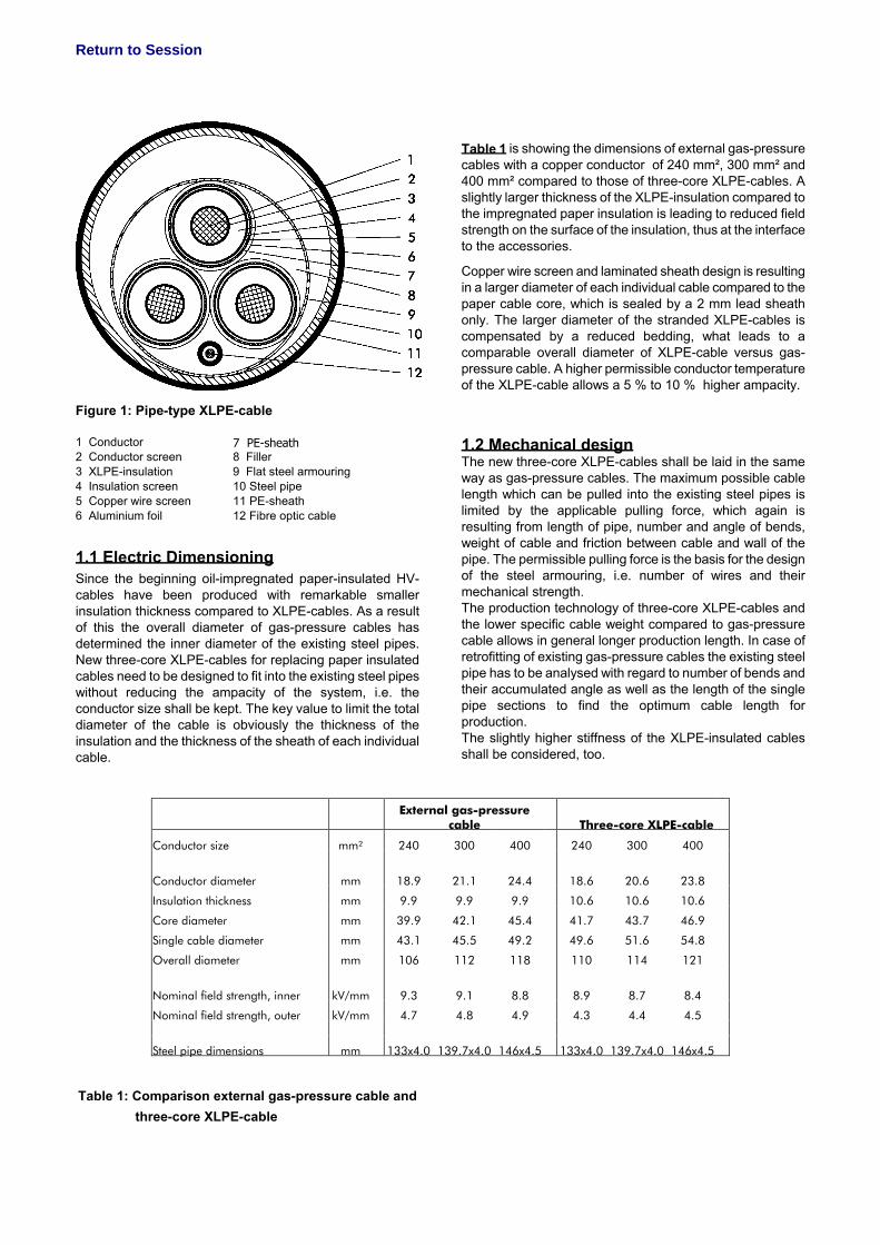
Table 1: Comparison external gas-pressure cable and three-core XLPE-cable
Table 1 is showing the dimensions of external gas-pressure cables with a copper conductor of 240 mm², 300 mm² and 400 mm² compared to those of three-core XLPE-cables. A slightly larger thickness of the XLPE-insulation compared to the impregnated paper insulation is leading to reduced field strength on the surface of the insulation, thus at the interface to the accessories.
Copper wire screen and laminated sheath design is resulting in a larger diameter of each individual cable compared to the paper cable core, which is sealed by a 2 mm lead sheath only. The larger diameter of the stranded XLPE-cables is compensated by a reduced bedding, what leads to a comparable overall diameter of XLPE-cable versus gas-pressure cable. A higher permissible conductor temperature of the XLPE-cable allows a 5 % to 10 % higher ampacity.
1.2 Mechanical design The new three-core XLPE-cables shall be laid in the same way as gas-pressure cables. The maximum possible cable length which can be pulled into the existing steel pipes is limited by the applicable pulling force, which again is resulting from length of pipe, number and angle of bends, weight of cable and friction between cable and wall of the pipe. The permissible pulling force is the basis for the design of the steel armouring, i.e. number of wires and their mechanical strength. The production technology of three-core XLPE-cables and the lower specific cable weight compared to gas-pressure cable allows in general longer production length. In case of retrofitting of existing gas-pressure cables the existing steel pipe has to be analysed with regard to number of bends and their accumulated angle as well as the length of the single pipe sections to find the optimum cable length for production. The slightly higher stiffness of the XLPE-insulated cables shall be considered, too.
External gas-pressure
cable Three-core XLPE-cable
Conductor size mm² 240 300 400 240 300 400
Conductor diameter mm 18.9 21.1 24.4 18.6 20.6 23.8
Insulation thickness mm 9.9 9.9 9.9 10.6 10.6 10.6
Core diameter mm 39.9 42.1 45.4 41.7 43.7 46.9
Single cable diameter mm 43.1 45.5 49.2 49.6 51.6 54.8
Overall diameter mm 106 112 118 110 114 121
Nominal field strength, inner kV/mm 9.3 9.1 8.8 8.9 8.7 8.4
Nominal field strength, outer kV/mm 4.7 4.8 4.9 4.3 4.4 4.5
Steel pipe dimensions mm 133x4.0 139.7x4.0 146x4.5 133x4.0 139.7x4.0 146x4.5
Return to Session
2. ACCESSORIES DESIGN Compared to XLPE-cables of standard single-core design the electrical field strength of three-core XLPE-cables with reduced insulation thickness in service is remarkably higher. This has to be considered for the design of the accessories as well as for the associated installation procedures. The typical field strength at the interface under nominal voltage is approximately 4.5 kV/mm and therefore comparable with cable systems of the 220 kV voltage level. Material and production process of prefabricated field control elements of the accessories have improved over the years, too. Today there are exclusively pre-fabricated field control elements made of polymeric material (silicone rubber, EPDM-rubber) used inside terminations and joints. Due to a 100% electrical routine test according to national and international standards (e.g. IEC 60840) at production site a most reliable quality can be reached. Accessories for this new designed XLPE-cables are basically adapted from those for XLPE-cable of standard design. The stress control elements of terminations and joints are prefabricated from EPDM. 2.1 Terminations
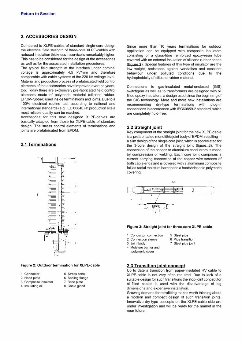
Figure 2: Outdoor termination for XLPE-cable 1 Connector 5 Stress cone 2 Head plate 6 Sealing flange 3 Composite insulator 7 Base plate 4 Insulating oil 8 Cable gland
Since more than 10 years terminations for outdoor application can be equipped with composite insulators consisting of a glass-fibre reinforced epoxy-resin tube covered with an external insulation of silicone rubber sheds (figure 2). Special features of this type of insulator are the low weight, resistance against vandalism and excellent behaviour under polluted conditions due to the hydrophobicity of silicone rubber material. Connections to gas-insulated metal-enclosed (GIS) switchgear as well as to transformers are designed with oil filled epoxy insulators, a design used since the beginning of the GIS technology. More and more new installations are recommending dry-type terminations with plug-in connections in accordance with IEC60859-2 standard, which are completely fluid-free. 2.2 Straight joint Key component of the straight joint for the new XLPE-cable is a prefabricated monolithic joint body of EPDM, resulting in a slim design of the single core joint, which is appreciated for the 3-core design of the straight joint (figure 3). The connection of the copper or aluminium conductors is made by compression or welding. Each core joint comprises a current carrying connection of the copper wire screens of both cable ends and is covered with a aluminium composite foil as radial moisture barrier and a heatshrinkable polymeric covering.
Figure 3: Straight joint for three-core XLPE-cable 1 Conductor connection 5 Steel pipe 2 Connection sleeve 6 Pipe transition 3 Joint body 7 Steel pipe joint 4 Moisture barrier and polymeric cover 2.3 Transition joint concept Up to date a transition from paper-insulated HV cable to XLPE-cable is not very often required. Due to lack of a suitable design for such transitions the stop-joint concept for oil-filled cables is used with the disadvantage of big dimensions and expensive installation. Growing demand for retrofitting makes worth thinking about a modern and compact design of such transition joints. Innovative dry-type concepts on the XLPE-cable side are under investigation and will be ready for the market in the near future.
Return to Session
3. INSTALLATION A high electric field strength at the interface between the cable and the accessories - comparable to those of cables of the 220 kV voltage level - requires special installation methods. Experience gained from investigations and a lot of installations of EHV systems 220 kV and above have led to a most reliable and well established installation procedure. Special installation tools are adapted to the small dimensions of the new three-core XLPE-cable. 3.1 Particularity of joint installation For retrofitting of gas-pressure cables, the old cables have to be pulled out of the steel pipes. Therefore the pipes have to be opened at the location of the joints. These locations along the route will later be used for the laying of the new three-core XLPE cable. One design criterion for the straight joint is the ability to use the available space after recovering of the gas-pressure joint without additional work on the pipes nor additional excavation. This space is defined by the overall length and the space available for installation. All three core joints will be covered by a steel tube joint with dimensions equivalent to a gas-pressure cable joint. Thanks to the small diameter of the core joint with its monolithic insulation body as well as to the special installation sequence these design limits can be matched. This innovative concept of the three-core XLPE-cable only needs the steel pipe during laying into the ground. As the steel pipe does not have any function during service, such as return conductor for fault currents, the trifurcation at the pipe end can be realised quite easily. A simple sealing of the trifurcation box to the outer sheath of the cables allows a slight over pressure inside the steel pipe for monitoring of the pipe integrity, if needed. Conventional trifurcating tubes between the trifurcating box and the cable terminations are not required by this concept.
4. PREQUALIFICATION AND LONG TERM TEST Prior to introduction of new cable systems into the market extensive tests are mandatory to prove feasibility and long term stability. Following tests can be outlined:
- Tests on cable: o Electric and non-electric type test o Evaluation of AC break-down voltage at
ambient temperature and at maximum permissible conductor temperature
o Evaluation of impulse breakdown voltage at ambient temperature and at maximum permissible conductor temperature
- Tests on complete system, i.e. cable and associated accessories:
o Electric type test according to national and international standards (table 2)
o AC step-test up to external flash over at the outdoor terminations
o Examination of test samples after completion of all tests
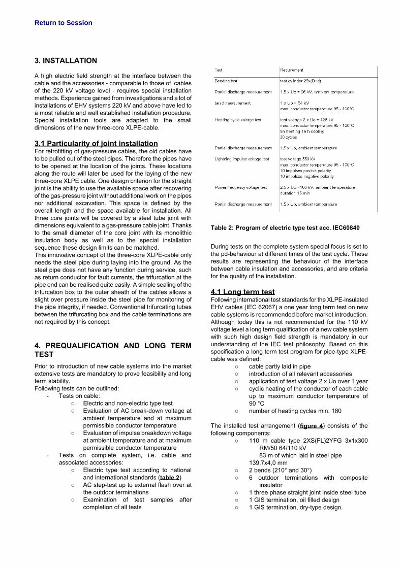
Table 2: Program of electric type test acc. IEC60840
During tests on the complete system special focus is set to the pd-behaviour at different times of the test cycle. These results are representing the behaviour of the interface between cable insulation and accessories, and are criteria for the quality of the installation. 4.1 Long term test Following international test standards for the XLPE-insulated EHV cables (IEC 62067) a one year long term test on new cable systems is recommended before market introduction. Although today this is not recommended for the 110 kV voltage level a long term qualification of a new cable system with such high design field strength is mandatory in our understanding of the IEC test philosophy. Based on this specification a long term test program for pipe-type XLPE-cable was defined:
o cable partly laid in pipe o introduction of all relevant accessories o application of test voltage 2 x Uo over 1 year o cyclic heating of the conductor of each cable
up to maximum conductor temperature of 90 °C
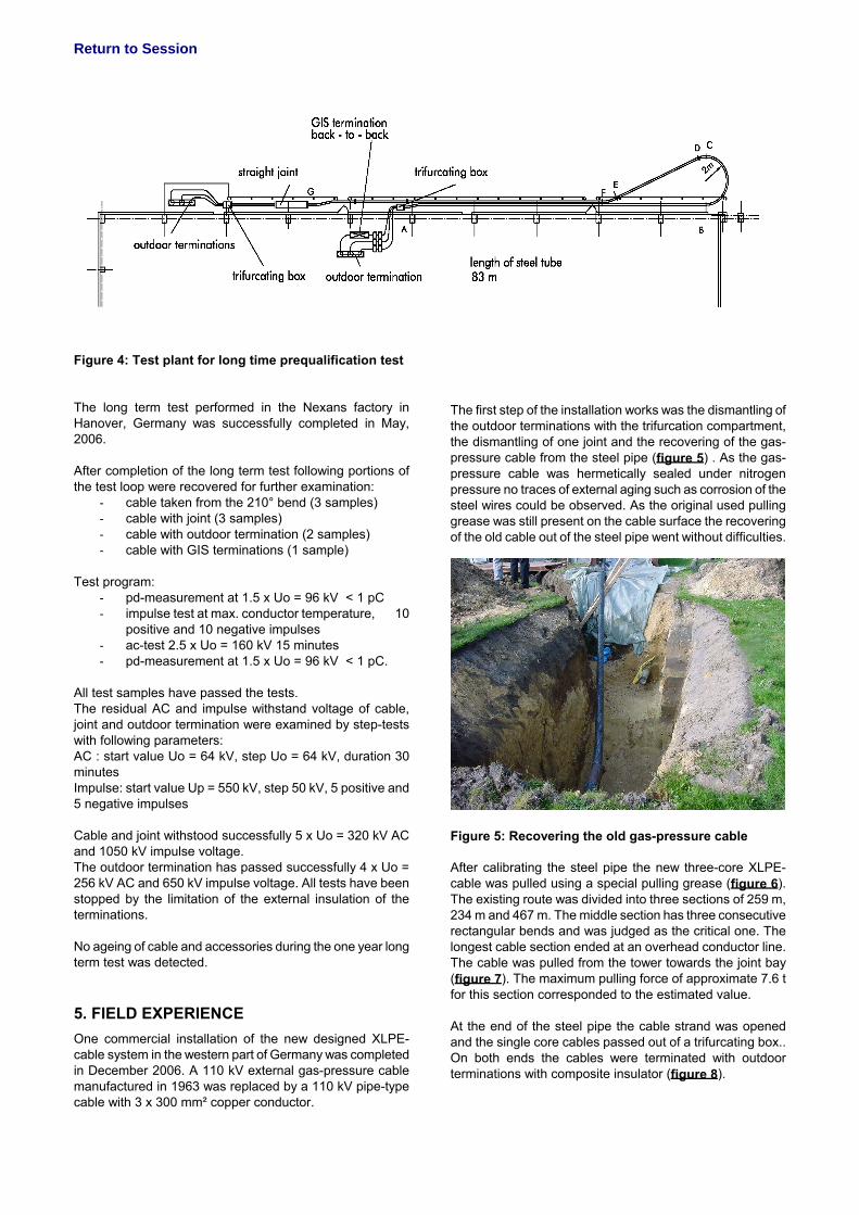
o number of heating cycles min. 180 The installed test arrangement (figure 4) consists of the following components:
o 110 m cable type 2XS(FL)2YFG 3x1x300 RM/50 64/110 kV
83 m of which laid in steel pipe 139,7x4,0 mm o 2 bends (210° and 30°) o 6 outdoor terminations with composite
insulator o 1 three phase straight joint inside steel tube o 1 GIS termination, oil filled design o 1 GIS termination, dry-type design.
Return to Session
Figure 4: Test plant for long time prequalification test The long term test performed in the Nexans factory in Hanover, Germany was successfully completed in May, 2006. After completion of the long term test following portions of the test loop were recovered for further examination:
- cable taken from the 210° bend (3 samples) - cable with joint (3 samples) - cable with outdoor termination (2 samples) - cable with GIS terminations (1 sample)
Test program:
- pd-measurement at 1.5 x Uo = 96 kV < 1 pC - impulse test at max. conductor temperature, 10
positive and 10 negative impulses - ac-test 2.5 x Uo = 160 kV 15 minutes - pd-measurement at 1.5 x Uo = 96 kV < 1 pC.
All test samples have passed the tests. The residual AC and impulse withstand voltage of cable, joint and outdoor termination were examined by step-tests with following parameters: AC : start value Uo = 64 kV, step Uo = 64 kV, duration 30 minutes Impulse: start value Up = 550 kV, step 50 kV, 5 positive and 5 negative impulses Cable and joint withstood successfully 5 x Uo = 320 kV AC and 1050 kV impulse voltage. The outdoor termination has passed successfully 4 x Uo = 256 kV AC and 650 kV impulse voltage. All tests have been stopped by the limitation of the external insulation of the terminations. No ageing of cable and accessories during the one year long term test was detected.
5. FIELD EXPERIENCE One commercial installation of the new designed XLPE-cable system in the western part of Germany was completed in December 2006. A 110 kV external gas-pressure cable manufactured in 1963 was replaced by a 110 kV pipe-type cable with 3 x 300 mm² copper conductor.
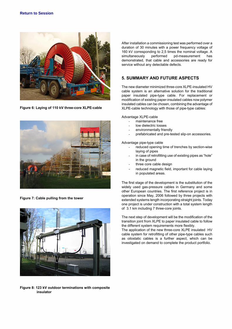
The first step of the installation works was the dismantling of the outdoor terminations with the trifurcation compartment, the dismantling of one joint and the recovering of the gas-pressure cable from the steel pipe (figure 5) . As the gas-pressure cable was hermetically sealed under nitrogen pressure no traces of external aging such as corrosion of the steel wires could be observed. As the original used pulling grease was still present on the cable surface the recovering of the old cable out of the steel pipe went without difficulties.
Figure 5: Recovering the old gas-pressure cable After calibrating the steel pipe the new three-core XLPE- cable was pulled using a special pulling grease (figure 6). The existing route was divided into three sections of 259 m, 234 m and 467 m. The middle section has three consecutive rectangular bends and was judged as the critical one. The longest cable section ended at an overhead conductor line. The cable was pulled from the tower towards the joint bay (figure 7). The maximum pulling force of approximate 7.6 t for this section corresponded to the estimated value. At the end of the steel pipe the cable strand was opened and the single core cables passed out of a trifurcating box.. On both ends the cables were terminated with outdoor terminations with composite insulator (figure 8).
Return to Session
Figure 6: Laying of 110 kV three-core XLPE-cable
Figure 7: Cable pulling from the tower
Figure 8: 123 kV outdoor terminations with composite insulator
After installation a commissioning test was performed over a duration of 30 minutes with a power frequency voltage of 160 kV corresponding to 2,5 times the nominal voltage. A simultaneously performed pd-measurement has demonstrated, that cable and accessories are ready for service without any detectable defects. 5. SUMMARY AND FUTURE ASPECTS The new diameter minimized three-core XLPE-insulated HV cable system is an alternative solution for the traditional paper insulated pipe-type cable. For replacement or modification of existing paper-insulated cables now polymer insulated cables can be chosen, combining the advantage of XLPE-cable technology with those of pipe-type cables: Advantage XLPE-cable
- maintenance free - low dielectric losses - environmentally friendly - prefabricated and pre-tested slip-on accessories.
Advantage pipe-type cable
- reduced opening time of trenches by section-wise laying of pipes
- in case of retrofitting use of existing pipes as “hole” in the ground
- three core cable design - reduced magnetic field, important for cable laying
in populated areas. The first stage of the development is the substitution of the widely used gas-pressure cables in Germany and some other European countries. The first reference project is in operation since May, 2006 followed by three projects with extended systems length incorporating straight joints. Today one project is under construction with a total system length of 3.1 km including 7 three-core joints. The next step of development will be the modification of the transition joint from XLPE to paper insulated cable to follow the different system requirements more flexibly. The application of the new three-core XLPE insulated HV cable system for retrofitting of other pipe-type cables such as oilostatic cables is a further aspect, which can be investigated on demand to complete the product portfolio.


![PVC INSULATED CABLES - Instrumentation Cables PVC Catalogue.pdf · The PVC insulated cables manufactured today by UCMB are internationally renowed for its world GPEWW UYEPMX] WXERHEVHW](https://img.pdfslide.us/doc/110x75/5a81db077f8b9aee018d983d/pvc-insulated-cables-instrumentation-pvc-cataloguepdfthe-pvc-insulated-cables.jpg)


![XLPE Insulated Cables[1]](https://img.pdfslide.us/doc/110x75/54651acaaf79596e458b492d/xlpe-insulated-cables1.jpg)