Embed Size (px)
Citation preview
ModelSim® Tutorial
Software Version 10.1a
© 1991-2012 Mentor Graphics Corporation All rights reserved.
This document contains information that is proprietary to Mentor Graphics Corporation. The original recipient of thisdocument may duplicate this document in whole or in part for internal business purposes only, provided that this entirenotice appears in all copies. In duplicating any part of this document, the recipient agrees to make every reasonableeffort to prevent the unauthorized use and distribution of the proprietary information.

This document is for information and instruction purposes. Mentor Graphics reserves the right to make changes in specifications and other information contained in this publication without prior notice, and the reader should, in all cases, consult Mentor Graphics to determine whether any changes have been made.
The terms and conditions governing the sale and licensing of Mentor Graphics products are set forth in written agreements between Mentor Graphics and its customers. No representation or other affirmation of fact contained in this publication shall be deemed to be a warranty or give rise to any liability of Mentor Graphics whatsoever.
MENTOR GRAPHICS MAKES NO WARRANTY OF ANY KIND WITH REGARD TO THIS MATERIAL INCLUDING, BUT NOT LIMITED TO, THE IMPLIED WARRANTIES OF MERCHANTABILITY AND FITNESS FOR A PARTICULAR PURPOSE.
MENTOR GRAPHICS SHALL NOT BE LIABLE FOR ANY INCIDENTAL, INDIRECT, SPECIAL, OR CONSEQUENTIAL DAMAGES WHATSOEVER (INCLUDING BUT NOT LIMITED TO LOST PROFITS) ARISING OUT OF OR RELATED TO THIS PUBLICATION OR THE INFORMATION CONTAINED IN IT, EVEN IF MENTOR GRAPHICS CORPORATION HAS BEEN ADVISED OF THE POSSIBILITY OF SUCH DAMAGES.
RESTRICTED RIGHTS LEGEND 03/97
U.S. Government Restricted Rights. The SOFTWARE and documentation have been developed entirely at private expense and are commercial computer software provided with restricted rights. Use, duplication or disclosure by the U.S. Government or a U.S. Government subcontractor is subject to the restrictions set forth in the license agreement provided with the software pursuant to DFARS 227.7202-3(a) or as set forth in subparagraph (c)(1) and (2) of the Commercial Computer Software - Restricted Rights clause at FAR 52.227-19, as applicable.
Contractor/manufacturer is:Mentor Graphics Corporation
8005 S.W. Boeckman Road, Wilsonville, Oregon 97070-7777.Telephone: 503.685.7000
Toll-Free Telephone: 800.592.2210Website: www.mentor.com
SupportNet: supportnet.mentor.com/Send Feedback on Documentation: supportnet.mentor.com/doc_feedback_form
TRADEMARKS: The trademarks, logos and service marks ("Marks") used herein are the property of Mentor Graphics Corporation or other third parties. No one is permitted to use these Marks without the prior written consent of Mentor Graphics or the respective third-party owner. The use herein of a third-party Mark is not an attempt to indicate Mentor Graphics as a source of a product, but is intended to indicate a product from, or associated with, a particular third party. A current list of Mentor Graphics’ trademarks may be viewed at: www.mentor.com/trademarks.
ModelSim Tutorial, v10.1a 3
Table of Contents
Chapter 1Introduction. . . . . . . . . . . . . . . . . . . . . . . . . . . . . . . . . . . . . . . . . . . . . . . . . . . . . . . . . . . . . . . 7
Assumptions. . . . . . . . . . . . . . . . . . . . . . . . . . . . . . . . . . . . . . . . . . . . . . . . . . . . . . . . . . . . . . 7Before you Begin . . . . . . . . . . . . . . . . . . . . . . . . . . . . . . . . . . . . . . . . . . . . . . . . . . . . . . . . . . 7
Example Designs . . . . . . . . . . . . . . . . . . . . . . . . . . . . . . . . . . . . . . . . . . . . . . . . . . . . . . . . 7
Chapter 2Conceptual Overview . . . . . . . . . . . . . . . . . . . . . . . . . . . . . . . . . . . . . . . . . . . . . . . . . . . . . . . 9
Basic Simulation Flow. . . . . . . . . . . . . . . . . . . . . . . . . . . . . . . . . . . . . . . . . . . . . . . . . . . . . . 9Project Flow. . . . . . . . . . . . . . . . . . . . . . . . . . . . . . . . . . . . . . . . . . . . . . . . . . . . . . . . . . . . . . 10Multiple Library Flow . . . . . . . . . . . . . . . . . . . . . . . . . . . . . . . . . . . . . . . . . . . . . . . . . . . . . . 11Debugging Tools . . . . . . . . . . . . . . . . . . . . . . . . . . . . . . . . . . . . . . . . . . . . . . . . . . . . . . . . . . 12
Chapter 3Basic Simulation . . . . . . . . . . . . . . . . . . . . . . . . . . . . . . . . . . . . . . . . . . . . . . . . . . . . . . . . . . . 13
Create the Working Design Library. . . . . . . . . . . . . . . . . . . . . . . . . . . . . . . . . . . . . . . . . . . . 13Compile the Design Units . . . . . . . . . . . . . . . . . . . . . . . . . . . . . . . . . . . . . . . . . . . . . . . . . . . 15Load the Design . . . . . . . . . . . . . . . . . . . . . . . . . . . . . . . . . . . . . . . . . . . . . . . . . . . . . . . . . . . 16Run the Simulation . . . . . . . . . . . . . . . . . . . . . . . . . . . . . . . . . . . . . . . . . . . . . . . . . . . . . . . . 19Set Breakpoints and Step through the Source . . . . . . . . . . . . . . . . . . . . . . . . . . . . . . . . . . . . 20
Chapter 4Projects. . . . . . . . . . . . . . . . . . . . . . . . . . . . . . . . . . . . . . . . . . . . . . . . . . . . . . . . . . . . . . . . . . . 25
Create a New Project . . . . . . . . . . . . . . . . . . . . . . . . . . . . . . . . . . . . . . . . . . . . . . . . . . . . . . . 25Add Objects to the Project . . . . . . . . . . . . . . . . . . . . . . . . . . . . . . . . . . . . . . . . . . . . . . . . . 26Changing Compile Order (VHDL) . . . . . . . . . . . . . . . . . . . . . . . . . . . . . . . . . . . . . . . . . . . 28Compile the Design. . . . . . . . . . . . . . . . . . . . . . . . . . . . . . . . . . . . . . . . . . . . . . . . . . . . . . . 29Load the Design . . . . . . . . . . . . . . . . . . . . . . . . . . . . . . . . . . . . . . . . . . . . . . . . . . . . . . . . . 30
Organizing Projects with Folders. . . . . . . . . . . . . . . . . . . . . . . . . . . . . . . . . . . . . . . . . . . . . . 31Add Folders. . . . . . . . . . . . . . . . . . . . . . . . . . . . . . . . . . . . . . . . . . . . . . . . . . . . . . . . . . . . . 31Moving Files to Folders . . . . . . . . . . . . . . . . . . . . . . . . . . . . . . . . . . . . . . . . . . . . . . . . . . . 33
Simulation Configurations . . . . . . . . . . . . . . . . . . . . . . . . . . . . . . . . . . . . . . . . . . . . . . . . . . . 33
Chapter 5Working With Multiple Libraries. . . . . . . . . . . . . . . . . . . . . . . . . . . . . . . . . . . . . . . . . . . . . 37
Creating the Resource Library . . . . . . . . . . . . . . . . . . . . . . . . . . . . . . . . . . . . . . . . . . . . . . . . 37Creating the Project . . . . . . . . . . . . . . . . . . . . . . . . . . . . . . . . . . . . . . . . . . . . . . . . . . . . . . . . 39Linking to the Resource Library . . . . . . . . . . . . . . . . . . . . . . . . . . . . . . . . . . . . . . . . . . . . . . 40
Verilog . . . . . . . . . . . . . . . . . . . . . . . . . . . . . . . . . . . . . . . . . . . . . . . . . . . . . . . . . . . . . . . . 40VHDL . . . . . . . . . . . . . . . . . . . . . . . . . . . . . . . . . . . . . . . . . . . . . . . . . . . . . . . . . . . . . . . . . 41Linking to a Resource Library . . . . . . . . . . . . . . . . . . . . . . . . . . . . . . . . . . . . . . . . . . . . . . 42
Table of Contents
4 ModelSim Tutorial, v10.1a
Permanently Mapping VHDL Resource Libraries . . . . . . . . . . . . . . . . . . . . . . . . . . . . . . . . 43
Chapter 6Analyzing Waveforms . . . . . . . . . . . . . . . . . . . . . . . . . . . . . . . . . . . . . . . . . . . . . . . . . . . . . . 45
Loading a Design . . . . . . . . . . . . . . . . . . . . . . . . . . . . . . . . . . . . . . . . . . . . . . . . . . . . . . . . . . 46Add Objects to the Wave Window . . . . . . . . . . . . . . . . . . . . . . . . . . . . . . . . . . . . . . . . . . . . 46Zooming the Waveform Display . . . . . . . . . . . . . . . . . . . . . . . . . . . . . . . . . . . . . . . . . . . . . . 47Using Cursors in the Wave Window . . . . . . . . . . . . . . . . . . . . . . . . . . . . . . . . . . . . . . . . . . . 48
Working with a Single Cursor . . . . . . . . . . . . . . . . . . . . . . . . . . . . . . . . . . . . . . . . . . . . . . 48Working with Multiple Cursors . . . . . . . . . . . . . . . . . . . . . . . . . . . . . . . . . . . . . . . . . . . . . 50
Chapter 7Viewing And Initializing Memories . . . . . . . . . . . . . . . . . . . . . . . . . . . . . . . . . . . . . . . . . . . 53
View a Memory and its Contents. . . . . . . . . . . . . . . . . . . . . . . . . . . . . . . . . . . . . . . . . . . . . . 54Navigate Within the Memory . . . . . . . . . . . . . . . . . . . . . . . . . . . . . . . . . . . . . . . . . . . . . . . 58
Export Memory Data to a File . . . . . . . . . . . . . . . . . . . . . . . . . . . . . . . . . . . . . . . . . . . . . . . . 60Initialize a Memory . . . . . . . . . . . . . . . . . . . . . . . . . . . . . . . . . . . . . . . . . . . . . . . . . . . . . . . . 61Interactive Debugging Commands . . . . . . . . . . . . . . . . . . . . . . . . . . . . . . . . . . . . . . . . . . . . 64
Chapter 8Automating Simulation . . . . . . . . . . . . . . . . . . . . . . . . . . . . . . . . . . . . . . . . . . . . . . . . . . . . . 69
Creating a Simple DO File. . . . . . . . . . . . . . . . . . . . . . . . . . . . . . . . . . . . . . . . . . . . . . . . . . . 69Running in Command-Line Mode . . . . . . . . . . . . . . . . . . . . . . . . . . . . . . . . . . . . . . . . . . . . . 70Using Tcl with the Simulator. . . . . . . . . . . . . . . . . . . . . . . . . . . . . . . . . . . . . . . . . . . . . . . . . 73
Index
End-User License Agreement
ModelSim Tutorial, v10.1a 5
List of Figures
Figure 2-1. Basic Simulation Flow - Overview Lab . . . . . . . . . . . . . . . . . . . . . . . . . . . . . . . 9Figure 2-2. Project Flow . . . . . . . . . . . . . . . . . . . . . . . . . . . . . . . . . . . . . . . . . . . . . . . . . . . . 11Figure 2-3. Multiple Library Flow. . . . . . . . . . . . . . . . . . . . . . . . . . . . . . . . . . . . . . . . . . . . . 12Figure 3-1. The Create a New Library Dialog. . . . . . . . . . . . . . . . . . . . . . . . . . . . . . . . . . . . 14Figure 3-2. work Library Added to the Library Window . . . . . . . . . . . . . . . . . . . . . . . . . . . 15Figure 3-3. Compile Source Files Dialog . . . . . . . . . . . . . . . . . . . . . . . . . . . . . . . . . . . . . . . 16Figure 3-4. Verilog Modules Compiled into work Library . . . . . . . . . . . . . . . . . . . . . . . . . . 16Figure 3-5. Loading Design with Start Simulation Dialog . . . . . . . . . . . . . . . . . . . . . . . . . . 17Figure 3-6. The Design Hierarchy . . . . . . . . . . . . . . . . . . . . . . . . . . . . . . . . . . . . . . . . . . . . . 18Figure 3-7. The Object Window and Processes Window . . . . . . . . . . . . . . . . . . . . . . . . . . . 18Figure 3-8. Using the Popup Menu to Add Signals to Wave Window . . . . . . . . . . . . . . . . . 19Figure 3-9. Waves Drawn in Wave Window. . . . . . . . . . . . . . . . . . . . . . . . . . . . . . . . . . . . . 20Figure 3-10. Setting Breakpoint in Source Window . . . . . . . . . . . . . . . . . . . . . . . . . . . . . . . 21Figure 3-11. Setting Restart Functions . . . . . . . . . . . . . . . . . . . . . . . . . . . . . . . . . . . . . . . . . 21Figure 3-12. Blue Arrow Indicates Where Simulation Stopped. . . . . . . . . . . . . . . . . . . . . . . 22Figure 3-13. Values Shown in Objects Window . . . . . . . . . . . . . . . . . . . . . . . . . . . . . . . . . . 22Figure 3-14. Parameter Name and Value in Source Examine Window . . . . . . . . . . . . . . . . 23Figure 4-1. Create Project Dialog - Project Lab . . . . . . . . . . . . . . . . . . . . . . . . . . . . . . . . . . 26Figure 4-2. Adding New Items to a Project . . . . . . . . . . . . . . . . . . . . . . . . . . . . . . . . . . . . . . 27Figure 4-3. Add file to Project Dialog . . . . . . . . . . . . . . . . . . . . . . . . . . . . . . . . . . . . . . . . . . 27Figure 4-4. Newly Added Project Files Display a ’?’ for Status . . . . . . . . . . . . . . . . . . . . . . 28Figure 4-5. Compile Order Dialog. . . . . . . . . . . . . . . . . . . . . . . . . . . . . . . . . . . . . . . . . . . . . 29Figure 4-6. Library Window with Expanded Library . . . . . . . . . . . . . . . . . . . . . . . . . . . . . . 30Figure 4-7. Structure(sim) window for a Loaded Design . . . . . . . . . . . . . . . . . . . . . . . . . . . 30Figure 4-8. Adding New Folder to Project . . . . . . . . . . . . . . . . . . . . . . . . . . . . . . . . . . . . . . 31Figure 4-9. A Folder Within a Project . . . . . . . . . . . . . . . . . . . . . . . . . . . . . . . . . . . . . . . . . . 32Figure 4-10. Creating Subfolder . . . . . . . . . . . . . . . . . . . . . . . . . . . . . . . . . . . . . . . . . . . . . . 32Figure 4-11. A folder with a Sub-folder . . . . . . . . . . . . . . . . . . . . . . . . . . . . . . . . . . . . . . . . 32Figure 4-12. Changing File Location via the Project Compiler Settings Dialog. . . . . . . . . . 33Figure 4-13. Simulation Configuration Dialog . . . . . . . . . . . . . . . . . . . . . . . . . . . . . . . . . . . 34Figure 4-14. A Simulation Configuration in the Project window . . . . . . . . . . . . . . . . . . . . . 35Figure 4-15. Transcript Shows Options for Simulation Configurations . . . . . . . . . . . . . . . . 35Figure 5-1. Creating New Resource Library . . . . . . . . . . . . . . . . . . . . . . . . . . . . . . . . . . . . . 38Figure 5-2. Compiling into the Resource Library . . . . . . . . . . . . . . . . . . . . . . . . . . . . . . . . . 39Figure 5-3. Verilog Simulation Error Reported in Transcript . . . . . . . . . . . . . . . . . . . . . . . . 41Figure 5-4. VHDL Simulation Warning Reported in Main Window . . . . . . . . . . . . . . . . . . 42Figure 5-5. Specifying a Search Library in the Simulate Dialog. . . . . . . . . . . . . . . . . . . . . . 43Figure 6-1. Panes of the Wave Window . . . . . . . . . . . . . . . . . . . . . . . . . . . . . . . . . . . . . . . . 45Figure 6-2. Zooming in with the Mouse Pointer . . . . . . . . . . . . . . . . . . . . . . . . . . . . . . . . . . 48Figure 6-3. Working with a Single Cursor in the Wave Window . . . . . . . . . . . . . . . . . . . . . 49
List of Figures
6 ModelSim Tutorial, v10.1a
Figure 6-4. Renaming a Cursor . . . . . . . . . . . . . . . . . . . . . . . . . . . . . . . . . . . . . . . . . . . . . . . 50Figure 6-5. Interval Measurement Between Two Cursors. . . . . . . . . . . . . . . . . . . . . . . . . . . 50Figure 6-6. A Locked Cursor in the Wave Window . . . . . . . . . . . . . . . . . . . . . . . . . . . . . . . 51Figure 7-1. The Memory List in the Memory window . . . . . . . . . . . . . . . . . . . . . . . . . . . . . 54Figure 7-2. Verilog Memory Data Window . . . . . . . . . . . . . . . . . . . . . . . . . . . . . . . . . . . . . 55Figure 7-3. VHDL Memory Data Window . . . . . . . . . . . . . . . . . . . . . . . . . . . . . . . . . . . . . . 55Figure 7-4. Verilog Data After Running Simulation . . . . . . . . . . . . . . . . . . . . . . . . . . . . . . . 56Figure 7-5. VHDL Data After Running Simulation . . . . . . . . . . . . . . . . . . . . . . . . . . . . . . . 56Figure 7-6. Changing the Address Radix. . . . . . . . . . . . . . . . . . . . . . . . . . . . . . . . . . . . . . . . 57Figure 7-7. New Address Radix and Line Length (Verilog. . . . . . . . . . . . . . . . . . . . . . . . . . 57Figure 7-8. New Address Radix and Line Length (VHDL) . . . . . . . . . . . . . . . . . . . . . . . . . 58Figure 7-9. Goto Dialog. . . . . . . . . . . . . . . . . . . . . . . . . . . . . . . . . . . . . . . . . . . . . . . . . . . . . 58Figure 7-10. Editing the Address Directly. . . . . . . . . . . . . . . . . . . . . . . . . . . . . . . . . . . . . . . 59Figure 7-11. Searching for a Specific Data Value . . . . . . . . . . . . . . . . . . . . . . . . . . . . . . . . . 59Figure 7-12. Export Memory Dialog . . . . . . . . . . . . . . . . . . . . . . . . . . . . . . . . . . . . . . . . . . . 60Figure 7-13. Import Memory Dialog . . . . . . . . . . . . . . . . . . . . . . . . . . . . . . . . . . . . . . . . . . . 62Figure 7-14. Initialized Memory from File and Fill Pattern . . . . . . . . . . . . . . . . . . . . . . . . . 63Figure 7-15. Data Increments Starting at Address 251 . . . . . . . . . . . . . . . . . . . . . . . . . . . . . 64Figure 7-16. Original Memory Content . . . . . . . . . . . . . . . . . . . . . . . . . . . . . . . . . . . . . . . . . 65Figure 7-17. Changing Memory Content for a Range of Addresses**OK . . . . . . . . . . . . . . 65Figure 7-18. Random Content Generated for a Range of Addresses. . . . . . . . . . . . . . . . . . . 66Figure 7-19. Changing Memory Contents by Highlighting. . . . . . . . . . . . . . . . . . . . . . . . . . 66Figure 7-20. Entering Data to Change**OK . . . . . . . . . . . . . . . . . . . . . . . . . . . . . . . . . . . . . 67Figure 7-21. Changed Memory Contents for the Specified Addresses . . . . . . . . . . . . . . . . . 67Figure 8-1. Wave Window After Running the DO File. . . . . . . . . . . . . . . . . . . . . . . . . . . . . 70Figure 8-2. The counter.wlf Dataset in the Main Window Workspace . . . . . . . . . . . . . . . . . 72
ModelSim Tutorial, v10.1a 7
Chapter 1Introduction
AssumptionsUsing this tutorial for ModelSim™ is based on the following assumptions:
• You are familiar with how to use your operating system, along with its window management system and graphical interface: OpenWindows, OSF/Motif, CDE, KDE, GNOME, or Microsoft Windows XP.
• You have a working knowledge of the language in which your design and/or test bench is written (such as VHDL, Verilog). Although ModelSim is an excellent application to use while learning HDL concepts and practices, this tutorial is not intended to support that goal.
Before you BeginPreparation for some of the lessons leaves certain details up to you. You will decide the best way to create directories, copy files, and execute programs within your operating system. (When you are operating the simulator within ModelSim’s GUI, the interface is consistent for all platforms.)
Examples show Windows path separators - use separators appropriate for your operating system when trying the examples.
Example DesignsModelSim comes with Verilog and VHDL versions of the designs used in these lessons. This allows you to do the tutorial regardless of which license type you have. Though we have tried to minimize the differences between the Verilog and VHDL versions, we could not do so in all cases. In cases where the designs differ (e.g., line numbers or syntax), you will find language-specific instructions. Follow the instructions that are appropriate for the language you use.

ModelSim Tutorial, v10.1a8
IntroductionBefore you Begin
ModelSim Tutorial, v10.1a 9
Chapter 2Conceptual Overview
Introduction
ModelSim is a verification and simulation tool for VHDL, Verilog, SystemVerilog, and mixed-language designs.
This lesson provides a brief conceptual overview of the ModelSim simulation environment. It is divided into fourtopics, which you will learn more about in subsequent lessons.
• Basic simulation flow — Refer to Chapter 3, Basic Simulation.
• Project flow — Refer to Chapter 4, Projects.
• Multiple library flow — Refer to Chapter 5, Working With Multiple Libraries.
• Debugging tools — Refer to remaining lessons.
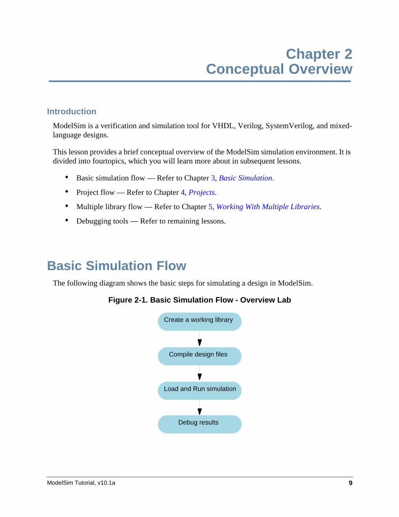
Basic Simulation FlowThe following diagram shows the basic steps for simulating a design in ModelSim.
Figure 2-1. Basic Simulation Flow - Overview Lab
Create a working library
Compile design files
Load and Run simulation
Debug results
ModelSim Tutorial, v10.1a10
Conceptual OverviewProject Flow
• Creating the Working Library
In ModelSim, all designs are compiled into a library. You typically start a new simulation in ModelSim by creating a working library called "work," which is the default library name used by the compiler as the default destination for compiled design units.
• Compiling Your Design
After creating the working library, you compile your design units into it. The ModelSim library format is compatible across all supported platforms. You can simulate your design on any platform without having to recompile your design.
• Loading the Simulator with Your Design and Running the Simulation
With the design compiled, you load the simulator with your design by invoking the simulator on a top-level module (Verilog) or a configuration or entity/architecture pair (VHDL).
Assuming the design loads successfully, the simulation time is set to zero, and you enter a run command to begin simulation.
• Debugging Your Results
If you don’t get the results you expect, you can use ModelSim’s robust debugging environment to track down the cause of the problem.
Project FlowA project is a collection mechanism for an HDL design under specification or test. Even though you don’t have to use projects in ModelSim, they may ease interaction with the tool and are useful for organizing files and specifying simulation settings.
The following diagram shows the basic steps for simulating a design within a ModelSim project.
Conceptual OverviewMultiple Library Flow
ModelSim Tutorial, v10.1a 11
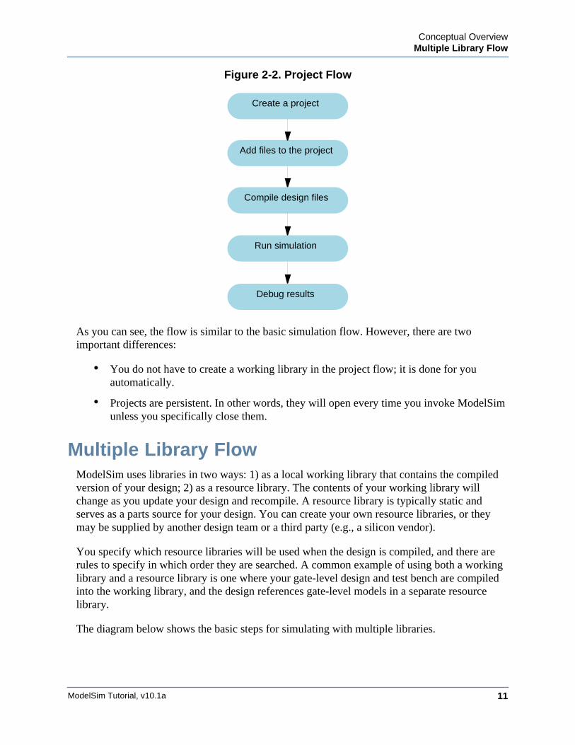
Figure 2-2. Project Flow
As you can see, the flow is similar to the basic simulation flow. However, there are two important differences:
• You do not have to create a working library in the project flow; it is done for you automatically.
• Projects are persistent. In other words, they will open every time you invoke ModelSim unless you specifically close them.
Multiple Library FlowModelSim uses libraries in two ways: 1) as a local working library that contains the compiled version of your design; 2) as a resource library. The contents of your working library will change as you update your design and recompile. A resource library is typically static and serves as a parts source for your design. You can create your own resource libraries, or they may be supplied by another design team or a third party (e.g., a silicon vendor).
You specify which resource libraries will be used when the design is compiled, and there are rules to specify in which order they are searched. A common example of using both a working library and a resource library is one where your gate-level design and test bench are compiled into the working library, and the design references gate-level models in a separate resource library.
The diagram below shows the basic steps for simulating with multiple libraries.
Create a project
Add files to the project
Run simulation
Debug results
Compile design files
ModelSim Tutorial, v10.1a12
Conceptual OverviewDebugging Tools
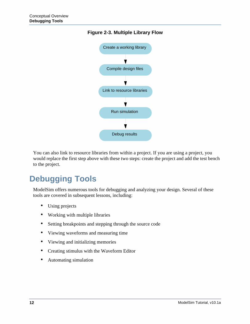
Figure 2-3. Multiple Library Flow
You can also link to resource libraries from within a project. If you are using a project, you would replace the first step above with these two steps: create the project and add the test bench to the project.
Debugging ToolsModelSim offers numerous tools for debugging and analyzing your design. Several of these tools are covered in subsequent lessons, including:
• Using projects
• Working with multiple libraries
• Setting breakpoints and stepping through the source code
• Viewing waveforms and measuring time
• Viewing and initializing memories
• Creating stimulus with the Waveform Editor
• Automating simulation
Create a working library
Compile design files
Run simulation
Debug results
Link to resource libraries
ModelSim Tutorial, v10.1a 13
Chapter 3Basic Simulation
Introduction
In this lesson you will go step-by-step through the basic simulation flow:
1. Create the Working Design Library
2. Compile the Design Units
3. Load the Design
4. Run the Simulation
Design Files for this Lesson
The sample design for this lesson is a simple 8-bit, binary up-counter with an associated test bench. The pathnames are as follows:
Verilog – <install_dir>/examples/tutorials/verilog/basicSimulation/counter.v and tcounter.v
VHDL – <install_dir>/examples/tutorials/vhdl/basicSimulation/counter.vhd and tcounter.vhd
This lesson uses the Verilog files counter.v and tcounter.v. If you have a VHDL license, use counter.vhd and tcounter.vhd instead. Or, if you have a mixed license, feel free to use the Verilog test bench with the VHDL counter or vice versa.
Related Reading
User’s Manual Chapters: Design Libraries, Verilog and SystemVerilog Simulation, and VHDL Simulation.
Reference Manual commands: vlib, vmap, vlog, vcom, view, and run.
Create the Working Design LibraryBefore you can simulate a design, you must first create a library and compile the source code into that library.
1. Create a new directory and copy the design files for this lesson into it.
Start by creating a new directory for this exercise (in case other users will be working with these lessons).
ModelSim Tutorial, v10.1a14
Basic SimulationCreate the Working Design Library
Verilog: Copy counter.v and tcounter.v files from /<install_dir>/examples/tutorials/verilog/basicSimulation to the new directory.
VHDL: Copy counter.vhd and tcounter.vhd files from /<install_dir>/examples/tutorials/vhdl/basicSimulation to the new directory.
2. Start ModelSim if necessary.
a. Type vsim at a UNIX shell prompt or use the ModelSim icon in Windows.
Upon opening ModelSim for the first time, you will see the Welcome to ModelSim dialog. Click Close.
b. Select File > Change Directory and change to the directory you created in step 1.
3. Create the working library.
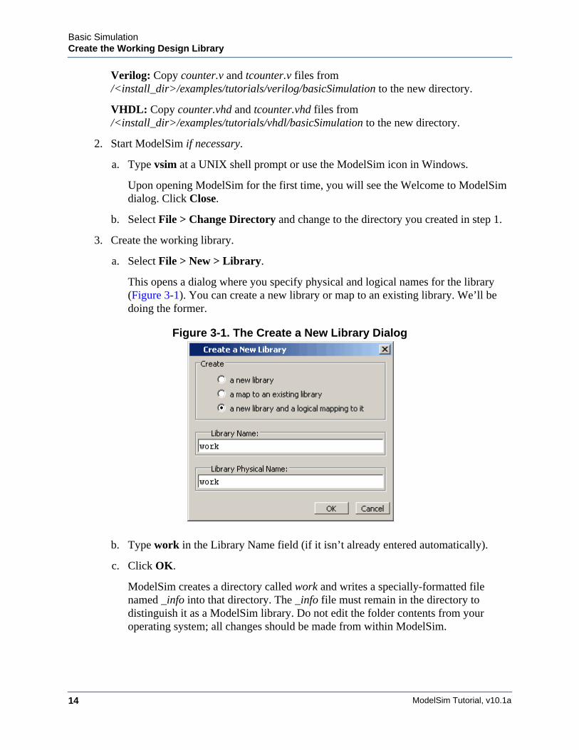
a. Select File > New > Library.
This opens a dialog where you specify physical and logical names for the library (Figure 3-1). You can create a new library or map to an existing library. We’ll be doing the former.
Figure 3-1. The Create a New Library Dialog
b. Type work in the Library Name field (if it isn’t already entered automatically).
c. Click OK.
ModelSim creates a directory called work and writes a specially-formatted file named _info into that directory. The _info file must remain in the directory to distinguish it as a ModelSim library. Do not edit the folder contents from your operating system; all changes should be made from within ModelSim.
Basic SimulationCompile the Design Units
ModelSim Tutorial, v10.1a 15
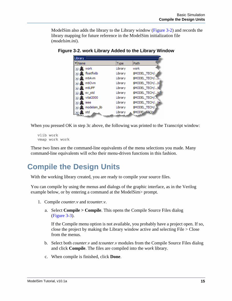
ModelSim also adds the library to the Library window (Figure 3-2) and records the library mapping for future reference in the ModelSim initialization file (modelsim.ini).
Figure 3-2. work Library Added to the Library Window
When you pressed OK in step 3c above, the following was printed to the Transcript window:
vlib workvmap work work
These two lines are the command-line equivalents of the menu selections you made. Many command-line equivalents will echo their menu-driven functions in this fashion.
Compile the Design UnitsWith the working library created, you are ready to compile your source files.
You can compile by using the menus and dialogs of the graphic interface, as in the Verilog example below, or by entering a command at the ModelSim> prompt.
1. Compile counter.v and tcounter.v.
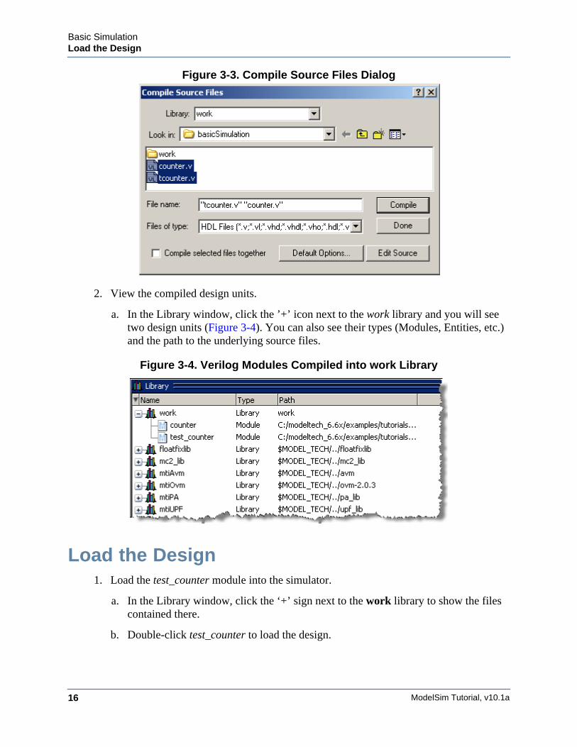
a. Select Compile > Compile. This opens the Compile Source Files dialog (Figure 3-3).
If the Compile menu option is not available, you probably have a project open. If so, close the project by making the Library window active and selecting File > Close from the menus.
b. Select both counter.v and tcounter.v modules from the Compile Source Files dialog and click Compile. The files are compiled into the work library.
c. When compile is finished, click Done.
ModelSim Tutorial, v10.1a16
Basic SimulationLoad the Design
Figure 3-3. Compile Source Files Dialog
2. View the compiled design units.
a. In the Library window, click the ’+’ icon next to the work library and you will see two design units (Figure 3-4). You can also see their types (Modules, Entities, etc.) and the path to the underlying source files.
Figure 3-4. Verilog Modules Compiled into work Library
Load the Design1. Load the test_counter module into the simulator.
a. In the Library window, click the ‘+’ sign next to the work library to show the files contained there.
b. Double-click test_counter to load the design.
Basic SimulationLoad the Design
ModelSim Tutorial, v10.1a 17
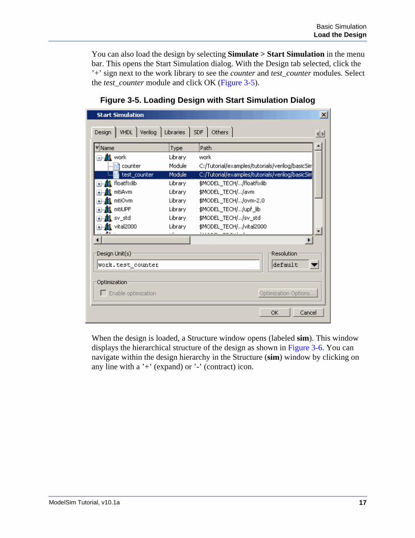
You can also load the design by selecting Simulate > Start Simulation in the menu bar. This opens the Start Simulation dialog. With the Design tab selected, click the ’+’ sign next to the work library to see the counter and test_counter modules. Select the test_counter module and click OK (Figure 3-5).
Figure 3-5. Loading Design with Start Simulation Dialog
When the design is loaded, a Structure window opens (labeled sim). This window displays the hierarchical structure of the design as shown in Figure 3-6. You can navigate within the design hierarchy in the Structure (sim) window by clicking on any line with a ’+’ (expand) or ’-’ (contract) icon.
ModelSim Tutorial, v10.1a18
Basic SimulationLoad the Design
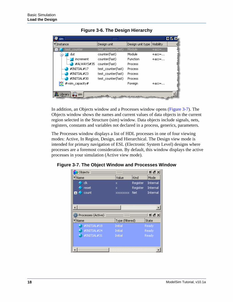
Figure 3-6. The Design Hierarchy
In addition, an Objects window and a Processes window opens (Figure 3-7). The Objects window shows the names and current values of data objects in the current region selected in the Structure (sim) window. Data objects include signals, nets, registers, constants and variables not declared in a process, generics, parameters.
The Processes window displays a list of HDL processes in one of four viewing modes: Active, In Region, Design, and Hierarchical. The Design view mode is intended for primary navigation of ESL (Electronic System Level) designs where processes are a foremost consideration. By default, this window displays the active processes in your simulation (Active view mode).
Figure 3-7. The Object Window and Processes Window
Basic SimulationRun the Simulation
ModelSim Tutorial, v10.1a 19
Run the SimulationWe’re ready to run the simulation. But before we do, we’ll open the Wave window and add signals to it.
1. Open the Wave window.
a. Enter view wave at the command line.
The Wave window opens in the right side of the Main window. Resize it so it is visible.
You can also use the View > Wave menu selection to open a Wave window. The Wave window is just one of several debugging windows available on the View menu.
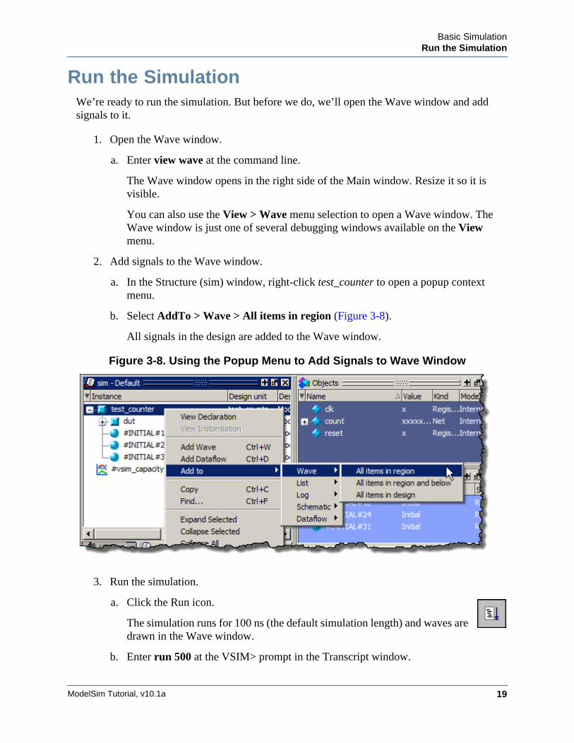
2. Add signals to the Wave window.
a. In the Structure (sim) window, right-click test_counter to open a popup context menu.
b. Select AddTo > Wave > All items in region (Figure 3-8).
All signals in the design are added to the Wave window.
Figure 3-8. Using the Popup Menu to Add Signals to Wave Window
3. Run the simulation.
a. Click the Run icon.
The simulation runs for 100 ns (the default simulation length) and waves are drawn in the Wave window.
b. Enter run 500 at the VSIM> prompt in the Transcript window.
ModelSim Tutorial, v10.1a20
Basic SimulationSet Breakpoints and Step through the Source
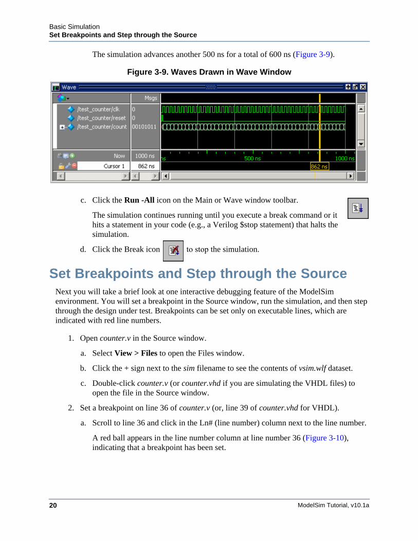
The simulation advances another 500 ns for a total of 600 ns (Figure 3-9).
Figure 3-9. Waves Drawn in Wave Window
c. Click the Run -All icon on the Main or Wave window toolbar.
The simulation continues running until you execute a break command or it hits a statement in your code (e.g., a Verilog $stop statement) that halts the simulation.
d. Click the Break icon to stop the simulation.
Set Breakpoints and Step through the SourceNext you will take a brief look at one interactive debugging feature of the ModelSim environment. You will set a breakpoint in the Source window, run the simulation, and then step through the design under test. Breakpoints can be set only on executable lines, which are indicated with red line numbers.
1. Open counter.v in the Source window.
a. Select View > Files to open the Files window.
b. Click the + sign next to the sim filename to see the contents of vsim.wlf dataset.
c. Double-click counter.v (or counter.vhd if you are simulating the VHDL files) to open the file in the Source window.
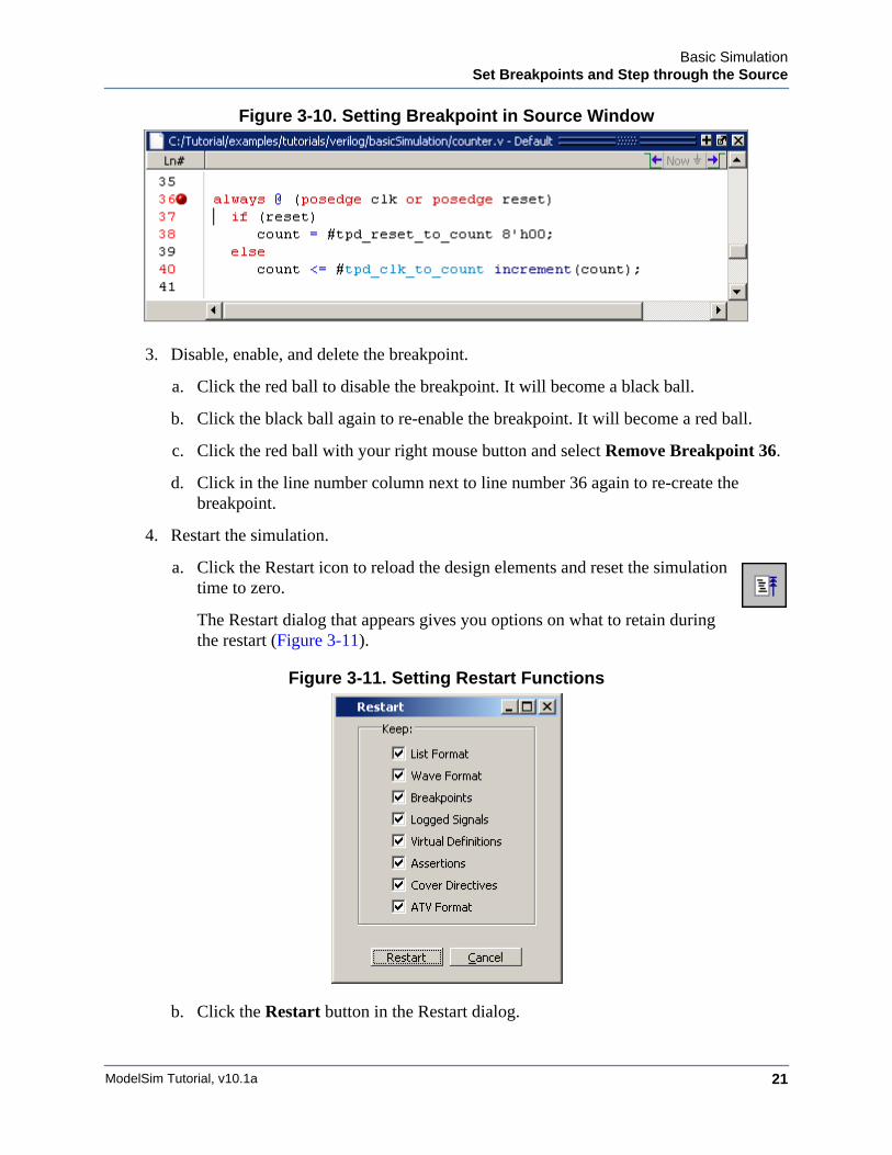
2. Set a breakpoint on line 36 of counter.v (or, line 39 of counter.vhd for VHDL).
a. Scroll to line 36 and click in the Ln# (line number) column next to the line number.
A red ball appears in the line number column at line number 36 (Figure 3-10), indicating that a breakpoint has been set.
Basic SimulationSet Breakpoints and Step through the Source
ModelSim Tutorial, v10.1a 21
Figure 3-10. Setting Breakpoint in Source Window
3. Disable, enable, and delete the breakpoint.
a. Click the red ball to disable the breakpoint. It will become a black ball.
b. Click the black ball again to re-enable the breakpoint. It will become a red ball.
c. Click the red ball with your right mouse button and select Remove Breakpoint 36.
d. Click in the line number column next to line number 36 again to re-create the breakpoint.
4. Restart the simulation.
a. Click the Restart icon to reload the design elements and reset the simulation time to zero.
The Restart dialog that appears gives you options on what to retain during the restart (Figure 3-11).
Figure 3-11. Setting Restart Functions
b. Click the Restart button in the Restart dialog.
ModelSim Tutorial, v10.1a22
Basic SimulationSet Breakpoints and Step through the Source
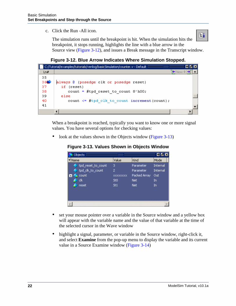
c. Click the Run -All icon.
The simulation runs until the breakpoint is hit. When the simulation hits the breakpoint, it stops running, highlights the line with a blue arrow in the Source view (Figure 3-12), and issues a Break message in the Transcript window.
Figure 3-12. Blue Arrow Indicates Where Simulation Stopped.
When a breakpoint is reached, typically you want to know one or more signal values. You have several options for checking values:
• look at the values shown in the Objects window (Figure 3-13)
Figure 3-13. Values Shown in Objects Window
• set your mouse pointer over a variable in the Source window and a yellow box will appear with the variable name and the value of that variable at the time of the selected cursor in the Wave window
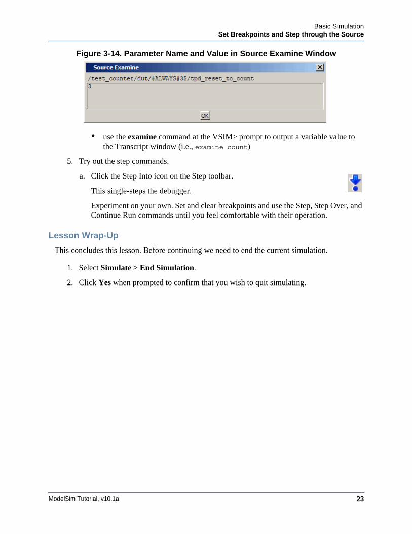
• highlight a signal, parameter, or variable in the Source window, right-click it, and select Examine from the pop-up menu to display the variable and its current value in a Source Examine window (Figure 3-14)
Basic SimulationSet Breakpoints and Step through the Source
ModelSim Tutorial, v10.1a 23
Figure 3-14. Parameter Name and Value in Source Examine Window
• use the examine command at the VSIM> prompt to output a variable value to the Transcript window (i.e., examine count)
5. Try out the step commands.
a. Click the Step Into icon on the Step toolbar.
This single-steps the debugger.
Experiment on your own. Set and clear breakpoints and use the Step, Step Over, and Continue Run commands until you feel comfortable with their operation.
Lesson Wrap-Up
This concludes this lesson. Before continuing we need to end the current simulation.
1. Select Simulate > End Simulation.
2. Click Yes when prompted to confirm that you wish to quit simulating.

ModelSim Tutorial, v10.1a24
Basic SimulationSet Breakpoints and Step through the Source
ModelSim Tutorial, v10.1a 25
Chapter 4Projects
Introduction
In this lesson you will practice creating a project.
At a minimum, projects contain a work library and a session state that is stored in an .mpf file. A project may also consist of:
• HDL source files or references to source files
• other files such as READMEs or other project documentation
• local libraries
• references to global libraries
Design Files for this Lesson
The sample design for this lesson is a simple 8-bit, binary up-counter with an associated test bench. The pathnames are as follows:
Verilog – <install_dir>/examples/tutorials/verilog/projects/counter.v and tcounter.v
VHDL – <install_dir>/examples/tutorials/vhdl/projects/counter.vhd and tcounter.vhd
This lesson uses the Verilog files tcounter.v and counter.v. If you have a VHDL license, use tcounter.vhd and counter.vhd instead.
Related Reading
User’s Manual Chapter: Projects.
Create a New Project1. Create a new directory and copy the design files for this lesson into it.
Start by creating a new directory for this exercise (in case other users will be working with these lessons).
Verilog: Copy counter.v and tcounter.v files from /<install_dir>/examples/tutorials/verilog/projects to the new directory.
VHDL: Copy counter.vhd and tcounter.vhd files from /<install_dir>/examples/tutorials/vhdl/projects to the new directory.
ModelSim Tutorial, v10.1a26
ProjectsCreate a New Project
2. If you just finished the previous lesson, ModelSim should already be running. If not, start ModelSim.
a. Type vsim at a UNIX shell prompt or use the ModelSim icon in Windows.
b. Select File > Change Directory and change to the directory you created in step 1.
3. Create a new project.
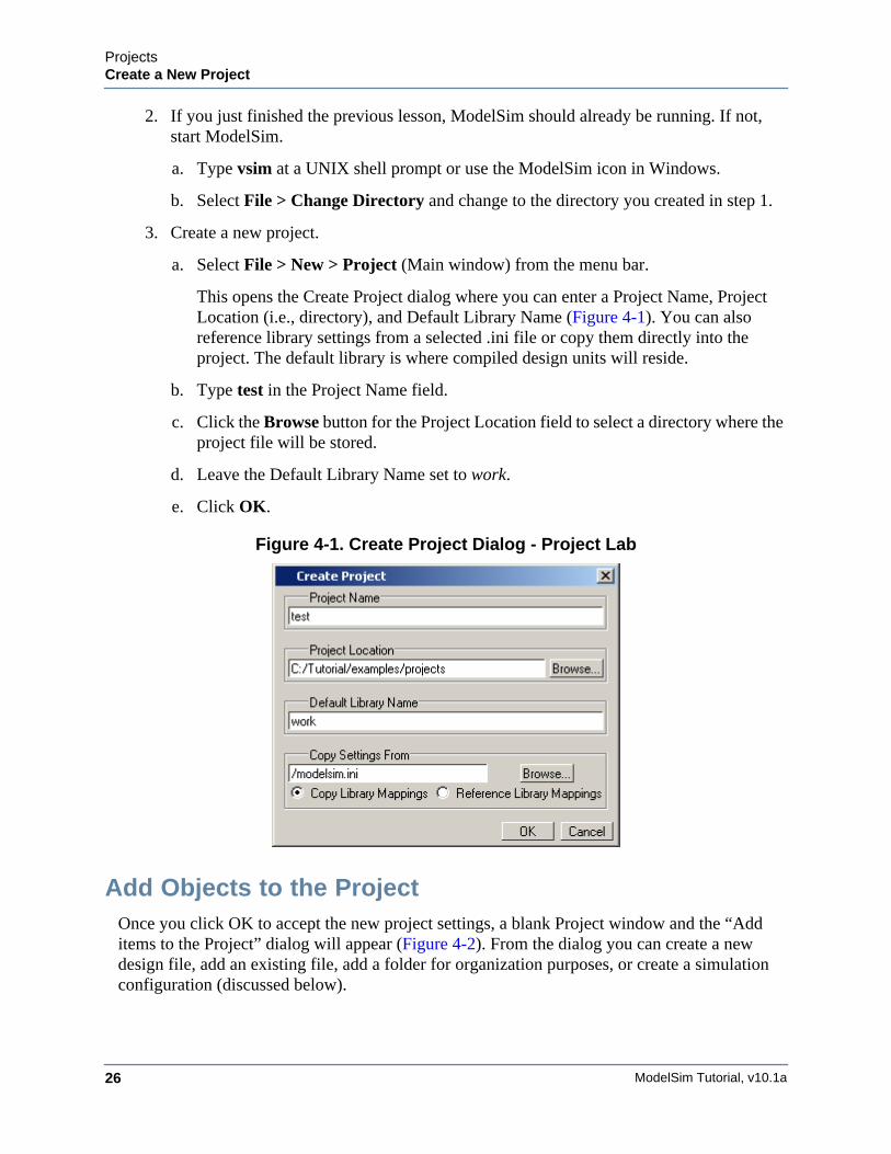
a. Select File > New > Project (Main window) from the menu bar.
This opens the Create Project dialog where you can enter a Project Name, Project Location (i.e., directory), and Default Library Name (Figure 4-1). You can also reference library settings from a selected .ini file or copy them directly into the project. The default library is where compiled design units will reside.
b. Type test in the Project Name field.
c. Click the Browse button for the Project Location field to select a directory where the project file will be stored.
d. Leave the Default Library Name set to work.
e. Click OK.
Figure 4-1. Create Project Dialog - Project Lab
Add Objects to the ProjectOnce you click OK to accept the new project settings, a blank Project window and the “Add items to the Project” dialog will appear (Figure 4-2). From the dialog you can create a new design file, add an existing file, add a folder for organization purposes, or create a simulation configuration (discussed below).
ProjectsCreate a New Project
ModelSim Tutorial, v10.1a 27
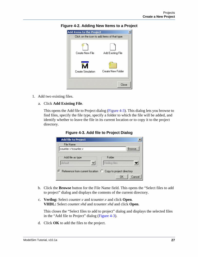
Figure 4-2. Adding New Items to a Project
1. Add two existing files.
a. Click Add Existing File.
This opens the Add file to Project dialog (Figure 4-3). This dialog lets you browse to find files, specify the file type, specify a folder to which the file will be added, and identify whether to leave the file in its current location or to copy it to the project directory.
Figure 4-3. Add file to Project Dialog
b. Click the Browse button for the File Name field. This opens the “Select files to add to project” dialog and displays the contents of the current directory.
c. Verilog: Select counter.v and tcounter.v and click Open.VHDL: Select counter.vhd and tcounter.vhd and click Open.
This closes the “Select files to add to project” dialog and displays the selected files in the “Add file to Project” dialog (Figure 4-3).
d. Click OK to add the files to the project.
ModelSim Tutorial, v10.1a28
ProjectsCreate a New Project
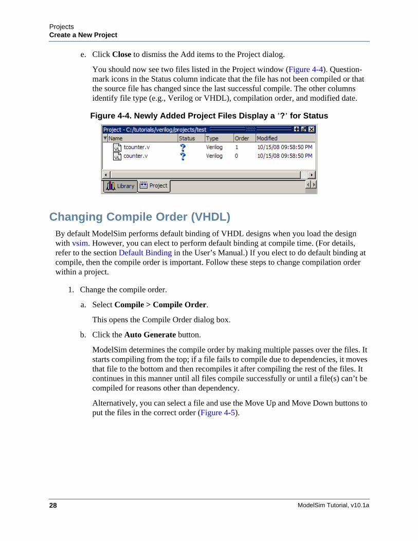
e. Click Close to dismiss the Add items to the Project dialog.
You should now see two files listed in the Project window (Figure 4-4). Question-mark icons in the Status column indicate that the file has not been compiled or that the source file has changed since the last successful compile. The other columns identify file type (e.g., Verilog or VHDL), compilation order, and modified date.
Figure 4-4. Newly Added Project Files Display a ’?’ for Status
Changing Compile Order (VHDL)By default ModelSim performs default binding of VHDL designs when you load the design with vsim. However, you can elect to perform default binding at compile time. (For details, refer to the section Default Binding in the User’s Manual.) If you elect to do default binding at compile, then the compile order is important. Follow these steps to change compilation order within a project.
1. Change the compile order.
a. Select Compile > Compile Order.
This opens the Compile Order dialog box.
b. Click the Auto Generate button.
ModelSim determines the compile order by making multiple passes over the files. It starts compiling from the top; if a file fails to compile due to dependencies, it moves that file to the bottom and then recompiles it after compiling the rest of the files. It continues in this manner until all files compile successfully or until a file(s) can’t be compiled for reasons other than dependency.
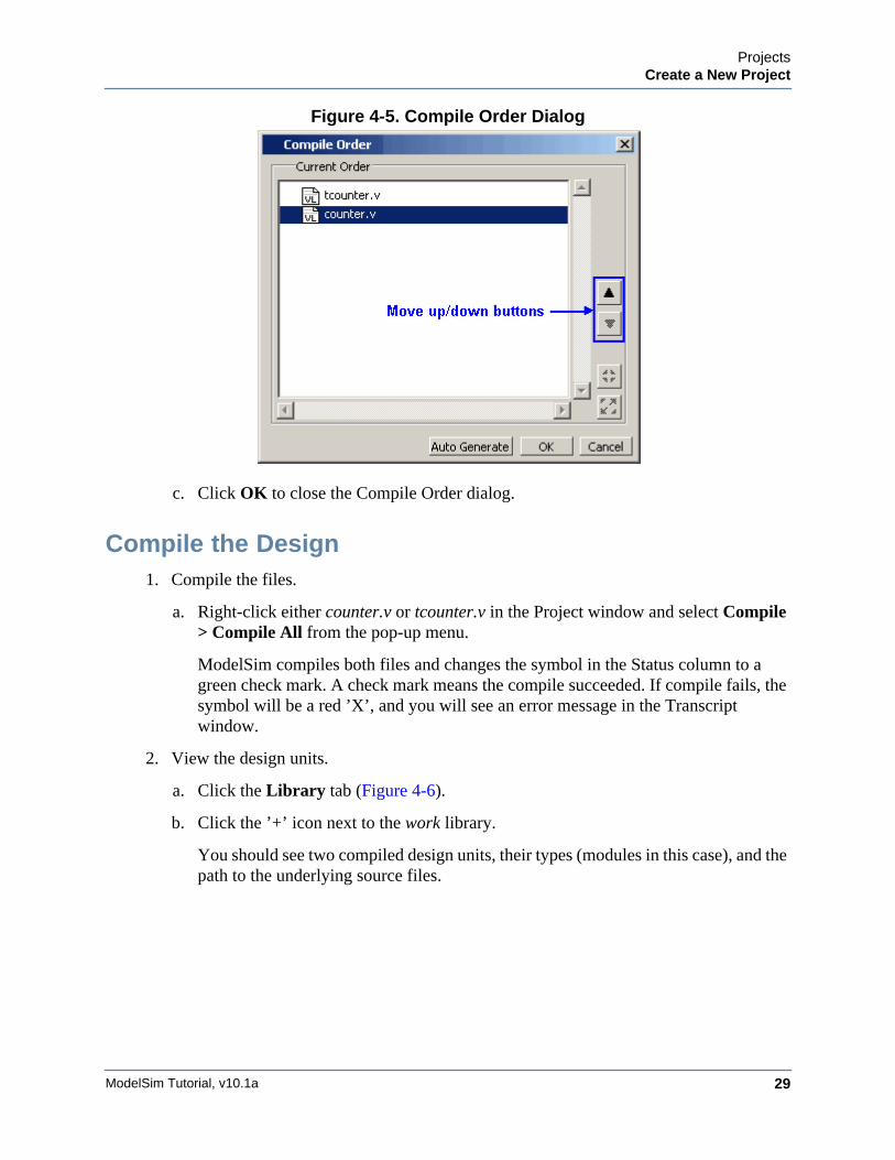
Alternatively, you can select a file and use the Move Up and Move Down buttons to put the files in the correct order (Figure 4-5).
ProjectsCreate a New Project
ModelSim Tutorial, v10.1a 29
Figure 4-5. Compile Order Dialog
c. Click OK to close the Compile Order dialog.
Compile the Design1. Compile the files.
a. Right-click either counter.v or tcounter.v in the Project window and select Compile > Compile All from the pop-up menu.
ModelSim compiles both files and changes the symbol in the Status column to a green check mark. A check mark means the compile succeeded. If compile fails, the symbol will be a red ’X’, and you will see an error message in the Transcript window.
2. View the design units.
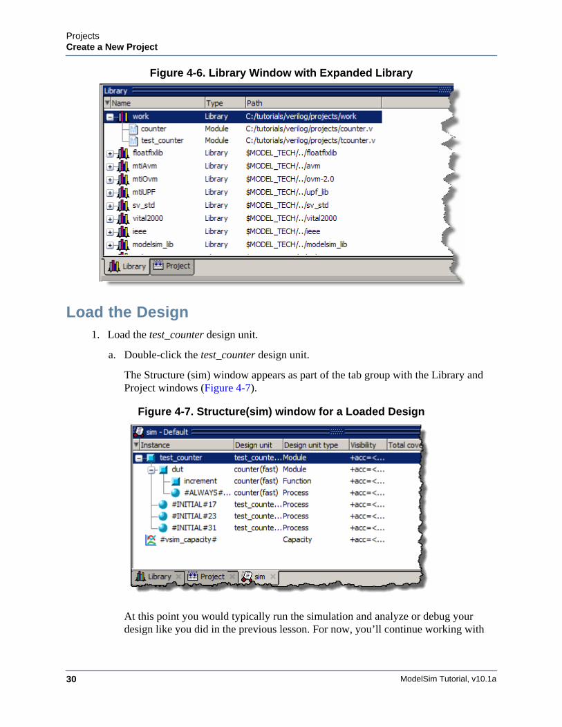
a. Click the Library tab (Figure 4-6).
b. Click the ’+’ icon next to the work library.
You should see two compiled design units, their types (modules in this case), and the path to the underlying source files.
ModelSim Tutorial, v10.1a30
ProjectsCreate a New Project
Figure 4-6. Library Window with Expanded Library
Load the Design1. Load the test_counter design unit.
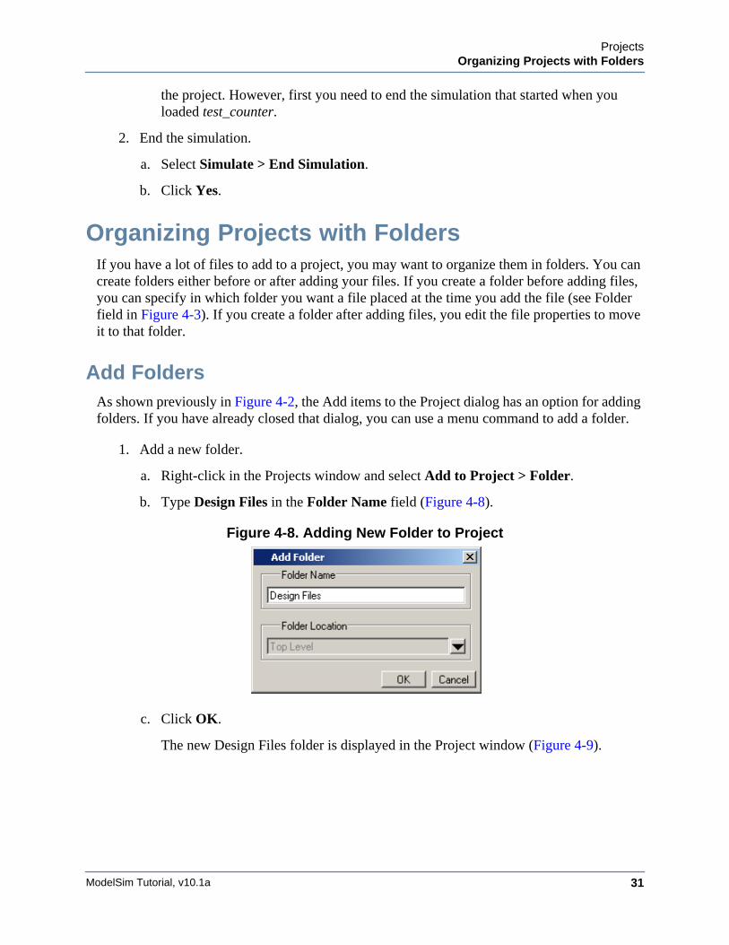
a. Double-click the test_counter design unit.
The Structure (sim) window appears as part of the tab group with the Library and Project windows (Figure 4-7).
Figure 4-7. Structure(sim) window for a Loaded Design
At this point you would typically run the simulation and analyze or debug your design like you did in the previous lesson. For now, you’ll continue working with
ProjectsOrganizing Projects with Folders
ModelSim Tutorial, v10.1a 31
the project. However, first you need to end the simulation that started when you loaded test_counter.
2. End the simulation.
a. Select Simulate > End Simulation.
b. Click Yes.
Organizing Projects with FoldersIf you have a lot of files to add to a project, you may want to organize them in folders. You can create folders either before or after adding your files. If you create a folder before adding files, you can specify in which folder you want a file placed at the time you add the file (see Folder field in Figure 4-3). If you create a folder after adding files, you edit the file properties to move it to that folder.
Add FoldersAs shown previously in Figure 4-2, the Add items to the Project dialog has an option for adding folders. If you have already closed that dialog, you can use a menu command to add a folder.
1. Add a new folder.
a. Right-click in the Projects window and select Add to Project > Folder.
b. Type Design Files in the Folder Name field (Figure 4-8).
Figure 4-8. Adding New Folder to Project
c. Click OK.
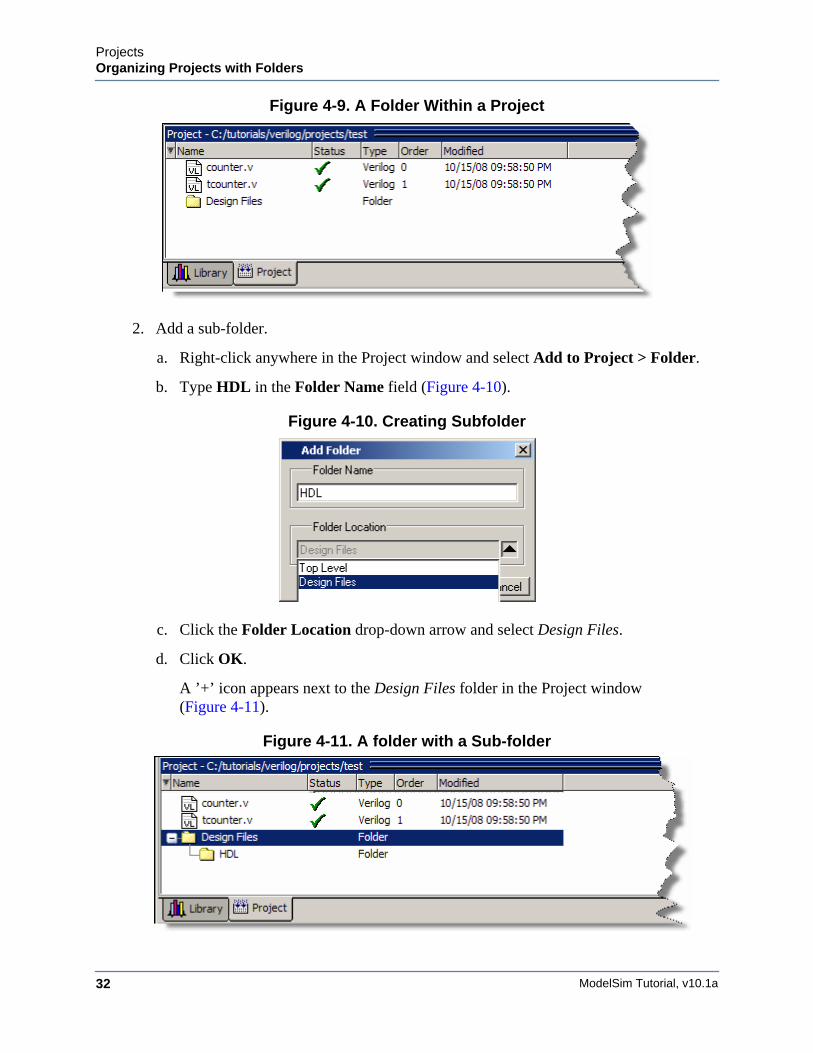
The new Design Files folder is displayed in the Project window (Figure 4-9).
ModelSim Tutorial, v10.1a32
ProjectsOrganizing Projects with Folders
Figure 4-9. A Folder Within a Project
2. Add a sub-folder.
a. Right-click anywhere in the Project window and select Add to Project > Folder.
b. Type HDL in the Folder Name field (Figure 4-10).
Figure 4-10. Creating Subfolder
c. Click the Folder Location drop-down arrow and select Design Files.
d. Click OK.
A ’+’ icon appears next to the Design Files folder in the Project window (Figure 4-11).
Figure 4-11. A folder with a Sub-folder
ProjectsSimulation Configurations
ModelSim Tutorial, v10.1a 33
e. Click the ’+’ icon to see the HDL sub-folder.
Moving Files to FoldersIf you don’t place files into a folder when you first add the files to the project, you can move them into a folder using the properties dialog.
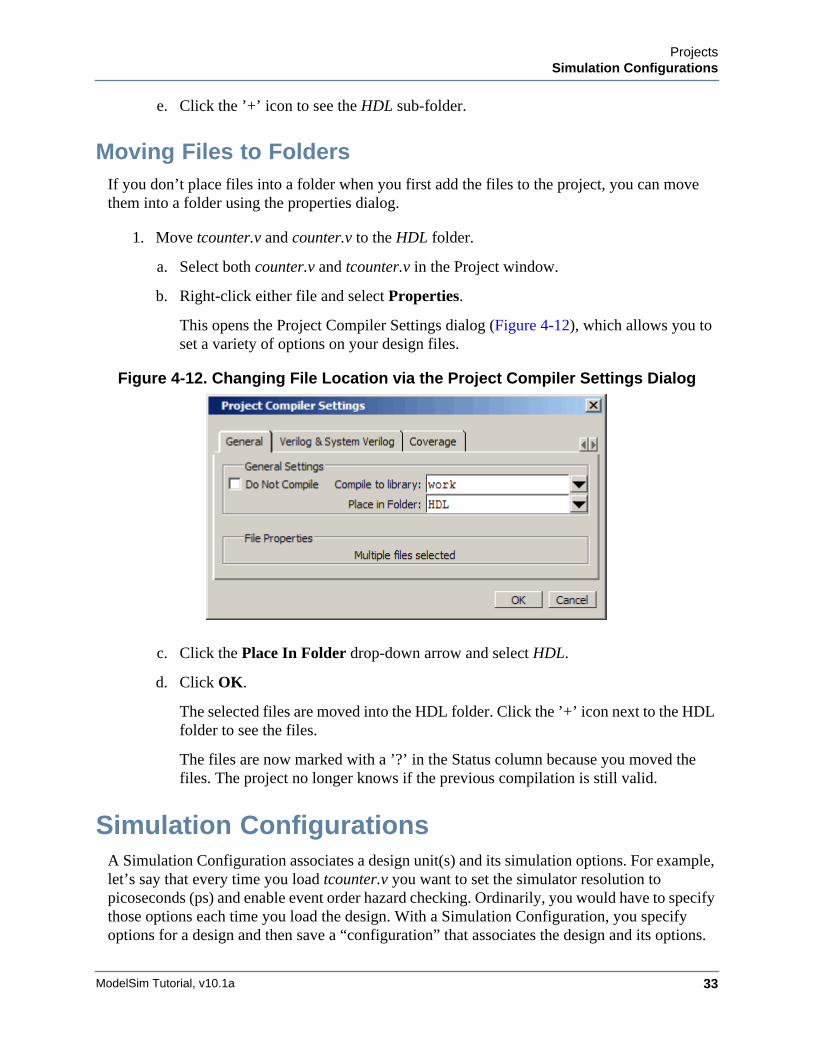
1. Move tcounter.v and counter.v to the HDL folder.
a. Select both counter.v and tcounter.v in the Project window.
b. Right-click either file and select Properties.
This opens the Project Compiler Settings dialog (Figure 4-12), which allows you to set a variety of options on your design files.
Figure 4-12. Changing File Location via the Project Compiler Settings Dialog
c. Click the Place In Folder drop-down arrow and select HDL.
d. Click OK.
The selected files are moved into the HDL folder. Click the ’+’ icon next to the HDL folder to see the files.
The files are now marked with a ’?’ in the Status column because you moved the files. The project no longer knows if the previous compilation is still valid.
Simulation ConfigurationsA Simulation Configuration associates a design unit(s) and its simulation options. For example, let’s say that every time you load tcounter.v you want to set the simulator resolution to picoseconds (ps) and enable event order hazard checking. Ordinarily, you would have to specify those options each time you load the design. With a Simulation Configuration, you specify options for a design and then save a “configuration” that associates the design and its options.
ModelSim Tutorial, v10.1a34
ProjectsSimulation Configurations
The configuration is then listed in the Project window and you can double-click it to load tcounter.v along with its options.
1. Create a new Simulation Configuration.
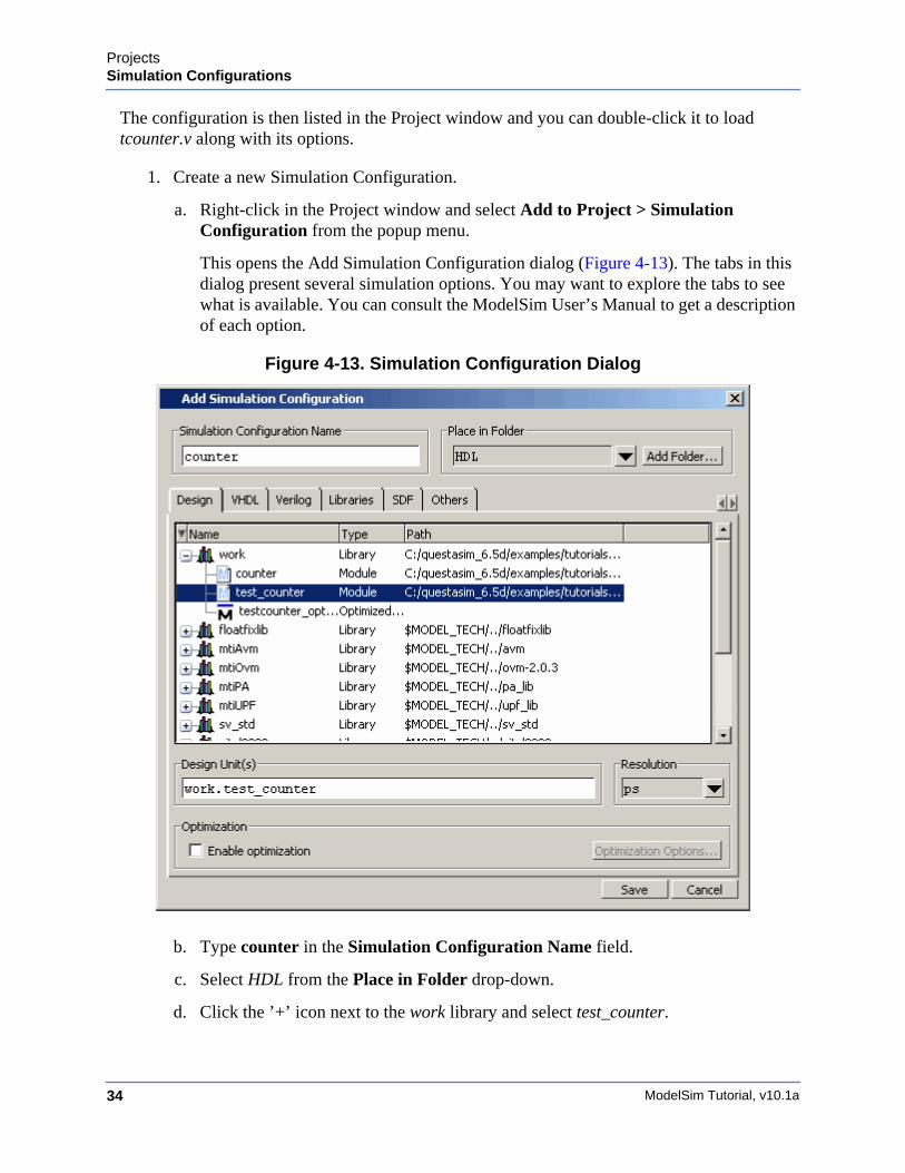
a. Right-click in the Project window and select Add to Project > Simulation Configuration from the popup menu.
This opens the Add Simulation Configuration dialog (Figure 4-13). The tabs in this dialog present several simulation options. You may want to explore the tabs to see what is available. You can consult the ModelSim User’s Manual to get a description of each option.
Figure 4-13. Simulation Configuration Dialog
b. Type counter in the Simulation Configuration Name field.
c. Select HDL from the Place in Folder drop-down.
d. Click the ’+’ icon next to the work library and select test_counter.
ProjectsSimulation Configurations
ModelSim Tutorial, v10.1a 35
e. Click the Resolution drop-down and select ps.
f. For Verilog, click the Verilog tab and check Enable hazard checking (-hazards).
g. Click Save.
The files tcounter.v and counter.v show question mark icons in the status column because they have changed location since they were last compiled and need to be recompiled.
h. Select one of the files, tcounter.v or counter.v.
i. Select Compile > Compile All.
The Project window now shows a Simulation Configuration named counter in the HDL folder (Figure 4-14).
Figure 4-14. A Simulation Configuration in the Project window
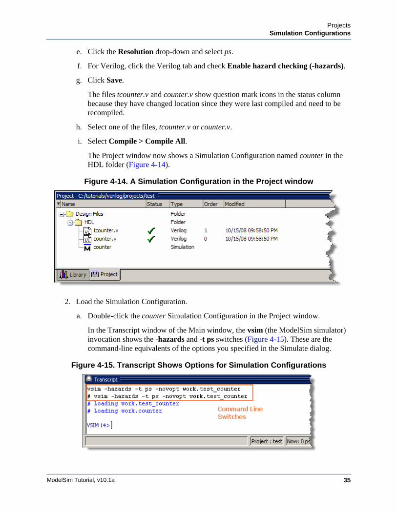
2. Load the Simulation Configuration.
a. Double-click the counter Simulation Configuration in the Project window.
In the Transcript window of the Main window, the vsim (the ModelSim simulator) invocation shows the -hazards and -t ps switches (Figure 4-15). These are the command-line equivalents of the options you specified in the Simulate dialog.
Figure 4-15. Transcript Shows Options for Simulation Configurations
ModelSim Tutorial, v10.1a36
ProjectsSimulation Configurations
Lesson Wrap-Up
This concludes this lesson. Before continuing you need to end the current simulation and close the current project.
1. Select Simulate > End Simulation. Click Yes.
2. In the Project window, right-click and select Close Project.
If you do not close the project, it will open automatically the next time you start ModelSim.
ModelSim Tutorial, v10.1a 37
Chapter 5Working With Multiple Libraries
Introduction
In this lesson you will practice working with multiple libraries. You might have multiple libraries to organize your design, to access IP from a third-party source, or to share common parts between simulations.
You will start the lesson by creating a resource library that contains the counter design unit. Next, you will create a project and compile the test bench into it. Finally, you will link to the library containing the counter and then run the simulation.
Design Files for this Lesson
The sample design for this lesson is a simple 8-bit, binary up-counter with an associated test bench. The pathnames are as follows:
Verilog – <install_dir>/examples/tutorials/verilog/libraries/counter.v and tcounter.v
VHDL – <install_dir>/examples/tutorials/vhdl/libraries/counter.vhd and tcounter.vhd
This lesson uses the Verilog files tcounter.v and counter.v in the examples. If you have a VHDL license, use tcounter.vhd and counter.vhd instead.
Related Reading
User’s Manual Chapter: Design Libraries.
Creating the Resource LibraryBefore creating the resource library, make sure the modelsim.ini in your install directory is “Read Only.” This will prevent permanent mapping of resource libraries to the master modelsim.ini file. See Permanently Mapping VHDL Resource Libraries.
1. Create a directory for the resource library.
Create a new directory called resource_library. Copy counter.v from <install_dir>/examples/tutorials/verilog/libraries to the new directory.
2. Create a directory for the test bench.
ModelSim Tutorial, v10.1a38
Working With Multiple LibrariesCreating the Resource Library
Create a new directory called testbench that will hold the test bench and project files. Copy tcounter.v from <install_dir>/examples/tutorials/verilog/libraries to the new directory.
You are creating two directories in this lesson to mimic the situation where you receive a resource library from a third-party. As noted earlier, we will link to the resource library in the first directory later in the lesson.
3. Start ModelSim and change to the resource_library directory.
If you just finished the previous lesson, ModelSim should already be running. If not, start ModelSim.
a. Type vsim at a UNIX shell prompt or use the ModelSim icon in Windows.
If the Welcome to ModelSim dialog appears, click Close.
b. Select File > Change Directory and change to the resource_library directory you created in step 1.
4. Create the resource library.
a. Select File > New > Library.
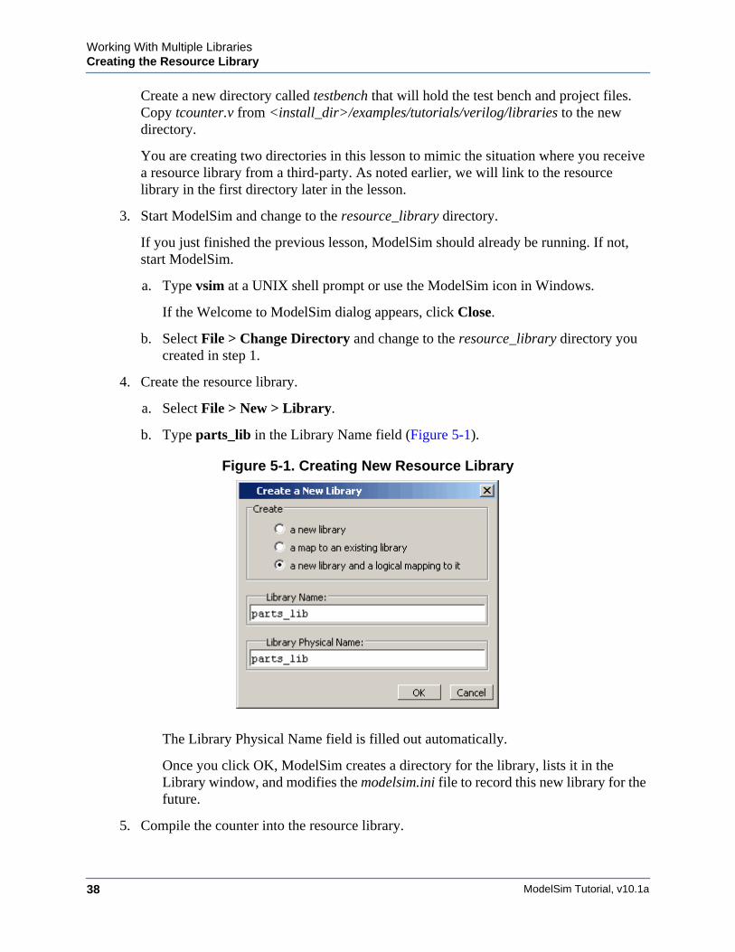
b. Type parts_lib in the Library Name field (Figure 5-1).
Figure 5-1. Creating New Resource Library
The Library Physical Name field is filled out automatically.
Once you click OK, ModelSim creates a directory for the library, lists it in the Library window, and modifies the modelsim.ini file to record this new library for the future.
5. Compile the counter into the resource library.
Working With Multiple LibrariesCreating the Project
ModelSim Tutorial, v10.1a 39
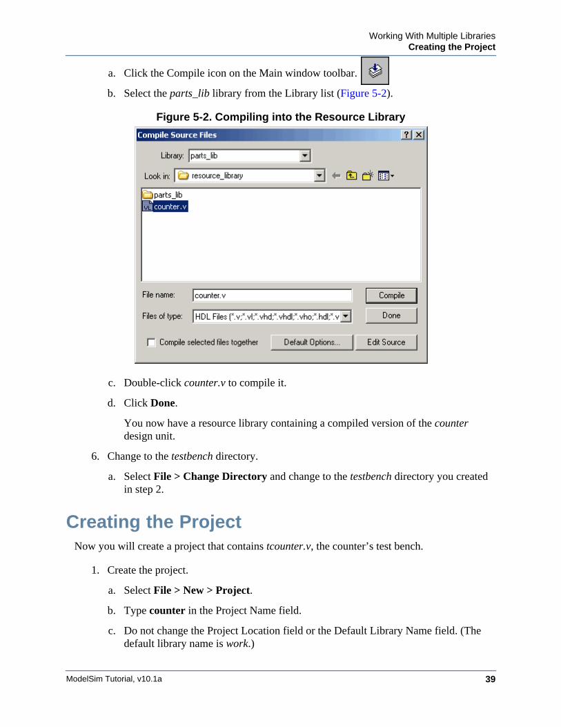
a. Click the Compile icon on the Main window toolbar.
b. Select the parts_lib library from the Library list (Figure 5-2).
Figure 5-2. Compiling into the Resource Library
c. Double-click counter.v to compile it.
d. Click Done.
You now have a resource library containing a compiled version of the counter design unit.
6. Change to the testbench directory.
a. Select File > Change Directory and change to the testbench directory you created in step 2.
Creating the ProjectNow you will create a project that contains tcounter.v, the counter’s test bench.
1. Create the project.
a. Select File > New > Project.
b. Type counter in the Project Name field.
c. Do not change the Project Location field or the Default Library Name field. (The default library name is work.)
ModelSim Tutorial, v10.1a40
Working With Multiple LibrariesLinking to the Resource Library
d. Make sure “Copy Library Mappings” is selected. The default modelsim.ini file will be used.
e. Click OK.
2. Add the test bench to the project.
a. Click Add Existing File in the Add items to the Project dialog.
b. Click the Browse button and select tcounter.v in the “Select files to add to project” dialog.
c. Click Open.
d. Click OK.
e. Click Close to dismiss the “Add items to the Project” dialog.
The tcounter.v file is listed in the Project window.
3. Compile the test bench.
a. Right-click tcounter.v and select Compile > Compile Selected.
Linking to the Resource LibraryTo wrap up this part of the lesson, you will link to the parts_lib library you created earlier. But first, try loading the test bench without the link and see what happens.
ModelSim responds differently for Verilog and VHDL in this situation.
Verilog
Load the Verilog Test Bench
1. Load a Verilog design with a missing resource library.
a. In the Library window, click the ’+’ icon next to the work library and double-click test_counter.
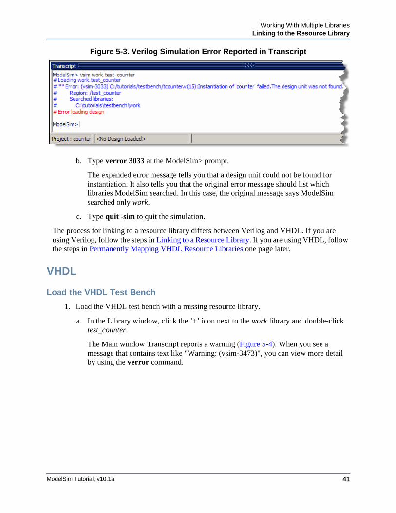
The Transcript reports an error (Figure 5-3). When you see a message that contains text like "Error: (vsim-3033)", you can view more detail by using the verror command.
Working With Multiple LibrariesLinking to the Resource Library
ModelSim Tutorial, v10.1a 41
Figure 5-3. Verilog Simulation Error Reported in Transcript
b. Type verror 3033 at the ModelSim> prompt.
The expanded error message tells you that a design unit could not be found for instantiation. It also tells you that the original error message should list which libraries ModelSim searched. In this case, the original message says ModelSim searched only work.
c. Type quit -sim to quit the simulation.
The process for linking to a resource library differs between Verilog and VHDL. If you are using Verilog, follow the steps in Linking to a Resource Library. If you are using VHDL, follow the steps in Permanently Mapping VHDL Resource Libraries one page later.
VHDL
Load the VHDL Test Bench
1. Load the VHDL test bench with a missing resource library.
a. In the Library window, click the ’+’ icon next to the work library and double-click test_counter.
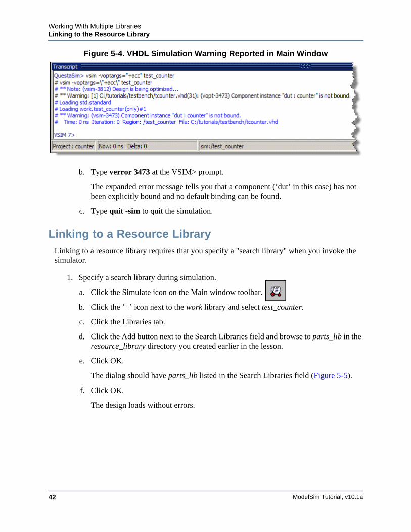
The Main window Transcript reports a warning (Figure 5-4). When you see a message that contains text like "Warning: (vsim-3473)", you can view more detail by using the verror command.
ModelSim Tutorial, v10.1a42
Working With Multiple LibrariesLinking to the Resource Library
Figure 5-4. VHDL Simulation Warning Reported in Main Window
b. Type verror 3473 at the VSIM> prompt.
The expanded error message tells you that a component (’dut’ in this case) has not been explicitly bound and no default binding can be found.
c. Type quit -sim to quit the simulation.
Linking to a Resource LibraryLinking to a resource library requires that you specify a "search library" when you invoke the simulator.
1. Specify a search library during simulation.
a. Click the Simulate icon on the Main window toolbar.
b. Click the ’+’ icon next to the work library and select test_counter.
c. Click the Libraries tab.
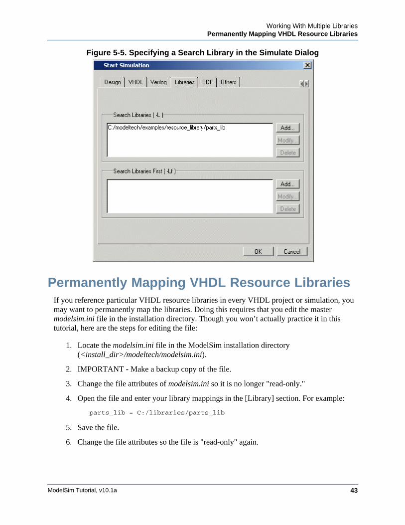
d. Click the Add button next to the Search Libraries field and browse to parts_lib in the resource_library directory you created earlier in the lesson.
e. Click OK.
The dialog should have parts_lib listed in the Search Libraries field (Figure 5-5).
f. Click OK.
The design loads without errors.
Working With Multiple LibrariesPermanently Mapping VHDL Resource Libraries
ModelSim Tutorial, v10.1a 43
Figure 5-5. Specifying a Search Library in the Simulate Dialog
Permanently Mapping VHDL Resource LibrariesIf you reference particular VHDL resource libraries in every VHDL project or simulation, you may want to permanently map the libraries. Doing this requires that you edit the master modelsim.ini file in the installation directory. Though you won’t actually practice it in this tutorial, here are the steps for editing the file:
1. Locate the modelsim.ini file in the ModelSim installation directory (<install_dir>/modeltech/modelsim.ini).
2. IMPORTANT - Make a backup copy of the file.
3. Change the file attributes of modelsim.ini so it is no longer "read-only."
4. Open the file and enter your library mappings in the [Library] section. For example:
parts_lib = C:/libraries/parts_lib
5. Save the file.
6. Change the file attributes so the file is "read-only" again.

ModelSim Tutorial, v10.1a44
Working With Multiple LibrariesPermanently Mapping VHDL Resource Libraries
Lesson Wrap-Up
This concludes this lesson. Before continuing we need to end the current simulation and close the project.
1. Select Simulate > End Simulation. Click Yes.
2. Select the Project window to make it active.
3. Select File > Close. Click OK.
ModelSim Tutorial, v10.1a 45
Chapter 6Analyzing Waveforms
Introduction
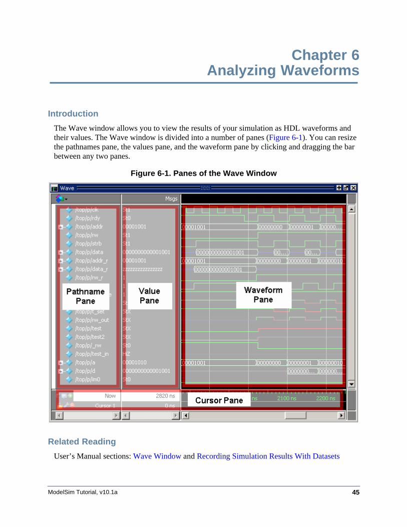
The Wave window allows you to view the results of your simulation as HDL waveforms and their values. The Wave window is divided into a number of panes (Figure 6-1). You can resize the pathnames pane, the values pane, and the waveform pane by clicking and dragging the bar between any two panes.
Figure 6-1. Panes of the Wave Window
Related Reading
User’s Manual sections: Wave Window and Recording Simulation Results With Datasets
ModelSim Tutorial, v10.1a46
Analyzing WaveformsLoading a Design
Loading a DesignFor the examples in this lesson, we will use the design simulated in Basic Simulation.
1. If you just finished the previous lesson, ModelSim should already be running. If not, start ModelSim.
a. Type vsim at a UNIX shell prompt or use the ModelSim icon in Windows.
If the Welcome to ModelSim dialog appears, click Close.
2. Load the design.
a. Select File > Change Directory and open the directory you created in the “Basic Simulation” lesson.
The work library should already exist.
b. Click the ’+’ icon next to the work library and double-click test_counter.
ModelSim loads the design and opens a Structure (sim) window.
Add Objects to the Wave WindowModelSim offers several methods for adding objects to the Wave window. In this exercise, you will try different methods.
1. Add objects from the Objects window.
a. Open an Objects window by selecting View > Objects.
b. Select an item in the Objects window, right-click, and then select Add > To Wave > Signals in Region.
ModelSim opens a Wave window and displays signals in the region.
c. Place the cursor over an object and click the middle mouse button to place an object in the Wave window.
d. Select a group of objects then click the middle mouse button while the cursor is placed over the group.
2. Undock the Wave window.
By default ModelSim opens the Wave window in the right side of the Main window. You can change the default via the Preferences dialog (Tools > Edit Preferences). Refer to the Simulator GUI Preferences section in the User’s Manual for more information.
a. Click the undock icon on the Wave window.
Analyzing WaveformsZooming the Waveform Display
ModelSim Tutorial, v10.1a 47
The Wave window becomes a standalone, un-docked window. Resize the window as needed.
3. Add objects using drag-and-drop.
You can drag an object to the Wave window from many other windows (e.g., Structure, Objects, and Locals).
a. In the Wave window, select Edit > Select All and then Edit > Delete.
b. Drag an instance from the Structure (sim) window to the Wave window.
ModelSim adds the objects for that instance to the Wave window.
c. Drag a signal from the Objects window to the Wave window.
d. In the Wave window, select Edit > Select All and then Edit > Delete.
4. Add objects using the add wave command.
a. Type the following at the VSIM> prompt.
add wave *
ModelSim adds all objects from the current region.
b. Run the simulation for 500 ns so you can see waveforms.
Zooming the Waveform DisplayThere are numerous methods for zooming the Waveform display.
1. Zoom the display using various techniques.
a. Click the Zoom Mode icon on the Wave window toolbar.
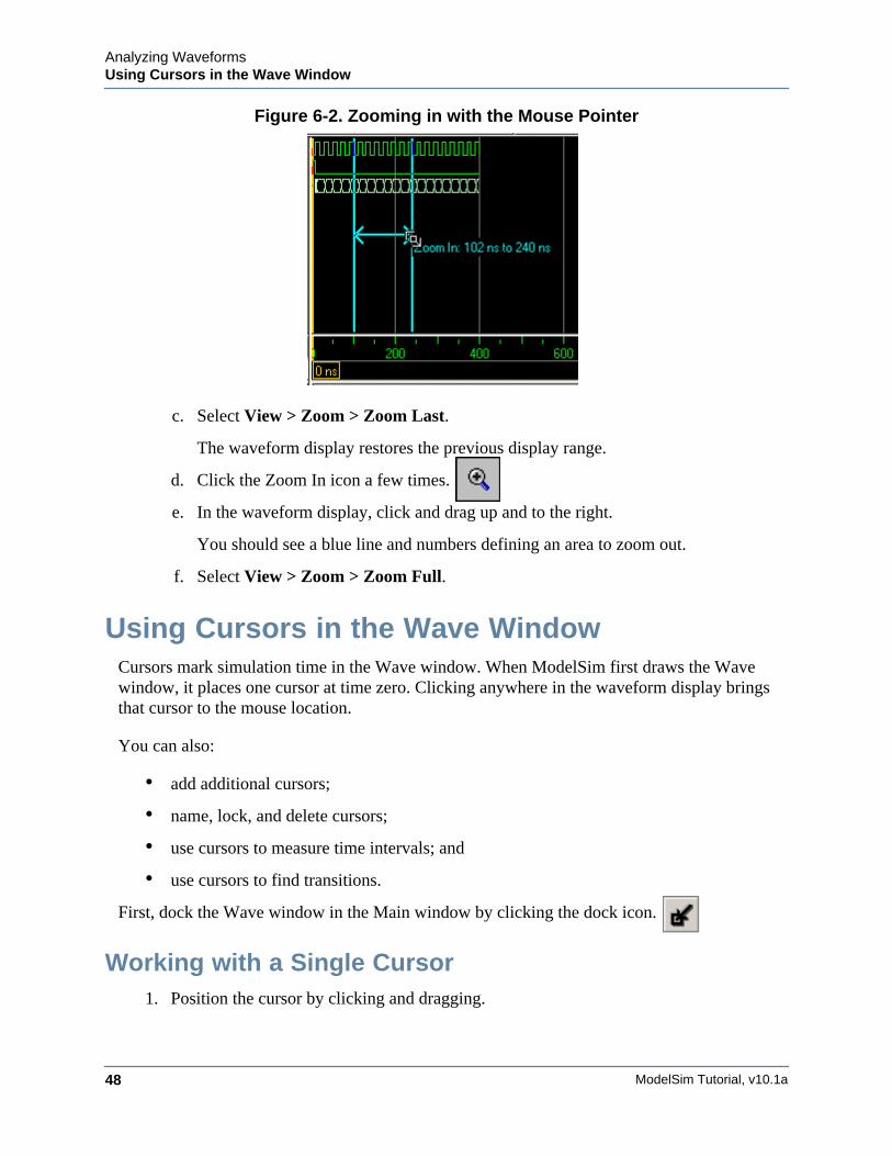
b. In the waveform display, click and drag down and to the right.
You should see blue vertical lines and numbers defining an area to zoom in (Figure 6-2).
ModelSim Tutorial, v10.1a48
Analyzing WaveformsUsing Cursors in the Wave Window
Figure 6-2. Zooming in with the Mouse Pointer
c. Select View > Zoom > Zoom Last.
The waveform display restores the previous display range.
d. Click the Zoom In icon a few times.
e. In the waveform display, click and drag up and to the right.
You should see a blue line and numbers defining an area to zoom out.
f. Select View > Zoom > Zoom Full.
Using Cursors in the Wave WindowCursors mark simulation time in the Wave window. When ModelSim first draws the Wave window, it places one cursor at time zero. Clicking anywhere in the waveform display brings that cursor to the mouse location.
You can also:
• add additional cursors;
• name, lock, and delete cursors;
• use cursors to measure time intervals; and
• use cursors to find transitions.
First, dock the Wave window in the Main window by clicking the dock icon.
Working with a Single Cursor1. Position the cursor by clicking and dragging.
Analyzing WaveformsUsing Cursors in the Wave Window
ModelSim Tutorial, v10.1a 49
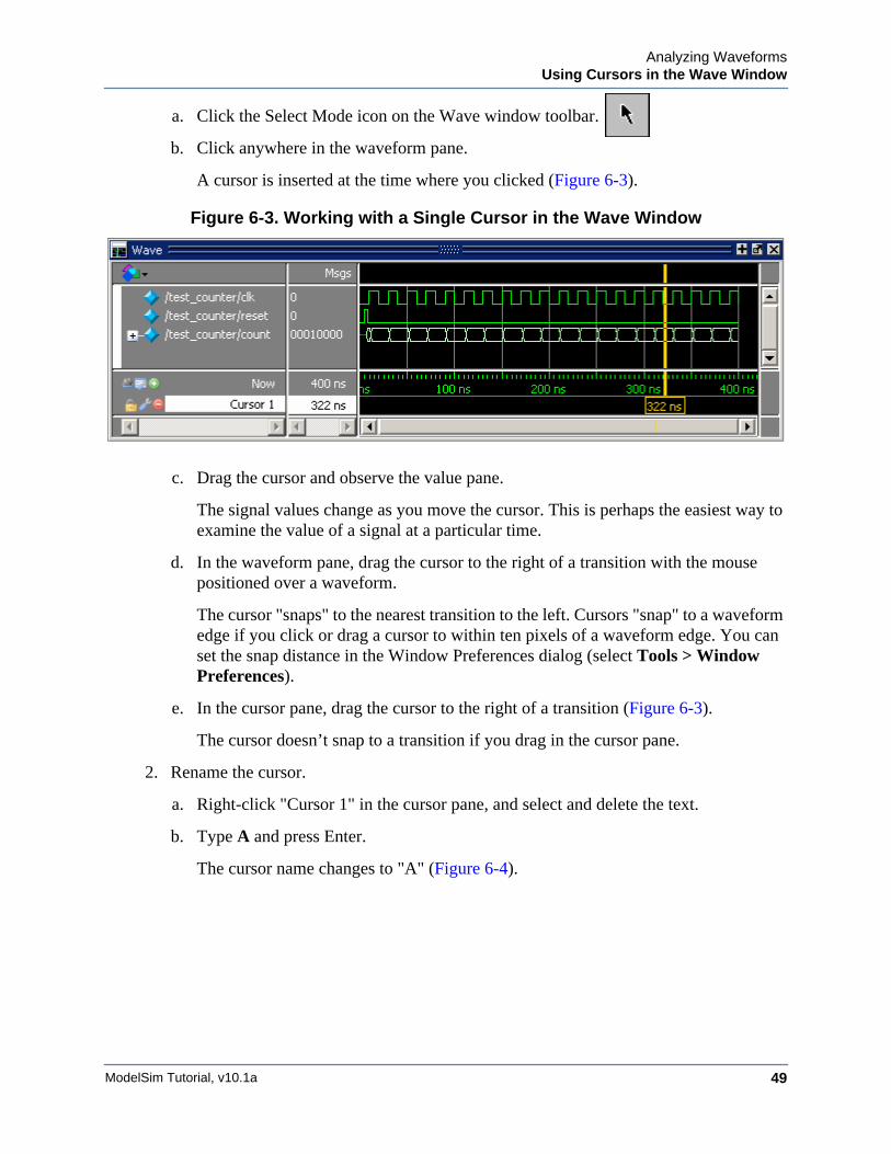
a. Click the Select Mode icon on the Wave window toolbar.
b. Click anywhere in the waveform pane.
A cursor is inserted at the time where you clicked (Figure 6-3).
Figure 6-3. Working with a Single Cursor in the Wave Window
c. Drag the cursor and observe the value pane.
The signal values change as you move the cursor. This is perhaps the easiest way to examine the value of a signal at a particular time.
d. In the waveform pane, drag the cursor to the right of a transition with the mouse positioned over a waveform.
The cursor "snaps" to the nearest transition to the left. Cursors "snap" to a waveform edge if you click or drag a cursor to within ten pixels of a waveform edge. You can set the snap distance in the Window Preferences dialog (select Tools > Window Preferences).
e. In the cursor pane, drag the cursor to the right of a transition (Figure 6-3).
The cursor doesn’t snap to a transition if you drag in the cursor pane.
2. Rename the cursor.
a. Right-click "Cursor 1" in the cursor pane, and select and delete the text.
b. Type A and press Enter.
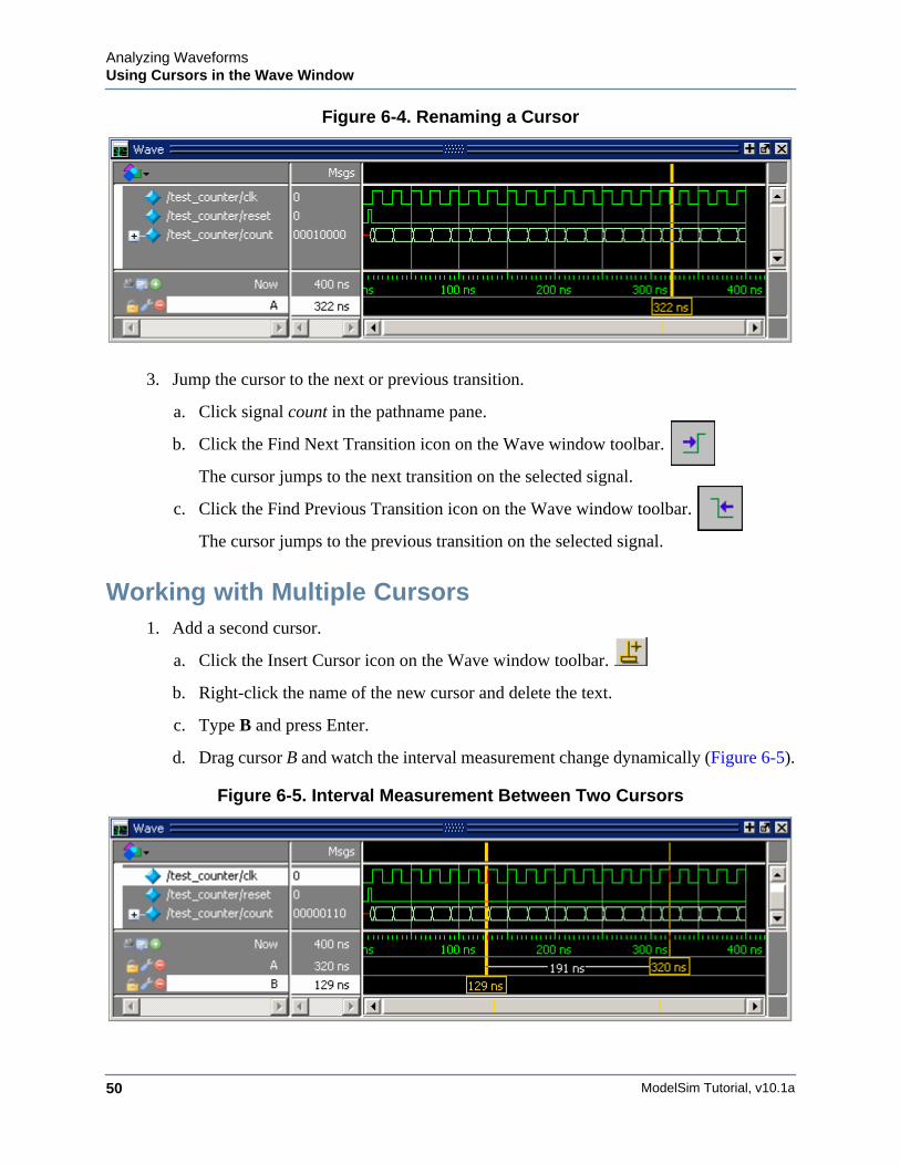
The cursor name changes to "A" (Figure 6-4).
ModelSim Tutorial, v10.1a50
Analyzing WaveformsUsing Cursors in the Wave Window
Figure 6-4. Renaming a Cursor
3. Jump the cursor to the next or previous transition.
a. Click signal count in the pathname pane.
b. Click the Find Next Transition icon on the Wave window toolbar.
The cursor jumps to the next transition on the selected signal.
c. Click the Find Previous Transition icon on the Wave window toolbar.
The cursor jumps to the previous transition on the selected signal.
Working with Multiple Cursors1. Add a second cursor.
a. Click the Insert Cursor icon on the Wave window toolbar.
b. Right-click the name of the new cursor and delete the text.
c. Type B and press Enter.
d. Drag cursor B and watch the interval measurement change dynamically (Figure 6-5).
Figure 6-5. Interval Measurement Between Two Cursors
Analyzing WaveformsUsing Cursors in the Wave Window
ModelSim Tutorial, v10.1a 51
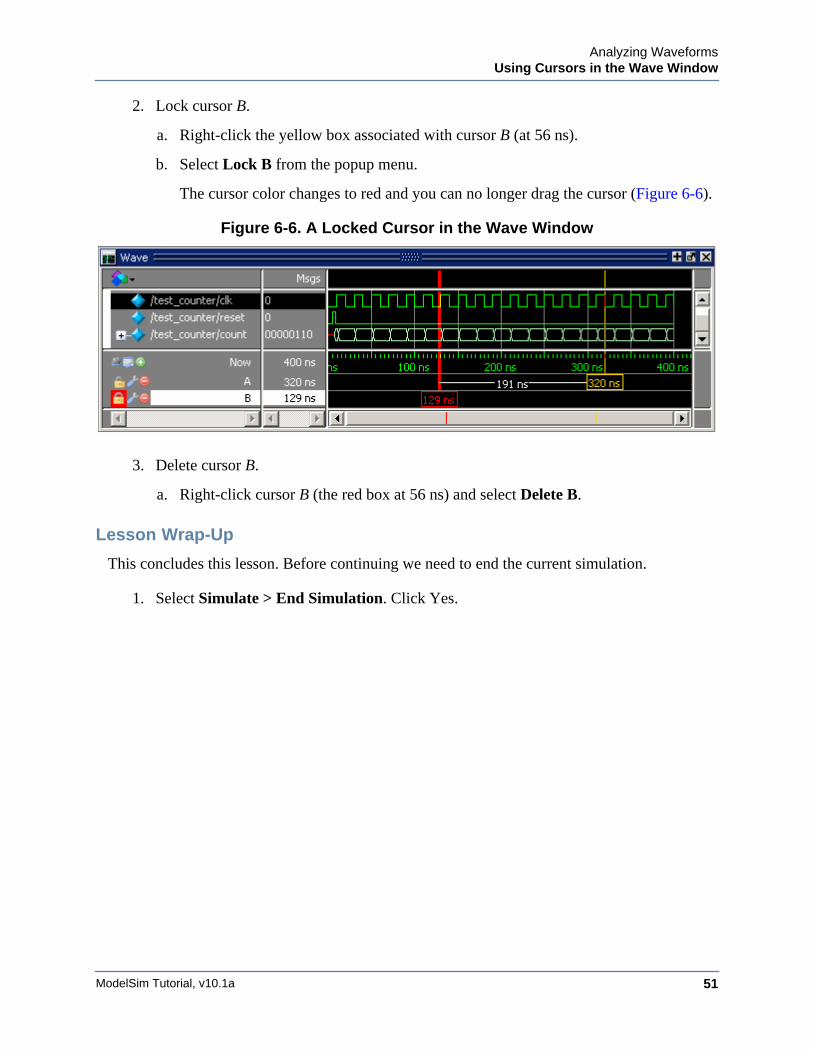
2. Lock cursor B.
a. Right-click the yellow box associated with cursor B (at 56 ns).
b. Select Lock B from the popup menu.
The cursor color changes to red and you can no longer drag the cursor (Figure 6-6).
Figure 6-6. A Locked Cursor in the Wave Window
3. Delete cursor B.
a. Right-click cursor B (the red box at 56 ns) and select Delete B.
Lesson Wrap-Up
This concludes this lesson. Before continuing we need to end the current simulation.
1. Select Simulate > End Simulation. Click Yes.

ModelSim Tutorial, v10.1a52
Analyzing WaveformsUsing Cursors in the Wave Window
ModelSim Tutorial, v10.1a 53
Chapter 7Viewing And Initializing Memories
Introduction
In this lesson you will learn how to view and initialize memories. ModelSim defines and lists any of the following as memories:
• reg, wire, and std_logic arrays
• Integer arrays
• Single dimensional arrays of VHDL enumerated types other than std_logic
Design Files for this Lesson
The installation comes with Verilog and VHDL versions of the example design located in the following directories:
Verilog – <install_dir>/examples/tutorials/verilog/memory
VHDL – <install_dir>/examples/tutorials/vhdl/memory
This lesson uses the Verilog version for the exercises. If you have a VHDL license, use the VHDL version instead.
Related Reading
User’s Manual Section: Memory List Window.
Reference Manual commands: mem display, mem load, mem save, and radix.
Compile and Load the Design
1. Create a new directory and copy the tutorial files into it.
Start by creating a new directory for this exercise (in case other users will be working with these lessons). Create the directory and copy all files from <install_dir>/examples/tutorials/verilog/memory to the new directory.
If you have a VHDL license, copy the files in <install_dir>/examples/tutorials/vhdl/memory instead.
2. Start ModelSim and change to the exercise directory.
ModelSim Tutorial, v10.1a54
Viewing And Initializing MemoriesView a Memory and its Contents
If you just finished the previous lesson, ModelSim should already be running. If not, start ModelSim.
a. Type vsim at a UNIX shell prompt or use the ModelSim icon in Windows.
If the Welcome to ModelSim dialog appears, click Close.
b. Select File > Change Directory and change to the directory you created in step 1.
3. Create the working library and compile the design.
a. Type vlib work at the ModelSim> prompt.
b. Verilog: Type vlog *.v at the ModelSim> prompt to compile all verilog files in the design.
VHDL:Type vcom -93 sp_syn_ram.vhd dp_syn_ram.vhd ram_tb.vhd at the ModelSim> prompt.
4. Load the design.
a. On the Library tab of the Main window Workspace, click the "+" icon next to the work library.
b. Double-click the ram_tb design unit to load the design.
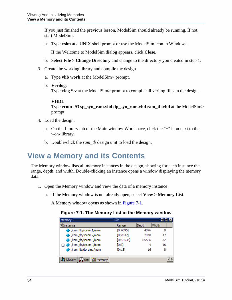
View a Memory and its ContentsThe Memory window lists all memory instances in the design, showing for each instance the range, depth, and width. Double-clicking an instance opens a window displaying the memory data.
1. Open the Memory window and view the data of a memory instance
a. If the Memory window is not already open, select View > Memory List.
A Memory window opens as shown in Figure 7-1.
Figure 7-1. The Memory List in the Memory window
Viewing And Initializing MemoriesView a Memory and its Contents
ModelSim Tutorial, v10.1a 55
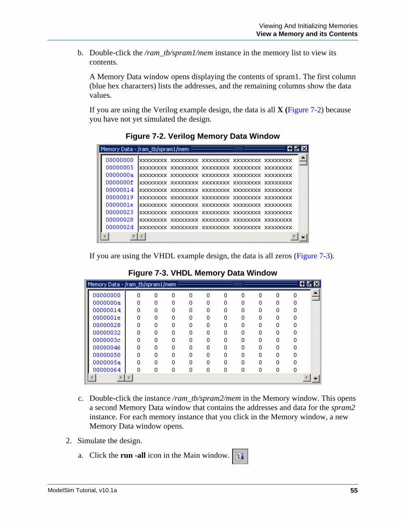
b. Double-click the /ram_tb/spram1/mem instance in the memory list to view its contents.
A Memory Data window opens displaying the contents of spram1. The first column (blue hex characters) lists the addresses, and the remaining columns show the data values.
If you are using the Verilog example design, the data is all X (Figure 7-2) because you have not yet simulated the design.
Figure 7-2. Verilog Memory Data Window
If you are using the VHDL example design, the data is all zeros (Figure 7-3).
Figure 7-3. VHDL Memory Data Window
c. Double-click the instance /ram_tb/spram2/mem in the Memory window. This opens a second Memory Data window that contains the addresses and data for the spram2 instance. For each memory instance that you click in the Memory window, a new Memory Data window opens.
2. Simulate the design.
a. Click the run -all icon in the Main window.
ModelSim Tutorial, v10.1a56
Viewing And Initializing MemoriesView a Memory and its Contents
A Source window opens showing the source code for the ram_tb file at the point where the simulation stopped.
VHDL: In the Transcript window, you will see NUMERIC_STD warnings that can be ignored and an assertion failure that is functioning to stop the simulation. The simulation itself has not failed.
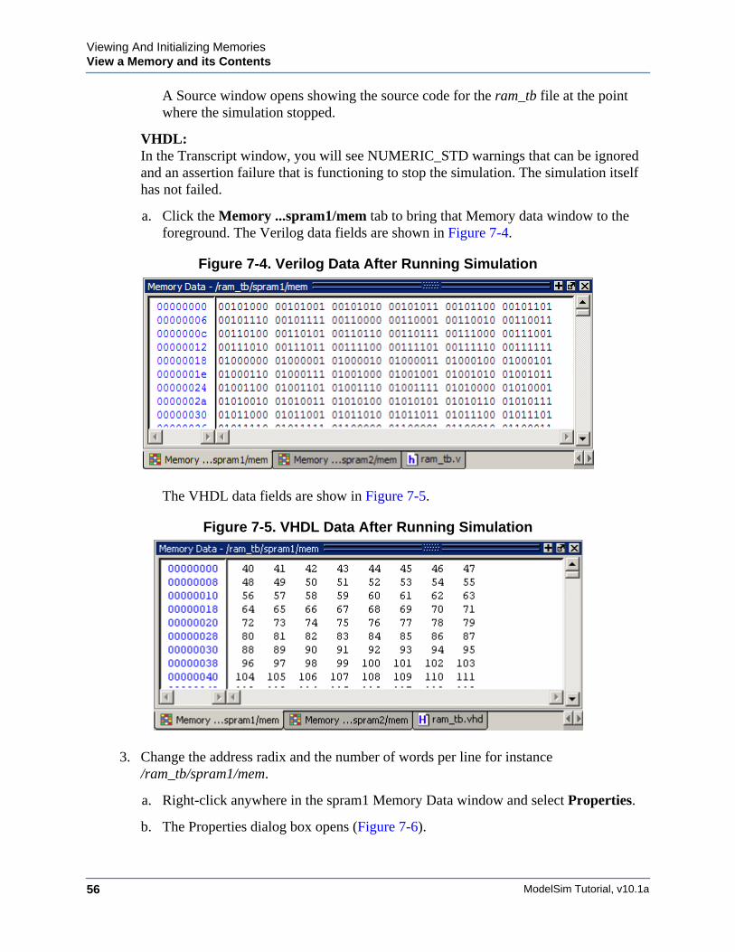
a. Click the Memory ...spram1/mem tab to bring that Memory data window to the foreground. The Verilog data fields are shown in Figure 7-4.
Figure 7-4. Verilog Data After Running Simulation
The VHDL data fields are show in Figure 7-5.
Figure 7-5. VHDL Data After Running Simulation
3. Change the address radix and the number of words per line for instance /ram_tb/spram1/mem.
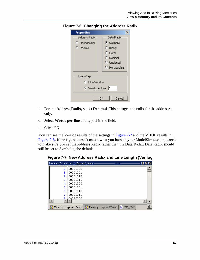
a. Right-click anywhere in the spram1 Memory Data window and select Properties.
b. The Properties dialog box opens (Figure 7-6).
Viewing And Initializing MemoriesView a Memory and its Contents
ModelSim Tutorial, v10.1a 57
Figure 7-6. Changing the Address Radix
c. For the Address Radix, select Decimal. This changes the radix for the addresses only.
d. Select Words per line and type 1 in the field.
e. Click OK.
You can see the Verilog results of the settings in Figure 7-7 and the VHDL results in Figure 7-8. If the figure doesn’t match what you have in your ModelSim session, check to make sure you set the Address Radix rather than the Data Radix. Data Radix should still be set to Symbolic, the default.
Figure 7-7. New Address Radix and Line Length (Verilog
ModelSim Tutorial, v10.1a58
Viewing And Initializing MemoriesView a Memory and its Contents
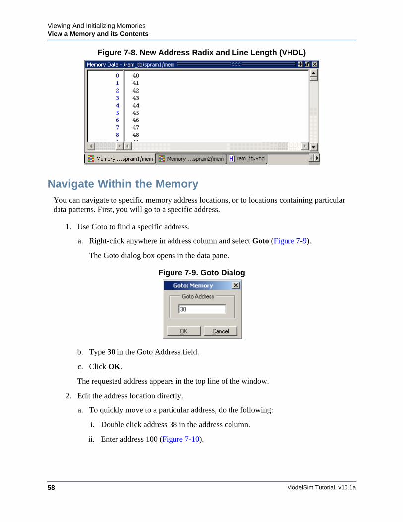
Figure 7-8. New Address Radix and Line Length (VHDL)
Navigate Within the MemoryYou can navigate to specific memory address locations, or to locations containing particular data patterns. First, you will go to a specific address.
1. Use Goto to find a specific address.
a. Right-click anywhere in address column and select Goto (Figure 7-9).
The Goto dialog box opens in the data pane.
Figure 7-9. Goto Dialog
b. Type 30 in the Goto Address field.
c. Click OK.
The requested address appears in the top line of the window.
2. Edit the address location directly.
a. To quickly move to a particular address, do the following:
i. Double click address 38 in the address column.
ii. Enter address 100 (Figure 7-10).
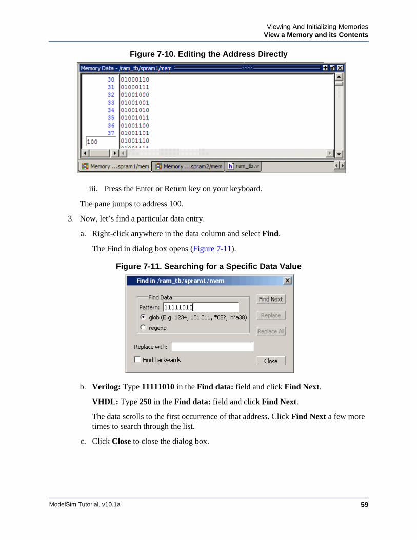
Viewing And Initializing MemoriesView a Memory and its Contents
ModelSim Tutorial, v10.1a 59
Figure 7-10. Editing the Address Directly
iii. Press the Enter or Return key on your keyboard.
The pane jumps to address 100.
3. Now, let’s find a particular data entry.
a. Right-click anywhere in the data column and select Find.
The Find in dialog box opens (Figure 7-11).
Figure 7-11. Searching for a Specific Data Value
b. Verilog: Type 11111010 in the Find data: field and click Find Next.
VHDL: Type 250 in the Find data: field and click Find Next.
The data scrolls to the first occurrence of that address. Click Find Next a few more times to search through the list.
c. Click Close to close the dialog box.
ModelSim Tutorial, v10.1a60
Viewing And Initializing MemoriesExport Memory Data to a File
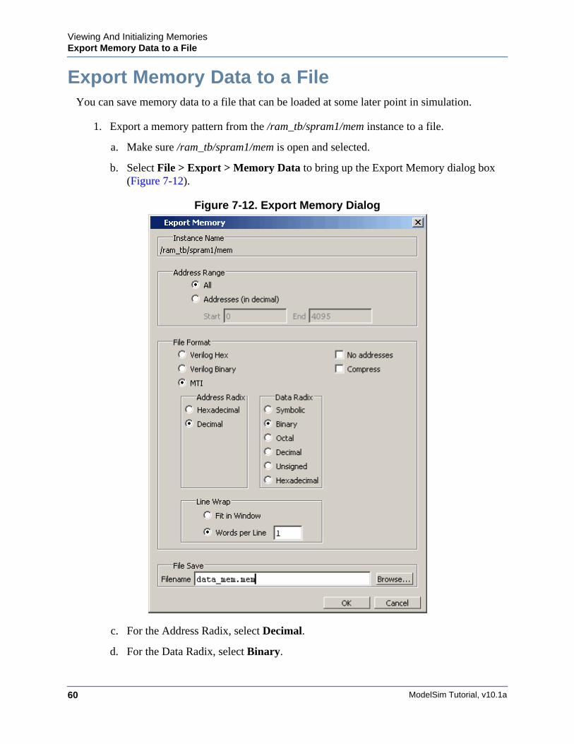
Export Memory Data to a FileYou can save memory data to a file that can be loaded at some later point in simulation.
1. Export a memory pattern from the /ram_tb/spram1/mem instance to a file.
a. Make sure /ram_tb/spram1/mem is open and selected.
b. Select File > Export > Memory Data to bring up the Export Memory dialog box (Figure 7-12).
Figure 7-12. Export Memory Dialog
c. For the Address Radix, select Decimal.
d. For the Data Radix, select Binary.
Viewing And Initializing MemoriesInitialize a Memory
ModelSim Tutorial, v10.1a 61
e. For the Words per Line, set to 1.
f. Type data_mem.mem into the Filename field.
g. Click OK.
You can view the exported file in any editor.
Memory pattern files can be exported as relocatable files, simply by leaving out the address information. Relocatable memory files can be loaded anywhere in a memory because no addresses are specified.
2. Export a relocatable memory pattern file from the /ram_tb/spram2/mem instance.
a. Select the Memory Data window for the /ram_tb/spram2/mem instance.
b. Right-click on the memory contents to open a popup menu and select Properties.
c. In the Properties dialog, set the Address Radix to Decimal; the Data Radix to Binary; and the Line Wrap to 1 Words per Line. Click OK to accept the changes and close the dialog.
d. Select File > Export > Memory Data to bring up the Export Memory dialog box.
e. For the Address Range, specify a Start address of 0 and End address of 250.
f. For the File Format, select MTI and No addresses to create a memory pattern that you can use to relocate somewhere else in the memory, or in another memory.
g. For Address Radix select Decimal, and for Data Radix select Binary.
h. For the Words per Line, set to 1.
i. Enter the file name as reloc.mem, then click OK to save the memory contents and close the dialog. You will use this file for initialization in the next section.
Initialize a MemoryIn ModelSim, it is possible to initialize a memory using one of three methods: from an exported memory file, from a fill pattern, or from both.
First, let’s initialize a memory from a file only. You will use the one you exported previously, data_mem.mem.
1. View instance /ram_tb/spram3/mem.
a. Double-click the /ram_tb/spram3/mem instance in the Memories tab.
This will open a new Memory Data window to display the contents of /ram_tb/spram3/mem. Familiarize yourself with the contents so you can identify changes once the initialization is complete.
ModelSim Tutorial, v10.1a62
Viewing And Initializing MemoriesInitialize a Memory
b. Right-click and select Properties to bring up the Properties dialog.
c. Change the Address Radix to Decimal, Data Radix to Binary, Words per Line to 1, and click OK.
2. Initialize spram3 from a file.
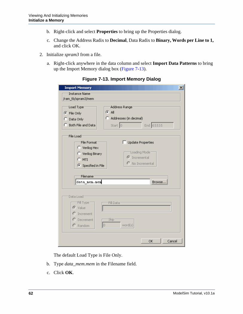
a. Right-click anywhere in the data column and select Import Data Patterns to bring up the Import Memory dialog box (Figure 7-13).
Figure 7-13. Import Memory Dialog
The default Load Type is File Only.
b. Type data_mem.mem in the Filename field.
c. Click OK.
Viewing And Initializing MemoriesInitialize a Memory
ModelSim Tutorial, v10.1a 63
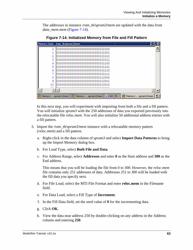
The addresses in instance /ram_tb/spram3/mem are updated with the data from data_mem.mem (Figure 7-14).
Figure 7-14. Initialized Memory from File and Fill Pattern
In this next step, you will experiment with importing from both a file and a fill pattern. You will initialize spram3 with the 250 addresses of data you exported previously into the relocatable file reloc.mem. You will also initialize 50 additional address entries with a fill pattern.
3. Import the /ram_tb/spram3/mem instance with a relocatable memory pattern (reloc.mem) and a fill pattern.
a. Right-click in the data column of spram3 and select Import Data Patterns to bring up the Import Memory dialog box.
b. For Load Type, select Both File and Data.
c. For Address Range, select Addresses and enter 0 as the Start address and 300 as the End address.
This means that you will be loading the file from 0 to 300. However, the reloc.mem file contains only 251 addresses of data. Addresses 251 to 300 will be loaded with the fill data you specify next.
d. For File Load, select the MTI File Format and enter reloc.mem in the Filename field.
e. For Data Load, select a Fill Type of Increment.
f. In the Fill Data field, set the seed value of 0 for the incrementing data.
g. Click OK.
h. View the data near address 250 by double-clicking on any address in the Address column and entering 250.
ModelSim Tutorial, v10.1a64
Viewing And Initializing MemoriesInteractive Debugging Commands
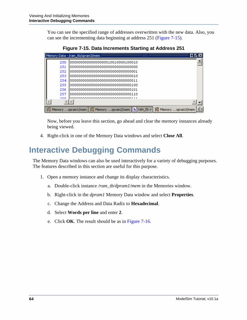
You can see the specified range of addresses overwritten with the new data. Also, you can see the incrementing data beginning at address 251 (Figure 7-15).
Figure 7-15. Data Increments Starting at Address 251
Now, before you leave this section, go ahead and clear the memory instances already being viewed.
4. Right-click in one of the Memory Data windows and select Close All.
Interactive Debugging CommandsThe Memory Data windows can also be used interactively for a variety of debugging purposes. The features described in this section are useful for this purpose.
1. Open a memory instance and change its display characteristics.
a. Double-click instance /ram_tb/dpram1/mem in the Memories window.
b. Right-click in the dpram1 Memory Data window and select Properties.
c. Change the Address and Data Radix to Hexadecimal.
d. Select Words per line and enter 2.
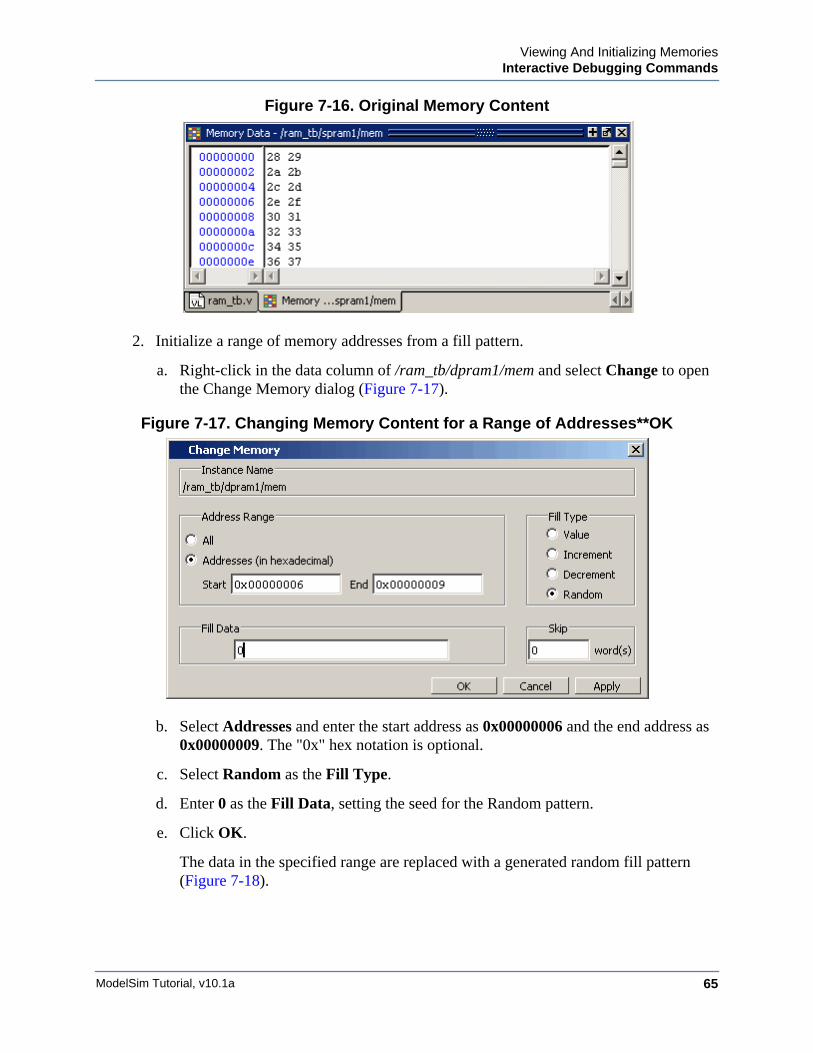
e. Click OK. The result should be as in Figure 7-16.
Viewing And Initializing MemoriesInteractive Debugging Commands
ModelSim Tutorial, v10.1a 65
Figure 7-16. Original Memory Content
2. Initialize a range of memory addresses from a fill pattern.
a. Right-click in the data column of /ram_tb/dpram1/mem and select Change to open the Change Memory dialog (Figure 7-17).
Figure 7-17. Changing Memory Content for a Range of Addresses**OK
b. Select Addresses and enter the start address as 0x00000006 and the end address as 0x00000009. The "0x" hex notation is optional.
c. Select Random as the Fill Type.
d. Enter 0 as the Fill Data, setting the seed for the Random pattern.
e. Click OK.
The data in the specified range are replaced with a generated random fill pattern (Figure 7-18).
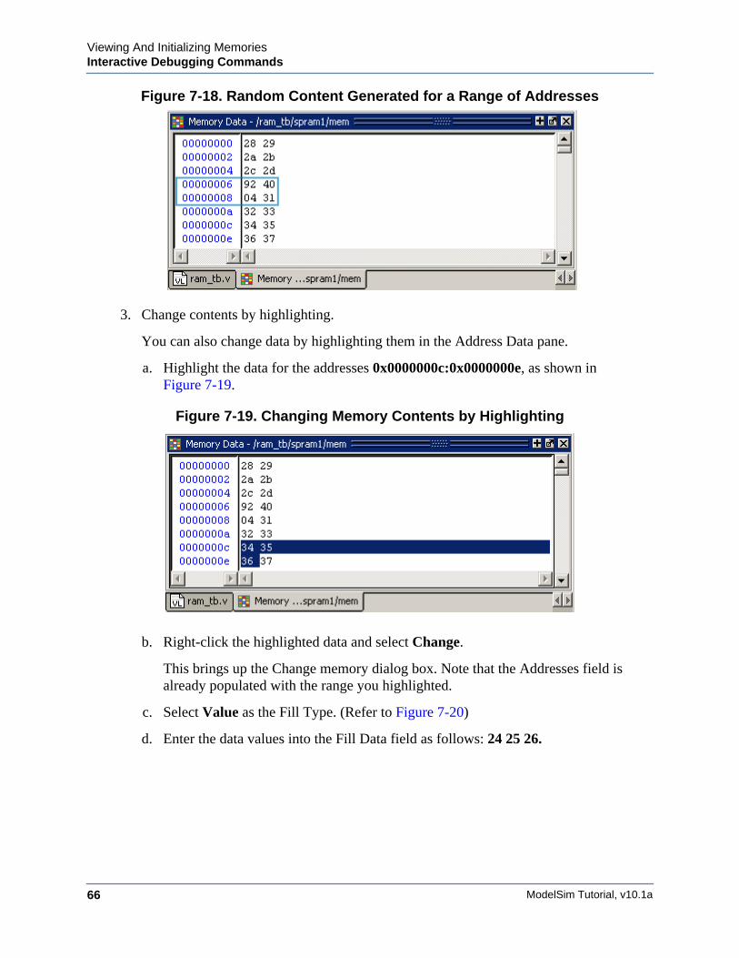
ModelSim Tutorial, v10.1a66
Viewing And Initializing MemoriesInteractive Debugging Commands
Figure 7-18. Random Content Generated for a Range of Addresses
3. Change contents by highlighting.
You can also change data by highlighting them in the Address Data pane.
a. Highlight the data for the addresses 0x0000000c:0x0000000e, as shown in Figure 7-19.
Figure 7-19. Changing Memory Contents by Highlighting
b. Right-click the highlighted data and select Change.
This brings up the Change memory dialog box. Note that the Addresses field is already populated with the range you highlighted.
c. Select Value as the Fill Type. (Refer to Figure 7-20)
d. Enter the data values into the Fill Data field as follows: 24 25 26.
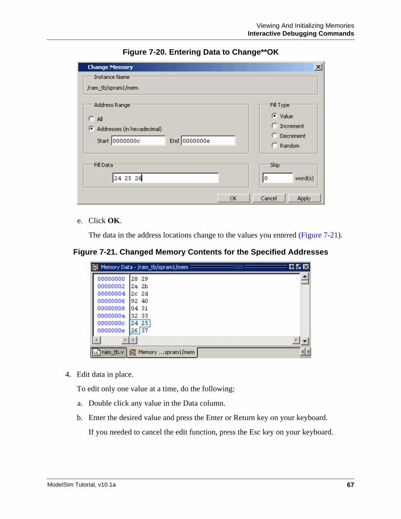
Viewing And Initializing MemoriesInteractive Debugging Commands
ModelSim Tutorial, v10.1a 67
Figure 7-20. Entering Data to Change**OK
e. Click OK.
The data in the address locations change to the values you entered (Figure 7-21).
Figure 7-21. Changed Memory Contents for the Specified Addresses
4. Edit data in place.
To edit only one value at a time, do the following:
a. Double click any value in the Data column.
b. Enter the desired value and press the Enter or Return key on your keyboard.
If you needed to cancel the edit function, press the Esc key on your keyboard.

ModelSim Tutorial, v10.1a68
Viewing And Initializing MemoriesInteractive Debugging Commands
Lesson Wrap-Up
This concludes this lesson. Before continuing we need to end the current simulation.
1. Select Simulate > End Simulation. Click Yes.
ModelSim Tutorial, v10.1a 69
Chapter 8Automating Simulation
Introduction
Aside from executing a couple of pre-existing DO files, the previous lessons focused on using ModelSim in interactive mode: executing single commands, one after another, via the GUI menus or Main window command line. In situations where you have repetitive tasks to complete, you can increase your productivity with DO files.
DO files are scripts that allow you to execute many commands at once. The scripts can be as simple as a series of ModelSim commands with associated arguments, or they can be full-blown Tcl programs with variables, conditional execution, and so forth. You can execute DO files from within the GUI or you can run them from the system command prompt without ever invoking the GUI.
NoteThis lesson assumes that you have added the <install_dir>/<platform> directory to your PATH. If you did not, you will need to specify full paths to the tools (i.e., vlib, vmap, vlog, vcom, and vsim) that are used in the lesson.
Related Reading
User’s Manual Chapter: Tcl and Macros (DO Files).
Practical Programming in Tcl and Tk, Brent B. Welch, Copyright 1997
Creating a Simple DO FileCreating a DO file is as simple as typing a set of commands in a text file. In this exercise, you will create a DO file that loads a design, adds signals to the Wave window, provides stimulus to those signals, and then advances the simulation. You can also create a DO file from a saved transcript file. Refer to "Saving a Transcript File as a Macro (DO file)."
1. Change to the directory you created in the "Basic Simulation" lesson.
2. Create a DO file that will add signals to the Wave window, force signals, and run the simulation.
a. Select File > New > Source > Do to create a new DO file.
b. Enter the following commands into the Source window:
vsim test_counter
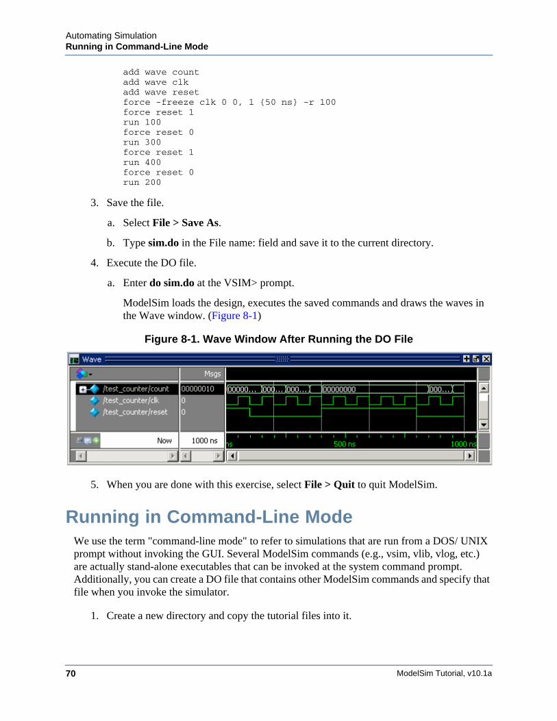
ModelSim Tutorial, v10.1a70
Automating SimulationRunning in Command-Line Mode
add wave countadd wave clkadd wave resetforce -freeze clk 0 0, 1 {50 ns} -r 100force reset 1run 100force reset 0run 300force reset 1run 400force reset 0run 200
3. Save the file.
a. Select File > Save As.
b. Type sim.do in the File name: field and save it to the current directory.
4. Execute the DO file.
a. Enter do sim.do at the VSIM> prompt.
ModelSim loads the design, executes the saved commands and draws the waves in the Wave window. (Figure 8-1)
Figure 8-1. Wave Window After Running the DO File
5. When you are done with this exercise, select File > Quit to quit ModelSim.
Running in Command-Line ModeWe use the term "command-line mode" to refer to simulations that are run from a DOS/ UNIX prompt without invoking the GUI. Several ModelSim commands (e.g., vsim, vlib, vlog, etc.) are actually stand-alone executables that can be invoked at the system command prompt. Additionally, you can create a DO file that contains other ModelSim commands and specify that file when you invoke the simulator.
1. Create a new directory and copy the tutorial files into it.
Automating SimulationRunning in Command-Line Mode
ModelSim Tutorial, v10.1a 71
Start by creating a new directory for this exercise. Create the directory and copy the following files into it:
• /<install_dir>/examples/tutorials/verilog/automation/counter.v
• /<install_dir>/examples/tutorials/verilog/automation/stim.do
This lesson uses the Verilog file counter.v. If you have a VHDL license, use the counter.vhd and stim.do files in the /<install_dir>/examples/tutorials/vhdl/automation directory instead.
2. Create a new design library and compile the source file.
Again, enter these commands at a DOS/ UNIX prompt in the new directory you created in step 1.
a. Type vlib work at the DOS/ UNIX prompt.
b. For Verilog, type vlog counter.v at the DOS/ UNIX prompt. For VHDL, type vcom counter.vhd.
3. Create a DO file.
a. Open a text editor.
b. Type the following lines into a new file:
# list all signals in decimal formatadd list -decimal *
# read in stimulusdo stim.do
# output resultswrite list counter.lst
# quit the simulationquit -f
c. Save the file with the name sim.do and place it in the current directory.
4. Run the batch-mode simulation.
a. Enter the following command at the DOS/UNIX prompt:
vsim -c -do sim.do counter -wlf counter.wlf
The -c argument instructs ModelSim not to invoke the GUI. The -wlf argument saves the simulation results in a WLF file. This allows you to view the simulation results in the GUI for debugging purposes.
5. View the list output.
a. Open counter.lst and view the simulation results. Output produced by the Verilog version of the design should look like the following:
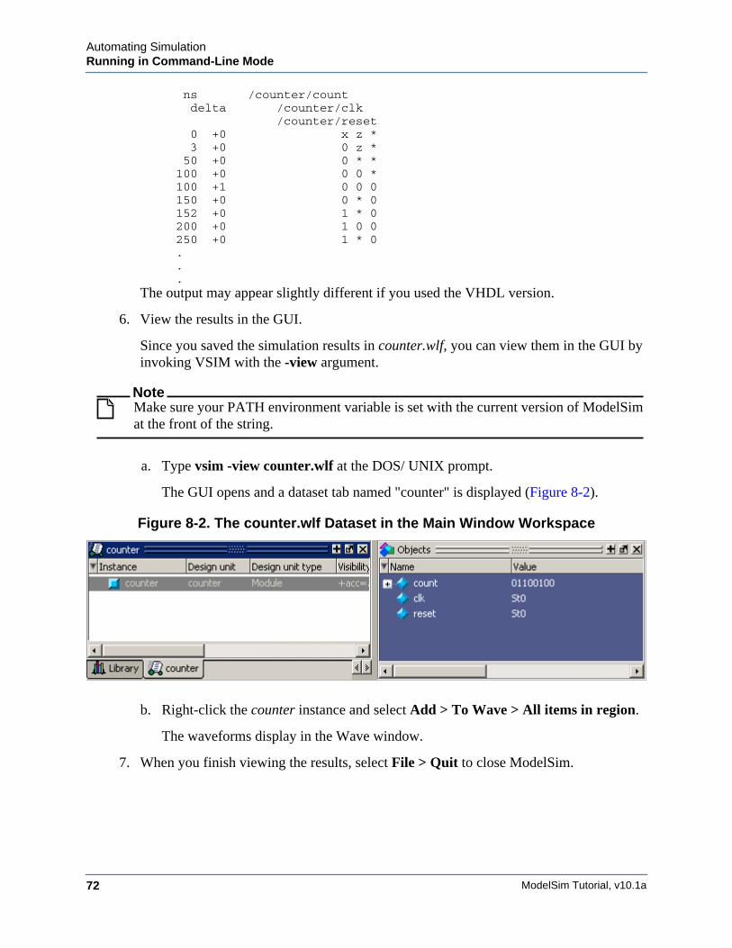
ModelSim Tutorial, v10.1a72
Automating SimulationRunning in Command-Line Mode
ns /counter/count delta /counter/clk /counter/reset 0 +0 x z * 3 +0 0 z * 50 +0 0 * * 100 +0 0 0 * 100 +1 0 0 0 150 +0 0 * 0 152 +0 1 * 0 200 +0 1 0 0 250 +0 1 * 0 . . .
The output may appear slightly different if you used the VHDL version.
6. View the results in the GUI.
Since you saved the simulation results in counter.wlf, you can view them in the GUI by invoking VSIM with the -view argument.
NoteMake sure your PATH environment variable is set with the current version of ModelSim at the front of the string.
a. Type vsim -view counter.wlf at the DOS/ UNIX prompt.
The GUI opens and a dataset tab named "counter" is displayed (Figure 8-2).
Figure 8-2. The counter.wlf Dataset in the Main Window Workspace
b. Right-click the counter instance and select Add > To Wave > All items in region.
The waveforms display in the Wave window.
7. When you finish viewing the results, select File > Quit to close ModelSim.
Automating SimulationUsing Tcl with the Simulator
ModelSim Tutorial, v10.1a 73
Using Tcl with the SimulatorThe DO files used in previous exercises contained only ModelSim commands. However, DO files are really just Tcl scripts. This means you can include a whole variety of Tcl constructs such as procedures, conditional operators, math and trig functions, regular expressions, and so forth.
In this exercise, you create a simple Tcl script that tests for certain values on a signal and then adds bookmarks that zoom the Wave window when that value exists. Bookmarks allow you to save a particular zoom range and scroll position in the Wave window.
1. Create the script.
a. In a text editor, open a new file and enter the following lines:
proc add_wave_zoom {stime num} { echo "Bookmarking wave $num" bookmark add wave "bk$num" "[expr $stime - 50] [expr $stime + 100]" 0}
These commands do the following:
• Create a new procedure called "add_wave_zoom" that has two arguments, stime and num.
• Create a bookmark with a zoom range from the current simulation time minus 50 time units to the current simulation time plus 100 time units.
b. Now add these lines to the bottom of the script:
add wave -r /*when {clk'event and clk="1"} { echo "Count is [exa count]" if {[examine count]== "00100111"} { add_wave_zoom $now 1 } elseif {[examine count]== "01000111"} { add_wave_zoom $now 2 }}
These commands do the following:
• Add all signals to the Wave window.
• Use a when statement to identify when clk transitions to 1.
• Examine the value of count at those transitions and add a bookmark if it is a certain value.
c. Save the script with the name "add_bkmrk.do" into the directory you created in the Basic Simulation lesson.
2. Load the test_counter design unit.
a. Start ModelSim.

ModelSim Tutorial, v10.1a74
Automating SimulationUsing Tcl with the Simulator
b. Select File > Change Directory and change to the directory you saved the DO file to in step 1c above.
c. Enter the following command at the QuestaSim> prompt:
vsim test_counter
3. Execute the DO file and run the design.
a. Type do add_bkmrk.do at the VSIM> prompt.
b. Type run 1500 ns at the VSIM> prompt.
The simulation runs and the DO file creates two bookmarks.
c. If the Wave window is docked in the Main window make it the active window (click anywhere in the Wave window), then select Wave > Bookmarks > bk1. If the window is undocked, select View > Bookmarks > bk1 in the Wave window.
Watch the Wave window zoom in and scroll to the time when count is 00100111. Try the bk2 bookmark as well.
Lesson Wrap-Up
This concludes this lesson.
1. Select File > Quit to close ModelSim.
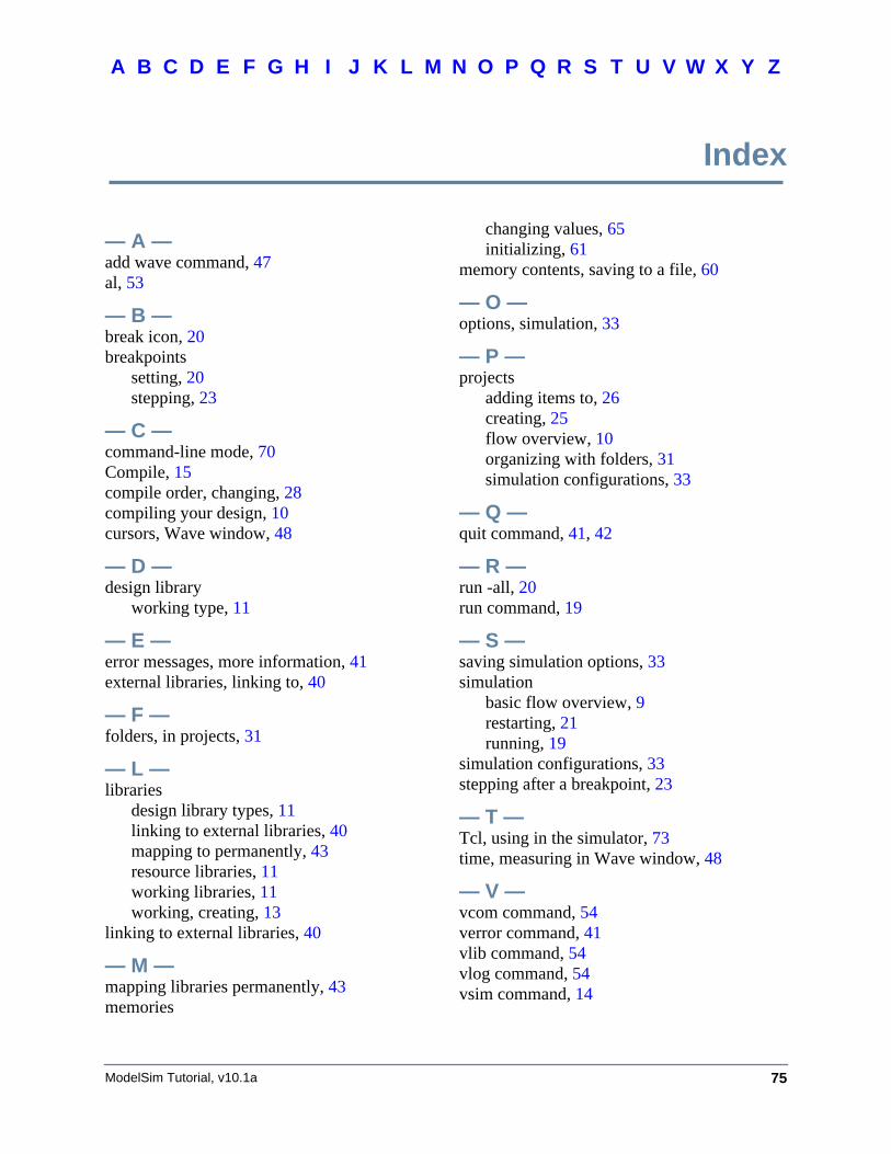
75
A B F GDC E H I J K L M N O P Q R S T U V XW Y Z
ModelSim Tutorial, v10.1a
Index
— A —add wave command, 47al, 53
— B —break icon, 20breakpoints
setting, 20stepping, 23
— C —command-line mode, 70Compile, 15compile order, changing, 28compiling your design, 10cursors, Wave window, 48
— D —design library
working type, 11
— E —error messages, more information, 41external libraries, linking to, 40
— F —folders, in projects, 31
— L —libraries
design library types, 11linking to external libraries, 40mapping to permanently, 43resource libraries, 11working libraries, 11working, creating, 13
linking to external libraries, 40
— M —mapping libraries permanently, 43memories
changing values, 65initializing, 61
memory contents, saving to a file, 60
— O —options, simulation, 33
— P —projects
adding items to, 26creating, 25flow overview, 10organizing with folders, 31simulation configurations, 33
— Q —quit command, 41, 42
— R —run -all, 20run command, 19
— S —saving simulation options, 33simulation
basic flow overview, 9restarting, 21running, 19
simulation configurations, 33stepping after a breakpoint, 23
— T —Tcl, using in the simulator, 73time, measuring in Wave window, 48
— V —vcom command, 54verror command, 41vlib command, 54vlog command, 54vsim command, 14
Index
76 ModelSim Tutorial, v10.1a
A B F GDC E H I J K L M N O P Q R S T U V XW Y Z
— W —Wave window
adding items to, 46cursors, 48measuring time with cursors, 48zooming, 47
working library, creating, 10, 13
— Z —zooming, Wave window, 47
End-User License AgreementThe latest version of the End-User License Agreement is available on-line at:
www.mentor.com/eula
END-USER LICENSE AGREEMENT (“Agreement”)
This is a legal agreement concerning the use of Software (as defined in Section 2) and hardware (collectively “Products”)between the company acquiring the Products (“Customer”), and the Mentor Graphics entity that issued thecorresponding quotation or, if no quotation was issued, the applicable local Mentor Graphics entity (“MentorGraphics”). Except for license agreements related to the subject matter of this license agreement which are physicallysigned by Customer and an authorized representative of Mentor Graphics, this Agreement and the applicable quotationcontain the parties' entire understanding relating to the subject matter and supersede all prior or contemporaneousagreements. If Customer does not agree to these terms and conditions, promptly return or, in the case of Softwarereceived electronically, certify destruction of Software and all accompanying items within five days after receipt ofSoftware and receive a full refund of any license fee paid.
1. ORDERS, FEES AND PAYMENT.
1.1. To the extent Customer (or if agreed by Mentor Graphics, Customer’s appointed third party buying agent) places andMentor Graphics accepts purchase orders pursuant to this Agreement (“Order(s)”), each Order will constitute a contractbetween Customer and Mentor Graphics, which shall be governed solely and exclusively by the terms and conditions ofthis Agreement, any applicable addenda and the applicable quotation, whether or not these documents are referenced on theOrder. Any additional or conflicting terms and conditions appearing on an Order will not be effective unless agreed inwriting by an authorized representative of Customer and Mentor Graphics.
1.2. Amounts invoiced will be paid, in the currency specified on the applicable invoice, within 30 days from the date of suchinvoice. Any past due invoices will be subject to the imposition of interest charges in the amount of one and one-halfpercent per month or the applicable legal rate currently in effect, whichever is lower. Prices do not include freight,insurance, customs duties, taxes or other similar charges, which Mentor Graphics will state separately in the applicableinvoice(s). Unless timely provided with a valid certificate of exemption or other evidence that items are not taxable, MentorGraphics will invoice Customer for all applicable taxes including, but not limited to, VAT, GST, sales tax and service tax.Customer will make all payments free and clear of, and without reduction for, any withholding or other taxes; any suchtaxes imposed on payments by Customer hereunder will be Customer’s sole responsibility. If Customer appoints a thirdparty to place purchase orders and/or make payments on Customer’s behalf, Customer shall be liable for payment underOrders placed by such third party in the event of default.
1.3. All Products are delivered FCA factory (Incoterms 2000), freight prepaid and invoiced to Customer, except Softwaredelivered electronically, which shall be deemed delivered when made available to Customer for download. MentorGraphics retains a security interest in all Products delivered under this Agreement, to secure payment of the purchase priceof such Products, and Customer agrees to sign any documents that Mentor Graphics determines to be necessary orconvenient for use in filing or perfecting such security interest. Mentor Graphics’ delivery of Software by electronic meansis subject to Customer’s provision of both a primary and an alternate e-mail address.
2. GRANT OF LICENSE. The software installed, downloaded, or otherwise acquired by Customer under this Agreement,including any updates, modifications, revisions, copies, documentation and design data (“Software”) are copyrighted, tradesecret and confidential information of Mentor Graphics or its licensors, who maintain exclusive title to all Software and retainall rights not expressly granted by this Agreement. Mentor Graphics grants to Customer, subject to payment of applicablelicense fees, a nontransferable, nonexclusive license to use Software solely: (a) in machine-readable, object-code form (exceptas provided in Subsection 5.2); (b) for Customer’s internal business purposes; (c) for the term of the license; and (d) on thecomputer hardware and at the site authorized by Mentor Graphics. A site is restricted to a one-half mile (800 meter) radius.Customer may have Software temporarily used by an employee for telecommuting purposes from locations other than aCustomer office, such as the employee's residence, an airport or hotel, provided that such employee's primary place ofemployment is the site where the Software is authorized for use. Mentor Graphics’ standard policies and programs, which varydepending on Software, license fees paid or services purchased, apply to the following: (a) relocation of Software; (b) use ofSoftware, which may be limited, for example, to execution of a single session by a single user on the authorized hardware or fora restricted period of time (such limitations may be technically implemented through the use of authorization codes or similardevices); and (c) support services provided, including eligibility to receive telephone support, updates, modifications, andrevisions. For the avoidance of doubt, if Customer requests any change or enhancement to Software, whether in the course ofreceiving support or consulting services, evaluating Software, performing beta testing or otherwise, any inventions, product
IMPORTANT INFORMATION
USE OF ALL SOFTWARE IS SUBJECT TO LICENSE RESTRICTIONS. CAREFULLY READ THIS LICENSE AGREEMENT BEFORE USING THE PRODUCTS. USE OF SOFTWARE INDICATES CUSTOMER’S
COMPLETE AND UNCONDITIONAL ACCEPTANCE OF THE TERMS AND CONDITIONS SET FORTH IN THIS AGREEMENT. ANY ADDITIONAL OR DIFFERENT PURCHASE ORDER TERMS AND CONDITIONS
SHALL NOT APPLY.
improvements, modifications or developments made by Mentor Graphics (at Mentor Graphics’ sole discretion) will be theexclusive property of Mentor Graphics.
3. ESC SOFTWARE. If Customer purchases a license to use development or prototyping tools of Mentor Graphics’ EmbeddedSoftware Channel (“ESC”), Mentor Graphics grants to Customer a nontransferable, nonexclusive license to reproduce anddistribute executable files created using ESC compilers, including the ESC run-time libraries distributed with ESC C and C++compiler Software that are linked into a composite program as an integral part of Customer’s compiled computer program,provided that Customer distributes these files only in conjunction with Customer’s compiled computer program. MentorGraphics does NOT grant Customer any right to duplicate, incorporate or embed copies of Mentor Graphics’ real-time operatingsystems or other embedded software products into Customer’s products or applications without first signing or otherwiseagreeing to a separate agreement with Mentor Graphics for such purpose.
4. BETA CODE.
4.1. Portions or all of certain Software may contain code for experimental testing and evaluation (“Beta Code”), which may notbe used without Mentor Graphics’ explicit authorization. Upon Mentor Graphics’ authorization, Mentor Graphics grants toCustomer a temporary, nontransferable, nonexclusive license for experimental use to test and evaluate the Beta Codewithout charge for a limited period of time specified by Mentor Graphics. This grant and Customer’s use of the Beta Codeshall not be construed as marketing or offering to sell a license to the Beta Code, which Mentor Graphics may choose not torelease commercially in any form.
4.2. If Mentor Graphics authorizes Customer to use the Beta Code, Customer agrees to evaluate and test the Beta Code undernormal conditions as directed by Mentor Graphics. Customer will contact Mentor Graphics periodically during Customer’suse of the Beta Code to discuss any malfunctions or suggested improvements. Upon completion of Customer’s evaluationand testing, Customer will send to Mentor Graphics a written evaluation of the Beta Code, including its strengths,weaknesses and recommended improvements.
4.3. Customer agrees to maintain Beta Code in confidence and shall restrict access to the Beta Code, including the methods andconcepts utilized therein, solely to those employees and Customer location(s) authorized by Mentor Graphics to performbeta testing. Customer agrees that any written evaluations and all inventions, product improvements, modifications ordevelopments that Mentor Graphics conceived or made during or subsequent to this Agreement, including those basedpartly or wholly on Customer’s feedback, will be the exclusive property of Mentor Graphics. Mentor Graphics will haveexclusive rights, title and interest in all such property. The provisions of this Subsection 4.3 shall survive termination ofthis Agreement.
5. RESTRICTIONS ON USE.
5.1. Customer may copy Software only as reasonably necessary to support the authorized use. Each copy must include allnotices and legends embedded in Software and affixed to its medium and container as received from Mentor Graphics. Allcopies shall remain the property of Mentor Graphics or its licensors. Customer shall maintain a record of the number andprimary location of all copies of Software, including copies merged with other software, and shall make those recordsavailable to Mentor Graphics upon request. Customer shall not make Products available in any form to any person otherthan Customer’s employees and on-site contractors, excluding Mentor Graphics competitors, whose job performancerequires access and who are under obligations of confidentiality. Customer shall take appropriate action to protect theconfidentiality of Products and ensure that any person permitted access does not disclose or use it except as permitted bythis Agreement. Customer shall give Mentor Graphics written notice of any unauthorized disclosure or use of the Productsas soon as Customer learns or becomes aware of such unauthorized disclosure or use. Except as otherwise permitted forpurposes of interoperability as specified by applicable and mandatory local law, Customer shall not reverse-assemble,reverse-compile, reverse-engineer or in any way derive any source code from Software. Log files, data files, rule files andscript files generated by or for the Software (collectively “Files”), including without limitation files containing StandardVerification Rule Format (“SVRF”) and Tcl Verification Format (“TVF”) which are Mentor Graphics’ proprietarysyntaxes for expressing process rules, constitute or include confidential information of Mentor Graphics. Customer mayshare Files with third parties, excluding Mentor Graphics competitors, provided that the confidentiality of such Files isprotected by written agreement at least as well as Customer protects other information of a similar nature or importance,but in any case with at least reasonable care. Customer may use Files containing SVRF or TVF only with Mentor Graphicsproducts. Under no circumstances shall Customer use Software or Files or allow their use for the purpose of developing,enhancing or marketing any product that is in any way competitive with Software, or disclose to any third party the resultsof, or information pertaining to, any benchmark.
5.2. If any Software or portions thereof are provided in source code form, Customer will use the source code only to correctsoftware errors and enhance or modify the Software for the authorized use. Customer shall not disclose or permit disclosureof source code, in whole or in part, including any of its methods or concepts, to anyone except Customer’s employees orcontractors, excluding Mentor Graphics competitors, with a need to know. Customer shall not copy or compile source codein any manner except to support this authorized use.
5.3. Customer may not assign this Agreement or the rights and duties under it, or relocate, sublicense or otherwise transfer theProducts, whether by operation of law or otherwise (“Attempted Transfer”), without Mentor Graphics’ prior writtenconsent and payment of Mentor Graphics’ then-current applicable relocation and/or transfer fees. Any Attempted Transferwithout Mentor Graphics’ prior written consent shall be a material breach of this Agreement and may, at Mentor Graphics’option, result in the immediate termination of the Agreement and/or the licenses granted under this Agreement. The termsof this Agreement, including without limitation the licensing and assignment provisions, shall be binding upon Customer’spermitted successors in interest and assigns.
5.4. The provisions of this Section 5 shall survive the termination of this Agreement.
6. SUPPORT SERVICES. To the extent Customer purchases support services, Mentor Graphics will provide Customer updatesand technical support for the Products, at the Customer site(s) for which support is purchased, in accordance with MentorGraphics’ then current End-User Support Terms located at http://supportnet.mentor.com/about/legal/.
7. AUTOMATIC CHECK FOR UPDATES; PRIVACY. Technological measures in Software may communicate with serversof Mentor Graphics or its contractors for the purpose of checking for and notifying the user of updates and to ensure that theSoftware in use is licensed in compliance with this Agreement. Mentor Graphics will not collect any personally identifiable datain this process and will not disclose any data collected to any third party without the prior written consent of Customer, except toMentor Graphics’ outside attorneys or as may be required by a court of competent jurisdiction.
8. LIMITED WARRANTY.
8.1. Mentor Graphics warrants that during the warranty period its standard, generally supported Products, when properlyinstalled, will substantially conform to the functional specifications set forth in the applicable user manual. MentorGraphics does not warrant that Products will meet Customer’s requirements or that operation of Products will beuninterrupted or error free. The warranty period is 90 days starting on the 15th day after delivery or upon installation,whichever first occurs. Customer must notify Mentor Graphics in writing of any nonconformity within the warranty period.For the avoidance of doubt, this warranty applies only to the initial shipment of Software under an Order and does notrenew or reset, for example, with the delivery of (a) Software updates or (b) authorization codes or alternate Software undera transaction involving Software re-mix. This warranty shall not be valid if Products have been subject to misuse,unauthorized modification or improper installation. MENTOR GRAPHICS’ ENTIRE LIABILITY AND CUSTOMER’SEXCLUSIVE REMEDY SHALL BE, AT MENTOR GRAPHICS’ OPTION, EITHER (A) REFUND OF THE PRICEPAID UPON RETURN OF THE PRODUCTS TO MENTOR GRAPHICS OR (B) MODIFICATION ORREPLACEMENT OF THE PRODUCTS THAT DO NOT MEET THIS LIMITED WARRANTY, PROVIDEDCUSTOMER HAS OTHERWISE COMPLIED WITH THIS AGREEMENT. MENTOR GRAPHICS MAKES NOWARRANTIES WITH RESPECT TO: (A) SERVICES; (B) PRODUCTS PROVIDED AT NO CHARGE; OR (C) BETACODE; ALL OF WHICH ARE PROVIDED “AS IS.”
8.2. THE WARRANTIES SET FORTH IN THIS SECTION 8 ARE EXCLUSIVE. NEITHER MENTOR GRAPHICS NORITS LICENSORS MAKE ANY OTHER WARRANTIES EXPRESS, IMPLIED OR STATUTORY, WITH RESPECT TOPRODUCTS PROVIDED UNDER THIS AGREEMENT. MENTOR GRAPHICS AND ITS LICENSORSSPECIFICALLY DISCLAIM ALL IMPLIED WARRANTIES OF MERCHANTABILITY, FITNESS FOR APARTICULAR PURPOSE AND NON-INFRINGEMENT OF INTELLECTUAL PROPERTY.
9. LIMITATION OF LIABILITY. EXCEPT WHERE THIS EXCLUSION OR RESTRICTION OF LIABILITY WOULD BEVOID OR INEFFECTIVE UNDER APPLICABLE LAW, IN NO EVENT SHALL MENTOR GRAPHICS OR ITSLICENSORS BE LIABLE FOR INDIRECT, SPECIAL, INCIDENTAL, OR CONSEQUENTIAL DAMAGES (INCLUDINGLOST PROFITS OR SAVINGS) WHETHER BASED ON CONTRACT, TORT OR ANY OTHER LEGAL THEORY, EVENIF MENTOR GRAPHICS OR ITS LICENSORS HAVE BEEN ADVISED OF THE POSSIBILITY OF SUCH DAMAGES. INNO EVENT SHALL MENTOR GRAPHICS’ OR ITS LICENSORS’ LIABILITY UNDER THIS AGREEMENT EXCEEDTHE AMOUNT RECEIVED FROM CUSTOMER FOR THE HARDWARE, SOFTWARE LICENSE OR SERVICE GIVINGRISE TO THE CLAIM. IN THE CASE WHERE NO AMOUNT WAS PAID, MENTOR GRAPHICS AND ITS LICENSORSSHALL HAVE NO LIABILITY FOR ANY DAMAGES WHATSOEVER. THE PROVISIONS OF THIS SECTION 9 SHALLSURVIVE THE TERMINATION OF THIS AGREEMENT.
10. HAZARDOUS APPLICATIONS. CUSTOMER ACKNOWLEDGES IT IS SOLELY RESPONSIBLE FOR TESTING ITSPRODUCTS USED IN APPLICATIONS WHERE THE FAILURE OR INACCURACY OF ITS PRODUCTS MIGHTRESULT IN DEATH OR PERSONAL INJURY (“HAZARDOUS APPLICATIONS”). NEITHER MENTOR GRAPHICSNOR ITS LICENSORS SHALL BE LIABLE FOR ANY DAMAGES RESULTING FROM OR IN CONNECTION WITHTHE USE OF MENTOR GRAPHICS PRODUCTS IN OR FOR HAZARDOUS APPLICATIONS. THE PROVISIONS OFTHIS SECTION 10 SHALL SURVIVE THE TERMINATION OF THIS AGREEMENT.
11. INDEMNIFICATION. CUSTOMER AGREES TO INDEMNIFY AND HOLD HARMLESS MENTOR GRAPHICS ANDITS LICENSORS FROM ANY CLAIMS, LOSS, COST, DAMAGE, EXPENSE OR LIABILITY, INCLUDINGATTORNEYS’ FEES, ARISING OUT OF OR IN CONNECTION WITH THE USE OF PRODUCTS AS DESCRIBED INSECTION 10. THE PROVISIONS OF THIS SECTION 11 SHALL SURVIVE THE TERMINATION OF THISAGREEMENT.
12. INFRINGEMENT.
12.1. Mentor Graphics will defend or settle, at its option and expense, any action brought against Customer in the United States,Canada, Japan, or member state of the European Union which alleges that any standard, generally supported Productacquired by Customer hereunder infringes a patent or copyright or misappropriates a trade secret in such jurisdiction.Mentor Graphics will pay costs and damages finally awarded against Customer that are attributable to the action. Customerunderstands and agrees that as conditions to Mentor Graphics’ obligations under this section Customer must: (a) notifyMentor Graphics promptly in writing of the action; (b) provide Mentor Graphics all reasonable information and assistanceto settle or defend the action; and (c) grant Mentor Graphics sole authority and control of the defense or settlement of theaction.

12.2. If a claim is made under Subsection 12.1 Mentor Graphics may, at its option and expense, (a) replace or modify the Productso that it becomes noninfringing; (b) procure for Customer the right to continue using the Product; or (c) require the returnof the Product and refund to Customer any purchase price or license fee paid, less a reasonable allowance for use.
12.3. Mentor Graphics has no liability to Customer if the action is based upon: (a) the combination of Software or hardware withany product not furnished by Mentor Graphics; (b) the modification of the Product other than by Mentor Graphics; (c) theuse of other than a current unaltered release of Software; (d) the use of the Product as part of an infringing process; (e) aproduct that Customer makes, uses, or sells; (f) any Beta Code or Product provided at no charge; (g) any software providedby Mentor Graphics’ licensors who do not provide such indemnification to Mentor Graphics’ customers; or(h) infringement by Customer that is deemed willful. In the case of (h), Customer shall reimburse Mentor Graphics for itsreasonable attorney fees and other costs related to the action.
12.4. THIS SECTION 12 IS SUBJECT TO SECTION 9 ABOVE AND STATES THE ENTIRE LIABILITY OF MENTORGRAPHICS AND ITS LICENSORS FOR DEFENSE, SETTLEMENT AND DAMAGES, AND CUSTOMER’S SOLEAND EXCLUSIVE REMEDY, WITH RESPECT TO ANY ALLEGED PATENT OR COPYRIGHT INFRINGEMENTOR TRADE SECRET MISAPPROPRIATION BY ANY PRODUCT PROVIDED UNDER THIS AGREEMENT.
13. TERMINATION AND EFFECT OF TERMINATION. If a Software license was provided for limited term use, such licensewill automatically terminate at the end of the authorized term.
13.1. Mentor Graphics may terminate this Agreement and/or any license granted under this Agreement immediately upon writtennotice if Customer: (a) exceeds the scope of the license or otherwise fails to comply with the licensing or confidentialityprovisions of this Agreement, or (b) becomes insolvent, files a bankruptcy petition, institutes proceedings for liquidation orwinding up or enters into an agreement to assign its assets for the benefit of creditors. For any other material breach of anyprovision of this Agreement, Mentor Graphics may terminate this Agreement and/or any license granted under thisAgreement upon 30 days written notice if Customer fails to cure the breach within the 30 day notice period. Termination ofthis Agreement or any license granted hereunder will not affect Customer’s obligation to pay for Products shipped orlicenses granted prior to the termination, which amounts shall be payable immediately upon the date of termination.
13.2. Upon termination of this Agreement, the rights and obligations of the parties shall cease except as expressly set forth in thisAgreement. Upon termination, Customer shall ensure that all use of the affected Products ceases, and shall return hardwareand either return to Mentor Graphics or destroy Software in Customer’s possession, including all copies anddocumentation, and certify in writing to Mentor Graphics within ten business days of the termination date that Customer nolonger possesses any of the affected Products or copies of Software in any form.
14. EXPORT. The Products provided hereunder are subject to regulation by local laws and United States government agencies,which prohibit export or diversion of certain products and information about the products to certain countries and certainpersons. Customer agrees that it will not export Products in any manner without first obtaining all necessary approval fromappropriate local and United States government agencies.
15. U.S. GOVERNMENT LICENSE RIGHTS. Software was developed entirely at private expense. All Software is commercialcomputer software within the meaning of the applicable acquisition regulations. Accordingly, pursuant to US FAR 48 CFR12.212 and DFAR 48 CFR 227.7202, use, duplication and disclosure of the Software by or for the U.S. Government or a U.S.Government subcontractor is subject solely to the terms and conditions set forth in this Agreement, except for provisions whichare contrary to applicable mandatory federal laws.
16. THIRD PARTY BENEFICIARY. Mentor Graphics Corporation, Mentor Graphics (Ireland) Limited, Microsoft Corporationand other licensors may be third party beneficiaries of this Agreement with the right to enforce the obligations set forth herein.
17. REVIEW OF LICENSE USAGE. Customer will monitor the access to and use of Software. With prior written notice andduring Customer’s normal business hours, Mentor Graphics may engage an internationally recognized accounting firm toreview Customer’s software monitoring system and records deemed relevant by the internationally recognized accounting firmto confirm Customer’s compliance with the terms of this Agreement or U.S. or other local export laws. Such review may includeFLEXlm or FLEXnet (or successor product) report log files that Customer shall capture and provide at Mentor Graphics’request. Customer shall make records available in electronic format and shall fully cooperate with data gathering to support thelicense review. Mentor Graphics shall bear the expense of any such review unless a material non-compliance is revealed. MentorGraphics shall treat as confidential information all information gained as a result of any request or review and shall only use ordisclose such information as required by law or to enforce its rights under this Agreement. The provisions of this Section 17shall survive the termination of this Agreement.
18. CONTROLLING LAW, JURISDICTION AND DISPUTE RESOLUTION. The owners of certain Mentor Graphicsintellectual property licensed under this Agreement are located in Ireland and the United States. To promote consistency aroundthe world, disputes shall be resolved as follows: excluding conflict of laws rules, this Agreement shall be governed by andconstrued under the laws of the State of Oregon, USA, if Customer is located in North or South America, and the laws of Irelandif Customer is located outside of North or South America. All disputes arising out of or in relation to this Agreement shall besubmitted to the exclusive jurisdiction of the courts of Portland, Oregon when the laws of Oregon apply, or Dublin, Ireland whenthe laws of Ireland apply. Notwithstanding the foregoing, all disputes in Asia arising out of or in relation to this Agreement shallbe resolved by arbitration in Singapore before a single arbitrator to be appointed by the chairman of the Singapore InternationalArbitration Centre (“SIAC”) to be conducted in the English language, in accordance with the Arbitration Rules of the SIAC ineffect at the time of the dispute, which rules are deemed to be incorporated by reference in this section. This section shall not

restrict Mentor Graphics’ right to bring an action against Customer in the jurisdiction where Customer’s place of business islocated. The United Nations Convention on Contracts for the International Sale of Goods does not apply to this Agreement.
19. SEVERABILITY. If any provision of this Agreement is held by a court of competent jurisdiction to be void, invalid,unenforceable or illegal, such provision shall be severed from this Agreement and the remaining provisions will remain in fullforce and effect.
20. MISCELLANEOUS. This Agreement contains the parties’ entire understanding relating to its subject matter and supersedes allprior or contemporaneous agreements, including but not limited to any purchase order terms and conditions. Some Softwaremay contain code distributed under a third party license agreement that may provide additional rights to Customer. Please seethe applicable Software documentation for details. This Agreement may only be modified in writing by authorizedrepresentatives of the parties. Waiver of terms or excuse of breach must be in writing and shall not constitute subsequentconsent, waiver or excuse.
Rev. 100615, Part No. 246066