Embed Size (px)
Citation preview

Operation & Safety Manual
Models400RTS500RTS
3120828November 9, 2007


FOREWORD
FOREWORD
This manual is a very important tool! Keep it with the machine at all times.
The purpose of this manual is to provide owners, users, operators, lessors, and lessees with the precautionsand operating procedures essential for the safe and proper machine operation for its intended purpose. It isimportant to stress proper machine usage at all times. All information in this manual must be read and under-stood before any attempt is made to operate the machine.
Because the manufacturer has no direct control over machine operation and application, proper safety prac-tices are the responsibility of the owners, users, operators, lessors, and lessees.
All instructions in this manual are based upon the use of the machine under proper operating conditions, withno deviations from the original design. Any alteration or modification of the machine is strictly forbidden withoutwritten approval from JLG Industries, Inc.
Due to continuous product improvements, JLG Industries, Inc. reserves the right to make specification changeswithout prior notification. Contact JLG Industries, Inc. for updated information.
Other Publications Available:
Service and Maintenance Manual ....................................................... 3120829
Illustrated Parts Manual ....................................................................... 3120830
3120828 – JLG Sizzor – a

FOREWORD
SAFETY ALERT SYMBOLS AND SAFETY SIGNAL WORDS
This is the Safety Alert Symbol. It is used to alert you to thepotential personal injury hazards. Obey all safety messagesthat follow this symbol to avoid possible injury or death
The Safety Alert Symbol will be used with the appropriate Safety Signal Word of “DANGER” “WARNING” or “CAUTION” toa potential hazard and designate a level of seriousness. The Safety Signal Words are inserted throughout this manual inBlack/White. On the machine, the Safety Signal Words will have either a Red, Orange, or Yellow background as part of asafety sign or decal. The “DANGER”, “WARNING”, and “CAUTION” Safety Signal Words, definitions, and associated colorsare as follows:
INDICATES AN IMMINENTLY HAZARDOUS SITUATION WHICH, IFNOT AVOIDED, WILL RESULT IN SERIOUS INJURY OR DEATH. THISSIGNAL WORD IS USED IN THE MOST EXTREME CASES. WHENINSTALLED ON THE MACHINE, THIS SIGNAL WORD WILL HAVE ARED BACKGROUND AS PART OF A DECAL.
INDICATES A POTENTIALITY HAZARDOUS SITUATION WHICH, IFNOT AVOIDED, COULD RESULT IN SERIOUS INJURY OR DEATH.WHEN INSTALLED ON THE MACHINE, THIS SIGNAL WORD WILLHAVE AN ORANGE BACKGROUND AS PART OF A DECAL.
INDICATES A POTENTIALITY HAZARDOUS SITUATION WHICH IFNOT AVOIDED, MAY RESULT IN MINOR OR MODERATE INJURY. ITMAY ALSO BE USED TO ALERT AGAINST UNSAFE PRACTICES.WHEN INSTALLED ON THE MACHINE, THIS SIGNAL WORD WILLHAVE A YELLOW BACKGROUND AS PART OF A DECAL.
INDICATES PROCEDURES ESSENTIAL FOR SAFE OPERATION ANDWHICH, IF NOT FOLLOWED, MAY RESULT IN A MACHINE MAL-FUNCTIONED DAMAGE. WHEN INSTALLED IN A MACHINE, THISSIGNAL WORD WILL HAVE A GREEN BACKGROUND AS PART OF ADECAL.
The “IMPORTANT” Safety Signal Word may also appear in this manual or on the machine. This Safety Signal Word typicallywill not appear with the Safety Alert Symbol, but contains important information that must be followed for safe and properoperation, The “IMPORTANT” Safety Signal Word definition and associated color is as follows.
b – JLG Sizzor – 3120828

FOREWORD
ALL SAFETY-RELATED BULLETINS MUST BE ACCOMPLISHED ON THIS PRODUCT. JLG INDUSTRIES, INC. MAY HAVE ISSUED SAFETY-RELATED BULLETINS FOR THIS JLG PRODUCT. CONTACT JLG INDUSTRIES, INC. OR THE LOCAL AUTHORIZED JLG DEALER FORINFORMATION REGARDING SAFETY-RELATED BULLETINS WHICH MAY HAVE BEEN ISSUED FOR THIS PRODUCT.
FOR THE PURPOSE OF RECEIVING SAFETY-RELATED BULLETINS, IT IS IMPORTANT THAT THE CURRENT OWNER OF THIS UNITENSURES JLG INDUSTRIES, INC. HAS UPDATED OWNERSHIP INFORMATION. CONTACT JLG INDUSTRIES, INC. TO ENSURE THAT THECURRENT OWNER RECORDS ARE UPDATED AND ACCURATE.
JLG INDUSTRIES, INC. MUST BE NOTIFIED IMMEDIATELY IN ALL INSTANCES WHERE JLG PRODUCTS HAVE BEEN INVOLVED IN ANACCIDENT INVOLVING BODILY INJURY OR DEATH OF PERSONNEL OR WHEN SUBSTANTIAL DAMAGE HAS OCCURRED TO PERSONALPROPERTY OR THE JLG PRODUCT.
FOR :
•Accident Reporting
•Product Safety Publications
•Current Owner Updates
•Questions Regarding Product Safety
•Standards and Regulations Compliance Information
•Questions Regarding Special Product Applications
•Questions Regarding Product Modifications
CONTACT :
Product Safety and Reliability DepartmentJLG Industries, Inc.1 JLG DriveMcConnellsburg, PA 17233
Toll Free: 877-JLG-SAFE877-554-7233
E-mail: [email protected]
3120828 – JLG Sizzor – c
FOREWORD
REVISION LOGOriginal Issue - March 1 1993Revised - August 24, 1999Revised - August 20, 2002Revised - December 5, 2002Revised - March 19, 2004Added Manual Part Number to Foreword - August 1, 2004Revised - August 19, 2004Revised - September 26, 2007Revised - November 9, 2007
d – JLG Sizzor – 3120828

TABLE OF CONTENTS
TABLE OF CONTENTS
SUBJECT - SECTION, PARAGRAPH PAGE NO.
TABLE OF CONTENTS
SECTION - FOREWORD
SECTION 1 - SAFETY PRECAUTIONS
1.1 General . . . . . . . . . . . . . . . . . . . . . . . . . . . . . . . . . . . . . . . . . . . . . . . . . . . . . . . . . . . . . . . . . . . . . .1-11.2 Pre-Operation . . . . . . . . . . . . . . . . . . . . . . . . . . . . . . . . . . . . . . . . . . . . . . . . . . . . . . . . . . . . . . . . .1-11.3 Operation. . . . . . . . . . . . . . . . . . . . . . . . . . . . . . . . . . . . . . . . . . . . . . . . . . . . . . . . . . . . . . . . . . . . .1-21.4 Towing, Lifting, and Hauling . . . . . . . . . . . . . . . . . . . . . . . . . . . . . . . . . . . . . . . . . . . . . . . . . . . . . .1-41.5 Maintenance . . . . . . . . . . . . . . . . . . . . . . . . . . . . . . . . . . . . . . . . . . . . . . . . . . . . . . . . . . . . . . . . . .1-5
SECTION 2 - MACHINE PREPARATION AND INSPECTION
2.1 General . . . . . . . . . . . . . . . . . . . . . . . . . . . . . . . . . . . . . . . . . . . . . . . . . . . . . . . . . . . . . . . . . . . . . .2-12.2 Preparation For Use . . . . . . . . . . . . . . . . . . . . . . . . . . . . . . . . . . . . . . . . . . . . . . . . . . . . . . . . . . . .2-12.3 Delivery and Periodic Inspection . . . . . . . . . . . . . . . . . . . . . . . . . . . . . . . . . . . . . . . . . . . . . . . . . .2-12.4 Daily Walk-Around Inspection. . . . . . . . . . . . . . . . . . . . . . . . . . . . . . . . . . . . . . . . . . . . . . . . . . . . .2-22.5 Daily Functional Check . . . . . . . . . . . . . . . . . . . . . . . . . . . . . . . . . . . . . . . . . . . . . . . . . . . . . . . . . .2-32.6 Lockout Cylinder Check (If Equipped) . . . . . . . . . . . . . . . . . . . . . . . . . . . . . . . . . . . . . . . . . . . . . .2-72.7 Dual Fuel System . . . . . . . . . . . . . . . . . . . . . . . . . . . . . . . . . . . . . . . . . . . . . . . . . . . . . . . . . . . . . .2-72.8 Torque Requirements . . . . . . . . . . . . . . . . . . . . . . . . . . . . . . . . . . . . . . . . . . . . . . . . . . . . . . . . . . .2-7
SECTION 3 - USER RESPONSIBILITIES AND MACHINE CONTROL
3.1 General . . . . . . . . . . . . . . . . . . . . . . . . . . . . . . . . . . . . . . . . . . . . . . . . . . . . . . . . . . . . . . . . . . . . . .3-13.2 Personnel Training . . . . . . . . . . . . . . . . . . . . . . . . . . . . . . . . . . . . . . . . . . . . . . . . . . . . . . . . . . . . .3-13.3 Operating Characteristics and Limitations . . . . . . . . . . . . . . . . . . . . . . . . . . . . . . . . . . . . . . . . . . .3-13.4 Controls and Indicators . . . . . . . . . . . . . . . . . . . . . . . . . . . . . . . . . . . . . . . . . . . . . . . . . . . . . . . . . .3-2
SECTION 4 - MACHINE OPERATION
4.1 Description . . . . . . . . . . . . . . . . . . . . . . . . . . . . . . . . . . . . . . . . . . . . . . . . . . . . . . . . . . . . . . . . . . .4-14.2 General . . . . . . . . . . . . . . . . . . . . . . . . . . . . . . . . . . . . . . . . . . . . . . . . . . . . . . . . . . . . . . . . . . . . . .4-24.3 Engine Operation . . . . . . . . . . . . . . . . . . . . . . . . . . . . . . . . . . . . . . . . . . . . . . . . . . . . . . . . . . . . . .4-24.4 Raising and Lowering (Lifting) . . . . . . . . . . . . . . . . . . . . . . . . . . . . . . . . . . . . . . . . . . . . . . . . . . . .4-34.5 Traversing Platform (Optional) . . . . . . . . . . . . . . . . . . . . . . . . . . . . . . . . . . . . . . . . . . . . . . . . . . . .4-34.6 Steering . . . . . . . . . . . . . . . . . . . . . . . . . . . . . . . . . . . . . . . . . . . . . . . . . . . . . . . . . . . . . . . . . . . . . .4-34.7 Traveling (Driving) . . . . . . . . . . . . . . . . . . . . . . . . . . . . . . . . . . . . . . . . . . . . . . . . . . . . . . . . . . . . . .4-34.8 Parking and Stowing . . . . . . . . . . . . . . . . . . . . . . . . . . . . . . . . . . . . . . . . . . . . . . . . . . . . . . . . . . . .4-54.9 Platform Loading . . . . . . . . . . . . . . . . . . . . . . . . . . . . . . . . . . . . . . . . . . . . . . . . . . . . . . . . . . . . . . .4-54.10 Safety Props . . . . . . . . . . . . . . . . . . . . . . . . . . . . . . . . . . . . . . . . . . . . . . . . . . . . . . . . . . . . . . . . . .4-54.11 Machine Tie Down. . . . . . . . . . . . . . . . . . . . . . . . . . . . . . . . . . . . . . . . . . . . . . . . . . . . . . . . . . . . . .4-64.12 Towing . . . . . . . . . . . . . . . . . . . . . . . . . . . . . . . . . . . . . . . . . . . . . . . . . . . . . . . . . . . . . . . . . . . . . . .4-6
SECTION 5 - EMERGENCY PROCEDURES
5.1 General . . . . . . . . . . . . . . . . . . . . . . . . . . . . . . . . . . . . . . . . . . . . . . . . . . . . . . . . . . . . . . . . . . . . . .5-15.2 Emergency Towing Procedures . . . . . . . . . . . . . . . . . . . . . . . . . . . . . . . . . . . . . . . . . . . . . . . . . . .5-15.3 Emergency Controls and Their Locations . . . . . . . . . . . . . . . . . . . . . . . . . . . . . . . . . . . . . . . . . . .5-15.4 Emergency Operation . . . . . . . . . . . . . . . . . . . . . . . . . . . . . . . . . . . . . . . . . . . . . . . . . . . . . . . . . . .5-25.5 Incident Notification. . . . . . . . . . . . . . . . . . . . . . . . . . . . . . . . . . . . . . . . . . . . . . . . . . . . . . . . . . . . .5-3
SECTION 6 - INSPECTION AND REPAIR LOG
3120828 – JLG Sizzor – i
TABLE OF CONTENTS (Continued)
LIST OF FIGURES
FIGURE NO. TITLE PAGE NO.
2-1. Daily Walk-Around Inspection Diagram . . . . . . . . . . . . . . . . . . . . . . . . . . . . . . . . . . . . . . . . . . . . .2-42-2. Walk-Around Inspection Points (Sheet 1 of 2) . . . . . . . . . . . . . . . . . . . . . . . . . . . . . . . . . . . . . . . .2-52-3. Walk-Around Inspection Points (Sheet 2 of 2) . . . . . . . . . . . . . . . . . . . . . . . . . . . . . . . . . . . . . . . .2-62-4. Lubrication Diagram . . . . . . . . . . . . . . . . . . . . . . . . . . . . . . . . . . . . . . . . . . . . . . . . . . . . . . . . . . . .2-82-5. Torque Chart . . . . . . . . . . . . . . . . . . . . . . . . . . . . . . . . . . . . . . . . . . . . . . . . . . . . . . . . . . . . . . . . . .2-103-1. Ground Control Station . . . . . . . . . . . . . . . . . . . . . . . . . . . . . . . . . . . . . . . . . . . . . . . . . . . . . . . . . .3-23-2. Platform Control Station . . . . . . . . . . . . . . . . . . . . . . . . . . . . . . . . . . . . . . . . . . . . . . . . . . . . . . . . .3-43-3. Decal Location. . . . . . . . . . . . . . . . . . . . . . . . . . . . . . . . . . . . . . . . . . . . . . . . . . . . . . . . . . . . . . . . .3-64-1. Grade and Sideslope . . . . . . . . . . . . . . . . . . . . . . . . . . . . . . . . . . . . . . . . . . . . . . . . . . . . . . . . . . .4-45-1. Drive Hub Disconnect . . . . . . . . . . . . . . . . . . . . . . . . . . . . . . . . . . . . . . . . . . . . . . . . . . . . . . . . . . .5-15-2. Drive Hub Connect . . . . . . . . . . . . . . . . . . . . . . . . . . . . . . . . . . . . . . . . . . . . . . . . . . . . . . . . . . . . .5-1
LIST OF TABLES
TABLE NO. TITLE PAGE NO.
1-1 Minimum Approach Distances (M.A.D.) . . . . . . . . . . . . . . . . . . . . . . . . . . . . . . . . . . . . . . . . . . . . .1-32-1 Lubrication Chart . . . . . . . . . . . . . . . . . . . . . . . . . . . . . . . . . . . . . . . . . . . . . . . . . . . . . . . . . . . . . . .2-93-1 Decal Location Legend . . . . . . . . . . . . . . . . . . . . . . . . . . . . . . . . . . . . . . . . . . . . . . . . . . . . . . . . . .3-74-1 Operating Specifications. . . . . . . . . . . . . . . . . . . . . . . . . . . . . . . . . . . . . . . . . . . . . . . . . . . . . . . . .4-26-1 Inspection and Repair Log . . . . . . . . . . . . . . . . . . . . . . . . . . . . . . . . . . . . . . . . . . . . . . . . . . . . . . .6-1
ii – JLG Sizzor – 3120828

SECTION 1 - SAFETY PRECAUTIONS
SECTION 1. SAFETY PRECAUTIONS
1.1 GENERAL
This section outlines the necessary precautions for properand safe machine usage and maintenance. In order topromote proper machine usage, it is mandatory that adaily routine is established based on the content of thismanual. A maintenance program, using the informationprovided in this manual and the Service and MaintenanceManual, must also be established by a qualified personand must be followed to ensure that the machine is safe tooperate.
The owner/user/operator/lessor/lessee of the machineshould not accept operating responsibility until this man-ual has been read, training is accomplished, and opera-tion of the machine has been completed under thesupervision of an experienced and qualified operator.
These sections contain the responsibilities of the owner,user, operator, lessor, and lessee concerning safety, train-ing, inspection, maintenance, application, and operation.Ifthere are any questions with regard to safety, training,inspection, maintenance, application, and operation,please contact JLG Industries, Inc. (“JLG”).
FAILURE TO COMPLY WITH THE SAFETY PRECAUTIONS LISTEDIN THIS MANUAL COULD RESULT IN MACHINE DAMAGE, PROP-ERTY DAMAGE, PERSONAL INJURY OR DEATH.
1.2 PRE-OPERATION
Operator Training and Knowledge
• The Operators and Safety Manual must be read in itsentirety before operating the machine. For clarification,questions, or additional information regarding any por-tions of this manual, contact JLG Industries, Inc.
• An operator must not accept operating responsibilitiesuntil adequate training has been given by competentand authorized persons.
• Allow only those authorized and qualified personnel tooperate the machine who have demonstrated that theyunderstand the safe and proper operation and mainte-nance of the unit.
• Read, understand, and obey all DANGERS, WARN-INGS, CAUTIONS, and operating instructions on themachine and in this manual.
• Ensure that the machine is to be used in a mannerwhich is within the scope of its intended application asdetermined by JLG.
• All operating personnel must be familiar with the emer-gency controls and emergency operation of themachine as specified in this manual.
• Read, understand, and obey all applicable employer,local, and governmental regulations as they pertain toyour utilization and application of the machine.
Workplace Inspection• Precautions to avoid all hazards in the work area must
be taken by the user before operation of the machine.
• Do not operate or raise the platform from a position ontrucks, trailers, railway cars, floating vessels, scaffoldsor other equipment unless the application is approvedin writing by JLG.
• Before operation, check work area for overhead haz-ards such as electric lines, bridge cranes, and otherpotential overhead obstructions.
• Check floor surfaces for holes, bumps, drop-offs,obstructions, debris, concealed holes, and otherpotential hazards.
• Check the work area for hazardous locations. Do notoperate the machine in hazardous environmentsunless approved for that purpose by JLG.
• Ensure that the ground conditions are adequate tosupport the maximum tire load indicated on the tireload decals located on the chassis adjacent to eachwheel.
• Do not operate the machine when wind conditionsexceed 28 mph (12.5 m/s).
• This machine can be operated in nominal ambient tem-peratures of 0o F to 104o F (-20o C to 40o C). ConsultJLG to optimize operation outside of this temperaturerange.
Machine Inspection • Do not operate this machine until the inspections and
functional checks have been performed as specified inSection 2 of this manual.
3120828 – JLG Lift – 1-1

SECTION 1 - SAFETY PRECAUTIONS
• Do not operate this machine until it has been servicedand maintained according to the maintenance andinspection requirements as specified in the machine’sService and Maintenance Manual.
• Ensure all safety devices are operating properly. Modi-fication of these devices is a safety violation.
MODIFICATION OR ALTERATION OF AN AERIAL WORK PLAT-FORM SHALL BE MADE ONLY WITH PRIOR WRITTEN PERMIS-SION FROM THE MANUFACTURER
• Do not operate any machine on which the safety orinstruction placards or decals are missing or illegible.
• Check the machine for modifications to original com-ponents. Ensure that any modifications have beenapproved by JLG.
• Avoid accumulation of debris on platform deck. Keepmud, oil, grease, and other slippery substances fromfootwear and platform deck.
1.3 OPERATION
General
• Do not use the machine for any purpose other thanpositioning personnel, their tools, and equipment.
• Before operation, the user must be familiar with themachine capabilities and operating characteristics ofall functions.
• Never operate a malfunctioning machine. If a malfunc-tion occurs, shut down the machine. Remove the unitfrom service and notify the proper authorities.
• Do not remove, modify, or disable any safety devices.
• Never slam a control switch or lever through neutral toan opposite direction. Always return switch to neutraland stop before moving the switch to the next function.Operate controls with slow and even pressure.
• Hydraulic cylinders should never be left at end of travel(fully extended or fully retracted) before shutdown orfor long periods of time. Always “bump” control inopposite direction slightly when function reaches endof travel. This applies both to machines in operation orin the stowed position.
• Do not allow personnel to tamper with or operate themachine from the ground with personnel in the plat-form, except in an emergency.
• Do not carry materials directly on platform railingunless approved by JLG.
• When two or more persons are in the platform, theoperator shall be responsible for all machine opera-tions.
• Always ensure that power tools are properly stowedand never left hanging by their cord from the platformwork area.
• Do not assist a stuck or disabled machine by pushingor pulling except by pulling at the chassis tie-downlugs.
• Stow scissor arm assembly and shut off all powerbefore leaving machine.
Trip and Fall Hazards
• JLG Industries, Inc. recommends that all persons in theplatform wear a full body harness with a lanyardattached to an authorized lanyard anchorage pointwhile operating this machine. For further informationregarding fall protection requirements on JLG prod-ucts, contact JLG Industries, Inc.
• Prior to operation, ensure all gates and rails are fas-tened and secured in their proper position. Identify thedesignated lanyard anchorage point(s) at the platformand securely attach the lanyard. Attach only one (1)lanyard per lanyard anchorage point.
• Keep both feet firmly positioned on the platform floor atall times. Never position ladders, boxes, steps, planks,or similar items on unit to provide additional reach forany purpose.
• Never use the scissor arm assembly to gain access toor leave the platform.
1-2 – JLG Lift – 3120828

SECTION 1 - SAFETY PRECAUTIONS
• Use extreme caution when entering or leaving plat-form. Ensure that the scissor arm assembly is fully low-ered. Face the machine when entering or leaving theplatform. Always maintain “three point contact” withthe machine, using two hands and one foot or two feetand one hand at all times during entry and exit.
• Platform-to-structure transfers at elevated positions arediscouraged. Where transfer is necessary, enter/exitthrough the gate only with the platform within 1 foot(0.3m) of a safe and secure structure. 100% tie-off isalso required in this situation utilizing two lanyards.One lanyard must be attached to the platform with thesecond lanyard attached to the structure. The lanyardconnected to the platform must not be disconnecteduntil such time the transfer to the structure is safe andcomplete.
• Keep oil, mud, and slippery substances cleaned fromfootwear and the platform floor.
Electrocution Hazards• This machine is not insulated and does not provide
protection from contact with an electrically chargedconductor.
• Maintain safe clearance from electrical lines, appara-tus, or any energized (exposed or insulated) parts inaccordance with the Minimum Approach Distance(MSAD) as specified in Table 1-1.
• Allow for machine movement and electrical line sway-ing.
• Maintain a clearance of at least 10 ft. (3m) between anypart of the machine and its occupants, their tools, andtheir equipment from any electrical line or apparatuscarrying up to 50,000 volts. One foot additional clear-ance is required for every additional 30,000 volts orless.
DO NOT MANEUVER MACHINE OR PERSONNEL INSIDE PROHIB-ITED ZONE (MAD). ASSUME ALL ELECTRICAL PARTS AND WIR-ING ARE ENERGIZED UNLESS KNOWN OTHERWISE.
Tipping Hazards
• Ensure that the ground conditions are adequate tosupport the maximum tire load indicated on the tireload decals located on the chassis adjacent to eachwheel. Do not travel on unsupported surfaces.
• The user should be familiar with the driving surfacebefore driving. Do not exceed the allowable sideslopeand grade while driving.
Table 1-1.Minimum Approach Distances (M.A.D.)
Voltage Range(Phase to Phase)
MINIMUM APPROACH DISTANCEin Feet (Meters)
0 to 300V AVOID CONTACT
Over 300V to 50 KV 10 (3)
Over 50KV to 200 KV 15 (5)
Over 200 KV to 350 KV 20 (6)
Over 350 KV to 500 KV 25 (8)
Over 500 KV to 750 KV 35 (11)
Over 750 KV to 1000 KV 45 (14)
NOTE: This requirement shall apply except whereemployer, local or governmental regulationsare more stringent.
3120828 – JLG Lift – 1-3
SECTION 1 - SAFETY PRECAUTIONS
• Do not elevate platform or drive with platform elevatedwhile on or near a sloping, uneven, or soft surface.Ensure machine is positioned on a firm, level and uni-formly supported surface before elevating platform ordriving with the platform in the elevated position.
• Before driving on floors, bridges, trucks, and other sur-faces, check allowable capacity of the surfaces.
• Never exceed the maximum work load as specified onthe platform. Keep all loads within the confines of theplatform, unless authorized by JLG.
• Keep the chassis of the machine a minimum of 2 ft.(0.6m) from holes, bumps, drop-offs, obstructions,debris, concealed holes, and other potential hazards atthe ground level.
• Never attempt to use the machine as a crane. Do nottie-off machine to any adjacent structure. Never attachwire, cable, or any similar items to platform.
• Do not operate the machine when wind conditionsexceed 28 mph (12.5 m/s).Unless otherwise specifiedon machine or accessory.
• Do not cover the platform sides or carry large surface-area items in the platform when operating outdoors.The addition of such items increases the exposed windarea of the machine.
• Do not increase the platform size with unauthorizeddeck extensions or attachments.
• If scissor arm assembly or platform is caught so thatone or more wheels are off the ground, all personsmust be removed before attempting to free themachine. Use cranes, forklift trucks, or other appropri-ate equipment to stabilize machine and remove per-sonnel.
Crushing and Collision Hazards• Approved head gear must be worn by all operating
and ground personnel.
• Keep hands and limbs out of the scissor arm assemblyduring operation.
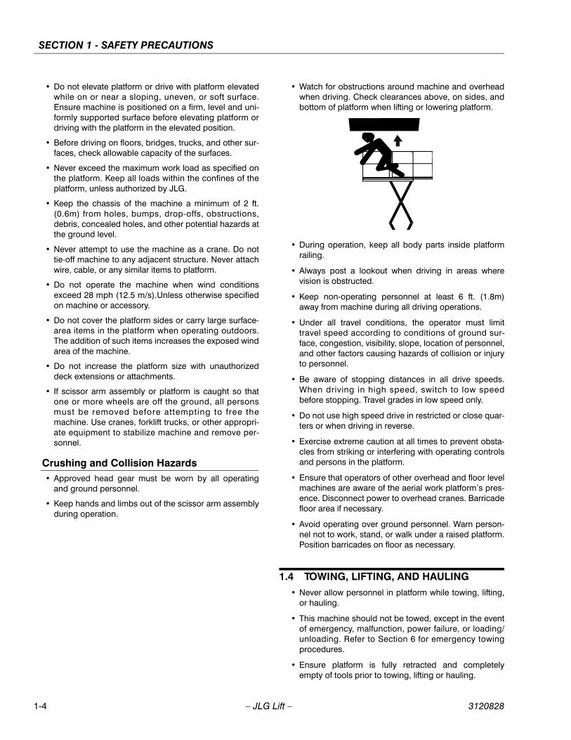
• Watch for obstructions around machine and overheadwhen driving. Check clearances above, on sides, andbottom of platform when lifting or lowering platform.
• During operation, keep all body parts inside platformrailing.
• Always post a lookout when driving in areas wherevision is obstructed.
• Keep non-operating personnel at least 6 ft. (1.8m)away from machine during all driving operations.
• Under all travel conditions, the operator must limittravel speed according to conditions of ground sur-face, congestion, visibility, slope, location of personnel,and other factors causing hazards of collision or injuryto personnel.
• Be aware of stopping distances in all drive speeds.When driving in high speed, switch to low speedbefore stopping. Travel grades in low speed only.
• Do not use high speed drive in restricted or close quar-ters or when driving in reverse.
• Exercise extreme caution at all times to prevent obsta-cles from striking or interfering with operating controlsand persons in the platform.
• Ensure that operators of other overhead and floor levelmachines are aware of the aerial work platform’s pres-ence. Disconnect power to overhead cranes. Barricadefloor area if necessary.
• Avoid operating over ground personnel. Warn person-nel not to work, stand, or walk under a raised platform.Position barricades on floor as necessary.
1.4 TOWING, LIFTING, AND HAULING• Never allow personnel in platform while towing, lifting,
or hauling.
• This machine should not be towed, except in the eventof emergency, malfunction, power failure, or loading/unloading. Refer to Section 6 for emergency towingprocedures.
• Ensure platform is fully retracted and completelyempty of tools prior to towing, lifting or hauling.
1-4 – JLG Lift – 3120828
SECTION 1 - SAFETY PRECAUTIONS
• When lifting machine with a forklift, position forks onlyat designated areas of the machine. Lift with a forklift ofadequate capacity.
• Refer to Section 4 for lifting information.
1.5 MAINTENANCE
General• This section contains general safety precautions which
must be observed during maintenance of this machine.Additional precautions to be observed during machinemaintenance are inserted at the appropriate points inthis manual and in the Service and Maintenance Man-ual. It is of utmost importance that maintenance per-sonnel pay strict attention to these precautions toavoid possible injury to personnel or damage to themachine or property. A maintenance program must beestablished by a qualified person and must be followedto ensure that the machine is safe.
Maintenance Hazards• Shut off power to all controls and ensure that all oper-
ating systems are secured from inadvertent motionprior to performing any adjustments or repairs.
• Never work under an elevated platform until it has beenfully lowered to the full down position, if possible, orotherwise supported and restrained from movementwith appropriate safety props, blocking, or overheadsupports.
• Always relieve hydraulic pressure from all hydraulic cir-cuits before loosening or removing hydraulic compo-nents.
• Always disconnect batteries when servicing electricalcomponents or when performing welding on themachine.
• Shut down the engine (if equipped) while fuel tanks arebeing filled.
• Ensure replacement parts or components are identicalor equivalent to original parts or components.
• Never attempt to move heavy parts without the aid of amechanical device. Do not allow heavy objects to restin an unstable position. Ensure adequate support isprovided when raising components of the machine
• Remove all rings, watches, and jewelry when perform-ing any maintenance. Do not wear loose fitting clothingor long hair unrestrained which may become caught orentangled in equipment.
• Use only clean approved non-flammable cleaning sol-vents.
• Never alter, remove, or substitute any items such ascounterweights, tires, batteries, platforms or other
items that may reduce or affect the overall weight orstability of the machine.
• Reference the Service and Maintenance Manual for theweights of critical stability items.
MODIFICATION OR ALTERATION OF AN AERIAL WORK PLAT-FORM SHALL BE MADE ONLY WITH PRIOR WRITTEN PERMIS-SION FROM THE MANUFACTURER
Battery Hazards• Always disconnect batteries when servicing electrical
components or when performing welding on themachine.
• Do not allow smoking, open flame, or sparks near bat-tery during charging or servicing.
• Do not contact tools or other metal objects across thebattery terminals.
• Always wear hand, eye, and face protection when ser-vicing batteries. Ensure that battery acid does notcome in contact with skin or clothing.
BATTERY FLUID IS HIGHLY CORROSIVE. AVOID CONTACT WITHSKIN AND CLOTHING AT ALL TIMES. IMMEDIATELY RINSE ANYCONTACTED AREA WITH CLEAN WATER AND SEEK MEDICALATTENTION.
• Charge batteries only in a well ventilated area.
• Avoid overfilling the battery fluid level. Add distilledwater to batteries only after the batteries are fullycharged.
3120828 – JLG Lift – 1-5

SECTION 1 - SAFETY PRECAUTIONS
NOTES:
1-6 – JLG Lift – 3120828

SECTION 2 - MACHINE PREPARATION AND INSPECTION
SECTION 2. MACHINE PREPARATION AND INSPECTION
2.1 GENERAL
This section provides the necessary information neededby those personnel that are responsible to place themachine in operation readiness, and lists checks that areperformed prior to use of the machine. It is important thatthe information contained in this section be read andunderstood before any attempt is made to operate themachine. Ensure that all the necessary inspections havebeen completed successfully before placing the machineinto service. These procedures will aid in obtaining maxi-mum service life and safe operation.
NOTICESINCE THE MACHINE MANUFACTURER HAS NO DIRECT CON-TROL OVER THE FIELD INSPECTION AND MAINTENANCE,SAFETY IS THE RESPONSIBILITY OF THE OWNER/OPERATOR.
2.2 PREPARATION FOR USE
1. Before a new machine is put into operation it mustbe carefully inspected for any evidence of damageresulting from shipment and inspected periodicallythereafter, as outlined in paragraph 2-3, Delivery andPeriodic Inspection. The unit should be thoroughlychecked for hydraulic leaks during initial start-upand run. A check of all components should be madeto assure their security.
2. All preparations necessary to place the machine inoperation readiness status are the responsibility ofmanagement personnel. Preparation requires goodcommon sense, (i.e. lift works smoothly and brakesoperate properly) coupled with a series of visualinspections. The mandatory requirements are givenin paragraph 2-4, Daily Walk Around Inspection.
3. It should be assured that the items appearing in theDelivery and Periodic Inspection and FunctionalCheck are complied with prior to putting themachine into service.
2.3 DELIVERY AND PERIODIC INSPECTION
NOTE: This machine requires periodic safety and mainte-nance inspections by a JLG Dealer.
The following checklist provides a systematic inspectionto assist in detecting defective, damaged, or improperlyinstalled parts. The checklist denotes the items to beinspected and conditions to examine.
Periodic inspection shall be performed monthly or moreoften when required by environment, severity, and fre-quency of usage.
This inspection checklist is also applicable and must befollowed for all machines that have been in storage or forall machines that will be exposed to harsh or changing cli-mates
Handrail AssembliesProperly installed; no loose or missing parts; no visibledamage.
Platform AssemblyNo visible damage; free of dirt and debris.
Sizzor ArmsNo visible damage, abrasions and/or distortions.
Electrical CableNo visible damage; properly secured.
Pivot PinsNo loose or missing retaining hardware; no damage orwear to pin heads which would cause pin to rotate; no evi-dence of pin or bushing wear.
Lift CylinderNo rust, nicks, scratches or foreign material on piston rod.No leakage. Evidence of proper lubrication.
FrameNo visible damage; loose or missing hardware (top andunderside).
Drive HubsCheck oil level in drive hub by removing pipe plug andfeeling for oil level. (Contact service personnel for assis-tance if needed.)
NOTE: Torque Hubs should be one-half full of lubricant.
Tire and Wheel AssembliesNo loose or missing lug nuts; no visible damage
Sliding Wear Pad BlocksNo excessive wear; adequate lubrication.
3120828 – JLG Lift – 2-1

SECTION 2 - MACHINE PREPARATION AND INSPECTION
Hydraulic Oil Supply
NOTE: Prior to checking the hydraulic oil level, operate themachine through one complete cycle of the lift func-tion (full up and down). Failure to do so will result inan incorrect oil level reading on the hydraulic tank.
Operate hydraulic systems through one complete cyclebefore checking oil level in hydraulic oil tank. Oil shouldbe visible in ADD sight window on hydraulic oil tank. If oilis not visible, add oil until oil is visible in both ADD andFULL sight windows on tank. Do not overfill tank.
Steer CylinderNo rust, nicks, scratches or foreign material on piston rod;no leakage.
Steer LinkageNo loose or missing parts; no visible damage.
Steer Spindle AssembliesNo excessive wear; no damage.
Control Boxes (Console and Ground)Switches operable; no visible damage; placards secureand legible. Hand controller operable; no visible damage.
BatteryProper electrolyte level; cable connections tight; no visibledamage; no corrosion at battery cable connections.
Engine Engine oil level - full mark on dipstick; filler cap secure; airfilter secure.
Hydraulic Pump and ValvesNo visible damage; no evidence of leakage; units secure.
Platform PlacardsNo visible damage; placards secure and legible.
Lock-Out Cylinders (If Equipped)No rust, nicks, scratches or foreign material on piston rod;no leakage.
Leveling Jacks (If Equipped)No rust, nicks, scratches or foreign material on piston rod;no leakage.
Traversing Platform (If Equipped)No loose or missing parts; no visible damage; free of dirtand debris.
2.4 DAILY WALK-AROUND INSPECTION
It is the user’s responsibility to inspect the machine beforethe start of each workday. It is recommended that eachuser inspect the machine before operation, even if themachine has already been put into service under anotheruser. This Daily Walk-Around Inspection is the preferredmethod of inspection.
In addition to the Daily Walk-Around Inspection, be sure toinclude the following as part of the daily inspection:
Overall Cleanliness
Check all standing surfaces for oil, fuel and hydraulic oilspillage and foreign objects. Ensure overall cleanliness.
Placards
Keep all information and operating placards clean andunobstructed. Cover when spray painting or shot blastingto protect legibility.
Operators and Safety Manual
Ensure a copy of this manual is enclosed in the manualstorage box.
Machine Log
Maintain an "Operating Record". Before operating themachine check the "Operating Record" to ensure it is notin an unsafe condition.
Daily Lubrication
For those items pointed out in the Daily Walk-AroundInspection requiring daily lubrication, refer to Figure 2-4.,Lubrication Diagram for specific requirements.
Perform the following checks and services before attempt-ing to operate the machine.
TO AVOID INJURY DO NOT OPERATE A MACHINE UNTIL ALLMALFUNCTIONS HAVE BEEN CORRECTED. USE OF A MALFUNC-TIONING MACHINE IS A SAFETY VIOLATION.
1. Ensure that all items requiring lubrication are ser-viced in accordance with the Lubrication Chart.
2. Perform functional checks in accordance with para-graph 2-5, Daily Functional Check.
2-2 – JLG Lift – 3120828

SECTION 2 - MACHINE PREPARATION AND INSPECTION
2.5 DAILY FUNCTIONAL CHECK
TO AVOID SERIOUS INJURY, DO NOT OPERATE MACHINE IF ANYCONTROL LEVERS OR TOGGLE SWITCHES CONTROLLINGPLATFORM MOVEMENT DO NOT RETURN TO THE OFF POSITIONWHEN RELEASED.
A functional check of all systems must be performed,under no load, in an area free of overhead and groundlevel obstructions. Perform the functional check in accor-dance with the following procedure once the walk-aroundinspection is complete:
1. From the ground control station, raise and lower theplatform several times and check for the following:
a. Smooth elevation and lowering.
b. High function speeds cut out as soon as possi-ble after the platform lifts beyond the stowedposition and begins to elevate. High functionspeeds must cut out prior to a maximum plat-form height of 4.2 m (14 ft).
c. If equipped with oscillating axles - Make surethat the axle lockout valve switch is free of debrisand the plunger of the switch actuates properly.As shown below, the plunger must extend (out)a minimum of 5.6 mm (0.22 in) to lock the axleswhen the scissor arms are raised. When fully
lowered, the scissor arms will press the plungerin to allow the axles to oscillate.
2. Ensure the machine is on a firm level surface. Checkfor proper operation of the leveling jack limit switchfirst from the ground control station and then fromthe platform controls. With all the leveling jacksretracted, check that the platform will not raiseabove the following limits:
400RTS - 8.0m (26ft) Approximate elevation 65%
500RTS - 6.7m (22ft) Approximate elevation 44%
3. Drive forward and reverse, check for proper opera-tion.
4. Check that drive brakes hold when machine isdriven up a hill, not to exceed rated gradeability, andstopped.
5. Steer left and right. Check for proper operation.
6. Check hydraulic oil reservoir sight gauge. Refer toLubrication Chart.
TO AVOID INJURY DO NOT OPERATE A MACHINE UNTIL ALLMALFUNCTIONS HAVE BEEN CORRECTED. USE OF A MALFUNC-TIONING MACHINE IS A SAFETY VIOLATION.
Min 5.6 mm (0.22 in.)
3120828 – JLG Lift – 2-3

SECTION 2 - MACHINE PREPARATION AND INSPECTION
Figure 2-1. Daily Walk-Around Inspection Diagram
2-4 – JLG Lift – 3120828

SECTION 2 - MACHINE PREPARATION AND INSPECTION
GENERALBegin the “Walk-Around Inspection” at Item 1, as notedon the diagram. Continue to the right (counterclockwiseviewed from top) checking each item in sequence for theconditions listed in the “Walk-Around Inspection Check-list”.
TO AVOID INJURY DO NOT OPERATE MACHINE UNTIL ALL MAL-FUNCTIONS HAVE BEEN CORRECTED. USE OF A MALFUNC-TIONING MACHINE IS A SAFETY VIOLATION. TO AVOIDPOSSIBLE INJURY, BE SURE MACHINE POWER IS “OFF” DUR-ING “WALK-AROUND INSPECTION”.
NOTICEDO NOT OVERLOOK VISUAL INSPECTION OF CHASSIS UNDER-SIDE. CHECKING THIS AREA OFTEN RESULTS IN DISCOVERYOF CONDITIONS WHICH COULD CAUSE EXTENSIVE MACHINEDAMAGE.
INSPECTION NOTE: On all components, make surethere are no loose or missing parts, that they are securelyfastened, and that no visible damage, leaks or excessivewear exists in addition to any other crtieria mentioned.
1. Steer Cylinder and Tie Rod Ends - See InspectionNote.
2. Leveling Jack, Left Front (If Equipped) - See Inspec-tion Note.
3. Drive and Lift Cutout Switches (If Equipped) - SeeInspection Note.
4. Steer Spindle, Left Front - Evidence of proper lubri-cation. See Inspection Note.
5. Steer/Drive Wheel and Tire Assembly, Left Front -Refer to inflation psi stenciled on frame. SeeInspection Note.
6. Drive Motor, Left Front (4 Wheel Drive) - See Inspec-tion Note.
7. Drive Brake, Left Front (4 Wheel Drive) - SeeInspection Note.
8. Drive Hub, Left Front (4 Wheel Drive) - Drive hubsshould be one half full of EPGL SAE 90. SeeInspection Note.
9. Traversing Platform Extension Cylinder (IfEquipped) - See Inspection Note.
10. Oscillating Axle (If Equipped) - See Inspection Note.
11. Ladder - See Inspection Note.
12. Hydraulic Reservoir - Recommended oil level insight glass. Breather cap secure and working. SeeInspection Note.
13. Ground Controls - Switches operable, no visibledamage, placards secure and legible.
14. Tilt Alarm Switch - See Inspection Note.
15. Hydraulic Filter - See Inspection Note.
16. Auxiliary Power Pump - See Inspection Note.
17. Control Valves - See Inspection Note.
18. Hand Pump Manual Descent - See Inspection Note.
19. Fuel Tank (Gasoline or Diesel Engine) - Filler capsecure, sight gauge visible, no damage or leaks.
20. Traversing Platform Extension Cylinder (IfEquipped) - See Inspection Note.
21. Travel/Descent/Motion Alarm - See Inspection Note.
22. Safety Prop - Stored securely, no missing parts.
23. Drive Wheel and Tire Assembly, Left Rear - Refer toinflation psi stenciled on frame.See InspectionNote.
24. Drive Motor, Left Rear - See Inspection Note.
25. Drive Brake, Left Rear - See Inspection Note.
26. Drive Hub, Left Rear - Drive hubs should be one halffull of EPGL SAE 90. See Inspection Note.
27. Steer Spindle, Left Rear (If Equipped) - Evidence ofproper lubrication.See Inspection Note.
28. LP Tank and Bracket (If Equipped) - See InspectionNote.
29. Leveling Jack, Left Rear (If Equipped) - See Inspec-tion Note.
30. Drive and Lift Cutout Switches (If Equipped) - SeeInspection Note.
31. Battery Installation (Gasoline or Diesel Engine) -See Inspection Note.
32. Ladder - See Inspection Note.
33. Traversing Platform (If Equipped) - See InspectionNote.
34. Leveling Jack, Right Rear (If Equipped) - SeeInspection Note.
35. Drive and Lift Cutout Switches (If Equipped) - SeeInspection Note.
36. Rear Steer Cylinder and Tie Rod Ends (If Equipped)- See Inspection Note.
Figure 2-2. Walk-Around Inspection Points (Sheet 1 of 2)
3120828 – JLG Lift – 2-5

SECTION 2 - MACHINE PREPARATION AND INSPECTION
37. LP Tank and Bracket (If Equipped) - See InspectionNote.
38. Steer Spindle, Right Rear (If Equipped) - Evidenceof proper lubrication. See Inspection Note.
39. Drive Wheel and Tire Assembly, Right Rear - Referto inflation psi stenciled on frame. See InspectionNote.
40. Drive Motor, Right Rear - See Inspection Note.
41. Drive Brake, Right Rear - See Inspection Note.
42. Drive Hub, Right Rear - Drive hubs should be onehalf full of EPGL SAE 90. See Inspection Note.
43. Safety Prop - Stored securely, no missing parts.
44. Traversing Platform Extension Cylinder (IfEquipped) - See Inspection Note.
45. Engine Installation - Engine oil to full mark on dip-stick, oil fillercap secure. Muffler/exhaust systemproperly secured, no leakage. Air filter assemblysecure, no loose or missing parts, element clean.Gasoline Engine Only - Radiator cap secure, cool-ant to correct level.
46. Hydraulic Pump - Pump properly secured, no visi-ble damage, no evidence of leakage. Hoses and fit-tings properly secured, no visible damage, noevidence of leaks.
47. Handrail installation - All railings securely attached,no damage or missing parts, chains securelyattached.
48. Sizzor Arms and Sliding Wear Pads - Inspect sizzorarm guards for damage and proper installation.See Inspection Note.
49. Ladder - See Inspection Note.
50. Lift Cylinder - See Inspection Note.
51. Traversing Platform Extension Cylinder (IfEquipped) - See Inspection Note.
52. Steer/Drive Wheel and Tire Assembly, Right Front -Refer to inflation psi stenciled on frame. SeeInspection Note.
53. Drive Motor, Right Front (4 Wheel Drive) - SeeInspection Note.
54. Drive Brake, Right Front (4 Wheel Drive) - SeeInspection Note.
55. Drive Hub, Right Front (4 Wheel Drive) - Drive hubsshould be one half full of EPGL SAE 90. SeeInspection Note.
56. Steer Spindle, Right Front - See Inspection Note.
57. High Speed Limit Switch - See Inspection Note.
58. Platform Controls - Properly secured, no loose ormissing parts, no visible damage. Placards secureand legible, control switches return to neutral. Con-trol markings legible, manual in manual storagebox.
59. Leveling Jack, Right Front (If Equipped) - SeeInspection Note.
60. Drive and Lift Cutout Switches (If Equipped) - SeeInspection Note.
61. Traversing Platform (If Equipped) - See InspectionNote.
62. Drive Cutout Switch and High Speed Cutout Switch- See Inspection Note.
63. Leveling Gauge - See Inspection Note.
64. Traversing Platform Valve (If Equipped) - SeeInspection Note.
65. Platform Assembly - See Inspection Note.
Figure 2-3. Walk-Around Inspection Points (Sheet 2 of 2)
2-6 – JLG Lift – 3120828

SECTION 2 - MACHINE PREPARATION AND INSPECTION
2.6 LOCKOUT CYLINDER CHECK (IF EQUIPPED)
To be performed quarterly, any time a system componentis replaced, or when improper system operation is sus-pected on machines with oscillating axles.
NOTE: Ensure platform is fully lowered prior to beginninglockout cylinder check.
1. Place a 20 cm (8 in) high block with ascension rampin front of the left front wheel.
2. Activate the machine’s hydraulic system from theplatform control station.
3. Place the engine speed and drive speed controlswitches to their respective “LOW” positions.
4. Place the drive controller to the “FORWARD” posi-tion and carefully drive the machine up the ascen-sion ramp until the left front wheel is on top of theblock.
5. Raise the machine platform approximately 61 cm (2ft); ensure the lockout cylinder cam valve is free ofthe sizzor arm trip bar.
6. Place the drive controller to the “REVERSE” positionand carefully drive the machine off of the block andramp.
7. Have an assistant check to see that the left frontwheel remains locked in position off of the ground.
8. Lower the machine platform; the lockout cylindershould then release the wheel and allow it to rest onthe ground.
9. If the lockout cylinder does not function properly,have qualified personnel correct the malfunctionprior to any further operation.
2.7 DUAL FUEL SYSTEM
IT IS POSSIBLE TO SWITCH FROM ONE FUEL SOURCE TO THEOTHER WITHOUT ALLOWING THE ENGINE TO STOP. EXTREMECARE MUST BE TAKEN AND THE FOLLOWING INSTRUCTIONSMUST BE FOLLOWED.
Changing from Gasoline to LP Gas
1. Start the engine from the ground control station.
2. Open the hand valve on the LP Gas supply tank byturning counterclockwise.
BE SURE ALL GASOLINE IS EXHAUSTED BEFORE SWITCHINGTO LP GAS.
3. While the engine is operating, place the three posi-tion LPG/GAS SELECT switch at the ground controlstation to the center OFF position. Allow the engineto operate, without load, until the engine begins to‘stumble’ from lack of gasoline.
4. As the engine begins to ‘stumble’ place the switch tothe LPG position, allowing the LP fuel to be sent tothe fuel regulator.
Changing from LP Gas to Gasoline
1. With engine operating on LP under a no-load condi-tion, position the LPG/GAS SELECT switch atground control to the GAS SELECT position.
2. If engine ‘stumbles’ because of lack of gasoline,place the switch to the LPG position until engineregains smoothness, then return the switch to theGAS SELECT position. Repeat as necessary untilengine runs smoothly on gasoline.
3. Close the hand valve on the LP gas supply tank byturning clockwise.
2.8 TORQUE REQUIREMENTSThe Torque Chart (See Figure 2-5.) consists of standardtorque values based on bolt diameter and grade, alsospecifying dry and wet torque values in accordance withrecommended shop practices. This chart is provided asan aid to the operator in the event he/she notices a condi-tion that requires prompt attention during the walk-aroundinspection or during operation until the proper service per-sonnel can be notified. Section 1 of the Service and Main-tenance Manual provides specific torque values andperiodic maintenance procedures with a listing of individ-ual components. Utilizing this Torque Chart in conjunctionwith the preventive maintenance section in Section 2 ofthe Service and Maintenance Manual, will enhance safety,reliability and performance of the machine.
3120828 – JLG Lift – 2-7

SECTION 2 - MACHINE PREPARATION AND INSPECTION
Fig
ure
2-4.
Lub
rica
tion
Dia
gra
m
2-8 – JLG Lift – 3120828

SECTION 2 - MACHINE PREPARATION AND INSPECTION
Table 2-1. Lubrication Chart
INDEX NO
COMPONENT NUMBER/TYPE LUBE POINTS LUBE METHODINTERVAL
HOURS
1 Oscillating Axle Pivot Point (Optional) 1 Grease Fitting MPG - Pressure Gun 100
2 Lockout Cylinders (Optional) 2 Grease Fittings (1 each cylinder) MPG - Pressure Gun 100
3 Front Steering Spindles (2-W/D) 2 Grease Fittings MPG - Pressure Gun 100
4 Front Steering Spindles (4-W/D) (Optional)
2 Grease Fittings MPG - Pressure Gun 100
5 Tow Bar Hitch (Optional) 1 Grease Fitting MPG - Pressure Gun 100
6 Wheel Bearings (2-W/D) N/A MPG - Repack 2000
7 *Wheel Drive Hub (4-W/D) (Optional) Fill Plug EPGL (SAE 90) 500
8 Hydraulic Oil Reservoir Fill Cap/Drain Plug HO - Check HO Level (See note 4)/HO - Change HO
10/500
9 ** Hydraulic Filter Element N/A Initial Change - 40 Hours 250
10 *Wheel Drive Hub Fill Plug EPGL (SAE 90) 500
11 Rear Steering Spindles (4-W/S) (Optional)
2 Grease Fittings MPG - Pressure Gun 100
12 400 RTS Sizzor Arm Pivot Pins500 RTS Sizzor Arm Pivot Pins
30 Grease Fittings (400 RTS)38 Grease Fittings (500RTS)
MPG - Pressure GunMPG - Pressure Gun
100
13 Rail Slides N/A MPG - Brush 100
14 Platform Extension Slides (Optional) N/A MPG - Brush 100
15 Lift Cylinder 4 Grease Fittings MPG - Pressure Gun 100
16 Engine Crankcase Fill Cap/Drain Plug Check Engine Oil Level 10/100
*Torque Hubs should be 1/2 full of lubricant
** JLG Industries recommends replacing the hydraulicfilter after the first 40 hours of operation and every 250hours thereafter.
KEY TO LUBRICANTS:
MPG - Multi-purpose Grease
EPGL - Extreme Pressure Gear Lube
HO - Hydraulic Oil (Mobil 424)
TO AVOID PERSONAL INJURY, USE SAFETY PROP FOR ALLMAINTENANCE REQUIRING PLATFORM TO BE ELEVATED.
NOTE: 1. Be sure to lubricate like items on each side2. Recommended lubricating intervals are basedon machine operations under normal conditions.For machines used in multi-shift operations and/orexposed to hostile environments or conditions,lubrication frequencies must be increased accord-ingly.3. Operate hydraulic functions through one com-plete cycle before checking hydraulic oil level intank. Oil should be visible in ADD sight window onhydraulic tank. If oil is not visible, add oil until oil isvisible in both ADD and FULL sight windows ontank. Do not overfill tank.4. Any time the pump coupling is removed, coatsplines of coupling with Texaco Code 1912 greaseprior to assembly. (gasoline or diesel engine only).
3120828 – JLG Lift – 2-9

SECTION 2 - MACHINE PREPARATION AND INSPECTION
Fig
ure
2-5.
To
rque
Ch
art
2-10 – JLG Lift – 3120828

SECTION 3 - USER RESPONSIBILITIES AND MACHINE CONTROL
SECTION 3. USER RESPONSIBILITIES AND MACHINE CONTROL
3.1 GENERAL
NOTICESINCE THE MANUFACTURER HAS NO DIRECT CONTROL OVERMACHINE APPLICATION AND OPERATION, CONFORMANCE WITHGOOD SAFETY PRACTICES IN THESE AREAS IS THE RESPONSI-BILITY OF THE USER AND HIS OPERATING PERSONNEL.
This section provides the necessary information neededto understand control functions. Included in this sectionare the operating characteristics and limitations, and func-tions and purposes of controls and indicators. It is impor-tant that the user read and understand the properprocedures before operating the machine. These proce-dures will aid in obtaining optimum service life and safeoperation.
3.2 PERSONNEL TRAINING
The sizzor lift is a personnel handling device; therefore, itis essential that it be operated and maintained only byauthorized personnel who have demonstrated that theyunderstand the proper use and maintenance of themachine. It is important that all personnel who areassigned to and responsible for the operation and mainte-nance of the machine undergo a thorough training pro-gram and check out period in order to become familiarwith the characteristics prior to operating the machine.
In addition, personnel operating the machine should befamiliar with ANSI standard A92.6-1990 Responsibilities.This standard contains sections outlining the responsibili-ties of the owners, users, operators, lessors and lesseesconcerning safety, training, inspection, maintenance,application and operation.
Persons under the influence of drugs or alcohol or whoare subject to seizures, dizziness or loss of physical con-trol must not be permitted to operate the machine.
Operator Training
Operator training must include instruction in the following:
1. Use and limitations of the platform controls, groundcontrols, emergency controls and safety systems.
2. Knowledge and understanding of this manual and ofthe control markings, instructions and warnings onthe machine itself.
3. Knowledge and understanding of all safety workrules of the employer and of Federal, State andLocal Statutes, including training in the recognitionand avoidance of potential hazards in the workplace; with particular attention to the work to be per-formed.
4. Proper use of all required personnel safety equip-ment.
5. Sufficient knowledge of the mechanical operation ofthe machine to recognize a malfunction or potentialmalfunction.
6. The safest means to operate near overhead obstruc-tions, other moving equipment, obstacles, depres-sions, holes, dropoffs, etc. on the supportingsurface.
7. Means to avoid the hazards of unprotected electricalconductors.
8. Any other requirements of a specific job or machineapplication.
Training Supervision
Training must be done under the supervision of a qualifiedoperator or supervisor in an open area free of obstructionsuntil the trainee has developed the ability to safely controla sizzor lift in congested work locations.
Operator Responsibility
The operator must be instructed that he has the responsi-bility and authority to shut down the machine in case of amalfunction or other unsafe condition of either themachine or the job site and to request further informationfrom his supervisor or JLG Distributor before proceeding.
NOTE: Manufacturer or Distributor will provide qualified per-sons for training assistance with first unit(s) deliv-ered and thereafter as requested by user or hispersonnel.
3.3 OPERATING CHARACTERISTICS AND LIMITATIONS
General
A thorough knowledge of the operating characteristicsand limitations of the machine is always the first require-ment for any user, regardless of user’s experience withsimilar types of equipment.
3120828 – JLG Lift – 3-1

SECTION 3 - USER RESPONSIBILITIES AND MACHINE CONTROL
PlacardsImportant points to remember during operation are pro-vided at the control stations by DANGER, WARNING,CAUTION, IMPORTANT and INSTRUCTION placards. Thisinformation is placed at various locations for the expresspurpose of alerting personnel of potential hazards consti-tuted by the operating characteristics and load limitationsof the machine. See foreword for definitions of the aboveplacards.
CapacitiesRaising platform above stowed position with or withoutany load in platform, is based on the following criteria:
1. Machine is positioned on a smooth, firm and levelsurface.
2. Load is within manufacturer’s rated capacity.
3. All machine systems are functioning properly.
4. Leveling Jacks properly set (If Equipped).
Stability
This machine, as originally manufactured by JLG andoperated within its rated capacity on a smooth, firm andlevel supporting surface, provides a stable aerial platformfor all platform positions.
3.4 CONTROLS AND INDICATORS
Ground Control Station
DO NOT OPERATE FROM GROUND CONTROL STATION WITHPERSONNEL IN THE PLATFORM EXCEPT IN AN EMERGENCY.
PERFORM AS MANY PRE-OPERATIONAL CHECKS AND INSPEC-TIONS FROM THE GROUND CONTROL STATION AS POSSIBLE.
Platform/Ground Control Switch
Fuel Select Switch
Voltmeter
Emergency Stop Switch
Engine Start Button
Platform ExtensionSelect
Lift SwitchHourmeter
WaterTemperature
Engine OilTemperature
15 Amp Breaker(Diesel Only)
Platform ExtensionSwitch
Figure 3-1. Ground Control Station
3-2 – JLG Lift – 3120828

SECTION 3 - USER RESPONSIBILITIES AND MACHINE CONTROL
1. Ignition/Emergency Stop - A two-position, redmushroom shaped switch supplies electrical powerto the Start button when positioned up. When posi-tioned down, the switch shuts off electrical power tothe ignition circuit, acting as an emergency stopswitch.With the MAIN POWER switch in the OFFposition, the key can be removed in order to inca-pacitate the machine on the jobsite to avoid unau-thorized use of the machine.
2. Power Selector Switch - A three position key-oper-ated power selector switch supplies operatingpower to the platform or ground controls, asselected. When positioned to platform, the switchprovides power to the platform controls. When posi-tioned to ground, the switch provides power to theground controls. With the power selector switch inthe center off position, power is shut off to both plat-form and ground controls.
NOTE: With the PLATFORM/GROUND SELECT switchpositioned to GROUND, engine speed will stay inLOW at all times.
3. Lift Switch - A three position, momentary contact liftcontrol switch provides raising and lowering of theplatform when positioned to UP or down.
4. High Engine Circuit Breaker (Diesel Engine) - Apush button reset 3 Amp circuit breaker located onground control panel returns interrupted power todiesel engine throttle when depressed.
5. Start Button - A momentary contact, push-buttontype switch supplies electrical power to the startersolenoid when the IGNITION switch is positioned upand the START button is depressed.
6. Choke Switch (If Equipped) - A momentary con-tact, push-button type switch supplies power to thechoke solenoid, when depressed, to assist cold startoperation.
7. Platform Extension Switch (If Equipped) - A dou-ble throw, momentary contact toggle-type platformtraversing switch permits the operator to hydrauli-cally extend and retract the platform extension asneeded for “up and over” work access.
8. Platform Extension Select Switch (If Equipped) -A full throw, momentary contact toggle-type platformtraversing select switch that works simultaneouslywith the platform traversing switch to permits theoperator to hydraulically extend and retract the rearplatform extension as needed for “up and over”work access.
9. Gasoline/LPG Select Switch (Duel Fuel Only) - Athree position toggle-type switch is used to selectthe desired method of powering the unit. Placing theswitch in the gasoline position shuts off the fuel flow
from the lp gas supply tank and allows fuel flow fromthe gasoline tank. Moving the switch to the lpg posi-tion shuts off fuel flow from the gasoline tank andallows lp gas from supply tank to be used to powerthe unit. With the switch in the center position, fuelflow is restricted from both supply tanks.
10. Hourmeter - The hourmeter records engine or elec-tric motor operating time.
11. Voltmeter - With the emergency stop switch in theup position, and before starting the engine, the volt-meter indicates output voltage of the alternator. Nor-mal reading for the voltmeter will be 12-14 volts witha properly charged or charging battery.
12. Water Temperature Gauge - The water temperaturegauge provides a visual display of the engine cool-ant temperature.
13. Oil Pressure Gauge - The oil pressure gauge dis-plays the engine lubrication system operating pres-sure.
Platform Control Station
1. Enable Switch - These machines are equipped withan enable switch on the side of the platform controlconsole. On machines built with a serial numberbefore 0200058922, the enable switch must bepressed before activating the drive, lift or steer func-tions. A built-in timer shuts off power to these func-tions if they are not activated within 3 seconds afterthe enable switch is depressed. In addition, thistimer will shut off power to the drive and lift functions3 seconds after they are deactivated, making if nec-essary to depress the enable switch before activat-ing drive and lift again. The steer function, unlessactivated in conjunction with the drive or lift func-tions, will automatically cut off after 3 seconds ofoperation. On machines built from, and including,serial number 0200058922, the enable switch mustbe depressed and held for the duration of lift. Theenable switch works in conjunction with the liftswitch only.
2. Ignition/Emergency Stop Switch - An ignition/emergency stop red mushroom-type switch is pro-vided in order to turn on machine power in the plat-form and also to turn off machine power in the eventof an emergency. Power is turned on by positioningthe switch to the up (on) position, and is turned offby positioning the switch to the down (off) position.
3. Start Button - A momentary contact, push-button-type switch that supplies electrical power to thestarter solenoid when the ignition/emergency stopswitch is in the on position and the start button isdepressed.
3120828 – JLG Lift – 3-3
SECTION 3 - USER RESPONSIBILITIES AND MACHINE CONTROL
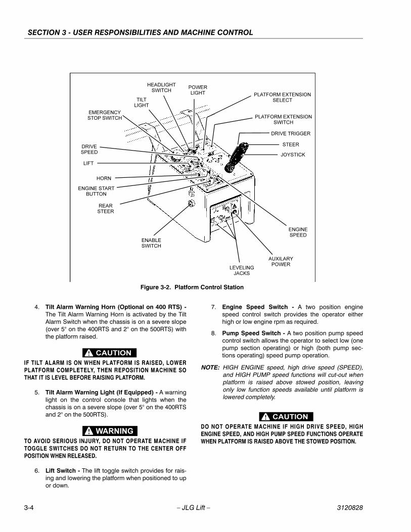
4. Tilt Alarm Warning Horn (Optional on 400 RTS) -The Tilt Alarm Warning Horn is activated by the TiltAlarm Switch when the chassis is on a severe slope(over 5° on the 400RTS and 2° on the 500RTS) withthe platform raised.
IF TILT ALARM IS ON WHEN PLATFORM IS RAISED, LOWERPLATFORM COMPLETELY, THEN REPOSITION MACHINE SOTHAT IT IS LEVEL BEFORE RAISING PLATFORM.
5. Tilt Alarm Warning Light (If Equipped) - A warninglight on the control console that lights when thechassis is on a severe slope (over 5° on the 400RTSand 2° on the 500RTS).
TO AVOID SERIOUS INJURY, DO NOT OPERATE MACHINE IFTOGGLE SWITCHES DO NOT RETURN TO THE CENTER OFFPOSITION WHEN RELEASED.
6. Lift Switch - The lift toggle switch provides for rais-ing and lowering the platform when positioned to upor down.
7. Engine Speed Switch - A two position enginespeed control switch provides the operator eitherhigh or low engine rpm as required.
8. Pump Speed Switch - A two position pump speedcontrol switch allows the operator to select low (onepump section operating) or high (both pump sec-tions operating) speed pump operation.
NOTE: HIGH ENGINE speed, high drive speed (SPEED),and HIGH PUMP speed functions will cut-out whenplatform is raised above stowed position, leavingonly low function speeds available until platform islowered completely.
DO NOT OPERATE MACHINE IF HIGH DRIVE SPEED, HIGHENGINE SPEED, AND HIGH PUMP SPEED FUNCTIONS OPERATEWHEN PLATFORM IS RAISED ABOVE THE STOWED POSITION.
Figure 3-2. Platform Control Station
3-4 – JLG Lift – 3120828

SECTION 3 - USER RESPONSIBILITIES AND MACHINE CONTROL
9. PQ Controller - The PQ Controller performs threefunctions: Drive, Steer and Drive Speed. On allmachines built before serial number 0200058922,tilting the controller in the direction you want to go(forward or reverse) activates drive in that direction.The thumb-operated steer switch on top of the con-troller handle activates the steer wheels in the direc-tion it is moved. If machine is equipped with fourwheel steer, this switch operates only the front steerwheels. On all machines built after, and including,serial number 0200058922 there is a red triggerswitch on the front of the controller. This switch mustbe depressed and held in order to drive themachine.
10. Auxiliary Power (If Equipped) - A toggle type auxil-iary power control switch energizes the electrically-operated hydraulic pump, when actuated. Switchmust be held ON for the duration of auxiliary pumpuse.
The auxiliary power pump functions to provide sufficientoil flow to operate the Traversing Platform Extensionsshould the main pump or engine fail during operation.
It should be noted that the functions will operate at aslower than normal rate because of the lower GPM deliv-ered.
NOTE: Auxiliary power pump only operates the TraversingPlatform Extensions.
11. Platform Traversing Switch (If Equipped) - This isa double throw, momentary contact toggle-typeswitch which permits the operator to hydraulicallyextend and retract the platforms as needed for “upand over” work access.
12. Platform Traversing Select Switch (If Equipped) -In order to select the platform to traverse there is afull throw, momentary contact toggle-type platformtraversing select switch, that works in conjunctionwith the platform traversing switch to permit theoperator to hydraulically extend and retract the plat-forms as needed for “up and over” work access.
13. Travel Warning Horn - A push-button type hornswitch supplies electrical power to an audible warn-ing device when pressed.
14. Choke (If Equipped) - A push-button type switchsupplies power, when depressed, to the choke sole-noid for cold start operations.
15. Leveling Jacks (If Equipped) - The four momentarycontact type toggle switches correspond to the fourleveling jacks, one at each corner of the machine.
BE AWARE OF OTHER PERSONNEL AND EQUIPMENT WHENEXTENDING OR RETRACTING LEVELING JACKS.
16. Engine Distress Light (Gasoline Engine) - Theengine distress light is connected to a sensor on theengine that detects when coolant temperature risesabove a preset level, illuminating the warning light.
17. Engine Distress Light (Diesel Engine) - Theengine distress light is connected to a sensor on theengine that detects when oil pressure falls below apreset level, illuminating the warning light
3120828 – JLG Lift – 3-5
SECTION 3 - USER RESPONSIBILITIES AND MACHINE CONTROL
BB
B-B
VIE
W
C-C
VIE
W
A-A
VIE
W
12
3
4
19 20 21
56
7
22
23
5
22 23 5
24 25
4
9
10
2611
1213
1415
1416
1112
13
1018
17
17
19
4
2626
26
Fig
ure
3-3.
Dec
al L
oca
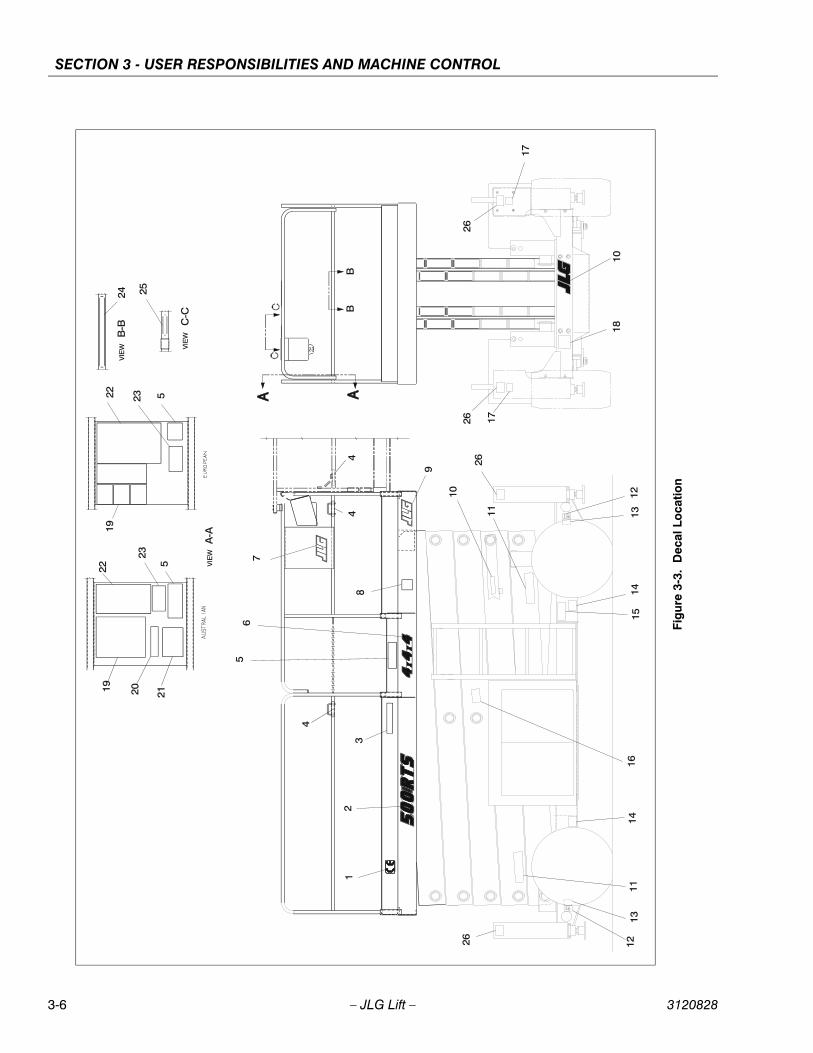
tion
3-6 – JLG Lift – 3120828

SECTION 3 - USER RESPONSIBILITIES AND MACHINE CONTROL
Table 3-1. Decal Location Legend
Item #Australian0257581-4
Dutch0253525-3
CE/English0253521-5
German0253523-4
Italian0272857-3
Spanish0253526-3
Norwegian0273217-1
1 N/A 1705084 1705084 1705084 1705084 1705084 1705084
2400RTS500RTS
17020121701838
17020121701838
17020121701838
17020121701838
17020121701838
17020121701838
17020121701838
3 1703662 N/A N/A N/A N/A N/A N/A
4 N/A N/A N/A N/A N/A N/A N/A
5400RTS
(Fixed Platform)400RTS
(Single Extension)400RTS
(Dual Extension)500RTS
(Fixed Platform)500RTS
(Single Extension)500RTS
(Dual Extension)
3252573
3252574
3252575
3252576
3252577
3252578
3252573
3252574
3252575
3252576
3252577
3252578
3252573
3252574
3252575
3252576
3252577
3252578
3252573
3252574
3252575
3252576
3252577
3252578
3252573
3252574
3252575
3252576
3252577
3252578
3252573
3252574
3252575
3252576
3252577
3252578
3252573
3252574
3252575
3252576
3252577
3252578
64x4x44x4x24x2x44x2x2
1701836170183517018341701833
1701836170183517018341701833
1701836170183517018341701833
1701836170183517018341701833
1701836170183517018341701833
1701836170183517018341701833
1701836170183517018341701833
7 1701871 1701871 1701871 1701871 1701871 1701871 1701871
8 1702631 1702631 1702631 1702631 1702631 1702631 1702631
9 1701871 1701871 1701871 1701871 1701871 1701871 1701871
10 1701839 1701615 1701839 1701519 1701524 1701856 1701839
11 N/A N/A N/A N/A N/A N/A N/A
12 1703814 1703814 1703814 1703814 1703814 1703814 1703814
13 1703811 1703811 1703811 1703811 1703811 1703811 1703811
14 1704525 1704525 1704525 1704525 1704525 1704525 1704525
15 N/A N/A N/A N/A N/A N/A N/A
16 1701839 1701839 1701839 1701839 1701839 1701839 N/A
17 1703795 1703795 1703795 1703795 1703795 1703795 1703795
18 N/A N/A N/A N/A N/A N/A N/A
19 1703921 1703921 1703921 1703921 1703921 1703921 1703921
3120828 – JLG Lift – 3-7

SECTION 3 - USER RESPONSIBILITIES AND MACHINE CONTROL
20 1703663 N/A N/A N/A N/A N/A N/A
21 1703665 N/A N/A N/A N/A N/A N/A
22 1701523 1701617 1701523 1701516 1701520 1701860 1701523
23 3252263 3252267 3252263 3252265 3252266 3252268 1705274
24 N/A N/A N/A N/A N/A N/A N/A
25 N/A N/A N/A N/A N/A N/A N/A
26 1701785 1701785 1701785 1701785 1701785 1701785 1701785
Table 3-1. Decal Location Legend
Item #Australian0257581-4
Dutch0253525-3
CE/English0253521-5
German0253523-4
Italian0272857-3
Spanish0253526-3
Norwegian0273217-1
3-8 – JLG Lift – 3120828

SECTION 4 - MACHINE OPERATION
SECTION 4. MACHINE OPERATION
4.1 DESCRIPTION
This machine is a self-propelled elevating ‘sizzor’ aerialwork platform. The Sizzor Lift’s intended purpose is toposition personnel with their tools and supplies at posi-tions above ground level. The machine can be used toreach work areas located above machinery or equipment.
The JLG Sizzor Lift has a primary operator Control Stationin the platform. From this Control Station, the operator candrive and steer the machine in both forward and reversedirections as well as raise and lower the platform. Themachine has a Ground Control Station which will overridethe Platform Control Station. Ground Controls operate LiftUp, Lift Down, and Platform Traversing, (If Equipped). Thecontrols are to be used only for daily check or in an emer-gency to lower the platform to the ground should theoperator in the platform be unable to do so.
Instructions and hazard warnings are posted adjacent toboth operator control stations and at other places on themachine. It is extremely important that operators knowwhat instructions and warnings are placed on themachine, and review these periodically so that they arefresh in their minds.
The JLG Sizzor Lift is designed to provide efficient andsafe operation when maintained and operated in accor-dance with warnings on the machine, the Operators &Safety, Service and Maintenance Manual and all jobsiteand government rules and regulations. As with any type ofmachinery, the operator is very important to efficient andsafe operation. Owner/user/operator must be familiar withSections 6, 7, 8, 9, and 10 of ANSI A92.6-1990. These sec-tions contain the responsibilities of the owner, users, oper-ators, lessors and lessees concerning safety, training,inspection, maintenance, application and operation. It isabsolutely necessary that the JLG Lift be regularly main-tained in accordance with this section, and that any evi-dence of lack of maintenance, malfunction, excessivewear, damage or modification to the machine be reportedimmediately to the machine owner or the jobsite supervi-sor or safety manager and that the machine be taken outof service until all discrepancies are corrected.
The JLG Sizzor Lift is not intended to be used to lift mate-rial other than supplies which personnel in the platformrequire to do their job. Supplies or tools which extend out-side the platform are prohibited. It must not be used as aforklift, crane, support for overhead structure, or to pushor pull another object.
The machine has a manual descent system which willallow the platform to lowered without power from theengine/motor powered pump.
The JLG Sizzor Lift is powered using hydraulic motors andcylinders for the various machine motions. The hydrauliccomponents are controlled by electrically activatedhydraulic valves using switches and the joystick controller.The machine is equipped with an Enable Switch whichmust be pressed before activating the DRIVE, LIFT orSTEER functions. The Enable Switch has a built-in timerwhich shuts off power to these functions if they are notactivated within 3 seconds after Enable Switch isdepressed. The speeds of functions controlled by the joy-stick controller are variable from zero to maximum speeddepending upon the position of the controller. Functionscontrolled by toggle switches are either on or off. Higheror lower speed is possible only when the applicable highfunction speed control switch at the Platform Control Sta-tion is used in conjunction with the drive function. Allswitches at the platform are guarded to prevent inadvert-ant operation by individual switch guards.
The JLG Sizzor is a two or four wheel drive machine withdrive power being supplied by a hydraulic motor for eachdrive wheel. Each drive wheel is supplied with a hydrauli-cally released, spring applied brake. The brakes are auto-matically applied anytime the Drive controller is returnedto the neutral position.
The capacities of model 400RTS and 500RTS are foundon the capacity decals located on the machine. Thesecapacities are based on a load uniformly distributed in thecenter of the platform. This means that the total combinedweight of personnel, tools and supplies must not exceedthe given capacity for a particular model.
The platform may be raised only when positioned on firm,level and uniform surfaces. Leveling jacks, if provided, areto assist in leveling the Sizzor Lift. The Sizzor Lift must belevel when operating on leveling jacks.
3120828 – JLG Lift – 4-1

SECTION 4 - MACHINE OPERATION
4.2 GENERAL
This section provides the necessary information neededto operate the machine. Included in this section are theprocedures for starting, stopping, traveling, steering, park-ing, platform loading and transporting. It is important thatthe user read and understand the proper proceduresbefore operating the machine.
4.3 ENGINE OPERATION
NOTICERTS SERIES SCISSOR LIFTS MANUFACTURED AFTER AUGUST26, 1996 ARE EQUIPPED WITH A HYDRAULIC OIL TEMPERATURESWITCH THAT SHUTS DOWN THE ENGINE WHEN THE HYDRAU-LIC OIL REACHES A TEMPERATURE OF APPROXIMATELY 111˚C(230˚F). THIS SHUT DOWN IS INTENDED TO PROTECT THEHYDRAULIC SYSTEM AND ITS COMPONENTS FROM DAMAGEDUE TO EXCESSIVE HEAT. HEAT MAY BUILD UP DUE TOEXTENDED DRIVING, IN CONJUNCTION WITH HIGH AMBIENTTEMPERATURES, ACTIVATING THIS SWITCH AND SHUTTINGDOWN THE MACHINE. IF THE MACHINE SHUTS DOWN, ALLOWTHE HYDRAULIC OIL TO COOL, THEN RESUME NORMAL OPERA-TION.
NOTE: Initial starting should always be performed from theGround Control Station.
Starting Procedure
1. Check engine oil before attempting to start engine; ifnecessary, add oil in accordance with Engine Manu-facturers Manual.
2. Pull the red mushroom-type Ignition/EmergencyStop switch at the Ground Control Station to the UPposition (ON).
3. Place the PLATFORM/GROUND SELECT switch tothe applicable position for desired control stationoperation.
4. If operating a dual fuel machine, place the LP/GAS-OLINE SELECT switch to the desired position.
NOTE: If LPG system is selected, ensure that the handvalve on the LPG supply tank is opened prior toattempting to start the engine.
NOTICEIF ENGINE FAILS TO START PROMPTLY, DO NOT CRANK FOR ANEXTENDED PERIOD. SHOULD ENGINE FAIL TO START ONCEAGAIN, ALLOW STARTER TO “COOL OFF” FOR 2 TO 3 MINUTES.IF ENGINE FAILS TO START AFTER SEVERAL ATTEMPTS, REFERTO ENGINE MAINTENANCE MANUAL.
NOTE: If starting machine from the platform control station,place the engine speed control switch to the LOWposition prior to starting the engine.
5. If starting machine from ground controls, positionIGNITION/EMERGENCY STOP switch to ON anddepress START button and hold until engine starts.If starting from platform controls, position POWERON switch to ON and depress START button andhold until engine starts.
6. Check engine voltmeter when starting engine andmonitor gauge periodically during operation.
NOTICEALLOW ENGINE TO WARM-UP FOR A FEW MINUTES AT LOWSPEED BEFORE APPLYING ANY LOAD.
7. After engine has had sufficient time to warm up, pro-ceed with operation of unit.
Table 4-1. Operating Specifications
Model 400RTS 500RTS
Maximum Occupants 4 4
Maximum Workload (Capacity)Extension Only:
680 kg 900 kg
Maximum Travel Grade (Gradeability) 2 WD4WD
35%45%
35%45%
Maximum Travel Grade (Sideslope) 2 degreess 2 degreess
Maximum Platform Height 12.1m 15.2m
Maximum Tire Load Reference Decal on Machine
Approximate Maximum Drive Speed2 Wheel Drive4 Wheel Drive
5.6 kmh4.5 kmh
5.6 kmh4.5 kmh
Approximate Gross Machine Weight 6,797 kg 6,940 kg
4-2 – JLG Lift – 3120828
SECTION 4 - MACHINE OPERATION
4.4 RAISING AND LOWERING (LIFTING)
DO NOT RAISE PLATFORM EXCEPT ON A FIRM, LEVEL SURFACEFREE OF OBSTRUCTIONS AND HOLES.
NOTE: This machine is equipped with a Enable Switch onthe side of the platform control console. This switchmust be depressed before activating DRIVE, LIFT, orSTEER functions from the platform control console.
Raising
NOTE: On machines equipped with leveling jacks, levelingjacks must be in contacted with the ground for liftsystem to raise above 6.7 m. (22 ft).
1. Position MAIN POWER switch to desired positionand position POWER ON (platform) or EMERGENCYSTOP (ground) switch, as applicable, to ON. Ifmachine has been shut down, start engine andallow warm-up period before beginning any lifting.
2. Pull LIFT toggle switch, then move it to UP and holduntil desired elevation is achieved.
Lowering
ENSURE SIZZOR ARM AREA IS FREE OF PERSONNEL PRIOR TOLOWERING PLATFORM.DO NOT ‘LIFT DOWN’ WITHOUT COMPLETELY RETRACTING THEOPTIONAL TRAVERSING DECK.
Pull LIFT toggle switch, then move it to DOWN and holduntil desired elevation is achieved or until platform is fullylowered.
4.5 TRAVERSING PLATFORM (OPTIONAL)
The machine may be equipped with hydraulically oper-ated traversing platforms that moves 1.2 m (4 ft) at eachend of the machine to give the operator “up and over”access to worksites. The traversing platform is operatedby either the TRAVERSE toggle switches at platform con-trol console or the TRAVERSE toggle switch at the groundcontrol switches.
TO AVOID INJURY TO GROUND PERSONNEL, RETRACT TRA-VERSING PLATFORM COMPLETELY BEFORE LOWERING PLAT-FORM.
4.6 STEERINGTo steer the machine, the thumb operated steer controlswitch on the controller handle is positioned to the rightfor traveling right, or to the left for traveling left.
To steer the machine with the optional 4 wheel steer, posi-tion steer control switch to right for traveling right, or to leftfor traveling left.
When released, the switch will return to the center-off posi-tion and the wheels will remain in the previously selectedposition. To return the wheels to the straightened position,the switch must be activated in the opposite direction untilthe wheels are centered.
4.7 TRAVELING (DRIVING)
ALWAYS RAISE LEVELING JACKS, IF EQUIPPED, BEFORE TRAV-ELING TO AVOID INJURY TO PERSONNEL OR DAMAGE TOMACHINE.
IF EQUIPPED WITH LEVELING JACKS, DRIVE FUNCTION IS CUTOUT WHEN LEVELING JACKS ARE IN THE SET POSITION.
IF MACHINE BECOMES STUCK DURING TRAVEL, DO NOT“ROCK” MACHINE IN AN ATTEMPT TO REGAIN TRACTION, ASDAMAGE TO DRIVE HUBS MAY RESULT.
DO NOT DRIVE WITH PLATFORM RAISED EXCEPT ON ASMOOTH, FIRM, AND LEVEL SURFACE FREE OF OBSTRUCTIONSAND HOLES.
TO AVOID LOSS OF CONTROL OR UPSET ON GRADES ANDSIDESLOPES, DO NOT DRIVE MACHINE ON GRADES EXCEED-ING THOSE SPECIFIED FOR THE MACHINE. TRAVEL GRADESAND SIDESLOPES WITH PLATFORM COMPLETELY LOWERED
3120828 – JLG Lift – 4-3

SECTION 4 - MACHINE OPERATION
.
TRAVEL GRADES IN “LOW” DRIVE SPEED ONLY. USE EXTREMECAUTION WHEN DRIVING IN REVERSE AND AT ALL TIMES WHENDRIVING WITH PLATFORM ELEVATED AND ESPECIALLY WHENDRIVING WITH ANY PART OF MACHINE WITHIN 2 M (6 FT) OF ANOBSTRUCTION.
HIGH DRIVE SPEED IS CUT OUT WHEN PLATFORM IS RAISEDABOVE STOWED POSITION. IF LIMIT SWITCH MALFUNCTIONS,SHUT DOWN MACHINE AND HAVE AUTHORIZED SERVICE PER-SONNEL REPAIR OR REPLACE LIMIT SWITCH PRIOR TO RESUM-ING OPERATION.
THE 400RTS MAY BE EQUIPPED WITH A 5 DEGREES TILTSWITCH THAT ILLUMINATES A LIGHT ON THE PLATFORM CON-TROL CONSOLE AND SOUNDS AN AUDIBLE ALARM WHEN THEMACHINE IS ON A SLOPE (OVER 5 DEGRESS) WITH THE PLAT-FORM RAISED.
THE 500RTS IS EQUIPPED WITH A 2 DEGREES TILT SWITCHTHAT ILLUMINATES A LIGHT ON THE PLATFORM CONTROLCONSOLE AND SOUNDS AN AUDIBLE ALARM WHEN THEMACHINE IS ON A SLOPE (OVER 2 DEGREES) WITH THE PLAT-FORM RAISED. WHEN MACHINE IS ON A SLOPE (OVER 2DEGREES) WITH THE PLATFORM COMPLETELY LOWERED,ONLY THE WARNING LIGHT IS ILLUMINATED.
Traveling Forward
NOTE: On machines equipped with leveling jacks, levelingjacks must be in the stowed position before opera-tion of the drive system.
1. Position ignition/emergency stop switch to on. Ifmachine has been shut down, start engine andallow warm-up period before beginning any lifting.
2. Position pump and engine control switches todesired positions (high or low) and position drivecontrol switch to desired position (torque or speed).
3. Position controller to forward, pull up on safety lock,and hold controller in position for duration of travel.Once drive is initiated, the safety lock can bereleased and drive will continue to function until con-troller is returned to the center off position. Drivespeed is determined by the distance the controller ismoved from the center off position.
Figure 4-1. Grade and Sideslope
4-4 – JLG Lift – 3120828

SECTION 4 - MACHINE OPERATION
Traveling in Reverse
NOTE: On machines equipped with leveling jacks, levelingjacks must be in the stowed position before opera-tion of the drive system.
1. Position ignition/emergency stop switch to on. Ifmachine has been shut down, start engine andallow warm-up period before beginning any lifting.
2. Position pump and engine control switches todesired positions (high or low) and position drivecontrol switch to desired position (torque or speed).
3. Position controller to forward, pull up on safety lock,and hold controller in position for duration of travel.Once drive is initiated, the safety lock can bereleased and drive will continue to function until con-troller is returned to the center off position. Drivespeed is determined by the distance the controller ismoved from the center off position.
4.8 PARKING AND STOWING
Park and stow machine as follows:
1. Drive machine to a reasonably well-protected andwell-ventilated area.
2. Ensure platform is fully lowered.
3. Position emergency stop switch to off position.
4. If necessary, cover the instruction placards, cautionand warning decals so that they will be protectedfrom hostile environment.
5. Chock at least two wheels when parking machine foran extended period of time.
6. Turn ignition/emergency stop switch to off and turnthe Power selctor switch to the center position andremove key to disable machine from unauthorizeduse.
4.9 PLATFORM LOADING
The platform maximum rated load capacity is shown on aplacard located on the platform and is based upon the fol-lowing criteria.
1. Machine is positioned on a smooth, firm and levelsurface.
2. All braking devices are engaged.
3. Refer to Section 3 for platform capacities.
4. Leveling Jacks properly set (If Equipped).
It is important to remember that the load should be evenlydistributed on the platform. The load should be placednear the center of the platform when possible.
4.10 SAFETY PROPS
SAFETY PROPS MUST BE USED WHEN MAINTENANCE PER-FORMED ON MACHINE REQUIRES SIZZOR ARMS TO BE RAISED.
To engage safety props, raise platform so that both propscan be disconnected from locking arms and lowered to avertical position. Lower the platform until the safety propsrest on the pads provided on the frame. Maintenance cannow begin.
To store safety props, raise platform so that props can bepivoted up and secured by their locking arms.
4.11 MACHINE TIE DOWNWhen transporting machine, platform must be fullyretracted in the stowed mode with machine securely tieddown to truck or trailer deck. Four tie down lugs are pro-vided, one at each corner of the machine frame.
USE TIE DOWN LUGS ONLY TO SECURE THE MACHINE FORSHIPPING. DO NOT USE TIE DOWN LUGS TO LIFT MACHINE.
4.12 TOWINGThe machine should not be towed, except in the event ofan emergency such as a machine malfunction or a totalmachine power failure. Refer to Section 6 for emergencytowing procedures.
3120828 – JLG Lift – 4-5

SECTION 4 - MACHINE OPERATION
NOTES:
4-6 – JLG Lift – 3120828

SECTION 5 - EMERGENCY PROCEDURES
SECTION 5. EMERGENCY PROCEDURES
5.1 GENERAL
This section provides information on the procedures to befollowed and on the systems and controls to be used inthe event an emergency situation is encountered duringmachine operation. Prior to operation of the machine andperiodically thereafter, the entire operating manual, includ-ing this section, should be reviewed by all personnelwhose responsibilities include any work or contact withthe machine.
5.2 EMERGENCY TOWING PROCEDURES
Although towing the machine is prohibited, when notequipped with a tow package, provisions for moving themachine, in case of a malfunction or power failure, havebeen incorporated. The following procedures are to beused ONLY for emergency movement to a suitable main-tenance area.
1. Chock wheels securely.
2. Disengage (reverse) the disconnect cap on eachdrive torque hub by removing the two attaching cap-screws, turning the cap around, and reinstalling andtightening the capscrews.
3. Remove chocks and move the machine to an appro-priate maintenance area, using suitable equipmentfor assistance.
After moving machine, complete the following proce-dures:
1. Position machine on a firm, level surface.
2. Chock wheels securely.
3. Return disconnect caps to normal (engaged) posi-tion.
4. Remove chocks from wheels.
5.3 EMERGENCY CONTROLS AND THEIR LOCATIONS
Emergency Stop SwitchAt platform controls, push red Ignition/Emergency stopswitch this will immediately stop the machine.
Ground Control StationThe Ground Control Station is located on the left side ofthe machine frame. The controls on this panel provide themeans for overriding the platform controls and for control-ling the platform lift up and down and ignition functionsfrom the ground. Position the Ignition/Emergency Stopswitch to ON, position the PLATFORM/ GROUND SELECTswitch to the GROUND position and operate the theappropriate switch, LIFT or IGNITION.
NOTICEIF MACHINE IS EQUIPPED WITH PLATFORM EXTENSION OR TRA-VERSING DECK, RETRACT DECK BEFORE LOWERING PLAT-FORM.
Manual Descent (Engine/Pump Failure - Platform Controls)In the event of engine/pump failure while operating themachine from the platform console, the following proce-dure should be followed to lower the platform. Turn thepower on switch to on. Place the lift control switch todown. When platform is completely down, return lift con-trol switch to center off and position power on switch tooff.
Figure 5-1. Drive Hub Disconnect
Figure 5-2. Drive Hub Connect
3120828 – JLG Lift – 5-1

SECTION 5 - EMERGENCY PROCEDURES
Manual Descent (Engine/Pump Failure - Ground Controls)
The following procedure should be used to lower the plat-form from the ground controls in the event of engine/pump failure. Turn main power switch to on and platform/ground select switch to ground. For battery poweredmachines, position main power switch to ground. Place liftcontrol switch to down. When platform is completelydown, return lift control switch to center off and positionmain power switch to off.
Manual Descent (Complete Loss of Power)
The manual descent valve is used, in the event of totalpower failure, to lower the platform using gravity. Themanual descent handle is located on the inside of thevalve compartment on the left side of the machine. Turnthe release valve on the side of the pump to the closedposition and pump the handle. This will release the hold-ing valve, lowering the platform. After the platform reachesthe stowed position, open the release valve on the pump.
Auxiliary Power (If Equipped) (Engine/Pump Failure - Platform Controls)
A toggle type auxiliary power control switch is located onthe platform control station. Operation of switch turns onthe electrically driven auxiliary hydraulic pump. Thisshould be used in the case of failure of the main powerplant. The auxiliary pump will operate “only” the traversingplatforms. To activate auxiliary power:
1. Position IGNITION switch to off.
2. Operate appropriate control switch for desired func-tion and hold.
3. Position AUXILIARY POWER switch to ON and hold.
4. Release AUXILIARY POWER switch and selectedcontrol switch.
Auxiliary Power (If Equipped) (Engine/Pump Failure - Ground Controls)
The toggle type traversing platform control switches arelocated on the ground control station. Operation of switchturns on the electrically driven auxiliary hydraulic pump.
1. Position IGNITION switch to off.
2. Operate appropriate control switch for desired tra-versing platform function and hold.
5.4 EMERGENCY OPERATION
Use of Ground Controls
NOTICEKNOW HOW TO USE THE GROUND CONTROLS IN AN EMER-GENCY SITUATION.
Ground personnel must be thoroughly familiar with themachine operating characteristics and the ground controlfunctions. Training should include operation of themachine, review and understanding of this section andhands-on operation of the controls in simulated emergen-cies.
Operator Unable to Control Machine
If the platform operator is pinned, trapped or unable tooperate or control the machine.
1. USE THE MANUAL DESCENT SYSTEM AS FIRSTCHOICE for bringing the platform and operatordown, particularly IF THERE IS INDICATION OFCONTROL MALFUNCTION. Further use of hydraulicpower may cause severe injury or death.
2. Operate the machine from ground controls ONLYwith the assistance of other personnel and equip-ment (cranes, overhead hoists, etc.) as may berequired to safely remove the danger or emergencycondition.
3. Other qualified personnel on the platform may usethe platform controls. DO NOT CONTINUE OPERA-TION IF CONTROLS DO NOT FUNCTION NOR-MALLY.
4. Cranes, forklift trucks or other equipment which maybe available are to be used to remove platformoccupants and stabilize motion of the machine incase machine controls are inadequate or malfunc-tion when used.
Platform Caught Overhead
If the platform becomes jammed or snagged in overheadstructures or equipment, do not continue operation of themachine from either the platform or the ground until theoperator and all personnel are safely moved to a securelocation. Only then should an attempt be made to free theplatform using any necessary equipment and personnel.Do not operate controls to cause one or more wheels toleave the ground.
5-2 – JLG Lift – 3120828

SECTION 5 - EMERGENCY PROCEDURES
Righting of Tipped MachineA forktruck of suitable capacity or equivalent equipmentshould be placed under the elevated side of the chassis,with a crane or other suitable lifting equipment used to liftthe platform while the chassis is lowered by the forklift orother equipment.
Post-Incident InspectionFollowing any accident, thoroughly inspect the machineand test all functions first from the ground controls, thenfrom the platform controls. Do not lift above 3 m (10 ft)until you are secure that all damage has been repaired, ifrequired, and that all controls are operating correctly.
5.5 INCIDENT NOTIFICATIONIt is imperative that JLG Industries, Inc. be notified imme-diately of any incident involving a JLG product. Even if noinjury or property damage is evident, the factory shouldbe contacted by telephone and provided with all neces-sary details. Contact at 1-877-JLG-SAFE (554-7233)between the hours of 8:00 AM - 4:45 PM Eastern Standardtime.
It should be noted that failure to notify the Manufacturer ofan incident involving a JLG Industries product within 48hours of such an occurrence may void any warranty con-sideration on that particular machine.
3120828 – JLG Lift – 5-3
SECTION 5 - EMERGENCY PROCEDURES
NOTES:
5-4 – JLG Lift – 3120828

SECTION 6 - INSPECTION AND REPAIR LOG
SECTION 6. INSPECTION AND REPAIR LOG
Table 6-1.Inspection and Repair Log
Date Comments
3120828 – JLG Lift – 6-1
SECTION 6 - INSPECTION AND REPAIR LOG
Table 6-1.Inspection and Repair Log
Date Comments
6-2 – JLG Lift – 3120828

Corporate Office
JLG Industries, Inc.
1 JLG Drive
McConnellsburg PA. 17233-9533
USA
(717) 485-5161
(717) 485-6417
JLG Worldwide Locations
JLG Industries (Australia)P.O. Box 511911 Bolwarra RoadPort MacquarieN.S.W. 2444Australia
+61 2 65 811111
+61 2 65 810122
JLG Latino Americana Ltda.Rua Eng. Carlos Stevenson,80-Suite 7113092-310 Campinas-SPBrazil
+55 19 3295 0407
+55 19 3295 1025
JLG Industries (UK) LtdBentley HouseBentley AvenueMiddletonGreater ManchesterM24 2GP - England
+44 (0)161 654 1000
+44 (0)161 654 1001
JLG France SASZ.I. de Baulieu47400 FauilletFrance
+33 (0)5 53 88 31 70
+33 (0)5 53 88 31 79
JLG Deutschland GmbHMax-Planck-Str. 21D - 27721 Ritterhude - IhlpohlGermany
+49 (0)421 69 350 20
+49 (0)421 69 350 45
JLG Equipment Services Ltd.Rm 1107 Landmark North39 Lung Sum AvenueSheung Shui N. T.Hong Kong
(852) 2639 5783
(852) 2639 5797
JLG Industries (Italia) s.r.l.Via Po. 2220010 Pregnana Milanese - MIItaly
+39 029 359 5210
+39 029 359 5845
JLG Europe B.V.Polaris Avenue 632132 JH HoofddorpThe Netherlands
+31 (0)23 565 5665
+31 (0)23 557 2493
JLG PolskaUI. Krolewska00-060 WarsawaPoland
+48 (0)914 320 245
+48 (0)914 358 200
JLG Industries (Scotland)Wright Business Centre1 Lonmay RoadQueenslie, Glasgow G33 4ELScotland
+44 (0)141 781 6700
+44 (0)141 773 1907
Plataformas Elevadoras JLG Iberica, S.L.Trapadella, 2P.I. Castellbisbal Sur08755 Castellbisbal, BarcelonaSpain
+34 93 772 4700
+34 93 771 1762
JLG Sverige ABEnkopingsvagen 150Box 704SE - 176 27 JarfallaSweden
+46 (0)850 659 500
+46 (0)850 659 534
www.jlg.com