Embed Size (px)
Citation preview
Models:
AccuValve On/Off Valve A2 Cutting Head DiaLine Cutting head
13084 ON/OFF VALVE & CUTTING HEAD MANUAL
TABLE OF CONTENTS
1 Introduction ............................................................................................................................... 1 2 Safety .......................................................................................................................................... 2
2.1 Operation and Maintenance Safety ............................................................................................. 2 3 Inlet Cutting Water Requirements .......................................................................................... 4
Water Treatment Guidelines: .................................................................................................................... 4 4 AccuValve On/Off Valve........................................................................................................... 5
4.1 Specifications.................................................................................................................................. 5 4.2 Mounting Collar ............................................................................................................................ 6
Mounting Collar Installation..................................................................................................................... 6 4.3 Valve Body Maintenance .............................................................................................................. 7
Valve Body Components .......................................................................................................................... 7 4.4 Actuator Maintenance................................................................................................................... 9
Actuator Housing Disassembly................................................................................................................. 9 Actuator Reassembly .............................................................................................................................. 10
Cutting Heads.................................................................................................................................. 11 4.5 DiaLine Cutting Head ................................................................................................................. 11
Installing the DiaLine Head .................................................................................................................... 11 4.6 A2 Cutting head ........................................................................................................................... 12
Installing the A2 Cutting Head ............................................................................................................... 12 4.7 Replaceable Parts ........................................................................................................................ 13
Optimal Cutting Parameters.................................................................................................................... 14 4.8 Troubleshooting (Cutting head) ................................................................................................. 15
5 Drawings and Parts Lists........................................................................................................ 16
13084 ON/OFF VALVE & CUTTING HEAD MANUAL
AccuStream Cutting Systems 1
13084 ON/OFF VALVE & CUTTING HEAD MANUAL
1 Introduction
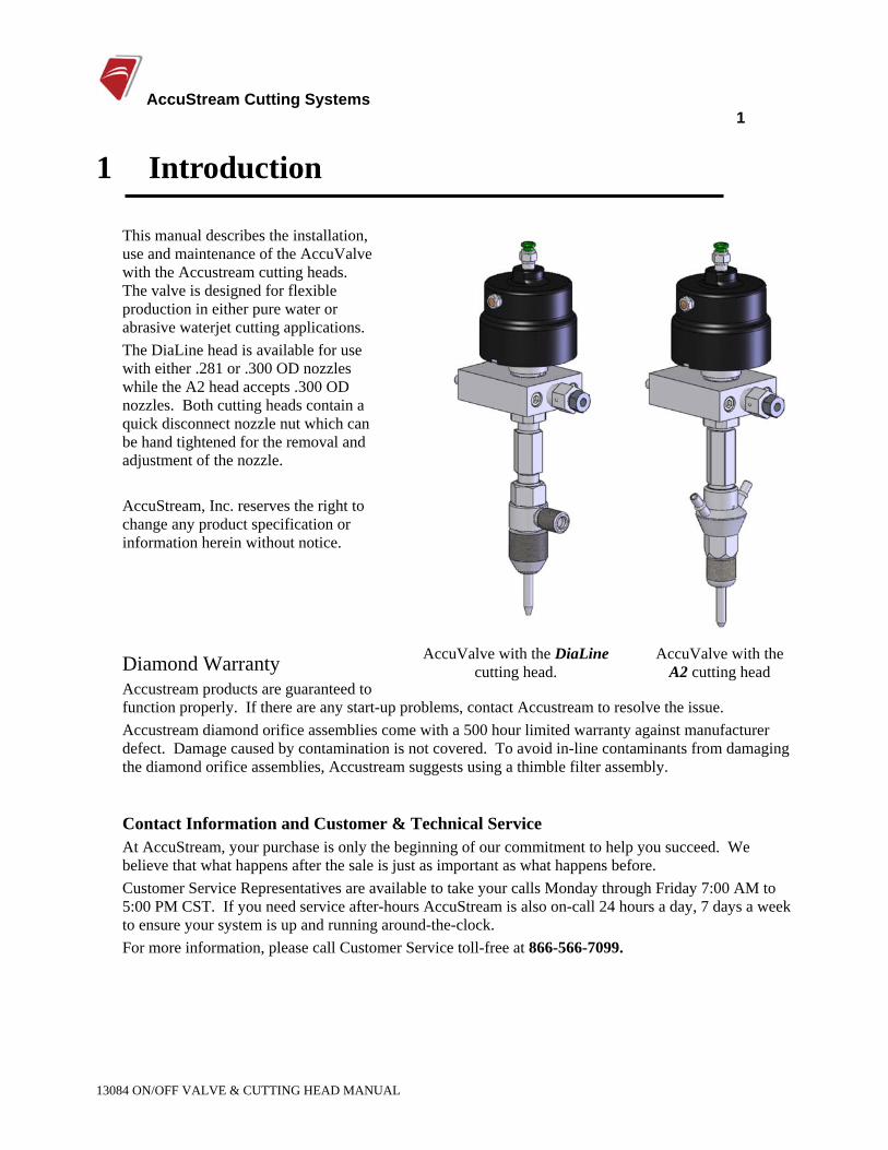
This manual describes the installation, use and maintenance of the AccuValve with the Accustream cutting heads. The valve is designed for flexible production in either pure water or abrasive waterjet cutting applications. The DiaLine head is available for use with either .281 or .300 OD nozzles while the A2 head accepts .300 OD nozzles. Both cutting heads contain a quick disconnect nozzle nut which can be hand tightened for the removal and adjustment of the nozzle. AccuStream, Inc. reserves the right to change any product specification or information herein without notice.
Diamond Warranty Accustream products are guaranteed to function properly. If there are any start-up problems, contact Accustream to resolve the issue.
AccuValve with the DiaLine cutting head.
AccuValve with the A2 cutting head
Accustream diamond orifice assemblies come with a 500 hour limited warranty against manufacturer defect. Damage caused by contamination is not covered. To avoid in-line contaminants from damaging the diamond orifice assemblies, Accustream suggests using a thimble filter assembly.
Contact Information and Customer & Technical Service At AccuStream, your purchase is only the beginning of our commitment to help you succeed. We believe that what happens after the sale is just as important as what happens before. Customer Service Representatives are available to take your calls Monday through Friday 7:00 AM to 5:00 PM CST. If you need service after-hours AccuStream is also on-call 24 hours a day, 7 days a week to ensure your system is up and running around-the-clock. For more information, please call Customer Service toll-free at 866-566-7099.
AccuStream Cutting Systems 2
13084 ON/OFF VALVE & CUTTING HEAD MANUAL
2 Safety 2.1 Operation and Maintenance Safety
Failure to wear proper safety gear can result in personal injury or death. Safety shoes, hardhat, hearing protection and other personal protective equipment are strongly recommended.
High-pressure waterjet can cause eye injury. Wear eye protection when operating or working near the machine.
Wear ear protection when operating or working near the machine to reduce the risk of hearing loss.
Airborne contaminants or suspended particles may exist when cutting certain materials. Wear respiratory protection when these conditions are present.
WARNING
• Before starting any service or maintenance, to the valve and/or cutting heads ALL water pressure must be removed from the system.
• Isolate the water pressure from the on/off valve by dumping the pump pressure or closing the manual isolation valve.
• Read the instructions in all sections of this manual before performing any maintenance on the
valve. Important information is contained throughout this manual to minimize hazards and wear on the machine.
• Use the proper tools required for specific procedures. When special tools are called for, make sure to use them because they are specifically designed to make the job easier and prevent damage to the equipment.
• Remove all tools from the work area before starting the machine.
AccuStream Cutting Systems 3
13084 ON/OFF VALVE & CUTTING HEAD MANUAL
High Pressure Water System Safety Never work on any high-pressure component or loosen any high pressure fittings without first bleeding the system to ensure that there is no high pressure water present. Follow all instructions and safety recommendations in this manual.
WARNING
Always avoid contact with the stream of water. Seek immediate surgical attention if you come in contact with any high pressure stream of fluid.
• Do not come in contact with the high pressure water. HP water can penetrate any part of the human body and cause severe infection or death if not treated properly. Seek immediate surgical attention if you come in contact with any high pressure stream of fluid.
• Do not try to repair a leak in an HP water fitting when the system is pressurized. A leak at a sealing surface can cause a hazardous spray of water. Shut off the motor and double check the HP water pressure is relieved down the drain before servicing any high-pressure plumbing.
• Plumbing supports and guides must be used for all HP tubing exiting the pump. Failure to do so can introduce excessive bending stress and fatigue through vibration causing a premature failure of the plumbing, and heighten the risk of personal injury due to an unexpected rupture.
• Always use two wrenches when tightening or loosening HP connections: one for the gland nut and one for the fitting. Using one wrench only will introduce excessive bending stress to the plumbing causing premature failure.
• Always use high-pressure piping that is rated for the pressures you will be operating with. This pump is capable of outputting 60,000 psi of water.
• Make sure all connections are properly tightened after performing service or maintenance.
• Keep hands and body away from pinholes and nozzles, which eject fluids under high pressure.
• Never check for hydraulic leaks with your hand: use a piece of cardboard or other material.
• Do not expose skin to a pressurized leak.
• Wear appropriate protective equipment including heavy gloves and safety glasses.
• Do not attempt to tighten or loosen any mechanical connection unless the machine is powered OFF and all system pressure has been relieved.
AccuStream Cutting Systems 4
13084 ON/OFF VALVE & CUTTING HEAD MANUAL
3 Inlet Cutting Water Requirements The inlet water should have a pH of 6 to 8 and be clear, odorless, and free of biological materials. The water quality should be analyzed to insure the incoming water will not have and adverse affect on the waterjet system. The water quality analysis should measure for:
• pH • Silica Content • Total Dissolved Solids (TDS)
Most systems just need water softening to pre-treat the inlet cutting water. Poor water quality may require other types of treatments to remove the high levels of TDS. One approach is to have the local water conditioning company provide de-ionizing (DI) tanks on an exchange basis, or install a reverse osmosis (RO) system. The RO approach is best for high gallon-per-day users.
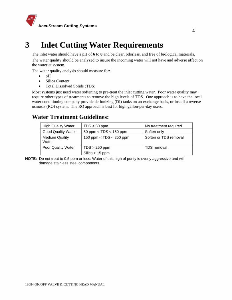
Water Treatment Guidelines: High Quality Water TDS < 50 ppm No treatment required Good Quality Water 50 ppm < TDS < 150 ppm Soften only Medium Quality Water
150 ppm < TDS < 250 ppm Soften or TDS removal
Poor Quality Water TDS > 250 ppm Silica > 15 ppm
TDS removal
NOTE: Do not treat to 0.5 ppm or less: Water of this high of purity is overly aggressive and will damage stainless steel components.
AccuStream Cutting Systems 5
13084 ON/OFF VALVE & CUTTING HEAD MANUAL
4 AccuValve On/Off Valve The Accustream On/Off Valve (AccuValve) is an ultra high-pressure valve used to control the flow of water for waterjet cutting applications. The On/Off valve is a normally closed (air to open, spring closed) valve that can be direct mounted to the cutting head for water or abrasivejet cutting see Mounting Collar (below), or it can be remote mounted with separate plumbing from the valve to the cutting head. The valve can also be remotely mounted on the cutting head.
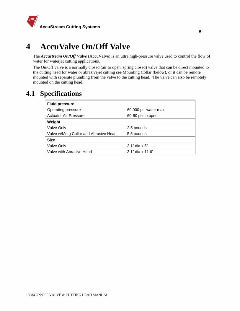
4.1 Specifications Fluid pressure Operating pressure 60,000 psi water max Actuator Air Pressure 60-80 psi to open Weight Valve Only 2.5 pounds Valve w/Mntg Collar and Abrasive Head 5.5 pounds Size Valve Only 3.1” dia x 5” Valve with Abrasive Head 3.1” dia x 11.6”
AccuStream Cutting Systems 6
13084 ON/OFF VALVE & CUTTING HEAD MANUAL
4.2 Mounting Collar
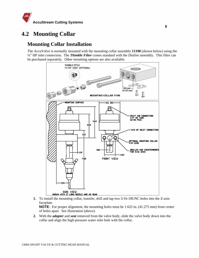
Mounting Collar Installation The AccuValve is normally mounted with the mounting collar assembly 11198 (shown below) using the ¼” HP inlet connection. The Thimble Filter comes standard with the Dialine assembly. This filter can be purchased separately. Other mounting options are also available.
1. To install the mounting collar, transfer, drill and tap two 5/16-18UNC holes into the Z-axis
faceplate. NOTE: For proper alignment, the mounting holes must be 1.625 in. (41.275 mm) from center of holes apart. See illustration (above).
2. With the adapter and seat removed from the valve body, slide the valve body down into the collar and align the high-pressure water inlet hole with the collar.
AccuStream Cutting Systems 7
13084 ON/OFF VALVE & CUTTING HEAD MANUAL
3. Align the bottom of the seal weep hole with the top of the mounting collar. Carefully thread and tighten the inlet fitting into the side of the valve body. NOTE: Make sure that the mating cones are properly aligned before torquing the connection.
4. Connect the inlet water connection to the inlet adapter. This connection is normally made with ¼” OD x .083 ID 60,000 psi rated stainless steel tubing. Tighten all high-pressure connections with a two wrench technique.
5. Connect regulated air pressure to the valve actuator. 6. Set the air pressure to 70 psi. The valve actuator should be controlled with a 3-way solenoid
valve. When the solenoid valve is energized, the actuator will pressurize and the actuator should exhaust when the solenoid valve is de-energized. NOTE: When installing a new valve it is best to flush the lines at low pressure with the adapter and seat out of the valve body. This step is optional.
7. Put AccuGoop at the seat hole and on the mating surfaces. With water pressure off, turn on the actuator. This removes spring force from the needle.
8. Thread the adapter with the seat on top into the valve body. Tighten the adapter to the valve body with two wrenches.
9. Turn the actuator off, this will seat the needle into the seat. 10. Turn on the pump or open up the manual isolation valve to apply high-pressure water to the
valve. 11. Flush the lines by actuating the on/off valve with brief pulses. After five to ten pulses, the lines
should be flushed and free of contamination. The cutting head can now be installed onto the adapter. See the Accustream cutting head manual.
4.3 Valve Body Maintenance The valve consists of two parts; the actuator and the high-pressure valve area. The actuator can go for extended periods without service. The high-pressure valve components require service more frequently.
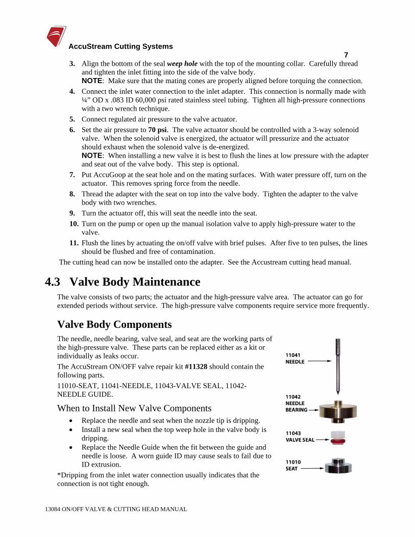
Valve Body Components The needle, needle bearing, valve seal, and seat are the working parts of the high-pressure valve. These parts can be replaced either as a kit or individually as leaks occur. The AccuStream ON/OFF valve repair kit #11328 should contain the following parts. 11010-SEAT, 11041-NEEDLE, 11043-VALVE SEAL, 11042-NEEDLE GUIDE.
When to Install New Valve Components • Replace the needle and seat when the nozzle tip is dripping. • Install a new seal when the top weep hole in the valve body is
dripping. • Replace the Needle Guide when the fit between the guide and
needle is loose. A worn guide ID may cause seals to fail due to ID extrusion.
*Dripping from the inlet water connection usually indicates that the connection is not tight enough.
AccuStream Cutting Systems 8
13084 ON/OFF VALVE & CUTTING HEAD MANUAL
alve.
Removing the valve body components. 1. Isolate the water pressure from the ON/OFF valve by dumping the pump pressure or closing
the manual isolation valve. 2. Turn the actuator ON and verify that there is NO water pressure. 3. With the actuator pressurized with air, unthread the adapter from the bottom of the valve body
and remove the seat from the bottom. 4. Turn the air to the actuator OFF and REMOVE the airline from the top of the actuator. 5. Unthread the actuator from the top of the valve body. 6. With the valve body still in the mounting collar, remove the seal components by using the seal
removal tool 11205 and push up through the bottom of the valve body. 7. Thoroughly wash out the interior of the Valve Body before replacing components.
NOTE: The needle guide ID may have build-up of seal material at the bottom of the .093 dia section. After extensive use, this build-up may stop the needle from closing. If the Guide ID is going to be re-used, it must be cleaned. A .093 drill bit can be used, to manually remove this material.
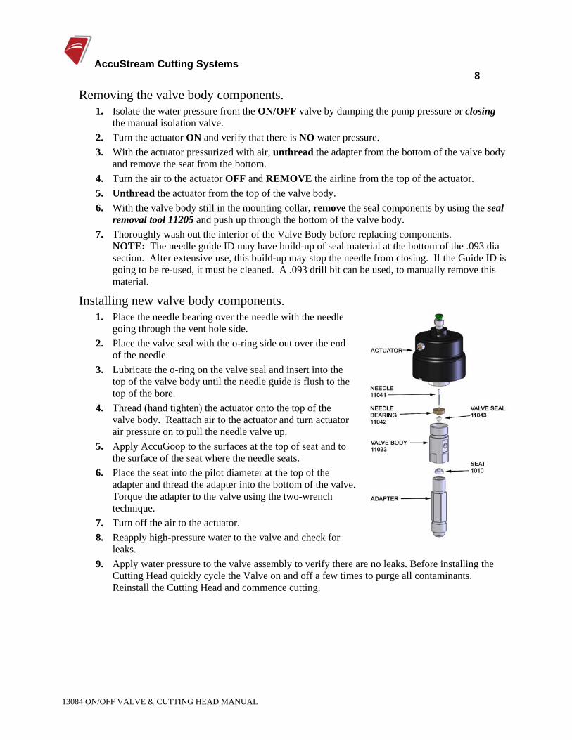
Installing new valve body components. 1. Place the needle bearing over the needle with the needle
going through the vent hole side. 2. Place the valve seal with the o-ring side out over the end
of the needle. 3. Lubricate the o-ring on the valve seal and insert into the
top of the valve body until the needle guide is flush to the top of the bore.
4. Thread (hand tighten) the actuator onto the top of the valve body. Reattach air to the actuator and turn actuator air pressure on to pull the needle valve up.
5. Apply AccuGoop to the surfaces at the top of seat and to the surface of the seat where the needle seats.
6. Place the seat into the pilot diameter at the top of the adapter and thread the adapter into the bottom of the vTorque the adapter to the valve using the two-wrench technique.
7. Turn off the air to the actuator. 8. Reapply high-pressure water to the valve and check for
leaks. 9. Apply water pressure to the valve assembly to verify there are no leaks. Before installing the
Cutting Head quickly cycle the Valve on and off a few times to purge all contaminants. Reinstall the Cutting Head and commence cutting.
AccuStream Cutting Systems 9
13084 ON/OFF VALVE & CUTTING HEAD MANUAL
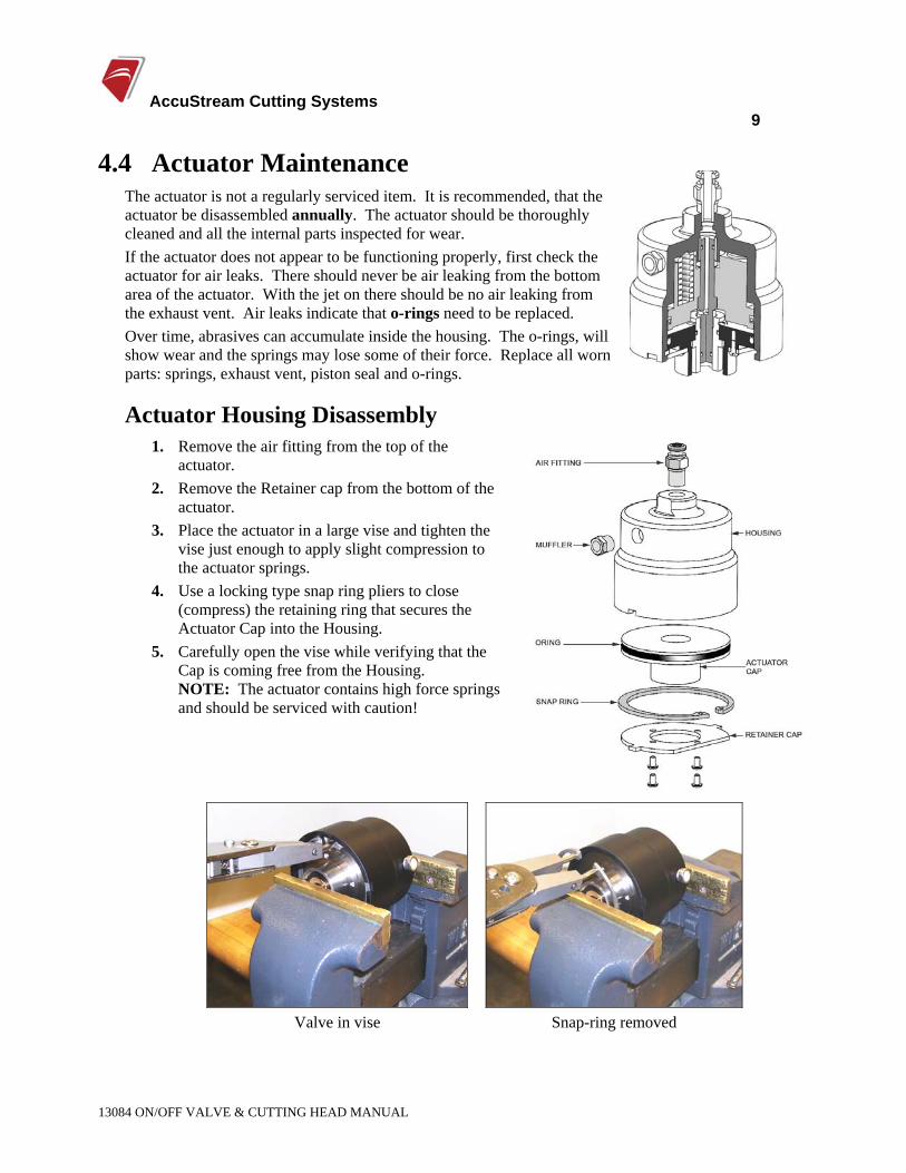
4.4 Actuator Maintenance The actuator is not a regularly serviced item. It is recommended, that the actuator be disassembled annually. The actuator should be thoroughly cleaned and all the internal parts inspected for wear. If the actuator does not appear to be functioning properly, first check the actuator for air leaks. There should never be air leaking from the bottom area of the actuator. With the jet on there should be no air leaking from the exhaust vent. Air leaks indicate that o-rings need to be replaced. Over time, abrasives can accumulate inside the housing. The o-rings, will show wear and the springs may lose some of their force. Replace all worn parts: springs, exhaust vent, piston seal and o-rings.
Actuator Housing Disassembly 1. Remove the air fitting from the top of the
actuator. 2. Remove the Retainer cap from the bottom of the
actuator. 3. Place the actuator in a large vise and tighten the
vise just enough to apply slight compression to the actuator springs.
4. Use a locking type snap ring pliers to close (compress) the retaining ring that secures the Actuator Cap into the Housing.
5. Carefully open the vise while verifying that the Cap is coming free from the Housing. NOTE: The actuator contains high force springs and should be serviced with caution!
Valve in vise Snap-ring removed
AccuStream Cutting Systems 10
13084 ON/OFF VALVE & CUTTING HEAD MANUAL
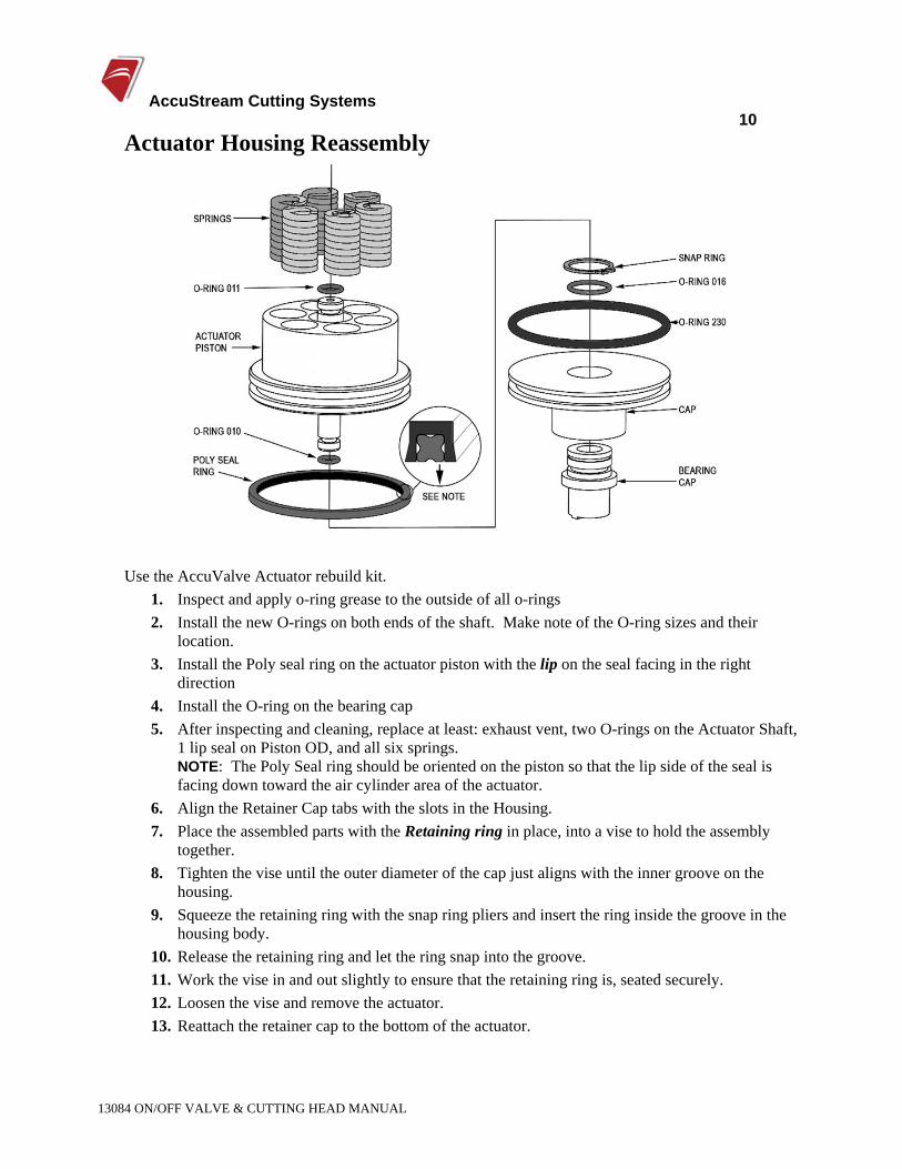
Actuator Housing Reassembly
Use the AccuValve Actuator rebuild kit. 1. Inspect and apply o-ring grease to the outside of all o-rings 2. Install the new O-rings on both ends of the shaft. Make note of the O-ring sizes and their
location. 3. Install the Poly seal ring on the actuator piston with the lip on the seal facing in the right
direction 4. Install the O-ring on the bearing cap 5. After inspecting and cleaning, replace at least: exhaust vent, two O-rings on the Actuator Shaft,
1 lip seal on Piston OD, and all six springs. NOTE: The Poly Seal ring should be oriented on the piston so that the lip side of the seal is facing down toward the air cylinder area of the actuator.
6. Align the Retainer Cap tabs with the slots in the Housing. 7. Place the assembled parts with the Retaining ring in place, into a vise to hold the assembly
together. 8. Tighten the vise until the outer diameter of the cap just aligns with the inner groove on the
housing. 9. Squeeze the retaining ring with the snap ring pliers and insert the ring inside the groove in the
housing body. 10. Release the retaining ring and let the ring snap into the groove. 11. Work the vise in and out slightly to ensure that the retaining ring is, seated securely. 12. Loosen the vise and remove the actuator. 13. Reattach the retainer cap to the bottom of the actuator.
AccuStream Cutting Systems 11
13084 ON/OFF VALVE & CUTTING HEAD MANUAL
Cutting Heads The AccuValve may be used with either the DiaLine or A2 cutting head. The other options available include the carbide and rubber splashguards, water nuts, alternative adapters, ruby and diamond orifices, and many different nozzle sizes. Consult the Valve/Head option drawing for specific part numbers. The key to effective operation is eliminating contamination above the orifice. Proper flushing and rinsing will maximize orifice life. Areas upstream from the orifice should be flushed and washed with water to eliminate any particles that can damage the orifices.
Caution: Verify that there is no water pressure in the valve before making any changes to the valve or its components.
4.5 DiaLine Cutting Head The DiaLine Cutting Head is normally used with diamond orifices for improved cutting performance and superior life. Ruby orifices are also available. A new feature of the DiaLine cutting head is that the diamond orifice and mixing chamber are replaceable. The Nozzle Nut provides an additional alignment to the nozzle and helps in the removal of the nozzle if it is broken.
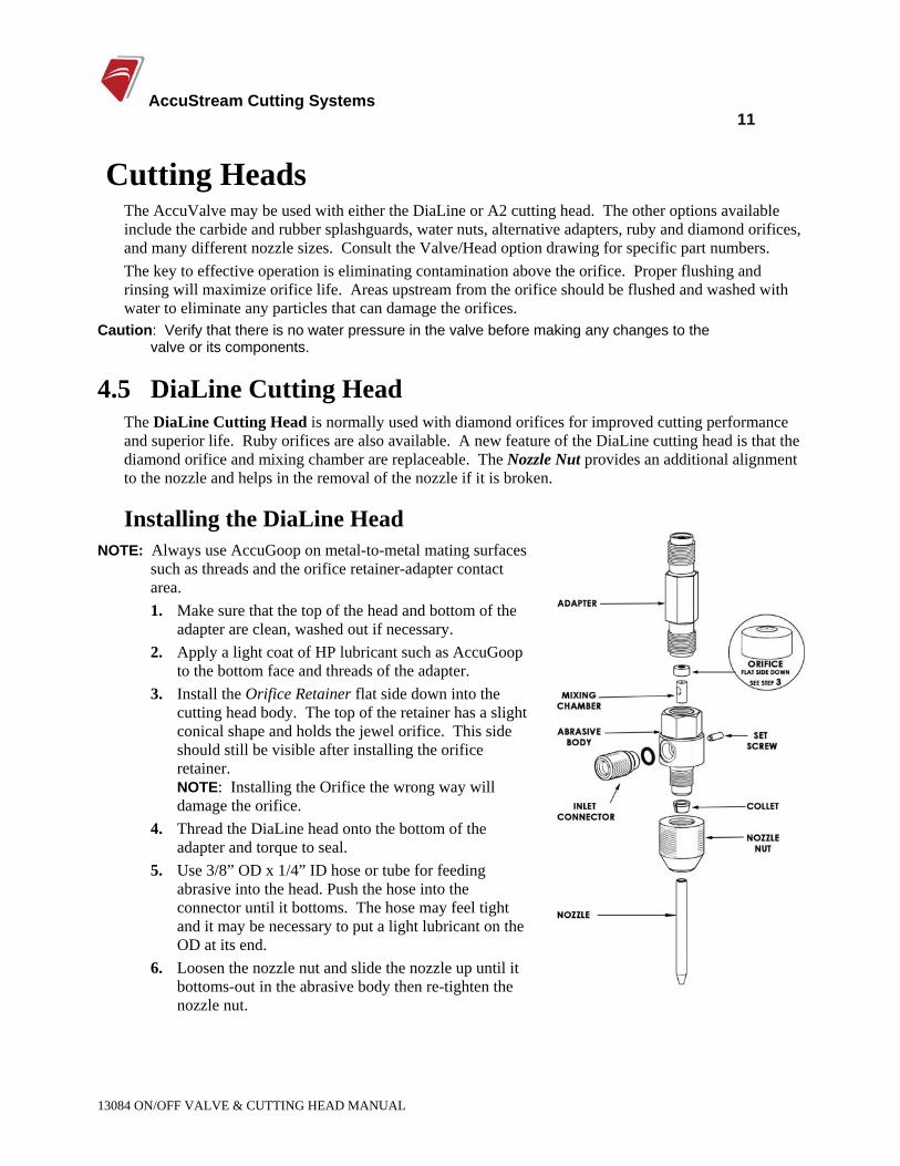
Installing the DiaLine Head NOTE: Always use AccuGoop on metal-to-metal mating surfaces
such as threads and the orifice retainer-adapter contact area. 1. Make sure that the top of the head and bottom of the
adapter are clean, washed out if necessary. 2. Apply a light coat of HP lubricant such as AccuGoop
to the bottom face and threads of the adapter. 3. Install the Orifice Retainer flat side down into the
cutting head body. The top of the retainer has a slight conical shape and holds the jewel orifice. This side should still be visible after installing the orifice retainer. NOTE: Installing the Orifice the wrong way will damage the orifice.
4. Thread the DiaLine head onto the bottom of the adapter and torque to seal.
5. Use 3/8” OD x 1/4” ID hose or tube for feeding abrasive into the head. Push the hose into the connector until it bottoms. The hose may feel tight and it may be necessary to put a light lubricant on the OD at its end.
6. Loosen the nozzle nut and slide the nozzle up until it bottoms-out in the abrasive body then re-tighten the nozzle nut.
AccuStream Cutting Systems 12
13084 ON/OFF VALVE & CUTTING HEAD MANUAL
Replacing the Mixing Chamber The Mixing Chamber may require replacement after extended use. When the hole through the mixing chamber exceeds .090 it should be replaced.
Removing the worn mixing chamber. 1. Remove the DiaLine Head from the Adapter. 2. Remove the orifice retainer, inlet connector, nozzle nut, and collet from the body. Unthread the
setscrew by a few turns that holds the mixing chamber. 3. Push the mixing chamber up and out the top of the body with a .250 dia. pin.
Installing the new mixing chamber. 1. The mixing chamber must be installed with the top of the chamber flush to the top of the bore. 2. Place the orifice retainer in the bore with the cone side up and hold it down with a finger. 3. Slide the new mixing chamber into the body up from the bottom until it is touching the bottom
of the orifice retainer and align the abrasive inlet hole of the chamber with the inlet hole of the abrasive body.
4. Tighten the set screw to secure the mixing chamber. 5. Reassemble the DiaLine head and thread the head back on the adapter.
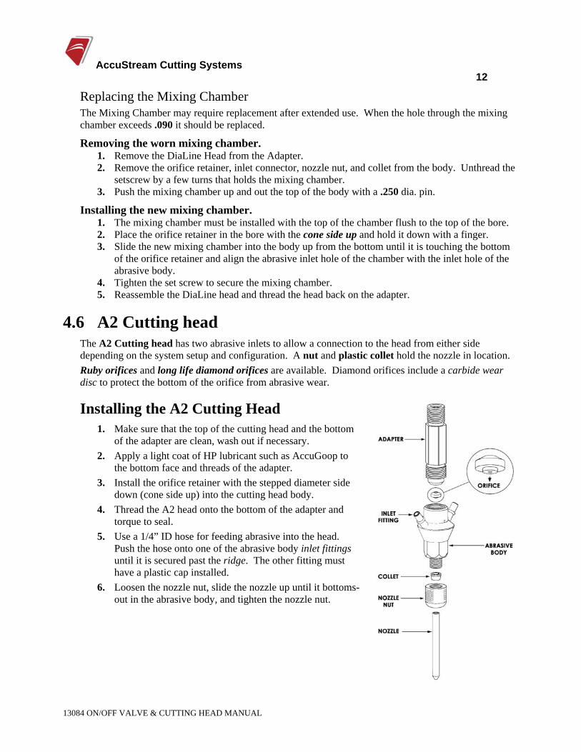
4.6 A2 Cutting head The A2 Cutting head has two abrasive inlets to allow a connection to the head from either side depending on the system setup and configuration. A nut and plastic collet hold the nozzle in location. Ruby orifices and long life diamond orifices are available. Diamond orifices include a carbide wear disc to protect the bottom of the orifice from abrasive wear.
Installing the A2 Cutting Head 1. Make sure that the top of the cutting head and the bottom
of the adapter are clean, wash out if necessary. 2. Apply a light coat of HP lubricant such as AccuGoop to
the bottom face and threads of the adapter. 3. Install the orifice retainer with the stepped diameter side
down (cone side up) into the cutting head body. 4. Thread the A2 head onto the bottom of the adapter and
torque to seal. 5. Use a 1/4” ID hose for feeding abrasive into the head.
Push the hose onto one of the abrasive body inlet fittings until it is secured past the ridge. The other fitting must have a plastic cap installed.
6. Loosen the nozzle nut, slide the nozzle up until it bottoms-out in the abrasive body, and tighten the nozzle nut.
AccuStream Cutting Systems 13
13084 ON/OFF VALVE & CUTTING HEAD MANUAL
4.7 Replaceable Parts Nozzle The nozzle inner diameter wears from the top down. Nozzle life is a function of the orifice size used, quantity and type of abrasive used, and operating pressure. In the A2 head, it is recommended to rotate the nozzle 120 degrees each 8 hours of operation to even the wear on the inside of the nozzle. A list of readily available nozzles, are given below:
OrificeThe most commonly used orifices are, made from either clear or red sapphire (ruby). Ruby orifices are economical and can be used for a reasonable period providing the water quality is good. When a sapphire or ruby orifice shows a bad stream it is usually caused by small microscopic chips at the hole and it should be discarded and replaced. Using blown orifices may wear out the area of the abrasive body where the abrasive mixes with the water stream. Diamond orifices are also available if longer life is necessary. When diamond orifices give a bad stream they can often be fixed by cleaning them in an ultrasonic cleaner.
Handling: The diamond orifice assembly is held in a precision pilot cavity. Sometimes the diamond orifice may stick inside the abrasive head. Stuck orifices can be removed from the head by blowing shop air in the side abrasive inlet port.
Filtration: The 12533 Thimble Filter in-line filter, (optional) is strongly recommended to protect the orifice from larger particulates in the water. The assembly threads into the valve body just above the head and helps to protect the orifice from any damage. If in-line filters are not used it is imperative that the high-pressure lines be purged after any work on the pump or HP plumbing.
Clearing Plugged Nozzles Plugged nozzles can be cleared by turning the nozzle upside down and carefully loading it up into the head and turning the jet on and off.
Adapter (Nozzle Tube) After repeated use, the bottom surface of the adapter where it seals against the orifice retainer may become damaged. Applying AccuGoop to the top of the retainer will reduce or eliminate this problem.
Exterior abrasion Repeated piercing can damage parts exposed to the bounce-back of the jet. A rubber shield that can slide onto the nozzle can be used for protection. These rubber shields can be purchased from Accustream or they can be cut out with the waterjet. There are two optional wear shields available. Part number 11361 is a rubber only guard and 11362 has a carbide faceplate applied to the rubber shield for extreme wear situations.
AccuStream Cutting Systems 14
13084 ON/OFF VALVE & CUTTING HEAD MANUAL
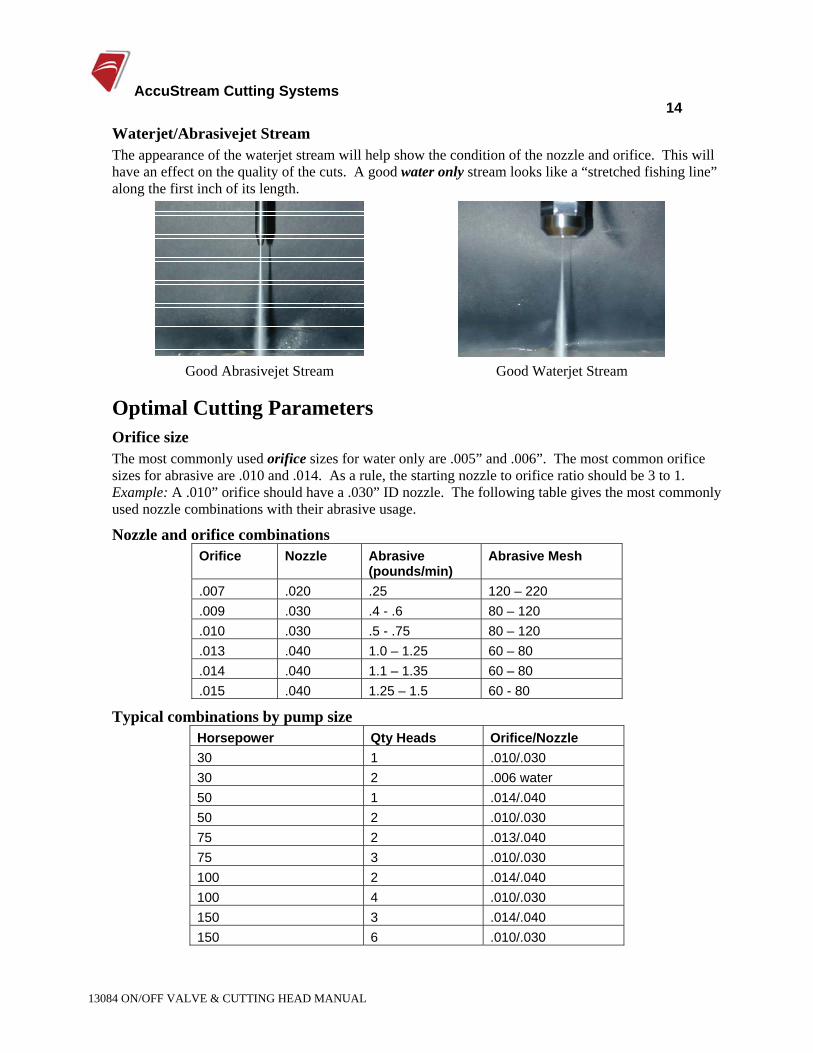
Waterjet/Abrasivejet Stream The appearance of the waterjet stream will help show the condition of the nozzle and orifice. This will have an effect on the quality of the cuts. A good water only stream looks like a “stretched fishing line” along the first inch of its length.
Good Abrasivejet Stream Good Waterjet Stream
Optimal Cutting Parameters Orifice size The most commonly used orifice sizes for water only are .005” and .006”. The most common orifice sizes for abrasive are .010 and .014. As a rule, the starting nozzle to orifice ratio should be 3 to 1. Example: A .010” orifice should have a .030” ID nozzle. The following table gives the most commonly used nozzle combinations with their abrasive usage.
Nozzle and orifice combinations Orifice Nozzle Abrasive
(pounds/min) Abrasive Mesh
.007 .020 .25 120 – 220
.009 .030 .4 - .6 80 – 120
.010 .030 .5 - .75 80 – 120
.013 .040 1.0 – 1.25 60 – 80
.014 .040 1.1 – 1.35 60 – 80
.015 .040 1.25 – 1.5 60 - 80
Typical combinations by pump size Horsepower Qty Heads Orifice/Nozzle 30 1 .010/.030 30 2 .006 water 50 1 .014/.040 50 2 .010/.030 75 2 .013/.040 75 3 .010/.030 100 2 .014/.040 100 4 .010/.030 150 3 .014/.040 150 6 .010/.030
AccuStream Cutting Systems 15
13084 ON/OFF VALVE & CUTTING HEAD MANUAL
4.8 Troubleshooting
Cutting Head Problem Solution
Not flushing thoroughly when changing orifice Bad water quality
Orifices do not last at least 20 hours
Blown in-line filter upstream
In the A2 head rotate nozzle 120° every shift or 8 hours Using too much abrasive.
Nozzle Life too short or not wearing round
Running with worn orifice. Vacuum leak, check inlet tube connection Abrasive not drawing into head
properly Smaller combinations such as .007/.020 may need to have the nozzle lowered about ¼” to induce more vacuum
Can’t unplug nozzle Put nozzle upside down in head and cycle jet on/off
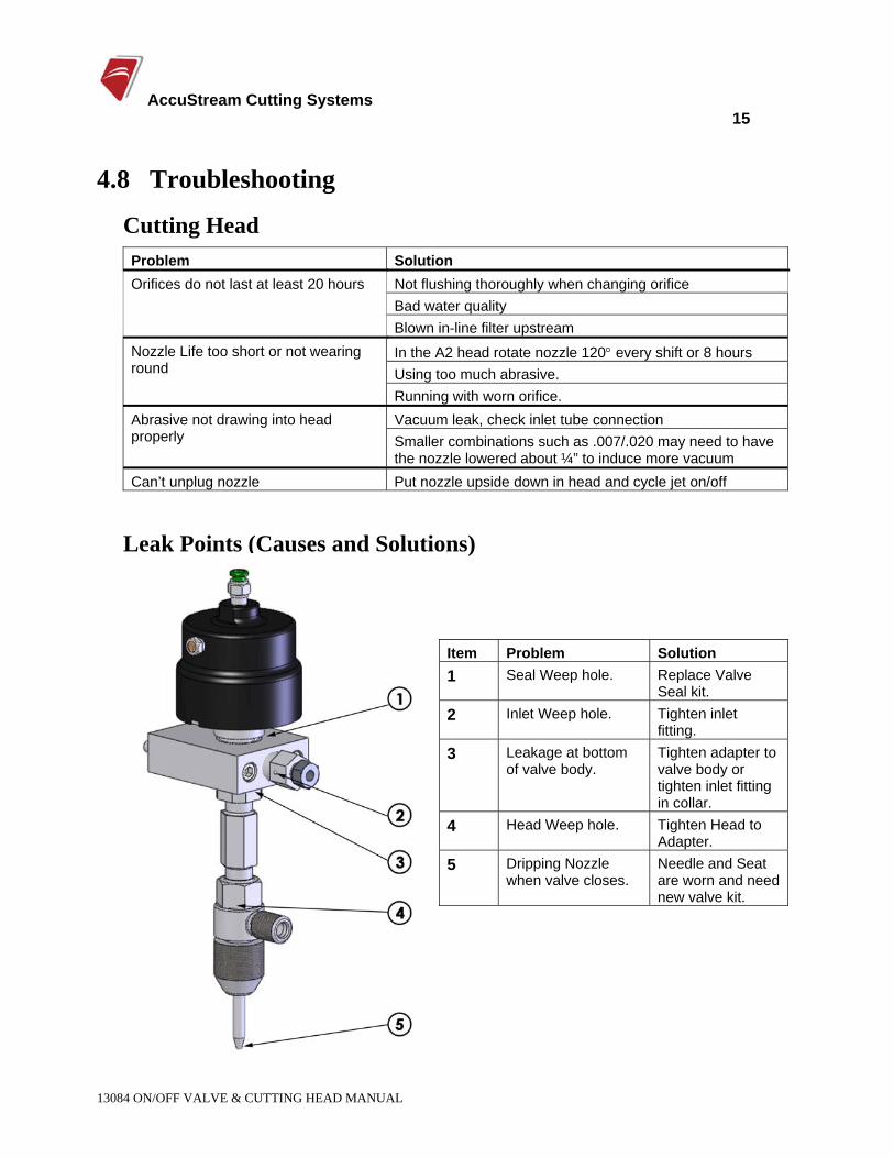
Leak Points (Causes and Solutions)
Item Problem Solution 1 Seal Weep hole. Replace Valve
Seal kit. 2 Inlet Weep hole. Tighten inlet
fitting. 3 Leakage at bottom
of valve body. Tighten adapter to valve body or tighten inlet fitting in collar.
4 Head Weep hole. Tighten Head to Adapter.
5 Dripping Nozzle when valve closes.
Needle and Seat are worn and need new valve kit.
AccuStream Cutting Systems 16
13084 ON/OFF VALVE & CUTTING HEAD MANUAL
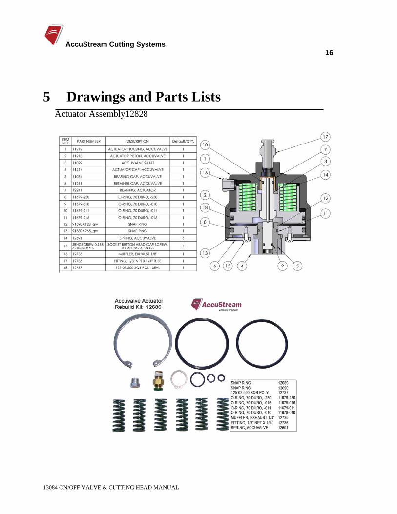
5 Drawings and Parts Lists Actuator Assembly12828
AccuStream Cutting Systems 17
13084 ON/OFF VALVE & CUTTING HEAD MANUAL
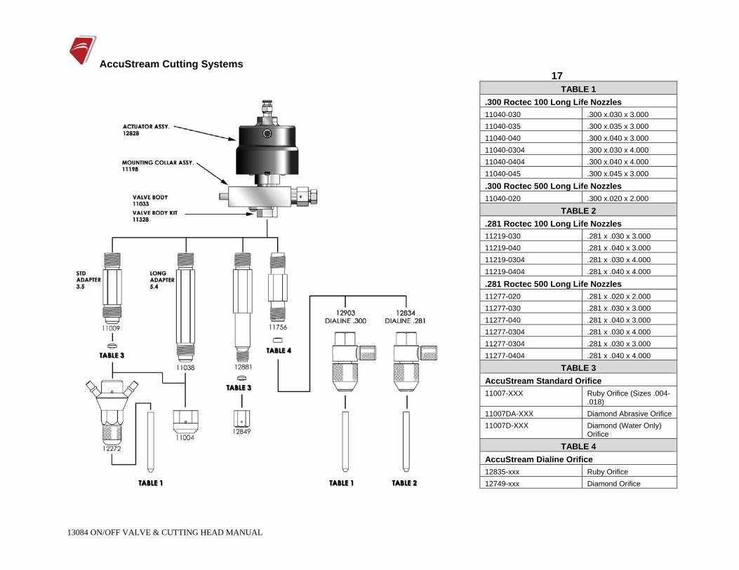
TABLE 1 .300 Roctec 100 Long Life Nozzles 11040-030 .300 x.030 x 3.000 11040-035 .300 x.035 x 3.000 11040-040 .300 x.040 x 3.000 11040-0304 .300 x.030 x 4.000 11040-0404 .300 x.040 x 4.000 11040-045 .300 x.045 x 3.000
.300 Roctec 500 Long Life Nozzles 11040-020 .300 x.020 x 2.000
TABLE 2 .281 Roctec 100 Long Life Nozzles 11219-030 .281 x .030 x 3.000 11219-040 .281 x .040 x 3.000 11219-0304 .281 x .030 x 4.000 11219-0404 .281 x .040 x 4.000
.281 Roctec 500 Long Life Nozzles 11277-020 .281 x .020 x 2.000 11277-030 .281 x .030 x 3.000 11277-040 .281 x .040 x 3.000 11277-0304 .281 x .030 x 4.000 11277-0304 .281 x .030 x 3.000 11277-0404 .281 x .040 x 4.000
TABLE 3 AccuStream Standard Orifice 11007-XXX Ruby Orifice (Sizes .004-
.018) 11007DA-XXX Diamond Abrasive Orifice 11007D-XXX Diamond (Water Only)
Orifice
TABLE 4 AccuStream Dialine Orifice 12835-xxx Ruby Orifice 12749-xxx Diamond Orifice

AccuStream Cutting Systems
13084 ON/OFF VALVE & CUTTING HEAD MANUAL