Embed Size (px)
Citation preview
OperationsManual
Models: 3700 PRO | 6700 MAX

TABLE OF CONTENTS
IMPORTANT SAFEGUARDS AA
TABLE OF CONTENTS 01STATEMENTS & SYMBOLS 02INTRODUCTION 02
General 02Intended Use 02Contradiction 02
SYSTEM COMPONENTS 03PRODUCT FUNCTIONS 04
Pump Unit 04Mattress System 04
INSTALLATION 06GROUNDING INSTRUCTIONS 07OPERATION 08
General 08CPR Function 11Pressure Set Up 11Low Pressure 11
CLEANING 12Pump Unit 12Mattress System 12
HANDLING & STORAGE 13MAINTENANCE 13
General 13Low Pressure 13
TROUBLESHOOTING 14SPECIFICATIONS 14
1

Statements & SymbolsNote, Caution, Warning & Danger Statements
NOTE
Indicates some tips of some information users should be aware of.
CAUTION
Indicates correct operating or maintenance procedure in order to prevent damage to or destructionof the equipment or other property.
WARNING/DANGER
Calls attention to a potential danger that requires correct procedures or practices in order to prevent personal injury.
Others
Symbols on the printed label on the outside of the package box are as follows:
Grounding Terminal Attention! Read All Instructions First!
INTRODUCTIONThis Manual should be used for the initial set up of the system and for reference purposes.
General
The enclosed control unit is designed to run a pressure redistribution mattress. Certain models may also be equipped to deliver low air loss therapy. The control unit has been tested and certified to the following standards:
UL 60601 CE
FDA
Intended Use
This system is intended to provide pressure redistribution to treat staged ulcers and/or reduce the incidence of pressure ulcers while optimizing patient comfort in any care setting.
Contradiction
Patient conditions for which the application of pressure redistribution therapy on an alternating system is contraindicated as follows.
Cervical or skeletal traction Unstable spinal cord injuries
2
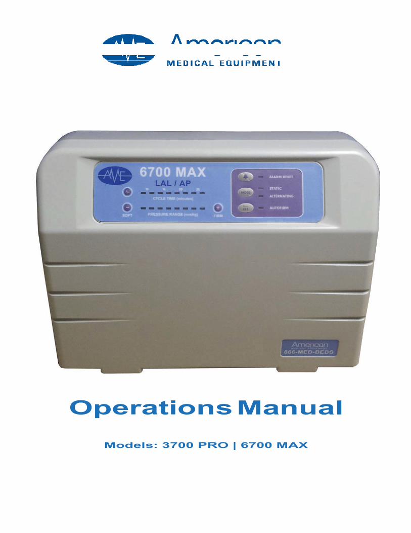
SYSTEM COMPONENTS
Typical system setup includes a pump unit, mattress and operations manual. If the pump unit or mattress are missing or damaged, please contact American Medical Equipment for replacement.
Pump Unit
Identify the pump style ordered forfunctions and options.
Mattress
Most mattress systems containcover assembly, base cover,manifold and air cells. Otheritems may be optional.
Manual
Always read the manual before using any medical product
3

PRODUCT FUNCTIONS
Pump Unit*
The functions of the pump units are described below. Please refer to the figures of each type.
..,.. Power switch:
The switch is on the right side of the unit.Turn ON/OFF the power, the unit will start/stop operation.
Pressure-selector knob:
Turn the knob from the soft to firm position to select a pressure value
Pressure-selector touch pad:
There are seven pressure levels on the touch panel, providing options of pressure value.
Normal Pressure LED:
Indicates the pressure has reached the set level.
Low Pressure LED:
Indicates the pressure is below the set level. The alarm will turn on at the same time.
Cycle Time-selector touch panel:
Select a desired alternating cycle time from the touch panel.The cycle time value can be 10, 15, 20 or 25 minutes.There are two LEDs for each time value.
Alarm Reset:
The alarm will turn on when the Low Pressure LED is on.To mute the alarm, simply press the reset button. The alarm LED will flash.Re-Press the reset button to reactivate the audible alarm.
Static I Alternating Control:
Sets the air mattress in static mode or alternating mode.
Auto Firm:
Sets the air mattress to auto inflation mode.
*Your controller may or may not include all of the functions listed.
Mattress System
American Medical Equipment offers many different mattress surface options for use with either the 3700 PRO or 6700 MAX. Configurations may vary in function, size, materials, and optional safety features.
4

3700 PRO
Manually Controlled Alternating Pressure Controller
6700 MAX
Micro Processor Controlled Alternating Pressure Controller
Power switch Pressure selector knob Normal pressure LED Low pressure LED Alarm reset button Static Control button
Power switch Pressure selector touch pad Cycle time selector touch panel Alarm reset button
Static/Alternating control button Auto Firm
5

II
INSTALLATION
Step 1
Step 2
Step 3
Step 4
Step 5
Step 6
Step 7
Place mattress flatly on the bed frame. The inflation tube should be towards the foot end. See (sample) figure below.
Cover with a cotton sheet to avoid direct skin contact & reduce friction (not included).
Hang the pump unit on the foot end of the bed frame and make sure that it is stable.
.Connect the inflation tubes from the mattress to the controller's inflation ports. Make sure they are properly attached and not leaking.
NOTE:
Make sure the air hoses are not kinked or tucked under the mattress.
Also check to ensure the CPR valve is properly attached.
.Plug the power cord into an electrical outlet with grounded AC power. This productshould be grounded. The power cord has a grounding wire with a grounding pin.The three wire plug must be plugged properly into an outlet and grounded as shown in the Grounding Instructions section.
NOTE:
Before inserting the plug into the outlet, make sure the voltage is
compatible. Also make sure this product is well grounded.
Turn on the power by pressing the power switch on the right side of the control unit.Proceed to the Operation Section
Make sure to disconnect the control unit by unplugging the power cord when it is not in use.
6

II
GROUNDING INSTRUCTIONS
This product is for use on a nominal 120V circuit and should be grounded. In the event of anelectrical short circuit, grounding reduces the risk of electrical shock by providing an escape wire forthe electrical current. This product is equipped with a cord that contains a grounding wire with agrounding plug.
DANGER- Improper use of the grounding plug can result in a risk of electrical shock.
If repair or replacement of the cord is necessary, do not connect the grounding to either flat bladeterminal. The wire with insulation having an outer surface that is green with or without yellow stripe is the grounding wire.
Check with a qualified electrician or serviceman if the grounding instructions are not completelyunderstood, or if in doubt as to whether the product is properly grounded.
This product has a grounding plug that looks like the plug illustrated in figure A below. A temporary adapter, which looks like the adapter illustrated in figure B and C may be used to connect this plugto a 2-pole receptacle as shown in figure B if a properly grounded outlet is not available. The temporary adapter should be used only until a properly grounded outlet (figure A) can be installed by a qualified electrician. The green colored rigid ear, lug, tab or the like extending from the adaptermust be connected to a permanent ground such as a properly grounded outlet box cover.Whenever the adapter is used, it must be held in place by the screw.
If it is necessary to use an extension cord, use only a three wire extension cord that has a threeblade grounding plug and a 3-Slot receptacle that will accept the plug on the product. Replace orrepair if damaged.
Grounded outletAdapter
Fig B
Grounded outlet box Grounding pin
Fig. A
Tab for grounding screw
Fig. C
7

II
OPERATION
NOTE:
Always read the operating instructions before use.
General Guidelines for Use:
This product is designed to provide patients with advanced pressure redistribution, used commonly in either the prevention and/or treatment of Stage I-IV ulcers. Make certain to operate this product in a proper way to optimize its value. General information for users to be aware of include:
For products:
For patients:
Hand Check:
DO NOT use another pump with different specifications. It is dangerous to use apump with a pressure capacity greater than 120mmHg. This may result in air cellfailures. DO NOT change any component by yourself. If there is a need for replacement or repair, please contact American Medical Equipment.
When the Normal Pressure LED (green) comes on to indicate the pressure isadjusted to a desired firmness, the patient can then lie on the mattress. Pleasecover the mattress with a cotton sheet to avoid direct skin contact and for the patients comfort (not included). A firm surface will make it easier for the patient to transfer or reposition. Make use of the static mode function. It can support the patient by keeping the mattress from bottoming out when the patient is in a sitting position. See figure below.
Check to see if a suitable pressure is selected by sliding on hand between the airmattress and foam base (or bed frame if there is no foam base) to feel the patient's buttock.Users should be able to feel the space in between, and the acceptable range isapproximately 25 to 40 mm (1" to 1.5"). This hand check procedure is issued byAHCPR.
8

II
MODEL 3700 PRO
Step 1 Turn on the power. The power and Low Pressure LED will come on. The control unit starts to pump air into the mattress.
The alarm will beep and it's LED will come on to alert that pressure is low. Press theAlarm Reset button to mute the alarm, and it's LED will continue to flash.
Step 2 When the pressure reaches the preset level by factory default, the normal pressure LED will come on, and the Low Pressure LED (and the alarm) will turn off.
If the Low Pressure LED (and the alarm) doesn't go off, please contact American Medical Equipment for equipment examination.
Note:
During normal operation, there may be a leakage when the Low Pressure LED
comes on or the alarm sounds. Please refer to the troubleshooting section.
Step 3 Turn the pressure-selector knob to adjust the pressure from the soft to firm position.(approximate pressure range is 20 to 50 mmHg)
N Note:
For suitable pressure, please refer to the previously described
hand check procedure.
Step 4 The unit is preset in alternating mode and it's cycle time is set at 10 min / 60Hz or12min / 50Hz
Press the static button to set it in static mode, and the Static LED will come on. Thepump will enter static mode after it completes the last alternating cycle time. Press the static button again to restart the alternating function.
Note:
Press the static mode button from the touch panel to provide a firm surface that
makes it easier for the patient to transfer or reposition. The static mode can
support the patient by keeping the mattress from bottoming out when the patient
is in the sitting position.
9

II
MODEL 6700 MAX
Step 1 Turn on the power. A beep sound will begin the operation.
Step 2 These two types will enter a static mode initially when the power is turned on. First itwill inflate the mattress to approximately 30mmHg and then enter the alternating mode.
If 30 mmHg cannot be reached within 30 minutes, the unit will stay in static mode andkeep inflating. If 30mmHg still cannot be reached within another 15 minutes, the alarmwill beep and it's LED will come on.
Press the Alarm Reset button to mute the alarm. The Alarm LED will flash. Press theAlarm Reset button again to have the audible alarm and Alarm LED on again.
Step 3 The alternating cycle time and the pressure level are present to the middle settings.Select from the touch panel to adjust the cycle time and pressure level.
Press the static button to set it in static mode, and the static LED will come on. Thepump will enter static mode after it completes the last alternating cycle time. Press the Static Button again to restart the alternating function.
Note:
Press the static mode button from the touch panel to provide a firm surface that
makes it easier for the patient to transfer or reposition. The static mode can
support the patient by keeping the mattress from bottoming out when the patient
is in the sitting position.
Step 4 During normal operation, the unit will monitor pressure. If the pressure is lower than aset pressure, the controller will automatically inflate the mattress to the set pressurelevel and then stop. The alarm will beep and it's LED will come on to alert a low pressure condition.
Press the Alarm Reset button to mute the alarm. The Alarm LED will flash. Press theAlarm Reset button again to have the audible alarm and Alarm LED on again.
Setp 5 Press the Auto Firm button to automatically inflate the mattress to the maximum level(above 70mmHg) for about 30 minutes. The pressure will return to a previously setlevel after 30 minutes.
In case there is a bad connection of tubing or any air leakage from the mattress, thiswill result in a low pressure condition, and it will activate the alarm.
Note:
For suitable pressure, please refer to the described hand check procedure.
10

II
CPR FUNCTION
When there is an emergency to perform CPR on the patient, pull the CPR valves immediately to release the air quickly from the mattress
CPR Valves can be located on the front right hand side of the mattress or at the foot end.
Pressure Set-Up
Users can adjust the pressure value of the air mattress to a desired firmness by themselves oraccording to the suggestion from the health care professional.
NOTE:
It is recommended to set the pressure-selector knob to Firm or press Auto-Firm on
the touch panel each time the mattress is first inflated. Users can easily adjust the
air mattress to a desired firmness according to the patient's weight and comfort.
Low Pressure
When abnormal pressure occurs, the Low Pressure LED will come on. For some types ofcontrollers, the alarm will be activated to alert of a low pressure condition. Check if the connectionsare secure and correctly installed according to the relevant instructions.
NOTE:
If the pressure is consistently low, check for any leakage (tubes or connecting
hoses). If necessary, contact American Medical Equipment’s Customer Service
Department at (866) 233-6337 to replace damaged tubes or hoses.
11

II
CLEANINGIn this section, we describe the procedures to clean and decontaminate the control unit. It isimportant to follow the procedures before using the system on patients.
Control Unit
DO NOT immerse or soak the pump unit. Check for external damage and move the controller to a designated cleaning area. Place the controller on a work surface and wipe the outside of the case with quaternary
ammonium solution. Allow the solution to incubate for 10 minutes or accordingly as stated by the cleaning product used.
DO NOT spray and cleaning solution directly on the surface on the controller. DO NOT use Hypo-carbonate or Phenolic based cleaning solution as this may cause damage to
the case. Wipe case with a clean cloth. Make sure all areas are clean (top, bottom and both sides).
Spray cloth with cleaning solution and clean faceplate or control panel. DO NOT use excesscleaning solution on faceplate or control panel. (If solution gets inside, DAMAGE will occur.
Allow all surfaces to dry completely after cleaning. After pump id thoroughly cleaned and dried, proceed to plug in the controller and test to make
sure it is running properly. Inspect and clean or replace filter if soiled or clogged.
Mattress
Brush off or wipe down all surfaces of the cover with soap and water before wetting with any liquid disinfectant.
Any obvious blood spots should be soaked thoroughly with 1:9 Hypochlorite solution (1 part bleach to 9 parts water) and allow drying for at least 10 minutes. Then blot with a clean, damp cloth.
Unzip the top cover from the mattress. Brush or wipe down all surfaces with soap and water before applying any liquid. Covers are immersed and soaked in disinfectant for the required incubation time. After pre soaking, the cover is rinsed through a regular cycle in a washer with no
soap then laundered with mild detergent. (Wash temperature 93°F, rinsetemperature 78°F or the coldest setting).
Covers are aerated until they are fully dry. (Drying temperature range 90°F -120°F or on the coldest setting)
The air cells are unsnapped from one side and are sprayed on all sides with a disinfectant. Let the cells sit for the required incubation time and wipe down with a clean cloth. (Make sure to disconnect all the air cells, one by one, and spray the disinfectant on all sides, including all the connecting tubes and hoses. Let it sit for at least 10 minutes.)
If there is a base after you remove all the air cells, the base has to be sprayed down with the disinfectant, inside and outside. Let it sit for the required incubation time and wipe down with a cloth.
Repeat the process with the tubing set: Spray, incubate and then wipe clean. If a carry bag is present clean completely: Spray, incubate and then wipe clean. Dry the mattress on a sunless area after cleaning.
12

II
HANDLING AND STORAGE
Lay mattress out flat. If mattress contains no foam base or foam filled air cells, it may be rolled up to be stored. Do not fold, crease or stack deflated mattresses Unplug the controller and store with proper identification tag. Follow all national requirements to dispose of non-functioning control units.
MAINTENANCEGeneral
Check the power cord and plug to see if there are abrasions or excessive wear. Check the mattress cover for signs of wear or damage. Ensure the mattress cover and tubes are connected together correctly. Plug in the pump unit and check the airflow from the hose connection port. The airflow should alternate between ports every half cycle time. Check the air hoses to see if there are kinks or breaks.
For replacement please contact American Medical Equipment’s Customer Service at (866) 633-2337. Make sure the mattress tubes are well connected. Check the pump unit and make sure both power and power indicator are off when the switch is turned
off.
LOW PRESSUREExamine if there is air leakage between the pump and the mattress connections or from the air mattress tubes: Check connectors between the air mattress and controller. If there is any leakage,
disconnect the fitting and reconnect it. Check the CPR valves. Ensure the outlets are sealed. Check the air connecting tubes. Ensure each single air cell is not broken. Set the pressure-selector knob to firm position. Keep the tubes fully inflated and inspect for air leakage. Check if there is any air leakage from cells. Ensure no leakage occurs. If any leakage occurs, please contact American Medical Equipment.
13

TROUBLESHOOTINGPROBLEMS
The pump does not work.
Incomplete Inflation(Low pressure)
Filter Cleaning
SOLUTIONS
1. Check 1f the plug is inserted firmly into the outlet2. Turn the power switch on again.
If the power LED is ON and the pump still doesn't work, contact your local dealer immediately.If the power LED is OFF, there may be a faulty outlet. Try to connect the power cord to another outlet. If the power LED is still Off, contact a qualified electrician for main power check.
1. For a quick check, adjust the pressure to Firm position.2. Check to see if the tubes connected to the pump are
twisted or there is any leakage occurring. Always keep the tubes straight. Change the tubes if there is any leakage Ensure the CPR valves are closed
Ensure every single cell is not broken
1. A dirty filter may decrease the air flow.2. Wash filter with mild detergent to keep it clean or replace
Check the air filter at the back on the pump unit routinely.
14

Pump Units
SERIES
3700 PRO
6700 MAX
Mattresses
FUNCTION
On/Off SwitchPressure selector knobNormal Pressure LEDLow Pressure LEDStatic function buttonAlarm Reset button
On/Off SwitchPressure selector touch panel Cycle time selector touch panel Static FunctionAlarm Reset buttonAuto Firm
SPECIFICATIONS
Dimension 33.4 x 12.0 x 24.6 em (13.1 x 4.7 x 9.7 in)Power 230V AC/50Hz 120V AC/60HzPressure 10 - 50mmHgCycle Time 12min/50Hz,1Omin/60Hz
Dimension 33.4 x 12.0 x 24.6 em (13.1 x 4.7 x 9.7 in)Power 230V AC/50Hz 120V AC/60HzPressure 1o- 50 (70mmHg Max Inflate)Cycle Time 10,15,20,25 min selectable
MODEL ARRANGEMENT DIMENSION MATERIAL
Protec -- 3580Protec – 4880
8" x 20 cells AP/LAL8" x 20 cells AP/LAL
35" X 80" X 10"48" X 80" X 10"
Nylon/Polyurethane Nylon/Polyurethane
15

System
Item
MedicalEquipment
Class IIPXO AP/APG NOType BF
Applied Part Mattress
Power Supply AC 120V/60Hz,10W 1A
Pressure Range 10 - 50 mmHg for Model 3700 PRO10 -70 mmHg for Model 6700 MAX
Cycle Time 12min/50Hz,10 min/60Hz for Model 3700 PRO10,15,20, 25 min, selectable for Model 6700 MAX
Dimensions 26.0 x 13.0 x 8.0 em10.2 x 5.1 x 3.1inches
Weight 1.5 kg3.31bs.
EnvironmentRequirements
Temperature: OperationStorageShipping
50°F- 95°F59°F-122°F59°F-158°F
Humidity: Operation Storage
20% - 80% non-condensing10% - 90% non-condensing
Safety Standards UL, c-UL, CE
NOTE: The above specifications are also applicable to those areas operating
with the same power supply range.
16

NOTES:
American Medical Equipment v.12.2902
691 Green Crest Dr Westerville OH 43081 (614) 237-1133 • Toll Free (866) 633-2337 Fax (614) 237-1177 www.amemedbeds.com