Embed Size (px)
DESCRIPTION
Modelo de Interacción pórtico Tabique
Citation preview

1
Note: Our intent is that you try this problem on your own first. After you have solved it on yourown, you can step through our solution if desired. If you have problems trying to create themodel, then follow the steps in our solution.
Problem NFrame-Shear Wall Interaction
Concrete Material PropertiesE =3600 ksi, Poissons Ratio = 0.2
FrameBeams: 12” wide by 24” deepColumns: 24” by 24”, pinned base
DiaphragmProvide rigid diaphragm constraint at each level.
To DoDetermine shear carried by wall and by frame at 2nd level and at 6th level.
12’
12’
12’
12’
12’
Roof
6th
5th
4th
3rd
Base
2nd
12’
12' 5' 20' 20' 20'
60 k
50 k
40 k
30 k
20 k
10 k
6” thick concrete shear wall.There are no beams or columnsembedded in the shear wall.

2
Problem N Solution
1. Click the drop down box in the status bar to change the units to kip-ft.
2. From the File menu select New Model From Template…. This displays the ModelTemplates dialog box.
3. In this dialog box click on the Portal Frame template button to display thePortal Frame dialog box.
4. In this dialog box
• Type 6 in the Number of Stories edit box.
• Type 3 in the Number of Bays edit box.
• Accept the default Story Height of 12.
• Type 20 in the Bay Width edit box.
• Click the OK button.
5. Click the “X” in the top right-hand corner of the 3-D View window to close it.
6. From the Draw menu select Edit Grid... to display the Modify Grid Lines dialog box.
7. In this dialog box:
• Verify that the X option is selected in the Direction area.
• Type -35 in the X Location edit box and click the Add Grid Line button.
• Type -47 in the X Location edit box and click the Add Grid Line button.
• Click the OK button. The screen appears as shown in Figure N-1.
8. Click the Quick Draw Rectangular Shell Element button on the side toolbar (orselect Quick Draw Rectangular Shell Element from the Draw menu).
9. Click in the area labeled “A” in Figure N-1 to input the first shell element. Note that aquick Shell element is drawn by clicking in a grid space, bounded by four grid lines.
10. Click in the areas labeled “B”, “C”, “D”, “E” and “F”, in that order, in Figure N-1 to inputthe other shell elements.
11. Click the Pointer button on the side tool bar to exit draw mode and enter select mode.

3
Figure N-1: Screen As It Appears After Step 7
12. Click the Set Elements button on the main toolbar (or select Set Elements… from theView menu) to display the Set Elements Dialog box.
13. In this dialog box:
• Check the Labels box in the Joints area.
• Check the Fill Elements check box.
• Click the OK button.
Note: If the font size is too small for you to read the joint labels use the followingprocedure to increase the font size. From the Options menu select Preferences, clickon the Dimensions Tab if it is not already visible, type in a new (larger) font size in theMinimum Graphic Font Size edit box (usually about 6 points is sufficient), click the OKbutton and then click the Refresh Window button on the main toolbar.
14. Select the joints 41 and 42 at the base of the shear wall.
A
B
C
D
E
F

4
15. From the Assign menu, choose Joint, and then Restraints…from the submenu. This willdisplay the Joint Restraints dialog box.
16. In this dialog box:
• Click the pinned base fast restraint button to set all translational degrees offreedom (U1, U2 and U3) as restrained.
• Click the OK button
17. Click the Show Undeformed Shape button to remove the display of joint restraintsand reset the window display (title).
18. Click the drop down box in the status bar to change the units to kip-in.
19. From the Define menu select Materials... to display the Define Materials dialog box.
20. Click on CONC in the Materials area to highlight (select) it, and then click theModify/Show Material button. The Material Property Data dialog box is displayed.
21. In this dialog box:
• Verify that the Modulus of Elasticity is set to 3600.
• Verify that Poisson’s Ratio is set to 0.2.
• Click the OK button twice to exit all dialog boxes.
22. From the Define menu select Frame Sections... to display the Define Frame Sectionsdialog box.
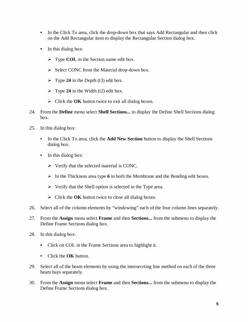
23. In this dialog box:
• In the Click To area, click the drop-down box that says Add I/Wide Flange and thenclick on the Add Rectangular item to display the Rectangular Section dialog box.
• In this dialog box:
À Type BEAM in the Section name edit box.
À Select CONC from the Material drop-down box.
À Type 24 in the Depth (t3) edit box.
À Type 12 in the Width (t2) edit box.
À Click the OK button to return to the Define Frame Sections dialog box.
5
• In the Click To area, click the drop-down box that says Add Rectangular and then clickon the Add Rectangular item to display the Rectangular Section dialog box.
• In this dialog box:
À Type COL in the Section name edit box.
À Select CONC from the Material drop-down box.
À Type 24 in the Depth (t3) edit box.
À Type 24 in the Width (t2) edit box.
À Click the OK button twice to exit all dialog boxes.
24. From the Define menu select Shell Sections... to display the Define Shell Sections dialogbox.
25. In this dialog box:
• In the Click To area, click the Add New Section button to display the Shell Sectionsdialog box.
• In this dialog box:
À Verify that the selected material is CONC.
À In the Thickness area type 6 in both the Membrane and the Bending edit boxes.
À Verify that the Shell option is selected in the Type area.
À Click the OK button twice to close all dialog boxes.
26. Select all of the column elements by “windowing” each of the four column lines separately.
27. From the Assign menu select Frame and then Sections... from the submenu to display theDefine Frame Sections dialog box.
28. In this dialog box:
• Click on COL in the Frame Sections area to highlight it.
• Click the OK button.
29. Select all of the beam elements by using the intersecrting line method on each of the threebeam bays separately.
30. From the Assign menu select Frame and then Sections... from the submenu to display theDefine Frame Sections dialog box.

6
31. In this dialog box:
• Click on BEAM in the Frame Sections area to highlight it.
• Click the OK button.
32. Select all of the joints at the Roof level by “windowing”.
33. From the Assign menu select Joint and then Constraints... from the submenu to displaythe Constraints dialog box.
34. In this dialog box:
• In the Click To area click the drop-down box and select Add Diaphragm to display theDiaphragm Constraint dialog box.
• In this dialog box:
À Type ROOFDIA in the Constraint Name edit box.
À Select the Z Axis option in the Constraint Axis area.
À Click the OK button twice to exit all dialog boxes.
35. Select all of the joints at the 6th level by “windowing”.
36. From the Assign menu select Joint and then Constraints... from the submenu to displaythe Constraints dialog box.
37. In this dialog box:
• In the Click To area click the drop-down box and select Add Diaphragm to display theDiaphragm Constraint dialog box.
• In this dialog box:
À Type 6THDIA in the Constraint Name edit box.
À Select the Z Axis option in the Constraint Axis area.
À Click the OK button twice to exit all dialog boxes.
38. Select all of the joints at the 5th level by “windowing”.
39. From the Assign menu select Joint and then Constraints... from the submenu to displaythe Constraints dialog box.
40. In this dialog box:

7
• In the Click To area click the drop-down box and select Add Diaphragm to display theDiaphragm Constraint dialog box.
• In this dialog box:
À Type 5THDIA in the Constraint Name edit box.
À Select the Z Axis option in the Constraint Axis area.
À Click the OK button twice to exit all dialog boxes.
41. Select all of the joints at the 4th level by “windowing”.
42. From the Assign menu select Joint and then Constraints... from the submenu to displaythe Constraints dialog box.
43. In this dialog box:
• In the Click To area click the drop-down box and select Add Diaphragm to display theDiaphragm Constraint dialog box.
• In this dialog box:
À Type 4THDIA in the Constraint Name edit box.
À Select the Z Axis option in the Constraint Axis area.
À Click the OK button twice to exit all dialog boxes.
44. Select all of the joints at the 3rd level by “windowing”.
45. From the Assign menu select Joint and then Constraints... from the submenu to displaythe Constraints dialog box.
46. In this dialog box:
• In the Click To area click the drop-down box and select Add Diaphragm to display theDiaphragm Constraint dialog box.
• In this dialog box:
À Type 3RDDIA in the Constraint Name edit box.
À Select the Z Axis option in the Constraint Axis area.
À Click the OK button twice to exit all dialog boxes.
47. Select all of the joints at the 2nd level by “windowing”.
8
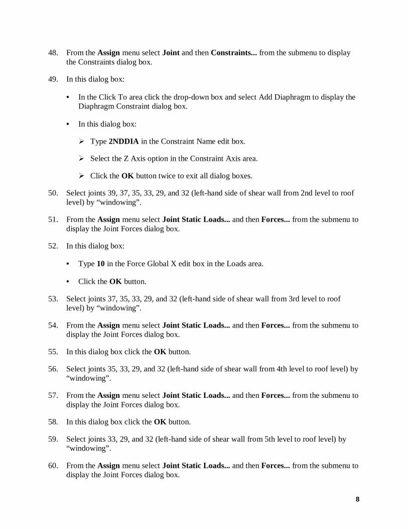
48. From the Assign menu select Joint and then Constraints... from the submenu to displaythe Constraints dialog box.
49. In this dialog box:
• In the Click To area click the drop-down box and select Add Diaphragm to display theDiaphragm Constraint dialog box.
• In this dialog box:
À Type 2NDDIA in the Constraint Name edit box.
À Select the Z Axis option in the Constraint Axis area.
À Click the OK button twice to exit all dialog boxes.
50. Select joints 39, 37, 35, 33, 29, and 32 (left-hand side of shear wall from 2nd level to rooflevel) by “windowing”.
51. From the Assign menu select Joint Static Loads... and then Forces... from the submenu todisplay the Joint Forces dialog box.
52. In this dialog box:
• Type 10 in the Force Global X edit box in the Loads area.
• Click the OK button.
53. Select joints 37, 35, 33, 29, and 32 (left-hand side of shear wall from 3rd level to rooflevel) by “windowing”.
54. From the Assign menu select Joint Static Loads... and then Forces... from the submenu todisplay the Joint Forces dialog box.
55. In this dialog box click the OK button.
56. Select joints 35, 33, 29, and 32 (left-hand side of shear wall from 4th level to roof level) by“windowing”.
57. From the Assign menu select Joint Static Loads... and then Forces... from the submenu todisplay the Joint Forces dialog box.
58. In this dialog box click the OK button.
59. Select joints 33, 29, and 32 (left-hand side of shear wall from 5th level to roof level) by“windowing”.
60. From the Assign menu select Joint Static Loads... and then Forces... from the submenu todisplay the Joint Forces dialog box.
9
61. In this dialog box click the OK button.
62. Select joints29, and 32 (left-hand side of shear wall from 6th level to roof level) by“windowing”.
63. From the Assign menu select Joint Static Loads... and then Forces... from the submenu todisplay the Joint Forces dialog box.
64. In this dialog box click the OK button.
65. Select joint 32 (left-hand side of shear wall at roof level).
66. From the Assign menu select Joint Static Loads... and then Forces... from the submenu todisplay the Joint Forces dialog box.
67. In this dialog box click the OK button.
68. Click the Show Undeformed Shape button to remove the display of joint forces.
69. Click the Set Elements button on the main toolbar (or select Set Elements… from theView menu) to display the Set Elements Dialog box.
70. In this dialog box:
• Check the Labels box in the Frames area.
• Check the Labels box in the Shells area.
• Click the OK button.
71. Select joints 29 and 30 and select shell element 1.
72. From the Assign menu select Group Names… to display the Assign Group dialog box.
73. In this dialog box:
• Type 6THWALL in the Groups edit box.
• Click the Add New Group Name button.
• Click the OK button.
74. Select joints 6, 13, 20 and 27 by clicking on each joint individually and select frame(column) elements 6, 12, 18 and 24 using the intersecting line method.
75. From the Assign menu select Group Names… to display the Assign Group dialog box.
76. In this dialog box:

10
• Type 6THFRAME in the Groups edit box.
• Click the Add New Group Name button.
• Click the OK button.
77. Select joints 39 and 40 and select shell element 5.
78. From the Assign menu select Group Names… to display the Assign Group dialog box.
79. In this dialog box:
• Type 2NDWALL in the Groups edit box.
• Click the Add New Group Name button.
• Click the OK button.
80. Select joints 2, 9, 16 and 23 by clicking on each joint individually and select frame(column) elements 2, 8, 14 and 20 using the intersecting line method.
81. From the Assign menu select Group Names… to display the Assign Group dialog box.
82. In this dialog box:
• Type 2NDFRAME in the Groups edit box.
• Click the Add New Group Name button.
• Click the OK button.
83. Click the Set Elements button on the main toolbar (or select Set Elements… from theView menu) to display the Set Elements Dialog box.
84. In this dialog box:
• Uncheck the Labels box in the Joints area.
• Uncheck the Labels box in the Frames area.
• Uncheck the Labels box in the Shells area.
• Click the OK button.
85. From the Analyze menu select Set Options... to display the Analysis Options dialog box.
• In this dialog box click the Plane Frame XZ Plane button to set theavailable degrees of freedom.

11
• Click the OK button.
86. Click the Run Analysis button to run the analysis.
87. When the analysis is complete check the messages in the Analysis window (there should beno warnings or errors) and then click the OK button to close the Analysis window.
88. From the Display menu select Show Group Joint Force Sums… to display the SelectGroups dialog box.
89. In this dialog box:
• Click on 2NDFRAME to highlight it.
• Hold down the shift key on the keyboard and click on 6THWALL. All of the availablegroups, except the default ALL group should now be highlighted.
• Click the OK button to display the a window with the Group Joint Force Summationstabulated.
Note: Notice the direction of the shear (F-X force) in the shear wall at the 6th level.
• When finished viewing the window click the “X” in its upper right-hand corner to closeit.
Note: If you want to print the group joint force sum tables click on the File menu in theGroup Joint Force Summations widow and select either Print Tables or PrintTables to File….