Embed Size (px)
Citation preview
Çukurova Üniversitesi Mühendislik Mimarlık Fakültesi Dergisi, 32(4), ss. 227-240, Aralık 2017 Çukurova University Journal of the Faculty of Engineering and Architecture, 32(4), pp. 227-240, December 2017
Ç.Ü. Müh. Mim. Fak. Dergisi, 32(4), Aralık 2017 227
Modelling Study on the Geotextile, Geogrid and Steel Strip Reinforced
Slopes
Burak EVİRGEN*1
, Mustafa TUNCAN1, Ahmet TUNCAN
1
1Anadolu Üniversitesi, Mühendislik Fakültesi, İnşaat Mühendisliği Bölümü, Eskişehir
Changing the natural conditions of soil creates unexpected stress increments in slope stability projects,
which are required high amount of soil excavation near the highways and railways or braced cut systems.
Some safety problems can occur during this application under different loading cases. In addition, slope
stability design requires economical solutions. Slope-supporting structures should be designed with most
effective solution according to these signified requirements. A slope stability problem considering deep
excavations in front of the reinforced soils are studied within this study in all its parts, after an extensive
review of the literature. Geotextile (GT), geogrid (GG) and steel strip (SS) reinforcements are used to
increase the stability conditions of slope during both experimental procedure and modelling process with
Plaxis software. Each reinforcement type provided the bearing capacity enhancement and showed that
unique displacement behavior. Therefore, most effective reinforcement member can be chosen in design
procedure and construction phase in the site according to the bearing capacity and displacement
requirements according to presented values.
Keywords: Slope stability, Reinforced slope, Geotextile, Geogrid, Steel strip
Geotekstil, Geogrid ve Çelik Şerit Donatılı Şevlerde Modelleme Çalışması
Öz
Zeminin doğal koşullarının değişmesi, yüksek miktarda hafriyat gerektiren otoyol ve demiryolu kenarları
veya destekli kazılardaki şev stabilitesi projelerinde beklenmedik gerilme artışlarına neden olmaktadır.
Bu işlem sırasında farklı yükleme durumlarında bazı güvenlik sorunları oluşabilmektedir. Ek olarak, şev
stabilitesi tasarımı ekonomik çözüm gerektirmektedir. Şev destek yapıları için bu önemli gereksinimler
göz önünde bulundurularak en efektif tasarım yapılmalıdır. Bu çalışmada; kapsamlı bir literatür
taramasının ardından, donatılı zemin yapısının ön kısmında yer alan derin kazılar dikkate alınarak şev
stabilitesi problemi tüm yönleriyle incelenmiştir. Geotekstil (GT), geogrid (GG) ve çelik şerit (SS)
donatılar, hem deney sürecinde hem de Plaxis yazılımı ile modelleme aşamasında şevin stabilite
koşullarının arttırılması işleminde kullanılmıştır. Her donatı tipi zemin taşıma kapasitesi artışı sağlamış ve
kendine has yer değiştirme davranışı göstermiştir. Dolayısıyla, sunulan değerlere göre taşıma kapasitesi
ve yer değiştirme gereklilikleri doğrultusunda, tasarım işlemi ve sahadaki inşa sürecinde en efektif donatı
elemanı seçilebilecektir.
Anahtar Kelimeler: Şev stabilitesi, Donatılı şev, Geotekstil, Geogrid, Çelik şerit
*Sorumlu yazar (Corresponding author): Burak EVİRGEN, [email protected]
Geliş tarihi: 15.11.2017 Kabul tarihi: 19.12.2017
Modelling Study on the Geotextile, Geogrid and Steel Strip Reinforced Slopes
228 Ç.Ü. Müh. Mim. Fak. Dergisi, 32(4), Aralık 2017
1. INTRODUCTION
Retaining structures are used to support for vertical
or close to vertical and inclined slopes of soil
along the highway, road and railway structures.
They are also used for bridge abutments and
stability of miscellaneous slopes as well. They are
made of reinforced concrete named as cantilever
retaining walls and stone masonry named as
gravity retaining walls, generally. If the height of
retaining walls exceed about 8 m-10 m, counterfort
retaining walls can be constructed within the
purpose of reducing the shear and bending
moments. On the other hand, reinforced earth
structures are used to design foundation and earth
retaining buildings. Reinforced earth is created
with the combination of soil and geosynthetics
such as geotextile, geogrid and geonet type of
materials. Reinforced earth structures are preferred
due to the fast construction, high resistance to
earthquake, relatively high tensile strength,
economic feasibility and aesthetic appearance too.
The first reinforced earth-retaining wall for the
roads was constructed in 1972 in the United States
according to Das [1]. Vidal [2] presented the
concept of systematic analysis and design of
reinforced earth structures. Several reinforced
earth retaining walls were constructed in France
soon after his work. Moreover, geosynthetic
reinforced walls was gaining demand in Northern
America in time due to its specific advantages
according to Bathurst and Simac [3]. Miyata and
Bathurst [4] mentioned that more than 30,000 steel
strip reinforced soil walls have been constructed in
Japan from 1970s to 2012s. These approaches
showed that reinforced soils have been widely
used around the world.
Geosynthetic is defined as a planar product
manufactured from polymeric material used with
soil, rock, earth, or other geotechnical engineering
related material as an integral part of a man-made
project, structure, or system as stated by ASTM
D4439-15a [5]. Geotextile is a permeable
geosynthetic made of textiles that is generally
woven product with different filament properties
and dimensions, too. Geotextile is used with soil
and any other earth like materials within the
purpose of separation, reinforcement, filtration and
drainage applications. While soil is good in
compression, geotextile is good in tension.
Therefore, geotextiles are used in the case of low
strength fine-grained silt and clay type of soils to
eliminate the risk of local tearing under load.
Geotextile has rapid, economical and eco-friendly
usage in many geotechnical areas with vegetation
and extra steel reinforcement, recently. In addition
to this, geogrid is a mesh like material produced
from polymeric materials with variable space and
rib properties according to standards. Besides, steel
strip utilization in soil layers creates a strong
composite matrix against active forces. All of these
reinforcements are used with respect to both
increasing of soil bearing capacity and decreasing
both horizontal and vertical deformations against
failures such as settlement, sliding, overturning,
pullout failure and local or general failures.
2. PREVIOUS STUDIES
The most common study approaches of reinforced
soils are experimental evaluations in the literature.
Juran and Christopher [6] determined the behavior
and failure mechanisms of reinforced soil retaining
walls with geotextile and geogrid materials. Three
different failure mechanisms were observed caused
by sliding or breakage of reinforcement and
excessive facing displacement. DeMerchant et al.
[7] realized experimental plate load tests on
geogrid reinforced lightweight aggregate bed for
the case of underlying foundation area. Subgrade
modulus was presented depending on soil density,
width and location of geogrid reinforcements,
tensile strength of geogrid and number of
reinforced layer. Yıldız [8] realized that the
experimental and analytical study at shallow
foundation which is constructed on geogrid
reinforced soil according to distance between
foundation and slope with 30º angle, number of
reinforcement layers and depth of reinforcement
tests. Bathurst et al. [9] predicted that full-scaled
instrumented soil walls reinforced with bar mat,
welded wire and steel strips depending on the
evaluation of AASHTO simplified method
accuracy. Granular backfills have less than 45º
internal friction angle showed reasonably precision
for steel strip reinforced soil wall design according
Burak EVİRGEN, Mustafa TUNCAN, Ahmet TUNCAN
Ç.Ü. Müh. Mim. Fak. Dergisi, 32(4), Aralık 2017 229
to related study. Palmeira [10] conducted that the
testing techniques are still rough approximations
about the behavior of geosynthetic type of
materials in the field. Lin et al. [11] proved the
effectiveness of grid-rib type of geometry in
geosynthetic reinforcements according to
experimental pull out performances. Indraratna et
al. [12] discussed the beneficial effects of geogrids
on the strength characteristics were evaluated
using large-scale direct shear tests. Latha and
Santhanakumar [13] examined the stronger and
weaker polypropylene biaxial geogrid
reinforcements with rigid and modular concrete
block facing systems on shaking table. Nearly 60%
of vertical deformation decrement was reported
with using 3 layers of geogrid usage. Gonzalez-
Torre et al. [14] evaluated those six different
geosynthetics within the purpose of anti-cracking
agent utilization. It is also effective between soil
layers in terms of interlocking effect that consists
of voids between grid strips and thickness. Suzuki
et al. [15] studied the effect of cement treated soil
as a backfill material behind the reinforced soil
walls under different seismic conditions. Costa et
al. [16] investigated the time dependent
deformations in geotextile reinforced soil walls.
Deformations of geogrid reinforced soil walls
through centrifuge model tests at constant gravity
under the effects of molding water content and
stiffness of the geogrid were presented by
Balakrishnan and Viswanadham [17]. Provision of
stiffer geogrid reinforced soil walls reduced
problems due to the marginal backfills as stated in
study. Xiao et al. [18] studied about some model
tests to understand the effects of the offset distance
and width of footing, the length of geogrid
reinforcement, and connection mode between
geogrid and facing, on the maximum capacity of
strip footings that is located on the reinforced soil
walls. Load - settlement characteristics of coir
geotextiles in various forms were studied by Lal et
al. [19], which were subjected to plate load test.
Al-Rkaby et al. [20] realized the monotonic
drained tests within the aim of determination the
effect of principle stress direction on reinforced
soil samples.
The other important research area of reinforced
soils is in-situ applications. Richardson [21]
presented the detailed information about initial
facing failure of geotextile-reinforced retaining
wall constructed in 1987 in North Carolina, USA.
Kim and Won [22] studied long-term behavior of
geosynthetic reinforced walls (GRS) which are
constructed on weak ground. The maximum
horizontal displacement and shear strain at soil
mass without reinforcement were observed about
2.5 times and 1.4 times greater than GRS walls,
within the results of in-situ application and finite
element modelling, respectively. Stuedlein et al.
[23] studied that 46 m tall steel strip reinforced
earth wall technology near the runways of Seattle -
Tacoma International Airport via real time
geotechnical instrumentations. Yonezawa et al.
[24] described the design and construction of GRS
according to satisfying very high-performance
requirements, a high stability for earthquakes and a
high cost effectiveness, which is higher than the
conventional type soil structures. Liu et al. [25]
observed the pressure and displacement changes of
expansive soil/rock channel slope reinforced with
soil bags under moisture effect within 60 m long
full-scaled project. Soil bags practically eliminated
the water content change of underlying soil
influenced by rainfall or channel flow. In addition,
swelling pressure of expansive soil can be
prevented with overburden pressure of soil bag.
Furthermore, various studies can be found in the
literature about new method proposals, finite
element modelling or economic analysis within the
aim of enhancement of the effectiveness. Saving
money within retaining wall projects may be
possible up to 25% and 85% in 5 m tall and 20 m
tall retaining structures with using reinforced soil
walls, respectively consistent with Jones [26].
Yılmaz and Aklık [27] indicated that the
reinforced concrete retaining wall was more
expensive than both geotextile and geogrid
reinforced walls at the rate of 71% and 24%,
respectively. Allen et al. [28] developed that steel
reinforced soil walls in new design methodology
that is called as K-stiffness method. It is utilizing
about prediction of reinforcement loads more
accurately. Hatami and Bathurst [29] presented the
simulation of full-scaled reinforced soil segmental
retaining walls with different reinforcement types
such as polypropylene, polyester, welded wire
Modelling Study on the Geotextile, Geogrid and Steel Strip Reinforced Slopes
230 Ç.Ü. Müh. Mim. Fak. Dergisi, 32(4), Aralık 2017
mesh in FLAC model. Lin et al. [30] developed a
new version of reinforcement mechanism for
slopes. Pseudo-static approach was used to
reduction of reinforcements. Gu [31] evaluated the
benefits of geogrids in two types of steel wire
mesh and steel bar mesh geogrid reinforced soil
underlying flexible pavements in Abaqus software.
The use of geogrid reinforcement decreases the
deformations within the base and subgrade layers
as well as reduces the vertical deformations on top
of subgrade layer. Damians et al. [32] reported that
compressible bearing pads could be effective in
reducing vertical compression loads in reinforced
soil wall structures with limited to a 16.7 m wall
height and 1.5 m depth of embedment. Yu and
Pradhan [33] realized the numerical study on the
mechanism of geogrid reinforcements with respect
to various parameters. Loading rate and particle
shape were founded as leading factors for geogrid -
soil interaction in discrete element method. Hou et
al. [34] compared the friction, stress distribution
and displacement behaviors of strip and H-V
reinforced soils due to finite element modelling
under vertical loads. H-V reinforcement can be
defined as horizontal strip reinforcement
strengthened with vertical partial plates to improve
of its load bearing capacity. Yu et al. [35] defined
the effects of interface stiffness, soil modulus and
foundation modulus parameters on the steel strip
reinforced earth walls due to linear elastic Mohr
Coulomb constitutive model. Carbone et al. [36]
proposed a new inclined plane test procedure both
static and dynamic conditions for interaction
between soil and geosynthetic reinforcements.
Allen and Bathurst [37] developed existing K-
stiffness method to improve the accuracy of
simplified method. Reinforcement stiffness, facing
stiffness, facing batter, and cohesion of backfill
soil were defined as key variables. Liu [38]
proposed an analytical method to analyze the
reinforcement load and compression of reinforced
soil mass subjected to surcharge load. Analytical
method considered soil nonlinearity, soil dilatancy,
soil reinforcement interaction and end restrictions
of reinforced soil mass. Damians et al. [39]
depicted that Plaxis software could be safely used
for the analysis and design of reinforced soil
structures according to both numerical results and
physical measurements. Gao et al. [40] used the
limit analysis approach to determine the required
strength and length of reinforcement. Three-
dimensional analysis for reinforced soil slopes
gave more conservative results than two-
dimensional analysis.
In this study, slope stability conditions in deep
excavation constructions in front of the retaining
structure were evaluated. Slope models were set up
in the laboratory by considering behavior of
reinforced slopes with geotextile, geogrid and steel
strip reinforcements. Vertical static load is applied
up to the failure for each case. In addition,
analytical model of reinforced slopes was
modelled with Plaxis software under 0.50 kg/cm2
vertical stresses within the scope of slope
simulation under light road load located on the top
corner. Displacement values and failure
mechanisms were determined and compared.
3. THEORETICAL CALCULATIONS
Main design criteria of reinforced soil walls are to
compensate the active forces caused by external
effects or soil in itself. Passive forces are the first
solution of this problem. However, if passive
forces remain incapable during this conflict, extra
retaining structures become a part of activity to
provide safety. The material strength of each
reinforcement members distinguishes during the
design process, unlike the system requirements in
bracing systems such as reinforced concrete
retaining walls, lateral piles, sheet piles, etc. Soil
reinforcements must have enough strength against
tension forces, bending moments or tearing with
respect to related standards for geogrid [41],
geotextile [42] and steel strips [43] as well.
Friction behavior is the most important design
criteria to define the interaction performance
between reinforcement and the soil layers. Main
failure mechanisms must be ensured against
overturning, sliding and bearing capacity. In
addition, long-term stability conditions must be
checked both slope reinforcements and facing
behavior in spite of the fact that negative
possibilities may be caused by natural conditions,
unexpected load parameters and harmful effects on
materials. Common standard and regulations
involve the design methods, construction and
Burak EVİRGEN, Mustafa TUNCAN, Ahmet TUNCAN
Ç.Ü. Müh. Mim. Fak. Dergisi, 32(4), Aralık 2017 231
maintenance about mechanically stabilized earth
walls (MSEW) and reinforced soil slopes (RSS),
and the monitoring of their long-term performance.
MSEW is a generic term that includes reinforced
soil. Reinforced earth indicates a specific
reinforced soil system. Reinforced soil walls
having nearly or almost vertical face inclination
which has 70° to 90° and horizontal rows of the
same length and type of reinforcement that retain a
homogeneous backfill, generally [44]. A minimum
reinforcement length of 0.6 to 0.7H (H = height of
wall at wall face) has been used in most designs of
geosynthetic reinforced soil (GRS) and
geosynthetic mechanically stabilized earth walls
(GMSE) [45].
Sun and Graves [46] listed the design checks as
follows; strength limit states, service limit states
and global stability according to LRFD (Load and
Resistance Factor Design) methodology. Strength
limit states are inclusive of external stability
(limiting eccentricity, sliding, bearing resistance)
and internal stability (tensile and pullout resistance
of reinforcement, structural resistance of face
element and face element connections) checks. In
addition, vertical and horizontal wall movements
are defined as service limit states. In order to check
that global stability, overall and compound
stability must be provided as well. Miyata and
Bathurst [47] compared the reliability of geogrids
pullout models used in Japan in terms of ultimate
limit state.
Reinforced earth walls are generally used for
construction of retaining walls, bridge abutments,
waterfront walls, and so forth. There are three
basic ways to design ties that resist the lateral earth
pressure such as Rankine method, Coulomb force
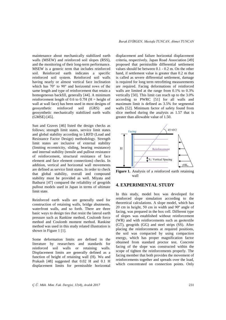
method and Coulomb moment method. Rankine
method was used in this study related illustration is
shown in Figure 1 [1].
Some deformation limits are defined in the
literature by researchers and standards for
reinforced soil walls or retaining walls.
Displacement limits are generally defined as a
function of height of retaining wall (H). Wu and
Prakash [48] suggested that 0.02 H and 0.1 H
displacement limits for permissible horizontal
displacement and failure horizontal displacement
criteria, respectively. Japan Road Association [49]
proposed that permissible differential settlement
values should be between 0.1 - 0.2 m. On the other
hand, if settlement value is greater than 0.2 m that
is called as severe differential settlement, damage
is required for long term retrofitting measurements
are required. Facing deformations of reinforced
walls are limited at the range from 0.1% to 0.3%
vertically [50]. This limit can reach up to the 3.0%
according to PWRC [51] for all walls and
maximum limit is defined as 3.5% for segmental
walls [52]. Minimum factor of safety found from
slice method during the analysis as 1.57 that is
greater than allowable value of 1.50.
Figure 1. Analysis of a reinforced earth retaining
wall
4. EXPERIMENTAL STUDY
In this study, model box was developed for
reinforced slope simulation according to the
theoretical calculations. A slope model, which has
20 cm in height, 50 cm in width and 90º angle of
facing, was prepared in the box cell. Different type
of slopes was established without reinforcement
(WR) and with reinforcements such as geotextile
(GT), geogrids (GG) and steel strips (SS). After
placing the reinforcements at required positions,
the soil was compacted by using compaction
energy, which has proper magnification factor
obtained from standard proctor test. Concrete
facing of the slope was constructed within the
scope of tighten the reinforcements properly. The
facing member that both provides the movement of
reinforcements together and spreads over the load,
which concentrated on connection points. Only
Modelling Study on the Geotextile, Geogrid and Steel Strip Reinforced Slopes
232 Ç.Ü. Müh. Mim. Fak. Dergisi, 32(4), Aralık 2017
experimental part consists of the partially
elaborated study of existing works have been
evaluated by Özdemir et al. [53] and Onur et al.
[54], partially. 4.1. Soil Properties
Clayey sand type of granular fill material was used
as a backfill that has 77.6% sand, 17.8% silt and
4.6% clay. Specific gravity of fill material is 2.67
and the optimum water content is 6.0% obtained
from compaction test. Undrained cohesion and
internal friction angle values were determined as
5.7 kN/m2 and 33.3º, respectively according to the
triaxial test results.
4.2. Reinforcement Properties
Geotextile, geogrid and steel strip reinforcements
are given in Figure 2. 40 mm x 40 mm in square
mesh opening 1.6 mm thick geogrid material has
200 g/m2 planar density. 0.7 mm thick and
8.106 g/m
3 density possessed galvanized steels
have 240 mm in length and 10 mm in width. In
addition, geotextile material has 1.2 mm thickness
and 200 g/m2 planar density values.
Reinforcements were placed 20 mm intervals in
the horizontal direction. All of these dimensions
were calculated by considering real sizes, after the
theoretical calculations within the experimental
frame limits. The average tensile strength values of
reinforcements are taken from manufacturers as
follows; 9.25 kPa, 45 kPa and 515 MPa for GT,
GG and SS, respectively.
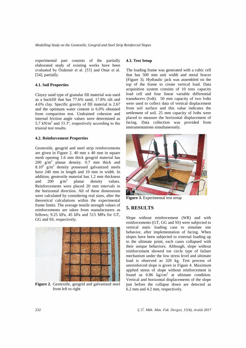
Figure 2. Geotextile, geogrid and galvanized steel
from left to right
4.3. Test Setup
The loading frame was generated with a cubic cell
that has 500 mm unit width and metal braces
(Figure 3). Hydraulic jack was assembled on the
top of the frame to create vertical load. Data
acquisition system consists of 10 tons capacity
load cell and four linear variable differential
transducers (lvdt). 50 mm capacity of two lvdts
were used to collect data of vertical displacement
from soil surface and this value indicates the
settlement of soil. 25 mm capacity of lvdts were
placed to measure the horizontal displacement of
facing. Data collection was provided from
instrumentations simultaneously.
Figure 3. Experimental test setup
5. RESULTS
Slope without reinforcement (WR) and with
reinforcements (GT, GG and SS) were subjected to
vertical static loading case to simulate site
behavior, after implementation of facing. When
slopes have been subjected to external loading up
to the ultimate point, each cases collapsed with
their unique behaviors. Although, slope without
reinforcement showed toe circle type of failure
mechanism under the low stress level and ultimate
load is observed as 320 kg. Test process of
unreinforced slope is given in Figure 4. Maximum
applied stress of slope without reinforcement is
found as 0.86 kg/cm2 at ultimate condition.
Vertical and horizontal displacements of the slope
just before the collapse down are detected as
6.2 mm and 4.2 mm, respectively.
Burak EVİRGEN, Mustafa TUNCAN, Ahmet TUNCAN
Ç.Ü. Müh. Mim. Fak. Dergisi, 32(4), Aralık 2017 233
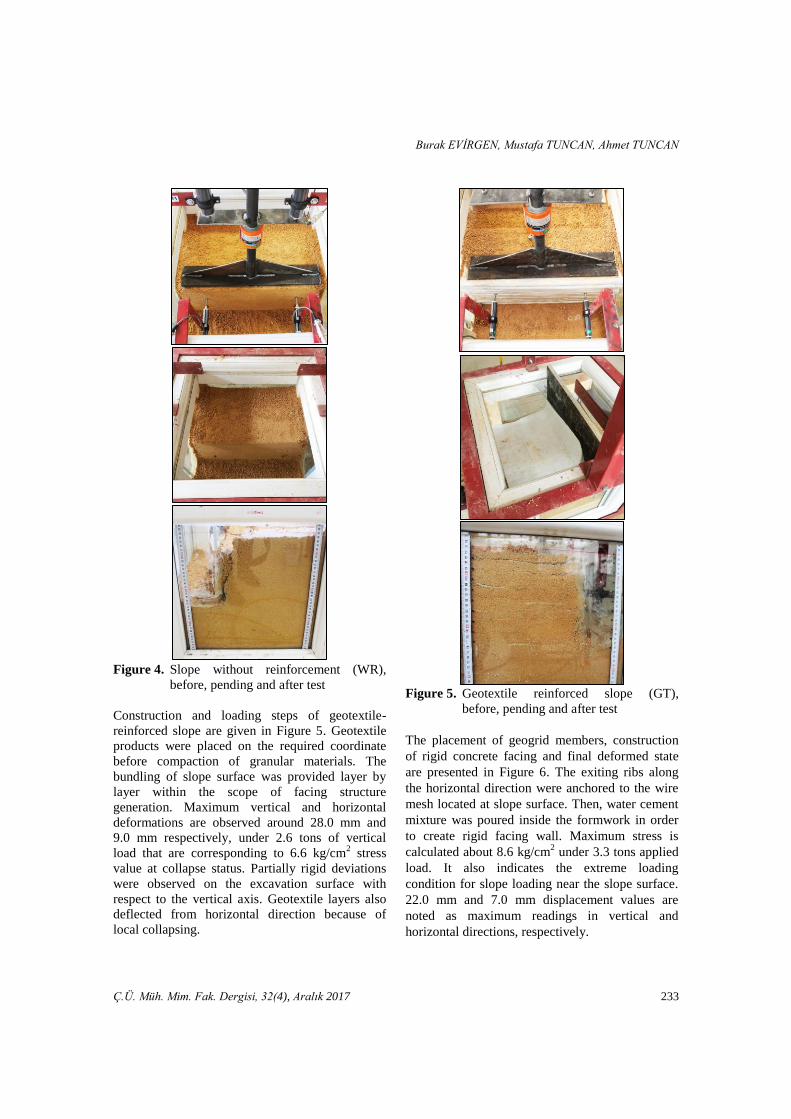
Figure 4. Slope without reinforcement (WR),
before, pending and after test
Construction and loading steps of geotextile-
reinforced slope are given in Figure 5. Geotextile
products were placed on the required coordinate
before compaction of granular materials. The
bundling of slope surface was provided layer by
layer within the scope of facing structure
generation. Maximum vertical and horizontal
deformations are observed around 28.0 mm and
9.0 mm respectively, under 2.6 tons of vertical
load that are corresponding to 6.6 kg/cm2 stress
value at collapse status. Partially rigid deviations
were observed on the excavation surface with
respect to the vertical axis. Geotextile layers also
deflected from horizontal direction because of
local collapsing.
Figure 5. Geotextile reinforced slope (GT),
before, pending and after test
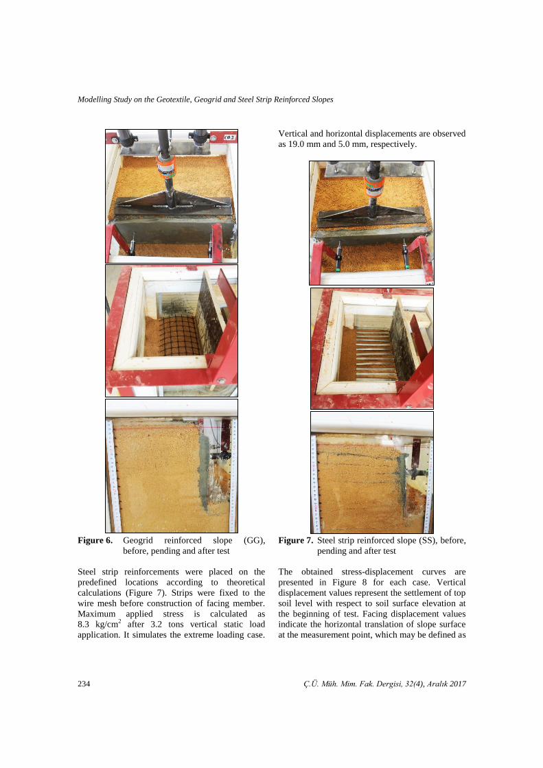
The placement of geogrid members, construction
of rigid concrete facing and final deformed state
are presented in Figure 6. The exiting ribs along
the horizontal direction were anchored to the wire
mesh located at slope surface. Then, water cement
mixture was poured inside the formwork in order
to create rigid facing wall. Maximum stress is
calculated about 8.6 kg/cm2 under 3.3 tons applied
load. It also indicates the extreme loading
condition for slope loading near the slope surface.
22.0 mm and 7.0 mm displacement values are
noted as maximum readings in vertical and
horizontal directions, respectively.
Modelling Study on the Geotextile, Geogrid and Steel Strip Reinforced Slopes
234 Ç.Ü. Müh. Mim. Fak. Dergisi, 32(4), Aralık 2017
Figure 6. Geogrid reinforced slope (GG),
before, pending and after test
Steel strip reinforcements were placed on the
predefined locations according to theoretical
calculations (Figure 7). Strips were fixed to the
wire mesh before construction of facing member.
Maximum applied stress is calculated as
8.3 kg/cm2 after 3.2 tons vertical static load
application. It simulates the extreme loading case.
Vertical and horizontal displacements are observed
as 19.0 mm and 5.0 mm, respectively.
Figure 7. Steel strip reinforced slope (SS), before,
pending and after test
The obtained stress-displacement curves are
presented in Figure 8 for each case. Vertical
displacement values represent the settlement of top
soil level with respect to soil surface elevation at
the beginning of test. Facing displacement values
indicate the horizontal translation of slope surface
at the measurement point, which may be defined as
Burak EVİRGEN, Mustafa TUNCAN, Ahmet TUNCAN
Ç.Ü. Müh. Mim. Fak. Dergisi, 32(4), Aralık 2017 235
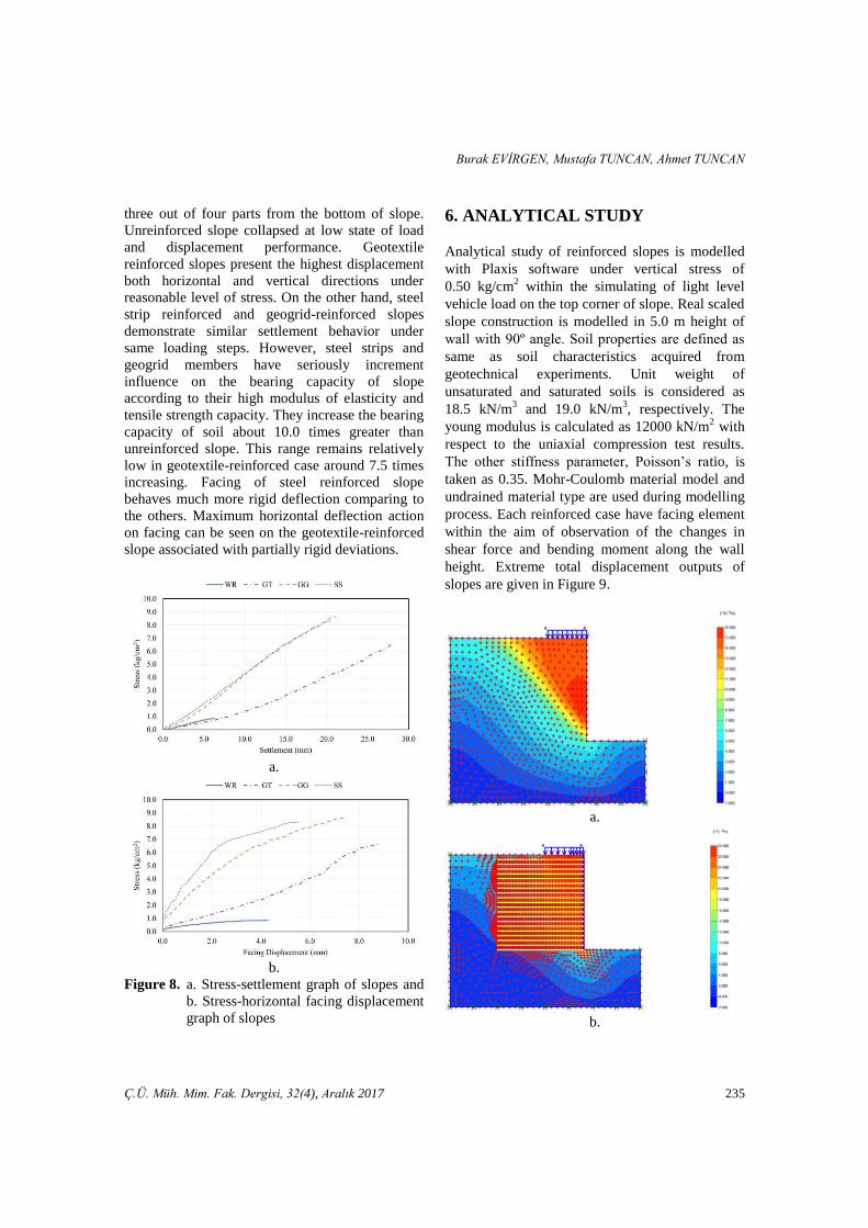
three out of four parts from the bottom of slope.
Unreinforced slope collapsed at low state of load
and displacement performance. Geotextile
reinforced slopes present the highest displacement
both horizontal and vertical directions under
reasonable level of stress. On the other hand, steel
strip reinforced and geogrid-reinforced slopes
demonstrate similar settlement behavior under
same loading steps. However, steel strips and
geogrid members have seriously increment
influence on the bearing capacity of slope
according to their high modulus of elasticity and
tensile strength capacity. They increase the bearing
capacity of soil about 10.0 times greater than
unreinforced slope. This range remains relatively
low in geotextile-reinforced case around 7.5 times
increasing. Facing of steel reinforced slope
behaves much more rigid deflection comparing to
the others. Maximum horizontal deflection action
on facing can be seen on the geotextile-reinforced
slope associated with partially rigid deviations.
a.
b.
Figure 8. a. Stress-settlement graph of slopes and
b. Stress-horizontal facing displacement
graph of slopes
6. ANALYTICAL STUDY
Analytical study of reinforced slopes is modelled
with Plaxis software under vertical stress of
0.50 kg/cm2 within the simulating of light level
vehicle load on the top corner of slope. Real scaled
slope construction is modelled in 5.0 m height of
wall with 90º angle. Soil properties are defined as
same as soil characteristics acquired from
geotechnical experiments. Unit weight of
unsaturated and saturated soils is considered as
18.5 kN/m3 and 19.0 kN/m
3, respectively. The
young modulus is calculated as 12000 kN/m2 with
respect to the uniaxial compression test results.
The other stiffness parameter, Poisson’s ratio, is
taken as 0.35. Mohr-Coulomb material model and
undrained material type are used during modelling
process. Each reinforced case have facing element
within the aim of observation of the changes in
shear force and bending moment along the wall
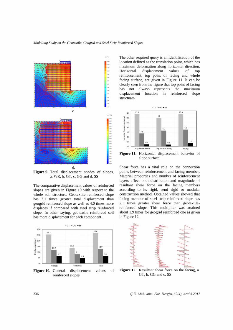
height. Extreme total displacement outputs of
slopes are given in Figure 9.
a.
b.
Modelling Study on the Geotextile, Geogrid and Steel Strip Reinforced Slopes
236 Ç.Ü. Müh. Mim. Fak. Dergisi, 32(4), Aralık 2017
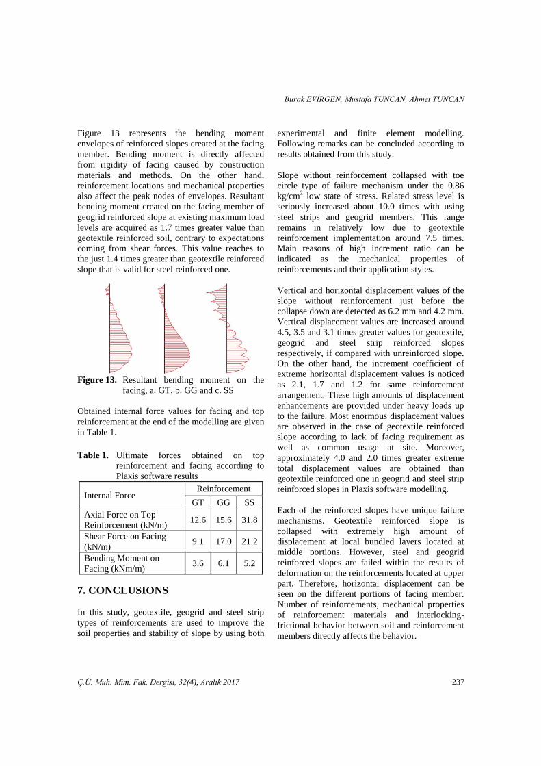
c.
d.
Figure 9. Total displacement shades of slopes,
a. WR, b. GT, c. GG and d. SS
The comparative displacement values of reinforced
slopes are given in Figure 10 with respect to the
whole soil structure. Geotextile reinforced slope
has 2.1 times greater total displacement than
geogrid reinforced slope as well as 4.0 times more
displaces if compared with steel strip reinforced
slope. In other saying, geotextile reinforced soil
has more displacement for each component.
Figure 10. General displacement values of
reinforced slopes
The other required query is an identification of the
location defined as the translation point, which has
maximum deformation along horizontal direction.
Horizontal displacement values of top
reinforcement, top point of facing and whole
facing surface, are given in Figure 11. It can be
clearly seen from the figure that top point of facing
has not always represents the maximum
displacement location in reinforced slope
structures.
Figure 11. Horizontal displacement behavior of
slope surface
Shear force has a vital role on the connection
points between reinforcement and facing member.
Material properties and number of reinforcement
layers affect both distribution and magnitude of
resultant shear force on the facing members
according to its rigid, semi rigid or modular
construction method. Obtained values showed that
facing member of steel strip reinforced slope has
2.3 times greater shear force than geotextile-
reinforced slope. This multiplier was attained
about 1.9 times for geogrid reinforced one as given
in Figure 12.
Figure 12. Resultant shear force on the facing, a.
GT, b. GG and c. SS
Burak EVİRGEN, Mustafa TUNCAN, Ahmet TUNCAN
Ç.Ü. Müh. Mim. Fak. Dergisi, 32(4), Aralık 2017 237
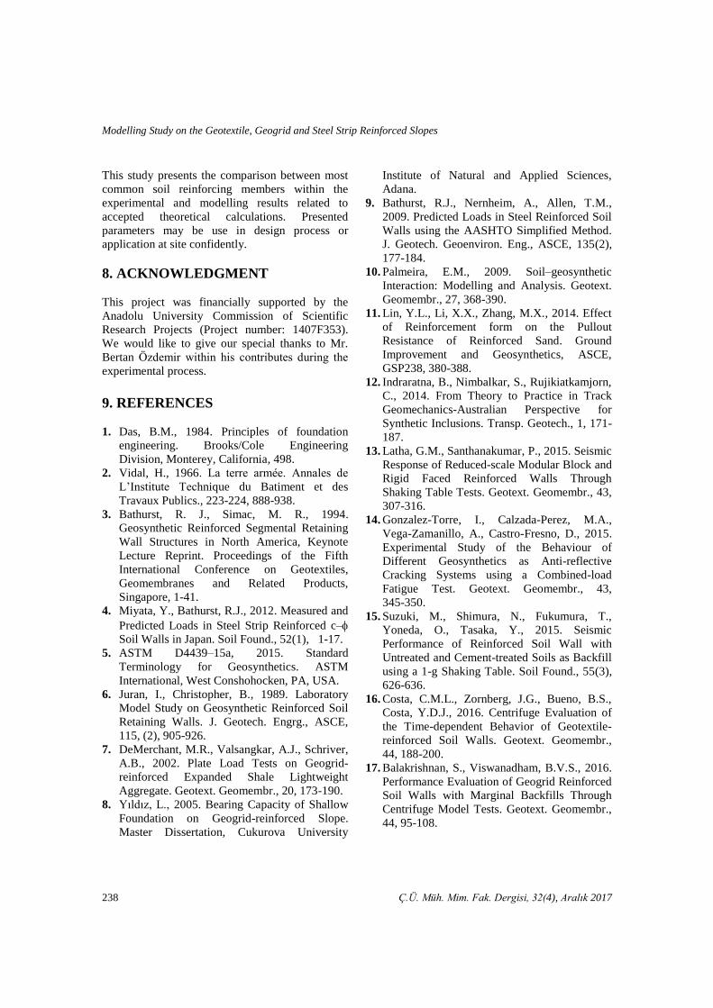
Figure 13 represents the bending moment
envelopes of reinforced slopes created at the facing
member. Bending moment is directly affected
from rigidity of facing caused by construction
materials and methods. On the other hand,
reinforcement locations and mechanical properties
also affect the peak nodes of envelopes. Resultant
bending moment created on the facing member of
geogrid reinforced slope at existing maximum load
levels are acquired as 1.7 times greater value than
geotextile reinforced soil, contrary to expectations
coming from shear forces. This value reaches to
the just 1.4 times greater than geotextile reinforced
slope that is valid for steel reinforced one.
Figure 13. Resultant bending moment on the
facing, a. GT, b. GG and c. SS
Obtained internal force values for facing and top
reinforcement at the end of the modelling are given
in Table 1.
Table 1. Ultimate forces obtained on top
reinforcement and facing according to
Plaxis software results
Internal Force Reinforcement
GT
GG SS
Axial Force on Top
Reinforcement (kN/m) 12.6 15.6 31.8
Shear Force on Facing
(kN/m) 9.1 17.0 21.2
Bending Moment on
Facing (kNm/m) 3.6 6.1 5.2
7. CONCLUSIONS
In this study, geotextile, geogrid and steel strip
types of reinforcements are used to improve the
soil properties and stability of slope by using both
experimental and finite element modelling.
Following remarks can be concluded according to
results obtained from this study.
Slope without reinforcement collapsed with toe
circle type of failure mechanism under the 0.86
kg/cm2 low state of stress. Related stress level is
seriously increased about 10.0 times with using
steel strips and geogrid members. This range
remains in relatively low due to geotextile
reinforcement implementation around 7.5 times.
Main reasons of high increment ratio can be
indicated as the mechanical properties of
reinforcements and their application styles.
Vertical and horizontal displacement values of the
slope without reinforcement just before the
collapse down are detected as 6.2 mm and 4.2 mm.
Vertical displacement values are increased around
4.5, 3.5 and 3.1 times greater values for geotextile,
geogrid and steel strip reinforced slopes
respectively, if compared with unreinforced slope.
On the other hand, the increment coefficient of
extreme horizontal displacement values is noticed
as 2.1, 1.7 and 1.2 for same reinforcement
arrangement. These high amounts of displacement
enhancements are provided under heavy loads up
to the failure. Most enormous displacement values
are observed in the case of geotextile reinforced
slope according to lack of facing requirement as
well as common usage at site. Moreover,
approximately 4.0 and 2.0 times greater extreme
total displacement values are obtained than
geotextile reinforced one in geogrid and steel strip
reinforced slopes in Plaxis software modelling.
Each of the reinforced slopes have unique failure
mechanisms. Geotextile reinforced slope is
collapsed with extremely high amount of
displacement at local bundled layers located at
middle portions. However, steel and geogrid
reinforced slopes are failed within the results of
deformation on the reinforcements located at upper
part. Therefore, horizontal displacement can be
seen on the different portions of facing member.
Number of reinforcements, mechanical properties
of reinforcement materials and interlocking-
frictional behavior between soil and reinforcement
members directly affects the behavior.
Modelling Study on the Geotextile, Geogrid and Steel Strip Reinforced Slopes
238 Ç.Ü. Müh. Mim. Fak. Dergisi, 32(4), Aralık 2017
This study presents the comparison between most
common soil reinforcing members within the
experimental and modelling results related to
accepted theoretical calculations. Presented
parameters may be use in design process or
application at site confidently.
8. ACKNOWLEDGMENT
This project was financially supported by the
Anadolu University Commission of Scientific
Research Projects (Project number: 1407F353).
We would like to give our special thanks to Mr.
Bertan Özdemir within his contributes during the
experimental process.
9. REFERENCES
1. Das, B.M., 1984. Principles of foundation
engineering. Brooks/Cole Engineering
Division, Monterey, California, 498.
2. Vidal, H., 1966. La terre armée. Annales de
L’Institute Technique du Batiment et des
Travaux Publics., 223-224, 888-938.
3. Bathurst, R. J., Simac, M. R., 1994.
Geosynthetic Reinforced Segmental Retaining
Wall Structures in North America, Keynote
Lecture Reprint. Proceedings of the Fifth
International Conference on Geotextiles,
Geomembranes and Related Products,
Singapore, 1-41.
4. Miyata, Y., Bathurst, R.J., 2012. Measured and
Predicted Loads in Steel Strip Reinforced c–
Soil Walls in Japan. Soil Found., 52(1), 1-17.
5. ASTM D4439–15a, 2015. Standard
Terminology for Geosynthetics. ASTM
International, West Conshohocken, PA, USA.
6. Juran, I., Christopher, B., 1989. Laboratory
Model Study on Geosynthetic Reinforced Soil
Retaining Walls. J. Geotech. Engrg., ASCE,
115, (2), 905-926.
7. DeMerchant, M.R., Valsangkar, A.J., Schriver,
A.B., 2002. Plate Load Tests on Geogrid-
reinforced Expanded Shale Lightweight
Aggregate. Geotext. Geomembr., 20, 173-190.
8. Yıldız, L., 2005. Bearing Capacity of Shallow
Foundation on Geogrid-reinforced Slope.
Master Dissertation, Cukurova University
Institute of Natural and Applied Sciences,
Adana.
9. Bathurst, R.J., Nernheim, A., Allen, T.M.,
2009. Predicted Loads in Steel Reinforced Soil
Walls using the AASHTO Simplified Method.
J. Geotech. Geoenviron. Eng., ASCE, 135(2),
177-184.
10. Palmeira, E.M., 2009. Soil–geosynthetic
Interaction: Modelling and Analysis. Geotext.
Geomembr., 27, 368-390.
11. Lin, Y.L., Li, X.X., Zhang, M.X., 2014. Effect
of Reinforcement form on the Pullout
Resistance of Reinforced Sand. Ground
Improvement and Geosynthetics, ASCE,
GSP238, 380-388.
12. Indraratna, B., Nimbalkar, S., Rujikiatkamjorn,
C., 2014. From Theory to Practice in Track
Geomechanics-Australian Perspective for
Synthetic Inclusions. Transp. Geotech., 1, 171-
187.
13. Latha, G.M., Santhanakumar, P., 2015. Seismic
Response of Reduced-scale Modular Block and
Rigid Faced Reinforced Walls Through
Shaking Table Tests. Geotext. Geomembr., 43,
307-316.
14. Gonzalez-Torre, I., Calzada-Perez, M.A.,
Vega-Zamanillo, A., Castro-Fresno, D., 2015.
Experimental Study of the Behaviour of
Different Geosynthetics as Anti-reflective
Cracking Systems using a Combined-load
Fatigue Test. Geotext. Geomembr., 43,
345-350.
15. Suzuki, M., Shimura, N., Fukumura, T.,
Yoneda, O., Tasaka, Y., 2015. Seismic
Performance of Reinforced Soil Wall with
Untreated and Cement-treated Soils as Backfill
using a 1-g Shaking Table. Soil Found., 55(3),
626-636.
16. Costa, C.M.L., Zornberg, J.G., Bueno, B.S.,
Costa, Y.D.J., 2016. Centrifuge Evaluation of
the Time-dependent Behavior of Geotextile-
reinforced Soil Walls. Geotext. Geomembr.,
44, 188-200.
17. Balakrishnan, S., Viswanadham, B.V.S., 2016.
Performance Evaluation of Geogrid Reinforced
Soil Walls with Marginal Backfills Through
Centrifuge Model Tests. Geotext. Geomembr.,
44, 95-108.
Burak EVİRGEN, Mustafa TUNCAN, Ahmet TUNCAN
Ç.Ü. Müh. Mim. Fak. Dergisi, 32(4), Aralık 2017 239
18. Xiao, C., Han, J., Zhang, Z., 2016.
Experimental Study on Performance of
Geosynthetic-reinforced Soil Model Walls on
Rigid Foundations Subjected to Static Footing
Loading. Geotext. Geomembr. 44, 81-94.
19. Lal, D., Sankar, N., Chandrakaran, S., 2017.
Effect of Reinforcement Form on the
Behaviour of Coir Geotextile Reinforced Sand
Beds. Soil Found., 57(2), 227-236.
20. Al-Rkaby, A.H.J., Chegenizadeh, A., Nikraz,
H.R., 2017. Anisotropic Strength of Large
Scale Geogrid-reinforced Sand: Experimental
Study. Soil Found., 57(4), 557-574.
21. Richardson, G.N., 1995. Lessons Learned from
the Failure of a Geotextile Reinforced
Retaining Wall Facing.
http://www.smithgardnerinc.com/docs/.
22. Kim, Y-S., Won, M-S., 2006. Deformation
Behaviors of Geosynthetic Reinforced Soil
Walls on Shallow Weak Ground. Soil Stress-
Strain Behavior: Measurement, Modeling and
Analysis Geotechnical Symposium in Roma,
Italy, 819-830.
23. Stuedlein, A.W., Bailey, M., Lindquist, D.
Sankey, J., Neely, W.J., 2010. Design and
Performance of a 46-m-high MSE Wall. J.
Geotech. Geoenviron. Eng., ASCE, 136(6),
786-796.
24. Yonezawa, T., Yamazaki, T., Tateyama, M.,
Tatsuoka, F., 2014. Design and Construction of
Geosynthetic-reinforced Soil Structures for
Hokkaido High-speed Train Line. Transp.
Geotech., 1, 3-20.
25. Liu, S., Lu, Y., Weng, L., Bai, F., 2015. Field
Study of Treatment for Expansive Soil/rock
Channel Slope with Soilbags. Geotext.
Geomembr., 43, 283-292.
26. Jones, J.C.F.P., 1988. Earth Reinforcement and
Soil Structures, Revised Reprint. Butterworth
Advance Series in Geotechnical Engineering,
Anchor Brendon Ltd, Tiptree, Essex.
27. Yılmaz, H.R., Aklık, P., 2002. Geotekstil veya
Geogrid Kullanılarak Oluşturulan Dayanma
Yapılarında Sağlanabilen Ekonomi Hakkında
Bir İnceleme. 9th
National Conference of Soil
Mechanics and Foundation Engineering,
Eskisehir, 312-321.
28. Allen, T.M., Bathurst, R.J., Holtz, R.D., Lee,
W.F., Walters, D., 2004. New Method for
Prediction of Loads in Steel Reinforced Soil
Walls. J. Geotech. Geoenviron. Eng., ASCE,
130(11), 1109-1120.
29. Hatami, K., Bathurst, R.J., 2006. Numerical
Model for Reinforced Soil Segmental Walls
Under Surcharge Loading. J. Geotech.
Geoenviron. Eng., ASCE, 132(6), 673-684.
30. Lin, Y.L., Li, X.X., Zhang, M.X., 2010. Limit
Analysis of Reinforced Soil Slopes Based on
Composite Reinforcement Mechanism. Ground
Improvement and Geosynthetics, ASCE,
GSP207, 59-64.
31. Gu, J., 2011. Computational Modeling of
Geogrid Reinforced Soil Foundation and
Geogrid Reinforced Base in Flexible
Pavement. Ph.D. Dissertation, Graduate
Faculty of the Louisiana State University.
32. Damians, I.P., Bathurst, R.J., Josa, A., Lloret,
A., Albuquerque, P.J.R., 2013. Vertical-facing
Loads in Steel-reinforced Soil Walls. J.
Geotech. Geoenviron. Eng., ASCE, 139(9),
1419-1432.
33. Yu, X., Pradhan, A., 2014. Study of Geogrid
Reinforcement using Two Dimensional
Discrete Element Method. Ground
Improvement and Geosynthetics, ASCE,
GSP238, 299-311.
34. Hou, J., Zhang, M.X., Zhang, T.T., 2014.
Comparison of Strip-reinforced with H-V
Reinforced Foundation using FEM. Ground
Improvement and Geosynthetics, ASCE,
GSP238, 404-413.
35. Yu, Y., Bathurst, R.J., Miyata, Y., 2015.
Numerical Analysis of a Mechanically
Stabilized Earth Wall Reinforced with Steel
Strips. Soil Found., 55(3), 536-547.
36. Carbone, L., Gourc, J.B., Carrubba, P.,
Pavanello, P., Moraci, N., 2015. Dry Friction
Behaviour of a Geosynthetic Interface using
Inclined Plane and Shaking Table Tests.
Geotext. Geomembr., 43, 293-306.
37. Allen, T.M., Bathurst, R.J., 2015. Improved
Simplified Method for Prediction of Loads in
Reinforced Soil Walls. J. Geotech. Geoenviron.
Eng., ASCE, 141(11), 04015049-1-14.
38. Liu, H., 2015. Reinforcement Load and
Compression of Reinforced Soil Mass under
Surcharge Loading. J. Geotech. Geoenviron.
Eng., ASCE, 141(6), 04015017-1-10.

Modelling Study on the Geotextile, Geogrid and Steel Strip Reinforced Slopes
240 Ç.Ü. Müh. Mim. Fak. Dergisi, 32(4), Aralık 2017
39. Damians, I.P., Bathurst, R.J., Josa, A., Lloret,
A., 2015. Numerical Analysis of an
Instrumented Steel-reinforced Soil Wall. Int. J.
Geomech., ASCE, 15(1), 04014037-1-15.
40. Gao, Y., Yang, S., Zhang, F., Leshchinsky, B.,
2016. Three-dimensional Reinforced Slopes:
Evaluation of Required Reinforcement
Strength and Embedment Length using Limit
Analysis. Geotext. Geomembr., 44, 133-142.
41. ASTM D6637/D6637M–15, 2015. Standard
Test Method for Determining Tensile
Properties of Geogrids by the Single or Multi-
rib Tensile Method. ASTM International, West
Conshohocken, PA, USA.
42. ASTM D4533/D4533M–15, 2015. Standard
test Method for Trapezoid Tearing Strength of
Geotextiles. ASTM International, West
Conshohocken, PA, USA.
43. ASTM E8/E8M–15a, 2015. Standard test
Methods for Tension Testing of Metallic
Materials. ASTM International, West
Conshohocken, PA, USA.
44. FHWA-RD-89-04, 1990. Reinforced Soil
Structures Volume I. Design and Construction
Guidelines. U.S. Department of Transportation
Federal Highway Administration, Virginia,
United States.
45. FHWA-HRT-14-094, 2015. Synthesis of
Geosynthetic Reinforced Soil (GRS) Design
Topics. U.S. Department of Transportation
Federal Highway Administration, Virginia,
United States.
46. Sun, C., Graves, C., 2013. Mechanically
Stabilized Earth (MSE) Walls Design
Guidance. University of Kentucky
Transportation Center.
47. Miyata, Y., Bathurst, R.J., 2012. Reliability
Analysis of Soil-geogrid Pullout Models in
Japan. Soil Found., 52(4), 620-633.
48. Wu, Y., Prakash, S., 1999. Effect of
Submergence on Seismic Displacement of
Rigid Walls. Second International Conference
on Earthquake Geotechnical and Soil
Dynamics, Lisbon, 277-289.
49. JRA, 1996. Seismic Design Specifications and
Construction of Highway Bridges. Japan Road
Association.
50. NGG, 2005. Nordic Guidelines for Reinforced
Soils and Fills. Nordic Geosynthetic Group,
www.sgf.net.
51. PWRC, 2000. Design and Construction Manual
of Geosynthetics Reinforced Soil, Revised
Version. Public Works Research Center,
Tsukuba, Japan.
52. NCMA, 2009. Design Manual for Segmental
Retaining Walls, 3rd
ed. National Concrete
Masonry Association, Herndon, VA, USA.
53. Özdemir, B., Evirgen, B., Tuncan, A., Onur,
M.İ., Tuncan, M. 2015. Zemin Donatıları ile
Güçlendirilmiş Şevlerin Değerlendirilmesi. 6.
Geotechnical Symposium, Adana, 105.
54. Onur, M.İ, Tuncan, M., Evirgen, B., Ozdemir,
B., Tuncan, A., 2016. Behavior of Soil
Reinforcements in Slopes. Procedia
Engineering., 143, 483-489.