Embed Size (px)
Citation preview

Cruising the Strip: Terminal Strip Editor in
AutoCAD® Electrical Jared Bunch – Autodesk, Inc.
MA4622
There are so many destinations along the strip to choose from that sometimes it can become overwhelming. If you have ever felt this way, then you should ride along with us for our guided cruise down the Terminal Strip Editor. This ride will make frequent stops at destinations such as jumpers, spares and accessories, and editing. Oh, and let’s not forget to stop at some of the most popular destinations along the strip, such as Graphical and Tabular Terminal Strips and Jumper Charts.
Learning Objectives At the end of this class, you will be able to:
Perform general terminal edits/modifications with terminal strip editor
Add/edit spare terminals and accessories
Assign/modify terminal jumpers
Insert graphical terminal strips, tabular terminal strips, and jumper charts
Begin working with multi-level terminals
About the Speaker
Jared Bunch, a Senior User Experience Designer has been with Autodesk for over eight years. In
addition to his current role, during his time at Autodesk Jared has also been an important member of the
Product Support and Sales teams as a Support Specialist and a Solutions Engineer. Jared has over 10
years of experience with the AutoCAD® Electrical product, and during this time has traveled the world
conducting training classes, user testing events, customer meetings, etc. both helping AutoCAD®
Electrical be successful and helping users and resellers be successful with AutoCAD® Electrical.
Email: [email protected]
Cruising the Strip: Terminal Strip Editor in AutoCAD® Electrical
2
Accessing the Terminal Strip Editor Command Terminal Strip Editor is a powerful feature within AutoCAD Electrical. It provides you a single
interface to perform many different actions on terminals that are part of the same terminal strip. Without
the Terminal Strip Editor tool you would have to go and edit each terminal individually which is very time
consuming and error prone.
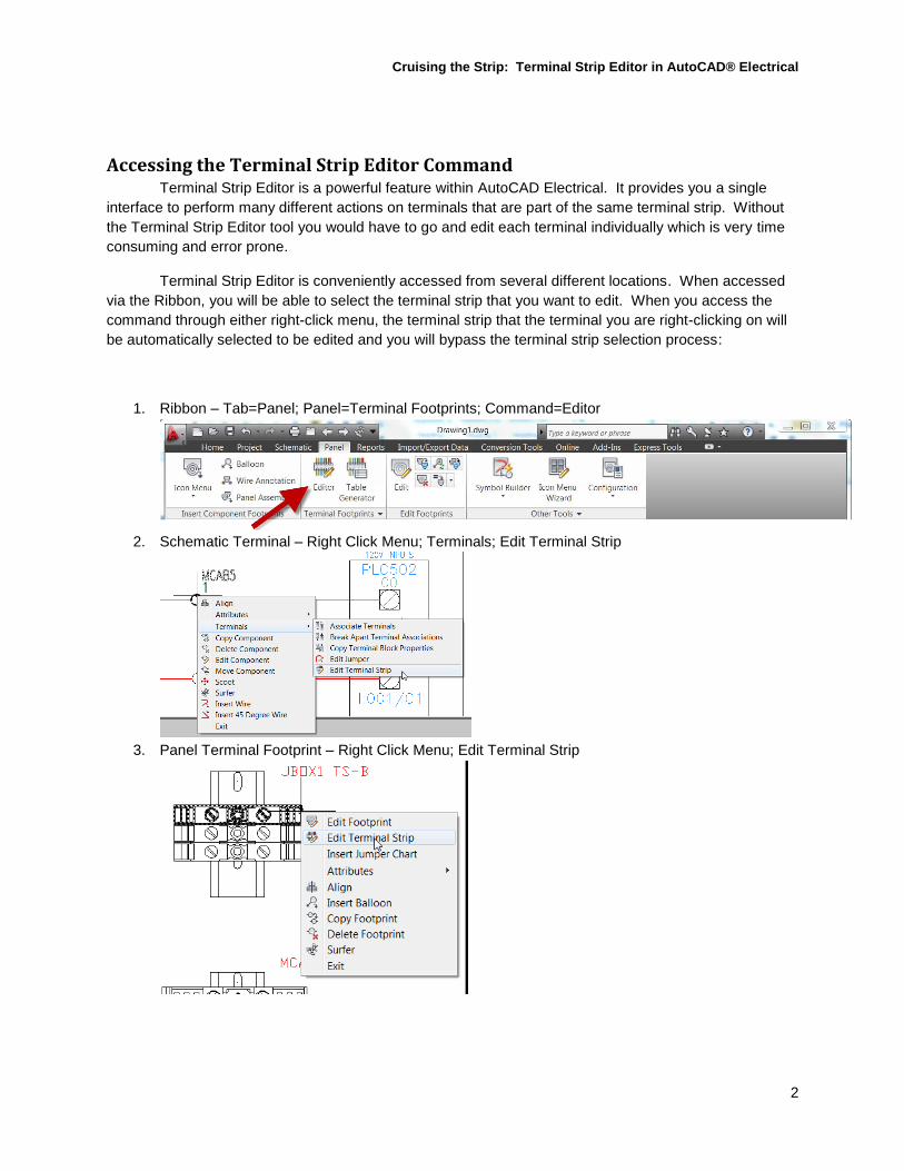
Terminal Strip Editor is conveniently accessed from several different locations. When accessed
via the Ribbon, you will be able to select the terminal strip that you want to edit. When you access the
command through either right-click menu, the terminal strip that the terminal you are right-clicking on will
be automatically selected to be edited and you will bypass the terminal strip selection process:
1. Ribbon – Tab=Panel; Panel=Terminal Footprints; Command=Editor
2. Schematic Terminal – Right Click Menu; Terminals; Edit Terminal Strip
3. Panel Terminal Footprint – Right Click Menu; Edit Terminal Strip
Cruising the Strip: Terminal Strip Editor in AutoCAD® Electrical
3
Understanding Terminal Strip Editor This section will help you to get familiar with the Terminal Strip Editor environment and the many
things that you can accomplish with the tool, several of which we will be covering during the class.
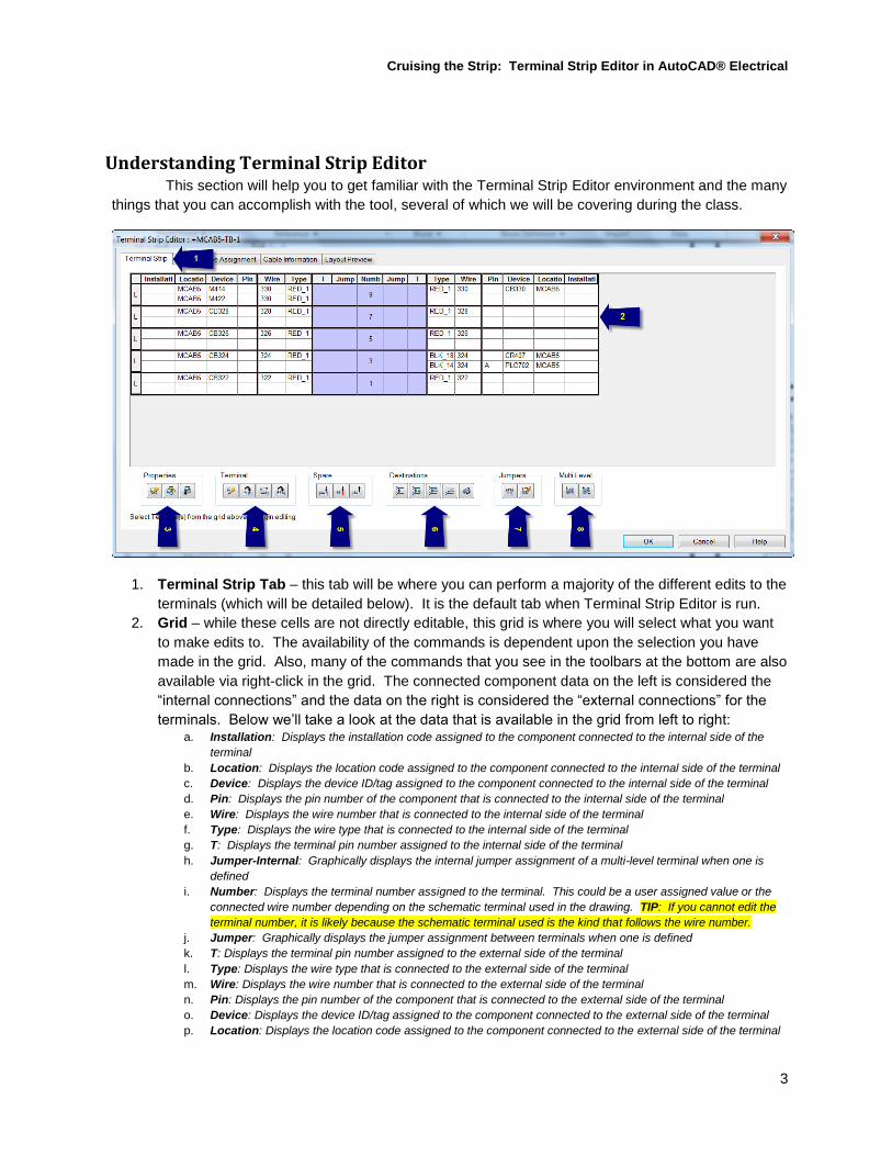
1. Terminal Strip Tab – this tab will be where you can perform a majority of the different edits to the
terminals (which will be detailed below). It is the default tab when Terminal Strip Editor is run.
2. Grid – while these cells are not directly editable, this grid is where you will select what you want
to make edits to. The availability of the commands is dependent upon the selection you have
made in the grid. Also, many of the commands that you see in the toolbars at the bottom are also
available via right-click in the grid. The connected component data on the left is considered the
“internal connections” and the data on the right is considered the “external connections” for the
terminals. Below we’ll take a look at the data that is available in the grid from left to right: a. Installation: Displays the installation code assigned to the component connected to the internal side of the
terminal
b. Location: Displays the location code assigned to the component connected to the internal side of the terminal
c. Device: Displays the device ID/tag assigned to the component connected to the internal side of the terminal
d. Pin: Displays the pin number of the component that is connected to the internal side of the terminal
e. Wire: Displays the wire number that is connected to the internal side of the terminal
f. Type: Displays the wire type that is connected to the internal side of the terminal
g. T: Displays the terminal pin number assigned to the internal side of the terminal
h. Jumper-Internal: Graphically displays the internal jumper assignment of a multi-level terminal when one is
defined
i. Number: Displays the terminal number assigned to the terminal. This could be a user assigned value or the
connected wire number depending on the schematic terminal used in the drawing. TIP: If you cannot edit the
terminal number, it is likely because the schematic terminal used is the kind that follows the wire number.
j. Jumper: Graphically displays the jumper assignment between terminals when one is defined
k. T: Displays the terminal pin number assigned to the external side of the terminal
l. Type: Displays the wire type that is connected to the external side of the terminal
m. Wire: Displays the wire number that is connected to the external side of the terminal
n. Pin: Displays the pin number of the component that is connected to the external side of the terminal
o. Device: Displays the device ID/tag assigned to the component connected to the external side of the terminal
p. Location: Displays the location code assigned to the component connected to the external side of the terminal
Cruising the Strip: Terminal Strip Editor in AutoCAD® Electrical
4
q. Installation: Displays the installation code assigned to the component connected to the external side of the
terminal
3. Properties Command Group – group of commands which allows you to work
with/manipulate/assign terminal block properties such as: numbers of levels, level description,
number of wires per connection allowed, pin ID’s and internal jumper assignments a. Edit Terminal Block Properties: allows you to edit the properties assigned to the selected terminal block(see
the list of properties above) TIP: Most of these properties would be assigned through the catalog database
then inherited by the terminal block instance when a catalog number is selected. The changes you make here
are treated as overrides.
b. Copy Terminal Block Properties: allows you to copy the properties (those detailed above) from a selected
terminal
c. Paste Terminal Block Properties: allows you to paste the previously copied terminal block properties to the
terminal(s) now selected
4. Terminal Command Group – group of commands which allows you to perform common edits on
terminals, spare terminals, and accessories a. Edit Terminal: allows you to edit the installation code, location code, terminal strip and terminal number
assignment for the selected terminal
b. Reassign Terminal: allows you to reassign the selected terminal(s) to another terminal strip. The result will be
the selected terminal(s) removal from the current terminal strip being edited and added to the terminal strip
selected to reassign them to. NOTE: Accessories cannot be reassigned, only terminals (including spare
terminals) can be reassigned
c. Renumber Terminal: allows you to quickly renumber the selected terminal(s). TIP: You can quickly select all
of the terminal strip items in the grid by right-clicking and choosing “Select All”
d. Move Terminal: allows you to move the selected terminal(s) up or down. It also provides you the options for
“Pick Above” or “Pick Below” which can facilitate a much quicker move than using the up or down options.
5. Spare Command Group – group of commands which allows you to insert and delete spare
terminals or accessories a. Insert Spare Terminal: allows you to insert one or more spare terminals with a terminal number assignment
and catalog details
b. Insert Accessory: allows you to insert one or more terminal accessory with a number/ID assignment and
catalog details
c. Delete Spare Terminals/Accessories: allows you to delete spare terminals or accessories that may be no
longer needed in the terminal strip due to design changes, etc.
6. Destinations Command Group – group of commands which allows you to manipulate the
connection to the external/internal sides of the terminal a. Toggle Location: allows you to quickly toggle all components assigned to a particular location between the
internal and external sides of the terminals
b. Toggle Installation: allows you to quickly toggle all components assigned to a particular installation between
the internal and external sides of the terminals
c. Toggle Terminal Destinations: allows you to toggle the connected components of the selected terminal from
the internal to external or external to internal side of that terminal
d. Switch Terminal Destinations: allows you to quickly switch the internal and external connections of a terminal
resulting in the connections that were on the internal side to then be on the external side and those that were on
the external side to then be on the internal side.
e. Move Destination: allows you to move the connected component up or down within the terminal. When
“extra” terminals have been added due to wiring constraints being exceeded, destination can be moved
between this “extra” terminal and the original terminal as needed.
7. Jumpers Command Group – group of commands which allow you to assign and modify jumper
definitions for the terminal strip a. Assign Jumper: allows you to define a jumper between multiple terminals that are selected. You can assign
catalog information for the jumper here as well. TIP: When jumpers are introduced, the wire numbers will
commonly need to be updated if they have already been assigned. With the use of a Task dialog, AutoCAD
Electrical recognizes this and will facilitate the action of running the automatic wire number command.
b. Edit/Delete Jumper: allows you to edit a jumper be adding/removing terminals and to edit the catalog
assignment. Alternately, you could delete the jumper definition all together.
Cruising the Strip: Terminal Strip Editor in AutoCAD® Electrical
5
8. Multi-Level Command Group – group of commands which allow you to define and manipulate
multi-level terminal definitions a. Associate Terminals: allows you to merge separate terminals into a single, multi-level terminal. NOTE: At
least one terminal must be defined as a multi-level terminal through the terminal property assignments.
b. Break Apart Terminal Associations: allows you to quickly break apart an existing multi-level terminal
definition. You could take multiple levels and break them into a separate, new multi-level terminal or you could
have them broken out into separate, new single level terminal definitions.
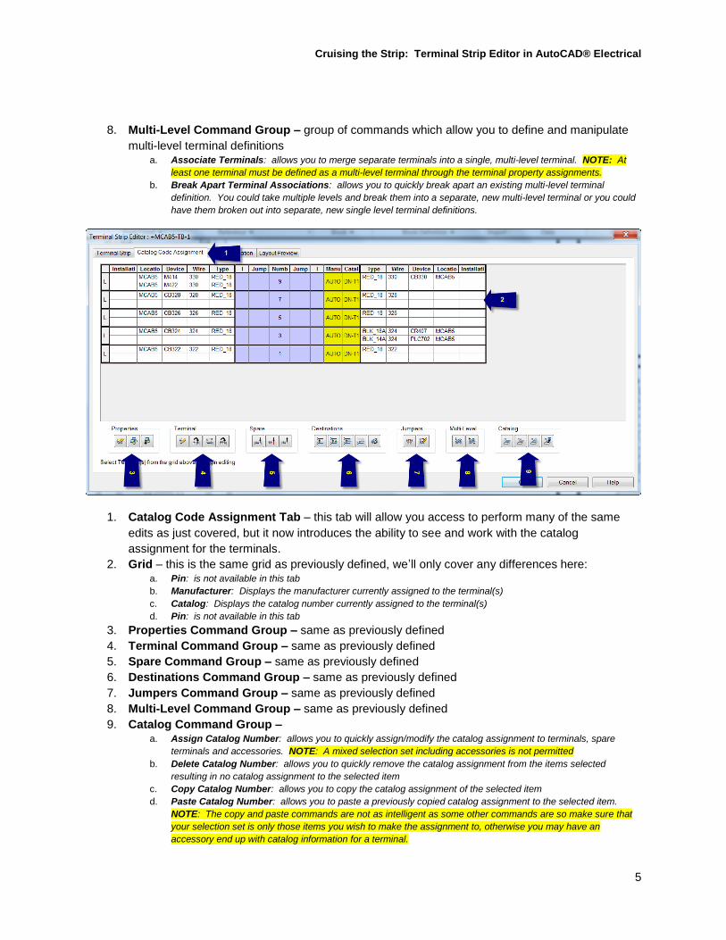
1. Catalog Code Assignment Tab – this tab will allow you access to perform many of the same
edits as just covered, but it now introduces the ability to see and work with the catalog
assignment for the terminals.
2. Grid – this is the same grid as previously defined, we’ll only cover any differences here: a. Pin: is not available in this tab
b. Manufacturer: Displays the manufacturer currently assigned to the terminal(s)
c. Catalog: Displays the catalog number currently assigned to the terminal(s)
d. Pin: is not available in this tab
3. Properties Command Group – same as previously defined
4. Terminal Command Group – same as previously defined
5. Spare Command Group – same as previously defined
6. Destinations Command Group – same as previously defined
7. Jumpers Command Group – same as previously defined
8. Multi-Level Command Group – same as previously defined
9. Catalog Command Group – a. Assign Catalog Number: allows you to quickly assign/modify the catalog assignment to terminals, spare
terminals and accessories. NOTE: A mixed selection set including accessories is not permitted
b. Delete Catalog Number: allows you to quickly remove the catalog assignment from the items selected
resulting in no catalog assignment to the selected item
c. Copy Catalog Number: allows you to copy the catalog assignment of the selected item
d. Paste Catalog Number: allows you to paste a previously copied catalog assignment to the selected item.
NOTE: The copy and paste commands are not as intelligent as some other commands are so make sure that
your selection set is only those items you wish to make the assignment to, otherwise you may have an
accessory end up with catalog information for a terminal.
Cruising the Strip: Terminal Strip Editor in AutoCAD® Electrical
6
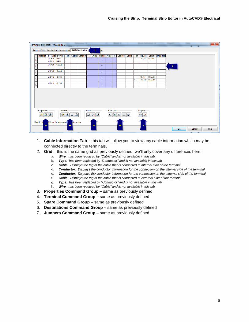
1. Cable Information Tab – this tab will allow you to view any cable information which may be
connected directly to the terminals.
2. Grid – this is the same grid as previously defined, we’ll only cover any differences here: a. Wire: has been replaced by “Cable” and is not available in this tab
b. Type: has been replaced by “Conductor” and is not available in this tab
c. Cable: Displays the tag of the cable that is connected to internal side of the terminal
d. Conductor: Displays the conductor information for the connection on the internal side of the terminal
e. Conductor: Displays the conductor information for the connection on the external side of the terminal
f. Cable: Displays the tag of the cable that is connected to external side of the terminal
g. Type: has been replaced by “Conductor” and is not available in this tab
h. Wire: has been replaced by “Cable” and is not available in this tab
3. Properties Command Group – same as previously defined
4. Terminal Command Group – same as previously defined
5. Spare Command Group – same as previously defined
6. Destinations Command Group – same as previously defined
7. Jumpers Command Group – same as previously defined
Cruising the Strip: Terminal Strip Editor in AutoCAD® Electrical
7
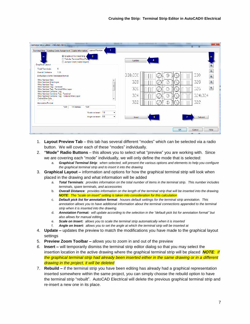
1. Layout Preview Tab – this tab has several different “modes” which can be selected via a radio
button. We will cover each of these “modes” individually.
2. “Mode” Radio Buttons – this allows you to select what “preview” you are working with. Since
we are covering each “mode” individually, we will only define the mode that is selected: a. Graphical Terminal Strip: when selected, will present the various options and elements to help you configure
the graphical terminal strip and to insert it into the drawing
3. Graphical Layout – information and options for how the graphical terminal strip will look when
placed in the drawing and what information will be added a. Total Terminals: provides information on the total number of items in the terminal strip. This number includes
terminals, spare terminals, and accessories
b. Overall Distance: provides information on the length of the terminal strip that will be inserted into the drawing.
NOTE: The “scale on insert” setting is taken into consideration for this calculation
c. Default pick list for annotation format: houses default settings for the terminal strip annotation. This
annotation allows you to have additional information about the terminal connections appended to the terminal
strip when it is inserted into the drawing.
d. Annotation Format: will update according to the selection in the “default pick list for annotation format” but
also allows for manual editing
e. Scale on Insert: allows you to scale the terminal strip automatically when it is inserted
f. Angle on Insert: allows you to set the angle at which the terminal strip will be inserted at
4. Update – updates the preview to match the modifications you have made to the graphical layout
settings
5. Preview Zoom Toolbar – allows you to zoom in and out of the preview
6. Insert – will temporarily dismiss the terminal strip editor dialog so that you may select the
insertion location in the active drawing where the graphical terminal strip will be placed NOTE: If
the graphical terminal strip had already been inserted either in the same drawing or in a different
drawing in the project, it will be deleted
7. Rebuild – if the terminal strip you have been editing has already had a graphical representation
inserted somewhere within the same project, you can simply choose the rebuild option to have
the terminal strip “rebuilt”. AutoCAD Electrical will delete the previous graphical terminal strip and
re-insert a new one in its place.
Cruising the Strip: Terminal Strip Editor in AutoCAD® Electrical
8
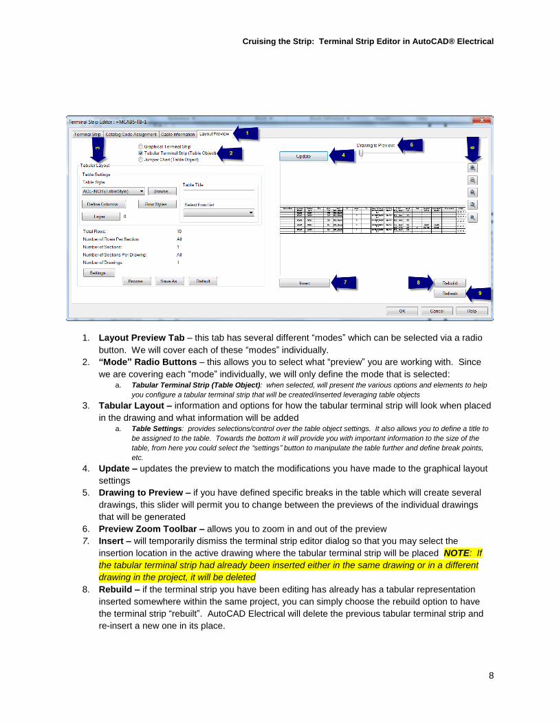
1. Layout Preview Tab – this tab has several different “modes” which can be selected via a radio
button. We will cover each of these “modes” individually.
2. “Mode” Radio Buttons – this allows you to select what “preview” you are working with. Since
we are covering each “mode” individually, we will only define the mode that is selected: a. Tabular Terminal Strip (Table Object): when selected, will present the various options and elements to help
you configure a tabular terminal strip that will be created/inserted leveraging table objects
3. Tabular Layout – information and options for how the tabular terminal strip will look when placed
in the drawing and what information will be added a. Table Settings: provides selections/control over the table object settings. It also allows you to define a title to
be assigned to the table. Towards the bottom it will provide you with important information to the size of the
table, from here you could select the “settings” button to manipulate the table further and define break points,
etc.
4. Update – updates the preview to match the modifications you have made to the graphical layout
settings
5. Drawing to Preview – if you have defined specific breaks in the table which will create several
drawings, this slider will permit you to change between the previews of the individual drawings
that will be generated
6. Preview Zoom Toolbar – allows you to zoom in and out of the preview
7. Insert – will temporarily dismiss the terminal strip editor dialog so that you may select the
insertion location in the active drawing where the tabular terminal strip will be placed NOTE: If
the tabular terminal strip had already been inserted either in the same drawing or in a different
drawing in the project, it will be deleted
8. Rebuild – if the terminal strip you have been editing has already has a tabular representation
inserted somewhere within the same project, you can simply choose the rebuild option to have
the terminal strip “rebuilt”. AutoCAD Electrical will delete the previous tabular terminal strip and
re-insert a new one in its place.
Cruising the Strip: Terminal Strip Editor in AutoCAD® Electrical
9
9. Refresh – if the changes that have been made to the tabular terminal strip only involve the data,
and you do not want any of the table formatting to change, you can select “refresh” which will only
refresh the data in the existing table
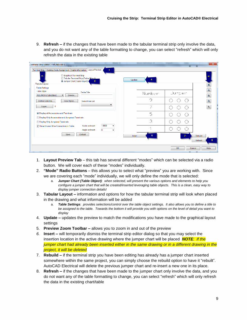
1. Layout Preview Tab – this tab has several different “modes” which can be selected via a radio
button. We will cover each of these “modes” individually.
2. “Mode” Radio Buttons – this allows you to select what “preview” you are working with. Since
we are covering each “mode” individually, we will only define the mode that is selected: a. Jumper Chart (Table Object): when selected, will present the various options and elements to help you
configure a jumper chart that will be created/inserted leveraging table objects. This is a clean, easy way to
display jumper connection details!
3. Tabular Layout – information and options for how the tabular terminal strip will look when placed
in the drawing and what information will be added a. Table Settings: provides selections/control over the table object settings. It also allows you to define a title to
be assigned to the table. Towards the bottom it will provide you with options on the level of detail you want to
display
4. Update – updates the preview to match the modifications you have made to the graphical layout
settings
5. Preview Zoom Toolbar – allows you to zoom in and out of the preview
6. Insert – will temporarily dismiss the terminal strip editor dialog so that you may select the
insertion location in the active drawing where the jumper chart will be placed NOTE: If the
jumper chart had already been inserted either in the same drawing or in a different drawing in the
project, it will be deleted
7. Rebuild – if the terminal strip you have been editing has already has a jumper chart inserted
somewhere within the same project, you can simply choose the rebuild option to have it “rebuilt”.
AutoCAD Electrical will delete the previous jumper chart and re-insert a new one in its place.
8. Refresh – if the changes that have been made to the jumper chart only involve the data, and you
do not want any of the table formatting to change, you can select “refresh” which will only refresh
the data in the existing chart/table