Embed Size (px)
Citation preview
UNCLASSIFIED
Modelling Australian Red Brick and Bluestone Walls in VAPO
Matthew Lukaszewicz and Christine Pienaar
Weapons Systems Division Defence Science and Technology Organisation
DSTO-TN-1155
ABSTRACT To confidently predict structural and building damage due to explosive blast loads, Threat Mitigation Group, Weapons Systems Division, is comparing, improving and validating existing modelling tools. For conventional structures, the Vulnerability Assessment and Protection Options (VAPO) software, a product of the Defense Threat Reduction Agency (DTRA), is DSTO's primary effects prediction software tool due to the rapidity with which an analysis can be conducted and the ability of the software to predict potential human casualties due to blast or building debris. VAPO is well-suited to model and analyse complex urban scenarios but lacks the ability to model certain Australian building materials. This report provides details on how to input material engineering data for structures with walls composed of Australian Standard size single and double red brick as well as bluestone building blocks. The response of these materials to blast loads was determined through a single degree of freedom analysis which represented a dynamically equivalent system.
RELEASE LIMITATION
UNCLASSIFIED
Approved for public release
UNCLASSIFIED
Published by Weapons Systems Division DSTO Defence Science and Technology Organisation PO Box 1500 Edinburgh South Australia 5111 Australia Telephone: (08) 7389 5555 Fax: (08) 7389 6567 © Commonwealth of Australia 2013 AR-015-509 January 2013 APPROVED FOR PUBLIC RELEASE
UNCLASSIFIED
UNCLASSIFIED
Modelling Red Brick and Bluestone Walls in VAPO
Executive Summary The objective of this work was to provide the Threat Mitigation Group, and thus the Defence Science and Technology Organisation (DSTO), with a means of predicting the response of a building to an explosive blast load where the building is composed of Australian standard size red bricks or bluestone blocks. The Threat Mitigation Group uses the Vulnerability Assessment and Protection Options (VAPO) software, licensed from the Defense Threat Reduction Agency (DTRA) of the United States, Department of Defense, to model conventional buildings. VAPO allows the user to create complex building structures, which can be analysed for structural damage and personnel casualties when subjected to a blast load from high explosives. As provided, the VAPO software contains material data for Concrete Masonry Units (CMU), a form of masonry commonly employed in the United States of America. The CMU is not similar to Australian size red brick and therefore the damage to the building, and injury to building occupants from building debris, could not be predicted accurately by VAPO if the standard CMU was used when modelling a building containing Australian masonry. The resistance of Australian red brick and bluestone to deformation when subjected to blast loading was determined using a single degree of freedom analysis which allows the masonry to be replaced by an idealised, dynamically equivalent system. The Component Explosive Damage Assessment Workbook (CEDAW), and the Single-degree-of-freedom Blast Effects Design Spreadsheet (SBEDS), both products of the U.S. Army Corps of Engineers (USACE), allow the user to predict a resistance-deflection function based on material properties and geometries, which is then used to predict the pressure and impulse loads at which a component will deform or fail. VAPO uses Pressure-Impulse (P-I) diagrams when determining building damage. To ‘create’ the Australian masonry materials in VAPO required the adjusting of Concrete Masonry Unit properties until it behaved in a similar manner to Australian red brick and bluestone. This was effected through matching of P-I diagrams and, in this manner, it became possible to model buildings containing Australian red brick and bluestone materials in VAPO. This work is highly relevant to Defence outcomes as it falls within the DSTO National Security mandate and provides the ability to advise on the probable damage to Australian buildings, and potential loss of life, from terrorist threats on home soil.
UNCLASSIFIED

UNCLASSIFIED
This page is intentionally blank
UNCLASSIFIED
UNCLASSIFIED
Authors Mr Matthew Lukaszewicz Weapons Systems Division Mr Lukaszewicz worked for the Threat Mitigation Group during 2011, shortly after being awarded his Honours in Civil Engineering from the University of Adelaide. Mr Lukaszewicz is currently employed by Sinclair Knight Merz.
____________________ ________________________________________________
Dr Christine Pienaar Weapons Systems Division Dr Pienaar joined DSTO in 2005, working for five years in Weapons Propulsion, mostly on rocket motor service life analysis of solid propellant motors. In 2010 Dr Pienaar spent eight weeks in the Reachback cell of the DSTO Operations Support Centre, providing support to deployed analysts. The dynamic and challenging nature of the work, and its immediate impact for soldiers on active duty, was incredibly appealing and Dr Pienaar transferred to the Threat Mitigation Group to work in the area of Force Protection and National Security. Dr Pienaar leads the modelling effort within this area, where the focus of the work is on structural response to, and human vulnerability from explosive blast.
____________________ ________________________________________________
UNCLASSIFIED
UNCLASSIFIED
UNCLASSIFIED
This page is intentionally blank
UNCLASSIFIED DSTO-TN-1155
Contents GLOSSARY
1. INTRODUCTION............................................................................................................... 1
2. METHODOLOGY............................................................................................................... 1 2.1 Properties for Unreinforced Masonry Walls........................................................ 2
2.1.1 Red Brick................................................................................................... 5 2.1.2 Bluestone Block........................................................................................ 6 2.1.3 Concrete Masonry Unit .......................................................................... 6
2.2 Pressure-Impulse and Charge Weight – Standoff Diagrams............................ 6 2.3 Modelling New Masonry in VAPO....................................................................... 8
2.3.1 Load Bearing Walls ................................................................................. 9 2.3.2 Support Conditions ............................................................................... 10
3. RESULTS ............................................................................................................................ 11 3.1 Comparison of Wall Strengths ............................................................................. 11
3.1.1 Load Bearing Walls ............................................................................... 12 3.1.2 Effect of Boundary Support Conditions............................................. 12 3.1.3 Effect of Wall Height............................................................................. 12
3.2 VAPO Specifications for New Masonry............................................................. 18 3.2.1 Single Red Brick Walls.......................................................................... 18 3.2.2 Double Red Brick Walls........................................................................ 19 3.2.3 Bluestone Block Walls........................................................................... 20 3.2.4 Performance for Load Bearing Walls.................................................. 27 3.2.5 Performance for Different Wall Height.............................................. 27
4. SUMMARY ........................................................................................................................ 31
5. REFERENCES .................................................................................................................... 33
UNCLASSIFIED
UNCLASSIFIED DSTO-TN-1155
Figures
Figure 1 SBEDS input for unreinforced masonry walls......................................................... 2 Figure 2 Wall failure mechanism for flexural response......................................................... 3 Figure 3 Masonry types inbuilt in SBEDS and CEDAW........................................................ 3 Figure 4 SBEDS solution control ............................................................................................... 4 Figure 5 Definition of support rotation.................................................................................... 7 Figure 6 P-I diagram for positive and negative phase blast load from SBEDS .................. 8 Figure 7 Supports for flexural failure mode of a wall subject to lateral loading.............. 11 Figure 8 Heavy damage pressure-impulse diagram comparisons for different unreinforced
masonry wall types.................................................................................................... 13 Figure 9 Heavy damage reflected pressure charge weight – standoff diagram comparisons
for different unreinforced masonry wall types ..................................................... 14 Figure 10 Effect of a load bearing double red brick wall supporting two walls directly above
from upper floors on blast resistance...................................................................... 15 Figure 11 Reflected pressure charge weight – standoff diagram comparison of simple and
fixed boundary support conditions for double red brick walls .......................... 16 Figure 12 Reflected pressure charge weight – standoff diagram comparison of 3m and 4m
high double red brick walls...................................................................................... 17 Figure 13 Adapted VAPO specifications for single red brick walls with fixed support
conditions.................................................................................................................... 19 Figure 14 Adapted VAPO specifications for single red brick walls with simple support
conditions.................................................................................................................... 19 Figure 15 Adapted VAPO specifications for double red brick walls with fixed support
conditions.................................................................................................................... 20 Figure 16 Adapted VAPO specifications for double red brick walls with simple support
conditions.................................................................................................................... 20 Figure 17 Adapted VAPO specifications for bluestone block walls .................................... 21 Figure 18 Match of reflected pressure charge weight – standoff diagram in VAPO for single
red brick walls with fixed support conditions....................................................... 22 Figure 19 Match of reflected pressure charge weight – standoff diagram in VAPO for single
red brick walls with simple support conditions.................................................... 23 Figure 20 Match of reflected pressure charge weight – standoff diagram in VAPO for double
red brick walls with fixed support conditions....................................................... 24 Figure 21 Match of reflected pressure charge weight – standoff diagram in VAPO for double
red brick walls with simple support conditions and adapted specifications.... 25 Figure 22 Match of reflected pressure charge weight – standoff diagram for bluestone block
walls with adapted VAPO specifications ............................................................... 26 Figure 23 Performance of adapted VAPO specifications for double red brick walls on level
one in a three storey building .................................................................................. 28 Figure 24 Performance of adapted VAPO specifications for bluestone block walls on level
one in a three storey building .................................................................................. 29 Figure 25 Performance of adapted VAPO specifications for a four metre high double red
brick wall..................................................................................................................... 30 Figure 26 Discrepancy in VAPO for hazardous failure using the PDC response criterion for
double red brick ......................................................................................................... 35
UNCLASSIFIED
UNCLASSIFIED DSTO-TN-1155
Figure 27 Match of pressure – impulse diagram in VAPO for single red brick with fixed support conditions..................................................................................................... 37
Figure 28 Match of pressure – impulse diagram in VAPO for double red brick with fixed support conditions..................................................................................................... 38
Figure 29 Match of pressure – impulse diagram in VAPO for bluestone ........................... 39
UNCLASSIFIED
UNCLASSIFIED DSTO-TN-1155
This page is intentionally blank
UNCLASSIFIED
UNCLASSIFIED DSTO-TN-1155
Glossary BICADS Building Injury Calculator and Databases CEDAW Component Explosive Damage Assessment Workbook CMU Concrete Masonry Unit P-I Pressure-Impulse PDC United States Army Corps of Engineers Protective Design Centre RC Reinforced Concrete SBEDS Single-degree-of-freedom Blast Effects Design Spreadsheet VAPO Vulnerability Assessment Protection Options
UNCLASSIFIED

UNCLASSIFIED DSTO-TN-1155
UNCLASSIFIED
This page is intentionally blank
UNCLASSIFIED DSTO-TN-1155
1. Introduction
VAPO 4 has the capability to model two unreinforced masonry wall materials, namely concrete masonry unit (CMU) or “Standard US Masonry Building Block” and heavy stone masonry. The latter is restricted to relatively thick walls for monumental structures and building injury predictions from failure of this type of wall are not calculated. There is a need to develop modelling capability for different masonry materials which are more common in Australia. This project develops a methodology for modelling single and double red brick and bluestone block walls in VAPO and compares the blast resistance of these new materials with the VAPO standard CMU. Analytic results were computed with single degree of freedom based models which are used by VAPO and proven to be acceptable for modelling masonry walls based on these components.
2. Methodology
VAPO uses Pressure-Impulse (P-I) diagrams as the material damage model for structural building components loaded by explosive blast. To allow the implementation of new materials, VAPO provides the user with an option to manually define material P-I curves. In this report P-I curves are generated for Australian size single and double red brick walls and bluestone blocks and this data is then available to be used from the VAPO materials database. P-I curves required for the assessment of structural components subjected to explosive airblast loads are generated by Component Explosive Damage Assessment Workbook (CEDAW) tool which is provided as a stand-alone tool as well as incorporated into the VAPO software suite. The stand-alone CEDAW Excel based software tool uses P-I methodology based on test data and single degree of freedom (SDOF) analyses and can thus be used to evaluate new building materials for use in VAPO structural response modelling. However, when CEDAW is implemented within VAPO as an inbuilt component its functionality is limited to VAPO’s inbuilt materials options. As a standalone program CEDAW provides the user with greater functionality in specifying structural and material properties for unreinforced masonry walls. The program is available to DSTO and it was considered to be the most appropriate tool for generating P-I curves for walls constructed from bluestone blocks. Finite element analysis (FEA) is a more accurate approach to calculating masonry structural failure because it considers more than one failure mechanism possible for thicker stone masonry walls, however, FEA modelling requires accurate, strain rate specific, materials failure data which is not currently available as well as significantly more time to build up experience and knowledge to perform useful analyses. For the Australian standard red brick, using CEDAW was not appropriate because the program is restricted to set damage criteria for P-I curves, which are not accurate in this study case. Single-degree-of-freedom Blast Effects Design Spreadsheet (SBEDS) is a more general
UNCLASSIFIED 1
UNCLASSIFIED DSTO-TN-1155
Excel based tool that includes the option of generating P-I diagrams with levels of response defined by the user. Thus, SBEDS was used to generate P-I curves for single and double walls built with Australian red brick. Note: CEDAW has been designed to effectively match P-I curves that are produced by SBEDS with reference to test data and U.S. Department of Defense damage levels. It can be used to very quickly assess the damage level of structural components subjected to airblast loads, but it is more restricted in its functionality than SBEDS. 2.1 Properties for Unreinforced Masonry Walls
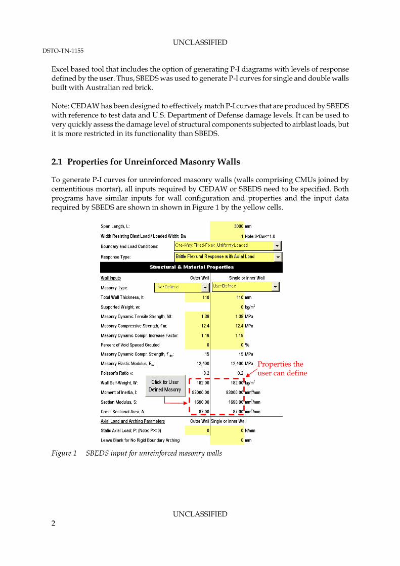
To generate P-I curves for unreinforced masonry walls (walls comprising CMUs joined by cementitious mortar), all inputs required by CEDAW or SBEDS need to be specified. Both programs have similar inputs for wall configuration and properties and the input data required by SBEDS are shown in shown in Figure 1 by the yellow cells.
Properties the user can define
Figure 1 SBEDS input for unreinforced masonry walls
UNCLASSIFIED 2
UNCLASSIFIED DSTO-TN-1155
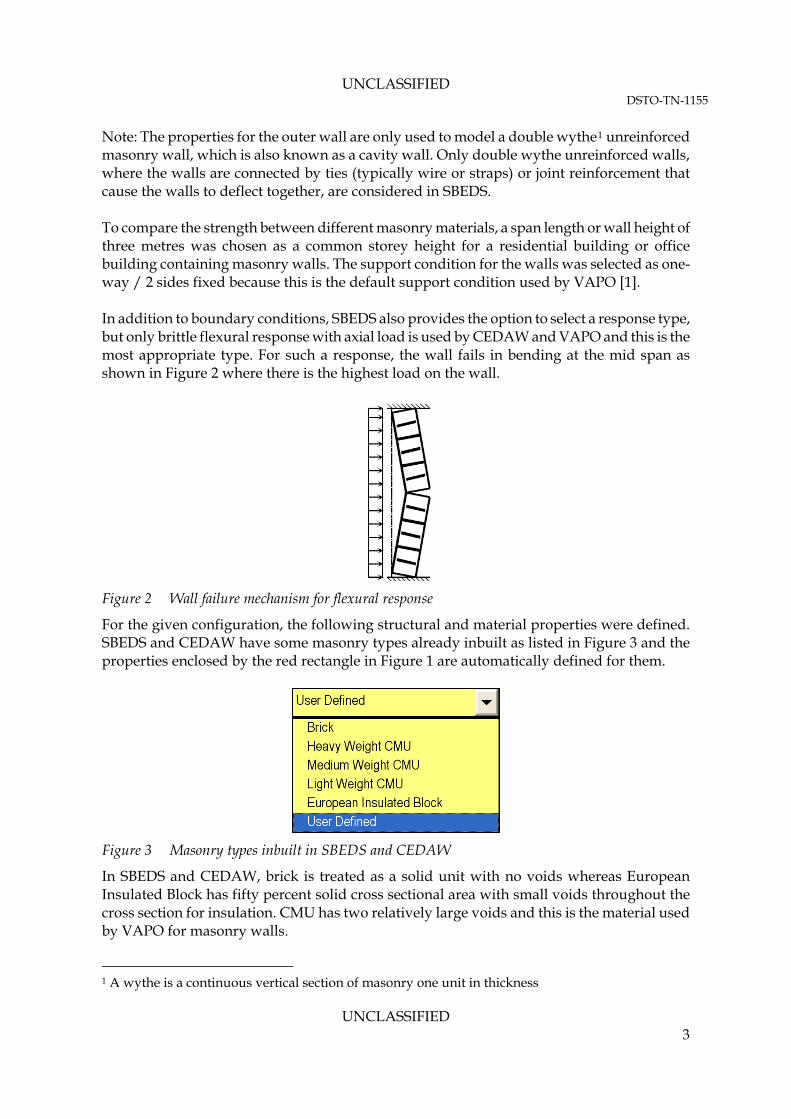
Note: The properties for the outer wall are only used to model a double wythe1 unreinforced masonry wall, which is also known as a cavity wall. Only double wythe unreinforced walls, where the walls are connected by ties (typically wire or straps) or joint reinforcement that cause the walls to deflect together, are considered in SBEDS. To compare the strength between different masonry materials, a span length or wall height of three metres was chosen as a common storey height for a residential building or office building containing masonry walls. The support condition for the walls was selected as one-way / 2 sides fixed because this is the default support condition used by VAPO [1]. In addition to boundary conditions, SBEDS also provides the option to select a response type, but only brittle flexural response with axial load is used by CEDAW and VAPO and this is the most appropriate type. For such a response, the wall fails in bending at the mid span as shown in Figure 2 where there is the highest load on the wall.
Figure 2 Wall failure mechanism for flexural response
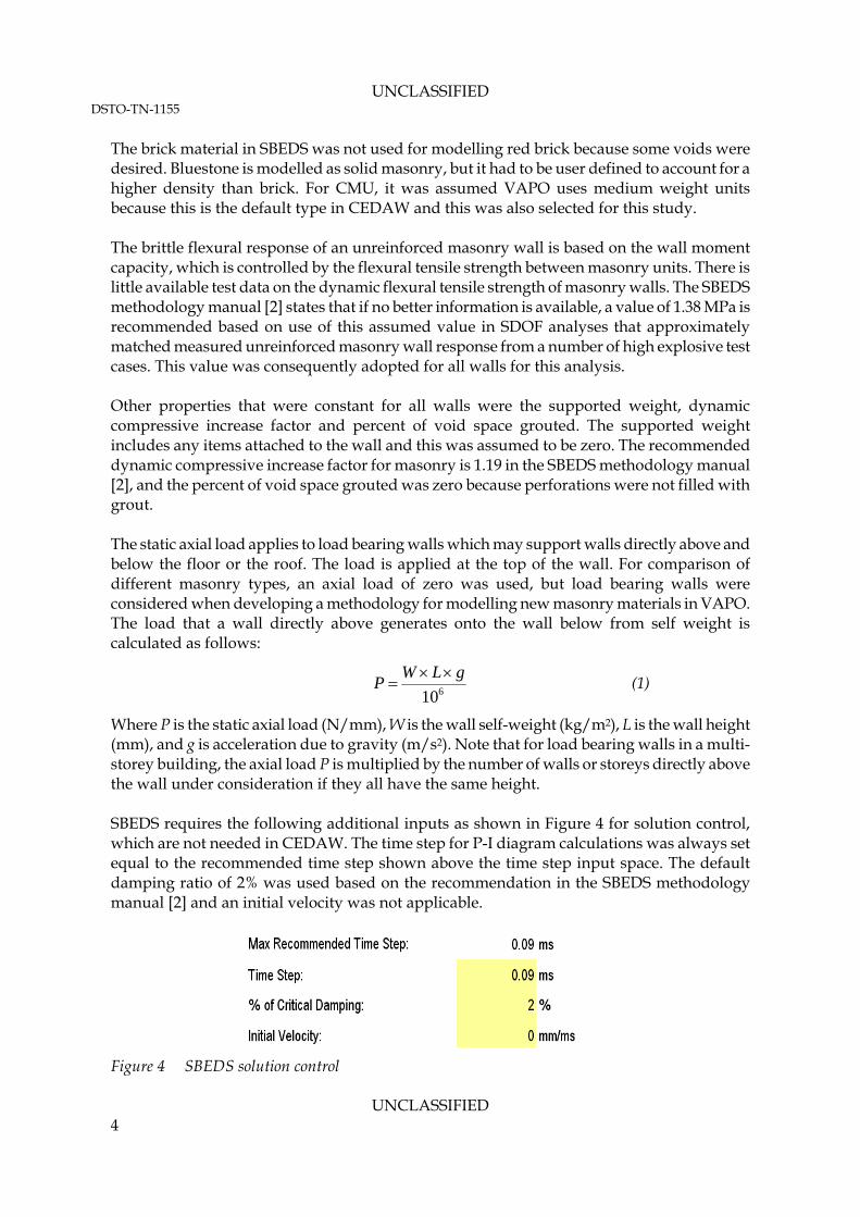
For the given configuration, the following structural and material properties were defined. SBEDS and CEDAW have some masonry types already inbuilt as listed in Figure 3 and the properties enclosed by the red rectangle in Figure 1 are automatically defined for them.
Figure 3 Masonry types inbuilt in SBEDS and CEDAW
In SBEDS and CEDAW, brick is treated as a solid unit with no voids whereas European Insulated Block has fifty percent solid cross sectional area with small voids throughout the cross section for insulation. CMU has two relatively large voids and this is the material used by VAPO for masonry walls.
1 A wythe is a continuous vertical section of masonry one unit in thickness
UNCLASSIFIED 3
UNCLASSIFIED DSTO-TN-1155
The brick material in SBEDS was not used for modelling red brick because some voids were desired. Bluestone is modelled as solid masonry, but it had to be user defined to account for a higher density than brick. For CMU, it was assumed VAPO uses medium weight units because this is the default type in CEDAW and this was also selected for this study. The brittle flexural response of an unreinforced masonry wall is based on the wall moment capacity, which is controlled by the flexural tensile strength between masonry units. There is little available test data on the dynamic flexural tensile strength of masonry walls. The SBEDS methodology manual [2] states that if no better information is available, a value of 1.38 MPa is recommended based on use of this assumed value in SDOF analyses that approximately matched measured unreinforced masonry wall response from a number of high explosive test cases. This value was consequently adopted for all walls for this analysis. Other properties that were constant for all walls were the supported weight, dynamic compressive increase factor and percent of void space grouted. The supported weight includes any items attached to the wall and this was assumed to be zero. The recommended dynamic compressive increase factor for masonry is 1.19 in the SBEDS methodology manual [2], and the percent of void space grouted was zero because perforations were not filled with grout. The static axial load applies to load bearing walls which may support walls directly above and below the floor or the roof. The load is applied at the top of the wall. For comparison of different masonry types, an axial load of zero was used, but load bearing walls were considered when developing a methodology for modelling new masonry materials in VAPO. The load that a wall directly above generates onto the wall below from self weight is calculated as follows:
610
gLWP
(1)
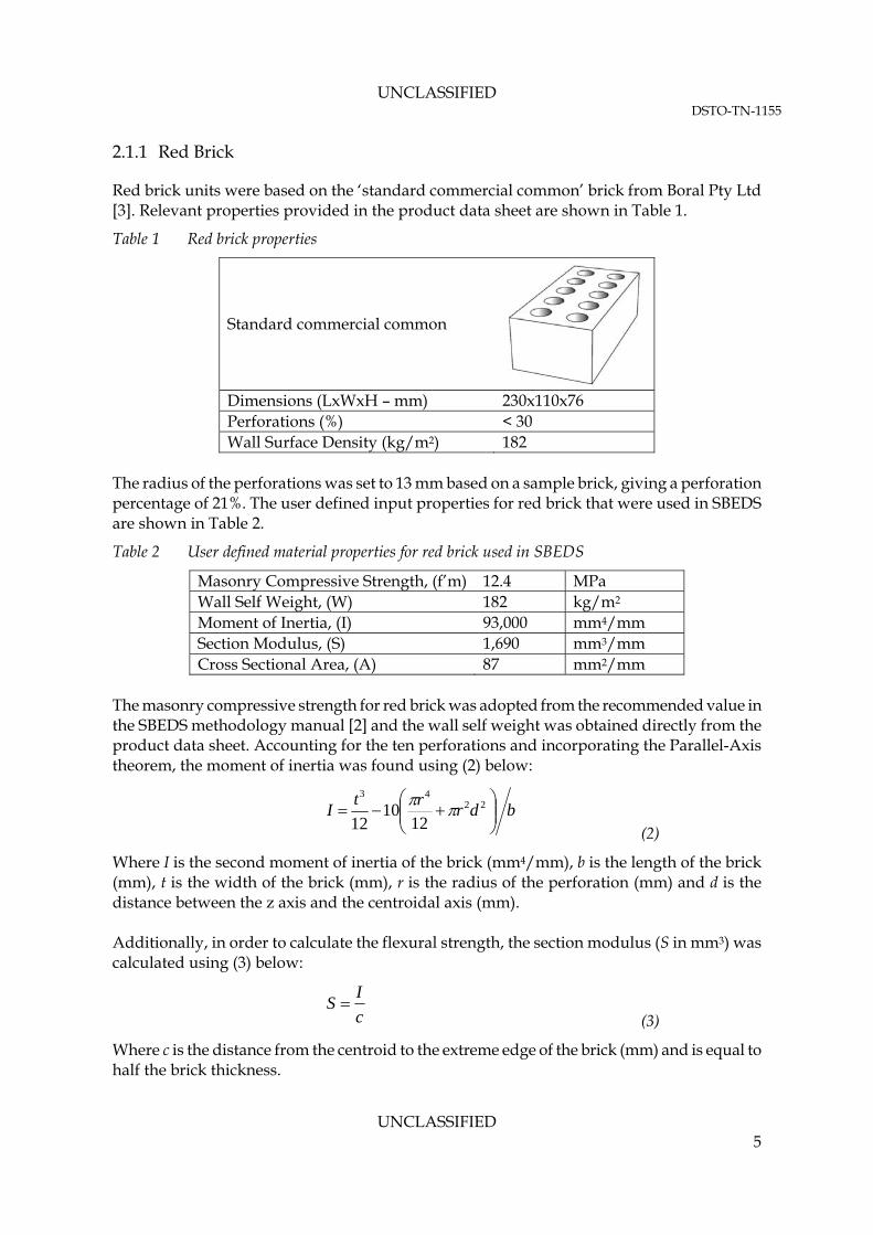
Where P is the static axial load (N/mm), W is the wall self-weight (kg/m2), L is the wall height (mm), and g is acceleration due to gravity (m/s2). Note that for load bearing walls in a multi-storey building, the axial load P is multiplied by the number of walls or storeys directly above the wall under consideration if they all have the same height. SBEDS requires the following additional inputs as shown in Figure 4 for solution control, which are not needed in CEDAW. The time step for P-I diagram calculations was always set equal to the recommended time step shown above the time step input space. The default damping ratio of 2% was used based on the recommendation in the SBEDS methodology manual [2] and an initial velocity was not applicable.
Figure 4 SBEDS solution control
UNCLASSIFIED 4
UNCLASSIFIED DSTO-TN-1155
2.1.1 Red Brick
Red brick units were based on the ‘standard commercial common’ brick from Boral Pty Ltd [3]. Relevant properties provided in the product data sheet are shown in Table 1.
Table 1 Red brick properties
Standard commercial common
Dimensions (LxWxH – mm) 230x110x76 Perforations (%) < 30 Wall Surface Density (kg/m2) 182
The radius of the perforations was set to 13 mm based on a sample brick, giving a perforation percentage of 21%. The user defined input properties for red brick that were used in SBEDS are shown in Table 2.
Table 2 User defined material properties for red brick used in SBEDS
Masonry Compressive Strength, (f’m) 12.4 MPa Wall Self Weight, (W) 182 kg/m2
Moment of Inertia, (I) 93,000 mm4/mm Section Modulus, (S) 1,690 mm3/mm Cross Sectional Area, (A) 87 mm2/mm
The masonry compressive strength for red brick was adopted from the recommended value in the SBEDS methodology manual [2] and the wall self weight was obtained directly from the product data sheet. Accounting for the ten perforations and incorporating the Parallel-Axis theorem, the moment of inertia was found using (2) below:
bdr
rtI
22
43
1210
12
(2)
Where I is the second moment of inertia of the brick (mm4/mm), b is the length of the brick (mm), t is the width of the brick (mm), r is the radius of the perforation (mm) and d is the distance between the z axis and the centroidal axis (mm). Additionally, in order to calculate the flexural strength, the section modulus (S in mm3) was calculated using (3) below:
c
IS
(3)
Where c is the distance from the centroid to the extreme edge of the brick (mm) and is equal to half the brick thickness.
UNCLASSIFIED 5
UNCLASSIFIED DSTO-TN-1155
2.1.2 Bluestone Block
Bluestone blocks were modelled as solid masonry. The thickness of the wall was set to 400mm to be consistent with relevant site investigations and the user defined input properties for bluestone blocks are shown in Table 3.
Table 3 User defined material properties for bluestone blocks used in CEDAW
Masonry Compressive Strength, (f’m) 30 MPa Wall Self Weight, (W) 1,120 kg/m2
Moment of Inertia, (I) 5,333,333 mm4/mm Section Modulus, (S) 26,667 mm3/mm Cross Sectional Area, (A) 400 mm2/mm
A conservative value for the compressive strength of stone masonry was chosen based on experimental results of Rao et al. [4] and Vasconcelos and Lourenco [5]. Note that the masonry compressive strength was expressed in terms of the prism compression strength as per the SBEDS methodology [2], which is the compressive strength of a short column of masonry material that is mortared together in a manner representative of the wall construction. The bulk density for bluestone was taken as 2,800 kg/m3 from PWGSC [6] based on the results from numerous authors and was multiplied by the wall thickness to give the wall self weight. The moment of inertia and section modulus are calculated using (4) and (5) below:
(4) 12/3tI
(5) 6/2tS
2.1.3 Concrete Masonry Unit
The material properties that are contained within CEDAW for medium weight CMU are adopted in this project. The wall thickness entered in CEDAW was 200mm to fit a standard CMU block and a recommended compressive strength of 9.3 MPa for ungrouted CMU was used [2]. 2.2 Pressure-Impulse and Charge Weight – Standoff Diagrams
A P-I curve is a curve of points representing the peak positive phase pressure and peak positive phase impulse of all blast loads causing a given maximum dynamic deflection to a given structural component. P-I diagrams in SBEDS were generated for blast loads with positive and negative phase load because this is the load type used by CEDAW and VAPO for unreinforced masonry walls. A charge weight-standoff diagram is an alternative to a P-I diagram and it shows TNT charge weight-standoff combinations that cause a given maximum deflection to a structural component. VAPO, CEDAW and SBEDS all provide the option to generate charge weight-
UNCLASSIFIED 6
UNCLASSIFIED DSTO-TN-1155
standoff diagrams and they are used in this report to give the user a better sense for the result because they relate to more easily understandable physical parameters. P-I curves for Australian red brick walls were generated specifically in SBEDS because the program allows modifying CEDAW’s response criteria [7] for P-I curves for different damage levels. Table 4 summarises the response criteria for P-I curves for each damage level and masonry type.
Table 4 Response parameter criteria for upper bound P-I curves for each U.S. Department of Defence damage level and masonry type
Ductility Ratio for
Support Rotation (o) for
Masonry Type Superficial
Damage Moderate Damage
Heavy Damage
Hazardous Failure
CMU and bluestone blocks (CEDAW)
1 1.5 4 Experiment data
Australian single and double red brick (SBEDS)
1 0.84 2.1 3.15
Support rotation, θ, is the amount the member rotates at a support location as shown in Figure 5 and is measured in degrees. The maximum displacement, Xmax, can be calculated from rotation using (6).
θ
Figure 5 Definition of support rotation
tan
2max
LX
(6)
The response criteria for red brick were modified because according to the US Army Corps of Engineers Protective Design Centre (PDC), the response of unreinforced masonry walls is also limited by the maximum member displacement to masonry thickness ratio for the above damage levels. The ratio should not be greater than 0.2, 0.5 and 0.75 for moderate damage, heavy damage and hazardous failure respectively, and this limit should be compared with the rotation limit to use the most restrictive condition [8]. For a three metre high CMU wall, the CEDAW support rotation criteria approximately follow the maximum member displacement to thickness ratio limits provided by PDC, except for the hazardous failure case. Since red brick units are typically half the thickness of CMU, the
Xmax
L/2
L/2
UNCLASSIFIED 7
UNCLASSIFIED DSTO-TN-1155
maximum member displacements to masonry thickness ratio limits are exceeded and support rotations must reduce to meet them. To satisfy the above response criteria for P-I or charge weight – standoff diagrams, SBEDS increases the time step, if necessary, to calculate response out to the time of maximum deflection. SBEDS uses a fixed number of 2900 time steps and this may not be sufficient to calculate maximum response if the time step is too small. However, a larger time step creates inaccuracies in response diagrams for high blast pressures. At higher pressures, P-I curves for blast loads with positive and negative phase should become vertically asymptotic, as explained in the SBEDS methodology manual [2], but this does not occur in some cases for walls constructed of red brick as indicated in Figure 6. Since SBEDS cautions the user with an error message, “Large Time Step/Load Duration” the P-I diagrams were manually adjusted to approach the asymptote at maximum pressure and impulse values and corresponding adjustments were made to the charge weight – standoff diagrams.
Figure 6 P-I diagram for positive and negative phase blast load from SBEDS
2.3 Modelling New Masonry in VAPO
VAPO has the functionality of being able to specify user defined P-I curves for new materials. However, this feature is not linked with Building Injury Calculator and DatabaseS (BICADS) and consequently injuries inside a building are not predicted from failure of such components.
UNCLASSIFIED 8
UNCLASSIFIED DSTO-TN-1155
User defined P-I curves give the flexibility to represent a wide range of material specifications, but those materials may be outside the scope of empirical databases leveraged by BICADS. For this reason, VAPO does not consider information about the material itself when using user defined P-I curves to deduce failure characteristics for injury predictions. Not having injury predictions from wall debris resulting from the failure of masonry walls can be considered a significant limitation since the masonry debris component of building failure has a relatively large effect on human injury and casualties results and is often the main concern as opposed to structural damage. To overcome this limitation for new materials, it is proposed that the closest available material in VAPO is chosen and then adapted to have an equivalent blast resistance of the new material. This is achieved by adjusting the specifications of the existing material so that the P-I diagram of the new material is matched as closely as possible. For masonry walls, adapting the CMU in VAPO to make it equivalent to red brick is considered a valid approximation for predicting building injuries through BICADS. Walls based on both CMU and red brick materials fail in the same way and BICADS accounts for the blast resistance and damage done to a structural component by considering P-I curves in its engineering methodology [8]. A CMU approximation for predicting building injuries from bluestone is less accurate because heavy stone masonry can experience a different failure mechanism in some cases [9] and it is likely to generate less debris which would make it deviate more from empirical data. However, in the absence of a more suitable material in VAPO, it is still considered to be a reasonable approximation, since bluestone is closely similar to CMU and accordingly its greater blast resistance is taken into account. For approximating both materials with equivalent VAPO specifications, it was checked if VAPO could automatically account for different building configurations to simplify the process of making use of them. The three most important parameter that affects the blast resistance of walls and can change for different buildings configurations are the bearing load, wall height and boundary support conditions. 2.3.1 Load Bearing Walls
In order to establish a methodology for modelling new masonry walls with bearing loads, it was important to know how VAPO calculates the support load to generate an appropriate P-I diagram to match those conditions. VAPO defines a load bearing wall as one that supports gravity loads from the level above and weighs down the walls positioned directly beneath the load bearing wall on the level below. For a slab consisting of a wood deck on wood joists or concrete deck on open web steel joists, the joists as modelled in VAPO only span in one direction as they would in an actual structure. This implies that for a rectangular building, only the external walls on two parallel sides will carry load from the joists, and they will always be the two longer sides so that the joists have a shorter span. Note that internal masonry walls are also often load bearing for this
UNCLASSIFIED 9
UNCLASSIFIED DSTO-TN-1155
type of floor/ceiling slab construction to reduce the span of the joists, and only the internal walls parallel to the external walls mentioned above will support them. Since the top level of a building typically has no masonry weight above the top of an external wall and thus the walls on two sides carry no roof load from joists, it was possible to match P-I diagrams with zero bearing load. The accuracy of derived equivalent VAPO specifications for a non load bearing wall was then checked for a load bearing case to examine if one set of adapted specifications was adequate. Load bearing walls on level one in a three storey building were considered because a three to four storey office building with masonry is relatively common if it uses a standard floor construction with supporting joists. The weight of masonry walls directly above provides the highest contribution to bearing load, so the self weight of two masonry walls was accounted for when calculating the original P-I diagram in SBEDS or CEDAW. If the resulting P-I diagram match in VAPO was considered satisfactory, then only one set of equivalent VAPO specifications based on a non load bearing wall was generated for new materials. This is because VAPO can automatically account for several different load bearing cases. However, reinforced concrete (RC) slabs in VAPO behave differently in transferring load to load bearing walls for multi-storey office buildings. VAPO considers that for a RC slab, all load bearing walls that are in contact with it will support it. However, RC slabs in a multi storey office building are not typically supported by walls but by reinforced concrete beams and columns. Consequently, masonry walls for reinforced concrete buildings are recommended to be treated as infill walls. This implies that these infill walls are non-load bearing and are supported purely by the surrounding beams and columns, so for this type of construction equivalent VAPO parameters based on non-load bearing walls are applicable. 2.3.2 Support Conditions
In order to assess the lateral resistance of masonry walls, it is necessary to take into account the support conditions at the wall perimeter edges. A simply supported edge is one that, when a wall is loaded, lateral support at the edge is provided and this is shown in Figure 7. For a fixed edge, additional support is provided that prevents rotation at the edge occurring. This rotation is seen at the bottom of the wall in Figure 7.
UNCLASSIFIED 10
UNCLASSIFIED DSTO-TN-1155
Figure 7 Supports for flexural failure mode of a wall subject to lateral loading
For a multi-storey building, a fixed support condition for masonry walls is recommended because the weight of walls from upper floors will restrain the walls on lower floors from rotating at the top and bottom wall edges. However, for a single story building, there is no rotational restraint at the top edge from upper floors and only lateral supports are likely to be present at the top and bottom edges. Therefore, a simple boundary condition is recommended. With these support conditions, masonry walls are usually not analysed for two-way flexural response where vertical edges are supported in addition to the top and bottom edges. This is because there is usually a weak connection between the wall and adjacent vertical supports and because the vertical span is often much less than the horizontal span so that most of the wall strength and stiffness is provided by the vertical span.
3. Results
The blast resistance of new masonry wall materials are first compared and the effects of variables that affect the blast resistance of masonry walls for different building types are presented. Equivalent VAPO specifications that enable the modelling of the new masonry wall types for a range of building types are then provided. 3.1 Comparison of Wall Strengths
A comparison of heavy damage P-I curves and corresponding reflected pressure charge weight – standoff curves for walls constructed from single and double red brick, CMU and bluestone blocks are shown in Figure 8 and Figure 9 respectively. The results show that walls constructed from double red brick and CMU have similar blast resistance. Referring to Figure 8, the CMU wall is stronger at points (1) and (2) because it has a larger bending capacity, but this is balanced at point (3) because a double red brick wall has a greater mass.
UNCLASSIFIED 11
UNCLASSIFIED DSTO-TN-1155
UNCLASSIFIED 12
Figure 9 gives a practical indication of the reduction in blast resistance for single red brick walls. Bluestone is immensely stronger than the other masonry types because it is considerably thicker with a larger mass and the bending capacity for solid masonry is dependent on the thickness squared. 3.1.1 Load Bearing Walls
The effect of bearing load on a double red brick wall is shown in Figure 10 and similar effects occur for other masonry wall types. The example shown is the case for a three storey building where the wall on level one supports two upper floor walls and the wall on level three is non load bearing. It can be seen from the result that as expected the presence of a bearing load increases a wall’s blast resistance and that this effect becomes more significant with increasing explosive charge standoff distances. 3.1.2 Effect of Boundary Support Conditions
The effect of having a simple boundary condition for double red brick walls is shown in Figure 11. The result shows that a wall with simple boundary conditions has a significantly lower blast resistance for larger standoff distances and the other masonry wall types show similar trends. 3.1.3 Effect of Wall Height
The results show that a higher wall generally suffers more damage at larger standoff distances. This is quantified in Figure 12 for double red brick by comparing a three and four metre high wall. Similar trends are shown for the other masonry wall types considered.
UNCLASSIFIED DSTO-TN-1155
3
2
1
Figure 8 Heavy damage pressure-impulse diagram comparisons for different unreinforced masonry wall types
UNCLASSIFIED 13
UNCLASSIFIED DSTO-TN-1155
Figure 9 Heavy damage reflected pressure charge weight – standoff diagram comparisons for different unreinforced masonry wall types
UNCLASSIFIED 14
UNCLASSIFIED DSTO-TN-1155
Figure 10 Effect of a load bearing double red brick wall supporting two walls directly above from upper floors on blast resistance
UNCLASSIFIED 15
UNCLASSIFIED DSTO-TN-1155
Figure 11 Reflected pressure charge weight – standoff diagram comparison of simple and fixed boundary support conditions for double red brick walls
UNCLASSIFIED 16
UNCLASSIFIED DSTO-TN-1155
UNCLASSIFIED 17
Figure 12 Reflected pressure charge weight – standoff diagram comparison of 3m and 4m high double red brick walls
UNCLASSIFIED DSTO-TN-1155
3.2 VAPO Specifications for New Masonry
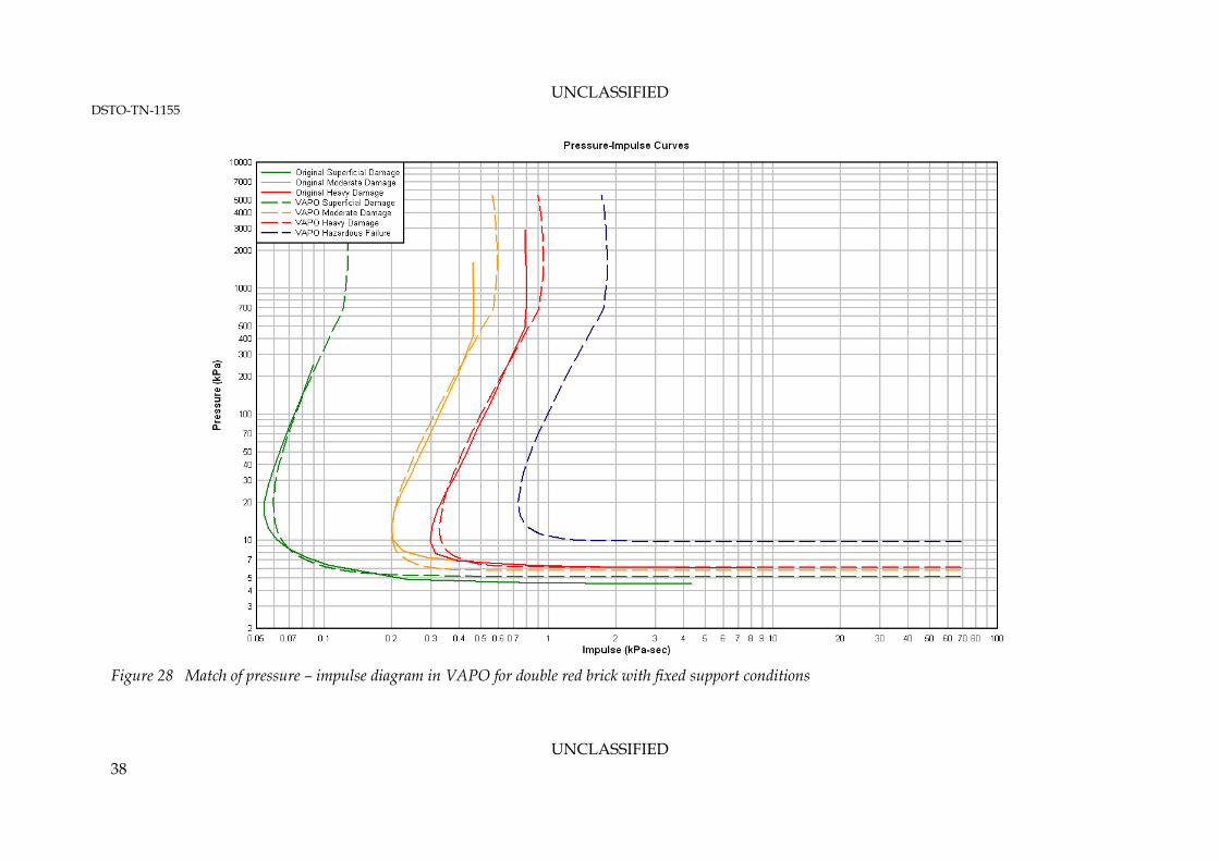
Adapted VAPO properties for new masonry materials are presented in this section and their performance in generating equivalent wall strength is compared. The comparisons are presented using charge weight-standoff diagrams and corresponding P-I diagrams are included in the Appendix. The curves within the diagrams are an upper bound so the damage levels are applicable below the curves. It should be noted that it was not possible for VAPO to accurately match one of the damage level curves for red brick walls. This is because the response criteria for red brick had to be modified as explained in Section 2.2 and the criterion from PDC for hazardous failure is too conservative. The discrepancy can be seen in the Appendix. The curve for hazardous failure in VAPO is based on experimental data of CMU and units of similar thickness instead of the PDC criterion, because it is more accurate. No such experimental information was available for red brick, but to improve the PDC criterion, experimental data was approximated by assuming the P-I curve for hazardous failure was the same as that which VAPO calculates with the adapted specifications. 3.2.1 Single Red Brick Walls
Adapted VAPO specifications for walls constructed from single red brick with fixed and simple boundary support conditions are presented in Figure 13 and Figure 14 respectively. The corresponding match of single red brick in VAPO is shown in Figure 18 and Figure 19 respectively and the results are considered acceptable. Note that for a brick veneer structure, wood or steel studs typically carry the load from the floor and the roof and the exterior brick walls are non load bearing. Structures using single red brick walls are modelled individually and VAPO requires external walls to be load bearing for a structure to be stable.
UNCLASSIFIED 18
UNCLASSIFIED DSTO-TN-1155
One-Way: Fixed-Fixed
Figure 13 Adapted VAPO specifications for single red brick walls with fixed support conditions
One-Way: Simple-Simple
Figure 14 Adapted VAPO specifications for single red brick walls with simple support conditions
3.2.2 Double Red Brick Walls
Adapted VAPO specifications for walls constructed from double red brick with fixed and simple boundary support conditions are presented in Figure 15 and Figure 16 respectively. The corresponding match of this material in VAPO is shown in Figure 20 and Figure 21 respectively and the match is considered acceptable.
UNCLASSIFIED 19
UNCLASSIFIED DSTO-TN-1155
One-Way: Fixed-Fixed
Figure 15 Adapted VAPO specifications for double red brick walls with fixed support conditions
One-Way: Simple-Simple
Figure 16 Adapted VAPO specifications for double red brick walls with simple support conditions
3.2.3 Bluestone Block Walls
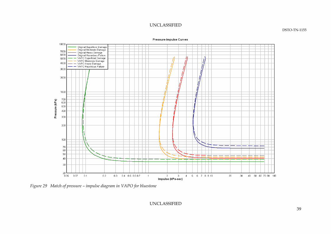
Adapted VAPO specifications for bluestone block walls are presented in Figure 17 and the corresponding match for this material is shown in Figure 22. Note that in the methodology it is explained that bluestone walls have fixed boundary support conditions, but VAPO gives a better match if simply supported conditions are used in the adapted specifications.
UNCLASSIFIED 20
UNCLASSIFIED DSTO-TN-1155
UNCLASSIFIED 21
One-Way: Simple-Simple
Figure 17 Adapted VAPO specifications for bluestone block walls
UNCLASSIFIED DSTO-TN-1155
Figure 18 Match of reflected pressure charge weight – standoff diagram in VAPO for single red brick walls with fixed support conditions
UNCLASSIFIED 22
UNCLASSIFIED DSTO-TN-1155
Figure 19 Match of reflected pressure charge weight – standoff diagram in VAPO for single red brick walls with simple support conditions
UNCLASSIFIED 23
UNCLASSIFIED DSTO-TN-1155
Figure 20 Match of reflected pressure charge weight – standoff diagram in VAPO for double red brick walls with fixed support conditions
UNCLASSIFIED 24
UNCLASSIFIED DSTO-TN-1155
Figure 21 Match of reflected pressure charge weight – standoff diagram in VAPO for double red brick walls with simple support conditions and adapted
specifications
UNCLASSIFIED 25
UNCLASSIFIED DSTO-TN-1155
UNCLASSIFIED 26
Figure 22 Match of reflected pressure charge weight – standoff diagram for bluestone block walls with adapted VAPO specifications
UNCLASSIFIED DSTO-TN-1155
3.2.4 Performance for Load Bearing Walls
The performance of adapted VAPO specifications for a load bearing double red brick wall is presented in Figure 23. The match to the original blast response is excellent for superficial and moderate damage, but VAPO somewhat overestimates heavy damage. Since bluestone walls are significantly heavier than CMU, the performance of adapted VAPO specifications for a load bearing bluestone wall is also presented in Figure 24. Only a moderate discrepancy for superficial damage is observed. Overall, it is considered sufficient to have one set of adapted VAPO specifications for load bearing walls because the majority of the results match reasonably accurately. Otherwise, the management of different specifications for different storeys becomes difficult and wall specifications would have to be changed manually each time in VAPO for each corresponding storey. 3.2.5 Performance for Different Wall Height
The performance of adapted VAPO specifications for a four metre high wall instead of the original three metres is presented in Figure 25. It can be seen that the match to the original material is excellent for larger standoff distances, but there is some moderate discrepancy at smaller distances for two damage levels. Overall, the performance is considered satisfactory since the wall height is likely to be less than four metres and the match to the original material would only be improved. Note that the wall height is based on the clear height in VAPO, which is the storey height minus the slab thickness and this further improves performance for a concrete slab.
UNCLASSIFIED 27
UNCLASSIFIED DSTO-TN-1155
Figure 23 Performance of adapted VAPO specifications for double red brick walls on level one in a three storey building
UNCLASSIFIED 28
UNCLASSIFIED DSTO-TN-1155
Figure 24 Performance of adapted VAPO specifications for bluestone block walls on level one in a three storey building
UNCLASSIFIED 29
UNCLASSIFIED DSTO-TN-1155
UNCLASSIFIED 30
Figure 25 Performance of adapted VAPO specifications for a four metre high double red brick wall
UNCLASSIFIED DSTO-TN-1155
4. Summary
SDOF analyses were performed to generate response data for characterising the response of single and double red brick and bluestone block walls to explosive blast loads. The data was plotted as P-I and charge weight – standoff charts, which provide a fast running model used by VAPO in assessing the wall’s response to this loading To implement the new materials in VAPO, specifications of existing materials were adapted to generate an equivalent blast response. The specifications were developed considering various building types to encompass different bearing loads, boundary support conditions and wall heights. The application of new masonry walls to different building types is summarised below and is based on the methodology explained in Section 2.3
i. Single red brick – applies to external walls
For one storey building, use specifications in Figure 14: single red brick walls with simple supports
For two storey building, use specifications in Figure 13: single red brick walls with fixed supports
ii. Double red brick with cavity– applies to external and internal walls
For one storey building, use specifications in Figure 16 with load bearing option: double red brick walls with simple supports
For multi-storey building with floor joists, use specifications in Figure 15 with load bearing option: double red brick walls with fixed supports
For multi-storey building with reinforced concrete floors, use specifications in Figure 15 without load bearing option: double red brick walls with fixed supports
iii. Bluestone blocks – applies to external and internal walls
For multi-storey building with floor joists, use specifications in Figure 17 with load bearing option
For multi-storey building with reinforced concrete floors, use specifications in Figure 17 without load bearing option.
For a brick veneer building, the internal walls are likely to be studs, but the above points also apply to single brick internal walls. In addition to the above materials, the following specifications can be used for solid masonry walls consisting of red brick with no cavities. These walls have been encountered in a relevant heritage building and were up to 500mm thick. Note that these masonry units are approximated as solid bricks with no perforations.
UNCLASSIFIED 31
UNCLASSIFIED DSTO-TN-1155
iv. Solid red brick without cavity – applies to external and internal walls
Referring to the wall specification sheet for unreinforced block, set material strength to 12.4 MPa, wall thickness to real value and void ratio to zero. Shell thickness is obsolete for solid brick and can be left as is.
For multi-storey building with floor joists, use load bearing option
Use one-way: fixed-fixed boundary support conditions.
UNCLASSIFIED 32
UNCLASSIFIED DSTO-TN-1155
5. References
1. DTRA, Engineering Methodology Report, CEDAW, VAPO Ver 4.0, 2009 (Rev 5). 2. USACE PDC, Methodology Manual for the Single-Degree-of-Freedom Blast Effects
Design Spreadsheets (SBEDS), 2008. 3. Boral, Bricks & Pavers Technical Manual, 2004. 4. K. V. M. Rao, B. V. V. Reddy and K. S. Jagadish, “Strength characteristics of stone
masonry,” Materials and Structures, vol. 30, pp. 233-237, 1997. 5. G. Vasconcelos and P. B. Lourenco, “Experimental characterization of stone masonry
in shear and compression,” Construction and Building Materials, vol. 23, pp. 3337-3345, 2009.
6. Public Works & Government Services Canada (PWGSC), Guidelines for the Seismic Assessment of Stone-Masonry Structures, 2000.
7. USACE PDC, Methodology Manual for Component Explosive Damage Assessment Workbook (CEDAW), 2008.
8. DTRA, Engineering Methodology Report, BICADS, VAPO Ver 4.0, 2009 (Rev 5). 9. J. Crawford, S. Lan and H. Choi, Quantity-Distance Curves for Determining the Blast
Resistance of Heavy Masonry Walls, K&C, 2004.
UNCLASSIFIED 33
UNCLASSIFIED DSTO-TN-1155
UNCLASSIFIED 34
This page is intentionally blank
UNCLASSIFIED DSTO-TN-1155
Appendix A: Amended Results
Figure 26 Discrepancy in VAPO for hazardous failure using the PDC response criterion for double red brick
UNCLASSIFIED 35
UNCLASSIFIED DSTO-TN-1155
This page is intentionally blank
UNCLASSIFIED 36
UNCLASSIFIED DSTO-TN-1155
Appendix B: P-I Diagrams
Figure 27 Match of pressure – impulse diagram in VAPO for single red brick with fixed support conditions
UNCLASSIFIED 37
UNCLASSIFIED DSTO-TN-1155
Figure 28 Match of pressure – impulse diagram in VAPO for double red brick with fixed support conditions
UNCLASSIFIED 38
UNCLASSIFIED DSTO-TN-1155
UNCLASSIFIED 39
Figure 29 Match of pressure – impulse diagram in VAPO for bluestone
Page classification: UNCLASSIFIED
DEFENCE SCIENCE AND TECHNOLOGY ORGANISATION
DOCUMENT CONTROL DATA 1. PRIVACY MARKING/CAVEAT (OF DOCUMENT)
2. TITLE Modelling Australian Red Brick and Bluestone Walls in VAPO
3. SECURITY CLASSIFICATION (FOR UNCLASSIFIED REPORTS THAT ARE LIMITED RELEASE USE (L) NEXT TO DOCUMENT CLASSIFICATION) Document (U) Title (U) Abstract (U)
4. AUTHOR(S) Matthew Lukaszewicz and Christine Pienaar
5. CORPORATE AUTHOR DSTO Defence Science and Technology Organisation PO Box 1500 Edinburgh South Australia 5111 Australia
6a. DSTO NUMBER DSTO-TN-1155
6b. AR NUMBER AR-015-509
6c. TYPE OF REPORT Technical Report
7. DOCUMENT DATE January 2013
8. FILE NUMBER 2013/1007439/1
9. TASK NUMBER NS 07/002
10. TASK SPONSOR Defence Security Authority
11. NO. OF PAGES 39
12. NO. OF REFERENCES 9
13. DSTO Publications Repository http://dspace.dsto.defence.gov.au/dspace/
14. RELEASE AUTHORITY Chief, Weapons Systems Division
15. SECONDARY RELEASE STATEMENT OF THIS DOCUMENT
Approved for public release OVERSEAS ENQUIRIES OUTSIDE STATED LIMITATIONS SHOULD BE REFERRED THROUGH DOCUMENT EXCHANGE, PO BOX 1500, EDINBURGH, SA 5111 16. DELIBERATE ANNOUNCEMENT No Limitations 17. CITATION IN OTHER DOCUMENTS Yes 18. DSTO RESEARCH LIBRARY THESAURUS Blast Effects, Structures, Modelling 19. ABSTRACT To confidently predict structural and building damage due to explosive blast loads, Threat Mitigation Group, Weapons Systems Division, is comparing, improving and validating existing modelling tools. For conventional structures, the Vulnerability Assessment and Protection Options (VAPO) software, a product of the Defense Threat Reduction Agency (DTRA), is DSTO's primary effects prediction software tool due to the rapidity with which an analysis can be conducted and the ability of the software to predict potential human casualties due to blast or building debris. VAPO is well-suited to model and analyse complex urban scenarios but lacks the ability to model certain Australian building materials. This report provides details on how to input material engineering data for structures with walls composed of Australian Standard size single and double red brick as well as bluestone building blocks. The response of these materials to blast loads was determined through a single degree of freedom analysis which represented a dynamically equivalent system.
Page classification: UNCLASSIFIED