Embed Size (px)
Citation preview
Page: 1/7
ABSTRACT
This document sets out the study and process performed to develop a tool to simulate firetube boilers, as well as the modelling of the various operating modes. The development of this tool is based on the creation of an EcosimPro library that includes the components to be used for the modelling of the steam generating system in a firetube boiler. Thanks to its capacity to link an experiment with Excel, it will be possible to create a simple and intuitive interface for the end user.
Finally, several experiments have been performed to
obtain results under the different operating modes. This will yield values of the temperature profiles, the evolution of the pressure, flow, etc, that allows some components of the firetube boiler to be designed.
The document is structured into an introduction, a
model description, modelling, simulation, result verification, Excel interface development and conclusions.
Keywords: modelling, simulation, firetube boiler, steam generation, EcosimPro.
Note: this document has been created as a summary of the DFP with the same title, as developed by the author. Please contact Empresarios Agrupados if you wish to check said DFP.
LIST OF VARIABLES AND ACRONYMS
DFP Degree final project
MCR Maximum Continuous Rating MNR Minimum Nominal Rating
P Pressure of the steam chamber inside the boiler
T Temperature of the component it refers to
level Level of liquid in the container containing the water
m Mass flow of the current it refers to
q Exchanged useful heat flow
1 INTRODUCTION
For centuries, many civilisations have been attracted to the energy that is released by steam when it condenses. Nowadays, many industrial processes require the transfer of heat released from a combustion process to different fluids so they can be used in different states (steam, superheated water, heat fluid). The use of boilers therefore becomes indispensable.
The energy consumed in these boilers is one of the
most important industrial consumers, so it is extremely important to take measures to improve the energy efficiency and thus improve the competitiveness of the industry in question. It is also important to perform a numerical simulation to obtain results that shed light on the properties of the various components by modifying some of the design parameters of the boilers.
In recent years, programs using object-oriented
modelling have gained the upper hand in the market. The main advantage of this type of software is the possibility of encapsulating the equations governing a system by writing on the components that form it (much in the same way as with the analytical method), so that the program can later rearrange them to solve them as necessary. This significantly eases the reuse of components to form other systems and modify the component modelling.
EcosimPro is a program that uses this approach to
simulation. The great simulation flexibility of EcosimPro and the simplicity of the modelling are offset by the program’s initial complexity for new users. Its learning curve is steep. In EcosimPro, the possibility of generating experiments is extremely important, since these may be used by beginners to perform simulations.
The capacities of EcosimPro have been used in this
project to create a tool, encapsulated within an experiment with a new component, firetube boiler, to perform the simulation of the various operating modes (continuous and standby).
MODELLING AND SIMULATION OF FIRETUBE BOILERS WITH ECOSIMPRO: ANALYSIS OF CONTINUOUS AND STAND-BY OPERATION
Author: David Serna Pérez [email protected]
Teaching mentor: Dr. Julio Fco. San José Alonso Escuela Ingenierías Industriales
Universidad de Valladolid In-house mentor: Almudena Rueda Ferreiro
[email protected] Empresarios Agrupados
Modelling and simulation of firetube boilers with EcosimPro: analysis of continuous and stand-by operation. Serna Pérez, David
Page: 2/7
The FLUIDAPRO library has been used as a reference to create the new component, and some components of this library have been used to model other auxiliary elements.
The generation of DECKS (1) and the connection of an experiment with EXCEL (2) serve to create an intuitive and easy interface of the model so that users can complete simulations without having specific knowledge of EcosimPro.
2 MODEL DESCRIPTION
These are the boilers where combustion gases flow within the pipes and the liquid is held in a container crossed by those pipes.
The boiler that is to be simulated is an auxiliary three-pass firetube boiler from a combined power plant that is used to produce steam. Under normal conditions, the steam is produced by the HRSGs, but whenever there is an outage, scheduled or otherwise, the steam needs to be supplied from this boiler. It is therefore important to simulate this system, to see the evolution of the temperature during start-ups and the behaviour of all the boiler elements, since a high number of startup and shutdown cycles can cause thermal fatigue in the boiler tubes over the years.
This paper simulates different operating modes, so
the following modes have been created:
• CONTINUOUS OPERATION
– MCR (Maximum Continuous Rating)
– MNR (Minimum Nominal Rating)
• HOT STAND-BY
– Recirculation
– Steam Feed
The MCR operating mode corresponds to the maximum continuous rating from the boiler. The MNR operating mode, on the other hand, is the minimum continuous nominal rating of the boiler. This rating coincides with 25% of the MCR, so both operating modes can be simulated with the same model.
The situation is different for the other stand-by
modes: a model needs to be created for each mode. Thus, the steam supply mode involves supplying the boiler with steam from the network produced by the HRSG. This supply is intermittent and only produces an inflow of steam when the pressure sensor detects a pressure drop within the boiler below the lower limit (-10%), and the valve shall remain open until the upper pressure limit within the chamber (+10%) is reached. There is a pressure drop within the steam chamber that is caused by the loss of heat through the shell and the tubes and causes the steam to condense.
The recirculation mode involves setting the burner to its lowest setting, so that the boiler will produce a small amount of steam. This steam is channelled back to the feed tank. Because of the size of this tank and of the heat losses, the steam condenses and again becomes the liquid that feeds the boiler, so it is fed back with the feed pump.
3 MODELLING
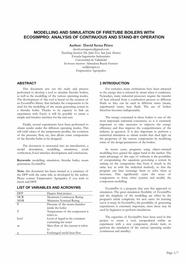
The first step in the modelling of this system is the
creation of a new component to simulate the firetube
boiler to model this system. The EcosimPro
programming language is used for the formulation of this
main component. The potential of this tool allows
inheritance to be used to define the tank where the two
phases of the fluid in equilibrium are kept. An already-
validated FLUIDAPRO component called Capacity is
used, and the tubes inside the container are added in the
TOPOLOGY section of the code with the components:
Tubes (FLUIDAPRO library) for the inner volume of the
combustion gas pipes and Cylinder (THERMAL library) to
model the pipe walls (see figure 1).
Figure 1. Diagram of the topological construction of
the Boiler component
Once the new component for the modelling of the
firetube boiler has been completed it will be possible to
add different auxiliary elements to model the various
operating modes.
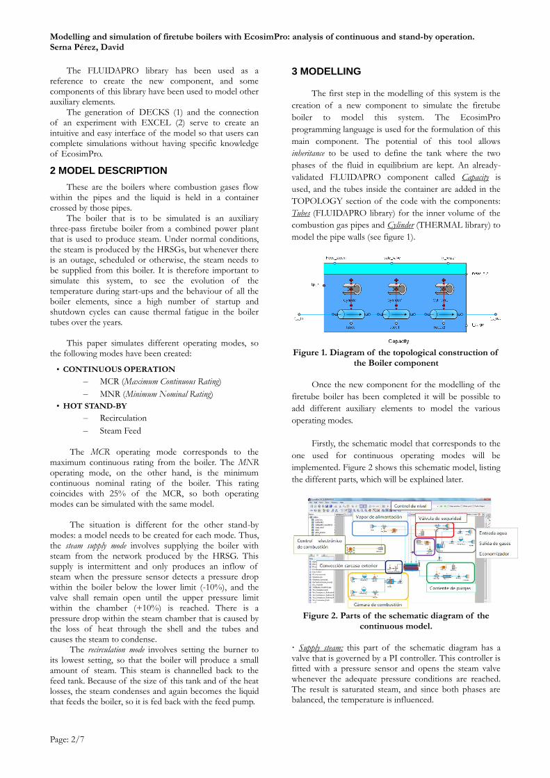
Firstly, the schematic model that corresponds to the
one used for continuous operating modes will be
implemented. Figure 2 shows this schematic model, listing
the different parts, which will be explained later.
Figure 2. Parts of the schematic diagram of the
continuous model.
· Supply steam: this part of the schematic diagram has a valve that is governed by a PI controller. This controller is fitted with a pressure sensor and opens the steam valve whenever the adequate pressure conditions are reached. The result is saturated steam, and since both phases are balanced, the temperature is influenced.
Modelling and simulation of firetube boilers with EcosimPro: analysis of continuous and stand-by operation. Serna Pérez, David
Page: 3/7
· Level control: a metering port of the main component is used to measure the liquid head inside, as explained above in the description of the Boiler component. The sensor then transforms it into an analogue signal that uses the PI controller to control the water inlet flow and therefore control the liquid level, since it is important for all the tubes to be immersed in water. · Safety valve: a pressure regulating valve uses the same signal from the sensor to open when a given percentage of the steam pressure required to relieve the overpressure is reached. The environment, where this pressure relief valves discharges into, is considered a boundary condition in this section. · Economiser : the water inlet to the boiler and the flue gas outlet is defined in this part. This type of boiler uses the outlet gas enthalpy to preheat the water that is introduced into the boiler. This heat exchange occurs in the economiser in this section. · Blowdown current: a continuous blowdown, which has been calculated beforehand, is required. This blowdown will depend on the boiler feedwater conditions and the admissible water characteristics that are set out in standard UNE 9-075-92. In this case, the data from the example are taken and a continuous blowdown of 13.85% of the boiler rating is defined (a condition that has been incorporated into the experiments). · Combustion chamber: the two fluids that are used in this process are defined by the boundary conditions and selecting the working fluid (WorkingFluid). The reactor inlet is regulated by means of two valves that are controlled to attain the required steam rating. This process is completed in the section known as electronic combustion control. This component ensures the combustion once the required conditions of the mixture are reached. · Shell-outside convection: this section defines the outer wall of the shell that protects against the environment. This transmission is not implemented in the main component (there is only wall internal convection), but this thermal port allows this phenomenon to be incorporated by means of components of the Thermal library. · Electronic combustion control: this section is very simple: it only includes a sensor that measures the steam flow and sends it to the PI controller, which compares it with the required rating and actuates on the valve controlling the reactor flow.
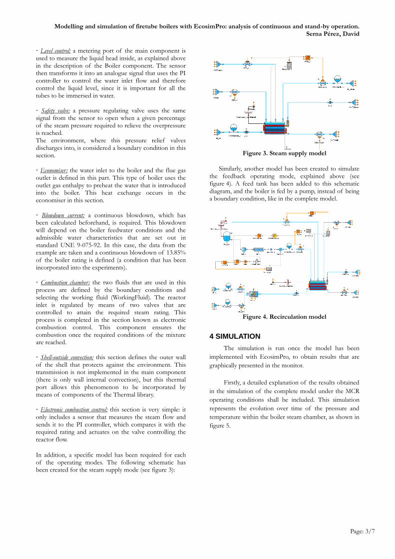
In addition, a specific model has been required for each of the operating modes. The following schematic has been created for the steam supply mode (see figure 3):
Figure 3. Steam supply model
Similarly, another model has been created to simulate the feedback operating mode, explained above (see figure 4). A feed tank has been added to this schematic diagram, and the boiler is fed by a pump, instead of being a boundary condition, like in the complete model.
Figure 4. Recirculation model
4 SIMULATION
The simulation is run once the model has been
implemented with EcosimPro, to obtain results that are
graphically presented in the monitor.
Firstly, a detailed explanation of the results obtained
in the simulation of the complete model under the MCR
operating conditions shall be included. This simulation
represents the evolution over time of the pressure and
temperature within the boiler steam chamber, as shown in
figure 5.
Modelling and simulation of firetube boilers with EcosimPro: analysis of continuous and stand-by operation. Serna Pérez, David
Page: 4/7
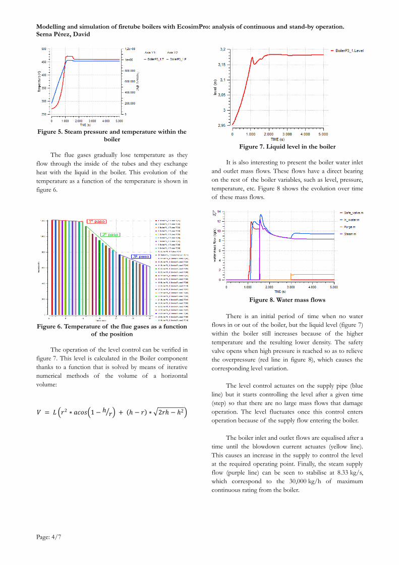
Figure 5. Steam pressure and temperature within the
boiler
The flue gases gradually lose temperature as they
flow through the inside of the tubes and they exchange
heat with the liquid in the boiler. This evolution of the
temperature as a function of the temperature is shown in
figure 6.
Figure 6. Temperature of the flue gases as a function
of the position
The operation of the level control can be verified in
figure 7. This level is calculated in the Boiler component
thanks to a function that is solved by means of iterative
numerical methods of the volume of a horizontal
volume:
𝑉 = 𝐿 𝑟2 ∗ 𝑎𝑐𝑜𝑠 1 − ℎ𝑟 + ℎ − 𝑟 ∗ 2𝑟ℎ − ℎ2
Figure 7. Liquid level in the boiler
It is also interesting to present the boiler water inlet
and outlet mass flows. These flows have a direct bearing
on the rest of the boiler variables, such as level, pressure,
temperature, etc. Figure 8 shows the evolution over time
of these mass flows.
Figure 8. Water mass flows
There is an initial period of time when no water
flows in or out of the boiler, but the liquid level (figure 7)
within the boiler still increases because of the higher
temperature and the resulting lower density. The safety
valve opens when high pressure is reached so as to relieve
the overpressure (red line in figure 8), which causes the
corresponding level variation.
The level control actuates on the supply pipe (blue
line) but it starts controlling the level after a given time
(step) so that there are no large mass flows that damage
operation. The level fluctuates once this control enters
operation because of the supply flow entering the boiler.
The boiler inlet and outlet flows are equalised after a
time until the blowdown current actuates (yellow line).
This causes an increase in the supply to control the level
at the required operating point. Finally, the steam supply
flow (purple line) can be seen to stabilise at 8.33 kg/s,
which correspond to the 30,000 kg/h of maximum
continuous rating from the boiler.
Modelling and simulation of firetube boilers with EcosimPro: analysis of continuous and stand-by operation. Serna Pérez, David
Page: 5/7
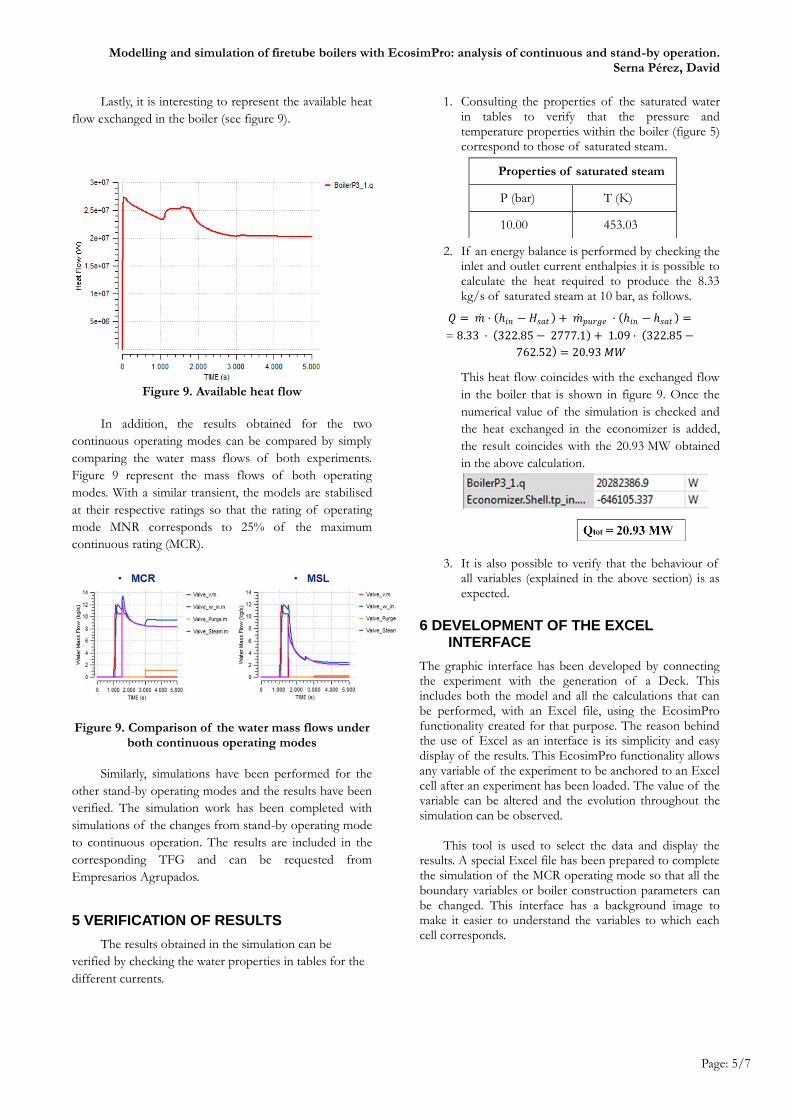
Lastly, it is interesting to represent the available heat
flow exchanged in the boiler (see figure 9).
Figure 9. Available heat flow
In addition, the results obtained for the two
continuous operating modes can be compared by simply
comparing the water mass flows of both experiments.
Figure 9 represent the mass flows of both operating
modes. With a similar transient, the models are stabilised
at their respective ratings so that the rating of operating
mode MNR corresponds to 25% of the maximum
continuous rating (MCR).
Figure 9. Comparison of the water mass flows under both continuous operating modes
Similarly, simulations have been performed for the
other stand-by operating modes and the results have been
verified. The simulation work has been completed with
simulations of the changes from stand-by operating mode
to continuous operation. The results are included in the
corresponding TFG and can be requested from
Empresarios Agrupados.
5 VERIFICATION OF RESULTS
The results obtained in the simulation can be
verified by checking the water properties in tables for the
different currents.
1. Consulting the properties of the saturated water in tables to verify that the pressure and temperature properties within the boiler (figure 5) correspond to those of saturated steam.
2. If an energy balance is performed by checking the
inlet and outlet current enthalpies it is possible to calculate the heat required to produce the 8.33 kg/s of saturated steam at 10 bar, as follows.
𝑄 = 𝑚 · ℎ𝑖𝑛 − 𝐻𝑠𝑎𝑡 + 𝑚 𝑝𝑢𝑟𝑔𝑒 · ℎ𝑖𝑛 − ℎ𝑠𝑎𝑡 =
= 8.33 · 322.85 − 2777.1 + 1.09 · 322.85 −
762.52 = 20.93 𝑀𝑊
This heat flow coincides with the exchanged flow
in the boiler that is shown in figure 9. Once the
numerical value of the simulation is checked and
the heat exchanged in the economizer is added,
the result coincides with the 20.93 MW obtained
in the above calculation.
3. It is also possible to verify that the behaviour of all variables (explained in the above section) is as expected.
6 DEVELOPMENT OF THE EXCEL INTERFACE
The graphic interface has been developed by connecting the experiment with the generation of a Deck. This includes both the model and all the calculations that can be performed, with an Excel file, using the EcosimPro functionality created for that purpose. The reason behind the use of Excel as an interface is its simplicity and easy display of the results. This EcosimPro functionality allows any variable of the experiment to be anchored to an Excel cell after an experiment has been loaded. The value of the variable can be altered and the evolution throughout the simulation can be observed.
This tool is used to select the data and display the results. A special Excel file has been prepared to complete the simulation of the MCR operating mode so that all the boundary variables or boiler construction parameters can be changed. This interface has a background image to make it easier to understand the variables to which each cell corresponds.
Properties of saturated steam
P (bar) T (K)
10.00 453.03
Modelling and simulation of firetube boilers with EcosimPro: analysis of continuous and stand-by operation. Serna Pérez, David
Page: 6/7
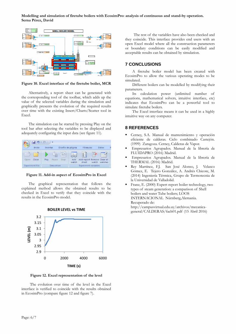
Figure 10. Excel interface of the firetube boiler, MCR
Alternatively, a report sheet can be generated with the corresponding tool of the toolbar, which adds up the value of the selected variables during the simulation and graphically presents the evolution of the required results over time with the existing Insert/Charts/Scatter tool in Excel.
The simulation can be started by pressing Play on the
tool bar after selecting the variables to be displayed and adequately configuring the input data (see figure 11).
Figure 11. Add-in aspect of EcosimPro in Excel The graphical representation that follows the
explained method allows the obtained results to be checked in Excel to verify that they coincide with the results in the EcosimPro model.
Figure 12. Excel representation of the level The evolution over time of the level in the Excel
interface is verified to coincide with the results obtained in EcosimPro (compare figure 12 and figure 7).
The rest of the variables have also been checked and
they coincide. This interface provides end users with an open Excel model where all the construction parameters or boundary conditions can be easily modified and acceptable results can be obtained by simulation.
7 CONCLUSIONS
A firetube boiler model has been created with EcosimPro to allow the various operating modes to be simulated.
Different boilers can be modelled by modifying their parameters.
Its calculation power (unlimited number of equations, mathematical solvers, intuitive interface, etc) indicates that EcosimPro can be a powerful tool to simulate firetube boilers.
The Excel interface means it can be used in a highly intuitive way on any computer.
8 REFERENCES
Cerney, S.A. Manual de mantenimiento y operación eficiente de calderas. Ciclo combinado Castejón. (1999) Zaragoza. Cerney, Calderas de Vapor.
Empresarios Agrupados. Manual de la librería de FLUIDAPRO (2016) Madrid.
Empresarios Agrupados. Manual de la librería de THERMAL (2016) Madrid.
Rey Martínez, F.J. San José Alonso, J. Velasco Gómez, E. Tejero González, A. Andrés Chicote, M. (2014) Ingeniería Térmica, Grupo de Termotecnia de la Universidad de Valladolid.
Franz, E. (2000) Expert report boiler technology, two types of steam generation: a comparison of Shell boilers and water Tube boilers; LOOS INTERNACIONAL Nürnberg,Alemania. Recuperado de: http://campusvirtual.edu.uy/archivos/mecanica-general/CALDERAS/fach01.pdf (15 Abril 2016)
2.9
2.95
3
3.05
3.1
3.15
3.2
0 2000 4000 6000
LEV
EL (
m)
TIME (s)
BOILER LEVEL vs TIME
Page: 7/7
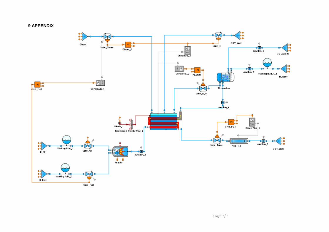
9 APPENDIX