Embed Size (px)
Citation preview


1
© 2009 EA Internacional
EcosimPro- 1 -ENTORNO DE SIMULACIÓN EcosimPro
1st Conference on Power Plant Simulation using EcosimPro
PRESENTATIONS IN THIS DOCUMENT
EcosimPro Simulation EnvironmentPedro Cobas, Empresarios Agrupados AIE
THERMAL_BALANCE libraryEusebio Huélamo, Empresarios Agrupados AIE
PIPELIQTRAN libraryEusebio Huélamo, Empresarios Agrupados AIE
Heat Balance of a Thermoelectric Solar Power PlantAlfonso Junquera, Empresarios Agrupados AIE
Heat Sink StudyEusebio Huélamo, Empresarios Agrupados AIE
Almaraz Nuclear Power Plant Steam Generator Level Control StudyEusebio Huélamo, Empresarios Agrupados AIE
Calculation of the Hydraulic Transients of the Circulating Water System(Montoir de Bretagne, France - CCGT 435 MW)
Laura Arenas, Empresarios Agrupados AIETransients in the Combined Cycle Natural Gas Supply System
Alfonso Junquera, Empresarios Agrupados AIEDesigning ITER Tritium Plants with EcosimPro
Carlos Moreno, CIEMAT - ITER
© 2009 EA Internacional
EcosimPro- 2 -ENTORNO DE SIMULACIÓN EcosimPro
1st Conference on Power Plant Simulation using EcosimPro
CONTACT
web: http://www.ecosimpro.comtelephone: 34 – 91 444 1539email: [email protected]

1
© 2009 EA Internacional
EcosimPro- 1 -ENTORNO DE SIMULACIÓN EcosimPro
Empresarios Agrupados Internacional (EAI)
Pedro CobasResponsible for the EcosimPro Development Team26th November 2009
Telephone: 34 – 91 446 9326E-mail: [email protected]: www.ecosimpro.com
SIMULATION ENVIRONMENT SIMULATION ENVIRONMENT EcosimProEcosimPro
1st Day of Energy Simulation Applications using EcosimPro
© 2009 EA Internacional
EcosimPro- 2 -ENTORNO DE SIMULACIÓN EcosimPro
What is EcosimPro?
EcosimPro is a state of the art modelling and simulation tool developed at EA over the last 19 years.
EcosimPro uses cutting-edge technology for acausal modelling of systems that can be depicted by differential algebraic equations and
discreet events.
EcosimPro has a human-machine interface that makes it easy to create models intuitively.
It was originally developed for the European Space Agency to simulate environmental control and life support systems (ECLSS) in the
International Space Station.
Today, it is ESA's standard modelling tool for ECLSS, Propulsion(satellites and rockets) and biological systems for long-term missions.

2
© 2009 EA Internacional
EcosimPro- 3 -ENTORNO DE SIMULACIÓN EcosimPro
What is EcosimPro?
EcosimPro can be used to simulate any 1D EcosimPro can be used to simulate any 1D phenomenon that can be portrayed by differential phenomenon that can be portrayed by differential algebraic equations, such as:algebraic equations, such as:
••Fluids in piping networksFluids in piping networks••Heat transferHeat transfer••Chemical reactionsChemical reactions••Control systemsControl systems••Electric circuitsElectric circuits••Aeronautical or space propulsion systemsAeronautical or space propulsion systems••Biological systemsBiological systems••Economic modelsEconomic models••Process plantsProcess plants••Mass and energy balancesMass and energy balances••Mechanical systemsMechanical systems••etc.etc.
© 2009 EA Internacional
EcosimPro- 4 -ENTORNO DE SIMULACIÓN EcosimPro
EcosimPro Users
International businesses and organizations:ESA, NASA, Canadian Space Agency, EADS Astrium, Thales Alenia,
Snecma, Swedish Space Agency, ITP, Teuchos, NTE, ASML, VOLVO, STORK, ALENIA, AVIO, CASA, etc.
Universities:Valladolid, Córdoba, Esc. Ingenieros Sevilla, Autónoma de Barcelona,
Girona, Leon, Cantabria, Las Palmas, UNED, Cadiz, Complutense, Politécnica de Madrid, Almeria, Lovaina, Stuttgart, Eindhoven, Liege,
Beijing, Athens, Cranfield, etc.
Technological centres:INTA, NLR, CERN, CTA(Tecnología Azucarera), Von Karman Institute,
CENER, CIEMAT, CSIC, etc.

3
© 2009 EA Internacional
EcosimPro- 5 -ENTORNO DE SIMULACIÓN EcosimPro
OverviewM
odel
ling
Mod
elli
ng
••Applicable to 0D and 1D modelling problems Applicable to 0D and 1D modelling problems ••DifferentialDifferential--algebraic equationsalgebraic equations••EasyEasy--toto--learn acausallearn acausal--objectobject--oriented modelling language oriented modelling language ••GraphicsGraphics--based tool for creating components "by drawing"based tool for creating components "by drawing"••Math wizards for generating robust final modelsMath wizards for generating robust final models
Inte
rfac
eIn
terf
ace
Cor
eC
ore
••Calls to external functions C, C++ and Fortran Calls to external functions C, C++ and Fortran ••Automatic generation of DLLs and C++ to reAutomatic generation of DLLs and C++ to re--use modelsuse models••AddAdd--in to execute the models from Excelin to execute the models from Excel••Module to execute the models from MatlabModule to execute the models from Matlab
••Equation solvers thoroughly tested on complex problemsEquation solvers thoroughly tested on complex problems••Symbolic and numerical handling of equationsSymbolic and numerical handling of equations••Calculation of steady states and transientsCalculation of steady states and transients••Complete debugging information in HTMLComplete debugging information in HTML
© 2009 EA Internacional
EcosimPro- 6 -ENTORNO DE SIMULACIÓN EcosimPro
Graphic Modelling Environment

4
© 2009 EA Internacional
EcosimPro- 7 -ENTORNO DE SIMULACIÓN EcosimPro
Interactive Simulation Environment
© 2009 EA Internacional
EcosimPro- 8 -ENTORNO DE SIMULACIÓN EcosimPro
Basic Library Development Environment

5
© 2009 EA Internacional
EcosimPro- 9 -ENTORNO DE SIMULACIÓN EcosimPro
With With acausalacausal modellingmodelling, equations can be entered not as , equations can be entered not as assignations but as physical equivalencies. assignations but as physical equivalencies.
For example, you can write:For example, you can write:
Modelling of Components
EcosimProEcosimPro lets you model components in two different ways:lets you model components in two different ways:-- By reBy re--using already made components by aggregation and using already made components by aggregation and
inheritanceinheritance-- Create new components from their Create new components from their modellingmodelling equations or equations or
experimental data.experimental data.
F = m * aF = m * aoo
F F –– m * a = 0m * a = 0oo
a= F/ma= F/m
This is key to reusing the same components for different studies, because:
the equations are changed automatically!
© 2009 EA Internacional
EcosimPro- 10 -ENTORNO DE SIMULACIÓN EcosimPro
0,,
t
dtxd
xf
0,,
dtxd
txftxfdtxd
0,0,0,
txftxf
Individual cases:Individual cases:
Mathematical algorithms
DAEsDAEs
ODEs
Algebraic
Equations
EcosimPro has powerful differential algebraic equation (DAE) EcosimPro has powerful differential algebraic equation (DAE) solvers.solvers.

6
© 2009 EA Internacional
EcosimPro- 11 -ENTORNO DE SIMULACIÓN EcosimPro
Interfaces with external programs
Functions in CFunctions in C
ExcelExcel
Functions in FORTRANFunctions in FORTRAN
Classes in C++Classes in C++
ActiveXActiveX
MATLAB / SimulinkMATLAB / Simulink
EcosimProEcosimPro
© 2009 EA Internacional
EcosimPro- 12 -ENTORNO DE SIMULACIÓN EcosimPro
Four types of users
LEVEL 1 : Library LEVEL 1 : Library modellersmodellers; they need thorough knowledge ; they need thorough knowledge of the math of the components and the of the math of the components and the modellingmodelling languagelanguage
LEVEL 2 : Users of finished libraries. They graphically design LEVEL 2 : Users of finished libraries. They graphically design systems.systems.
LEVEL 3: They create multiple experiments on a closed LEVEL 3: They create multiple experiments on a closed mathematical model. Transient, steadymathematical model. Transient, steady--state studies, state studies, optimizations, etc.optimizations, etc.
LEVEL 4 : They use LEVEL 4 : They use EcosimProEcosimPro models in Excel, models in Excel, MatlabMatlab, C++, , C++, Visual Basic, etc. They do not need to have Visual Basic, etc. They do not need to have EcosimProEcosimProinstalled on their PC.installed on their PC.

7
© 2009 EA Internacional
EcosimPro- 13 -ENTORNO DE SIMULACIÓN EcosimPro
••What is a port?What is a port?
••The components are connected by means of ports (electric, The components are connected by means of ports (electric, control fluid, heat, etc.).control fluid, heat, etc.).
••This greatly facilitates the modelling of complex systems, This greatly facilitates the modelling of complex systems, since it does not require working at the level of variables. since it does not require working at the level of variables.
••A port encapsulates a set of variables that are interchanged A port encapsulates a set of variables that are interchanged togethertogether
••The component is the most elementary building block in EcosimProThe component is the most elementary building block in EcosimPro..••It is the equivalent concept to class in programming.It is the equivalent concept to class in programming.••The difference is that instead of encapsulating methods or functThe difference is that instead of encapsulating methods or functions, ions, it encapsulates a mathematical model. it encapsulates a mathematical model.
Components and Ports
••What is a component?What is a component?
© 2009 EA Internacional
EcosimPro- 14 -ENTORNO DE SIMULACIÓN EcosimPro
••Components are defined by:Components are defined by:
••The declaration of data and variables The declaration of data and variables (valve area, pressure difference,(valve area, pressure difference,…….).)
P
CvQ
••The equations that portray behaviourThe equations that portray behaviour
••Input/Output ports Input/Output ports
Components and Ports
Valve Component

8
© 2009 EA Internacional
EcosimPro- 15 -ENTORNO DE SIMULACIÓN EcosimPro
PORT FluidSUM REAL w "mass flow (kg/s)"EQUAL REAL p "pressure (Pa)"
END PORT
PORT Signal SINGLE IN "Analog signals 1D port"EQUAL OUT REAL signal "Analog signal values (-)"
END PORT
Components and Ports
Fluid Port interchanges:-mass flow- pressure
Signal Port interchanges:-Analog signal
© 2009 EA Internacional
EcosimPro- 16 -ENTORNO DE SIMULACIÓN EcosimPro
COMPONENT ValvePORTS
IN Fluid f_in -- Fluid port inputOUT Fluid f_out -- Fluid port outputIN Signal position -- Control port input
DATAREAL Cv -- Maximum flow area
DECLSREAL dP -- Difference in pressureREAL m -- Mass flow
CONTINUOUSf_in.P - f_out.P = dP -- differential pressure calculationm / sqrt(dP * f_in.rho) = Cv * position.signalf_in.m = mf_in.m = f_out.m
END COMPONENT
Components and Ports
Mathematical Mathematical model of the model of the
valvevalve
The equations can be written in any order and format. EcosimPro then converts
them into symbols

9
© 2009 EA Internacional
EcosimPro- 17 -ENTORNO DE SIMULACIÓN EcosimPro
Components and Ports
x
y
T
y
L
222
´´
´´
Lyx
L
yTgmym
L
xTxm
••EcosimPro lets you intuitively model the EcosimPro lets you intuitively model the equations in derivativesequations in derivatives
••Dynamic model of a pendulumDynamic model of a pendulum
© 2009 EA Internacional
EcosimPro- 18 -ENTORNO DE SIMULACIÓN EcosimPro
Components and Ports
•• Dynamic model of a pendulumDynamic model of a pendulumCOMPONENT pendulum "Pendulum example"
DATA
REAL g = 9.806 UNITS “m/s**2“ “Gravity"REAL L = 1. UNITS “m“ "Pendulum length"REAL m = 1. UNITS “kg” "Pendulum mass"
DECLS
REAL x UNITS “m“ "Pendulum X position"REAL y UNITS “m“ "Pendulum Y position"REAL T UNITS “m“ "Pendulum wire tension force"
CONTINUOUS
m * x'' = - T * (x / L)
m * y'' = M * g - T * (y / L)
x**2 + y**2 = L**2
END COMPONENT
222
´´
´´
Lyx
L
yTgmym
L
xTxm

10
© 2009 EA Internacional
EcosimPro- 19 -ENTORNO DE SIMULACIÓN EcosimPro
Pipe1
Pipe2
Pipe3
Pipe4
Pipe6
Pipe5
Pipe7
Pipe object
Connection between
components
Modelling the Hydraulic System
• Example of complete modelling and simulation of the hydraulic system based on a single Pipe component.
© 2009 EA Internacional
EcosimPro- 20 -ENTORNO DE SIMULACIÓN EcosimPro
• Step 1: Define a fluid port that exchanges mass flow and pressure
PORT Fluid
SUM REAL w "mass flow (kg/s)"EQUAL REAL p "pressure (Pa)"
END PORT
Variables that are exchanged in each
connection
Modelling the Hydraulic System

11
© 2009 EA Internacional
EcosimPro- 21 -ENTORNO DE SIMULACIÓN EcosimPro
• Step 2: An abstract basic parent component is modelled(one that can not be instantiated)
ABSTRACT COMPONENT Channel
PORTSIN Fluid hp_in "hydraulic port inlet" OUT Fluid hp_out "hydraulic port outlet"
DATAREAL z_in = 0. "geometric elevation of inlet (m)"REAL z_out = 0. "geometric elevation of outlet (m)"
TOPOLOGYPATH hp_in TO hp_out
END COMPONENT
Define two connection ports
Declare any common data
Modelling the Hydraulic System
© 2009 EA Internacional
EcosimPro- 22 -ENTORNO DE SIMULACIÓN EcosimPro
• Step 3: The Pipe component is modelled
COMPONENT Pipe IS_A ChannelDATA
REAL f = 0.020 "friction factor ()"REAL l = 1. "pipe length (m)"REAL d = 0.1 "pipe diameter (m)"REAL dp_lam = 1000. "pressure drop for laminar flow (Pa)"
DECLSREAL A "area (m**2)"REAL w_lam "mass flow corresponding to dp_lam (kg/s)“
CONTINUOUS-- Geometry
A = 0.25 * PI * d**2
-- Laminar flow conditionw_lam / A = sqrt(2 * d * dp_lam * rho / f / l)
-- Conservation of masshp_out.w = hp_in.w
-- Conservation of momentumhp_in.p - hp_out.p + rho * g * ( z_in - z_out ) = \
0.5 * f * l * fpow2(hp_in.w, w_lam) / d / rho / A**2END COMPONENT
Declare the data
Write the equations
Declare the variables
CAREFUL! These are equations,
NOT ASSIGNATIONS
Modelling the Hydraulic System
Inheriting from the Channel

12
© 2009 EA Internacional
EcosimPro- 23 -ENTORNO DE SIMULACIÓN EcosimPro
• Step 4: Write the code in EcosimPro and compile
Modelling the Hydraulic System
Encode the piping model and
compile
© 2009 EA Internacional
EcosimPro- 24 -ENTORNO DE SIMULACIÓN EcosimPro
• Step 5: Create an icon for the component
Draw an icon for the piping
Modelling the Hydraulic System
It now appears on the palette

13
© 2009 EA Internacional
EcosimPro- 25 -ENTORNO DE SIMULACIÓN EcosimPro
• Step 6: Design the piping network (which will be another component).
Palette
Modelling the Hydraulic System
Create the schematic of the hydraulic network
and compile
© 2009 EA Internacional
EcosimPro- 26 -ENTORNO DE SIMULACIÓN EcosimPro
Step 7: Create a valid mathematical partitionStep 7: Create a valid mathematical partition
Modelling the Hydraulic System
•• EcosimPro has wizards to help the user define EcosimPro has wizards to help the user define robust final mathematical models. They are in charge of makingrobust final mathematical models. They are in charge of makinga dialog with the user to define:a dialog with the user to define:
•• Variables boundariesVariables boundaries••Break algebraic linksBreak algebraic links••Reduce high index mathematical problemsReduce high index mathematical problems
Wizard to define boundary conditions

14
© 2009 EA Internacional
EcosimPro- 27 -ENTORNO DE SIMULACIÓN EcosimPro
Step 8: Create an experiment that integrates 15 Step 8: Create an experiment that integrates 15 seconds of the model imposing a set of laws on seconds of the model imposing a set of laws on boundary conditions.boundary conditions.
Define values for boundary conditions
Integrate the model 15 seconds
Modelling the Hydraulic System
© 2009 EA Internacional
EcosimPro- 28 -ENTORNO DE SIMULACIÓN EcosimPro
• Step 9: Run the simulation
Modelling the Hydraulic System
See the evolution of any variable in
the model

15
© 2009 EA Internacional
EcosimPro- 29 -ENTORNO DE SIMULACIÓN EcosimPro
CURRENT AREAS OF SIMULATIONCURRENT AREAS OF SIMULATION
© 2009 EA Internacional
EcosimPro- 30 -ENTORNO DE SIMULACIÓN EcosimPro
Current Libraries (I)
Thermal balances in Thermal balances in power plants power plants
(nuclear, combined cycle, etc.)(nuclear, combined cycle, etc.)
THERMAL BALANCETHERMAL BALANCE
Flow of compressible fluidsFlow of compressible fluidsin piping networksin piping networks
FLUIDFLUID
Systems for environmental control Systems for environmental control and life support in manned spacecraftand life support in manned spacecraft
ECLSSECLSS
Hydraulic transients Hydraulic transients in space propulsionin space propulsion
PROPSATPROPSAT
Hydraulic Hydraulic transients transients
PIPELIQTRANPIPELIQTRAN
Hydraulic networksHydraulic networksSteady stateSteady state
PIPELIQPIPELIQ
Control systemsControl systemsSelfSelf--regulationregulation
CONTROLCONTROL
Thermal Analysis Thermal Analysis of Satellitesof Satellites
THERMALTHERMAL EcosimProEcosimPro

16
© 2009 EA Internacional
EcosimPro- 31 -ENTORNO DE SIMULACIÓN EcosimPro
Current Libraries (II)
Aeronautic propulsionAeronautic propulsion
TURBOTURBO
Electric circuitsElectric circuits
ELECTRICELECTRIC
Mechanical systemsMechanical systems1D1D
MECHANICALMECHANICAL
Predictive controlPredictive controlPREDICTPREDICT
Process PlantsProcess Plants
PROCESSPROCESS
FlightFlightmechanicsmechanics
FLIGHTFLIGHT
Rocket and satelliteRocket and satellitePropulsionPropulsionESPSSESPSS EcosimProEcosimPro
Loop Heat PipesLoop Heat PipesHEATPIPEHEATPIPE
© 2009 EA Internacional
EcosimPro- 32 -ENTORNO DE SIMULACIÓN EcosimPro
CONTROL library
Library with the standard control components such as P Library with the standard control components such as P controllers, PI & PIDs, signal generators, logic gates, controllers, PI & PIDs, signal generators, logic gates, integrators, transfer functions, etc.integrators, transfer functions, etc.

17
© 2009 EA Internacional
EcosimPro- 33 -ENTORNO DE SIMULACIÓN EcosimPro
CONTROL library
Example of two water tanks connected by a pipe with a valve Example of two water tanks connected by a pipe with a valve to regulate the flow, a flowmeter and PID controllerto regulate the flow, a flowmeter and PID controller
© 2009 EA Internacional
EcosimPro- 34 -ENTORNO DE SIMULACIÓN EcosimPro
MECHANICAL Library
Library of 1D traversing mechanical components and Library of 1D traversing mechanical components and rotational mechanical systems such as masses, force rotational mechanical systems such as masses, force and momentum generators, springs, actuators, sensors, and momentum generators, springs, actuators, sensors, pistons, levers, brakes, etc.pistons, levers, brakes, etc.

18
© 2009 EA Internacional
EcosimPro- 35 -ENTORNO DE SIMULACIÓN EcosimPro
MECHANICAL Library
Example: A transmission system with 3 masses: Example: A transmission system with 3 masses: brake, clutch, and a spring with a shock absorber brake, clutch, and a spring with a shock absorber
© 2009 EA Internacional
EcosimPro- 36 -ENTORNO DE SIMULACIÓN EcosimPro
ELECTRICAL library
Library of electrical and electronic components such as Library of electrical and electronic components such as signal generators, capacitors, inductors, diodes, signal generators, capacitors, inductors, diodes, transistors, etc.transistors, etc.

19
© 2009 EA Internacional
EcosimPro- 37 -ENTORNO DE SIMULACIÓN EcosimPro
ELECTRICAL library
Example: a motor powered by power stages Example: a motor powered by power stages and a mechanical unit connected to the drive shaft and a mechanical unit connected to the drive shaft
© 2009 EA Internacional
EcosimPro- 38 -ENTORNO DE SIMULACIÓN EcosimPro
FLUIDAPRO library
Library for Library for modellingmodelling the dynamics of systems of fluids (gas, liquid, or the dynamics of systems of fluids (gas, liquid, or two phase), reverse flow, inertia, heat transfer, pneumatic and two phase), reverse flow, inertia, heat transfer, pneumatic and hydraulic actuators, heat exchangers, etc.hydraulic actuators, heat exchangers, etc.
Volume1
WorkingFluid
ValvePressRegDown ValvePressRegUp
ValveCheck ValveCheck_Dynamic Valve
2
1 3
Tee
Tube
Jun_TMD Junction
Pipe
Piston
Piston_a
Pump
Pump_vacuum Filter
DeadEnd
Actuator_1C
ChamberActuator_2C
Actuator_A2C
TO
AbstracJunctionFLUIDAPRO
21
Volume2
AbstracJunctionLoss
VolumenConstant ChannelVolumenVariable
Ev_4wEv_3wVolPT_TMD VolPx_TMD VolTx_TMD
TIME dependent Volumes
Jun
SensorJun
Pipe
SensorPipe
Vol
SensorVol
Volume8
Tube_Annular

20
© 2009 EA Internacional
EcosimPro- 39 -ENTORNO DE SIMULACIÓN EcosimPro
PipeLiqTran Library
Example: Modelling a vacuum network
HP_tank
V1
1
2
3
4
Tank1
V2Ambient2
R2
R3
Ambient1
Pump_exitPump
21 3
Col2Filter
Junction_6
Junction_7
Junction_8
Junction_11
Junction_13
Regulator
2
1 3
Col1P_12
P_15
P_14
P_25
P_28
P_24
P_26
P_42
WorkingFluid_1
2
13
Col3
1
2
3
Tank2
© 2009 EA Internacional
EcosimPro- 40 -ENTORNO DE SIMULACIÓN EcosimPro
ECLSS Library
• ECLSS (Environmental Control and Life Support System) is a standard ESA library for modelling ECLSS in manned spacecraft.
• It has been extensively used to model various COLUMBUS subsystems.• Its components include cockpit, pumps, crew physiological model,
chemical reactors, etc.

21
© 2009 EA Internacional
EcosimPro- 41 -ENTORNO DE SIMULACIÓN EcosimPro
ECLSS Library
Modelling the Columbus Modelling the Columbus Air Control System:Air Control System:
© 2009 EA Internacional
EcosimPro- 42 -ENTORNO DE SIMULACIÓN EcosimPro
ESPSS Library
ESPSS (European Space Propulsion System Simulation) is a set of ESPSS (European Space Propulsion System Simulation) is a set of libraries libraries for modelling and simulating propulsion systems for satellites afor modelling and simulating propulsion systems for satellites and nd rockets.rockets.
ESPSS belongs to the ESA and is their standard modelling tool.ESPSS belongs to the ESA and is their standard modelling tool.
It includes the following libraries:It includes the following libraries:
•• Fluids (one and two phases)Fluids (one and two phases)
•• Thermodynamic propertiesThermodynamic properties
•• Combustion chambers Combustion chambers
and nozzlesand nozzles
•• TanksTanks
•• Turbine machineryTurbine machinery

22
© 2009 EA Internacional
EcosimPro- 43 -ENTORNO DE SIMULACIÓN EcosimPro
ESPSS Library
Model of a multiModel of a multi--stage rocket engine modelstage rocket engine model
© 2009 EA Internacional
EcosimPro- 44 -ENTORNO DE SIMULACIÓN EcosimPro
PROCESS Library
LT
TT PT
Boiler
LT
TT PT
AT
Boiler_complete
AT
FCFT
FCFT
FT
FC
LT
FCFT
FC
FTLT
FT TT
PT
PC
TT
AT element 1(n)
(n)
ATelement 2(n)
Column
ATTT
TT AT
TT AT
Column_simple
PT PDTFT
Compressor
v ariablesmanipulated
controlledv ariables
disturbance
setpoints
v ariables
manipulatedvariables
DMCmeasured
DMC
dryer
AT
Dryer
AT
AT
Dryer_complete
LT
PT
AT
PT
Evaporator
PT
LT
TTAT
ATAT
Flash
FT
FC
Flow_gas
FT
FC
Flow_liquid
FT
FC
Flow_steam
AT TT
Furnace
v ariablesmanipulated GPC
controlledv ariables
disturbance
setpoints
v ariables
manipulatedvariablesmeasured
GPC
TT TT
TT TT
Heat_Exchanger_gas_gas
TT TT
TT TT
Heat_Exchanger_liq_gas
TT TT
TT TT
Heat_Exchanger_liq_liq
TT TT
TT TT
Heat_Exchanger_liq_steam
mix
Mix_gas
mix
Mix_liquid
mux
Mux
WT FT AT
Pipe_gas
FTWT AT
Pipe_liquid
FTWT
Pipe_steam
PTPDT
FT
Pump_liquid
outflow
AT
TT
LT
DT
CSTR
Reactor
AT
TT
LT
DT
batch reactor
Reactor_batch
PT TT
AT
gas reactor
Reactor_gas
CSTR
outflow
AT
TT
DTiquid jacket
TTTT
LT
Reactor_jacket_liquid
CSTR
outflowTT
steam jacketTT
TT
ATDT
LT
Reactor_jacket_steam
Sink_gasSink_liquid Sink_steam
Source_constant
Source_gas
Source_liquid
Source_steam
AT
TT
DT
LT
AT
outf low
CSTR
Tank
PT TT
AT
gas tank
AT
Tank_gas
AT
TT
DT
LT
AT
AT
ATPT
pressured tank
Tank_pressured
P = f(F)union
Union_gas
P = f(F)union
Union_liquid
FTWT (%)
Valve_gas
FTWT(%)
Valve_liquid
FTWT (%)
Valve_steam
The PROCESS library has the typical components for modelling indThe PROCESS library has the typical components for modelling industrial ustrial processes.processes.
It has components such as boilers, distillation columns, reactorIt has components such as boilers, distillation columns, reactors, heat s, heat exchangers, etc.exchangers, etc.

23
© 2009 EA Internacional
EcosimPro- 45 -ENTORNO DE SIMULACIÓN EcosimPro
PROCESS Library
Model of a steam boiler Model of a steam boiler with a control systemwith a control system
AT
TT
DT
LT
AT
outflow
CSTR
tank_1
Source_liquid_1TT TT
TT TT
heater
FTWT(%)
valve_1
PI
sv
Cntrl_PI_1
Sink_liquid_1
Source_gas_1
Source_gas_2
Gain_1
Source_liquid_2
PI
s v
Cntrl_PI_3PI
sv
Cntrl_PI_2FT
FC
Flow_liquid_1
FT
FC
Flow_steam_1
FT
FC
Flow_gas_1
LT
TT PT
AT
boilerFT
FC
Flow_gas_2
AT
TT
DT
LT
AT
outflow
CSTR
tank_2
FTWT(%)
valve_2
PI
sv
Cntrl_PI_4
PI
s v
Cntrl_PI_5
© 2009 EA Internacional
EcosimPro- 46 -ENTORNO DE SIMULACIÓN EcosimPro
TURBO Library
A complete library for modelling aeronautical gas turbines with A complete library for modelling aeronautical gas turbines with components such as compressors, turbines, combustion chambers, components such as compressors, turbines, combustion chambers, heat exchangers, shafts, etc.heat exchangers, shafts, etc.

24
© 2009 EA Internacional
EcosimPro- 47 -ENTORNO DE SIMULACIÓN EcosimPro
TURBO Library
Example: Modelling a twinExample: Modelling a twin--shaft turbofan engineshaft turbofan engine

1
© 2009 EA Internacional
EcosimPro- 1 -Librería Thermal Balance
Empresarios Agrupados Internacional (EAI)
Eusebio Huélamo 26th November 2009
Telephone: 34 – 91 448 85 98 http: www.ecosimpro.com
THERMAL BALANCE LIBRARYTHERMAL BALANCE LIBRARY
1st Day of Energy Simulation Applications using EcosimPro
© 2009 EA Internacional
EcosimPro- 2 -Librería Thermal Balance
Originally the intention was to unify different known thermal balance programs in a generic EcosimPro library called THERMAL_BALANCE. The programs were:
Thermal Balance calculation program HBAL
Thermal Balance calculation program ANTEO
The formulation of the old programs was adapted to acausal modelling and based on components of EcosimPro.
A much easier interface was attained, both for data entry and for inicialization of variables and resolution of the model generated.
THERMAL_BALANCE has the ability to expand the library with new static or dynamic components.
Origin of the library

2
© 2009 EA Internacional
EcosimPro- 3 -Librería Thermal Balance
The THERMAL_BALANCE library is used for stationary thermal balance studies in typical power plants (water-steam, co-generation, etc).
The library contains a wide range of pre-modelled components that cover all modelling requirements for these types of systems, such as: pumps, compressors, valves, pipes, motors, heat exchangers, condensers, turbines, evaporators, electric generators, cooling towers, etc.
Apart from water, the library can work with air, oxygen, carbon dioxide, cabon monoxide, helium, argon, methane, propane, butane, and sulphur dioxide. The user can easily add new fluids.
The diagrams of the models created are similar to the plant diagrams, which makes it easy to identify any part of the model.
Description of the library
© 2009 EA Internacional
EcosimPro- 4 -Librería Thermal Balance
Toolkit of the library

3
© 2009 EA Internacional
EcosimPro- 5 -Librería Thermal Balance
SOME EXAMPLES
Examples
© 2009 EA Internacional
EcosimPro- 6 -Librería Thermal Balance
Power Plant Example modelled using Thermal_Balance
Example ofmodel Extraction to heater
Example of modelling cycles

4
© 2009 EA Internacional
EcosimPro- 7 -Librería Thermal Balance
Modelling of Fuel Treatment Pool
© 2009 EA Internacional
EcosimPro- 8 -Librería Thermal Balance
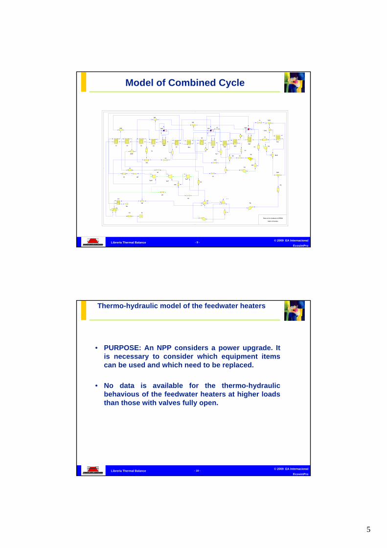
Model of Combined Cycle
5
© 2009 EA Internacional
EcosimPro- 9 -Librería Thermal Balance
ECO
ECO
ECO
SHSH
V1
V2
S8
Eco4 Eco3 Eco2
Eco1
EvLP
EvIPEvHP
P1
SH
S3
V3
SH
SH
P3
mix3
mix1
P2
A
G
TurLP
mix4
P8
P7
P6
P5 Air
Gas
TurIPTurHP
Pu1
Div5Pu2
Pu3
V5
Tg
Con
DrHP DrLPDrIP
ECO
SH
Mix21
Mix22
Pu5
Div31
Div41
Planta de Ciclo Combinado de CASTEJON
Modelo de Ecosimpro
ECO
VHP
VIP
VLP
VATH
S1 S6 S5
RHATT
S4
M10
FH
M11
ALT
V4
M12
N
circ_in circ_out
aire_in
aire_out
Div7 V6
P4
dg_2
Model of Combined Cycle
© 2009 EA Internacional
EcosimPro- 10 -Librería Thermal Balance
• PURPOSE: An NPP considers a power upgrade. It is necessary to consider which equipment items can be used and which need to be replaced.
• No data is available for the thermo-hydraulic behavious of the feedwater heaters at higher loads than those with valves fully open.
Thermo-hydraulic model of the feedwater heaters

6
© 2009 EA Internacional
EcosimPro- 11 -Librería Thermal Balance
• The manufacturers, in accordance with the regulations of the Heat Exchange Institute, in order to facilitate the behavioural calculations, provide Terminal Temperature Difference (TTD) curves and Drains Cooler Approach (DCA) depending on the flow of condensate.
The question is:
• Can the original curves from the suppluier be used, with a simple extrapolation?
Thermo-hydraulic model of the feedwater heaters
© 2009 EA Internacional
EcosimPro- 12 -Librería Thermal Balance
Thermo-hydraulic model of the feedwater heaters

7
© 2009 EA Internacional
EcosimPro- 13 -Librería Thermal Balance
Thermo-hydraulic model of the feedwater heaters
© 2009 EA Internacional
EcosimPro- 14 -Librería Thermal Balance
Thermo-hydraulic model of the feedwater heaters

8
© 2009 EA Internacional
EcosimPro- 15 -Librería Thermal Balance
Thermo-hydraulic model of the feedwater heaters
© 2009 EA Internacional
EcosimPro- 16 -Librería Thermal Balance
Thermo-hydraulic model of the feedwater heaters

9
© 2009 EA Internacional
EcosimPro- 17 -Librería Thermal Balance
Thermo-hydraulic model of the feedwater heaters
© 2009 EA Internacional
EcosimPro- 18 -Librería Thermal Balance
Thermo-hydraulic model of the feedwater heaters

10
© 2009 EA Internacional
EcosimPro- 19 -Librería Thermal Balance
Thermo-hydraulic model of the feedwater heaters
© 2009 EA Internacional
EcosimPro- 20 -Librería Thermal Balance
• Using EcosimPro and the THERMAL-BALANCE library some validated models were obtained, which simulate quite accurately the thermo-dynamic behaviour of the feedwater heaters.
• It is possible to obtain from these models, values of TTD and DCA for greater loads and different layouts then the originally planned ones, and can be used for other calculations with the same program or with other thermal balance programs.
• These models can be used to check the effect of pipe blockages on the TTD and DCA curves of the heaters.
Thermo-hydraulic model of the feedwater heaters

11
© 2009 EA Internacional
EcosimPro- 21 -Librería Thermal Balance
Solar Plant Model with accumulators
© 2009 EA Internacional
EcosimPro- 22 -Librería Thermal Balance
Solar Plant Model with accumulators
– Model of operation of solar plant with direct supply to the cycle and charging of the accumulators.
– The cycle is maintained at 100% power, charging the accumulators with the excess energy supplied.
– When the first accumulator is fully charged, the excess flow is derived to the second accumulator, and so on until all are full. The accumulators are discharged in the same way, ie sequentially.
– The following graphs show, for the filling sequence, the evolution of the energy transmitted by the receptor, the flow entering the accumulators, the pressures, and the levels.

12
© 2009 EA Internacional
EcosimPro- 23 -Librería Thermal Balance
Solar Plant Model with accumulators
© 2009 EA Internacional
EcosimPro- 24 -Librería Thermal Balance
Conclusions
EcosimPro's THERMAL_BALANCE library is a very powerful tool for modelling conventional thermal cycle systems in fossil-fired, nuclear, co-generation, combined cycle or any other kind of power plant.

1
© 2009 EA Internacional
EcosimPro- 1 -PIPELIQTRAN Library
Empresarios Agrupados Internacional (EAI)
Eusebio Huélamo26 de November de 2009
Phone: 34 – 91 448 85 98 http: www.ecosimpro.com
PIPELIQTRAN LibraryPIPELIQTRAN Library
1ª Jornada de Aplicaciones de Simulación en Energía con EcosimPro
© 2009 EA Internacional
EcosimPro- 2 -PIPELIQTRAN Library
Overview of PIPELIQTRAN Library
Model Building Rules
Components of the PIPELIQTRAN Library
Examples
Conclusions
Index
2
© 2009 EA Internacional
EcosimPro- 3 -PIPELIQTRAN Library
Index
Overview of PIPELIQTRAN Library
Model Building Rules
Components of the PIPELIQTRAN Library
Examples
Conclusions
© 2009 EA Internacional
EcosimPro- 4 -PIPELIQTRAN Library
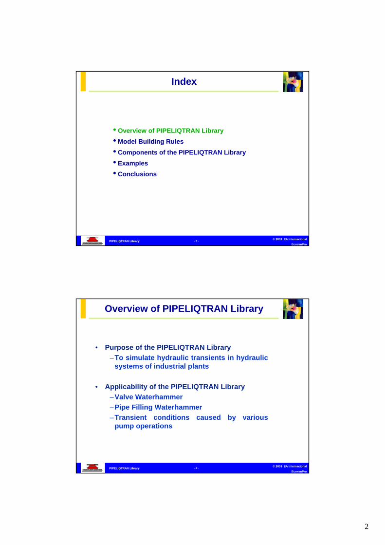
• Purpose of the PIPELIQTRAN Library
–To simulate hydraulic transients in hydraulic systems of industrial plants
• Applicability of the PIPELIQTRAN Library
–Valve Waterhammer
–Pipe Filling Waterhammer
–Transient conditions caused by various pump operations
Overview of PIPELIQTRAN Library

3
© 2009 EA Internacional
EcosimPro- 5 -PIPELIQTRAN Library
Phenomena and assumptions:
• Working fluid is a liquid• One-dimensional flow• Reverse flow• Constant composition of the fluid• Fluid properties depend on the temperature• Quasi-stationary loss pressures• Heat accumulation in the liquid and in the tube walls• Fluid dynamic pressure
Overview of PIPELIQTRAN Library
© 2009 EA Internacional
EcosimPro- 6 -PIPELIQTRAN Library
• Available working fluids:
– H2O Water
– UserDef1 User Defined Fluid Number 1
– UserDef2 User Defined Fluid Number 2
It is possible to define new working fluids
Overview of PIPELIQTRAN Library

4
© 2009 EA Internacional
EcosimPro- 7 -PIPELIQTRAN Library
Index
Overview of PIPELIQTRAN Library
Model Building Rules
Components of the PIPELIQTRAN Library
Examples
Conclusions
© 2009 EA Internacional
EcosimPro- 8 -PIPELIQTRAN Library
• Model Building Rules
– Two Types of Components: Pipes and Junctions
– Connections have to go from a Junction to a Pipe (it is not possible to connect 2 pipes, neither 2 junctions)
– Multiple connections are forbidden (a collector has to be use)
– The elevations and the crossed areas are defined in the pipes
Model Building Rules
5
© 2009 EA Internacional
EcosimPro- 9 -PIPELIQTRAN Library
• Model Building Advice
– It is advisable that all the ports are interconnected
– To generate a default partition
– To specify the working fluid in the body of the experiment
– To chose a right number of nodes for each pipe
– To specify a right communication interval
– To change the value of the absolute error (ABS_ERROR) to a smaller value in the body of the experiment if it is going to work with very small mass flows.
– It is considered direct flow from port f1 to port f2
Model Building Rules
© 2009 EA Internacional
EcosimPro- 10 -PIPELIQTRAN Library
• Definition of the working fluid
– The working fluid is a variable for all the components
– The current version of PIPELIQTRAN uses the same working fluid for a determinate circuit in the model because the type of fluid is a variable that is exchanged between the ports of the components.
– It is necessary to define the working fluid in the experiment, if not the first element of the fluid list is going to be used
– Working fluids can be changed in the experiments but this is not a recommended practice
Model Building Rules

6
© 2009 EA Internacional
EcosimPro- 11 -PIPELIQTRAN Library
Overview of PIPELIQTRAN Library
Model Building Rules
Components of the PIPELIQTRAN Library
Examples
Conclusions
Index
© 2009 EA Internacional
EcosimPro- 12 -PIPELIQTRAN Library
Classification of Components by Port Direction
• Pipe: Two fluid inlet ports (f1 y f2).
• Junctions: For non-pipe components all the fluid ports are outlets
1 2
Pt 1
2
3
4
1 2
1 21 2
Components of the PIPELIQTRAN Library

7
© 2009 EA Internacional
EcosimPro- 13 -PIPELIQTRAN Library
Ht m Ps Pt 1 2
1
2
3
1
2
3
4
1
23
45
1
2 34
567
F
1 2
1 2 1 2
P
1 2
1 2
1 2
1 2
1 2 1 2
1 2
1 2
Accumulator Bound Bound_Ht Bound_M Bound_Ps Bound_Pt CheckValve Col2
1
2 34
567
Col3 Col4 Col5 Col6 Col7 Engine ExitValve ExpanderASA
1 2
1 2
1 2
c1
c2
h1
h2
ExpanderConical ExpanderSudden Filter FlowMeter Grid Hex
T
1 2
Pipe PressLossPump
VacuumBreaker Tank1Pump_4q
WaterBox
Psensor Tsensor Valve ZeroLossJun ZeroLossPipe
1 2
Components of the PIPELIQTRAN Library
© 2009 EA Internacional
EcosimPro- 14 -PIPELIQTRAN Library
Component Pipe
• The pipe is the main component of the library
• It is the component used to interconnect components in the model
1 2
Components of the PIPELIQTRAN Library

8
© 2009 EA Internacional
EcosimPro- 15 -PIPELIQTRAN Library
Component Pipe
Phenomena modelled
• Number of variable nodes (Discretization)• Waterhammer waves• Equation of energy (optional: FALSE)• Cavitation in inner points (optional: TRUE)• Gas release (optional: FALSE)• Sound speed modified by wall extensibility and by gas release• Pressure losses calculated according to static friction factors• The elevations of the pipe stretches• Nominal diameters and Schedules• Number of parallel tubes
Components of the PIPELIQTRAN Library
© 2009 EA Internacional
EcosimPro- 16 -PIPELIQTRAN Library
Component Pipe
CV n-1 CV n CV n+1
Jun nJun Jun n+1
Conservation of Mass & Energy
They are applied to control volumes
)( 1
2
jjj
j mmVc
dt
dP
pj
jpjjpjj
cV
TcmTcm
dt
dT
)( 11
Components of the PIPELIQTRAN Library

9
© 2009 EA Internacional
EcosimPro- 17 -PIPELIQTRAN Library
Component Pipe
Sound speed• Effect of the pipe-wall elasticity
Three support situations for a thin-walled pipeline are examined and the wave speed formulas modified:
a) pipe anchored with expansion joints throughout
b) pipe anchored at its upstream end only
c) pipe anchored throughout against axial movement
11
'
cEK
cc o
eD
c in1
45
1 eD
c in
21 1
eD
c in
)a
)b
)c
Components of the PIPELIQTRAN Library
© 2009 EA Internacional
EcosimPro- 18 -PIPELIQTRAN Library
Component PipeSound speed
– Effects of Gas Release
Calculation of the rate of mass of gas release per unit of volume of liquid
Ck is a coefficient that depends on the gas solubilityPs is the gas saturation pressure.
1
2
)/(11
'
cEKP
TMMRKm
cc
sPPIf )( PPCdtdm
sk
Components of the PIPELIQTRAN Library

10
© 2009 EA Internacional
EcosimPro- 19 -PIPELIQTRAN Library
Component Pipe
Momentum balance
Conservation of momentum is applied to other CV between the middle points of the previous ones (staggered grid)
2
2
11jj
jjjjj
j
j A
mKavPavP
dt
dm
AL
Components of the PIPELIQTRAN Library
© 2009 EA Internacional
EcosimPro- 20 -PIPELIQTRAN Library
Component PipeArtificial viscosity
It is a finite difference technique to model steep fronts of propagating shocks. Mainly it is used to reduce numerical dispersion at a moving shock wave front trading off shock steepness
The artificial viscosity (av) is introduced in the discretisedmomentum equations. The expression for av is given by:
where: kdamp = user-defined constant of order unityc = sound speed
A
mmckav jj
dampj
1
Components of the PIPELIQTRAN Library

11
© 2009 EA Internacional
EcosimPro- 21 -PIPELIQTRAN Library
Component PipeInfluence of artificial viscosity in transitories
8
9
10
11
12
13
14
15
0 0.02 0.04 0.06 0.08 0.1TIME (s)
P (
bar
)
cdamp = 1
cdamp = 0.5
cdamp = 0.1
cdamp = 0.01
Components of the PIPELIQTRAN Library
© 2009 EA Internacional
EcosimPro- 22 -PIPELIQTRAN Library
Component PipePressure losses
where:fp = pipe friction factor(L/D)fitt = total L/D of fittings (excludes pipe length)
(f L/D) = pressure losses defined as
Ploss, ref = reference pressure lossn = mass flow exponent in reference calculation of pressure loss
ref
nref
n
reflossfitt
turbploss mm
PA
mDL
fDL
fA
mDL
fP
,222
1
DL
f
Components of the PIPELIQTRAN Library

12
© 2009 EA Internacional
EcosimPro- 23 -PIPELIQTRAN Library
Component Pipe
Cavitation
The calculation of the cavitation is optional. The mass balance with and without cavitation is the following:
• If(P>Psat)
Vb: Cavitation bublesvolume
• If(P<=Psat) Cavitation
)( 1
2
jjj
j mmVc
dt
dP
)(10 1
26
jj
j
j mmVc
dt
dP
0, dt
dV jb
j
jjjb mm
dt
dV
1,
Components of the PIPELIQTRAN Library
© 2009 EA Internacional
EcosimPro- 24 -PIPELIQTRAN Library
Component Collector
•The collector is the component that is used to join or to split the flow.• There are several types of collectors depending on the number of connections they have• The collector with the greatest number of connections is named Col10 and has 10 connections
1 2 1
2
3
1
2
3
4
1
23
45
Components of the PIPELIQTRAN Library

13
© 2009 EA Internacional
EcosimPro- 25 -PIPELIQTRAN Library
Component Collector
Mass Balance
Energy Balance
Momentum Balance
21 cV
m
dtdP
nj
jj
nj
jjjp hm
dtdT
Vc1
26 5.0)(10
j
jjj
j
A
mPP
dt
dm
Components of the PIPELIQTRAN Library
© 2009 EA Internacional
EcosimPro- 26 -PIPELIQTRAN Library
Component VacuumBreaker
• It inherits the model of the collector with two branches
• It has an air inlet and outlet
• Air flow conditions are considered isentropic
• It allows the simulations of empty circuits.
1 2
Components of the PIPELIQTRAN Library

14
© 2009 EA Internacional
EcosimPro- 27 -PIPELIQTRAN Library
Component WaterBox
• It is similar to VacuumBreaker component, but in this case it is possible to define the total volume and the elevations of the top and the bottom of the water box• It has been modelled to be able to simulate different types of condenser configurations
1 2
Components of the PIPELIQTRAN Library
© 2009 EA Internacional
EcosimPro- 28 -PIPELIQTRAN Library
Component Valve
• It represents a control valve
• Closing law• Time constant of the actuator (tao)
• Momentum balance
1 2
2
2
21610
v
j
A
mPP
dt
dm
Components of the PIPELIQTRAN Library

15
© 2009 EA Internacional
EcosimPro- 29 -PIPELIQTRAN Library
Component CheckValve
• It inherits the model of the abstract valve• It is necessary to specify a pressure difference to keep the valve open or closed• State machine has been defined• Valve flow coefficient for forward (Avf) flow and for backward flow (Avb) need to be defined
1 2
Components of the PIPELIQTRAN Library
© 2009 EA Internacional
EcosimPro- 30 -PIPELIQTRAN Library
Component Pump_4q
It represents a four quadrants pump, that includes the four pump operation zones.
• The characteristics curves of a pump are specified for three specific speeds (25, 147, 261)
• The user can include his own characteristics curves
• It can be connected to an engine component by means of a port called shaft
Components of the PIPELIQTRAN Library

16
© 2009 EA Internacional
EcosimPro- 31 -PIPELIQTRAN Library
Component Engine
• This component simulates the behaviour of a engine• It allows to simulate the start-up of a pump defining the relationship between the torque and the engine speed.• It has the option to use a ratchet
Components of the PIPELIQTRAN Library
© 2009 EA Internacional
EcosimPro- 32 -PIPELIQTRAN Library
Component Tank
• There are several models of tank with different number of flow connections• It is necessary to specify the relationship between the volume and the level• Surface pressure• Elevation of the liquid surface and the tank bottom• Pressure loss coefficients in the outlets
Components of the PIPELIQTRAN Library

17
© 2009 EA Internacional
EcosimPro- 33 -PIPELIQTRAN Library
Component ExitValve
• Air enters and leaves the pipe through the valve under Air enters and leaves the pipe through the valve under isentropic flow conditionsisentropic flow conditions
•• The air mass within the pipe follows the isothermal law (gas The air mass within the pipe follows the isothermal law (gas mass is small)mass is small)
•• The air admitted to the pipe remains near the valve until it The air admitted to the pipe remains near the valve until it can be expelledcan be expelled
Components of the PIPELIQTRAN Library
© 2009 EA Internacional
EcosimPro- 34 -PIPELIQTRAN Library
Overview of PIPELIQTRAN Library
Model Building Rules
Components of the PIPELIQTRAN Library
Examples
Conclusions
Index

18
© 2009 EA Internacional
EcosimPro- 35 -PIPELIQTRAN Library
• Instantaneous closing of a valve
• Pump shutdown
• Naco case
Examples
© 2009 EA Internacional
EcosimPro- 36 -PIPELIQTRAN Library
Instantaneous closing of a valve
Ps 9 bar
VALVE V1Avo 5e-4 m2
tclose 0.005 s
Examples
Ps1 21 2
1 2
Tank
T1
V1
T2B_Ps
TANKPsurf 1 barzsurf 100 m
PIPE T1Node number 100Dout 0.85 m2
L 10 mcs 1219 m/s

19
© 2009 EA Internacional
EcosimPro- 37 -PIPELIQTRAN Library
Instantaneous closing of a valve
PRESSURE IN THE PIPE NODES
8
9
10
11
12
13
14
0 0.02 0.04 0.06 0.08 0.1TIME (s)
P (
bar
)
T1.P[100]
T1.P[75]
T1.P[50]
T1.P[25]
T1.P[10]
T1.P[1]
Examples
© 2009 EA Internacional
EcosimPro- 38 -PIPELIQTRAN Library
Instantaneous closing of a valve
MASS FLOW ALONG THE PIPE T1
-0.4
-0.3
-0.2
-0.1
0
0.1
0.2
0.3
0.4
0 0.02 0.04 0.06 0.08 0.1TIME (s)
MA
SS
FL
OW
(k
g/s
)
T1.m_jun[101]T1.m_jun[1]T1.m_jun[25]T1.m_jun[50]T1.m_jun[75]T1.m_jun[90]
PRESSURE IN THE PIPE NODES
8
9
10
11
12
13
14
0 0.02 0.04 0.06 0.08 0.1TIME (s)
P (
ba
r)
T1.P[100]T1.P[10]T1.P[1]T1.P[25]T1.P[50]T1.P[75]
Examples

20
© 2009 EA Internacional
EcosimPro- 39 -PIPELIQTRAN Library
Pump Shutdown
1 21 2 1 21 2
p1p2 p3pump
tank1 tank2
c1
Pipe p2 Pipe p3L (m) 450 550D (m) 0.75 0.75Qo (m
3/s) 0.5 0.5
PumpQR (m) 0.5HR (m) 60NR (rpm) 1100I (kg m2) 33.7R 0.84Ns 24.33
tank1 tank2zsurf o (m) 1 59
Examples
© 2009 EA Internacional
EcosimPro- 40 -PIPELIQTRAN Library
Pump Shutdown
TOTAL HEIGHT AT THE INLET OF PIPES P2 AND P3
0
10
20
30
40
50
60
70
80
90
100
0 2 4 6 8 10 12 14TIME (s)
TO
TA
L H
EIG
HT
(m
)
p2.f1.Htp3.f1.Ht
MASS FLOW AT THE INLET OF PIPES P2 AND P3
-600
-400
-200
0
200
400
600
0 2 4 6 8 10 12 14
TIME (s)
MA
SS
FL
OW
(k
g/s
)
p2.f1.mp3.f1.m
Examples

21
© 2009 EA Internacional
EcosimPro- 41 -PIPELIQTRAN Library
NACO case
• Sequential start-up of the two pumps with the circuit full of water
• Comparison with the THICOM (Hydraulic Transients with Multiples Boundary Conditions) results
• The aim of this case is to check if the opening time of the discharge valves is adequate so that the pressures in the system do not exceed the tolerated limits
Examples
© 2009 EA Internacional
EcosimPro- 42 -PIPELIQTRAN Library
NACO case
1 21 2 1 2 1 2
1 2
1 2
1 2
1 2
1 2
1
2
3
1 2 1 21 2
12
12
1212121212121212
1
2 3
1
2 3
1
2 3
1
2 3
1
2 3
12
12
Pt Pt Pt Pt Pt Pt
1 21 2 1 2
12
12
12
12
12
1 2
12
1 2
12
D1 D2
T5
T6C2
C1T3
T4B2T2
B1T1
T10
T9
T11C5C4
C3T8
T7
V2
V1
T131
C15
T121
C6
T12
V3
C7
T13
V4T14
D3
T16
C9T15
C8
D5
T20
C11T19
D6
T22
C12T21
D7
T24
C13T23
D8
T26
C14T25
D4
T18
C10T17
1 2
1 2
1 2 1 2
12
E1
E2
DISCHARGE VALVE V1Opening time 20 sAvo 3.115 m2
DISCHARGE VALVE V2Opening time 85 sAvo 3.115 m2
Vbubble 4.92 m3
0
2000
4000
6000
8000
10000
12000
14000
16000
0 200 400 600 800n
T
Dout 1.67 m
Dout 0.86 m
Examples

22
© 2009 EA Internacional
EcosimPro- 43 -PIPELIQTRAN Library
NACO case
OUTLET PRESSURE IN THE PUMPS
0
1
2
3
4
5
6
0 20 40 60 80 100TIME (s)
P (bar)
B1.P (THICOM)B2.P (THICOM)B1.P (EcosimPro)B2.P (EcosimPro)
Examples
© 2009 EA Internacional
EcosimPro- 44 -PIPELIQTRAN Library
NACO case
MASS FLOW IN THE PUMPS
-500
0
500
1000
1500
2000
2500
3000
3500
0 20 40 60 80 100TIME (s)
MA
SS
FLO
W (kg/s
)
B1.m (THICOM)B2.m (THICOM)B1.f2.m (EcosimPro)B2.f2.m (EcosimPro)
Examples

23
© 2009 EA Internacional
EcosimPro- 45 -PIPELIQTRAN Library
NACO case
PUMP SPEED
0
100
200
300
400
500
600
700
800
0 20 40 60 80 100TIME (s)
RPM
B1.n (THICOM)B2.n (THICOM)B1.n (EcosimPro)B2.n (EcosimPro)
Examples
© 2009 EA Internacional
EcosimPro- 46 -PIPELIQTRAN Library
Overview of PIPELIQTRAN Library
Model Building Rules
Components of the PIPELIQTRAN Library
Examples
Conclusions
Index

24
© 2009 EA Internacional
EcosimPro- 47 -PIPELIQTRAN Library
•This library allows to develop precise analysis of hydraulic transients. Although, the characteristic method is more precise and efficient for these kind of analysis
• Several cases of the same model can be analysed in a easy way, only modifying the experiment
• It allows to include new components in a easy and fast way
Conclusions

1
© 2009 EA Internacional
EcosimPro- 1 -
Balance Térmico de una Central Solar Termoeléctrica
Empresarios Agrupados Internacional (EAI)
Alfonso Junquera26th November 2009
Telephone: 34 – 91 448 85 98 http: www.ecosimpro.com
Heat Balance of a ThermoHeat Balance of a Thermo--electric Solar Power Plantelectric Solar Power Plant
1st Day of Energy Simulation Applications using EcosimPro
© 2009 EA Internacional
EcosimPro- 2 -
Balance Térmico de una Central Solar Termoeléctrica
• Solar energy for the generation of electricity– Concentration systems.– Direct radiation
• Technology of the central receptor (solar tower) – Heliostat field
Thermo-electric Solar Plants

2
© 2009 EA Internacional
EcosimPro- 3 -
Balance Térmico de una Central Solar Termoeléctrica
• Need for heat storage systems in thermo-solar power plants– Discontinuous solar radiation
• Night hours and transients due to cloud passage– Planned operating modes: daily o continuous operation
• Heat storage systems currently in use1. Direct storage with water-steam of the cycle2. Storage in molten salt tanks
SOLSOLSystem
OpticAbsoption
EnergyConversionof Power
StorageThermal
Production Electrical power
Heat storage systems
© 2009 EA Internacional
EcosimPro- 4 -
Balance Térmico de una Central Solar Termoeléctrica
PS20 installation drawing

3
© 2009 EA Internacional
EcosimPro- 5 -
Balance Térmico de una Central Solar Termoeléctrica
• Heat balances at differenet loads and with the accumulators in operation (charging and discharging)
• Checking of the sizing of the steam accumulators. Compliance with the criterion of keeping the plant in operation for 55 minutes at 50% load (cloud passage transients)
• Study strategies for charging/discharging the accumulators depending on the atmospheric conditions, to prevent plant trip
• Alternative charging control for accumulators
Goals of the EcosimPro simulation
© 2009 EA Internacional
EcosimPro- 6 -
Balance Térmico de una Central Solar Termoeléctrica
PP_2
H4
MS_2 T1 T2 T3 T4
H3
PAA
H1
PC
CONDENSER
P
P_10
PP_7
P
P_6
PP_20
PP_21 P
P_22
PP_1
PP_23
PP_9
MD_3
P
P_3
PP_F
Alternator_1
RS
DEAREATOR
M_U
P
P_8
P
P_4
VT
Model of the PS10 using EcosimPro Turbine cycle

4
© 2009 EA Internacional
EcosimPro- 7 -
Balance Térmico de una Central Solar Termoeléctrica
Heat balance of the PS10 cycle
© 2009 EA Internacional
EcosimPro- 8 -
Balance Térmico de una Central Solar Termoeléctrica
PP_2
H4
MS_2
T1 T2 T3 T4
H3
DEAREATOR
PAA
H1
PC
CONDENSER
P
P_10
P
P_7
P
P_6
PP_20
P
P_21 P
P_22
PP_1
P
P_23
PP_9
PP_3
P
P_F
Alternator_1
AC_1
HC
DA_1
AC_2
HC2
ve2
ve1
AC_3
HC3
AC_4
HC4
ve3
ve4
DA_2
DA_3
DA_4
RS
M_U
vl4
vl3
vl2
vl1
MR_3
MR_2
MR_1
M_F MD_3
Ggd
P
P_8
P
P_4
Model of the PS10 Charging the Accumulators

5
© 2009 EA Internacional
EcosimPro- 9 -
Balance Térmico de una Central Solar Termoeléctrica
Planta Solar PS-10. Carga Acumuladores (II)Presiones en los acumuladores de vapor
0
5
10
15
20
25
30
35
40
45
0 50 100 150 200 250 300 350 400
Tiempo (min)P
res
ión
(b
ar
a)
Primer acumuladorSegundo acumuladorTercer acumuladorCuarto acumulador
Planta Solar PS-10. Carga Acumuladores (I)Presiones en los acumuladores de vapor
20
25
30
35
40
45
0 20 40 60 80 100 120
Tiempo (min)
Pre
sió
n (
ba
r a
)
Primer acumuladorSegundo acumuladorTercer acumuladorCuarto acumulador
Hot and cold charging of the accumulators
© 2009 EA Internacional
EcosimPro- 10 -
Balance Térmico de una Central Solar Termoeléctrica
CONTROL ALTERNATIVES:CONTROL ALTERNATIVES:
Planta Solar PS-10. Carga Acumuladores (I)Posición de las válvulas de descarga de los acumuladores de vapor
0%
10%
20%
30%
40%
50%
60%
70%
80%
90%
0 20 40 60 80 100 120
Tiempo (min)
Ap
ert
ura
(%
)
Primer acumuladorSegundo acumuladorTercer acumuladorCuarto acumulador
Planta Solar PS-10. Carga Acumuladores (II)Posición de las válvulas de descarga de los acumuladores de vapor
0%
20%
40%
60%
80%
100%
120%
0 20 40 60 80 100 120
Tiempo (min)
Ap
ert
ura
(%
)
Primer acumuladorSegundo acumuladorTercer acumuladorCuarto acumulador
Planta Solar PS-10. Carga Acumuladores (III)Posición de las válvulas de descarga de los acumuladores de vapor
0%
5%
10%
15%
20%
25%
30%
35%
40%
45%
50%
0 20 40 60 80 100 120
Tiempo (min)
Ap
ert
ura
(%
)
Primer acumuladorSegundo acumuladorTercer acumuladorCuarto acumulador
Charging the accumulators. Control alternatives

6
© 2009 EA Internacional
EcosimPro- 11 -
Balance Térmico de una Central Solar Termoeléctrica
PP_2
MS_2T1 T2 T3 T4
H3
DEAREATOR
PAA
H1
PC
CONDENSER
P
P_7
P
P_6
P
P_21
P
P_22
P P_23
PP_9
PP_3
Alternator_1
AC_1DA_1
AC_2
ve2
AC_3
AC_4
ve3
ve4
DA_2
DA_3
DA_4
MR_3
MR_2
MR_1
MD_3
P
P_8
P
P_4
ve1
vs1
vs2
vs3
vs4
W
P_SHAFTPI
c_p_2
d_n
VT
Model of the PS10 Discharging the accumulators
© 2009 EA Internacional
EcosimPro- 12 -
Balance Térmico de una Central Solar Termoeléctrica
Planta Solar PS-10. Descarga Acumuladores (II)Niveles de líquido en los acumuladores de vapo r
2.3
2.35
2.4
2.45
2.5
2.55
2.6
2.65
2.7
2.75
0 10 20 30 40 50 60
Tiempo (min)
Niv
el
(m)
Primer acumulador
Segundo acumulador
Tercer acumulador
Cuarto acumulador
Planta Solar PS-10. Descarga Acumuladores (II)Presiones en los acumuladores de vapor
20
25
30
35
40
45
0 10 20 30 40 50 60
Tiempo (min)
Pre
sió
n (
ba
r a
)
Primer acumuladorSegundo acumuladorTercer acumuladorCuarto acumulador
Discharging the accumulators

7
© 2009 EA Internacional
EcosimPro- 13 -
Balance Térmico de una Central Solar Termoeléctrica
Planta Solar PS-10. Día 185
0
5000
10000
15000
20000
25000
30000
35000
40000
45000
50000
5.6265 7.6265 9.6265 11.6265 13.6265 15.6265 17.6265
Tiempo (h)
Po
ten
cia
(KW
)
Potencia en bornas del alternador
Potencia producida por el receptor solar
PS10 Solar Plant Simulation
© 2009 EA Internacional
EcosimPro- 14 -
Balance Térmico de una Central Solar Termoeléctrica
Planta Solar PS-10. Día 289
0
5000
10000
15000
20000
25000
30000
35000
40000
45000
7.5 8.5 9.5 10.5 11.5 12.5 13.5 14.5 15.5 16.5
Tiempo (h)
Po
ten
cia
(kW
)
potencia producida por el receptor solar
potencia en bornas del alternador
PS10 Solar Plant Simulation
8
© 2009 EA Internacional
EcosimPro- 15 -
Balance Térmico de una Central Solar Termoeléctrica
• FOR THE DESIGN
1. The results of the case modelling the discharge of the storage system validate the geometric dimensions of the accumulators and initial level required to let the solar plant operate for 55 minutes, generating 5500 kW without any contribution from the solar receptor.
2. The most convenient alternative control for the excess fluid in the accumulators is to regulate the floe of liquid discharged to Heater 3, so that it is the same as the flow of steam entering the accumulator..
3. The operation during the six basic days seems to give satisfactory results on cloudless days but on cloudy days all cases led to the discharge of the accumulators before the end of the day.
Conclusions
© 2009 EA Internacional
EcosimPro- 16 -
Balance Térmico de una Central Solar Termoeléctrica
• FOR OPERATION
1. The long charging time means that the daily operation of the plant should start with the charging of the accumulators, if a completely cloudless day is not expected. On these days it would be convenient to charge the accumulators using the steam from the auxiliary boiler bedore the sun rises.
2. On cloudy days an option would be to slow down the discharge of the accumulators by generating less than 5500 kW
Conclusions

1
© 2009 EA Internacional
EcosimPro- 1 -Heat Sink Study
Empresarios Agrupados Internacional (EAI)
Eusebio Huélamo26 November 2009
Tel: 34 – 91 448 85 98 http: www.ecosimpro.com
Heat Sink StudyHeat Sink Study
1st Workshop on Energy Simulation Applications using EcosimPro
© 2009 EA Internacional
EcosimPro- 2 -Heat Sink Study
The natural circulation heat sink for Almaraz Nuclear Power Plant (PWR, 2 x 980 MWe) is the Arrocampo reservoir. The heat removal capacity of this heat sink has direct repercussions on cycle performance and, subsequently, on the energy performance of the complete facility.
This artificial reservoir, built alongside the actual power plant, has a storage capacity of 35.5 hm3 and a surface area of 773 ha.
Introduction (I)

2
© 2009 EA Internacional
EcosimPro- 3 -Heat Sink Study
The ever more stringent environmental requirements demand very precise control of the thermal conditions of the makeup water taken from the River Tajo basin and the water discharged into it.
To combine both the legal and technical-economic aspects, using EcosimPro and the THERMAL-BALANCE and CONTROL libraries we have developed a transient calculation model which enables us to model the reservoir, the new additional cooling systems, and the makeup and discharge systems with all the fine details, as well as to analyse the behaviour taking into account the local climatology – hourly – over a given period.
Introduction (II)
© 2009 EA Internacional
EcosimPro- 4 -Heat Sink Study
The following are the objectives sought:
To define a control system which enables plant operation to be optimised from the technical-economic point of view (maximum net energy produced), maintaining the makeup flow and discharge flow & temperature values within the legally established limits
To study different alternatives regarding possible different operating modes
Introduction (III)

3
© 2009 EA Internacional
EcosimPro- 5 -Heat Sink Study
P&ID of the new system
© 2009 EA Internacional
EcosimPro- 6 -Heat Sink Study
The overall model
Power cycle
Reservoir
TEVA
Control system
Dampers

4
© 2009 EA Internacional
EcosimPro- 7 -Heat Sink Study
The overall model in EcosimPro
© 2009 EA Internacional
EcosimPro- 8 -Heat Sink Study
The cycle model is a simplified model.
From it we can obtain:
The heat rejected to the reservoir by the condensers of both units based on the circulating water flow & temperature and the Plant operating mode / time of year
The net power
It offers the possibility of reading – from external tables –the operation mode, which enables us to reproduce well known historic data.
The cycle model

5
© 2009 EA Internacional
EcosimPro- 9 -Heat Sink Study
It is based on NUREG 0693 “Analysis of Ultimate Heat Sink Cooling Ponds”
It is a reservoir model completely mixed on each node; ie, a uniform temperature is considered on each of the nodes where the user decides to divide the reservoir
The ambient conditions (temperature, pressure, relative humidity, solar radiation and wind speed) are read from external files which, as in the case of the cycle model, enables us to reproduce well known situations and, consequently, validate the model
The reservoir model (I)
© 2009 EA Internacional
EcosimPro- 10 -Heat Sink Study
The following is taken into account at each node:
Mass transfer mechanisms:Makeup from the upstream node
Discharge towards the downstream node
Evaporation
Random external makeup
Random external bleed-off
Energy transfer mechanisms: Overall energy balance, it time, between:
Inlet and outlet currents
Solar radiation
Atmospheric radiation
Heat exchanged by conduction and convection
Heat removed by evaporation
Energy stored on the node
The reservoir model (II)

6
© 2009 EA Internacional
EcosimPro- 11 -Heat Sink Study
The new, mechanical draft, counterflow cooling tower comprises of a series of 20 cells, fed individually from the reservoir by water supply headers. It is simulated using the operating curves supplied by the manufacturer.
Model of the tower
© 2009 EA Internacional
EcosimPro- 12 -Heat Sink Study
Based on:
Alfonso Ugarte’s “FLAT DAMPER CALCULATION“(Hydraulics Course, Autumn 2004, University of Chile), assuming a quasi-stationary hydraulic behaviour, although the damper position is a dynamic variable.
Discharge Damper Model

7
© 2009 EA Internacional
EcosimPro- 13 -Heat Sink Study
Control Model
© 2009 EA Internacional
EcosimPro- 14 -Heat Sink Study
C.N. ALMARAZCOMPORTAMIENTO DEL SISTEMA DE REFRIGERACIÓN
TORRES CON PENALIZACIÓN DE 1.5 ºC
10
20
30
40
0 1 2 3 4 5 6 7 8 9 10 11 12
TIEMPO (MES)
TE
MP
ER
AT
UR
A (
ºC)
Embalse a la salida
Salida torre
Vertido
Some results (I)
8
© 2009 EA Internacional
EcosimPro- 15 -Heat Sink Study
C.N. ALMARAZCOMPORTAMIENTO DEL SISTEMA DE REFRIGERACIÓN
TORRES CON PENALIZACIÓN DE 1.5 ºC
0
0.2
0.4
0.6
0.8
1
0 1 2 3 4 5 6 7 8 9 10 11 12
TIEMPO (MES)
PO
SIC
IÓN
CO
MP
UE
RT
A V
ER
TID
O
C.N. ALMARAZCOMPORTAMIENTO DEL SISTEMA DE REFRIGERACIÓN
TORRES CON PENALIZACIÓN DE 1.5 ºC
4.55
4.56
4.57
4.58
4.59
4.6
0 1 2 3 4 5 6 7 8 9 10 11 12
TIEMPO (MES)
NIV
EL
DE
L E
MB
AL
SE
(M
)
C.N. ALMARAZCOMPORTAMIENTO DEL SISTEMA DE REFRIGERACIÓN
TORRES CON PENALIZACIÓN DE 1.5 ºC
0
5000
10000
15000
20000
0 1 2 3 4 5 6 7 8 9 10 11 12
TIEMPO (MES)
CA
UD
AL
(K
g/s
)
De entrada a las torresDe salida de las torres
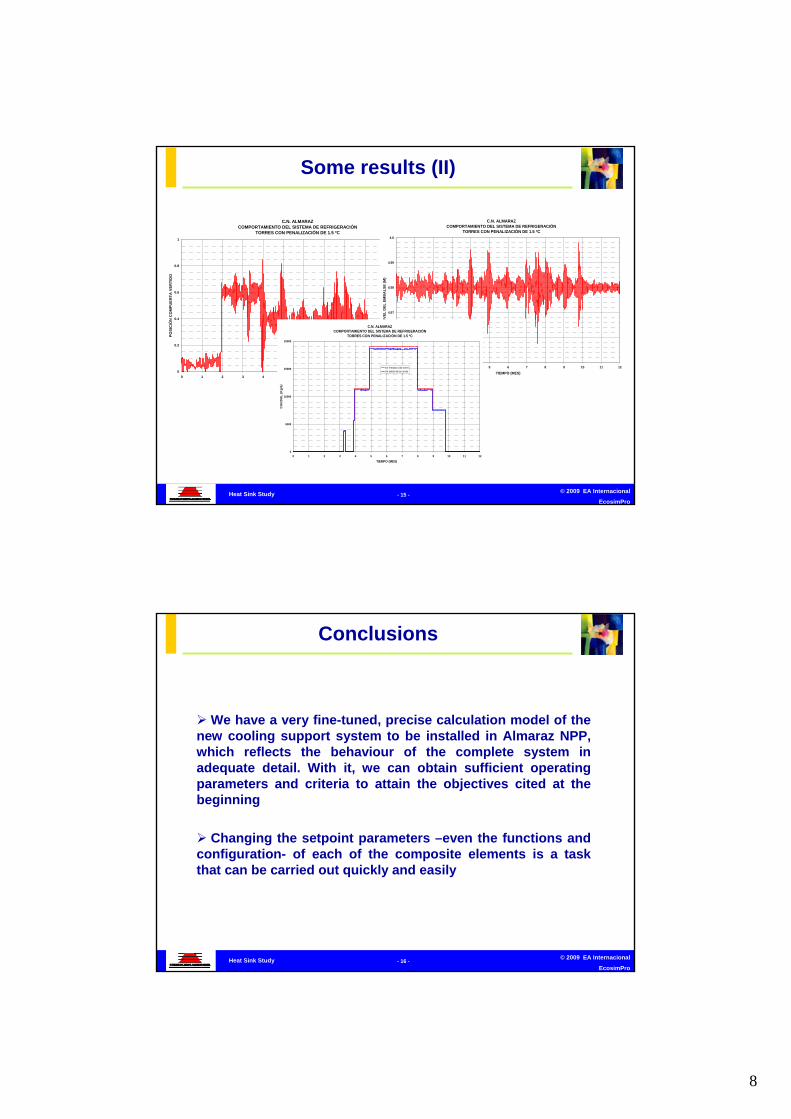
Some results (II)
© 2009 EA Internacional
EcosimPro- 16 -Heat Sink Study
We have a very fine-tuned, precise calculation model of the new cooling support system to be installed in Almaraz NPP, which reflects the behaviour of the complete system in adequate detail. With it, we can obtain sufficient operating parameters and criteria to attain the objectives cited at the beginning
Changing the setpoint parameters –even the functions and configuration- of each of the composite elements is a task that can be carried out quickly and easily
Conclusions
9
© 2009 EA Internacional
EcosimPro- 17 -Heat Sink Study
Its adaptation to models of varying complication from the thermohydraulics point of view is facilitated by some of EcosimPro’s basic advantages:
• The possibility to encapsulate models
• Models are easy to re-use
• Its acausal methodology enables us to use the same components for different studies
• We can create physical models because each component corresponds to a real system component and each connection to a real system connection
Conclusions

1
© 2009 EA Internacional
EcosimPro- 1 -Almaraz NPP Steam Generator Level
Control Study
Empresarios Agrupados Internacional (EAI)
Eusebio Huelamo26 November 2009
Tel: 34 – 91 448 85 98 http: www.ecosimpro.com
ALMARAZ NPP STEAM ALMARAZ NPP STEAM GENERATOR LEVEL GENERATOR LEVEL
CONTROL STUDYCONTROL STUDY
1st Workshop of Energy Simulation Applications using EcosimPro
© 2009 EA Internacional
EcosimPro- 2 -Almaraz NPP Steam Generator Level
Control Study
1. For immediate application: Evaluate the effect that the new feedwater control system has on the SG makeup water following a main line break
2. For subsequent applications: Avail of a feedwater system calculation model which contemplates the new control system in minute detail, which is easy to modify, and which enables us to perform reliable behavioural analyses of the logic-hydraulic assembly in situations or manoeuvres of interest in reasonable times
Objectives
2
© 2009 EA Internacional
EcosimPro- 3 -Almaraz NPP Steam Generator Level
Control Study
Validation of EcosimPro:
It has been necessary to validate the PIPELIQTRAN library used to develop concrete models for Almaraz NPP:
A double validation has been performed through the study of individual components (separated effect problems) and complex components (integral test problems)
Additional Tasks
© 2009 EA Internacional
EcosimPro- 4 -Almaraz NPP Steam Generator Level
Control Study
1. Hydraulic
2. Control
Models

3
© 2009 EA Internacional
EcosimPro- 5 -Almaraz NPP Steam Generator Level
Control Study
Original THICOM Model:
Hydraulic Model
© 2009 EA Internacional
EcosimPro- 6 -Almaraz NPP Steam Generator Level
Control Study
EcosimPro Model

4
© 2009 EA Internacional
EcosimPro- 7 -Almaraz NPP Steam Generator Level
Control Study
Westinghouse Diagram
Control Components (I)
© 2009 EA Internacional
EcosimPro- 8 -Almaraz NPP Steam Generator Level
Control Study
SG_FW_DEM
Control Components (I)

5
© 2009 EA Internacional
EcosimPro- 9 -Almaraz NPP Steam Generator Level
Control Study
FW_RPM
Control Components (II)
© 2009 EA Internacional
EcosimPro- 10 -Almaraz NPP Steam Generator Level
Control Study
FW_VALV_POS
Control Components (III)

6
© 2009 EA Internacional
EcosimPro- 11 -Almaraz NPP Steam Generator Level
Control Study
SG_FW_DEM_LO
Control Components (IV)
© 2009 EA Internacional
EcosimPro- 12 -Almaraz NPP Steam Generator Level
Control Study
FW_VALV_POS_JACM
Control Components (V)

7
© 2009 EA Internacional
EcosimPro- 13 -Almaraz NPP Steam Generator Level
Control Study
EcosimPro Model
© 2009 EA Internacional
EcosimPro- 14 -Almaraz NPP Steam Generator Level
Control Study
Control Detail
EcosimPro Model

8
© 2009 EA Internacional
EcosimPro- 15 -Almaraz NPP Steam Generator Level
Control Study
• The general normal operating parameters (condensate pump suction pressure, heater drain temperatures and flows, steam generator pressure and main steam demand) are imposed as boundary conditions on an initial model in which all controls and equipment work correctly, in order to obtain a steady state continuous operation situation. The result of this analysis is saved in a file which will be used in the next step as a “restart” file.
• Depending on the load, the corresponding model is modified to “disconnect”the control that acts on the equipment whose failure we wish to study, imposing its operating mode on the “experiment” file.
• The signals that generate the main steam flow readings are “disconnected”; information is given manually to the elements that need it assuming that the flow gauges –in a broken state due to great pressure difference– must give a maximum steam flow signal which is false.
• The corresponding case is run using the aforementioned “restart” file as the initial conditions, imposing Westinghouse’s mass discharge values due to the break as a function of time and the rest of the established hypotheses.
Configuration of Experimentsand Method followed for the Analysis
© 2009 EA Internacional
EcosimPro- 16 -Almaraz NPP Steam Generator Level
Control Study
• Failure of one turbine pump at 0% and 30% power• Failure of two turbine pumps at 30% power• Bypass valve failure (initiated with the accident) at 0% and 30%
power• Bypass valve failure (prior to the accident) at 0% and 30% power• Main valve failure (initiated with the accident) at 0% and 30%
power• Main valve failure (prior to the accident) at 0% and 30% power• Main and bypass valve failure (initiated with the accident) at 0%
and 30% power• Main and bypass valve failure (prior to the accident) at 0% and
30% power
Some Analysed Cases

9
© 2009 EA Internacional
EcosimPro- 17 -Almaraz NPP Steam Generator Level
Control Study
Results (I)
© 2009 EA Internacional
EcosimPro- 18 -Almaraz NPP Steam Generator Level
Control Study
Results (II)

10
© 2009 EA Internacional
EcosimPro- 19 -Almaraz NPP Steam Generator Level
Control Study
• We have EcosimPro libraries which have been validated
• We have a calculation model of the new control system installed in Almaraz NPP which is fine-tuned and reflects system behaviour in minute detail
• Changing the setpoint parameters –functions- of each of the constituent elements or their configuration is a task which can be carried out quickly and easily
• Adaptation to models of varying complexity from the thermohydraulics point of view is facilitated by some of EcosimPro’s basic features: encapsulation and ease of reusing models
• Thanks to this, we have succeeded in building an operating model in record time
• It constitutes a great example of the importance it has so that end users have a detailed model –independent of the suppliers- with which they can perform a detailed analyses of the effect that different control strategies or different physical configurations have on key transients
Conclusions

1
© 2009 EA Internacional
EcosimPro- 1 -
Estudio de golpe de ariete en sistema de aguade circulación
Empresarios Agrupados Internacional (EAI)
Laura Arenas26th November 2009
Telephone: 34 – 91 448 85 98 http: www.ecosimpro.com
MontoirMontoir de Bretagne CCGT 435 MWde Bretagne CCGT 435 MW
Calculation of the Hydraulic Transients Calculation of the Hydraulic Transients of the Circulating Water Systemof the Circulating Water System
1st Day of Energy Simulation Applications using EcosimPro
© 2009 EA Internacional
EcosimPro- 2 -
Estudio de golpe de ariete en sistema de aguade circulación
Purpose of the calculation:
Analysis of the system transients on order to verify:
• The design pressure limits of same
• The actuation times of the circulating water pump isolation valves.
• Propose the layout of the system protection elements.

2
© 2009 EA Internacional
EcosimPro- 3 -
Estudio de golpe de ariete en sistema de aguade circulación
Model
© 2009 EA Internacional
EcosimPro- 4 -
Estudio de golpe de ariete en sistema de aguade circulación
EcosimPro graphic tool

3
© 2009 EA Internacional
EcosimPro- 5 -
Estudio de golpe de ariete en sistema de aguade circulación
Features of the model
• Large difference in the pump water suction level, depending on the tides (8 m approximately)
• Use of variable speed drives to vary the frequency of the pumps.
• Variable speed drives modelled by PID controllers on the motors.
• Two experiments per transient, depending on the two levels of suction.
© 2009 EA Internacional
EcosimPro- 6 -
Estudio de golpe de ariete en sistema de aguade circulación
Selection of the operation mode.
• Several preliminary analyses are carried out, corresponding to two operating modes:
– Without allowing air to enter the system
– Opening all the air inlets to the system
• Purpose: to establish the most favourable operation mode, with regard to pressures

4
© 2009 EA Internacional
EcosimPro- 7 -
Estudio de golpe de ariete en sistema de aguade circulación
Transients analyzed
• Trip of two pumps with simultaneous closure of their isolation valves
• Trip of one pump and simultaneous closure of its isolation valve
• Trip of one pump while its isolation valve remains open
– From this preliminary analysis, the following results were obtained:
© 2009 EA Internacional
EcosimPro- 8 -
Estudio de golpe de ariete en sistema de aguade circulación
If air is not allowed to enter the system, the design pressures are exceeded
CCGT MONTOIRSISTEMA DE AGUA DE CIRCULACIÓN
Disparo de dos bombas con cierre de sus válvulas de aislamiento (nivel máximo)
-1
1
3
5
7
9
0 10 20 30 40 50 60
Tiempo (s)
Pre
sión e
n v
álvu
la (bar
g)
11PAB10/AA301 aguas abajo
Preliminary experiments (I)

5
© 2009 EA Internacional
EcosimPro- 9 -
Estudio de golpe de ariete en sistema de aguade circulación
Using all the systenm air inlets, it is evident that the system is incapable of evacuating the air when only one pump is in operation
CCGT MONTOIRSISTEMA DE AGUA DE CIRCULACIÓN
Disparo de una bomba con cierre de su válvula (nivel máximo)
0
10
20
30
40
50
60
70
80
90
0 10 20 30 40 50 60 70 80 90 100
Tiempo (s)
Vo
lum
en d
e ai
re d
el s
iste
ma
(m3)
Volumen de aire caja de agua entrada superior
Volumen de aire caja de agua intermedia superior
Volumen de aire caja de agua salida inferior
Volumen de aire caja de agua salida superior
Preliminary experiments (II)
© 2009 EA Internacional
EcosimPro- 10 -
Estudio de golpe de ariete en sistema de aguade circulación
Conclusions reached from the preliminary experiments
• The transients are carried out by allowing the opening of a vacuum breaker which must be located in the first collector.
• All the remaining air inlets and outlets without possibility of opening.
• Each transient will be studied for each level of suction depending on the tides.

6
© 2009 EA Internacional
EcosimPro- 11 -
Estudio de golpe de ariete en sistema de aguade circulación
Some transients and goals of the syudy (I)
• Trip of one pump and simultaneous closure of the isolation valve
– In this case the following will be analyzed:
– If the closure time of the isolation valve is appropriate for the pump for the tripped pump to be protected and the pressures do not exceed the limits.
© 2009 EA Internacional
EcosimPro- 12 -
Estudio de golpe de ariete en sistema de aguade circulación
Some transients and goals of the syudy (II)
• Trip of one pump while its isolation valve remains open
– On this case, the following will be analyzed:
• Behaviour of the tripped pump and the inverse rotation speed values reached, with no rachet.
• The possibility of keeping the plant in operation if this happens shall be assessed.

7
© 2009 EA Internacional
EcosimPro- 13 -
Estudio de golpe de ariete en sistema de aguade circulación
Most significant results
• Case I: Trip of one pump and simultaneous closure of its isolation valve
© 2009 EA Internacional
EcosimPro- 14 -
Estudio de golpe de ariete en sistema de aguade circulación
CCGT MONTOIRSISTEMA DE AGUA DE CIRCULACIÓN
Disparo de una bomba con cierre de su válvula de aislamiento (nivel máximo)
-1
0
1
2
3
0 10 20 30 40 50 60
Tiempo (s)
Pre
sión e
n v
álvu
la (bar
g)
11PAB10/AA301 aguas abajo
Most significant results: Case I
Maximum level

8
© 2009 EA Internacional
EcosimPro- 15 -
Estudio de golpe de ariete en sistema de aguade circulación
CCGT MONTOIRSISTEMA DE AGUA DE CIRCULACIÓN
Disparo de una bomba con cierre de su válvula de aislamiento (nivel máximo)
0
2
4
6
0 10 20 30 40 50 60 70 80 90 100
Tiempo (s)
Volu
men d
e air
e del s
iste
ma
(m
3)
burbuja de aire en rompedor mh1
Most significant results: Case I
Maximum level
© 2009 EA Internacional
EcosimPro- 16 -
Estudio de golpe de ariete en sistema de aguade circulación
CCGT MONTOIRSISTEMA DE AGUA DE CIRCULACIÓN
Disparo de una bomba con cierre de su válvula de aislamiento (nivel máximo)
0
100
200
300
400
500
600
0 10 20 30 40 50 60
Tiempo (s)
Vel
ocid
ad d
e b
om
bas
(RP
M)
11PAC10-AP001
11PAC20-AP001
Most significant results: Case I
Maximum level

9
© 2009 EA Internacional
EcosimPro- 17 -
Estudio de golpe de ariete en sistema de aguade circulación
CCGT MONTOIRSISTEMA DE AGUA DE CIRCULACIÓN
Disparo de una bomba con cierre de su válvula de aislamiento (nivel mínimo)
-1
0
1
2
3
4
5
0 10 20 30 40 50 60
Tiempo (s)
Pre
sión e
n v
álvu
la (bar
g)
11PAB10/AA301 aguas abajo
Most significant results: Case I
Minimum level
© 2009 EA Internacional
EcosimPro- 18 -
Estudio de golpe de ariete en sistema de aguade circulación
CCGT MONTOIRSISTEMA DE AGUA DE CIRCULACIÓN
Disparo de una bomba con cierre de su válvula de aislamiento (nivel mínimo)
0
2
4
6
0 10 20 30 40 50 60 70 80 90 100
Tiempo (s)
Vo
lum
en d
e ai
re d
el s
iste
ma
(m
3)
burbuja de aire en rompedor mh1
Most significant results: Case I
Minimum level

10
© 2009 EA Internacional
EcosimPro- 19 -
Estudio de golpe de ariete en sistema de aguade circulación
CCGT MONTOIRSISTEMA DE AGUA DE CIRCULACIÓN
Disparo de una bomba con cierre de su válvula de aislamiento (nivel mínimo)
0
100
200
300
400
500
600
0 10 20 30 40 50 60
Tiempo (s)
Velo
cidad
de
bom
bas
(R
PM
)
11PAC10-AP001
11PAC20-AP001
Most significant results: Case I
Minimum level
© 2009 EA Internacional
EcosimPro- 20 -
Estudio de golpe de ariete en sistema de aguade circulación
Trip of one pump with simultaneous valve closure. Conclusion:
• During this event, the main complication appears while adjusting the variable speed drive control.
• Due to the very configuration of the system and the disposition of the flowmeter, there is time variation between the real flow marked by the flowmeter and the location of the pump trip, and in turn of the operating pump response during the incident.
• Regarding the pump rotating speed, please note that no countermeasure is necessary, since there are no negative rotations that could damage the tripped pump.

11
© 2009 EA Internacional
EcosimPro- 21 -
Estudio de golpe de ariete en sistema de aguade circulación
Most significant results
• Case II: Trip of one pump without closure of its isolation valve.
© 2009 EA Internacional
EcosimPro- 22 -
Estudio de golpe de ariete en sistema de aguade circulación
CCGT MONTOIRSISTEMA DE AGUA DE CIRCULACIÓN
Disparo de una bomba sin cierre de su válvula de aislamiento (nivel máximo)
-1
0
1
2
3
4
0 10 20 30 40 50 60
Tiempo (s)
Pre
sión e
n v
álvula
(bar
g)
11PAB10/AA301 aguas arriba
11PAB10/AA301 aguas abajo
Most significant results: Case I
Maximum level

12
© 2009 EA Internacional
EcosimPro- 23 -
Estudio de golpe de ariete en sistema de aguade circulación
CCGT MONTOIRSISTEMA DE AGUA DE CIRCULACIÓN
Disparo de una bomba sin cierre de su válvula de aislamiento (nivel máximo)
0
1
2
3
4
5
6
0 10 20 30 40 50 60
Tiempo (s)
Volu
men
de
air
e d
el s
iste
ma
(m
3)
burbuja de aire en rompedor mh1
Most significant results: Case II
Maximum level
© 2009 EA Internacional
EcosimPro- 24 -
Estudio de golpe de ariete en sistema de aguade circulación
CCGT MONTOIRSISTEMA DE AGUA DE CIRCULACIÓN
Disparo de una bomba sin cierre de su válvula de aislamiento (nivel máximo)
-500
-400
-300
-200
-100
0
100
200
300
400
500
600
0 10 20 30 40 50 60
Tiempo (s)
Velo
cidad
de b
om
bas
(R
PM
)
11PAC10-AP001
11PAC20-AP001
Most significant results: Case II
Maximum level

13
© 2009 EA Internacional
EcosimPro- 25 -
Estudio de golpe de ariete en sistema de aguade circulación
CCGT MONTOIRSISTEMA DE AGUA DE CIRCULACIÓN
Disparo de una bomba sin cierre de su válvula de aislamiento (nivel mínimo)
-2
-1
0
1
2
3
4
0 10 20 30 40 50 60
Tiempo (s)
Pre
sió
n e
n v
álvula
(bar
g)
11PAB10/AA301 aguas arriba
11PAB10/AA301 aguas abajo
Most significant results: Case II
Minimum level
© 2009 EA Internacional
EcosimPro- 26 -
Estudio de golpe de ariete en sistema de aguade circulación
CCGT MONTOIRSISTEMA DE AGUA DE CIRCULACIÓN
Disparo de una bomba sin cierre de su válvula de aislamiento (nivel mínimo)
0
2
4
6
0 10 20 30 40 50 60 70 80 90 100
Tiempo (s)
Volu
men
de
aire
del
sis
tem
a (m
3)
burbuja de aire en rompedor mh1
Most significant results: Case II
Minimum level

14
© 2009 EA Internacional
EcosimPro- 27 -
Estudio de golpe de ariete en sistema de aguade circulación
CCGT MONTOIRSISTEMA DE AGUA DE CIRCULACIÓN
Disparo de una bomba sin cierre de su válvula de aislamiento (nivel mínimo)
-700
-600
-500
-400
-300
-200
-100
0
100
200
300
400
500
600
700
0 10 20 30 40 50 60
Tiempo (s)
Vel
oci
dad
de
bom
bas
(R
PM
)
11PAC10-AP001
11PAC20-AP001
Most significant results: Case II
Minimum level
© 2009 EA Internacional
EcosimPro- 28 -
Estudio de golpe de ariete en sistema de aguade circulación
Trip of one pump without valve closure. Conclusion:
• After preparing this model, the risk of having pumps without ratchets that can rotate freely in the other direction is verified.
• For maximum level, the pump that trips reaches a maximum negative rotation speed of 400 rpm, (73% of the rated rotations).
• For minimum level, the pump that trips reaches a maximum negative rotation speed of -600 rpm, (110% of the rated rotations).

15
© 2009 EA Internacional
EcosimPro- 29 -
Estudio de golpe de ariete en sistema de aguade circulación
Final Conclusions:
• One vacuum breaker will be installed in manhole mh1. Its effective diameter will be 2" with a setflow pressure of 1.01325 bar (absolute pressure).
• It is necessary to establish the flow control parameters in order to give the required response to risky situations that could occur during operation.
• In no case will the pumps be greater than 150% of the rated regime of rotation in the transients studied in which they rotate in inversely.

1
© 2009 EA Internacional
EcosimPro- 1 -Transitorios en el Sistema de Suministro de Gas
Natural de Ciclos Combinados
Empresarios Agrupados Internacional (EAI)
Alfonso Junquera26th November 2009
Telephone: 34 – 91 448 85 98 http: www.ecosimpro.com
Transients in the Combined Transients in the Combined Cycle Natural Gas Supply Cycle Natural Gas Supply
SystemSystem
1st Day of Energy Simulation Applications using EcosimPro
© 2009 EA Internacional
EcosimPro- 2 -Transitorios en el Sistema de Suministro de Gas
Natural de Ciclos Combinados
PURPOSE OF THE STUDY:
• To study the transient behaviour of the pressure in the natural gas supply grid after a turbine trip or load rejection
• To verify compliance with the requirements indicated by the supplier of the gas turbine with regard to the pressure variations at the terminal point of supply
1. Ramp criterion
2. Step criterion
• To verify compliance with any additional requirements from the Owner For example, no trip of a safety interrupt valve after the shutdown of the gas turbine.
Setting out the problem (I)

2
© 2009 EA Internacional
EcosimPro- 3 -Transitorios en el Sistema de Suministro de Gas
Natural de Ciclos Combinados
GENERAL ISSUES in power plants that have more than one gas turbine in parallel
Trip of a GT:
• Start of pressure transient in the system due to sudden reduction in gas flow in one of the lines
• The system (regulation valves + piping volume) is not capable ofhandling the transient, and another turbine could trip.
RMSRMS
GT1GT1
GT2GT2
NGTNGT
NG NG GRIGRIDD
Setting out the problem (II)
© 2009 EA Internacional
EcosimPro- 4 -Transitorios en el Sistema de Suministro de Gas
Natural de Ciclos Combinados
GENERAL ISSUES in power plants that have one gas turbine
GT trip:
• If the system volume is not sufficient, over-pressure could result causing the RMS to trip
RMSRMS GT2GT2NG GRIDNG GRID
Load rejection:
• The sudden reduction of gas flow at the turbine inlet (from 100% to 25%) could cause a pressure transient, causing the turbine to trip.
Setting out the problem (III)

3
© 2009 EA Internacional
EcosimPro- 5 -Transitorios en el Sistema de Suministro de Gas
Natural de Ciclos Combinados
Setting out the problem (IV)
SUPPLIER'S CRITERIA
During transients:
At all times the gas pressure at the turbine inlet between maximum and minimum allowed
Ramp criterion The pressure variation must not exceed a ramp of 1%
per second
Step criterion The pressure step in five seconds must not exceed 5%
OKOK
Complies
Complies
Does not Does not complycomply
Does not Does not complycomply
Not OKNot OK
© 2009 EA Internacional
EcosimPro- 6 -Transitorios en el Sistema de Suministro de Gas
Natural de Ciclos Combinados
NATURAL GAS SYSTEM
NATURAL GAS CONDITIONING EQUIPMENT (I)NATURAL GAS CONDITIONING EQUIPMENT (I)
RMSRMS GT2GT2NG GRIDNG GRIDSupply Line
Distribution Network
Regulation ramp
CONDITIONING EQUIPMENT
CONDITIONING EQUIPMENT
CONDITIONING EQUIPMENT
GT3GT3
GT1GT1
Regulating and Metering Station

4
© 2009 EA Internacional
EcosimPro- 7 -Transitorios en el Sistema de Suministro de Gas
Natural de Ciclos Combinados
Gas supplyGas supply
FILTERINGFILTERINGHEATINGHEATING
REGULATIONREGULATION METERINGMETERING
TO CONDITIONING TO CONDITIONING EQUIPMENT OF THE GTEQUIPMENT OF THE GT
2 lines x 100%2 lines x 100%
NATURAL GAS CONDITIONING EQUIPMENT (II) NATURAL GAS CONDITIONING EQUIPMENT (II)
Regulating and Metering Station
© 2009 EA Internacional
EcosimPro- 8 -Transitorios en el Sistema de Suministro de Gas
Natural de Ciclos Combinados
•Gas filtering and heating before it enters the turbine
•Generally there are several modules:
Filter to eliminate liquids
Scrubber to filter out particles
Water-gas heater and electric heater
Filter Heater
Water-Gas
Heater
Electric ScrubberInletTo the GT
NATURAL GAS CONDITIONING EQUIPMENT (III) NATURAL GAS CONDITIONING EQUIPMENT (III)
Regulating and Metering Station

5
© 2009 EA Internacional
EcosimPro- 9 -Transitorios en el Sistema de Suministro de Gas
Natural de Ciclos Combinados
RMSRMS
Auxiliary Boilers Auxiliary Boilers and Black and Black
StartStart
HEADERSHEADERSLINES TO THE GTLINES TO THE GT
System model in EcosimPro (I)
© 2009 EA Internacional
EcosimPro- 10 -Transitorios en el Sistema de Suministro de Gas
Natural de Ciclos Combinados
RMSRMS 3 x 33%3 x 33%
Regulator Regulator
MonitorMonitor
Regulator Regulator
ActiveActive
Pressure Pressure measurementmeasurement
The pressure setting of the regulators is different on sequential opening
+ 1.5 bar+ 1.5 bar
+ 1.5 bar+ 1.5 bar
+ 0.5 bar+ 0.5 bar
+ 1.5 bar+ 1.5 bar
+ 1.5 bar+ 1.5 bar
PSETPSET
System model in EcosimPro (II)

6
© 2009 EA Internacional
EcosimPro- 11 -Transitorios en el Sistema de Suministro de Gas
Natural de Ciclos Combinados
CONDITIONING EQUIPMENT AND GAS TURBINE
System model in EcosimPro (III)
© 2009 EA Internacional
EcosimPro- 12 -Transitorios en el Sistema de Suministro de Gas
Natural de Ciclos Combinados
The pressure regulation system comprises two regulators:
• Active regulator: Normally regulates
• Monitoring regulator Actuates in the event of failure of the active regulator
Pressure Regulating Valve (I)
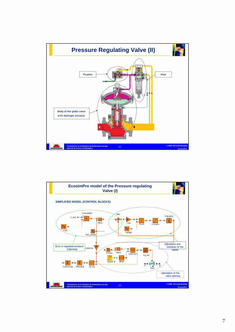
7
© 2009 EA Internacional
EcosimPro- 13 -Transitorios en el Sistema de Suministro de Gas
Natural de Ciclos Combinados
Body of the globe valve
with diafragm actuator
Prepilot Pilot
Pressure Regulating Valve (II)
© 2009 EA Internacional
EcosimPro- 14 -Transitorios en el Sistema de Suministro de Gas
Natural de Ciclos Combinados
SIMPLIFIED MODEL (CONTROL BLOCKS)
Error in regulated pressure Error in regulated pressure (Opening)(Opening)
Calculation and Calculation and limitation of the limitation of the
speedspeed
Calculation of the Calculation of the valve openingvalve opening
EcosimPro model of the Pressure regulating Valve (I)

8
© 2009 EA Internacional
EcosimPro- 15 -Transitorios en el Sistema de Suministro de Gas
Natural de Ciclos Combinados
EcosimPro model of the Pressure regulating Valve (II)
FLUID-MECHANICAL MODEL
© 2009 EA Internacional
EcosimPro- 16 -Transitorios en el Sistema de Suministro de Gas
Natural de Ciclos Combinados
Initial condition:
All 6 turbines are in operation at 100% load.
Start of the transient
At instant t=200 s, one of the gas turbines trips, reducing the gas flow entering the turbine from 100% to 0% in 1 second.
TRIP OF A GAS TURBINE (I) TRIP OF A GAS TURBINE (I)
Simulation in EcosimPro
RMSRMSNG GRIDNG GRID
GT1GT1
GT2GT2
GT3GT3
GT4GT4
GT5GT5
GT6GT6
100%100%
100%100%
100%100%
100%100%
100%100%
100%100%

9
© 2009 EA Internacional
EcosimPro- 17 -Transitorios en el Sistema de Suministro de Gas
Natural de Ciclos Combinados
EVOLUTION OF THE PRESSURE Gas Turbine Inlet Pressure
2300000
2350000
2400000
2450000
2500000
2550000
2600000
2650000
2700000
195 200 205 210 215 220 225 230 235 240 245 250 255 260 265 270 275 280 285 290 295 300
Time (s)
Pre
ss
ure
(P
a a
) FG1_U1_2FG1_U2_1FG1_U2_2FG1_U3_1FG1_U3_2
Simulation in EcosimPro
TRIP OF A GAS TURBINE (II)TRIP OF A GAS TURBINE (II)
© 2009 EA Internacional
EcosimPro- 18 -Transitorios en el Sistema de Suministro de Gas
Natural de Ciclos Combinados
OPENING OF THE VALVES Regulation Valves Stroke
0
10
20
30
40
50
60
70
195 200 205 210 215 220 225 230 235 240 245 250 255 260 265 270 275 280 285 290 295 300
Time (s)
Str
ok
e (
mm
)
Reg Mon 1Reg Mon 2Reg Mon 3Reg Prin 1Reg Prin 2Reg Prin 3
Simulation in EcosimPro
TRIP OF A GAS TURBINE (III) TRIP OF A GAS TURBINE (III)

10
© 2009 EA Internacional
EcosimPro- 19 -Transitorios en el Sistema de Suministro de Gas
Natural de Ciclos Combinados
VALVE SPEED Regulation Valves Stroke's Speed
-2.5
-2
-1.5
-1
-0.5
0
0.5
1
1.5
2
2.5
195 200 205 210 215 220 225 230 235 240 245 250 255 260 265 270 275 280 285 290 295 300
Time (s)
Sp
ee
d (
mm
/s)
Reg Mon 1Reg Mon 2Reg Mon 3Reg Prin 1Reg Prin 2Reg Prin 3
TRIP OF A GAS TURBINE (IV) TRIP OF A GAS TURBINE (IV)
Simulation in EcosimPro
© 2009 EA Internacional
EcosimPro- 20 -Transitorios en el Sistema de Suministro de Gas
Natural de Ciclos Combinados
• FOR THE DESIGN
1. The results of the transients with EcosimPro allow validation of the specified valves in order to comply both with the requirements of the gas turbine supplier and of the owner.
2. To study the alternatives to reduce the maximum pressure during the transient:
• Additional volume required so as to comply with the requirements
• Devices to accelerate the regulation valves
3. In the event of not complying with the requirements of the turbine supplier the design of the RMS can be modified to incorporate control valves instead of self-regulating valves
• FOR OPERATION
1. Using the model it is easy to adjust the set-points of the valves so as to assure their behaviour during transient and static situation.
Conclusions

Designing ITER Tritium Plants with EcosimPro
1st WORKSHOP ON ENERGY SIMULATION APPLICATIONS USING EcosimPro
CANADA (20, 13 GW), INDIA (11+3), ARGENTINA (2+1), RUMANIA (1+1, 650 MW), Pakistan (1), KOREA (4), Japan (“1)
Maximum tritium supply (HWR) for TF is 27 kg !
• A fusion reactor D(T,)n [17.62 MeV/at‐T] consumes tritium at rates of 55.8 kg/GWt‐a of fusion energy
• Production in a CANDU Is 1‐2 Kg/GWt‐year with specific designed Li‐Al targets
• Most optimistic APT extrapolations ~12 kg/GWt‐a (spallation targets or Li/Al targets suitably designed)
• Tritium decays at rates of 4.57% per year
Supply/demand analysis1. Need for a TRITIUM CYCLE IN FUSION TECHNOLOGYTRITIUM CYCLE IN FUSION TECHNOLOGY

WHAT HAPPENED
• Ontario Power Generation (OPG) have 13 of their 20 CANDU reactors operating
• Reactors with operating licence x 40 years
• Recovery rates in 1999: 2.1 kg/a, decreases to 1.7 kg/a in 2005, inst till 2025
• In 2025, the reactors reach the end of their lifetime and tritium production rates fall
• OPG sell 0.1 kg/a to users external to ITER/VNS (price € 70‐120 million per kg)
• Tritium decays at 4.57 % / year
•CANDU lifetime extension to 60 years
WHAT IS NOT HAPPENING:
• Restart of CANDU reactors
• Construction of new CANDU
• Tritium from military programmes entering the civil market
• Irradiation of Li targets in commercial reactors (including CANDU)
• Tritium inventory in 1999: 15 kg
• Early shutdown of CANDU reactors
• Scenarios of D‐D/TBR startup with tritium production
Market Scenario (civil) for Tritium
1. Need for a TRITIUM CYCLE EN IN FUSION TECHNOLOGYTRITIUM CYCLE EN IN FUSION TECHNOLOGY (3)(3)
Projections for Tritium Availability for TNF in the first half of the 21st Century
• In TNF (exp. + Plants) we must generate our own Tritium!• Tritium going to condition strategy to DEMO ! (init. 5‐10 kg) [IFMIF included]
0
5
10
15
20
25
30
1995 2000 2005 2010 2015 2020 2025 2030 2035 2040 2045
Year
Ontario Tritium In
ventory (kg)
HWR/CANDU.w/o Fusion
ITER(confirmed start in 2006)
ITER (start 2005)
+ CTF(>2017)
5 years, 100 MW, 20% avail., TBR 0.65 years, 120 MW, 30% avail., TBR 1.15
10 years, 150 MW, 30% avail., TBR 1.3
1000 MW Fusion,
10 % avail. TBR 0.0
500 MW, 1.5 % avail
• Tritium exhausted by 2025 if ITER operates at 1000 MW fusion power at 10% availability
•EXPERIM. DEVICES (ITER): OPERATING FLEXIBILITY/ROBUSTNESS• POWER PLANTS: ROBUST TBR & CONTROL TECHNOLOGIES
1. Need for a TRITIUM CYCLETRITIUM CYCLE IN FUSION TECHNOLOGYIN FUSION TECHNOLOGY (3)(3)

ITER Needs• Construction in 2005 and duration 8 years, + 4 yr op without tritium
pulse)(per Tgr 389.0T of atoms10 x 6.022
T ofgr 3x
pulse
s 440MWth x 500 x
10 x 1.60MeVx 17.59
T of atom 1 2319-
“Technical Basis for the ITER FDR– part 6.2.5”.
• Operation 6 + (10?) years burning DT of tritium
• 10 a of operation, 3000 pulses/yr (PP ~ 0.3 MWa m‐2 < 3dpa): 11.67 kg11.67 kg
2. 2. Operating PHASESPHASES and OPRATINGOPRATING MODESMODES of ITER (1)(1)
• There will be no additional unforeseen needs for SS• No habrá regeneración (TBR = 0)
• 1.5 % real operating availability: 11751 pulses 4.57 kg
Central
solenoid
DT
RF
NBI
Constant magnetic toroidal field B0 5T
Plasma current
rises Q<1 Fusion Q>1 Q<1
End of sequence
Fusion power
plasma current
Flow of poloidalcoils
fuel entry
Plasma density
density
External warmup
-200 0 pulse duration (s) (~400 ) 600 700 900 1600
Start of sequence
0.4g T
130g T
0.4 g of T per discharge (0.3% of thel T circulating through the vacuum chamber)
DT
2. Need for a TRITIUM PLANT (PdT) TRITIUM PLANT (PdT) iNiN ITERITER (1) (1)
Short pulseShort pulse DT (450 s fusion, 1350 s dwell) DT (450 s fusion, 1350 s dwell) Long pulseLong pulse DT (3000 s fusion, 9000 s dwell) DT (3000 s fusion, 9000 s dwell)
a 200 Pa ma 200 Pa m33 ss‐‐11 (50 depth + 150 peripheral: 100/DT + 44.5/ D(50 depth + 150 peripheral: 100/DT + 44.5/ D22 + 5.5/ T+ 5.5/ T22))

Low burn rate in ITER (max 1 % burn per pulse at peak feed 200 Pa m3 s‐1) close to long confinement pulsed (short pulses 450 s, long pulses 3000 s)
To date, only the JET (UK) and TFTR (USA) have handled tritium for fusion
2. Need for a TRITIUM PLANT (PdT) IN ITERTRITIUM PLANT (PdT) IN ITER (1) (1)
Necesidad de procesado de enormes flujos de efluente Necesidad de procesado de enormes flujos de efluente tritiadotritiado
ITER: also am experiment in the integrated operation of the PdT (system availability operating reality): process demands: feed, pumping, detritiation
ss FEED
NBI+ cryopumps
TBM (regenerator mode)
SS PUMPING
TRITIUM PLANTTRITIUM PLANT
Temporary storage and supply
Separación isotópica
Permanent storeReception external T
Detritiation of water
H2 HTO, T2O
Processing of pumped product Protium (traces D2)
Emission of detritiated gas via VDS
ITER DT operating scenarios (5th ‐10th yr) means processing ~1400 kg (!) of tritiuma leap of 4 orders of magnitude !!!!
FUNCTIONS OF THE PdTFUNCTIONS OF THE PdT
3. Need for a TRITIUM PLANT (PdT) IN ITERTRITIUM PLANT (PdT) IN ITER (1)(1)
process tritiated gaseous flowsprocess tritiated gaseous flows to produce flows to refuel flows and established isotopic compositions
confine tritium x confine tritium x multiplemultiple barriers barriers : primary components boundaries secondary components (“Glove Boxes”) and rooms
detritiation of residual flows, aqueous/gaseous flows and purification of atmospheres innormal/incidental/accidental op prior to emission to atmosphere
PdT‐ITER conception, design and operating bases are based on robust technology* developed and tested for more than 2 decades,with realistic and demonstrable capabilities to control the overall
dynamic inventory of T

MAIN PdT DESIGN CRITERIAMAIN PdT DESIGN CRITERIA
MINIMISE tritium MINIMISE tritium inventoriesinventories(*)(*) in units and systemsin units and systems
OPERATING SAFETY in terms of containment/control of tritium
HIGH DETRITIATION of effluents MINIMUM ACCIDENTAL AND CHRONIC emissions
MINIMUM PRODUCTION OF TRITIATED WASTES (particularly solids)
Costs
3. Need for a TRITIUM PLANT (PdT) TRITIUM PLANT (PdT) iNiN ITERITER (1) (1)
Inventory limits (administrative for licensing)For different types of tritium inventories: trapped/movable, inside/outside the CV
Economic handling of tritium (recovery ABSOLUTELY NECESSARY)Environmental impact of ITER (substantial part)
Environmental impact of ITER (substantial part related with tritiated wastes)
Complexity of system design (at safety levels given) vs tritium costs
Tritium: radioisotope which converts “everything it touches” into radioactive materialContainment barriers and techniquesCounting techniques (dynamic tracking) and control strategies in operation
The French Nuclear Safety Authority: The French Nuclear Safety Authority: obligated dynamic control of T (> 2g) obligated dynamic control of T (> 2g) foresee inputs/outputs from the facilityforesee inputs/outputs from the facility obligation to detect and inform about balance control anomalies obligation to detect and inform about balance control anomalies need to know tritium in one need to know tritium in one ssss in accident eventin accident event
< 1000 gr in < 1000 gr in PFCPFC, : < 330 movable tritium, : < 330 movable tritium < 120 gr in cryopumps foresee inputs/outputs from the facility< 120 gr in cryopumps foresee inputs/outputs from the facility < 700 gr circulating in cycle: < 100 gr in each subsystem< 700 gr circulating in cycle: < 100 gr in each subsystem 250 gr T in hot cells and storage areas250 gr T in hot cells and storage areas 0.7 through cooling loop0.7 through cooling loop
HH2 , 2 , (HD)(HD)
(D(D22)T)T
DTDT
TT22
DD22
OtherOther
POWER SYSTEM POWER SYSTEM LINESLINES
TT22, DT, (D, DT, (D22)T)TArAr, He, N, He, N22, , NeNe, O, O22
BLOWER BLOWER INJECTORSINJECTORS
NEUTRALNEUTRALINJECTORINJECTORBUNDLESBUNDLES
DD22
HH22
SS ANALYTICAL SS ANALYTICAL PLANTPLANT
SS AUXILIARYSS AUXILIARYPLANTPLANT
ISOTOPICISOTOPIC
SEPARATION SEPARATION
SYSTEMSSYSTEMSHH‐‐DD‐‐T MixesT Mixes
DT bedsDT beds
TEMPORARY AND SUPPLY BEDSTEMPORARY AND SUPPLY BEDS
Ar, He, N2, Ne, O2
(D(D22)T beds)T beds
TT22 bedsbeds
DD2 2 tanktank
DD22
9090%T%T22‐‐1010%D%D22
(D(D22)T)T
50%(D50%(D22))‐‐5050%T%T22
PERMANENT STORAGE BEDSPERMANENT STORAGE BEDS
PFCPFC RECOVERY RECOVERY BEDSBEDS
TORUS TORUS CRYOPUMPSCRYOPUMPS
Pure Pure HDTHDT
Pure Pure HDTHDT
IMPURITY IMPURITY DETRITIATION DETRITIATION
SYSTEMSYSTEM
FINALFINALDETRITIATIONDETRITIATION
SYSTEMSYSTEM
ArAr‐‐4141DECAY TANKDECAY TANK
SS DETRITIATION SS DETRITIATION EFFLUENTS (L) EFFLUENTS (L)
ArAr, He,, He,NN22, , NeNe, , CO,COCO,CO22
VDS DETRITIATION VDS DETRITIATION EFFLUENTS (G) EFFLUENTS (G)
MECHANICAL PUMPINGMECHANICAL PUMPING
FRONT FRONT PERMEATORSPERMEATORS
HeHeGLOW DISCHARGEGLOW DISCHARGE
HELIUM PURIFICATIONHELIUM PURIFICATION
((DT)ODT)Oxx , , C(DT)C(DT)yy
Pure Pure HDTHDT
REACTION REACTION CHAMBERCHAMBER
HOT CELLSHOT CELLS
4. BASIC FUNCTIONSBASIC FUNCTIONS “of plant”, GENERAL OUTLINEGENERAL OUTLINE and MAIN UNITSMAIN UNITS (1)
TRITIUM TRITIUM TRANSPORT TRANSPORT CONTAINERSCONTAINERSLoad unitLoad unit
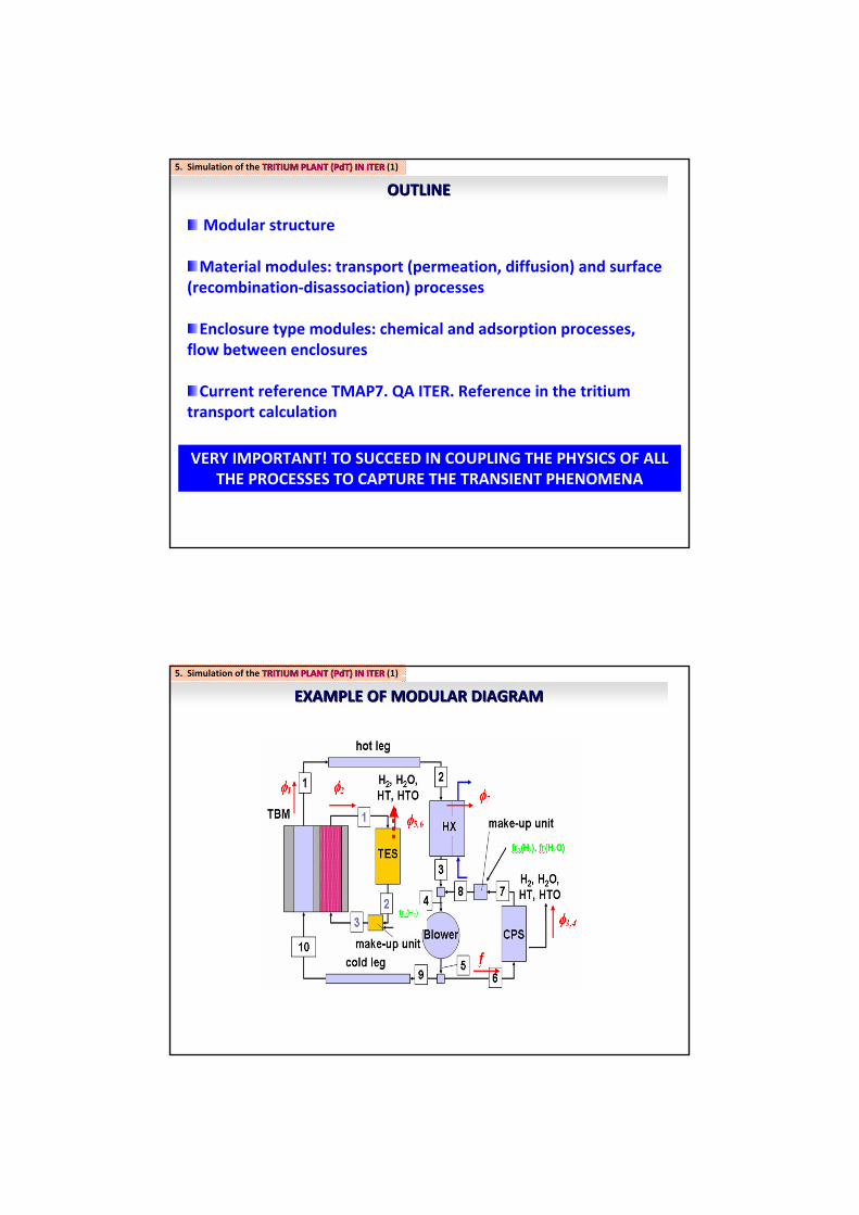
OUTLINEOUTLINE
5. Simulation of the TRITIUM PLANT (PdT) IN ITERTRITIUM PLANT (PdT) IN ITER (1)(1)
Modular structure
Material modules: transport (permeation, diffusion) and surface (recombination‐disassociation) processes
Enclosure type modules: chemical and adsorption processes, flow between enclosures
Current reference TMAP7. QA ITER. Reference in the tritium transport calculation
VERY IMPORTANT! TO SUCCEED IN COUPLING THE PHYSICS OF ALL THE PROCESSES TO CAPTURE THE TRANSIENT PHENOMENA
EXAMPLE OF MODULAR DIAGRAMEXAMPLE OF MODULAR DIAGRAM
5. Simulation of the TRITIUM PLANT (PdT) IN ITERTRITIUM PLANT (PdT) IN ITER (1) (1)

EXAMPLE OF MODULAR DIAGRAMEXAMPLE OF MODULAR DIAGRAM
5. Simulation of the TRITIUM PLANTTRITIUM PLANT ((PdTPdT) ) ININ ITERITER (1) (1)
PebblesPebbles HCSEncl 1
ISS WDS
fCPS
gTc1(t)
c2(t)
PGEncl 2
fCPS
BdryEncl 1
frfr22(H(H22)) frfr2 2 (H(H22O)O)
c3(t)
frfr11(H(H22)) frfr11(H(H22O)O)
ISS WDS
CURRENT SITUATIONCURRENT SITUATION
5. Simulation of the TRITIUM PLANT (PdT) IN ITERTRITIUM PLANT (PdT) IN ITER (1)(1)

EcosimProEcosimPro
5. Simulation of the TRITIUM PLANT (PdT) IN ITERTRITIUM PLANT (PdT) IN ITER (1)(1)
EcosimProEcosimPro
5. Simulation of the TRITIUM PLANT (PdT) IN ITERTRITIUM PLANT (PdT) IN ITER (1) (1)

EcosimProEcosimPro
5. Simulation of the TRITIUM PLANT (PdT) IN ITERTRITIUM PLANT (PdT) IN ITER (1)(1)
ADVANTAGES of EcosimProADVANTAGES of EcosimPro
5. Simulation of the TRITIUM PLANT (PdT) IN ITERTRITIUM PLANT (PdT) IN ITER (1) (1)
Modular structure. Object‐oriented, acausal language (EL)
Library of modules common to all problems of interest
CIEMAT: reference on tritium transport simulation in the TBM‐European Consortium
Need for a tritium transport code in ITER:• For designing systems in the previous phase• To extrapolate results in the different ITER stages for the next experiments• To utilise results for future devices
PLACE A SPANISH CODE AS REFERENCE FOR A FUSION REACTOR!

THANK YOU VERY MUCH!
1st WORKSHOP ON ENERGY SIMULATION APPLICATIONS USING EcosimPro