Embed Size (px)
Citation preview

Copyright c© 2007 Tech Science Press FDMP, vol.3, no.2, pp.115-128, 2007
Modeling the Flow of Molten Steel in a Tundish Containing an InclusionFiltering Trap
A.K. Plappally1, M.A.R. Sharif1, and R.C. Bradt2
Abstract: A novel physical chemical filtrationprocess in a tundish for removal of inclusion par-ticles from molten steel is proposed and analyzed.The considered inclusion particles are mainlycomposed of the minerals alumina (Al2O3) andspinel (MgAl2O4), which have an affinity to ad-here (on contact) to an inclusion trap. An in-dustrial tundish is considered and modified witha zigzag channel block insert installed across themolten steel flow so that when the molten steelflows through the zigzag channels, the inclusionparticles are driven into contact with the chan-nel surfaces by increased recirculation and turbu-lence. The inclusions will bond with the surfacesand be removed from the molten steel. The flowbehavior in a fully three-dimensional model ofsuch a tundish, with and without the incorporationof the zigzag channels, is then modeled and dy-namically simulated. The flow patterns and par-ticle trajectories are then computed and criticallyanalyzed leading to the conclusion that the pro-posed filtering system is practically feasible.
Keyword: Tundish, inclusion particles, inclu-sion removal, zigzag channel.
Nomenclature
dp Diameter of the inclusion particleg Acceleration due to gravityh Channel spacingk Turbulent kinetic energymp Particle massp Mean fluid pressure
1 Aerospace Engineering and Mechanics Department, TheUniversity of Alabama, Tuscaloosa, Alabama 35487-0280, U.S.A.
2 Metallurgical and Materials Engineering Department, TheUniversity of Alabama, Tuscaloosa, Alabama 35487-0202, U.S.A.
Re Reynolds numbert Timeui Mean velocity componentsu′i Fluctuating velocity componentUf Mean velocity vector of the fluid phaseUr Fluid velocity vector relative to the particleUp Velocity vector of the particle
Greek Symbols
μ Viscosityμt Turbulent eddy viscosityρ Densityρ f Density of the fluid phaseρp Density of the particleθ Zigzag angle for the channelωp Spinning velocity vector for the particle
1 Introduction
One of the most critical aspects of steel qualityis its cleanliness with regard to inclusion con-tent. Inclusion particles in cast steel may origi-nate from various sources within the molten steelbefore casting. Steel producers know that thepresence of inclusions directly affects the qual-ity of their products through the generation ofdefects, in the hot workability of the steel, andas the sources for fatigue crack initiation. Inclu-sions are also a serious problem in the formationof accretions in submerged entry nozzles (SENs)at tundish outlets. Clean steel, however, is usu-ally defined by consumer demand rather than interms of composition or inclusion levels becausethis definition depends on the final application ofsteel products. While total elimination of inclu-sion particles from steel is probably an unrealisticgoal, the decrease, removal, and control of the in-clusions in the cast steel is an important aspect inall steel production processes.

116 Copyright c© 2007 Tech Science Press FDMP, vol.3, no.2, pp.115-128, 2007
Physical sieving of the inclusion particles isimpractical because the sieve will be rapidlyclogged. Historically, various filtering tech-niques have been applied for the removal of in-clusions from the molten steel in the tundish.These include foams or porous filters (Ichibashi,1986) and processes utilizing various physicalproperties such as the bubble trapping of parti-cles (Chevrier, 2000), floatation (He and Sahai,1990), electro-magnetic separation (Taniguchiand Brimacombe, 1997), etc. However, thesetechniques produced limited success in attain-ing the required level of inclusion removal. Thesearch for an alternative effective inclusion re-moval system from the molten steel in the tundishis a continuing and an active research area. Thepresent article considers an alternative inclusionremoval system from the molten steel while it isin the tundish.
A large portion of the inclusion particles inaluminum-killed molten steel poured into thetundish consists of the minerals spinel (MgAl2O4)and alumina (Al2O3) which are high meltingpoint oxides that have a very strong affinity toadhere/bond to oxides (Itoh, Hino, and Ban-ya,1997) as evident by the formation of accretions inthe SEN. This bonding or chemical adherence isto be exploited in the proposed filtration/trappingtechnique for removing the inclusions from thesteel. A refractory block of vertically stackedzigzag channels will be strategically placed acrossthe steel flow direction within the tundish. Thezigzag channel block may either be manufacturedwholly of spinel or the channel surfaces may becoated with spinel. The concept is that the steelflow through the tortuous channels induces recir-culation and increased turbulence so that the in-clusion particles come in contact with the channelsurfaces and adhere to them. Once the particles hitthe channel surface, it is expected that they willchemically bond with the surface thereby beingremoved from the molten steel. This phenomenonactually occurs during the clogging of the SENsby the formation of accretions at the SEN exit. Inprinciple, the zigzag channel block may be physi-cally removed from the tundish and replaced witha new block once the old block becomes clogged
with trapped inclusions.
The success of physiochemical entrapment of in-clusion particles from molten steel in the tundishmust be evaluated in actual field trials with an in-dustrial tundish. However, before the field trial,preliminary modeling studies of the actual designof the zigzag channels, the flow behavior of thesteel with the channels, and the resulting trajec-tories of the inclusion particles are necessary toassess the potential effectiveness of the filteringsystem. This can be accomplished using numeri-cal simulation/modeling of the tundish equippedwith the zigzag channel inclusion trapping sys-tem. The present article describes such a pre-liminary numerical study about the feasibility ofincorporating a proposed inclusion removal sys-tem in an actual industrial tundish. The flowbehavior of the molten steel and the trajectoriesof the inclusion particles within the tundish andthrough the zigzag channels are numerically com-puted and the results are graphically presented.
Mathematical/numerical models for tundish flowanalysis have been previously employed by sev-eral researchers. Chakraborty and Sahai (1991)in a study of the effects of turbulent collisions,re-oxidation, flotation, and inclusion size distri-bution, predicted the removal of alumina inclu-sions from molten steel in a continuous cast-ing tundish. Shen, Khodadadi, Pien, and Lan(1994) completed turbulence measurements andalso finite-element simulation for the tundish flowof aluminum and found favorable agreement be-tween the experiment and prediction. Sheng andJonsson (1999) conducted water modeling of thetundish flow and applied a three-dimensional tran-sient mathematical model to observe significantbuoyancy effects. Lopez-Ramirez, Morales, andSerrano (2000) performed numerical simulationof the effects of buoyancy forces and flow con-trol devices on fluid flow and heat transfer ina tundish. Javurak, Kaufmann, Gerhard, andPhilipp (2002) noticed that recirculation volumesand turbulent particle diffusion were the rea-sons for unsatisfactory particle separation. Theynoted that the turbulent shear forces in the moltensteel affects the coagulation of inclusions in thetundish. Nakashima, Tanaka, Fukuda, Kiyose,

Modeling the Flow of Molten Steel 117
and Yamada (2003) observed that in an actualtundish the turbulence dissipation rate is largestnear the inlet nozzle, but extremely small in allother regions. They studied various design param-eters such as the inlet shroud immersion depth,different outlet positions, and different designs ofthe pour boxes for flow optimization with variousturbulence models. Jha and Dash (2002, 2004)evaluated different turbulence models of the k−εfamily for the prediction of tundish flow and con-cluded that the RNG k− ε model performs betterthan the other variants of the k − ε model. Forother results on solidification problems (in othergeometries) and related possible numerical ap-proaches, the reader may consider the followingrecent works: Amberg and Shiomi (2005), whostudied the effect of various types convection ongeneric solidification problems; Ludwig, Gruber-Pretzler, Wu, Kuhn and Riedle (2005), who nu-merically investigated (using the FLUENT CFDcode) the formation of macrosegregations duringcontinuous casting of Sn-Bronze and discussedthe impact of different convection types (inletflow, thermal and solutal buoyancy flow, and feed-ing flow); Abhilash, Joseph, and Krishna (2006)who used artificial neural networks algorithms forthe prediction of dendritic parameters and macrohardness variation in permanent mould castings;Hong, Zhu, and Lee (2006) and Narski and Pi-casso, (2007) who introduced new models for thenumerical simulation of dendritic growth in alloysolidification with melt convection, etc.
The present study consists of two parts. The firstis the hydrodynamic design optimization of thezigzag channel. It is performed numerically con-sidering the two-dimensional geometry of a sin-gle zigzag channel. Suitable channel design is de-cided on the basis of results of a parametric studyand examination of the flow behavior and particletrajectories within the channel. In the second part,a numerical model for a three-dimensional indus-trial tundish is developed. Steel flow and particletrajectories in the tundish are computed and ana-lyzed. Finally, the tundish flow model is modifiedby inserting a vertically stacked block containingmultiple zigzag channels with the same geometri-cal design obtained in part one of the study. The
flow and particle trajectory computations are thenrepeated. The results are analyzed and the feasi-bility of the proposed inclusion trapping/removaltechnique is discussed.
The tundish used in the model is a delta tundishthat is symmetrical about the mid-plane throughthe inlet shroud. Because of this symmetry onlyhalf of the tundish is modeled. The geometry ofthe symmetric half of the tundish and its modifiedversion with the block of zigzag channel insert inplace is shown in Fig. 1.
Figure 1: The modeled tundish schematic show-ing the geometric features; the bottom figureshows the tundish with the zigzag channel blockinsert in place.
The main tundish tank is in the longitudinal di-rection while the pouring block containing theinlet shroud is projected in the span wise direc-tion. It is separated from the main tundish by aweir. The entering steel flow is poured throughthe inlet shroud onto the pouring block. The steelflow passes beneath the weir and is divided intotwo equal parts and turns longitudinally and flowsover a span-wide small dam into the main tundish
118 Copyright c© 2007 Tech Science Press FDMP, vol.3, no.2, pp.115-128, 2007
tank, then exits through the two outlet strands atthe bottom on each side. One of the outlets is lo-cated near the dam while the other outlet is fur-ther downstream close to the end wall. The zigzagchannel inclusion trap is inserted at a strategic po-sition in between the two outlets in the modifiedtundish model.
In order to impose a Cartesian coordinate systemonto the tundish geometry, the x direction is as-signed parallel to the longitudinal direction of themain tundish cavity. The y direction is assignedspan-wise and z direction is the vertical. The ori-gin of the coordinate system is positioned at theintersection of the lower edge of the symmetryplane and the vertical mid-plane through the maintundish cavity, hence y = 0 on that plane. Thelongitudinal half length of the tundish is 2.79 m(110 in.) while the overall tundish height is 1.07m (42 in.). The span-wise bottom and top widthsof the main cavity are 0.4318 m (17 in.) and 0.668m, (26.3 in.), respectively. The sidewalls and endwalls of the main tundish cavity are slightly in-clined (about 18o with the vertical).
2 Mathematical formulation
2.1 Governing equations for fluid motion
The governing equations for the incompressibleflow consist of the conservation of mass and theReynolds averaged Navier-Stokes (RANS) equa-tions. They are written in the indicial notation asthe following:
∂ui
∂xi= 0 (1)
∂ (ρui)∂ t
+∂ (ρuiuj)
∂x j= ρ f i+
∂∂x j
[−pδi j + μ
(∂ui
∂x j+
∂u j
∂xi
)−ρu′iu′ j
](2)
where ui are the mean velocity components, xi arethe coordinate directions, ρ is the fluid density, tis the time, f i is the body force per unit mass, pis the mean pressure, δi j is the Kronecker delta,μ is the fluid dynamic viscosity, and u′i are thefluctuating velocity components. The Reynolds
stresses in the right hand side of Eq. (2) are:
−ρu′iu′j = μt
(∂ui
∂x j+
∂u j
∂xi
)− 2
3ρkδi j (3)
where μt is the turbulent eddy viscosity and kis the kinetic energy of turbulence. Applyingthe standard k− ε model (Launder and Spalding,1974), the eddy viscosity is given as
μt = ρCμk2
ε(4)
where ε is the turbulence dissipation. The kineticenergy of turbulence, k, and its dissipation rate, ε ,are obtained by solving their respective transportequations whose modeled forms are given as
∂ (ρk)∂ t
+∂ (ρkuj)
∂x j
=∂
∂x j
[(μ +
μt
σk
)∂k∂x j
]+Pk −ρε (5)
and
∂ (ρε)∂ t
+∂ (ρεu j)
∂x j
=∂
∂x j
[(μ +
μt
σε
)∂ε∂x j
]+C1εPk
εk−C2ερ
ε2
k(6)
where the production term Pk =−ρu′iu′j (∂uj/∂ui). The model constants inEqs. (5) and (6) are; Cμ = 0.09, C1ε = 1.44,C2ε = 1.92, σk = 1, and σε = 1.3. Standard wallfunction prescriptions (Launder and Spalding,1974) at the wall are used to solve the equations.
2.2 Governing equation for particle motion influid
Particle motion in a fluid is governed by the La-grangian equation of motion
mp∂Upi
∂ t= FWi +FDi +FPi +FSLi +FMLi (7)
where mp is the mass of the particle, Up is theparticle velocity vector, FW is the body force termexpressing the difference between the weight andthe buoyancy force on the particle, FD is the drag

Modeling the Flow of Molten Steel 119
force, FP is the pressure gradient force, FSL is theSaffman lift force, and FML is the Magnus liftforce. The subscript index i is the tensor indexand stands for the ith coordinate direction.
The body force is given by
FWi =π6
d3p(ρp −ρ f )gi (8)
where giis the component of gravitational accel-eration in the ith direction.
The drag force is given by
FDi =12
ρ fUri|Uri|ApiCD (9)
where ρ f is fluid density, Ur is the relative fluidvelocity with respect to the particle, Api is thefrontal area of the particle as seen from the ithdirection, and CD is the drag coefficient. The rela-tive fluid velocity vector is given by Ur = Uf −Up
where Uf is the fluid velocity vector. The ith com-ponent of Ur is used in Eq. (9). The particle shapeis considered spherical for which the drag coeffi-cient, CD, is given by 24/Repi. This assumes thatthe particle Reynolds number, Repi, is very small.The particle Reynolds number is defined in termsof the relative velocity (Uri) and particle diame-ter (dp) as ρ fUridp/μ . Other prescriptions for CD
over a wide range of Reynolds number are avail-able in Clift, Grace, and Weber (1978).
The pressure gradient force on the particle isgiven by
FPi = −(π/6)d3p (∂ p/∂xi) (10)
Small particles in a shear field experience a liftforce perpendicular to the flow direction of thefluid phase. This lift originates from the inertia ef-fects in the viscous flow around the particle. Theexpression for the inertial shear lift was first pre-sented by Saffman (1965). It is written in the fol-lowing form (Ran, Zhang, Tang, and Xin, 2006),
FSLi = 1.615(ρμ)0.5d2pUr j
∣∣∣∣∂Ur j
dxi
∣∣∣∣0.5
sgn
(∂Ur j
dxi
)
(11)
where the “sgn” term in the right hand side is ei-ther 1 or -1 depending on whether the derivativeterm in its argument is positive or negative.
Local flow vorticity may cause the particles tospin. For spinning particles in a fluid stream, anadditional force perpendicular to the streamwisedirection is created. This is called the Magnus liftforce. The Magnus lift force on the particles spin-ning at an angular velocity vector, ωp, initiatedby the fluid rotation is expressed as (Lun and Liu,1997)
FML =12
ρ f (Ur ·Ur)πd2
p
4CML
ωp ×Ur
|ωp| |Ur| (12)
The angular velocity vector of the particle canbe obtained from the local vorticity as ωp =(1/2)∇×Uf and the coefficient CML is given by
CLM = dp |ωp|/
|Ur| (13a)
if Rep ≤ 1, and
CLM = dp |ωp|/
|Ur|(0.178+0.822Re−0.522
p
)(13b)
if 1 < Rep < 1000.
It is to be noted that the ith component of FML
must be used in Eq. (7) and Rep is defined asρ fUrdp/μ .
The particle trajectories are also affected by turbu-lent eddies which can be incorporated by numer-ically generating the fluctuating velocity compo-nents u′i, and adding those to the local mean fluidvelocity components, Ufi, for every time step in-tegration of Eq. (7) [Schwarze, Obermeier, andJanke (2001) and Varga-Zamora, Morales, Diaz-Cruz, Palafox-Ramos, and Demedices (2003)].Therefore, the inclusion particles will be moredispersed and the chances of the particles impact-ing the channel surfaces will be increased. Thiseffect will also aid the inclusion particles in get-ting out of the “closed streamlines” encompassingthe recirculation regions. The fluctuating velocitycomponents can be generated as u′i = ξ
√k where
ξ is the product of a random number between -1and 1 and an empirical constant. That turbulentdispersion effect, however, has not been consid-ered in the present study.

120 Copyright c© 2007 Tech Science Press FDMP, vol.3, no.2, pp.115-128, 2007
2.3 Details of the numerical process
The governing equations were solved through theapplication of the commercial computational fluiddynamics code, CFD-ACE+T M (ESI-CFD, 2006).The flow domain was divided into small finite vol-ume cells with an unstructured tetrahedral mesh.The governing RANS equations and the trans-port equations for k and ε were integrated overeach cell to generate a linear system of algebraicequations. These were then solved sequentially.The convective fluxes in the transport equationswere calculated using the second-order upwindscheme while the diffusive fluxes are calculatedusing the central differencing scheme. The linearsystem for each transport equation was solved it-eratively until convergence when the residuals arevery small for each equation. The pressure veloc-ity coupling was achieved using the well knownSIMPLE method (Patankar, 1979). A time march-ing procedure with first-order accurate forwarddifferencing time integration was applied to reachthe steady-state solution until the variation of eachvariable between two successive time-steps is in-significant over all cells.
For the simulations, the density and viscosity ofmolten steel was specified to be 7000 kg/m3 and0.0055 Pa s, respectively. An assumed tempera-ture of 1875 K was used.
The particle trajectories were calculated by ac-tivating the relevant component of the CFD-ACE+TM code. Once the steady-state hydrody-namic field was solved, it was then frozen and theparticles were introduced into this hydrodynamicfield with the local initial velocity for the specificpoint of introduction. Time integration of Eq. (7)governing the particle motion was then used tocalculate particle locations for each particle us-ing small time steps. The locations were thenjoined by a curve to display the particle trajecto-ries. No chemistry/chemical kinetics model forthe particle-particle coagulation/agglomeration orparticle to wall adsorption was used to computethe particle trajectories. For the particle trajec-tory calculation, one way coupling was assumed,meaning the particle motion is affected by the hy-drodynamic field, but the hydrodynamic field isnot affected by the particle motion. This is a
valid assumption since the particle distribution inthe molten steel is a very dilute one of well dis-persed particles. Also particle to particle collisionwas not considered in the calculations. However,particle to wall collision was considered throughthe use of a coefficient of restitution, which hasa value between 0 and 1. When the coefficientof restitution is zero, it is a fully plastic collisionin which case the particle is assumed to stick tothe wall after collision. On the other hand if itis 1, it is a fully elastic condition in which casethe particle bounces back with the same speed asbefore the collision. The fully plastic conditionfor the particle to channel wall collision by set-ting the coefficient of restitution to 0 will be usedlater to simulate the bonding of the particles withthe channel walls in lieu of any model to describethe inclusion capture rate. In all trajectory calcu-lation, spherical particles of 1-100 μm diameterwith a mass density of 4000 kg/m3 were consid-ered. This density is representative of typical ox-ide inclusion particles.
3 Results and Discussion
3.1 Zigzag Channel Design
As mentioned in the introduction, the zigzagchannel insert in the tundish is the core of the pro-posed inclusion filtering/trapping technique. Theobjective is to utilize the increased recirculationand turbulence of the molten steel while passingthrough the zigzag channel to bring the inclusionparticles in contact with the channel surfaces. Theinclusions are then expected to chemically reactwith the channel surface and bond to it and thusbe trapped. It is essentially duplicating the con-ditions which create the accretions at the SENexit. As such, a detailed simulation of the flow be-havior and particle trajectories through the zigzagchannel is required in order to optimize the designof the channel configuration which will be used inan actual tundish. First, a two-dimensional chan-nel design, as shown in Fig. 2, is adopted toevaluate its effectiveness even though the actualtundish flow is three-dimensional. This, however,is not a gross simplification since the flow throughthe three-dimensional zigzag channel will be basi-

Modeling the Flow of Molten Steel 121
cally a two-dimensional one, i.e., the variation inthe span-wise direction within the channels willbe insignificant. This particular configuration forthe zigzag channel was chosen to facilitate theease of fabrication of the channel insert and tominimize the space for the placement of the insertin the existing tundish.
The channel is to be placed within the tundishwhere the general flow direction is upward andclosely matches the entry channel angle. Thisis to be determined by examining the three-dimensional simulation of the tundish flow with-out the presence of the zigzag channel. Thezigzag channel exit is directed upward so thatthe exit flow reaches the slag layer and any ofthe remaining inclusion particles that escape be-ing trapped by the channel have an opportunity toreact with the slag and be removed there as in thecase for the standard float-out method of inclusionremoval.
Two important geometric parameters for the chan-nel design/optimization study are the channelspacing, h, and the zigzag angle, θ , as shown inFig. 2. The study was performed through numeri-cal simulation of the steel flow through the chan-nel with the calculation of the particle trajectoriesfor various combinations of these basic geomet-ric parameters. Results were compared and an-alyzed and an optimum pair of these parameterswas determined for the channel design which wasused later in the three-dimensional simulation ofthe actual industrial tundish.
In the flow simulation, no-slip boundary condi-tions were used at the channel walls and con-stant pressure conditions were specified at theoutlet. The inlet velocity components werederived/extracted from the three-dimensionaltundish (without the zigzag channels) flow simu-lation at the location where the channel insert wasto be placed. A systematic grid refinement studywas conducted to obtain the optimum mesh dis-tribution. The nodes were clustered towards thechannel walls. Four different channel spacings,0.0127, 0.0254, 0.0381, and 0.0508 m (0.5, 1, 1.5,and 2 in.), and four different zigzag angles (30˚,45˚, 60˚, and 70˚) were considered resulting in atotal of 16 different simulations.
Figure 2: Schematic diagram of the two-dimensional zigzag channel.
The flow streamlines for each of the 16 chan-nel configurations are shown in Fig. 3 where itis observed that the flow recirculation occurs atthe vertices of the zigzag channel and on the op-posite walls immediately downstream of the ver-tices. The extent of the recirculation regions in thedomain increases with increasing passage widthfor each particular zigzag angle. Excessive recir-culation within the channel will be detrimental tothe objective of bringing the particles into contactwith the channel surfaces. A representative es-timate of the percent recirculation volumes com-pared to the total volume within the channel with a0.0254 m (1 in) spacing for various zigzag anglesis presented in Table 1. The estimate was com-pleted by plotting the streamlines on a fine graphpaper and counting the number of small squaresencircled by the recirculation bubbles. From theseresults it is noticed that while the recirculationvolume is a maximum for the 45˚ angle, it is sim-ilar to that for the 60˚ and 70˚ zigzag angles.
For the optimum channel design, the pressuredrop across the channel must not be excessive.The pressure drop, as a function of the zigzag an-gle, θ , is presented for various passage spacingsin Fig. 4. While the pressure drop is not stronglyaffected by the passage spacing; it increases sig-nificantly with the zigzag angle. The pressuredrop beyond a 60˚ zigzag angle seems to be ex-cessive.
The most important feature to consider for the de-sign of the zigzag channel to fulfill the objectiveof this research is the particle trajectory history

122 Copyright c© 2007 Tech Science Press FDMP, vol.3, no.2, pp.115-128, 2007
h = 2in h =1.5 in
h = 1 in h = 0.5 in
Figure 3a: Streamlines in the zigzag channel, θ =30˚.
h = 2 in h = 1.5 in
h =1 inh= 0.5 in
Figure 3b: θ =45˚.
h = 2 in h = 1.5in
h = 1 in h = 0.5 in
Figure 3c: θ =60˚.
h = 2in h = 1.5 in
h = 1 in h = 0.5 in
Figure 3d: θ =70˚.
through the channel. To this effect the trajec-tories of particles inside the channel were deter-mined by applying the particle dynamics equation[Eq. (7)]. The particle trajectories for a channelwith a 0.0254 m (1 in) spacing and 60˚ angle areshown in Fig. 5. To understand the effects of theparticle size on the trajectories, the diameter of theparticles were varied as 25, 50, 75, and 100 μm.Particle trajectories depend upon the flow field inthe zigzag channel and the various forces includ-ing the buoyancy force exerted on the particle. Ingeneral, larger particles tend to rise to the top sur-face of the channel near the inlet section which isdesirable for the objective. This can be directlyattributed to the larger buoyancy force exerted onthe larger size particles. Smaller particles, experi-encing lesser buoyancy force, tend to flow alongwith the fluid and then exit through the channeloutlet. However, many smaller particles impact
the channel wall especially on the second inclinedtop surface and the third inclined bottom surfaceduring their travel through the zigzag channel.
Table 1: Recirculation volume estimates in per-cent of total channel volume for a channel with 1inch spacing.
Zigzag angle Percent recirculation volume30˚ 7.6545˚ 20.1460˚ 16.2370˚ 16.31
Considering the effects of various geometric pa-rameters such as the zigzag angle and passagespacing and fluid dynamic factors such as the re-circulation volume, particle behavior, and pres-sure drop across the channel, a channel having

Modeling the Flow of Molten Steel 123
Figure 4: Pressure drop across the channel.
d = 100 μm d = 75 μm
d = 50 μm d = 25 μm
Figure 5: Particle trajectories in the zigzag chan-nel with 1 inch spacing and 60˚ angle.
a zigzag angle of 60˚ with a passage spacing ofabout 0.0254 m (1 in) is a near optimum chan-nel design for effective chemical trapping of theinclusions. As such, this configuration of thezigzag channel was recommended for implemen-tation in the complete three-dimensional model ofthe tundish flow simulation.
3.2 Three-dimensional tundish
Two different numerical models; one of the exist-ing tundish and the other of the tundish with thezigzag channel block in place, were considered.The hydrodynamic field in the existing tundishwas first calculated and analyzed to understandthe overall tundish flow behavior and to identify astrategic location for the placement of the zigzagchannel block within the tundish.
The unstructured tetrahedral meshes for both
models, as shown in Fig. 6, were generated bythe mesh generation module of the CFD-ACE+T M
code. A dense mesh was employed near to the in-let shroud, within the pour pad, near to the outletnozzles, and near all of the walls of the tundish.The intense computational demand of these didnot allow a systematic grid refinement study to beperformed. However, after few preliminary trials,a mesh with ∼150,000 cells was deemed satisfac-tory for the feasibility study as the quantitative ac-curacy was not a major concern at this point.
Figure 6: Mesh for tundish models; top –withoutthe zigzag channel, bottom– with the zigzag chan-nel block.
A uniform volumetric flow rate of 0.00355 m3/sobtained from real tundish data was specified atthe inlet. This translated to a uniform inlet veloc-ity of 0.628 m/s downward with an inlet Reynoldsnumber of ∼40,000. Constant pressure (0.0 Pa)conditions were specified at the outlet. No-slipconditions were imposed at all of the walls exceptfor the top surface and the symmetry plane wherezero shear stress and zero normal velocity condi-tions were imposed (Ilegbusi and Szekely, 1987).Isothermal conditions were assumed and as suchit was not necessary to solve the energy equation.

124 Copyright c© 2007 Tech Science Press FDMP, vol.3, no.2, pp.115-128, 2007
3.2.1 Tundish flow without the zigzag channelinsert
Within the pour pad chamber of the tundish,which is contained by the weir, the fluid jet fromthe inlet shroud impinges on the bottom, spreadsoutward radially, bounces back ascending near tothe chamber walls, hits the top surface, goes downagain, and ultimately exits the pour pad chamberthrough the opening beneath the weir. This pro-duces a vigorous turbulent intermixing of the fluidand inclusion particles within the inlet chamber.This is depicted by the streamtrace plots withinthe pour pad chamber using mass less particles ofnegligible diameter released at the inlet. This pat-tern is shown in Fig. 7.
Figure 7: Streamtrace plots within the pour pad.
The overall flow pattern throughout the tundishcan be visualized in the sample streamtrace plotspresented in Fig. 8. A strong helical formof motion of the fluid before its entry into themain tundish chamber is noticeable. In the maintundish cavity, however, the flow does not appearquite as erratic as it is in the inlet zone. This isbecause of the large reduction of the flow velocitymagnitude.
As expected, the geometry of the tundish furni-ture has a profound influence on the flow behav-ior of the molten steel within the tundish. Thepurpose of the small span-wise dam at the entryto the main tundish cavity is to prevent the moltensteel from going directly to the outlet nozzles andshort-circuiting the overall flow pattern. This isclearly depicted by the streamtrace plots shown in
Figure 8: Streamtraces depicting the flow fromthe inlet shroud to the outlet nozzles.
Fig. 9. The dam also guides the flow upwardswhich has two purposes. First, it increases theresidence time and second, the steel flow comesinto contact with the slag layer where the inclu-sion particles are able to react and coagulate withthe slag, thereby reducing the inclusion particlecontent to some extent.
Figure 9: Streamtraces depicting the flow over thesmall dam.
The turbulence level in the fluid stream is a quan-tity of interest here. A contour plot of the kineticenergy of turbulence on a vertical xz plane throughthe tundish cavity is presented in Fig. 10. It showslarge gradients and peaks at the entry region to themain tundish cavity and again in the vicinity of theoutlet area.
3.2.2 Tundish with a zigzag channel insert
Because of the presence of the zigzag channelblock, the main tundish cavity is conveniently di-vided into two chambers between which the chan-
Modeling the Flow of Molten Steel 125
Figure 10: Contours of the turbulent kinetic en-ergy (m2/s2) on a xz plane through the tundishcavity.
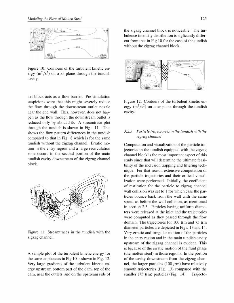
nel block acts as a flow barrier. Pre-simulationsuspicions were that this might severely reducethe flow through the downstream outlet nozzlenear the end wall. This, however, does not hap-pen as the flow through the downstream outlet isreduced only by about 5%. A streamtrace plotthrough the tundish is shown in Fig. 11. Thisshows the flow pattern differences in the tundishcompared to that in Fig. 8 which is for the sametundish without the zigzag channel. Erratic mo-tion in the entry region and a large recirculationzone occurs in the second portion of the maintundish cavity downstream of the zigzag channelblock.
Figure 11: Streamtraces in the tundish with thezigzag channel.
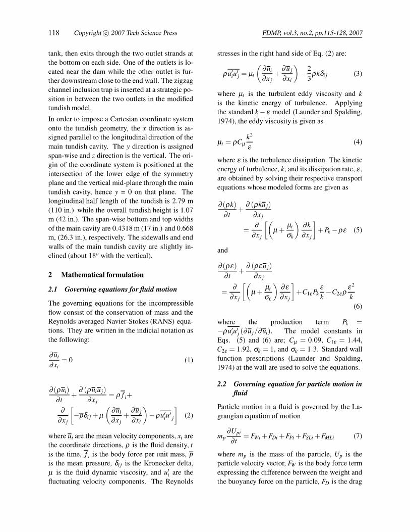
A sample plot of the turbulent kinetic energy forthe same xz plane as in Fig 10 is shown in Fig. 12.Very large gradients of the turbulent kinetic en-ergy upstream bottom part of the dam, top of thedam, near the outlets, and on the upstream side of
the zigzag channel block is noticeable. The tur-bulence intensity distribution is sigficantly differ-ent from that in Fig 10 for the case of the tundishwithout the zigzag channel block.
Figure 12: Contours of the turbulent kinetic en-ergy (m2/s2) on a xz plane through the tundishcavity.
3.2.3 Particle trajectories in the tundish with thezigzag channel
Computation and visualization of the particle tra-jectories in the tundish equipped with the zigzagchannel block is the most important aspect of thisstudy since that will determine the ultimate feasi-bility of the inclusion trapping and filtering tech-nique. For that reason extensive computation ofthe particle trajectories and their critical visual-ization were performed. Initially, the coefficientof restitution for the particle to zigzag channelwall collision was set to 1 for which case the par-ticles bounce back from the wall with the samespeed as before the wall collision, as mentionedin section 2.3. Particles having uniform diame-ters were released at the inlet and the trajectorieswere computed as they passed through the flowdomain. The trajectories for 100 μm and 75 μmdiameter particles are depicted in Figs. 13 and 14.Very erratic and irregular motion of the particlesin the entry region and in the main tundish cavityupstream of the zigzag channel is evident. Thisis because of the erratic motion of the fluid phase(the molten steel) in those regions. In the portionof the cavity downstream from the zigzag chan-nel, the larger particles (100 μm) have relativelysmooth trajectories (Fig. 13) compared with thesmaller (75 μm) particles (Fig. 14). Trajecto-

126 Copyright c© 2007 Tech Science Press FDMP, vol.3, no.2, pp.115-128, 2007
Figure 13: Trajectories of 100 μm diameter parti-cles when the coefficient restitution for wall colli-sion is set to 1.
Figure 14: Trajectories of 75 μm diameter parti-cles when the coefficient restitution for wall colli-sion is set to 1.
ries for a distribution of particles of various diam-eters (1-100 μm) released at the inlet are shownin Fig. 15. It has the same general trend as Figs.13 and 14. The same situations are repeated withthe coefficient of restitution for the particles to thezigzag channel wall collision set equal to zero.This mimics total particle adsorption at the wallin an ad-hoc manner. The particle trajectories forthis case are shown in Fig. 16. It can be seenthat none of the particles pass through the zigzagchannel block into the downstream portion of thecavity. This is quite remarkable in the sense that itdemonstrates, albeit in a simulated fashion, the ef-fectiveness of the zigzag channel surface in trap-ping the inclusion particles. It is thus expectedthat the proposed filtering technique has the po-tential to be successful. It will depend on the cap-ture efficiency of the zigzag channel trap.
The next step in this research is to actually fab-
Figure 15: Trajectories of 1-100 μm diameter par-ticles when the coefficient restitution for wall col-lision is set to 1.
Figure 16: Trajectories of 1-100 μm diameter par-ticles when the coefficient restitution for wall col-lision is set to 0.
ricate the zigzag channel block and install it inan existing tundish and conduct field trials. Thisphase is currently underway. It is anticipated thatbecause of the adhesion of the inclusion particlesto the zigzag channel surfaces, the channels willbecome somewhat clogged and the channel blockwill have to be replaced periodically. The timewhen the channels will be clogged beyond theirusable condition and how frequently they have tobe replaced will depend on the capture rate of theinclusions by the zigzag channel trap. It will notbe known until the field trials are conducted. Fur-ther optimization of the channel block design maybe required based on the field trial results. The re-sults of the field testing and subsequent channeldesign optimization will be reported in a subse-quent paper.

Modeling the Flow of Molten Steel 127
4 Summary and Conclusions
A physical-chemical filtering system for the re-moval of inclusion particles from molten steelin the tundish has been proposed. The moltensteel will be directed through zigzag channelsin the tundish furniture. The inclusion particlesare expected to come in contact with the zigzagchannel surfaces while passing through them be-cause of the increased recirculation and turbu-lence. The inclusion particles are expected tostick to the zigzag channel surfaces and bond andget trapped there. The feasibility of the filter-ing system has been evaluated numerically andthe results are reported in this study. The flowfield in the tundish was computed by solving theincompressible RANS equations employing thestandard k−ε turbulence model. The particle tra-jectories were computed by solving a Lagrangianparticle dynamics equation where the particles aresubjected to various physical and hydrodynamicforces. The trajectories are then visualized andcritically examined to assess the effectiveness ofthe proposed filtering system.
Design optimization of the zigzag channel wasperformed by first computing the flow through atwo dimensional zigzag channel and then comput-ing the particle trajectories through the channels.A channel with 60o zigzag angle and 0.0254 m(1 in) channel spacing was deemed satisfactoryfor the purpose. A channel block consisting ofthe same channel design was then inserted into athree-dimensional model of an existing continu-ous casting tundish. The hydrodynamic field andthe particles trajectories in the modified tundishmodel were then calculated and examined. It isconcluded that the proposed filtering techniquewill be very effective in removing the inclusionparticles in the tundish. The actual physical veri-fication of the effectiveness of the filtering systemwill be pursued in field tests shortly in the Timkenplant.
Acknowledgement: This work is fundedthrough the American Iron and Steel Institute’sTechnology Roadmap Program for the SteelIndustry (AISI - TRP Project No. 9757). Thesponsors are Timken Company and the US
Department of Energy (DE-FC36-97ID13554).
References
Abhilash, E.; Joseph, M.A.; Krishna, P. (2006):Prediction of dendritic parameters and macrohardness variation in permanent mould casting ofAl-12%Si alloys using artificial neural networks.Fluid Dynamics & Materials Processing, vol. 2,pp. 211-220.
Amberg, G.; Shiomi, J. (2005): Thermocapil-lary flow and phase change in some wide spreadmaterials processes. Fluid Dynamics & MaterialsProcessing, vol. 1, pp. 81-95.
Chakraborty, S.; Sahai, Y. (1991): Effect ofvarying ladle stream temperature on the melt flowand heat transfer in continuous casting tundishes.ISIJ International, vol. 31, pp. 960-967.
Chevrier, V.F. (2000): Droplet and bubble sepa-ration at the interface between a liquid metal anda liquid slag. Ph.D dissertation, Carnegie MellonUniversity.
Clift, R.; Grace, J.R.; Weber, M.E. (2005):Bubbles, Drops, and Particles. Dover Publica-tions.
Dash, K.S.; Jha, K.P. (2002): Effect of outlet po-sitions and various turbulence models on mixingin a single and multi-strand tundish. InternationalJournal of Numerical Methods for Heat and FluidFlow, vol. 12, pp. 560-584.
Dash, K.S.; Jha, K.P. (2004): Employment ofdifferent turbulence models to the design of opti-mum steel flows in a tundish. International Jour-nal of Numerical Methods for Heat and FluidFlow, vol. 14, pp. 953-979.
ESI-CFD (2006): CFD-ACE+T M Manual pub-lished by ESI-CFD, Inc.
He, Y.; Sahai, Y. (1990): Influence of some fac-tors on fluid flow in continuous casting tundishes.Acta Metallurgica Sinica. B, vol.3. pp. 49-53.
Hong, C.P.; Zhu, M.F.; Lee, S.Y. (2006): Mod-eling of dendritic growth in alloy solidificationwith melt convection. Fluid Dynamics & Mate-rials Processing, vol. 2, pp. 247-260.
Ichibashi, H. (1986): Application of filter for theclean steel. Proceedings of the Fifth International
128 Copyright c© 2007 Tech Science Press FDMP, vol.3, no.2, pp.115-128, 2007
Iron and Steel Congress, Tundish Metallurgy, vol.1, pp. 677-687
Ilegbusi, O.J.; Szekely, J. (1987): The model-ing of fluid flow, tracer dispersion and inclusionbehavior in tundishes. Mathematical Modelingof Materials Processing Operations, Szekely, J.,eds., TMS, Warrendale, PA, pp. 409-429.
Itoh, H.; Hino, M.; Ban-ya, S. (1997): Thermo-dynamics on the formation of spinel nonmetallicinclusion in liquid steel. Metallurgical and Mate-rial Transaction B - Process Metallurgy and Ma-terials Processing Science, vol. 28, pp. 953-956.
Javurak, M.; Kaufmann, B.; Gerhard, Z.;Philipp, G. (2002): Inclusion separation intundishes - some new general aspects. Steel Re-search, vol. 73, pp. 1-7.
Launder, B.E.; Spalding, D.B. (1974): The nu-merical computation of turbulent flows. Compu-tational Methods for Applied Mechanics and En-gineering, vol. 3, pp. 269-289.
Lopez-Ramirez, S.; Morales, R.D.; Serrano,J.A.R. (2000): Numerical simulation of the ef-fects of buoyancy forces and flow control deviceson fluid flow and heat transfer phenomena of liq-uid steel in a tundish. Numerical Heat TransferPart A – Applications, vol. 37, pp. 69-86.
Ludwig, A.; Gruber-Pretzler, M.; Wu, M.;Kuhn, A. Riedle, J. (2005): About the forma-tion of macrosegregations during continuous cast-ing of Sn-Bronze. Fluid Dynamics & MaterialsProcessing, vol. 1, pp. 285-300.
Lun, C.K.K.; Liu H.S.,(1997): Numerical sim-ulation of dilute turbulent gas-solid flows in hor-izontal channels. International Journal of Multi-phase Flow, vol. 23, pp. 575-605.
Narski J. and Picasso M., (2007): Adaptive 3Dfinite elements with high aspect ratio for dendriticgrowth of a binary alloy including fluid flow in-duced by shrinkage, FDMP: Fluid Dynamics &Materials Processing, Vol. 3, No. 1, pp. 49-64
Patankar, S.V. (1980): Numerical Heat Transferand Fluid Flow. Hemisphere, New York.
Ran, J.; Zhang, L.; Tang, Q.; Xin, M. (2006):Numerical simulation of the particle motion char-acteristics in boundary layer gas solid rotary flow.
Journal of Fluids Engineering, vol. 128, pp. 596-601.
Saffman, P.G. (1965): The lift on a small spherein a slow shear flow. Journal of Fluid Mechan-ics, vol. 22, pp. 385-400. Corrigendum (1968).Journal of Fluid Mechanics, vol. 31, pp. 624.
Schwarze, R.; Bbermeier, F.; Janke, D. (2001):Numerical simulation of fluid flow and dispersephase behavior in continuous casting tundishes.Modeling and Simulation in Material Science andEngineering, vol. 9, pp. 297-287.
Shen, F.; Khodadadi, J.M.; Pien, S.J.; Lan,X.K. (1994): Mathematical and Physical model-ing studies of molten aluminum flow in a tundish.Metallurgical and Materials Transaction B - Pro-cess Metallurgy and Materials Processing Sci-ence, vol. 25, pp. 669-680.
Sheng, D.Y.; Jonsson, L. (1999): Investigationof transient fluid flow and heat transfer in a con-tinuos casting tundish by numerical anlysis veri-fied with nonisothermal water model experiments.Metallurgical and Materials Transaction B - Pro-cess Metallurgy and Materials Processing Sci-ence, vol. 30, pp. 979-985.
Taniguchi, S.; Brimacombe, J.K. (1997): Appli-cation of pinch force to the separation of inclusionparticles from liquid steel. ISIJ International, vol.34, pp. 722 -731.
Vargas-Zamora, A.; Morales, R.D.; Diaz-Cruz, M.; Palafox-Ramos, J.; Demedices, L.G.(2003): Heat and mass transfer of a convective-stratified flow in a trough type tundish. Interna-tional Journal of Heat and Mass Transfer, vol. 46,pp. 3029-3039.
Yamada, W.; Kiyose, A.; Fukuda, J.; Tanaka,H.; Nakashima, J.I.. (2003): Simulation of co-agulation of noon metallic inclusions in tundishand their trappings into the solidified shells incontinuous casting mould. Iron Making and Steel-making, vol. 30, pp. 151-157.