Embed Size (px)
Citation preview
© 2006 The MathWorks, Inc.
Modeling Systems with Subsystems
Simulink® for System and Algorithm Modeling
7 - 2Modeling Systems with Subsystems
© 2006 The MathWorks, Inc.
Outline
• Introducing subsystems
• Creating a subsystem
• Combining subsystems into models
• Defining model callbacks
• Virtual versus nonvirtual subsystems
• Viewing the block sorted order
• Reviewing zero-crossings
• Modeling signal-driven subsystems
• Triggered and enabled subsystems
7 - 3Modeling Systems with Subsystems
© 2006 The MathWorks, Inc.
Introducing Subsystems
• To complete the controller and plant models for the electronic control system, create subsystems from the individual components and combine them into complete systems.
• Using subsystems has these advantages:
• It helps reduce the number of blocks displayed in your
model window.
• It allows you to keep functionally related blocks
together.
• It enables you to establish a hierarchical block
diagram, where a Subsystem block is on one layer
and the blocks that make up the subsystem are on
another.
7 - 4Modeling Systems with Subsystems
© 2006 The MathWorks, Inc.
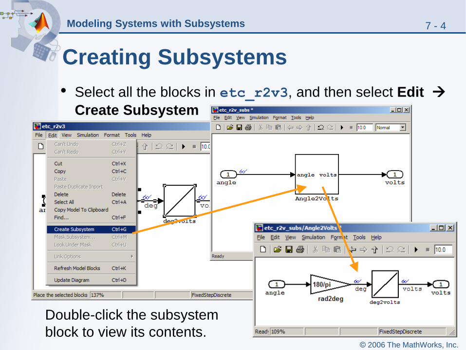
Creating Subsystems
• Select all the blocks in etc_r2v3, and then select Edit
Create Subsystem
Double-click the subsystem
block to view its contents.
7 - 5Modeling Systems with Subsystems
© 2006 The MathWorks, Inc.
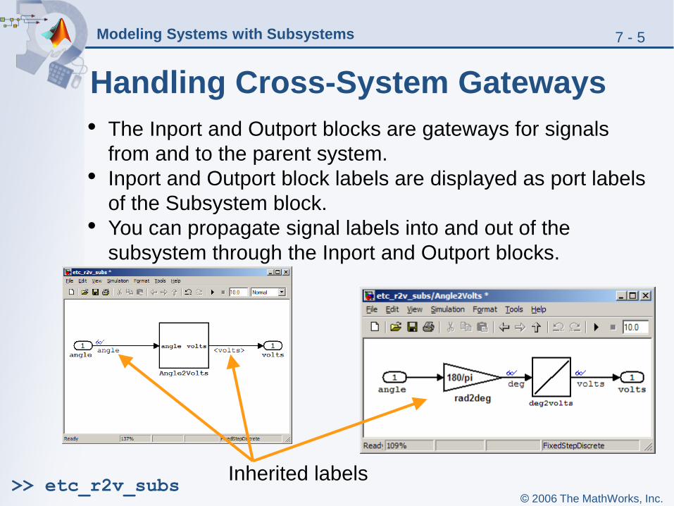
Handling Cross-System Gateways
• The Inport and Outport blocks are gateways for signals
from and to the parent system.
• Inport and Outport block labels are displayed as port labels
of the Subsystem block.
• You can propagate signal labels into and out of the
subsystem through the Inport and Outport blocks.
Inherited labels>> etc_r2v_subs
7 - 6Modeling Systems with Subsystems
© 2006 The MathWorks, Inc.
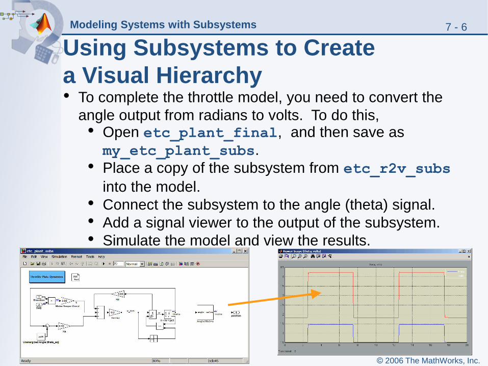
Using Subsystems to Create
a Visual Hierarchy• To complete the throttle model, you need to convert the
angle output from radians to volts. To do this,• Open etc_plant_final, and then save as
my_etc_plant_subs.
• Place a copy of the subsystem from etc_r2v_subs
into the model.
• Connect the subsystem to the angle (theta) signal.
• Add a signal viewer to the output of the subsystem.
• Simulate the model and view the results.

7 - 7Modeling Systems with Subsystems
© 2006 The MathWorks, Inc.
Defining the Model Callbacks
• Open model properties dialog by selecting File > Model Properties.
• Enter expressions that initialize workspace parameters using the Model initialization function field in the Callbacks tab.
7 - 8Modeling Systems with Subsystems
© 2006 The MathWorks, Inc.
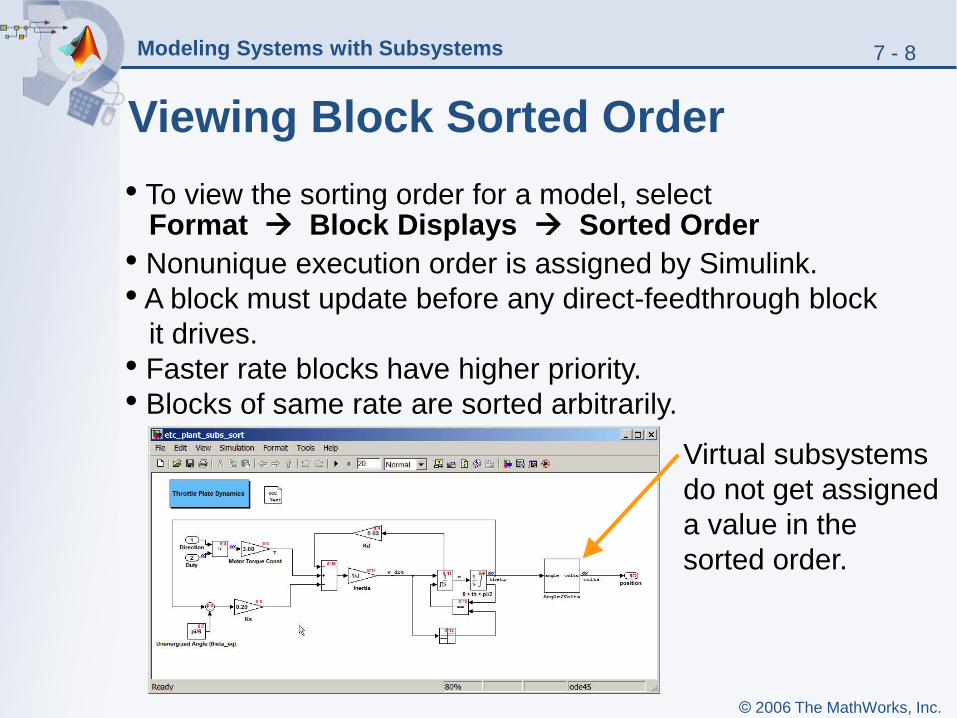
Viewing Block Sorted Order
• To view the sorting order for a model, select Format Block Displays Sorted Order
• Nonunique execution order is assigned by Simulink.
• A block must update before any direct-feedthrough block
it drives.
• Faster rate blocks have higher priority.
• Blocks of same rate are sorted arbitrarily.
Virtual subsystems
do not get assigned
a value in the
sorted order.
7 - 9Modeling Systems with Subsystems
© 2006 The MathWorks, Inc.
Reviewing Zero Crossings
• Simulink uses a technique known as zero-crossing detection to accurately locate discontinuities.
• With variable-step solvers, Simulink interpolates to estimate times of zero crossings.
• A zero crossing occurs when
• A signal changes its sign.
• A block changes its operating mode.
7 - 10Modeling Systems with Subsystems
© 2006 The MathWorks, Inc.
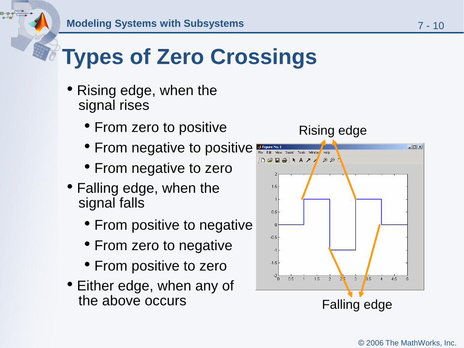
Types of Zero Crossings
Rising edge
Falling edge
• Rising edge, when the signal rises
• From zero to positive
• From negative to positive
• From negative to zero
• Falling edge, when the signal falls
• From positive to negative
• From zero to negative
• From positive to zero
• Either edge, when any of the above occurs
7 - 11Modeling Systems with Subsystems
© 2006 The MathWorks, Inc.
Modeling Signal-Driven Systems
• Conditionally executed subsystems are signal-driven systems.
• Execution of a conditionally executed subsystem depends on a control signal in one of two ways:
• Sign of the control signal
• Zero crossing in the control signal
• There are two types of conditionally executed subsystems:
• Enabled subsystems execute if the control signal is positive.
• Triggered subsystems execute once if the control signal crosses zero in a specific direction.
• Conditionally executed subsystems are nonvirtual.

7 - 12Modeling Systems with Subsystems
© 2006 The MathWorks, Inc.
Virtual Versus Nonvirtual Subsystems
Subsystems
Virtual(visual hierarchy)
Nonvirtual(treat as single unit)
Atomic(treat as single unit)
Conditionally Executed(execution based on a control
or trigger signal)
Enabled Triggered
7 - 13Modeling Systems with Subsystems
© 2006 The MathWorks, Inc.
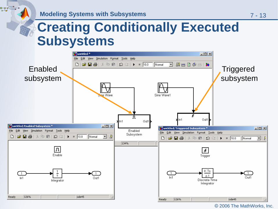
Creating Conditionally Executed Subsystems
Enabled
subsystem
Triggered
subsystem
7 - 14Modeling Systems with Subsystems
© 2006 The MathWorks, Inc.
Introducing Triggered Subsystems
• A triggered subsystem executes once when its control signal (trigger signal) crosses zero in the direction that matches its setting.
• Outputs of a triggered subsystem are always held between two subsequent triggers.
• Triggered subsystems cannot contain continuous blocks.
• Triggered subsystems can contain discrete blocks with an inherited sample time.

7 - 15Modeling Systems with Subsystems
© 2006 The MathWorks, Inc.
Introducing Enabled Subsystems
• An enabled subsystem is active as long as its control signal (enabled signal) is positive.
• Outputs of an enabled subsystem can either be held or reset when it becomes inactive. You set this option from the block parameters dialog of the subsystem-level Outport blocks.
• States in an enabled subsystem can either be held or reset when it reactivates. You set this option from the parameters dialog box of the Enable block.
7 - 16Modeling Systems with Subsystems
© 2006 The MathWorks, Inc.
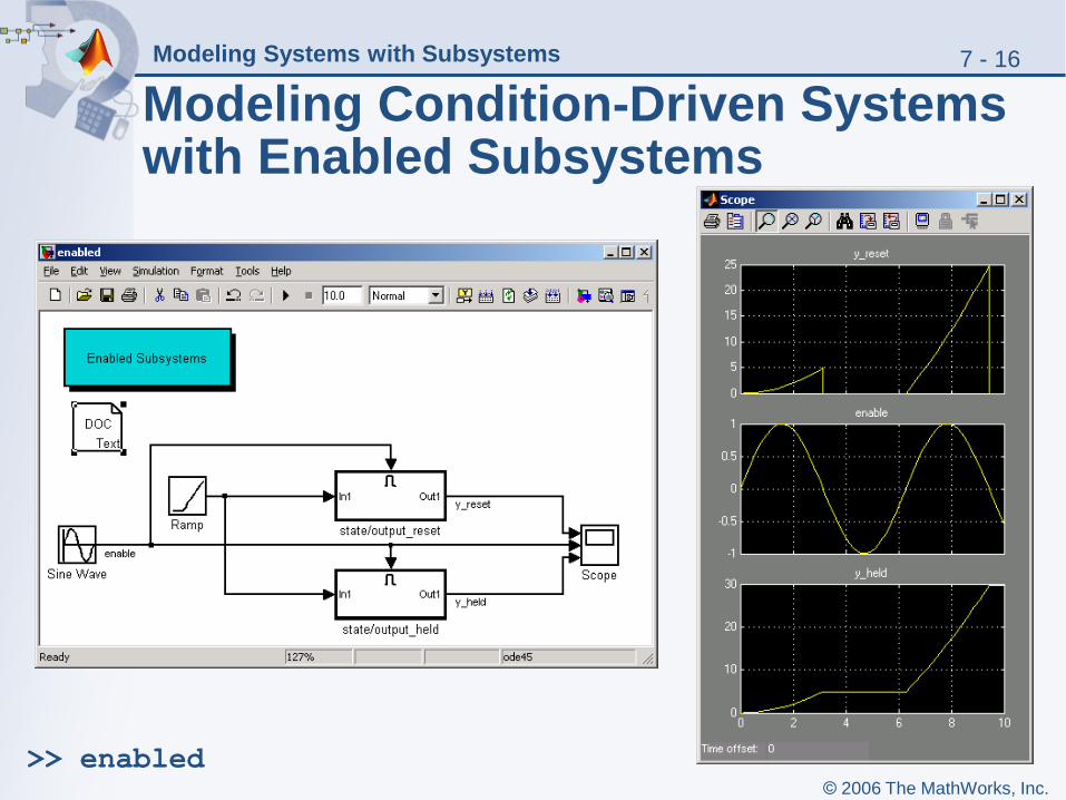
Modeling Condition-Driven Systems with Enabled Subsystems
>> enabled
7 - 17Modeling Systems with Subsystems
© 2006 The MathWorks, Inc.
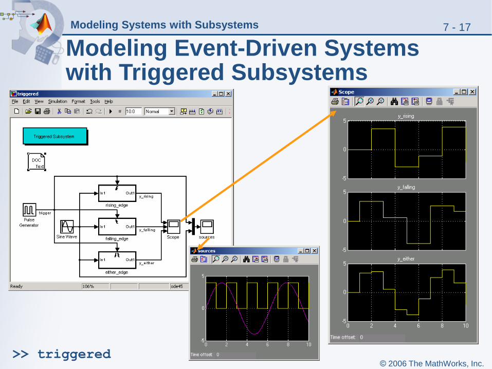
Modeling Event-Driven Systems with Triggered Subsystems
>> triggered

7 - 18Modeling Systems with Subsystems
© 2006 The MathWorks, Inc.
Example: Four-Cylinder, Four-Stroke Internal Combustion Engine
>> four_cylinder_engine
• Select Format Port/Signal Displays Sample Time Colors to view the different rates in the model.
• What does each color correspond to?
7 - 19Modeling Systems with Subsystems
© 2006 The MathWorks, Inc.
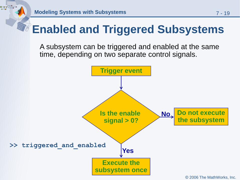
Enabled and Triggered Subsystems
Trigger event
Do not execute the subsystem
Is the enable signal > 0?
Execute the subsystem once
No
Yes
A subsystem can be triggered and enabled at the same time, depending on two separate control signals.
>> triggered_and_enabled
7 - 20Modeling Systems with Subsystems
© 2006 The MathWorks, Inc.
Summary
• Introducing subsystems
• Creating a subsystem
• Combining subsystems into models
• Defining model callbacks
• Virtual versus nonvirtual subsystems
• Viewing the block sorted order
• Reviewing zero-crossings
• Modeling signal-driven subsystems
• Triggered and enabled subsystems