Embed Size (px)
Citation preview

Modeling Reliability of Ceramics Under Transient Loads and Temperatures
Noel N. Nemeth
Osama M. Jadaan
Eric H. Baker
The 26th Annual International Conference on Advanced Ceramics & Composites
January 13-18, 2002,
Cocoa Beach Florida
Glenn Research Centerat Lewis Field
E-mail: [email protected]
Life Prediction Branch
Outline Objective Background - CARES/Life
- References to previous work
Theory - Power law & Walker law
- Computationally efficient method for cyclic loading
Examples - Diesel exhaust valve
- Alumina static fatigue
Conclusions

Objective
Develop a methodology to predict the time-dependent reliability (probability of survival) of brittle material components subjected to transient thermomechanical loading, taking into account the change in material response with time.
Transient reliability analysis
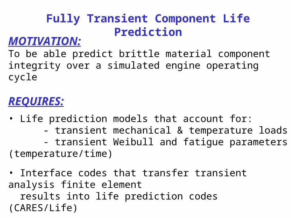
Fully Transient Component Life Prediction
MOTIVATION: To be able predict brittle material component integrity over a simulated engine operating cycle
REQUIRES:
• Life prediction models that account for: - transient mechanical & temperature loads - transient Weibull and fatigue parameters (temperature/time)
• Interface codes that transfer transient analysis finite element results into life prediction codes (CARES/Life)

CARES/Life (Ceramics Analysis and Reliability Evaluation of Structures)
Software For Designing With Brittle Material Structures
CARES/Life – Predicts the instantaneous and time-dependent probability of failure of advanced ceramic components under thermomechanical loading
Couples to ANSYS, ABAQUS, MARC, NASTRAN
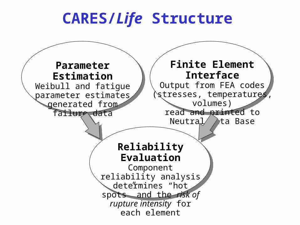
CARES/Life Structure
Reliability EvaluationComponent reliability analysis determines “hot spots” and the
risk of rupture intensity for each element
Parameter EstimationWeibull and fatigue parameter
estimates generated fromfailure data
Finite Element InterfaceOutput from FEA codes
(stresses, temperatures, volumes)read and printed toNeutral Data Base
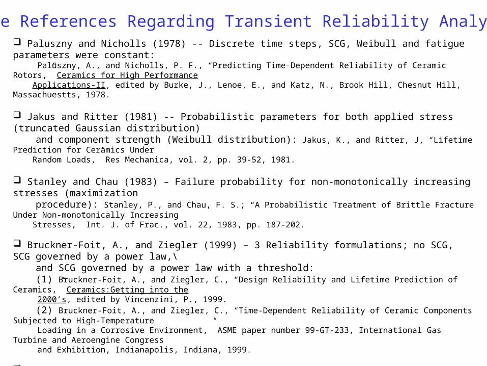
Paluszny and Nicholls (1978) -- Discrete time steps, SCG, Weibull and fatigue parameters were constant: Paluszny, A., and Nicholls, P. F., “Predicting Time-Dependent Reliability of Ceramic Rotors,” Ceramics for High Performance Applications-II, edited by Burke, J., Lenoe, E., and Katz, N., Brook Hill, Chesnut Hill, Massachuestts, 1978.
Jakus and Ritter (1981) -- Probabilistic parameters for both applied stress (truncated Gaussian distribution) and component strength (Weibull distribution): Jakus, K., and Ritter, J, “Lifetime Prediction for Ceramics Under Random Loads,” Res Mechanica, vol. 2, pp. 39-52, 1981.
Stanley and Chau (1983) – Failure probability for non-monotonically increasing stresses (maximization procedure): Stanley, P., and Chau, F. S.; “A Probabilistic Treatment of Brittle Fracture Under Non-monotonically Increasing Stresses,” Int. J. of Frac., vol. 22, 1983, pp. 187-202.
Bruckner-Foit, A., and Ziegler (1999) – 3 Reliability formulations; no SCG, SCG governed by a power law,\ and SCG governed by a power law with a threshold: (1) Bruckner-Foit, A., and Ziegler, C., “Design Reliability and Lifetime Prediction of Ceramics,” Ceramics:Getting into the 2000’s, edited by Vincenzini, P., 1999. (2) Bruckner-Foit, A., and Ziegler, C., “Time-Dependent Reliability of Ceramic Components Subjected to High-Temperature Loading in a Corrosive Environment,” ASME paper number 99-GT-233, International Gas Turbine and Aeroengine Congress and Exhibition, Indianapolis, Indiana, 1999.
Ziegler (1998) -- SCG parameters vary with temperature/time: Ziegler, C., Bewertung der Zuverlassigkeit Keramischer Komponenten bei zeitlich veranderlichen Spannungen und bei Hochtemperaturbelastung, Ph.D. Thesis, Karlsruhe University, 1998.
Jadaan and Nemeth (2001) – Cyclic loading + Weibull and SCG parameters vary with temperature/time: (1) Jadaan, O, and Nemeth, N. N.;”Transient Reliability of Ceramic Structures.” Fatigue & Frac. Of Eng. Mater. Struct., vol. 24, pp. 475-487. (2) Nemeth, N. N., and Jadaan, O.; “Transient Reliability of Ceramic Structures For Heat Engine Applications,” Proceedings of the 5th Annual FAA/Air Force/NASA/Navy Workshop on the Application of Probabilistic Methods to Gas Turbine Engines, June 11-14, 2001, Westlake Ohio.
Some References Regarding Transient Reliability Analysis
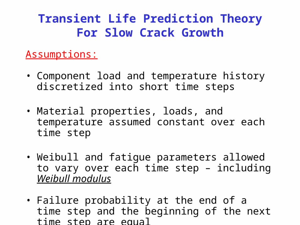
Transient Life Prediction TheoryFor Slow Crack Growth
Assumptions:
• Component load and temperature history discretized into short time steps
• Material properties, loads, and temperature assumed constant over each time step
• Weibull and fatigue parameters allowed to vary over each time step – including Weibull modulus
• Failure probability at the end of a time step and the beginning of the next time step are equal
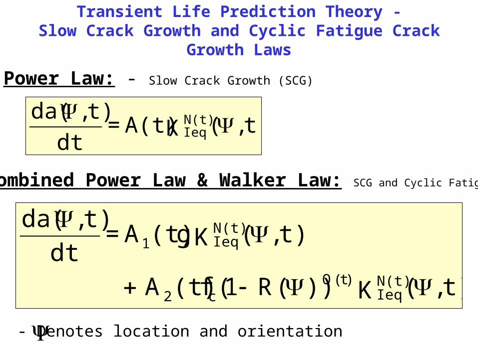
Transient Life Prediction Theory -Slow Crack Growth and Cyclic Fatigue Crack Growth Laws
Power Law: - Slow Crack Growth (SCG)
t),(K A(t) = dt
t),da( N(t)Ieq
Combined Power Law & Walker Law: SCG and Cyclic Fatigue
- Denotes location and orientation
t),(K ))(R1(f(t)A
t),(K g(t)A = dt
t),da(
N(t)Ieq
)t(Qc2
N(t)Ieq1
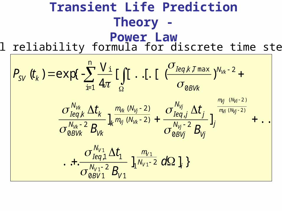
Transient Life Prediction Theory -Power Law
}]]...
....]]
)([[...[[4V{-exp)(
211
210
11,
20
,)2(
)2(
20
,
2
0
max,,in
1=i
1
1
1
1
)2(
)2(
iN
m
VNBV
NIeq
j
VjNBVj
jN
jIeqNm
Nm
kVk
NBVk
kN
kIeq
N
BVk
TkIeqkSV
dB
t
B
t
B
t
tP
V
V
V
V
VjNVim
ViNVjm
Vj
Vj
VkVj
VjVk
Vk
Vk
Vk
General reliability formula for discrete time steps:
33n22n1nnn yx
!3
2n1nnyx
!2
1nnynxxyx
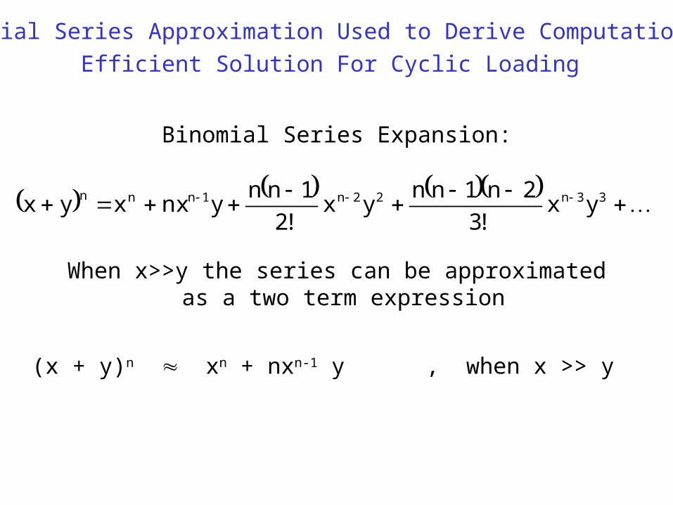
Binomial Series Expansion:
(x + y)n xn + nxn-1 y , when x >> y
When x>>y the series can be approximated as a two term expression
Binomial Series Approximation Used to Derive Computationally
Efficient Solution For Cyclic Loading
)21VN(km
)2kN(1Vm
1V
1V)2)1k(VN()2k(Vm
)2)2k(VN()1k(Vm
)1k(V
)1k(V)2VkN()1k(Vm
)2)1k(VN(Vkm
Vk
Vk
)21VN(km
)2kN(1Vm
1V
1V)2)1k(VN()2k(Vm
)2)2k(VN()1k(Vm
)1k(V
)1k(V)2VkN()1k(Vm
)2)1k(VN(Vkm
Vk
Vk
11V
2N1BV0
1nN
1,Ieq1k
)1k(V2N)1k(BV0
)1k(nN
)1k(,Ieqk
Vk2N
BVk0
knN
k,Ieq
11V
2N1BV0
12N
1,Ieq1k
)1k(V2N)1k(BV0
)1k(2N
)1k(,Ieqk
Vk2N
BVk0
k2N
k,Ieq
]B
tZ.......]
B
tZ]
B
tZ...
...]B
tZ.......]
B
tZ]
B
tZ
)21VN(km
)2kN(1Vm
1V
1V)2)1k(VN()2k(Vm
)2)2k(VN()1k(Vm
)1k(V
)1k(V)2VkN()1k(Vm
)2)1k(VN(Vkm
Vk
Vk
Vk
11V
2N1BV0
11N
1,Ieq1k
)1k(V2N)1k(BV0
)1k(1N
)1k(,Ieqk
Vk2N
BVk0
k1N
k,Ieq
2N
BVk0
maxT,k,Ieq1
]B
tZ.......]
B
tZ]
B
tZ
[[[...[[[...[[...[...X
}]d]X[[4V{-exp)t(P i21vN
1vm
11i
n
1=i
kSV
n
1i
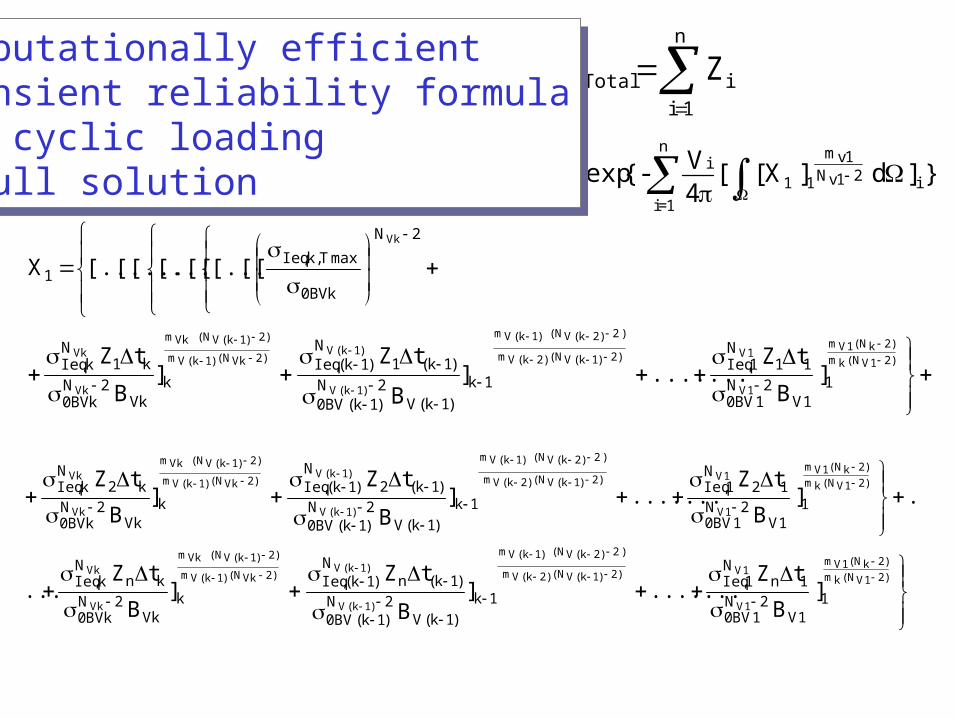
iTotal ZZComputationally efficient transient reliability formulafor cyclic loading- full solution
Computationally efficient transient reliability formulafor cyclic loading- full solution
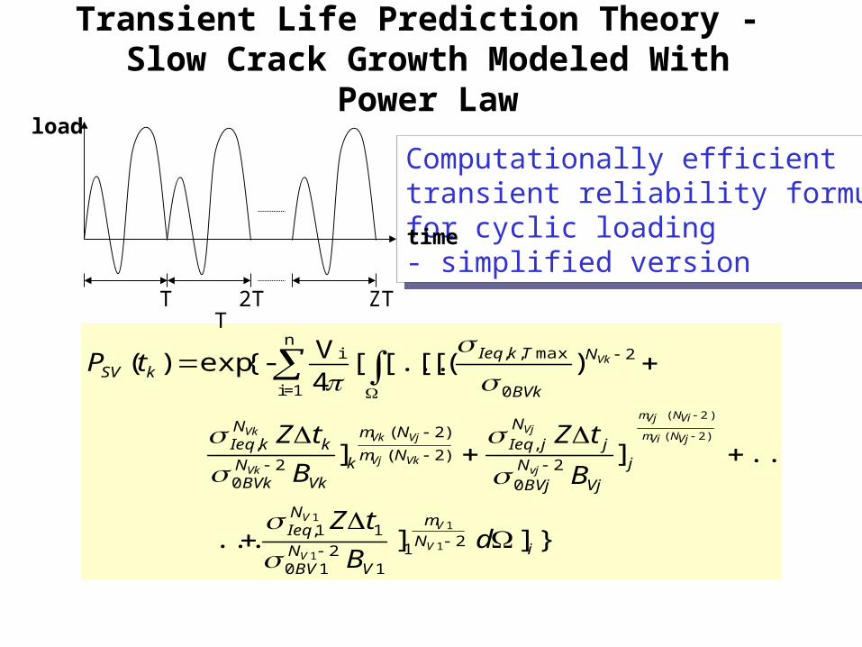
Transient Life Prediction Theory - Slow Crack Growth Modeled With Power Law
Computationally efficient transient reliability formulafor cyclic loading- simplified version
Computationally efficient transient reliability formulafor cyclic loading- simplified version
}]]...
....]]
)([[[...[4V{-exp)(
211
210
11,
20
,)2(
)2(
20
,
2
0
max,,in
1=i
1
1
1
1
)2(
)2(
iN
m
VNBV
NIeq
j
VjNBVj
jN
jIeqNm
Nm
kVk
NBVk
kN
kIeq
N
BVk
TkIeqkSV
dB
tZ
B
tZ
B
tZ
tP
V
V
V
V
VjNVim
ViNVjm
vj
Vj
VkVj
VjVk
Vk
Vk
Vk
TT
2T ZT
load
time
}]dB
tZ)R1(A
Af1
...
...B
tZ)R1(A
Af1
B
tZ)R1(A
Af1
[[...[4V{-exp)t(P
i
)2N(
m
1
1V2N
1BV0
1Q
1V1
2c
N
1,Ieq
T,1,IeqN1,Ieq
)2N(m
)2N(m
j
Vj
2N
BVj0
j
Q
Vj1
2c
N
j,Ieq
T,j,IeqN
j,Ieq
)2N(m
)2N(m
k
Vk2N
BVk0
kQ
Vk1
2c
N
k,Ieq
T,k,IeqNk,Ieq2N
BVk0
T,k,Ieq
in
1=ikSV
1V
1V
1V
1V
1V
Max1V
VjVi
ViVj
Vj
Vj
Vj
MaxVj
VkVj
VjVk
Vk
Vk
Vk
MaxVk
Vk
Max
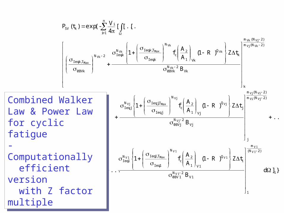
Combined Walker Law & Power Law for cyclic fatigue- Computationally efficient version with Z factor multiple
Combined Walker Law & Power Law for cyclic fatigue- Computationally efficient version with Z factor multiple
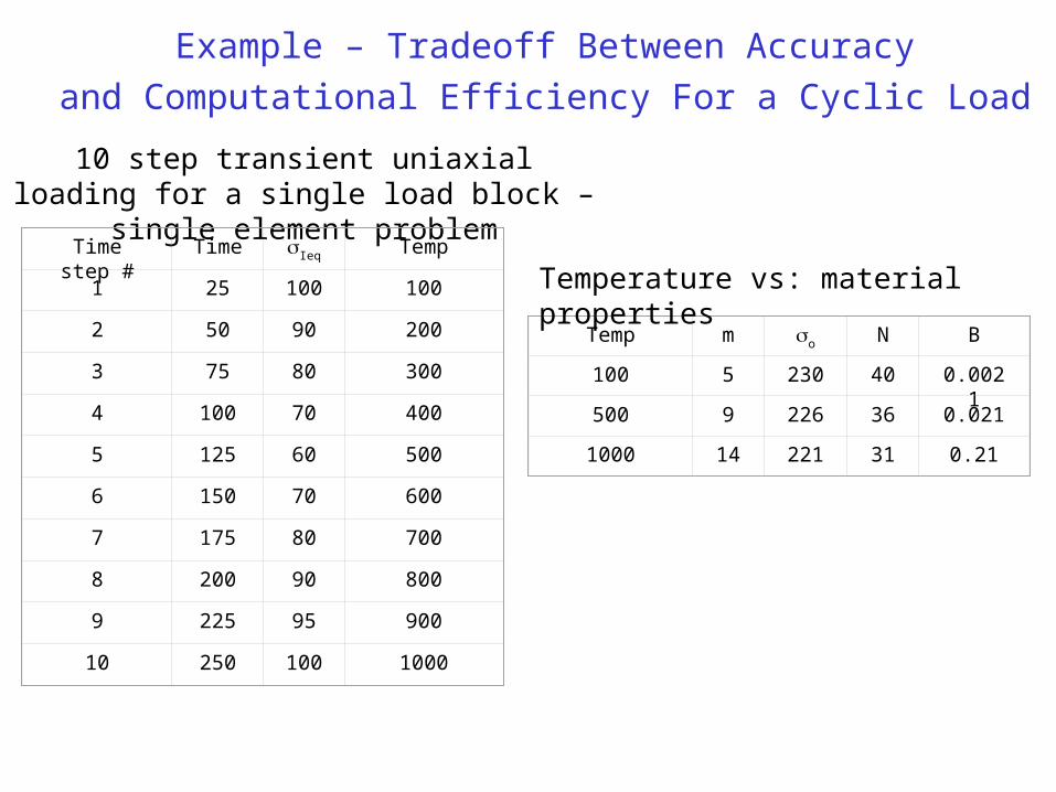
10 step transient uniaxial loading for a single load block – single element problem
Time step #
Time Ieq Temp
1 25 100 100
2 50 90 200
3 75 80 300
4 100 70 400
5 125 60 500
6 150 70 600
7 175 80 700
8 200 90 800
9 225 95 900
10 250 100 1000
Temp m o N B
100 5 230 40 0.0021
500 9 226 36 0.021
1000 14 221 31 0.21
Temperature vs: material properties
Example – Tradeoff Between Accuracy
and Computational Efficiency For a Cyclic Load
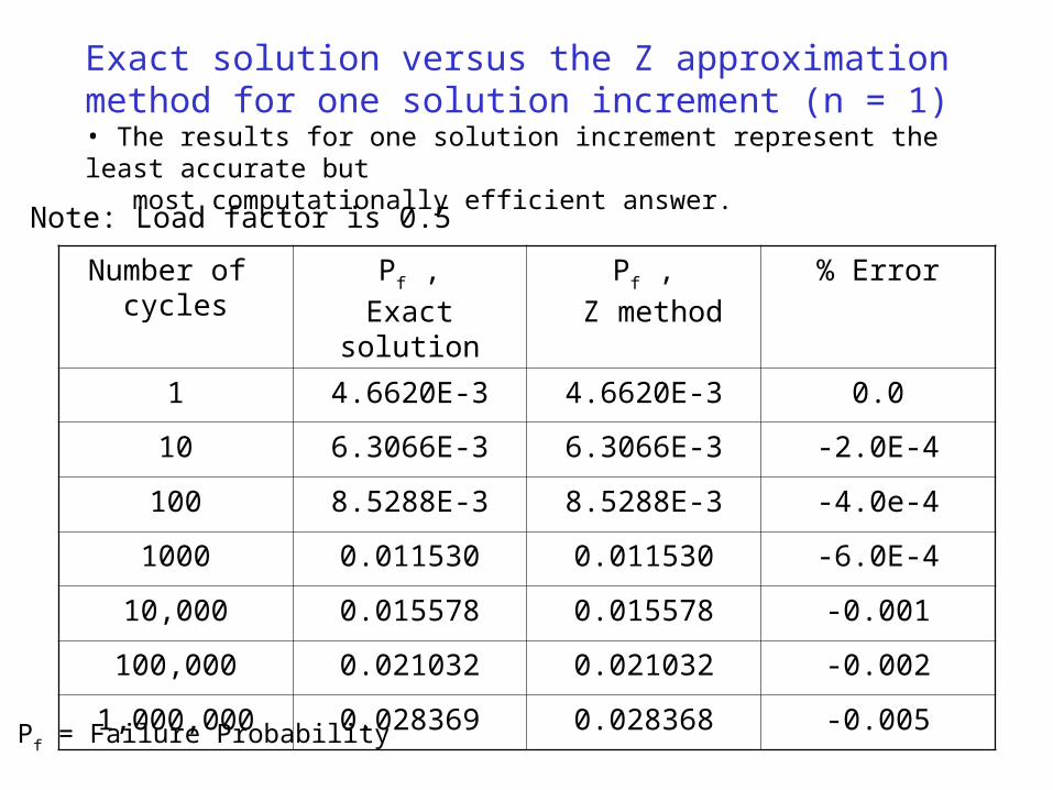
Exact solution versus the Z approximation method for one solution increment (n = 1)• The results for one solution increment represent the least accurate but most computationally efficient answer.
Number of cycles
Pf ,
Exact solution
Pf ,
Z method
% Error
1 4.6620E-3 4.6620E-3 0.0
10 6.3066E-3 6.3066E-3 -2.0E-4
100 8.5288E-3 8.5288E-3 -4.0e-4
1000 0.011530 0.011530 -6.0E-4
10,000 0.015578 0.015578 -0.001
100,000 0.021032 0.021032 -0.002
1,000,000 0.028369 0.028368 -0.005
Note: Load factor is 0.5
Pf = Failure Probability
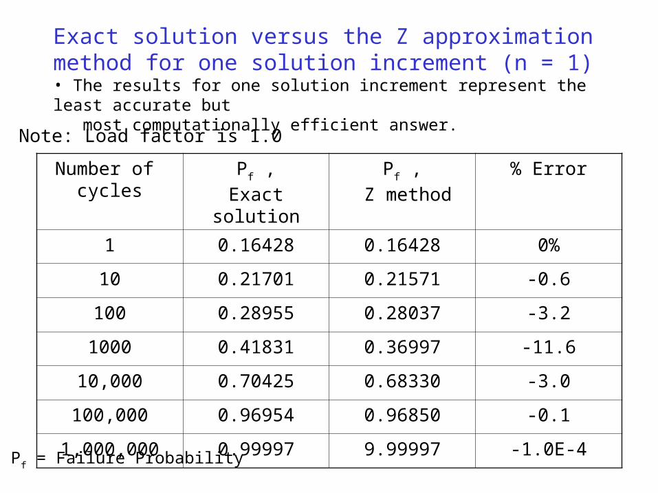
Exact solution versus the Z approximation method for one solution increment (n = 1)• The results for one solution increment represent the least accurate but most computationally efficient answer.
Number of cycles
Pf ,
Exact solution
Pf ,
Z method
% Error
1 0.16428 0.16428 0%
10 0.21701 0.21571 -0.6
100 0.28955 0.28037 -3.2
1000 0.41831 0.36997 -11.6
10,000 0.70425 0.68330 -3.0
100,000 0.96954 0.96850 -0.1
1,000,000 0.99997 9.99997 -1.0E-4
Note: Load factor is 1.0
Pf = Failure Probability
Cycles Pf
exact solution
Pf
n = 1
Pf
n = 2
Pf
n = 5
Pf
n = 10
Pf
n = 100
Pf
n = 500
Pf
n = 1000
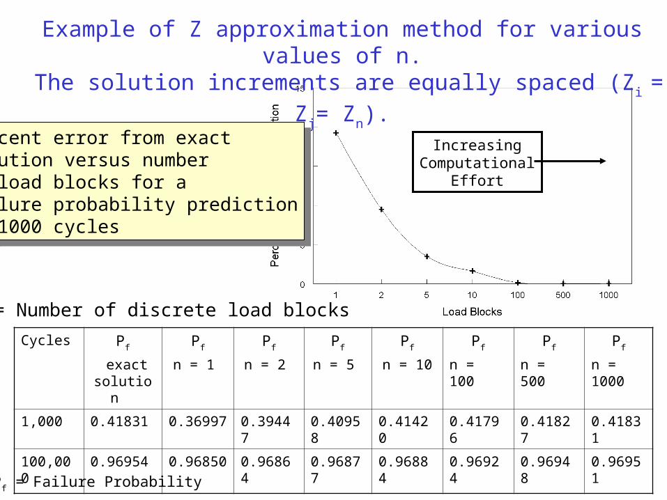
1,000 0.41831 0.36997 0.39447 0.40958 0.41420 0.41796 0.41827 0.41831
100,000 0.96954 0.96850 0.96864 0.96877 0.96884 0.96924 0.96948 0.96951
Example of Z approximation method for various values of n. The solution increments are equally spaced (Zi = Zj= Zn).
Percent error from exactsolution versus numberof load blocks for afailure probability predictionof 1000 cycles
Percent error from exactsolution versus numberof load blocks for afailure probability predictionof 1000 cycles
n = Number of discrete load blocks
IncreasingComputational
Effort
Pf = Failure Probability
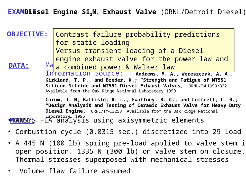
EXAMPLE: Diesel Engine Si3N4 Exhaust Valve (ORNL/Detroit Diesel)
DATA: Material: Silicon Nitride NT551Information Source: Andrews, M. A., Wereszczak, A. A., Kirkland, T. P., and Breder, K.; “Strength and Fatigue of NT551 Silicon Nitride and NT551 Diesel Exhaust Valves,” ORNL/TM1999/332. Available from the Oak Ridge National Laboratory 1999
Corum, J. M, Battiste, R. L., Gwaltney, R. C., and Luttrell, C. R.; “Design Analysis and Testing of Ceramic Exhaust Valve for Heavy Duty Diesel Engine,” ORNL/TM13253. Available from the Oak Ridge National Laboratory, 1996
MODEL: • ANSYS FEA analysis using axisymmetric elements
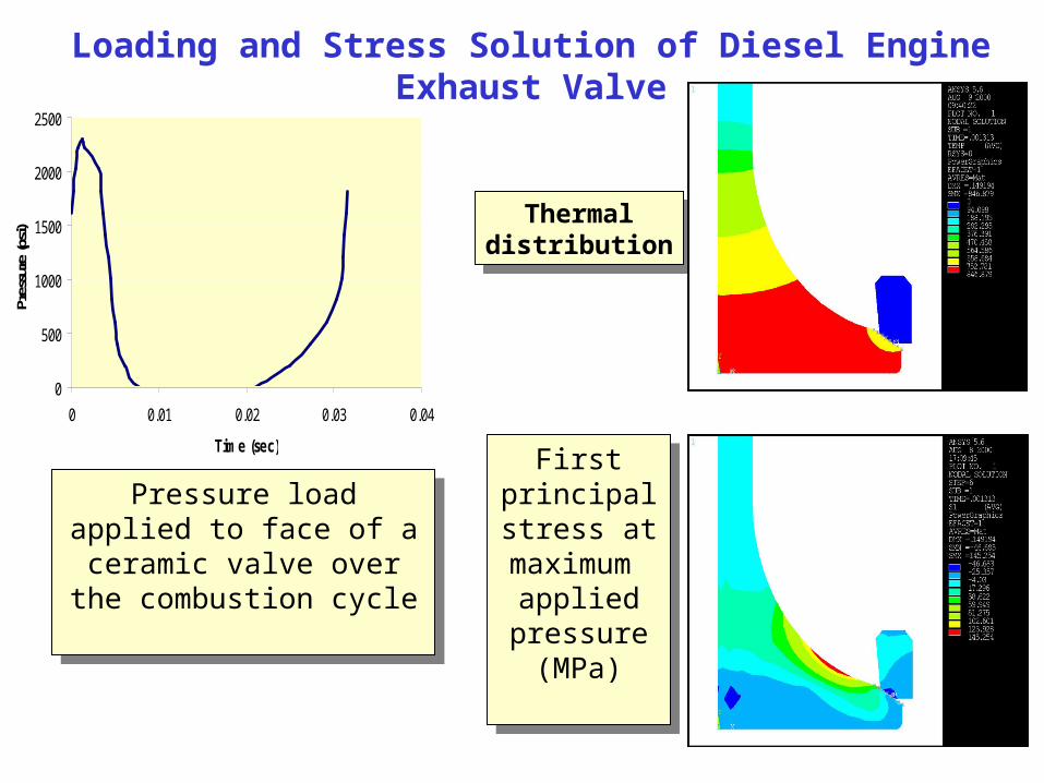
• Combustion cycle (0.0315 sec.) discretized into 29 load steps
• A 445 N (100 lb) spring pre-load applied to valve stem in open position. 1335 N (300 lb) on valve stem on closure. Thermal stresses superposed with mechanical stresses
• Volume flaw failure assumed
OBJECTIVE: Contrast failure probability predictions for static loadingVersus transient loading of a Diesel engine exhaust valve for the power law and a combined power & Walker law
0
500
1000
1500
2000
2500
0 0.01 0.02 0.03 0.04
Time (sec)
Pres
sure
(psi
)
Pressure load applied to face of a ceramic valve over
the combustion cycle
Pressure load applied to face of a ceramic valve over
the combustion cycle
Thermaldistribution
Thermaldistribution
First principalstress at maximum
applied pressure
(MPa)
First principalstress at maximum
applied pressure
(MPa)
Loading and Stress Solution of Diesel Engine Exhaust Valve
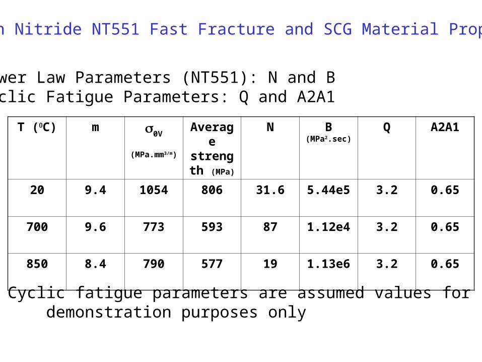
Silicon Nitride NT551 Fast Fracture and SCG Material Properties
T (C) m 0V
(MPa.mm3/m)
Average strength
(MPa)
N B(MPa2.sec)
Q A2A1
20 9.4 1054 806 31.6 5.44e5 3.2 0.65
700 9.6 773 593 87 1.12e4 3.2 0.65
850 8.4 790 577 19 1.13e6 3.2 0.65
Power Law Parameters (NT551): N and BCyclic Fatigue Parameters: Q and A2A1
Note: Cyclic fatigue parameters are assumed values for demonstration purposes only

Diesel Engine Si3N4 Exhaust Valve
Batdorf, SERR criterion with Griffith crack
Transient and static probability of failure versus combustion cycles(1000 hrs = 1.14E+8 cycles)
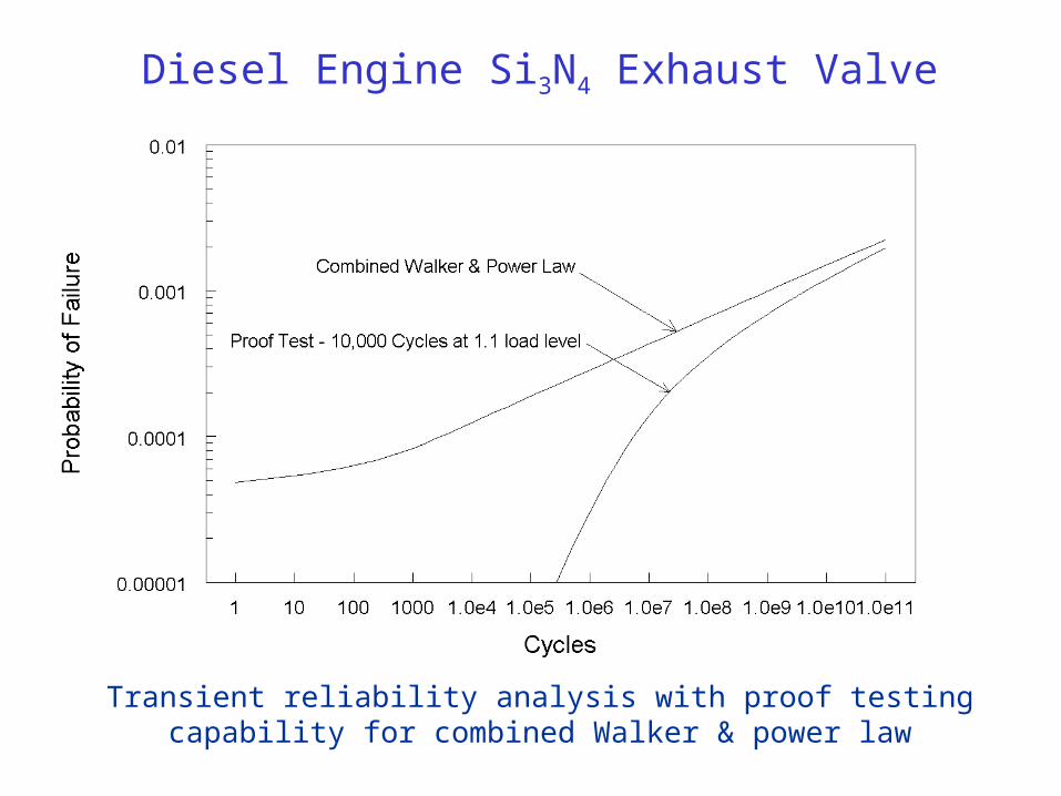
Diesel Engine Si3N4 Exhaust Valve
Transient reliability analysis with proof testing capability for combined Walker & power law
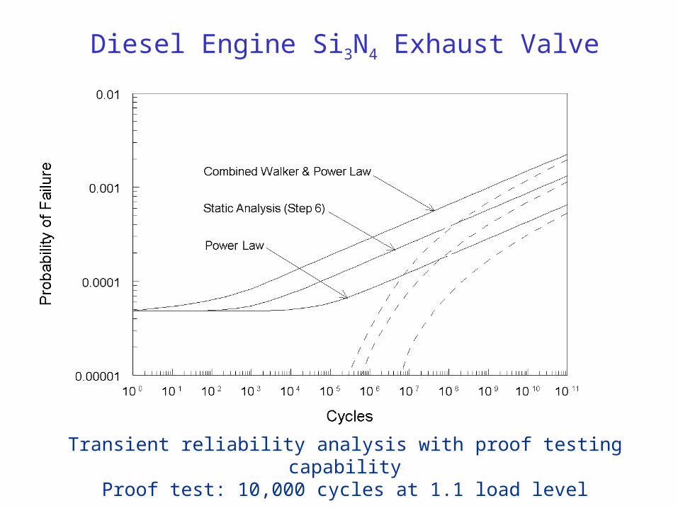
Diesel Engine Si3N4 Exhaust Valve
Transient reliability analysis with proof testing capabilityProof test: 10,000 cycles at 1.1 load level
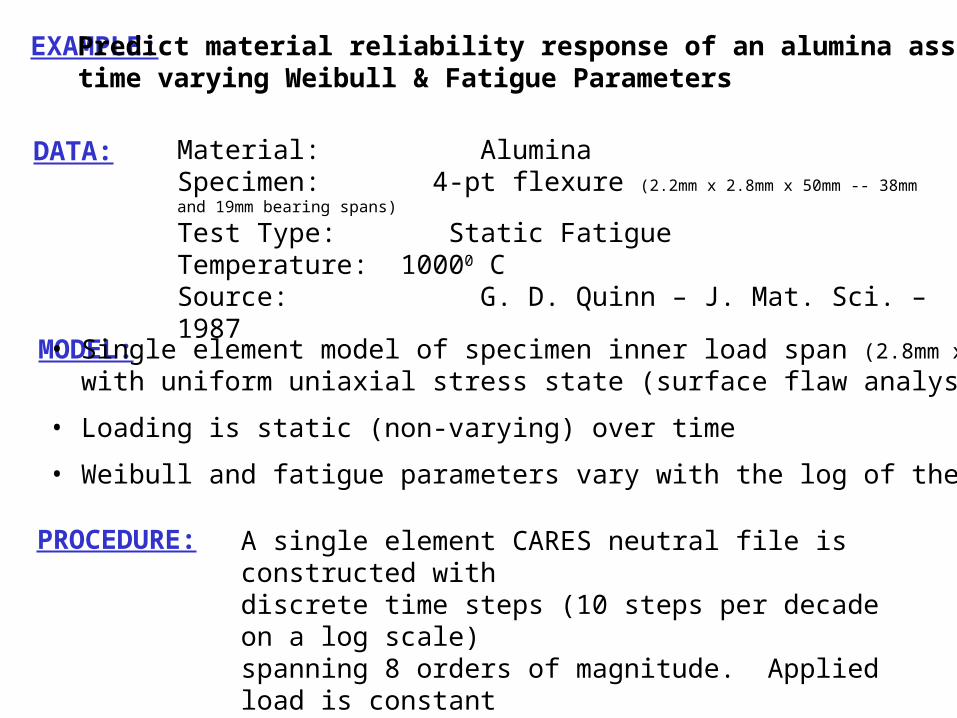
EXAMPLE: Predict material reliability response of an alumina assumingtime varying Weibull & Fatigue Parameters
DATA: Material: AluminaSpecimen: 4-pt flexure (2.2mm x 2.8mm x 50mm -- 38mm and 19mm bearing spans)
Test Type: Static FatigueTemperature: 10000 CSource: G. D. Quinn – J. Mat. Sci. – 1987
MODEL: • Single element model of specimen inner load span (2.8mm x 19mm)
with uniform uniaxial stress state (surface flaw analysis)
• Loading is static (non-varying) over time
• Weibull and fatigue parameters vary with the log of the time
PROCEDURE: A single element CARES neutral file is constructed withdiscrete time steps (10 steps per decade on a log scale)spanning 8 orders of magnitude. Applied load is constantbut Weibull and fatigue parameters allowed to vary with each time step.
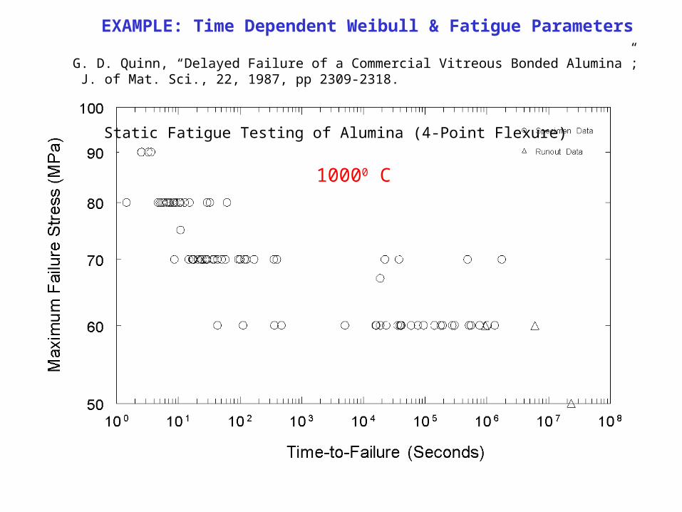
EXAMPLE: Time Dependent Weibull & Fatigue Parameters
G. D. Quinn, “Delayed Failure of a Commercial Vitreous Bonded Alumina”; J. of Mat. Sci., 22, 1987, pp 2309-2318.
Static Fatigue Testing of Alumina (4-Point Flexure)
10000 C
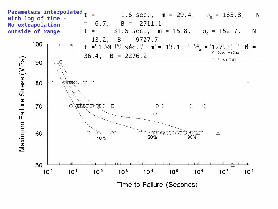
t = 1.6 sec., m = 29.4, 0= 165.8, N = 6.7, B = 2711.1
t = 31.6 sec., m = 15.8, 0= 152.7, N = 13.2, B = 9707.7
t = 1.0E+5 sec., m = 13.1, 0= 127.3, N = 36.4, B = 2276.2
Parameters interpolatedwith log of time -No extrapolationoutside of range

t = 1.6 sec., m = 29.4, 0= 165.8, N = 6.7, B = 2711.1
t = 31.6 sec., m = 7.4, 0= 263.3, N = 8.0, B = 2395.9
t = 316.2 sec., m = 4.5, 0= 870.1, N = 9.0, B = 10,389.0
Parameters interpolatedwith log of time -No extrapolationoutside of range
Conclusions
A computationally efficient methodology for computing the transient reliability in ceramic components subjected to cyclic thermomechanical loading was developed for power law (SCG), and combined power & Walker law (SCG & cyclic fatigue).
This methodology accounts for varying stresses as well as varying Weibull and fatigue parameters with time/temperature.
FORTRAN routines have been coded for the CARES/Life (version 6.0), and examples demonstrating the program viability & capability were presented.
Future Plans
Goal to release CARES/Life 6.0 to engine companies for evaluation/beta testing by 9/30/02
- Continuing benchmarking activities - Continue developing GUI - Complete ANSYS and ABAQUS interfaces - User guide with example problems ?? (FY’02 - FY’03)
CARES/MEMS - Single crystal reliability - Edge recognition macro within ANSYS - Edge flaw reliability model