Embed Size (px)
Citation preview

Int J Fract (2008) 154:87–103DOI 10.1007/s10704-008-9299-y
ORIGINAL PAPER
Modeling particulate self-healing materials and applicationto uni-axial compression
Olaf Herbst · Stefan Luding
Received: 9 June 2008 / Accepted: 2 December 2008© The Author(s) 2009. This article is published with open access at Springerlink.com
Abstract Using an advanced history dependentcontact model for DEM simulations, including elasto-plasticity, viscosity, adhesion, and friction, pressure-sintered tablets are formed from primary particles.These tablets are subjected to unconfined uni-axialcompression until and beyond failure. For fast and slowdeformation we observe ductile-like and brittle soften-ing, respectively. We propose a model for local self-healing that allows damage to heal during loading suchthat the material strength of the sample increases andfailure/softening is delayed to larger strains. Local heal-ing is achieved by increasing the (attractive) contactadhesion forces for those particles involved in a poten-tially breaking contact. We examine the dependence ofthe strength of the material on (a) the damage detec-tion sensitivity, (b) the damage detection rate, and (c)the (increased) adhesion between healed contacts. Thematerial strength is enhanced, i.e., the material fails atlarger strains and reaches larger maximal stress val-ues, when any of the parameters (a)–(c) is increased.For very large adhesion between the healed contacts aninteresting instability with strong (brittle) fluctuationsof the healed material’s strength is observed.
O. Herbst · S. Luding (B)Multi Scale Mechanics, TS, CTW, UTwente, P.O. Box 217,7500 AE Enschede, The Netherlandse-mail: [email protected]
O. HerbstAerospace Engineering, TU Delft, Kluyverweg 1,2629 HS Delft, The Netherlandse-mail: [email protected]
Keywords Self-healing materials · Granularmaterials · Particle simulation · Contactforce-laws · Friction · Adhesion ·Elasto-plastic contact deformation
PACS 45.70.−n · 46.50.+a · 61.43.Gt ·81.05.QK · 81.05.Rm
1 Introduction
Self-healing materials encompass a wide range of mate-rials capable of restoring their functionality. They areinspired by healing mechanisms in biological systems(Trask et al. 2007a). For example, the first healing ofskin (or other tissues) results from coagulating blood.Ideally, self-healing takes place locally at the damagedsite and does not require an (additional) external trig-ger. Applications of self-healing materials include theextension of service life of infrastructure or machin-ery (Dry 1996a). In the future, advanced self-healingcapabilities may be crucial for the design and safetyof new light-weight airplanes and space applications(Williams et al. 2007; Kessler 2007).
Efforts to design such novel engineering materialsable to heal cracks autonomously have picked up con-siderably in recent years (Li et al. 1998; White et al.2001; Cordier et al. 2008). Intrinsic, self-activated heal-ing has been described in cement as early as 1918(Abrams 1918) and a number of cementitious heal-ing mechanisms, both temporary and long lasting, have
123

88 O. Herbst, S. Luding
since been described, see, e.g., Refs. Hearn (1998);Dry (1994). In recent years self healing properties havebeen incorporated into other materials as well (van derZwaag 2007), often involving polymers. Functional-ity restoration has been incorporated for crack heal-ing inside the matrix of composite materials (Whiteet al. 2001; Dry 1996a; Dry; White et al.; Brown et al.2003a, b, 2005; Trask et al. 2007b; Kersey et al. 2007;Williams et al. 2007) but also for, e.g., nano-coatings(Feng et al. 2007; Shchukin and Möhwald 2007). Adv-ances have been achieved with respect to designing anumber of self-healing metal alloys, where diffusionis responsible for self-healing, as well as for semicon-ductors (van der Zwaag 2007).
In polymers self healing is usually achieved by theinclusion of a healing agent in either microcapsules(see, e.g., Ref. White et al. (2001), using a monomer),or hollow glass fibres (Trask et al. 2007b; Williams et al.2007) filled with epoxy resin, and a catalyst, eitherspread out throughout the material or in hollow glassfibres. When the material rips, microcapsules or rodscan break and release the healing agent. When thehealing agent comes into contact with the catalyst, itsolidifies (in many cases through polymerization) res-toring (part of) the strength of the material. Polymerscan achieve up to 100% of fracture strength afterhealing, depending on the type of polymer, and thechoice of self-healing agents (Brown et al. 2003b).Unfortunately, the introduction of a healing agent andcatalyst into the material may compromise the initialstrength of the material. Other healing mechanismsinclude the usage of non-covalent hydrogen bonds tocontrol the polymer network (Sijbesma et al. 1997).While some of the healing mechanisms require (exo-geneous) heating (Trask et al. 2007b), others are capa-ble of healing at ambient temperatures (White et al.2001; Brown et al. 2003a, b, 2005; Kessler et al. 2003;Mauldin et al. 2007).
Efforts in designing self-healing cements have sta-rted much earlier (Soroker and Denson 1926; Brandeis1937; Turner; Wagner 1974). In addition to methodssimilar to the ones used in polymers, i.e., using hollowfibres containing superglue (Li et al. 1998), many heal-ing mechanisms are water-based (Hearn 1998). Thesecan be categorized into two groups: autogeneous heal-ing and hydration. The first group describes healingmechanisms where the restored functionality persists indry condition while the second group describessystems that must remain saturated with water.
Computer based modeling of self-healing materi-als is not yet established. For solid materials, mostapproaches can be categorized as either continuumapproaches, e.g., continuum damage models (CDM), ordiscrete element methods (DEM). The atomistic molec-ular dynamics methods that have been used for, e.g.,modeling crack growth (White et al. 2004) shall onlybe mentioned here and not discussed further, since theytypically describe much smaller length-scales than bothDEM or continuum methods.
While continuum approaches are extremely success-ful within their limits they require empirical constitu-tive relations for the material. They act on a coarsegrained level and the material must be (or is assumed tobe) sufficiently homogeneous (or “slowly changing”)on that coarse grained level. Continuum approachestherefore can miss important details on smaller scales.For self healing materials almost all theoretical workis based on continuum approaches for different typesof materials, see, e.g., Refs. Barbero et al. (2005);Peizhen et al. (2000); Balazs (2007). More specificexamples for continuum models include the descriptionof a material with nanoporous glass fibres containingglue (Priman et al. 2007), a memory alloy composite(Burton et al. 2006) or nanoscale copper and biomate-rial clusters (Guo and Guo 2006). Furthermore, a con-tinuum model approach for a self healing material withenclosed capsules with glue as presented in 2001 byWhite and collaborators (White et al. 2001) has beenpublished (Maiti et al. 2006).
One way to simulate a material by means of particlesimulations is to sinter a sample, e.g., a tablet, from pri-mary particles to create a dense granular packing. Gran-ular materials are a very active field of research (Jaegeret al. 1989, 1990; Jaeger and Nagel 1992; Behringer1993; Goldhirsch and Zanetti 1993; Behringer andBaxter 1994; Luding et al. 1994a; Sela and Goldhirsch1998; Herbst et al. 2000, 2005; Santos 2008) and a nat-ural toy model for material science in general and self-healing materials in particular. Cohesive, frictional, finepowders show a peculiar flow behavior (Tomas 2004;Castellanos 2005; Luding 2005a, b). Adhesionlesspowder flows freely, but when adhesion due to van derWaals forces is strong enough, agglomerates or clumpscan form and break into pieces again (Thornton andYin 1991; Thornton et al. 1996; Kafui and Thornton2000; Thornton and Antony 2000). This is enhanced bypressure- or temperature-sintering (Luding et al. 2005)and, under extremely strong pressure, tablets or
123
Modeling particulate self-healing materials and application to uni-axial compression 89
granulates can be formed (Luding 2008; Luding andSuiker 2008) from the primary particles.
Many-particle simulations like the discrete elementmodel (DEM) ( Cundall and Strack 1979; Bashir andGoddard 1991; Herrmann et al. 1998; Thornton 2000;Thornton and Zhang 2001; Vermeer et al. 2001) com-plement experiments on the scale of small “represen-tative volume elements” (RVEs). They allow deep anddetailed insight into the kinematics and dynamics ofthe samples since all information about all particlesand contacts is available at all times. DEM requiresonly the contact forces and torques as the basic input tosolve the equations of motion for all particles in suchsystems. Furthermore, the macroscopic material prop-erties, such as, among others, elastic moduli, cohesion,friction, yield strength, dilatancy, or anisotropy can bemeasured from such RVE tests.
Research challenges involve not only realistic DEMsimulations of many-particle systems and their experi-mental validation, but also the transition from themicroscopic contact properties to the macroscopicbehavior (Luding 2005a, b; Vermeer et al. 2001, 2004;Agnolin et al. 2006). This so-called micro–macro tran-sition (Luding 2005a, b) should allow to better under-stand the collective flow behavior of many particles asa function of their contact properties.
In a self healing model presented recently (Ludingand Suiker 2008) the adhesion between all particlesis increased instantaneously at a given time (or strain)to simulate the healing (“global healing”). While thismay be a reasonable model for, e.g., healing throughtemperature induced sintering it is not a very realis-tic model for those kinds of self healing materials,where, e.g., the breakage of microcapsules causescracks to heal locally. For this reason we present a sim-ple model where healing is activated locally where andwhen (potential) damage is detected. We examine theeffect of the model parameters (a) damage-detectionsensitivity, (b) damage-detection rate, and (c) healingadhesion.
The paper is organized as follows. After introduc-ing the simulation method in Sect. 2, the preparationof our samples is discussed in Sect. 3. In Sect. 4 weintroduce our self-healing model. In Sect. 5 we discussa self-healing material under compression. Summaryand conclusions are given in Sect. 6 together with a dis-cussion of the relevance of our model for “real” exper-iments and materials.
2 Discrete particle model
To simulate packing, failure under compression, andself-healing in a granular material we use a DiscreteElement Model (DEM) (Luding 2008; Cundall andStrack 1979; Bashir and Goddard 1991; Herrmannet al. 1998; Thornton 2000; Thornton and Zhang 2001;Lätzel et al. 2003). In the following we briefly introducethe method that allows us to simulate self-healing solidmaterials as granular packings. The numerics and algo-rithms are described in text books (Allen and Tildesley1987; Rapaport 1995; Pöschel and Schwager 2005),so we only discuss the basic input into DEM, i.e., thecontact force models and parameters, see Ref. Luding(2008) and references therein. We will, however, dis-cuss in more detail the new self-healing model basedon the existing model.
Inter-particle forces typically are assumed to dependpairwise on the overlap and the relative motion of twoparticles. This might not be sufficient to account for theinhomogeneous stress distribution inside the particlesand possible multi-contact effects. However, this sim-plifying assumption makes it possible to study largersamples of particles with a minimal complexity of thecontact properties while taking into account importantphenomena like non-linear contact elasticity, plasticdeformation, and adhesion as well as friction.
2.1 Contact force laws
Realistic modeling of the deformations of only two par-ticles in contact with each other is quite challenging byitself. The description of many-body systems whereeach particle can have multiple contacts is extremelycomplex. We therefore, assume our particles to be non-deformable perfect spheres which interact only when incontact. We call two particles in contact when the dis-tance of their centers of mass is less than the sum of theirradii. For two spherical particles i and j in contact, withradii ai and a j , respectively, we define their overlap
δ = (ai + a j ) − (r i − r j ) · n > 0 (1)
with the unit vector n := ni j := (r i − r j )/|r i − r j |pointing from j to i . r i and r j denote the position ofparticle i and j , respectively.
The force f on particle i , labeled f i , is modeled todepend pairwise on all particles with which particle i
123
90 O. Herbst, S. Luding
is in contact, f i = ∑j f c
i | j , where the sum runs overall particles in contact with particle i and f c
i | j is theforce on particle i exerted by particle j at contact c.The force f c
i | j can be decomposed into a normal and atangential part, f c
i | j = f ni | jn + f t
i | j t , where n · t = 0.We will leave out the index i | j from now on. In thefollowing, we will first discuss the normal part of theforce and then the tangential part.
2.2 Normal contact forces
To model the normal component f n = f nel + f n
v ofthe force we use an adhesive, elasto-plastic contact lawthat depends on three variables only and is describedin more detail in Ref. Luding (2008): In this modelthe force between two spheres depends only on theiroverlap δ, the relative velocity of their surfaces (includ-ing the relative normal and tangential velocity, i.e., itdepends on the translational and rotational velocities ofthe two particles), and the maximum overlap δmax thiscontact has suffered in the past.
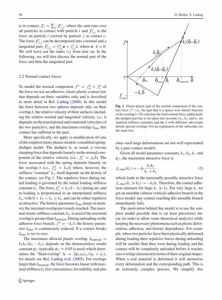
More specifically, we apply (a modification of) oneof the simplest elasto-plastic models: a modified spring-dashpot model. The dashpot is, as usual, a viscousdamping force that depends linearly on the normal com-ponent of the relative velocity (i.e., f n
v = γn δ̇). Theforce associated with the spring depends linearly onthe overlap δ (i.e., f n
el = k∗δ) where, however, thestiffness “constant” k∗, itself depends on the history ofthe contact, see Fig. 1. The repulsive force during ini-tial loading is governed by the initial loading stiffnessconstant k1. The force f n∗ = k∗(δ − δ∗) during un- andre-loading is proportional to an interpolated stiffnessk∗, with 0 < k1 < k∗ ≤ k2, and can be either repulsiveor attractive. The history parameter δmax keeps in mem-ory the maximal overlap previously reached. The maxi-mal elastic stiffness constant, k2, is used if the maximaloverlap is greater than δmaterial. During unloading on theadhesive force branch, f n = −kcδ, the history param-eter δmax is continuously reduced. If a contact breaksδmax is set to zero.
The maximum allowed plastic overlap, δmaterial =k2δf/(k2 − k1), depends on the dimensionless modelconstant φ f (typically φ f ≈ 0.05 is used) which deter-mines the “fluid-overlap” δf = 2φ f ai a j/(ai + a j ),for details see Ref. Luding et al. (2005). For overlapslarger than δmaterial, the force becomes linear with max-imal stiffness k2 (for convenience, for stability, and also
c
*
δ
maxδ δ δδ* material
c,max
−kf
0f
k1δ
δ
f 2k fδ−δ( )
k δ−δ*( )
Fig. 1 Elasto-plastic part of the normal component of the con-tact force f n , i.e., the part that is a (piece-wise linear) functionof the overlap δ. (To calculate the total normal force additionallythe dashpot part has to be taken into account.) k1, k2, and kc arematerial stiffness constants and the δ with different sub-scriptsdenote special overlaps. For an explanation of the subscripts seethe main text.
since such large deformations are not well representedby a pair-contact model).
Given all model parameter constants, k1, k2, kc, andφ f , the maximum attractive force is
fc,max(kc) = −δfkck2
kc + k2, (2)
which leads to the maximally possible attractive forcefc,max(kc � k2)→ −k2δf . Therefore, the contact adhe-sion saturates for large kc � k2. For very large kc weget an unstable (almost vertical) adhesive branch in theforce model: any contact reaching this unstable branchimmediately fails.
The motivation behind this model is to use the sim-plest model possible that is (at least piecewise) lin-ear (in order to allow some theoretical analysis) whilekeeping the necessary phenomena such as plastic defor-mation, adhesion, and history dependence. For exam-ple, when two particles have been plastically deformedduring loading their repulsive forces during unloadingwill be smaller than they were during loading and thecontact will be completely unloaded before it reacheszero overlap (measured in terms of their original shape).When a real material is deformed it will memorizeevery deformation and the corresponding path. This isan extremely complex process. We simplify this
123
Modeling particulate self-healing materials and application to uni-axial compression 91
complex process by keeping in memory only the max-imum overlap a contact has suffered in the past. Thisallows us to model elasticity, plastic deformation, andadhesion to some extent. It does not represent all otherpossible complex mechanisms at contacts of particles.In that respect our model is a compromise between “assimple as possible” and “realistic enough” for our pur-poses.
2.3 Tangential contact forces
In the tangential direction, the forces and torquesdepend on the tangential displacement and the relativerotations of the particle surfaces. Dynamic (sliding) andstatic friction depend on the tangential component ofthe relative velocity of the contact points,
vt = vi j − n(n · vi j ), (3)
where vi j = vi − v j + a′in × ωi + a′
jn × ω j (4)
is the relative velocity of the particle surfaces at con-tact. Here, a′
α = aα −δ/2, for α = i, j , is the correctedradius relative to the contact point. vi , v j , ωi , and ω j
are the linear and rotational velocities of particles i andj , respectively.
Tangential forces f t acting on the contacts are mod-eled to be proportional to the accumulated slidingdistance of the contact points along each other with a(tangential) stiffness constant kt , i.e., f t = kt
∫vt dt .
Including also a viscous dependent damping constant,γt , the tangential force is limited by the product of thenormal force and the contact friction coefficient µ, acco-rding to Coulombs law, f t ≤ µ f n , for more details seeRef. Luding (2008). Note, however, that this commonlyused tangential force model is rather simple—leavingmost of the complexity in the normal force model.
2.4 Background viscous damping
Viscous dissipation as mentioned above takes placelocalized in a two-particle contact only. In the bulkmaterial, where many particles are in contact with eachother, this dissipation mode is very inefficient forlong-wavelength cooperative modes of motion, espe-cially when linear force laws are involved Luding et al.(1994b). Therefore, an additional (artificial) dampingwith the background is introduced, such that the totalforce f i and torque q i | j := a′
jn × f i | j on particle iare given by
f i =∑
j
f nn + f t t − γbvi and
qi =∑
j
q i | j − γbr a2i ωi ,
where the sums take into account all contact partners jof particle i , and γb and γbr are the (artificial) back-ground damping viscosities assigned to the transla-tional and rotational degrees of freedom, respectively.The viscosities can be seen as originating from a vis-cous inter-particle medium and enhance the dampingin the spirit of a rapid relaxation and equilibration. Notethat the effect of γb and γbr should be checked for eachset of parameters: it should be small in order to rule outartificial over-damping.
2.5 Contact model parameters and units
In the following we measure length in units of 1 mm,mass in 1 mg and time in 1µs. Note that only a fewparameters have to be specified with dimensions, whilethe others are expressed as dimensionless ratios inTable 1.
A maximal stiffness constant of k2 = 5, as usedin our simulations, corresponds to a typical contactduration (half-period) tc ≈ 6.5 × 10⁻⁴ for a typi-cal collision of a large and a small particle with γ = 0.Accordingly, an integration time-step tMD = 5 × 10⁻⁶
is used in order to allow for a “safe” integration of theequations of motion. Note that not only the normal“eigenfrequency”, but also the eigen frequencies forthe rotational degrees of freedom have to be consid-ered as well as the viscous response times tγ ≈ m/γ .All of the physical time scales (inverse eigen frequen-cies) should be considerably larger than tMD, while theviscous response times should be even larger, such thattγ > tc > tMD. A more detailed discussion of all theeffects due to the interplay between the model param-eters and the related times is, however, far from thescope of this paper and can be found in Ref. Luding(2008).
3 Tablet preparation and material failure test
3.1 Tablet preparation
Having introduced the model and its parameters in thelast section we describe now the experimental setup
123
92 O. Herbst, S. Luding
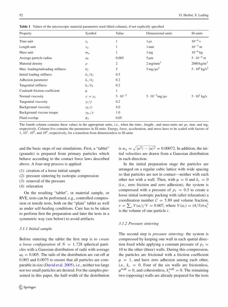
Table 1 Values of the microscopic material parameters used (third column), if not explicitly specified
Property Symbol Value Dimensional units SI-units
Time unit tu 1 1 µs 10−6 s
Length unit xu 1 1 mm 10−3 m
Mass unit mu 1 1 mg 10−6 kg
Average particle radius a0 0.005 5 µm 5 · 10−6 m
Material density ρ 2 2 mg/mm3 2000 kg/m3
Max. loading/unloading stiffness k2 5 5 mg/µs2 5 · 106 kg/s2
Initial loading stiffness k1/k2 0.5
Adhesion parameter kc/k2 0.2
Tangential stiffness kt/k2 0.2
Coulomb friction coefficient µ 1
Normal viscosity γ = γn 5 · 10−5 5 · 10−5mg/µs 5 · 101 kg/s
Tangential viscosity γt/γ 0.2
Background viscosity γb/γ 4.0
Background viscous torque γbr /γ 1.0
Fluid overlap φ f 0.05
The fourth column contains these values in the appropriate units, i.e., when the time-, length-, and mass-units are µs, mm, and mg,respectively. Column five contains the parameters in SI-units. Energy, force, acceleration, and stress have to be scaled with factors of1, 103, 109, and 109, respectively, for a transition from dimensionless to SI-units
and the basic steps of our simulations. First, a “tablet”(granule) is prepared from primary particles whichbehave according to the contact force laws describedabove. A four-step process is applied:
(1) creation of a loose initial sample(2) pressure sintering by isotropic compression(3) removal of the pressure(4) relaxation
On the resulting “tablet”, or material sample, orRVE, tests can be performed, e.g., controlled compres-sion or tensile tests, both on the “plain” tablet as wellas under self-healing conditions. Care has to be takento perform first the preparation and later the tests in asymmetric way (see below) to avoid artifacts.
3.1.1 Initial sample
Before sintering the tablet the first step is to createa loose configuration of N = 1,728 spherical parti-cles with a Gaussian distribution of radii with averagea0 = 0.005. The tails of the distribution are cut-off at0.003 and 0.0075 to ensure that all particles are com-parable in size (David et al. 2005), i.e., neither too largenor too small particles are desired. For the samples pre-sented in this paper, the half-width of the distribution
is wa = √〈a2〉 − 〈a〉2 = 0.00072. In addition, the ini-tial velocities are drawn from a Gaussian distributionin each direction.
In the initial preparation stage the particles arearranged on a regular cubic lattice with wide spacingso that particles are not in contact—neither with eachother nor with a wall. Then, with µ = 0 and kc = 0(i.e., zero friction and zero adhesion), the system iscompressed with a pressure of p1 = 0.5 to create aloose initial isotropic packing with (after relaxation) acoordination number C = 5.89 and volume fraction,ν = ∑
i V (ai )/V = 0.607, where V (ai ) = (4/3)πa3i
is the volume of one particle i .
3.1.2 Pressure sintering
The second step is pressure sintering: the system iscompressed by keeping one wall in each spatial direc-tion fixed while applying a constant pressure of ps =10 to the other (three) walls. During this compression,the particles are frictional with a friction coefficientµ = 1, and have zero adhesion among each other,i.e., kc = 0. Four of the six walls are frictionless,µwall = 0, and cohesionless, kwall
c = 0. The remainingtwo (opposing) walls are already prepared for the tests
123

Modeling particulate self-healing materials and application to uni-axial compression 93
to come: these two walls define the uni-axial directionand are strongly adhesive, with kwall
c /k2 = 20, such thatthe sample sticks to them, while all other walls canbe easily removed in the third step described below.The wall adhesion has no visible effect here, since thesample is strongly confined. In contrast, friction hasan effect, i.e., friction with the walls would hinder thepressure to be transferred completely to the oppositewall. Frictional walls carry part of the load—an effectthat has been known since the early work of Janssen(1895); Sperl (2006).
In Fig. 2 the kinetic energy and the mean coordi-nation number are shown as functions of time duringcompression (step 2): the kinetic energy first increaseswith the smoothly and slowly increasing wall-velocity(see below). Then it decreases due to the energy dis-sipation in the system. After the desired pressure isreached, it is kept constant until the kinetic energy hasvery well reached a tiny value, within fluctuations onlydue the numerical accuracy limit.
A rather high volume fraction, ν = 0.6754, isreached during the pressure sintering. The correspond-
ing coordination number is C ≈ 7.17 in this state. Afterstress-relaxation down to a negligible residual stress(see below), these values will decrease considerably toν ≈ 0.627 and C ≈ 6.097, but remain larger than afterthe initial preparation.
3.1.3 Pressure release
Using the pressure sintered sample, the third step is toremove the pressure from the walls. Before, we do sokc is set to its desired initial value, i.e., kc/k2 = 0.2.
The control pressure is smoothly released from thewalls in a co-sinusoidal way. Starting from its sinteringvalue, ps = 10, down to a residual value, p0, that isfive orders of magnitude lower, i.e., p0/ps = 10−5.The half period of the co-sinusoidal pressure release ist0 = 12.5, see first marker (open circle) in Fig. 3, butrelaxation is continued further until the kinetic energy isdissipated and reaches tiny values at much larger times.The small residual pressure keeps single particles fromaccidentally leaving the sample and also keeps the wallsclose to the sample. (This is important in order to not
Fig. 2 Kinetic energy Ekin(left) and coordinationnumber C (right) asfunctions of time t duringisotropic pressure sinteringwith final pressure ps = 10.Here the particle contactsare adhesionless, kc = 0,while the other parametersare given in Table 1
10-25
10-20
10-15
10-10
10-5
0.0001 0.001 0.01 0.1 1 10
Eki
n
t
5.8
6
6.2
6.4
6.6
6.8
7
7.2
7.4
0.0001 0.001 0.01 0.1 1 10
C
t
Fig. 3 Kinetic energy Ekin(left) and coordinationnumber C (right) asfunctions of time t duringsmooth stress-removal fromthe walls and subsequentrelaxation. The threemarkers in the left graphindicate the end of thepressure decrease and thetwo changes in therelaxation proceduredescribed in the text 10-25
10-20
10-15
10-10
10-5
0.01 0.1 1 10 100
Eki
n
t
5.8
6
6.2
6.4
6.6
6.8
7
7.2
7.4
0.001 0.01 0.1 1 10 100
C
t
123

94 O. Herbst, S. Luding
spoil the efficiency of our linked cell algorithm, wherethe cell size is a fraction of the system size between thewalls.) However, this confining stress p0/ps is not bigenough to affect the dynamics of the tests performed,i.e., tests with p0/ps = 10−3 lead to practically iden-tical results, concerning final density and coordinationnumber.
3.1.4 Final relaxation
The fourth preparation step is the final relaxation of thesystem. This is done in three substeps. First, immedi-ately after the control pressure on the wall has reachedits low residual value, the system is relaxed further untiltime tr1 = 200 (with three fixed walls and three wallswith the residual pressure reached at the end of thewall removal procedure in order to remove any resid-ual center-of-mass velocity). Second, after the kineticenergy has reached and maintained the small value,within fluctuations, for a long time, the system is fur-ther relaxed and symmetrized with the same pressure ofp0 = 10−4 applied from all sides for another time inter-val of tr2 = 50. In the final relaxation step, again a timeinterval of tr3 = 50, the two walls in the x-direction arefixed and the other four walls are kept at the residualpressure. We now have a representative volume ele-ment (RVE) sample with fixed walls in the x-directionand mobile walls with negligible stresses (i.e. virtuallyunconfined walls) in the y and z directions.
The prepared sample can now be used for all sorts oftests. It is almost cubical with side length L0 = 0.1133.The tests to be described in this study are uni-axiallydeforming the walls in the x direction while keepingthe other walls at pressure p0 = 10−4. In the next sub-section we will show a simple compression test of ourparticulate material without self-healing, before, in therest of the paper, especially in Sect. 5, we will deal withcompression tests of self-healing materials.
3.2 Compression test
In this section we describe an uni-axial compressiontest, starting from the final configuration as describedin the previous subsection. This test resembles a directmeasurement of the unconfined yield-strength, asapplied in mechanical engineering and particle tech-nology (Schwedes 2003).
We perform a strain controlled symmetric compres-sion test by moving inwards two opposing walls. Wedirectly move the walls in a cosinusoidal way for upto half a period, i.e., the relative wall position δw(t) =w(t) − w(0) = (Acos/2)(1 − cos (2π t/τcos)), withcompression positive, where Acos is the amplitude, ormaximal compression distance, and τcos is the com-pression “period”. (Note that the maximal compressiondistance is reached after half a period.)
For a representative volume element (RVE) like oursample, we quantify the deformation in terms of thestrain imposed from two sides ε(t) = 2δw(t)/L0,with the maximum strain εcos = 2Acos/L0. The time-derivative of the strain leads to the (time-dependent)compression rateR(t) := ∂ε/∂t = Rcos sin (2π t/τcos)
with the maximum compression rateRcos = 2πεcosτ−1cos
reached at a quarter-period.Depending on the rate of compression different
stress–strain behavior is observed, see related literature(Luding and Herrmann 2001). In Fig. 4 the stress-strainresponse for two different compression periods, τcos =8 (fast) and τcos = 320 (quasi-static), is presented foran amplitude of Acos = 0.04, i.e., εcos ≈ 0.706. Themaximal compression rates Rcos are reached at strainεcos/2 (data not shown). In this paper most compressiontests are presented up to a maximal strain of ε = 0.05,which is already in the critical flow regime. The peak-stress, i.e., the maximal stress, is reached at smallerstrains, εmax ≈ 0.01, so that the relevant strain-rateis much smaller, but still proportional to the inverseperiod 1/τcos, which will be given in the following.
In the compression tests with small and moderaterates, the initial stress–strain relation is very close tolinear, with slope C = ∂σ/∂ε = 225.6, i.e., the ratedependence is not visible in the elastic regime. Thus,up to a strain of about one percent the system behavesalmost like an elastic solid, and only close to maximumstress and during softening, the rate effects becomeimportant.
Figure 5 shows the maximum stress as a functionof the compression rate. Only the lowest data points(1/τcos ≤ 0.01) are in the (truly) quasi-static regime:even slower compression rates lead to the same qual-itative stress-strain diagrams—up to fluctuations. Forlarger rates the stress–strain behavior changes fromquasi-brittle to ductile-like, i.e., from sharp drops tosmoother behavior due to viscous damping. Therefore,we denote deformation rates 1/τcos ≤ 0.01 as quasi-static, those with 0.01 < 1/τcos ≤ 0.2 as (moderately)
123

Modeling particulate self-healing materials and application to uni-axial compression 95
Fig. 4 Normalized axialstress plotted against axialstrain for fast (τcos = 8 and1/τcos = 0.125) and slow(τcos = 320 and1/τcos = 0.003125)compression, withσ0 = k2/a0 = 103
0
0.0005
0.001
0.0015
0.002
0.0025
0.003
0 0.01 0.02 0.03 0.04 0.05
σ / σ
0
ε
fast compressionslow compression
0.002
0.0025
0.003
0.0035
0.004
0.0045
0.005
0.0055
0.006
0.0065
0.007
0.0075
0.0001 0.001 0.01 0.1 1
σ max
/ σ 0
1/τcos
Fig. 5 Maximum (normalized) stress as a function of the max-imum compression rate 1/τcos. Note the finite non-zero valueas the compression rate becomes quasi-static. Note also that forfast compressions the increase in stress is significant, in the datapresented in this graph up to three times the quasi-static value
fast, and those with 1/τcos > 0.2 as very fast. The quasi-static compression is consistent with brittle materialbehavior, see, e.g., Fig. 3 in Ref. Brown and Sottos(2000).
4 Self-healing model
To model a self-healing material we need to locallydetect damage and initiate local healing when damageis detected. Again we attempt to use a simple model tocapture the essence of this complex process. Therefore,we introduce the following self-healing scheme that iscompatible with (but not limited to) the contact modeldescribed in Sect. 2:
(1) detect damage (see below, Sect. 4.1),
(2) heal detected damage (see below, Sect. 4.2),(3) run simulation for a time τD,(4) go to 1.
This procedure allows us to set the damage detectionrate 1/τD at which damage is detected (and subsequentself-healing is activated), and to specify the healingsensitivity and the healing strength separately.
4.1 Damage detection
To detect damage we check each contact for two con-ditions:(1) First, we probe the condition
f n ≤ −α kcδ . (5)
Here, f n is the normal component of the force betweenthe two particles involved in the contact as introducedin Sect. 2.1 and α is a tuning constant to adjust the sen-sitivity of damage detection. A negative value of theforce corresponds to an attractive force, see Figs. 1and 6. (More details about the contact model can befound in Ref. Luding (2008).)(2) Secondly, we require the particles to be movingapart from each other, ensuring that only those contactsare considered damaged which are still “endangered”of breaking immediately.
For moderate α < 1, the healing condition in Eq. 5is fulfilled whenever a contact is close to breaking, seeFig. 6. In the extreme case of α ≥ 1, it is very unlikelythat a contact fulfills this condition whereas, in the caseof α ≈ 0 or α < 0 all contacts under weak tension or
123

96 O. Herbst, S. Luding
0
k1δ
δ
f2k
δ
δ−δ( )f
f
cα δcδ−k − k
x
x
x xx
xx
xx
OO
OOO x
xx x
x
xxx
xx
x
xx
xx
xx xx
xx
xxxx
xx
xx
x
xx
xx
x
x x
x
x
x
xx
x
xx
xx
x
xx
x
xO
O OO
OO
Fig. 6 Schematic plot of (some of) the normal forces typicallypresent at a certain time in the system. Each elasto-plastic-adhe-sive contact is represented by a point inside the triangle. (Due toviscous forces some contacts may be situated outside of the tri-angle if the total normal force is considered.) Healing is appliedif the force is smaller than −αkcδ (circles) and if the contactpartners are separating
even under compression fulfill the condition of Eq. 5—corresponding to over-sensitive healing.
This model is inspired by experiments, more pre-cisely by experiments using a healing-agent confinedto capsules which are spread out throughout the matrixmaterial (White et al. 2001): When a certain force isexcerted on a capsule it will rupture. Once a capsuleis broken, the healing agent will flow out and solidify.At the same position, there cannot any further heal-ing because there is no more healing agent available.Different types of capsules and capsule-matrix inter-face can be modeled by different healing sensitivitiesα. The present model does not allow for massive vol-ume changes (as due to foaming or bubbling healingagents).
Figure 7 shows the maximum stress reached dur-ing compression as a function of the sensitivity tuningparameter α (performing the healing described in Sect.4.2 below). As expected, the maximum stress for a sam-ple with self-healing and α ≥ 1 does not differ from theone reached without self-healing. For α < 0 the mate-rial sample becomes very strong since most contactswill be labeled “damaged” (and subsequently healed)at the very first detection step. For the rest of our studywe will use α = 0.9. This value is in a regime wheresmall changes in α will lead to a linear response in themaximum stress observed.
We have also tested applying only the force condi-tion, i.e., initiating healing for all those contacts ful-filling the first condition, i.e., Eq. 5, regardless of their
0.0025
0.003
0.0035
0.004
0.0045
0.005
0.0055
0.006
0.0065
-0.2 0 0.2 0.4 0.6 0.8 1 1.2
σ max
/ σ 0
α
Fig. 7 Dependence of the maximum (normalized) stress reachedby healing with different sensitivities α, for the self-healing adhe-sion parameter kSH = 5 and damage detection rate 1/τD =0.002, while otherwise the same parameters as for Fig. 4 (mod-erately fast) were used. The horizontal line shows the maximumstrength for a sample without self healing
relative velocities. This leads to similar results withmore contacts healed initially but otherwise similarbehavior. Naturally, it leads to a small increase in themaximum stress (less than 10% for the cases studied).In the following only results will be presented whereboth healing criteria (force and separation) are active.
4.2 Healing
Where damage is detected, i.e., where the two damageconditions mentioned in Sect. 4.1 are met, we initi-ate self-healing which we model by (instantaneously)increasing kc to a higher value kSH for both particles ofthat particular contact. This immediately increases theirmaximum possible attractive forces and thus delays oravoids the failure of their contact. Since the value of kSH
sets the final bonding strength of the healing agent, dif-ferent healing agents can be modeled by using differentvalues of kSH.
Note that all contacts parameters, e.g., kc, areassigned to particles, not to contacts. This may (andusually will somewhere in the sample) lead to contactswhose two partners have different values of kc. In thatcase we use an intermediate value k′
c= 2kc,1kc,2/(kc,1+kc,2) (where kc,1 and kc,2 are the kc values for the twoparticles) for that contact. The reasoning behind thismodel is twofold: First it is much easier to keep trackof the kc’s if they are connected to particles instead ofcontacts because this way one neither needs to keeptrack of past contacts after they have opened nor hasto define new contact properties for a new contact.Secondly, it makes the healing a little more non-local
123

Modeling particulate self-healing materials and application to uni-axial compression 97
(and less abrupt) like in the experimental situationwhere the self-healing agent spreads out a little fromthe point where the capsule broke.
5 Compression tests of a self-healing sample
In this section, compression tests of a self-healing mate-rial are presented. Using a fixed healing sensitivity (α =0.9), the effects of the remaining two model parame-ters, i.e., the self-healing adhesion parameter, kSH, andthe damage detection rate, 1/τD, will be studied in moredetail.
5.1 The extreme cases
In Fig. 8, the stress-strain response of a reference sam-ple without self-healing capability, kc = kSH = 1, iscompared to different cases of self-healing. For all thesecases, the compression is quasi-static, with compres-sion period τcos = 320. In order to considerablyincrease the adhesive force, a self-healing adhesionparameter kSH > kc is chosen. This corresponds toan increase of the maximum (possible) adhesive forceby a factor of
ISH := f SHc,max(kc)
fc,max(kc)= kSH(kc/k2 + 1)
kc(kSH/k2 + 1), (6)
which we denote as the self-healing intensity in the fol-lowing. In the case discussed here (kc = 1, kSH = 5,k2 = 5), ISH = 3.
The two extreme cases are the reference sample withno healing at all (kc = kSH = 1) and the case where
kc = kSH = 5 from the very beginning for all contacts.In both cases no damage detection is necessary. In thefirst case all contacts remain unhealed forever while inthe latter case all contacts are already “healed” fromthe very beginning. This case corresponds to the “full”or “pre-emptive” or “global” healing mentioned in Ref.Luding and Suiker (2008). Not surprisingly, it leads tothe strongest increase in material strength.
Additionally, two cases of local self-healing areshown. The only difference between them is their dam-age detection rate, all other parameters are the same asfor the two extreme cases. The damage detection timeintervals τD = 2 and τD = 0.004 are used, which cor-respond to slow (1/τD = 1/2) and fast (1/τD = 250)damage detection, respectively.
Even the slow damage detection increases the mate-rial strength (maximum stress sustained) by about 25%.Fast damage detection leads to a considerably higherincrease in strength (about 100% compared to the sam-ple without self-healing), but does not reach the extremecase of “full” or “pre-emptive” healing, which leads toan increase of about 150%.
In the following, first, the influence of the damagedetection rate is examined in more detail in Subsect.5.2, and second, the effect the healing intensity is stud-ied in Subsect. 5.3.
5.2 Variation of the damage detection rate
In Fig. 9, the stress–strain response is studied for sys-tems with different damage detection rates 1/τD from0.5 to 250 while all other parameters are kept constant.
Fig. 8 Stress-strainresponse of samples with(from top to bottom) “fullpre-emptive” healing(kc = 5), fast damagedetection rate (1/τD = 250),slow damage detection rate(1/τD = 0.5), and withoutself-healing (kc = 1)
0
0.001
0.002
0.003
0.004
0.005
0.006
0 0.01 0.02 0.03 0.04 0.05 0.06 0.07 0.08
σ / σ
0
ε
kc =11/τD =0.51/τD=250
kc=5
123
98 O. Herbst, S. Luding
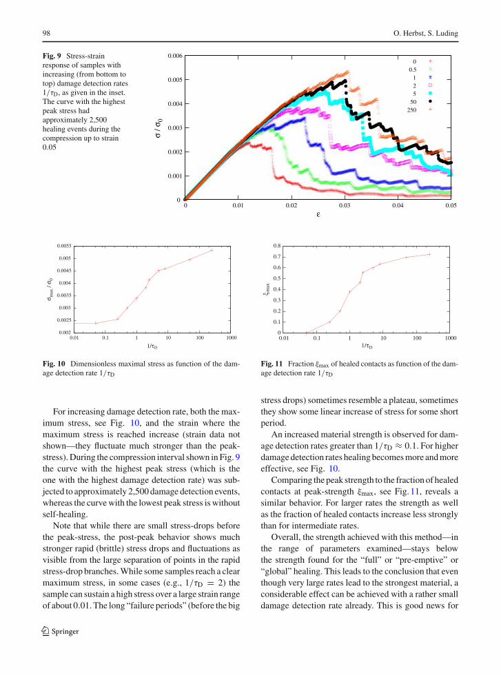
Fig. 9 Stress-strainresponse of samples withincreasing (from bottom totop) damage detection rates1/τD, as given in the inset.The curve with the highestpeak stress hadapproximately 2,500healing events during thecompression up to strain0.05
0
0.001
0.002
0.003
0.004
0.005
0.006
0 0.01 0.02 0.03 0.04 0.05
σ / σ
0
ε
00.5
125
50250
0.002
0.0025
0.003
0.0035
0.004
0.0045
0.005
0.0055
0.01 0.1 1 10 100 1000
σ max
/ σ 0
1/τD
Fig. 10 Dimensionless maximal stress as function of the dam-age detection rate 1/τD
For increasing damage detection rate, both the max-imum stress, see Fig. 10, and the strain where themaximum stress is reached increase (strain data notshown—they fluctuate much stronger than the peak-stress). During the compression interval shown in Fig. 9the curve with the highest peak stress (which is theone with the highest damage detection rate) was sub-jected to approximately 2,500 damage detection events,whereas the curve with the lowest peak stress is withoutself-healing.
Note that while there are small stress-drops beforethe peak-stress, the post-peak behavior shows muchstronger rapid (brittle) stress drops and fluctuations asvisible from the large separation of points in the rapidstress-drop branches. While some samples reach a clearmaximum stress, in some cases (e.g., 1/τD = 2) thesample can sustain a high stress over a large strain rangeof about 0.01. The long “failure periods” (before the big
0
0.1
0.2
0.3
0.4
0.5
0.6
0.7
0.8
0.01 0.1 1 10 100 1000
ξ max
1/τD
Fig. 11 Fraction ξmax of healed contacts as function of the dam-age detection rate 1/τD
stress drops) sometimes resemble a plateau, sometimesthey show some linear increase of stress for some shortperiod.
An increased material strength is observed for dam-age detection rates greater than 1/τD ≈ 0.1. For higherdamage detection rates healing becomes more and moreeffective, see Fig. 10.
Comparing the peak strength to the fraction of healedcontacts at peak-strength ξmax, see Fig. 11, reveals asimilar behavior. For larger rates the strength as wellas the fraction of healed contacts increase less stronglythan for intermediate rates.
Overall, the strength achieved with this method—inthe range of parameters examined—stays belowthe strength found for the “full” or “pre-emptive” or“global” healing. This leads to the conclusion that eventhough very large rates lead to the strongest material, aconsiderable effect can be achieved with a rather smalldamage detection rate already. This is good news for
123

Modeling particulate self-healing materials and application to uni-axial compression 99
Fig. 12 Stress-strainresponse of samples withdifferent self-healingparameters kSH/kc, as givenin the inset. Note that thecurve with highest stressrepresents a sample with aself-healing adhesionparameter of (only)kSH/kc = 50
0
0.0005
0.001
0.0015
0.002
0.0025
0.003
0.0035
0.004
0 0.01 0.02 0.03 0.04 0.05
σ / σ
0
ε
11.1
25
1050
1000
experiments as it means that the capsules containingthe healing agent need not brake immediately whensubjected to stress.
5.3 Variation of adhesive force (healing intensity)
In Fig. 12 we compare the stress–strain response for dif-ferent self-healing adhesion parameters kSH/kc from 1to 103 but fixed the damage detection rate 1/τD = 1/2.Note again the strong variation in the shape of the crit-ical flow regime. With increasing kSH/kc the strengthof the material, i.e., the maximum stress, increases—within the rather strong variations from one sample tothe other. Interestingly, in this data-set, the largest stressis reached for kSH/kc = 50, and not for kSH/kc = 103.
After carrying out many more simulations with dif-ferent healing parameters kSH, this interesting behaviorcan be understood, see Fig. 13. The material strengthgained by self-healing saturates as the healing intensityISH saturates for large kSH/kc (ISH → 6 for kSH/kc →∞). It is therefore instructive toplot themaximumstresssustained not only as a function of kSH/kc (top graph ofFig. 13), but also as a function of the healing intensity(bottom graph of Fig. 13): for healing intensities ISH upto approximately 5 (equivalent to kSH/kc ≈ 25 in ourcase) the material strength increases approximately lin-early with the healing intensity. However, for larger val-ues of ISH > 5 (kSH/kc > 25) we see strong fluctuations.
We relate these strong fluctuations for kSH/kc > 25(ISH > 5) to the fact that the adhesive branch in theforce-displacement law, see Fig. 1, becomes extremely
0.0018
0.002
0.0022
0.0024
0.0026
0.0028
0.003
0.0032
0.0034
0.0036
0.0038
0.1 1 10 100 1000 10000 100000 1e+06
σ max
/ σ 0
kSH/kc
0.0018
0.002
0.0022
0.0024
0.0026
0.0028
0.003
0.0032
0.0034
0.0036
0.0038
0 1 2 3 4 5 6
σ max
/ σ 0
ISH
Fig. 13 (Top) Maximal stress from simulations as a functionof the self-healing adhesion parameter kSH/kc. (Bottom) Samestress as a function of the healing intensity, see Eq. 5.3
steep: very large kSH (or kc) values lead to a steep,almost infinite slope, while virtually not changing themaximum adhesive force. The steep slope of the modelmeans that a contact that hits the tensile instable branchwill “immediately” break (brittle) since a small ten-sile strain leads to an enormous drop in tensile force.This leads to strong fluctuations because the model does
123

100 O. Herbst, S. Luding
0.12
0.14
0.16
0.18
0.2
0.22
0.24
0.26
0.28
0.3
0.32
0 1 2 3 4 5 6
ξm
ax
ISH
Fig. 14 Fraction of healed contacts as a function of the healingintensity ISH, see Eq. 5.3
not allow contacts to recover after they have opened(δ < 0). Strong loading would be necessary to closethe open contacts so that they can be healed. For smallerkc, a small tensile strain only leads to a small drop ofthe tensile force and thus is less critical.
A comparison with the fraction of healed contactsas a function of the healing intensity ISH, see Fig. 14,reveals a rather weak, discontinuous dependence of thefraction of healed contacts on the intensity of healing.There is a clearly visible trend but within large fluctu-ations.
6 Summary and conclusions
We have presented a model for self-healing in particu-late materials based on a recently proposed piecewiselinear contact model for elasto-plastic, adhesive, vis-cous, frictional particle-particle interactions. The con-tact model includes a memory variable, i.e., the contactlaws are history dependent. The proposed self-healingmodel admits to set the damage detection sensitivityand rate as well as the strength of the healed contacts.It could therefore be a reasonable model for a mate-rial including a healing agent in, e.g., capsules. Themodel does not allow for volume change, or to closeopened micro-cracks, as foaming or bubbling self-heal-ing mechanisms could.
Uni-axial unconfined compression has been appliedto isotropically pressure sintered samples and the stressresponse has been studied in the elastic regime, at theonset of, and during failure, as well as in the softeningregime. For fast deformation the material behavior isductile-like due to viscous, velocity dependent forces,whereas for quasi-static deformation it resembles a
brittle material behavior with sharp, rapid drops in stressduring failure and softening.
We found that the elastic regime can be extendedusing self-healing techniques. For a fixed damage sen-sitivity and a fixed damage detection rate, damage isdetected and healed by increasing the adhesive forceinstantaneously if and when the healing criteria (spec-ified in the main text) are fulfilled. The compressiontests of self-healing material samples are compared totwo extreme reference cases: one without healing andone with “full” or “pre-emptive” global healing, wherehealing has been applied to all contacts prior to thecompression test. The model parameters were stud-ied systematically, most prominently by examining thestress–strain response of the samples and additionallyby monitoring the fraction of healed contacts.
The material strength (after healing) increases with(1) the damage detection sensitivity, (2) the damagedetection rate, and (3) the healing intensity (which itselfis a monotonically increasing function of the adhesivestrength of the healed contacts).
(1) A low damage detection sensitivity leads to unsat-isfactory self-healing since too few contacts willbe healed. On the other hand, a very high dam-age detection sensitivity results in healing of con-tacts that are not critical. Healed contacts, withinthe framework of our model, once healed cannotbe healed again when they become critical againin the future. This mimics, e.g., a one-time heal-ing agent which is common in experiments where,e.g., capsules are used.
(2) The damage detection rate allows to set a delay orrelaxation time between damage detection events.Too small a damage detection rate does not allowfor (enough) healing to take place as many criticalcontacts are missed whereas for very large dam-age detection rates the material strength shouldsaturate once the detection rate has reached thesmallest physical time scale. The damage detectionrate, together with the damage detection sensitiv-ity, allows to simulate various types of responses todamage, e.g., more brittle or softer capsules con-taining the healing agent and/or different responsetime scales of the healing agent.
(3) The healing intensity is a non-linear function of theadhesion parameter kSH. It saturates for large kSH
and sets the strength of the healed contacts. Withincreasing healing intensity the material can sus-
123

Modeling particulate self-healing materials and application to uni-axial compression 101
tain larger stresses and fails at higher strains. As afunction of kSH the material strength shows strongfluctuations for large kSH, i.e., in the regime wherethe healing intensity is almost constant. These fluc-tuations are due to local contact instabilities. Forvery large healing intensities, i.e., for very largeadhesive strength of the healed contacts, a con-tact rapidly fails when the tensile limit is reached,resembling a local, brittle failure at the contactlevel. Thus, moderate values for the adhesive con-stant after healing, kSH, lead to the “best” healingresults. The fraction of healed contacts increases alittle with the healing intensity, which correspondsto the final strength of the (solidified) healing agent,i.e., the strength of the final bonding.
To sum up, our model is consistent with, e.g., materialscontaining healing-agents in capsules. Once a capsuleis broken and local healing has taken place, there can-not be any further healing at the same position. Dif-ferent types of capsules and capsule-matrix interfacecan be modeled by different damage detection sensi-tivities and damage detection rates. Different bondingstrengths of the healing agent can be modeled by adjust-ing the self-healing adhesive strength kSH.
The quantitative tuning of the DEM model to realexperimental data remains a challenge for futureresearch. The results presented here have units that arenot (yet) supposed to mimic a real material. Some tun-ing can be done by rescaling, but a real fine-adjustmentwill require a comparison with appropriate experimen-tal data.
The model can also be extended to include an addi-tional time scale on which—after damage is detectedand healing is initiated—the strength slowly increasesto mimic the “bonding” or “hardening” of the heal-ing agent. Work along this line is in progress. Anotherway to extend this work could be to allow for repeatedhealing through a cascade of healing with ever increas-ing adhesive contact force (at the same position). Thefinal challenge remains to observe a healing result thatis superior to the (much simpler) global, pre-emptivehealing of all contacts.
Acknowledgements The authors wish to thank Akke Suiker,Orion Mouraille, and Christine Herbst for useful discussions.This study was made possible by the Delft Center for MaterialsSelf-Healing program, and supported by the research instituteIMPACT of the University of Twente, and the Stitching voorFundamenteel Onderzoek der Materie (FOM), financially sup-
ported by the Nederlandse Organisatie voor WetenschappelijkOnderzoek (NWO), through the Granular Matter program.
Open Access This article is distributed under the terms of theCreative Commons Attribution Noncommercial License whichpermits any noncommercial use, distribution, and reproductionin any medium, provided the original author(s) and source arecredited.
References
Abrams DA (1918) Design of concrete mixtures Bulletin I.Structural Materials Research Laboratory, Lewis Institute,Chicago, Illinois 309–330
Agnolin I, Jenkins JT, Ragione LL (2006) A continuum theoryfor a random array of identical, elastic, frictional disks.Mech Mater 38(8–10):687–701
Allen MP, Tildesley DJ (1987) Computer simulation of liquids.Oxford University Press, Oxford
Balazs AC (2007) Modeling self-healing materials. Mater Today10(9):18–23
Barbero E, Greco F, Lonetti P (2005) Continuum damage-healing mechanics with application to self-healing compos-ites. Int J Damage Mech 14(1):51–81
Bashir YM, Goddard JD (1991) A novel simulation method forthe quasi-static mechanics of granular assemblages. J Rheol35(5):849–885
Behringer RP (1993) The dynamics of flowing sand. NonlinearSci Today 3:1–15
Behringer RP, Baxter GW (1994) Pattern formation and com-plexity in granular flow. In: Mehta A (ed) Granular mat-ter. 85
Brandeis F (1937) Autogenous healing of concrete. Beton undEisen 36:12
Brown E, Sottos N (2000) Performance of embedded micro-spheres for self-healing polymer composites, preprinthttp://www.autonomic.uiuc.edu/brown_files/EricBrownSEM2000.pdf
Brown EN, Kessler MR, Sottos NR (2003a) In situ poly(urea-formaldehyde) microencapsulation of dicyclopentadiene.J Microencapsul 20:719–730
Brown EN, Moore JS, White SR, Sottos NR (2003b) Fractureand fatigue behavior of a self-healing polymer. Mat ResSoc Symp Proc 735: C11.22.1
Brown EN, White SR, Sottos NR (2005) Retardation and repairof fatigue cracks in a microcapsule toughened epoxy com-posite part II: in situ self-healing. Compos Sci Technol65:2474–2480
Burton DS, Goa X, Brinson LC (2006) Finite element simula-tion of a self-healing shape memory alloy composite. MechMater 38(5-6):525–537
Castellanos A (2005) The relationship between attractive inter-particle forces and bulk behavior in dry and uncharged finepowders. Adv Phys 54(4):263–376
Cordier P, Tournilhac F, Soulié-Ziakovic C, Leibler L (2008)Self-healing and thermoreversible rubber from supramo-lecular assembly. Nature 451:977–980
Cundall PA, Strack ODL (1979) A discrete numerical model forgranular assemblies. Géotechnique 29(1):47–65
123
102 O. Herbst, S. Luding
David CT, Rojo RG, Herrmann HJ, Luding S (2005) Hysteresisand creep in powders and grains. In: Garcia-Rojo R, Herr-mann HJ, McNamara S (eds) Powders and grains 2005.Balkema Leiden, Netherlands pp 291–294
Dry C (1994) Matrix cracking repair and filling using active andpassive modes for smart timed release of chemicals fromfibers into cement matrices. Smart Mater Struct 3:118–123
Dry C (1996a) Smart bridge and building materials in whichcyclic motion is controlled by internally released adhesives.Proc SPIE 2719:247–254
Dry C (1996b) Procedures developed for self-repair of polymericmatrix composite materials. Compos Struct 35:263–269
Dry CM Smart-fiber-reinforced matrix composites, U.S. Patent5,803,963
Feng W, Patel SH, Young M-Y, Zunino JLIII, Xanthos M (2007)Smart polymeric coatings—recent advances. Adv PolymTechnol 26(1):1–13
Goldhirsch I, Zanetti G (1993) Clustering instability in dissipa-tive gases. Phys Rev Lett 70(11):1619–1622
Guo Y, Guo W (2006) Self-healing properties of flaws in nano-scale materials: Effects of soft and hard molecular dynam-ics simulations and boundaries studied using a continuummechanical model. Phys Rev B 73:085411
Hearn N (1998) Self-sealing, autogenous healing and continuedhydration: what is the difference?. Mater Struct/Materiauxet Constructions 31:563–567
Herbst O, Huthmann M, Zippelius A (2000) Dynamics of ine-lastically colliding spheres with Coulomb friction: relaxa-tion of translational and rotational energy. Granul Matter2(4):211–219
Herbst O, Cafiero R, Zippelius A, Herrmann HJ, LudingS (2005) A driven two-dimensional granular gas withCoulomb friction. Phys Fluids 17:107102
Herrmann HJ, Hovi J-P, Luding S (eds) (1998) Physics of drygranular media—NATO ASI Series E 350. Kluwer Aca-demic Publishers, Dordrecht
Jaeger HM, Nagel SR (1992) Physics of the granular state. Sci-ence 255:1523
Jaeger HM, Liu C, Nagel SR (1989) Relaxation at the angle ofrepose. Phys Rev Lett 62(1):40–43
Jaeger HM, Liu C, Nagel SR, Witten TA (1990) Friction in gran-ular flows. Europhys Lett 11(7):619–624
Janssen HA (1895) Versuche über Getreidedruck in Silozellen.Zeitschr d Vereines deutscher Ingenieure 39(35):1045–1049
Kafui KD, Thornton C (2000) Numerical simulations of impactbreakage of spherical crystalline agglomerate. PowderTechnol 109:113–132
Kersey FR, Loveless DM, Craig SL (2007) A hybrid polymer gelwith controlled rates of cross-link rupture and self-repair.J Roy Soc Interface 4:373–380
Kessler MR (2007) Self-healing: a new paradigm in materialsdesign, Proc I MECH E Part G J Aerosp Eng 221(4):479–495(17)
Kessler MR, Sottos NR, White SR (2003) Self-healing struc-tural composite materials. Compos Part A Appl Sci Manuf34(8):743–753
Lätzel M, Luding S, Herrmann HJ, Howell DW, BehringerRP (2003) Comparing simulation and experiment of a 2dgranular couette shear device. Eur Phys J E 11(4):325–333
Li VC, Lim YM, Chan Y-W (1998) Feasibility study of a passivesmart self-healing cementitious composite. Compos Part B29:819–827
Luding S (2005a) Shear flow modeling of cohesive and frictionalfine powder. Powder Technol 158:45–50
Luding S (2005b) Anisotropy in cohesive, frictional granularmedia. J Phys Condens Matter 17:S2623–S2640
Luding S (2008) Cohesive frictional powders: contact models fortension. Granul Matter 10:235–246
Luding S, Herrmann HJ (2001) Micro-macro transition for cohe-sive granular media. In: Diebels S (Ed) Bericht Nr. II-7, Instfür Mechanik, Universität Stuttgart
Luding S, Suiker ASJ (2008) Self-healing of damaged particulatematerials through sintering. Philos Mag 88(28–29):3445–3457
Luding S, Clément E, Blumen A, Rajchenbach J, DuranJ (1994a) Studies of columns of beads under external vibra-tions. Phys Rev E 49(2):1634
Luding S, Clément E, Blumen A, Rajchenbach J, DuranJ (1994b) Anomalous energy dissipation in moleculardynamics simulations of grains: The “detachment effect”.Phys Rev E 50:4113
Luding S, Manetsberger K, Muellers J (2005) A discrete modelfor long time sintering. J Mech Phys Solids 53(2):455–491
Maiti S, Shankar C, Geubelle PH, Kieffer J (2006) Continuumand molecular-level modeling of fatigue crack retardationin self-healing polymers. J Eng Mater Technol 128(4):595–602
Mauldin TC, Rule JD, Sottos NR, White SR, Moore JS (2007)Self-healing kinetics and the stereoisomers of dicyclopent-adiene. J Roy Soc Interface 4:389–393
Peizhen H, Zhonghua L, Jun S (2000) Finite element analysison evolution process for damage microcrack healing. ActaMechanica Sinica 16(3):254–263
Pöschel T, Schwager T (2005) Computational granular dynam-ics. Springer, Berlin
Priman V, Dementsov A, Sokolov I (2007) Modeling of self-healing polymer composites reinforced with nanoporousglass fibers. J Comp Theor Nanosci 4:190–193
Rapaport DC (1995) The art of molecular dynamics simulation.Cambridge University Press, Cambridge
Santos A (2008) Does the Chapman-Enskog expansionfor sheared granular gases converge?. Phys Rev Lett100:078003
Schwedes J (2003) Review on testers for measuring flow prop-erties of bulk solids. Granul Matter 5(1):1–45
Sela N, Goldhirsch I (1998) Hydrodynamic equations for rapidflows of smooth inelastic spheres to Burnett order. J FluidMech 361:41–74
Shchukin DG, Möhwald H (2007) Self-repairing coatings con-taining active nanoreservoirs. SMALL 3(6):926–943
Sijbesma RP, Beijer FH, Brunsveld L, Folmer BJB, HirschbergJHKK, Lange RFM, Lowe JKL, Meijer EW (1997) Revers-ible polymers formed from self-complementary monomersusing quadruple hydrogen bonding. Science 278:1601–1604
Soroker VJ, Denson AJ (1926) Autogenous healing of concrete.Zement 25:30
Sperl M (2006) Experiments on corn pressure in silo cells. trans-lation and comment of janssen’s paper from 1895. GranulMatter 8(2):59–65
123

Modeling particulate self-healing materials and application to uni-axial compression 103
Thornton C (2000) Numerical simulations of deviatoric sheardeformation of granular media. Géotechnique 50(1):43–53
Thornton C, Antony SJ (2000) Quasi-static deformation of a softparticle system. Powder Technol 109(1–3):179–191
Thornton C, Yin KK (1991) Impact of elastic spheres with andwithout adhesion. Powder Technol 65:153
Thornton C, Zhang L (2001) A DEM comparison of differentshear testing devices. In: Kishino YPowders and grains.Balkema, Rotterdam pp 183–190
Thornton C, Yin KK, Adams MJ (1996) Numerical simulationof the impact fracture and fragmentation of agglomerates.J Phys D Appl Phys 29:424–435
Tomas J (2004) Fundamentals of cohesive powder consolidationand flow. Granul Matter 6(2/3):75–86
Trask RS, Williams HR, Bond IP (2007a) Self-healing poly-mer composites: mimicking nature to enhance performance.Bioinsp Biomim 2:1–9
Trask RS, Williams GJ, Bond IP (2007b) Bioinspired self-healing of advanced composite structures using hollow glassfibres. J Roy Soc Interface 4:363–371
Turner L The autogenous healing of cement and concrete—itsrelation to vibrated concrete and cracked concrete, Proc. IntAssoc. Testing Materials. Testing Materials, London
van der Zwaag S (ed) (2007) Self-Healing Materials. SpringerVermeer PA, Diebels S, Ehlers W, Herrmann HJ, Luding S,
Ramm E (eds) (2001) Continuous and discontinuous mod-elling of cohesive frictional materials. Springer, Berlin. lec-ture Notes in Physics 568
Vermeer PA, Ehlers W, Herrmann HJ, Ramm E (eds) (2004)Modeling of cohesive-frictional materials. Balkema, Lei-den, Netherlands (ISBN 04 1536 023 4)
Wagner EF (1974) Autogenous healing of cracks in cement-mortar linings for grey-iron and ductile-iron watered pipes.J Am Water Works Assoc 66:358–360
Williams GJ, Trask RS, Bond IP (2007) A self-healing carbonfibre reinforced polymer for aerospace applications. Com-pos Part A Appl Sci Manuf 38(6):1525–1532
White SR, Sottos NR, Geubelle PH, Moore JS, Kessler MR,Sriram SR, Brown EN, Viswanathan S (2001) Autonomichealing of polymer composites. Nature 409:794–797
White SR, Maiti S, Jones AS, Brown EN, Sottos NR, Geu-belle PH (2004) Fatigue of self-healing polymers: multi-scale analysis and experiments, preprint. http://www.icf11.com/proceeding/EXTENDED/5414.pdf
White SR, Sottos NR, Geubelle PH, Moore JS, Sriram SR, Kess-ler MR, Brown EN Multifunctional autonomically healingcomposite material, U.S. Patent 6,518,330
123