Embed Size (px)
Citation preview
Abstract—This paper contains a brief of model building for solid-state breakers (SSB) in electric power distribution systems by using GUI-based (graphic user interface) feature of MATLAB/SIMULINK. Utilization of MATLAB software simplifies problem solving complexity and also reduces working time. In this paper, a 22-kV power distribution feeder with a load having the SSB for protection was situated. The proposed circuit breaker used for modeling is a thyristor-controlled type. Detail of the power circuit and its firing control part was demonstrated in graphical diagrams using elements of the MATLAB’s Power System Blockset (PSB). Test against fault conditions to verify its use was carried out. The results showed that, with a moderate sensing technique to monitor voltage and current of the protected feeder, the SSB can interrupt fault effectively.
Keywords—Solid-state circuit breaker, Thyristor-based switch, MATLAB/SIMULINK, Power system blockset
I. INTRODUCTION
ITH the growing of demand of electric power, the distribution system is expanding continuously. This
results in the high level of short-circuit currents. Therefore, the electric distribution cost such as devices, installation, operation and maintenance increases gradually. Moreover, the high level of short circuit current becomes the serious problem. It may damage the electric devices or effect on machine operation. Continuity of power supply systems is very low because operations of protective devices under faulted conditions. Mechanical circuit breakers in power distribution systems give a safe handling of short-circuits under limited short-circuit power of the grid. Using delayed turn-off times, the circuit breakers can be coordinated with some other protective equipment. Hence, a high availability of the grid can be expected. However, when the short-circuit event occurs in a medium-voltage distribution feeder, voltages along the feeder line are suddenly sagged. Sensitive loads such as computers or electronic-control equipment will fail even if the voltage returns within a few seconds. A solid-state circuit breaker [1-3]
Manuscript received December 10, 2008: Revised version received December 24, 2008.
This work was supported in part by Suranaree University of Technology, Nakhon Ratchasima, Thailand.
T. Kulworawanichpong is with Power System Research Unit, (PSRU), School of Electrical Engineering, Suranaree University of Technology, Nakhon Ratchasima 30000, Thailand (e-mail: [email protected]).
is able to switch at very high speed as fast as voltage or current sensing devices can response to the faulty signal. Although there exist a hundred of commercial software for simulation of electric circuits (e.g. PSPICE [4], ATP/EMTP [5], MATLAB’s PSB [6]-[8], etc), MATLAB is one among them that contains several versatile built-in features in their various TOOLBOX, for example, optimization and control. This facility provided by MATLAB overcomes problem complexity that other commercial software cannot effort. In this paper, a simple thyristor-based circuit breaker was briefly reviewed. Modelling using Power System Blockset [8] considering the requirements of a solid-state switch integrated into a 22-kV medium-voltage power distribution feeder was demonstrated. Based on the thyristor characteristics, triggering signal generation for firing control was also explained. It showed that solid-state breakers offer very fast interruption and can be used in modern medium-voltage power distribution systems. Also, when inverse time-current characteristics were applied to the SSB, it worked well as it was designed for this function.
Development of solid-state breakers has a long history. In literature, solid-state breakers are always embedded into two major useful categories in power system devices: i) solid-state transfer switch and ii) solid-state fault current limiter.
At present, electric power distribution systems are expanding continuously. This results in the high level of feeder current and short circuit current. Therefore, the electric distribution cost such as devices, installation, operation and maintenance increases gradually. Moreover, the high level of short circuit current becomes the serious problem. It may be damage the electric devices or effect to machines operation. The reliability of system is decreased because the operations of protection devices expand the outage area. To solve these problems, the recent study revealed the application of Solid State Fault Current Limiters (SSFCLs) [9] – [25], a vast portion of solid-state breaker applications can be found in literature.
The principles of fault current limitation by a resonant LC circuit was proposed by [17]. This research investigated the reduction of fault current by the insertion of a resonant LC circuit into the transmission line. The device consisted of a capacitor and a thyristor-switched inductance, tuned to the supply frequency. The thyristor switches were operated at zero-current-crossing to eliminate the generation of harmonics. A parametric study determined the effect of components and
Modeling of Solid-state Circuit Breakers using MATLAB’s Power System Blockset
T. Kulworawanichpong
W
INTERNATIONAL JOURNAL OF MATHEMATICS AND COMPUTERS IN SIMULATION
Issue 3, Volume 2, 2008 236
network parameters on the current limiter operation, the results demonstrated that the device can reduced both transient and steady-state fault current significantly.
The reference [16] was presented a microprocessor-controlled variable impedance adaptive fault current limiter. The limiter consisted of an LC series circuit tuned to be of minimum impedance at the supply frequency. A thyristor controlled reactor was shunt connected across the capacitor. By varying the firing angle of a thyristor pair, the impedance of the limiter was varied to allow the necessary current limitation. Therefore, the system is protected and all circuit breaker relays can be operated. The new SSFCL for high voltage power system was proposed by [10]-[11].
Recent development of SSFCLs has been proved the advantage and performance. The fault-current limiter with thyristor-controlled impedance (FCL-TCI) was proposed by [21]. The FCL-TCI helps in improving the steady-state stability limit, while providing an effective reduction of short circuit current during the fault. Effects on improvement of stability limits and reduction of short-circuit current are shown using the experimental model. The economical benefits of the FCL-TCI were due to the extension of the useful life of the existing circuit breakers and transformers and to the improvement in the performance of the transmission line.
Reference [23] presented the need for a distribution current limiting device (DCLD) by the utility industry. The study has evaluated what specifications would be acceptable and what DCLD technique would supply the utility needs. There was no oscillation as well as over voltage excited by the limiter when the fault current was limited.
The principle and characteristics of a fault current limiter with series compensation was proposed by [24]. The FCL components were series capacitor and reactor. A solid-state switch were connected in parallel with the capacitor controls either the ordinal series compensation or fault current limitation. The result of study was presented from the viewpoints of the transient stability improvement and device capacity. The FCL was useful protection device for large, high power transmission system.
The design synthesis of resonant fault current limiter for voltage sag mitigation and current limitation was proposed by [13]. This research presented the shortcomings (transient complications) introduced by the thyristor-controlled resonant FCL proposed by G. G. Karady in the literature. In addition, two modified version of the resonant FCL, with sag mitigation and fault current limiting capabilities, are proposed for use on distribution systems. Sensitivity analysis is the performed on the modified FCLs to determine the effects of component and network parameters on the current limiter performances.
Regarding to reference [13], the voltage quality improvement using the integration of FCL on power system was presented. The research focused on the proper selection and design of suitable solid-state FCL configurations for application on the power system to mitigated voltage sags in term of voltage magnitudes and phase angle jumps. Sensitivity
analysis was also performed to determine the effects of varying FCL parameters on its performance in term of voltage supporting capacity, phase angle jump reduction, and fault current reduction.
The power quality improvement application using SSFLC was proposed by [22]. The enhancement of the quality of supply in distribution networks by minimizing the disturbance to load during the occurrence of a fault was presented. Performance analysis of the proposed device shown that it also had the capability to improve the imbalance between phases during a single-phase to ground fault. This had significant effect on the performance of harmonic sensitive loads such as power electronic converters connected to the system.
The new fault current limiter (FCL) consists of a conventional SCR Bridge FCL was proposed by [19]. With this topology, a fault current let through reactor and a ZnO arrestor. It overcame the limitation of both GTO FCL and SCR Bridge FCL.
The performance evaluation of SSFL in electric distribution system was proposed by [20]. The FCL is evaluated in terms of its performance in limiting fault current to the tolerable limit of the system, as well as the response of the FCL within a fraction of a cycle of about 2 ms. The effects of varying circuit parameters such as R, L, and C as part of the FCL device has been investigated. It has been noted that the inductive reactor, which is part of the FCL device, is suitable for limiting the fault current. Simulation results shown that the FCL was effective for reducing short circuit current and also can be used to protect bus bar from voltage sag when the system was subjected to various types of faults. Finally, the reduction of rating required for circuit breakers by employing series-connected fault current limiters was proposed by [15].
In the model of inductive FCL, a capacitance Cp consisting of a coil stray capacitance and a necessary additional capacitance was taken into account. The insertion of the resistive FCL and the inductive FCL with Cp = 100 nF into the power system proved to decrease the severity of the interrupting duty so that a lower-rated circuit breaker can be used.
The application of a fault current limiter to minimized distributed generation impact on coordinated relay protection was proposed by [18]. This FCL was applied to limit the effect of the distribution generation (DG) on the coordinated relay protection scheme in a radial system during a fault. This research shown that the FCL enhanced the stability of system and limited the transient stresses on the DG. The simulation results shown that in normal operation condition the limiter has no obvious effect on loads. When fault occurred, the bypass reactor was insert the fault line automatically without delay to limit the short circuit current. By the appropriate control strategies, the solid state bridge retreated from the fault line as soon as possible.
As can be seen from the literature given in this paper, majority of solid-state applications is in development of solid-state fault current limiters. However, in this paper, detail of
INTERNATIONAL JOURNAL OF MATHEMATICS AND COMPUTERS IN SIMULATION
Issue 3, Volume 2, 2008 237
SSFCL is not included. It provides only useful information for computer-based simulation using MATLAB’s power system blockset.
This paper was divided into eight main sections. Section II gave a general introduction to MATLAB’s power system blockset to readers. Section III reviewed circuit breaker modeling in the power system blockset. Section IV illustrated solid-state circuit breakers and their model using the power system blockset. The next section, V, gave information for generating firing signals to control thyristor-based switches. Section VI showed algorithms for voltage and current detection to be used together with firing control scheme. Section VII and VIII were simulation results and conclusion.
II. MATLAB’ S POWER SYSTEM BLOCKSET [6]
Interconnections of electric circuit components and electro-mechanical devices such as motors and generators form electrical power systems. The power systems themselves are intrinsically nonlinear. Although some special cases can be treated as linear system, it is limited to a very small area of applications. Engineers working in this particular field are continually asked to enhance the overall system performance to meet its various criteria. Requirements for considerably increased efficiency have forced power system engineers to employ power electronic devices and their sophisticated control systems. Furthermore, it is the fact that the system is often so nonlinear. The only way to understand it with less cost is computer-based simulation.
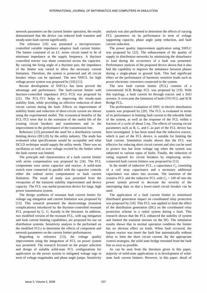
Power generation from hydroelectric, steam, or other gas engines, is not the only use of the MATLAB’s power system blockset. A common attribute of this TOOLBOX is the use of power electronics and their control systems to achieve some desired objectives. The power system blockset was designed to provide a potential tool that will allow engineers to rapidly and easily build models that simulate power systems in various manners. The power system blockset uses the Simulink® environment, allowing a model to be built using simple click and drag procedures. Not only can the circuit topology be drawn rapidly, but the analysis of the circuit can include its interactions with mechanical, thermal, control, and other disciplines. This is possible because all of the electrical parts of the simulation interact with Simulink's extensive modeling library. Since Simulink uses MATLAB® as the computational engine, other efficient MATLAB's toolboxes can also be used by the designer. The power system blockset allows users to build and simulate their own electrical circuits containing linear and/or nonlinear elements. The circuit of Fig. 1 shows a simple power system feeding a 300 km transmission line. The line is compensated by a shunt inductor at its receiving end. A circuit breaker allows energizing and de-energizing of the line. In order to simplify the system, only one of the three phases is represented. This is a so-called “per-phase analysis”. The parameters shown on the figure are typical of a 735 kV power system.
Fig. 1 simple power system to be built using MATLAB’s power
system blockset in Simulink environment
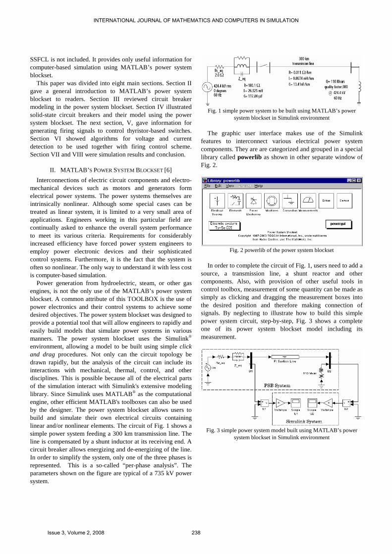
The graphic user interface makes use of the Simulink features to interconnect various electrical power system components. They are are categorized and grouped in a special library called powerlib as shown in other separate window of Fig. 2.
Fig. 2 powerlib of the power system blockset
In order to complete the circuit of Fig. 1, users need to add a
source, a transmission line, a shunt reactor and other components. Also, with provision of other useful tools in control toolbox, measurement of some quantity can be made as simply as clicking and dragging the measurement boxes into the desired position and therefore making connection of signals. By neglecting to illustrate how to build this simple power system circuit, step-by-step, Fig. 3 shows a complete one of its power system blockset model including its measurement.
Fig. 3 simple power system model built using MATLAB’s power
system blockset in Simulink environment
INTERNATIONAL JOURNAL OF MATHEMATICS AND COMPUTERS IN SIMULATION
Issue 3, Volume 2, 2008 238
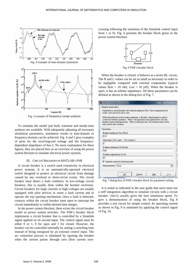
Fig. 4 example of time-domain simulation
Fig. 5 example of frequency-swept analysis
To simulate the model just built, transient and steady-state analyses are available. With adequately adjusting all necessary simulation parameters, simulation results in time-domain or frequency-domain can be achieved. Fig. 4 and 5 give examples of plots for the receiving-end voltage and the frequency-dependent impedance of bus 2. No more explanation for these figures, they are placed here as an overview of using the power system blockset to simulate electrical power systems.
III. CIRCUIT BREAKERS IN MATLAB ’S PSB
A circuit breaker is a switch used extensively in electrical power systems. It is an automatically-operated electrical switch designed to protect an electrical circuit from damage caused by any overload or short-circuit events. The circuit breaker must detect a fault condition. In low-voltage circuit breakers, this is usually done within the breaker enclosure. Circuit breakers for large currents or high voltages are usually equipped with pilot devices to sense a fault current and to operate the trip opening mechanism. Once a fault is detected, contacts within the circuit breaker must open to interrupt the circuit immediately or within desired time margin.
In the power system blockset, there exists the circuit breaker model as power system switches. The PSB’s breaker block implements a circuit breaker that is controlled by a Simulink signal applied on its second input. The control signal must be either 0 or 1, 0 for open and 1 for closed. However, the breaker can be controlled internally by setting a switching time instead of being energized by an external control input. The arc extinction process is simulated by opening the breaker when the current passes through zero (first current zero-
crossing following the transition of the Simulink control input from 1 to 0). Fig. 6 presents the breaker block given in the power system blockset.
Fig. 6 PSB’s breaker block
When the breaker is closed, it behaves as a series RL circuit.
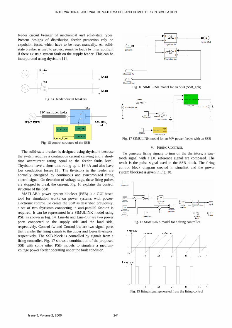
The R and L values can be set as small as necessary in order to be negligible compared with external components (typical values Ron = 10 mΩ, Lon = 10 µH). When the breaker is open, it has an infinite impedance. All these parameters can be defined as shown in the dialog box of Fig. 7.
Fig. 7 dialog box of PSB’s breaker block for parameter setting
It is noted as indicated in the user guide that users must use
a stiff integration algorithm to simulate circuits with a circuit breaker. Ode15s usually gives the best simulation speed. To give a demonstration of using the breaker block, Fig 8 provides a test circuit for simple control. Its operating current as shown in Fig. 9 is simulated by applying the control signal of Fig. 10.
INTERNATIONAL JOURNAL OF MATHEMATICS AND COMPUTERS IN SIMULATION
Issue 3, Volume 2, 2008 239
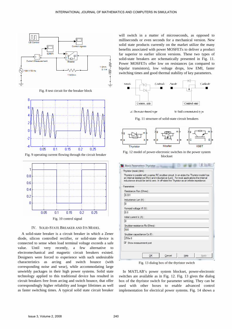
Fig. 8 test circuit for the breaker block
Fig. 9 operating current flowing through the circuit breaker
Fig. 10 control signal
IV. SOLID-STATE BREAKER AND ITS MODEL
A solid-state breaker is a circuit breaker in which a Zener diode, silicon controlled rectifier, or solid-state device is connected to sense when load terminal voltage exceeds a safe value. Until very recently, a few alternative to electromechanical and magnetic circuit breakers existed. Designers were forced to experience with such undesirable characteristics as arcing and switch bounce (with corresponding noise and wear), while accommodating large unwieldy packages in their high power systems. Solid state technology applied to this traditional device has resulted in circuit breakers free from arcing and switch bounce, that offer correspondingly higher reliability and longer lifetimes as well as faster switching times. A typical solid state circuit breaker
will switch in a matter of microseconds, as opposed to milliseconds or even seconds for a mechanical version. New solid state products currently on the market utilize the many benefits associated with power MOSFETs to deliver a product far superior to earlier silicon versions. These two types of solid-state breakers are schematically presented in Fig. 11. Power MOSFETs offer low on resistances (as compared to bipolar transistors), low voltage drops, low EMI, faster switching times and good thermal stability of key parameters.
Fig. 11 structure of solid-state circuit breakers
Fig. 12 model of power-electronic switches in the power system
blockset
Fig. 13 dialog box of the thyristor switch
In MATLAB’s power system blockset, power-electronic
switches are available as in Fig. 12. Fig. 13 gives the dialog box of the thyristor switch for parameter setting. They can be used with other boxes to enable advanced control implementation for electrical power systems. Fig. 14 shows a
INTERNATIONAL JOURNAL OF MATHEMATICS AND COMPUTERS IN SIMULATION
Issue 3, Volume 2, 2008 240
feeder circuit breaker of mechanical and solid-state types. Present designs of distribution feeder protection rely on expulsion fuses, which have to be reset manually. An solid-state breaker is used to protect sensitive loads by interrupting it if there exists a system fault on the supply feeder. This can be incorporated using thyristors [1].
Fig. 14. feeder circuit breakers
Fig. 15 control structure of the SSB
The solid-state breaker is designed using thyristors because
the switch requires a continuous current carrying and a short-time overcurrent rating equal to the feeder faults level. Thyristors have a short-time rating up to 16-kA and also have low conduction losses [1]. The thyristors in the feeder are normally energized by continuous and synchronized firing control signal. On detection of voltage sags, these firing pulses are stopped to break the current. Fig. 16 explains the control structure of the SSB.
MATLAB’s power system blockset (PSB) is a GUI-based tool for simulation works on power systems with power-electronic control. To create the SSB as described previously, a set of two thyristors connecting in anti-parallel fashion is required. It can be represented in a SIMULINK model using PSB as shown in Fig. 14. Line-In and Line-Out are two power ports connected to the supply side and the load side, respectively. Control fw and Control bw are two signal ports that transfer the firing signals to the upper and lower thyristors, respectively. The SSB block is controlled by signals from a firing controller. Fig. 17 shows a combination of the proposed SSB with some other PSB models to simulate a medium-voltage power feeder operating under the fault condition.
Fig. 16 SIMULINK model for an SSB (SSB_1ph)
Fig. 17 SIMULINK model for an MV power feeder with an SSB
V. FIRING CONTROL
To generate firing signals to turn on the thyristors, a saw-tooth signal with a DC reference signal are compared. The result is the pulse signal used in the SSB block. The firing control block diagram created in simulink and the power system blockset is given in Fig. 18.
Fig. 18 SIMULINK model for a firing controller
Fig. 19 firing signal generated from the firing control
INTERNATIONAL JOURNAL OF MATHEMATICS AND COMPUTERS IN SIMULATION
Issue 3, Volume 2, 2008 241
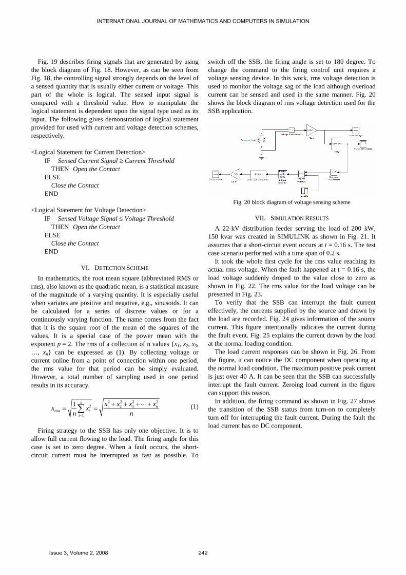
Fig. 19 describes firing signals that are generated by using the block diagram of Fig. 18. However, as can be seen from Fig. 18, the controlling signal strongly depends on the level of a sensed quantity that is usually either current or voltage. This part of the whole is logical. The sensed input signal is compared with a threshold value. How to manipulate the logical statement is dependent upon the signal type used as its input. The following gives demonstration of logical statement provided for used with current and voltage detection schemes, respectively. <Logical Statement for Current Detection>
IF Sensed Current Signal ≥ Current Threshold THEN Open the Contact ELSE Close the Contact END
<Logical Statement for Voltage Detection> IF Sensed Voltage Signal ≤ Voltage Threshold THEN Open the Contact ELSE Close the Contact END
VI. DETECTION SCHEME
In mathematics, the root mean square (abbreviated RMS or rms), also known as the quadratic mean, is a statistical measure of the magnitude of a varying quantity. It is especially useful when variates are positive and negative, e.g., sinusoids. It can be calculated for a series of discrete values or for a continuously varying function. The name comes from the fact that it is the square root of the mean of the squares of the values. It is a special case of the power mean with the exponent p = 2. The rms of a collection of n values x1, x2, x3, …, xn can be expressed as (1). By collecting voltage or current online from a point of connection within one period, the rms value for that period can be simply evaluated. However, a total number of sampling used in one period results in its accuracy.
2 2 2 2
2 1 2 3
1
1 nn
rms ii
x x x xx x
n n=
+ + + += =∑
⋯ (1)
Firing strategy to the SSB has only one objective. It is to
allow full current flowing to the load. The firing angle for this case is set to zero degree. When a fault occurs, the short-circuit current must be interrupted as fast as possible. To
switch off the SSB, the firing angle is set to 180 degree. To change the command to the firing control unit requires a voltage sensing device. In this work, rms voltage detection is used to monitor the voltage sag of the load although overload current can be sensed and used in the same manner. Fig. 20 shows the block diagram of rms voltage detection used for the SSB application.
Fig. 20 block diagram of voltage sensing scheme
VII. SIMULATION RESULTS
A 22-kV distribution feeder serving the load of 200 kW, 150 kvar was created in SIMULINK as shown in Fig. 21. It assumes that a short-circuit event occurs at t = 0.16 s. The test case scenario performed with a time span of 0.2 s.
It took the whole first cycle for the rms value reaching its actual rms voltage. When the fault happened at t = 0.16 s, the load voltage suddenly droped to the value close to zero as shown in Fig. 22. The rms value for the load voltage can be presented in Fig. 23.
To verify that the SSB can interrupt the fault current effectively, the currents supplied by the source and drawn by the load are recorded. Fig. 24 gives information of the source current. This figure intentionally indicates the current during the fault event. Fig. 25 explains the current drawn by the load at the normal loading condition.
The load current responses can be shown in Fig. 26. From the figure, it can notice the DC component when operating at the normal load condition. The maximum positive peak current is just over 40 A. It can be seen that the SSB can successfully interrupt the fault current. Zeroing load current in the figure can support this reason.
In addition, the firing command as shown in Fig. 27 shows the transition of the SSB status from turn-on to completely turn-off for interrupting the fault current. During the fault the load current has no DC component.
INTERNATIONAL JOURNAL OF MATHEMATICS AND COMPUTERS IN SIMULATION
Issue 3, Volume 2, 2008 242
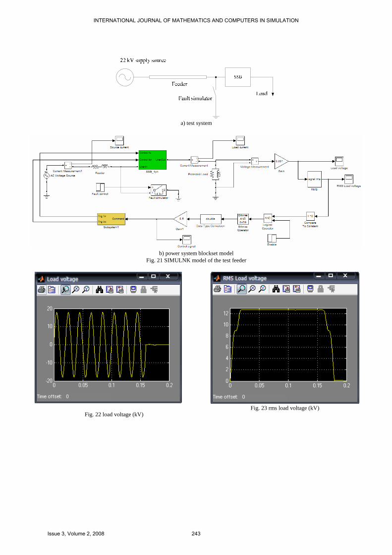
a) test system
b) power system blockset model
Fig. 21 SIMULNK model of the test feeder
Fig. 22 load voltage (kV)
Fig. 23 rms load voltage (kV)
INTERNATIONAL JOURNAL OF MATHEMATICS AND COMPUTERS IN SIMULATION
Issue 3, Volume 2, 2008 243
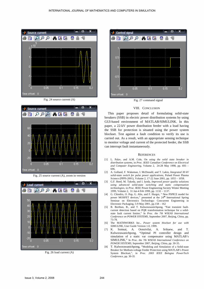
Fig. 24 source current (A)
Fig. 25 source current (A), zoom in version
Fig. 26 load current (A)
Fig. 27 command signal
VIII. CONCLUSION
This paper proposes detail of formulating solid-state breakers (SSB) in electric power distribution systems by using GUI-based environment of MATLAB/SIMULINK. In this paper, a 22-kV power distribution feeder with a load having the SSB for protection is situated using the power system blockset. Test against a fault condition to verify its use is carried out. As a result, with an appropriate sensing technique to monitor voltage and current of the protected feeder, the SSB can interrupt fault instantaneously.
REFERENCES
[1] L. Palav, and A.M. Cole, On using the solid state breaker in distribution systems, in Proc. IEEE Canadian Conference on Electrical and Computer Engineering, Volume 2, 24-28 May 1998, pp. 693 – 696.
[2] A. Golland, F. Wakeman, I. McDonald, and T. Lakin, Integrated 30 kV solid-state switch for pulse power applications, Pulsed Power Plasma Science (PPPS-2001), Volume 2, 17-22 June 2001, pp. 1055 – 1058.
[3] G.F. Reed, M. Takeda, and I. Iyoda, Improved power quality solutions using advanced solid-state switching and static compensation technologies, in Proc. IEEE Power Engineering Society Winter Meeting 1999, Volume 2, 31 Jan-4 Feb 1999, pp. 1132 – 1137.
[4] G. Chindris, O. Pop, G. Alin, and F. Hurgoi, “ New PSPICE model for power MOSFET devices,” presented at the 24th International Spring Seminar on Electronics Technology: Concurrent Engineering in Electronic Packaging, 5-9 May 2001, pp.158 – 162
[5] B. Boribun, B., and T. Kulworawanichpong, “Fast transient fault-current detection based on PQR transformation technique for a solid-state fault current limiter,” In Proc. the 7th WSEAS International Conference on POWER SYSTEMS, September 2007, Beijing, China, pp. 73-78.
[6] The MATHWORKS Inc., Power system blockset for use with SIMULINK, User Guide Version 1.0, 1999.
[7] K. Somsai, A. Oonsivilai, A. Srikaew, and T. Kulworawanichpong, “Optimal PI controller design and simulation of a static var compensator using MATLAB’s SIMULINK,” In Proc. the 7th WSEAS International Conference on POWER SYSTEMS, September 2007, Beijing, China, pp. 30-35.
[8] T. Kulworawanichpong, “Modeling and Simulation of a Solid-state Breaker for Medium-voltage Feeder Protection using MATLAB’s Power System Blockset,”, in Proc. 2003 IEEE Bologna PowerTech Conference, pp. 30-35
INTERNATIONAL JOURNAL OF MATHEMATICS AND COMPUTERS IN SIMULATION
Issue 3, Volume 2, 2008 244
[9] B. Korobeynikov, D. Ishcenko, and A. Iscchenko, "Solid-state fault current limiter for medium voltage distribution systems," in Proc. 2003 IEEE Bologna PowerTech Conference, pp. 1468-1473
[10] C. Gang, J. Daozhuo, L. Zhengyu, and W. Zhaolin, "A new proposal for solid state fault current limiter and its control strategies," in Proc. 2004. IEEE Power Engineering Society General Meeting, pp. 1468-1473.
[11] C. Gang, J. Daozhuo, L. Zhengyu, and W. Zhaolin, "Simulation study on a new solid state fault current limiter for high-voltage power systems," in Proc. 2004 IEEE International Conference on Electric Utility Deregulation, Restructuring and Power Technologies, 2004. (DRPT 2004), pp. 156-160.
[12] C. Meyer, P. Kollensperger, and R. W. De Doncker, "Design of a novel low loss fault current limiter for medium-voltage systems," in Proc. Nineteenth Annual IEEE Applied Power Electronics Conference and Exposition, 2004. APEC '04, pp. 1825–1831.
[13] C. S. Chang and P. C. Loh, "Designs synthesis of resonant fault current limiter for voltage sag mitigation and current limitation," in Proc. 2000. IEEE Power Engineering Society Winter Meeting, pp. 2482-2487.
[14] C. S. Chang and P. C. Loh, "Integration of fault current limiters on power systems for voltage quality improvement," Electric Power Systems Research, vol. 57, pp. 83-92, Mar 2001.
[15] E. Calixte, Y. Yokomizu, H. Shimizu, T. Matsumura, and H. Fujita, "Reduction of rating required for circuit breakers by employing series-connected fault current limiters," IEE Proc. Transm. Distrib., vol. 151, pp. 36-42, Apr. 2004.
[16] E. F. King, A. Y. Chikhani, R. Hackam, and M. M. A. Salama, "A microprocessor-controlled variable impedance adaptive fault current limiter," IEEE Transactions on Power Delivery, vol. 5, pp. 1830-1838, Oct 1990.
[17] G. G. Karady, "Principles of fault current limitation by a resonant LC circuit," IEE Proceedings-Generation, Transmission and Distribution, vol. 139, pp. 1-6, Jan. 1992.
[18] G. Tang and M. R. Iravani, "Application of a fault current limiter to minimize distributed generation impact on coordinated relay protection," in Proc. International Conference on Power Systems Transients (IPST’05), pp. 1-6.
[19] L. Zhengyu, J. Daozhuo, and W. Zhaolin, "A new topology of fault-current limiter and its parameters optimization," in Proc. 2003 IEEE 34th Annual Power Electronics Specialist Conference, 2003. PESC '03, pp. 462-465.
[20] M. A. Hannan and A. Mohamed, "Performance evaluation of solid state fault current limiters in electric distribution system," in Proc. Student Conference on Research and Development, 2003, pp. 245-250.
[21] M. M. A. Salama, H. Temraz, A. Y. Chikhani, and M. A. Bayoumi, " Fault-current limiter with thyristor-controlled impedance," IEEE Transactions on Power Delivery, vol. 8, pp. 1518-1528, Jul 1993.
[22] M. M. R. Ahmed, G. A. Putrus, and L. Ran, "Power quality improvement using a solid-state fault current limiter," in Proc. Transmission and Distribution Conference and Exhibition 2002: Asia Pacific. IEEE/PES, pp. 1059-1064.
[23] P. G. Slade, J. L. Wu, E. J. Stacey, W. F. Stubler, R. E. Voshall, J. J. bonk, J. Porter, and L. Hong, "The utility requirements for a distribution fault current limiter," IEEE Transactions on Power Delivery, vol. 7, pp. 507-515, Apr. 1992.
[24] S. Sugimoto, J. Kida, J., H. Arita, C. Fukui, and T. Yamagiwa, "Principle and characteristics of a fault current limiter with series compensation," IEEE Transactions on Power Delivery, vol. 11, pp. 842-847, Apr. 1996.
[25] V. K. Sood and R. Amin, "EMTP RV-based study of solid-state fault current limiter for distribution systems," in Proc. 2006 IEEE Power India Conference, pp.
Thanatchai Kulworawanichpong was born in Nakhon Ratchasima, on January 20, 1975. He received his B.Eng. from Suranaree University of Technology, Nakhon Ratchasima, Thailand in 1998 and his M.Eng. from Chulalongkorn University, Bangkok, Thailand in 2000, both in Electrical Engineering. He also got his Ph.D. from the University of Birmingham, England, 2004.
His employment experience started with teaching assistant in 1998 at School of Electrical Engineering, Suranaree University of Technology. In 2000, he was promoted to be a full-time lecturer of the same
school. Again, he was promoted to be an assistant professor of electrical engineering as his current position up-to-now.
He became a member of several well-known academic societies, such as, WSEAS, IEEE, IET, IEEJ, WASET, IASTED, etc. Also he has usually served these societies as their referee for reviewing submitted papers to their journals. His special fields of interest included electrical machines, power electronic control and drives, soft computing, modeling and simulation with advanced numerical techniques, and electrical power system analysis.
INTERNATIONAL JOURNAL OF MATHEMATICS AND COMPUTERS IN SIMULATION
Issue 3, Volume 2, 2008 245