Embed Size (px)
Citation preview
February 2007
CA08101001E For more information visit:
www.eaton.com
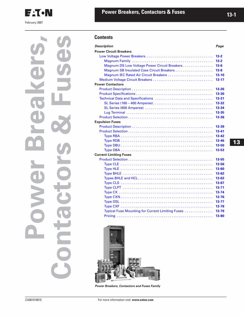
Contents
Power Breakers, Contactors & Fuses 13-1
13
Po
we
r B
reakers
,C
on
tacto
rs &
Fu
ses
Description Page
Power Circuit Breakers
Low Voltage Power Breakers. . . . . . . . . . . . . . . . . . . . . . . . . . . . . . . . . . . .
13-2
Magnum Family . . . . . . . . . . . . . . . . . . . . . . . . . . . . . . . . . . . . . . . . . . .
13-2
Magnum DS Low Voltage Power Circuit Breakers . . . . . . . . . . . . . . . .
13-6
Magnum SB Insulated Case Circuit Breakers . . . . . . . . . . . . . . . . . . . .
13-8
Magnum IEC Rated Air Circuit Breakers . . . . . . . . . . . . . . . . . . . . . . . .
13-10
Medium Voltage Circuit Breakers . . . . . . . . . . . . . . . . . . . . . . . . . . . . . . . .
13-17
Power Contactors
Product Description . . . . . . . . . . . . . . . . . . . . . . . . . . . . . . . . . . . . . . . . . . .
13-26
Product Specifications . . . . . . . . . . . . . . . . . . . . . . . . . . . . . . . . . . . . . . . . .
13-30
Technical Data and Specifications . . . . . . . . . . . . . . . . . . . . . . . . . . . . . . .
13-31
SL Series (160 – 400 Amperes). . . . . . . . . . . . . . . . . . . . . . . . . . . . . . . .
13-32
SL Series (800 Amperes) . . . . . . . . . . . . . . . . . . . . . . . . . . . . . . . . . . . .
13-34
Lug Terminal . . . . . . . . . . . . . . . . . . . . . . . . . . . . . . . . . . . . . . . . . . . . . .
13-35
Product Selection . . . . . . . . . . . . . . . . . . . . . . . . . . . . . . . . . . . . . . . . . . . . .
13-36
Expulsion Fuses
Product Description . . . . . . . . . . . . . . . . . . . . . . . . . . . . . . . . . . . . . . . . . . .
13-39
Product Selection . . . . . . . . . . . . . . . . . . . . . . . . . . . . . . . . . . . . . . . . . . . . .
13-41
Type RBA . . . . . . . . . . . . . . . . . . . . . . . . . . . . . . . . . . . . . . . . . . . . . . . . .
13-42
Type RDB . . . . . . . . . . . . . . . . . . . . . . . . . . . . . . . . . . . . . . . . . . . . . . . . .
13-46
Type DBU . . . . . . . . . . . . . . . . . . . . . . . . . . . . . . . . . . . . . . . . . . . . . . . . .
13-50
Type DBA . . . . . . . . . . . . . . . . . . . . . . . . . . . . . . . . . . . . . . . . . . . . . . . . .
13-53
Current Limiting Fuses
Product Selection . . . . . . . . . . . . . . . . . . . . . . . . . . . . . . . . . . . . . . . . . . . . .
13-55
Type CLE . . . . . . . . . . . . . . . . . . . . . . . . . . . . . . . . . . . . . . . . . . . . . . . . .
13-56
Type HLE . . . . . . . . . . . . . . . . . . . . . . . . . . . . . . . . . . . . . . . . . . . . . . . . .
13-60
Type BHLE . . . . . . . . . . . . . . . . . . . . . . . . . . . . . . . . . . . . . . . . . . . . . . . .
13-62
Types BHLE and HCL. . . . . . . . . . . . . . . . . . . . . . . . . . . . . . . . . . . . . . . .
13-63
Type CLS . . . . . . . . . . . . . . . . . . . . . . . . . . . . . . . . . . . . . . . . . . . . . . . . .
13-67
Type CLPT . . . . . . . . . . . . . . . . . . . . . . . . . . . . . . . . . . . . . . . . . . . . . . . .
13-71
Type CX . . . . . . . . . . . . . . . . . . . . . . . . . . . . . . . . . . . . . . . . . . . . . . . . . .
13-74
Type CXN . . . . . . . . . . . . . . . . . . . . . . . . . . . . . . . . . . . . . . . . . . . . . . . . .
13-76
Type DSL . . . . . . . . . . . . . . . . . . . . . . . . . . . . . . . . . . . . . . . . . . . . . . . . .
13-77
Type CXF . . . . . . . . . . . . . . . . . . . . . . . . . . . . . . . . . . . . . . . . . . . . . . . . .
13-78
Typical Fuse Mounting for Current Limiting Fuses . . . . . . . . . . . . . . .
13-79
Pricing . . . . . . . . . . . . . . . . . . . . . . . . . . . . . . . . . . . . . . . . . . . . . . . . . . .
13-80
Power Breakers, Contactors and Fuses Family

February 2007
13-2
For more information visit:
www.eaton.com
CA08101001E
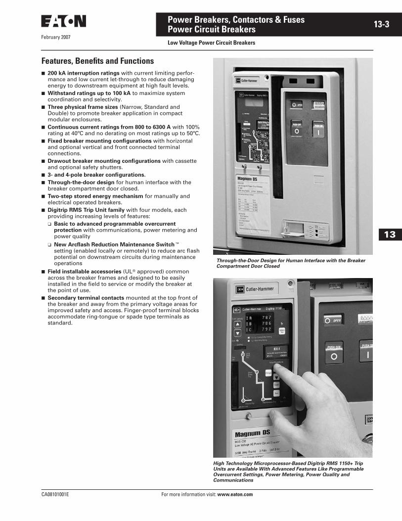
Power Breakers, Contactors & Fuses
13
Power Circuit Breakers
Low Voltage Power Circuit Breakers
Magnum Low Voltage Power Circuit Breakers for Global Application
Magnum
�
Low Voltage Power Circuit Breakers enable comprehensive solutions to meet and exceed the unique and wide-ranging requirements of today’s global power distribution systems. This powerful circuit breaker offering is designed for ultimate custom configuration and applica-tion flexibility, with the needs of the power distribution equipment user and the electrical equipment manufacturer in mind.
Three Product Families
Magnum consists of three product families; each provides specific ratings features and approvals to optimize perfor-mance when applied in power distribution equipment and custom enclosures:
Magnum DS Low Voltage Power Circuit Breakers for ANSI Rated Switchgear Applications
■
Up to 635 Vac.
■
200 to 6000 A continuous.
■
42 to 200 kA interrupting.
Magnum DS Low Voltage Power Circuit Breaker Family ANSI Rated
for Switchgear Applications
Magnum SB Low Voltage Insulated Case Circuit Breakers for Switchboard Applications
■
Up to 635 Vac.
■
200 to 5000 A continuous.
■
50 to 150 kA interrupting.
Magnum SB Low Voltage Insulated Case Circuit Breaker Family UL
Rated for Switchboard Applications
Magnum IEC Air Circuit Breakers for IEC Rated Switchboards
■
Up to 690 Vac.
■
200 to 6300 A continuous.
■
40 to 100 kA I
cu
/I
cs.
Magnum IEC Low Voltage Air Circuit Breaker Family
February 2007
CA08101001E For more information visit:
www.eaton.com
13-3Power Breakers, Contactors & Fuses
13
Power Circuit Breakers
Low Voltage Power Circuit Breakers
Features, Benefits and Functions
■
200 kA interruption ratings
with current limiting perfor-mance and low current let-through to reduce damaging energy to downstream equipment at high fault levels.
■
Withstand ratings up to 100 kA
to maximize system coordination and selectivity.
■
Three physical frame sizes
(Narrow, Standard and Double) to promote breaker application in compact modular enclosures.
■
Continuous current ratings from 800 to 6300 A
with 100% rating at 40ºC and no derating on most ratings up to 50ºC.
■
Fixed breaker mounting configurations
with horizontal and optional vertical and front connected terminal connections.
■
Drawout breaker mounting configurations
with cassette and optional safety shutters.
■
3- and 4-pole breaker configurations.
■
Through-the-door design
for human interface with the breaker compartment door closed.
■
Two-step stored energy mechanism
for manually and electrical operated breakers.
■
Digitrip RMS Trip Unit family
with four models, each providing increasing levels of features:
❑
Basic to advanced programmable overcurrent protection
with communications, power metering and power quality
❑
New Arcflash Reduction Maintenance Switch
�
setting (enabled locally or remotely) to reduce arc flash potential on downstream circuits during maintenance operations
■
Field installable accessories
(UL
�
approved) common across the breaker frames and designed to be easily installed in the field to service or modify the breaker at the point of use.
■
Secondary terminal contacts
mounted at the top front of the breaker and away from the primary voltage areas for improved safety and access. Finger-proof terminal blocks accommodate ring-tongue or spade type terminals as standard.
Through-the-Door Design for Human Interface with the Breaker
Compartment Door Closed
High Technology Microprocessor-Based Digitrip RMS 1150+ Trip
Units are Available With Advanced Features Like Programmable
Overcurrent Settings, Power Metering, Power Quality and
Communications

February 2007
13-4
For more information visit:
www.eaton.com
CA08101001E
Power Breakers, Contactors & Fuses
13
Power Circuit Breakers
Low Voltage Power Circuit Breakers
Breaker Features on Front Cover
The controls and indicators are func-tionally grouped on the breaker face-plate to optimize the human interface, visibility, and ease of use. For maxi-mum safety, a modern, through-the-door design permits access to the breaker levering system, trip unit, controls and indicators with the door closed.
�
Mechanical Trip Flag Pop-out Indicator (Optional) — Red
�
Accessory Viewing Windows for:
❑
Shunt Trip Attachment (STA)
❑
Spring Release Device (SR)
❑
Undervoltage Release (UVR) Device or Second STA
�
Digitrip RMS Trip Unit (Model 520M Shown) Protected by Clear Cover
�
Contact Status Indicators:
❑
OPEN — Green
❑
CLOSED — Red
�
Spring Status Indicators:
❑
Charged — Yellow
❑
Discharged — White
�
Push OFF (Open) Pushbutton —Red
�
Push ON (Close) Pushbutton — Green
Manual Spring Charging Handle for Manually Charging the Stored Energy Springs
Mechanical Operations Counter (Optional)
�
Key Off Lock (Optional)
�
Padlockable Levering Device Shutter for Drawout Breakers
Color-Coded Position Indicator for Drawout Breakers:
❑
CONNECT — Red
❑
TEST — Yellow
❑
DISCONNECT — Green
Magnum DS Drawout Breaker
Accessory Viewing Windows Visibly
Confirm the Breaker Shunt Trip, Spring
Release, and UVR Installation and Their
Control Voltage Rating
Through-the-Door Design for Human
Interface with the Breaker Compartment
Door Closed, for Example, Manually
Charging the Stored Energy Springs
Drawout Breaker Levering Can be
Accomplished With the Compartment
Door Closed Without the Need for a
Special Levering Tool
� � �
�
��
�
�
�
February 2007
CA08101001E For more information visit:
www.eaton.com
13-5Power Breakers, Contactors & Fuses
13
Power Circuit Breakers
Low Voltage Power Circuit Breakers
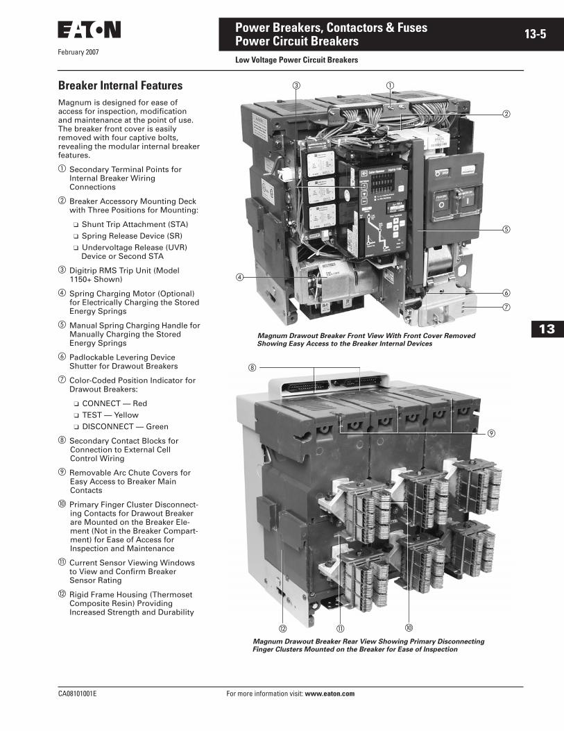
Breaker Internal Features
Magnum is designed for ease of access for inspection, modification and maintenance at the point of use. The breaker front cover is easily removed with four captive bolts, revealing the modular internal breaker features.
�
Secondary Terminal Points for Internal Breaker Wiring Connections
�
Breaker Accessory Mounting Deck with Three Positions for Mounting:
❑
Shunt Trip Attachment (STA)
❑
Spring Release Device (SR)
❑
Undervoltage Release (UVR) Device or Second STA
�
Digitrip RMS Trip Unit (Model 1150+ Shown)
�
Spring Charging Motor (Optional) for Electrically Charging the Stored Energy Springs
�
Manual Spring Charging Handle for Manually Charging the Stored Energy Springs
� Padlockable Levering Device Shutter for Drawout Breakers
� Color-Coded Position Indicator forDrawout Breakers:
❑ CONNECT — Red❑ TEST — Yellow❑ DISCONNECT — Green
Secondary Contact Blocks for Connection to External Cell Control Wiring
Removable Arc Chute Covers for Easy Access to Breaker Main Contacts
� Primary Finger Cluster Disconnect-ing Contacts for Drawout Breaker are Mounted on the Breaker Ele-ment (Not in the Breaker Compart-ment) for Ease of Access for Inspection and Maintenance
� Current Sensor Viewing Windows to View and Confirm Breaker Sensor Rating
Rigid Frame Housing (Thermoset Composite Resin) Providing Increased Strength and Durability
Magnum Drawout Breaker Front View With Front Cover Removed
Showing Easy Access to the Breaker Internal Devices
Magnum Drawout Breaker Rear View Showing Primary Disconnecting
Finger Clusters Mounted on the Breaker for Ease of Inspection
�
�
�
�
�
�
�
� �
February 2007
13-6
For more information visit: www.eaton.com CA08101001E
Power Breakers, Contactors & Fuses
13
Power Circuit BreakersLow Voltage Power Circuit Breakers
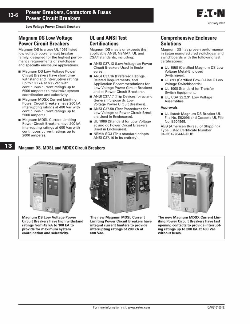
Magnum DS Low Voltage Power Circuit BreakersMagnum DS is a true UL 1066 listed low voltage power circuit breaker family, designed for the highest perfor-mance requirements of switchgear and specialty enclosure applications.
■ Magnum DS Low Voltage Power Circuit Breakers have short time withstand and interruption ratings up to 100 kA at 635 Vac with continuous current ratings up to 6000 amperes to maximize system coordination and selectivity.
■ Magnum MDSX Current Limiting Power Circuit Breakers have 200 kA interrupting ratings at 480 Vac with continuous current ratings up to 5000 amperes.
■ Magnum MDSL Current Limiting Power Circuit Breakers have 200 kA interrupting ratings at 600 Vac with continuous current ratings up to 2000 amperes.
UL and ANSI Test CertificationsMagnum DS meets or exceeds the applicable ANSI, NEMA�, UL and CSA� standards, including:
■ ANSI C37.13 (Low Voltage ac Power Circuit Breakers Used in Enclo-sures).
■ ANSI C37.16 (Preferred Ratings, Related Requirements, and Application Recommendations for Low Voltage Power Circuit Breakers and ac Power Circuit Breakers).
■ ANSI C37.17 (Trip Devices for ac and General Purpose dc Low Voltage Power Circuit Breakers).
■ ANSI C37.50 (Test Procedures for Low Voltage ac Power Circuit Break-ers Used in Enclosures).
■ UL 1066 (Standard for Low Voltage ac and dc Power Circuit Breakers Used in Enclosures).
■ NEMA SG3 (This standard adopts ANSI C37.16 in its entirety).
Comprehensive Enclosure SolutionsMagnum DS has proven performance in Eaton manufactured switchgear and switchboards with the following test certifications:
■ UL 1558 (Certified Magnum DS Low Voltage Metal-Enclosed Switchgear).
■ UL 891 (Certified Pow-R-Line C Low Voltage Switchboards).
■ UL 1008 Standard for Transfer Switch Equipment.
■ UL, CSA 22.2.31 Low Voltage Assemblies.
Approvals
■ UL listed: Magnum DS Breaker UL File No. E52096 and Cassette UL File No. E204565.
ABS (American Bureau of Shipping) Type Listed Certificate Number 04-HS422844A-DUB.
Magnum DS, MDSL and MDSX Circuit Breakers
Magnum DS Low Voltage Power Circuit Breakers have high withstand ratings from 42 kA to 100 kA to provide for maximum system coordination and selectivity.
The new Magnum MDSL Current Limiting Power Circuit Breakers have integral current limiters to provide interrupting ratings of 200 kA at 600 Vac.
The new Magnum MDSX Current Lim-iting Power Circuit Breakers have fast opening contacts to provide interrupt-ing ratings up to 200 kA at 480 Vac without fuses.
February 2007
CA08101001E For more information visit: www.eaton.com
13-7Power Breakers, Contactors & Fuses
13
Power Circuit BreakersLow Voltage Power Circuit Breakers
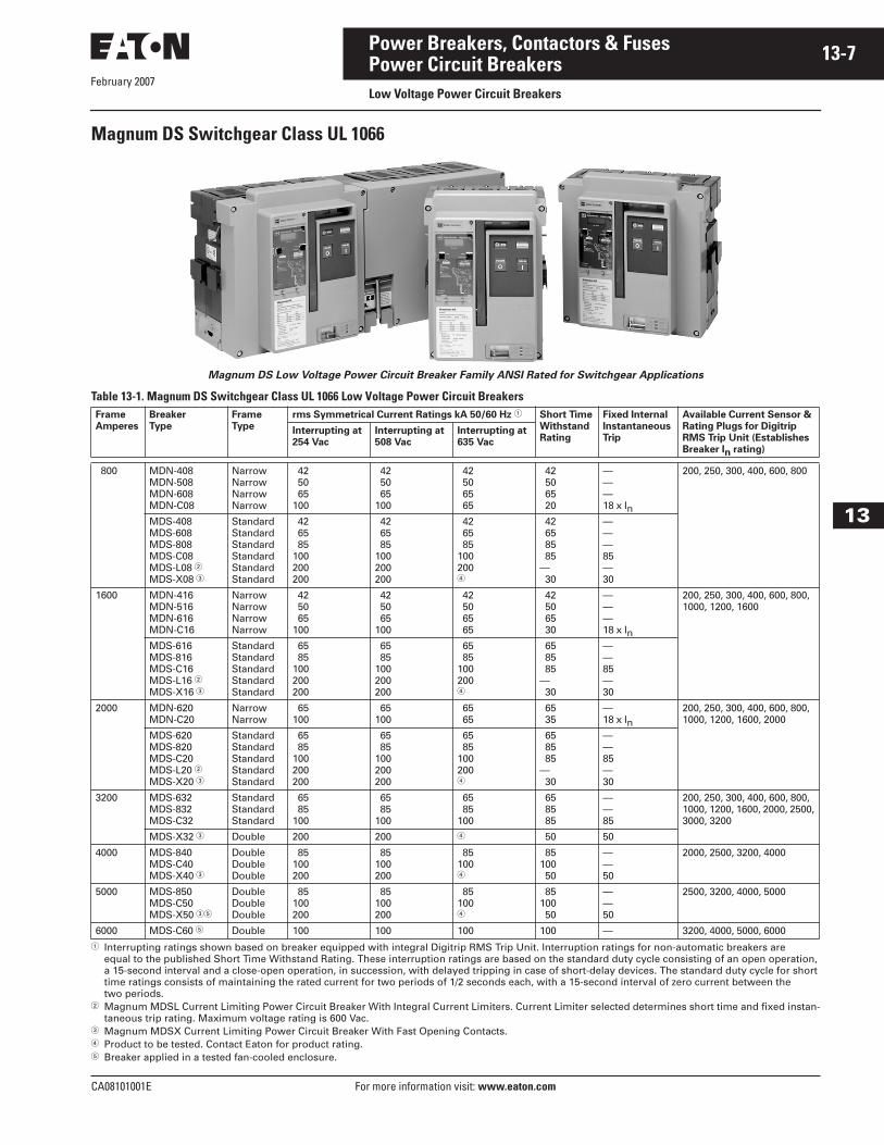
Magnum DS Switchgear Class UL 1066
Magnum DS Low Voltage Power Circuit Breaker Family ANSI Rated for Switchgear Applications
Table 13-1. Magnum DS Switchgear Class UL 1066 Low Voltage Power Circuit Breakers
� Interrupting ratings shown based on breaker equipped with integral Digitrip RMS Trip Unit. Interruption ratings for non-automatic breakers are equal to the published Short Time Withstand Rating. These interruption ratings are based on the standard duty cycle consisting of an open operation, a 15-second interval and a close-open operation, in succession, with delayed tripping in case of short-delay devices. The standard duty cycle for short time ratings consists of maintaining the rated current for two periods of 1/2 seconds each, with a 15-second interval of zero current between the two periods.
� Magnum MDSL Current Limiting Power Circuit Breaker With Integral Current Limiters. Current Limiter selected determines short time and fixed instan-taneous trip rating. Maximum voltage rating is 600 Vac.
� Magnum MDSX Current Limiting Power Circuit Breaker With Fast Opening Contacts.� Product to be tested. Contact Eaton for product rating.� Breaker applied in a tested fan-cooled enclosure.
Frame
Amperes
Breaker
Type
Frame
Type
rms Symmetrical Current Ratings kA 50/60 Hz � Short Time
Withstand
Rating
Fixed Internal
Instantaneous
Trip
Available Current Sensor &
Rating Plugs for Digitrip
RMS Trip Unit (Establishes
Breaker In rating)
Interrupting at
254 Vac
Interrupting at
508 Vac
Interrupting at
635 Vac
800 MDN-408MDN-508MDN-608MDN-C08
NarrowNarrowNarrowNarrow
42 50 65100
42 50 65100
42 50 65 65
42 50 65 20
———18 x In
200, 250, 300, 400, 600, 800
MDS-408MDS-608MDS-808MDS-C08MDS-L08 �MDS-X08 �
StandardStandardStandardStandardStandardStandard
42 65 85100200200
42 65 85100200200
42 65 85100200�
42 65 85 85— 30
———85—30
1600 MDN-416MDN-516MDN-616MDN-C16
NarrowNarrowNarrowNarrow
42 50 65100
42 50 65100
42 50 65 65
42 50 65 30
———18 x In
200, 250, 300, 400, 600, 800, 1000, 1200, 1600
MDS-616MDS-816MDS-C16MDS-L16 �MDS-X16 �
StandardStandardStandardStandardStandard
65 85100200200
65 85100200200
65 85100200�
65 85 85— 30
——85—30
2000 MDN-620MDN-C20
NarrowNarrow
65100
65100
65 65
65 35
—18 x In
200, 250, 300, 400, 600, 800, 1000, 1200, 1600, 2000
MDS-620MDS-820MDS-C20MDS-L20 �MDS-X20 �
StandardStandardStandardStandardStandard
65 85100200200
65 85100200200
65 85100200�
65 85 85— 30
——85—30
3200 MDS-632MDS-832MDS-C32
StandardStandardStandard
65 85100
65 85100
65 85100
65 85 85
——85
200, 250, 300, 400, 600, 800, 1000, 1200, 1600, 2000, 2500, 3000, 3200
MDS-X32 � Double 200 200 � 50 50
4000 MDS-840MDS-C40MDS-X40 �
DoubleDoubleDouble
85100200
85100200
85100�
85100 50
——50
2000, 2500, 3200, 4000
5000 MDS-850MDS-C50MDS-X50 ��
DoubleDoubleDouble
85100200
85100200
85100�
85100 50
——50
2500, 3200, 4000, 5000
6000 MDS-C60 � Double 100 100 100 100 — 3200, 4000, 5000, 6000
February 2007
13-8
For more information visit: www.eaton.com CA08101001E
Power Breakers, Contactors & Fuses
13
Power Circuit BreakersLow Voltage Power Circuit Breakers
Magnum SB Low Voltage Insulated Case Circuit Breakers
Magnum SB Low Voltage Insulated Case
Circuit Breakers are Designed for the
Performance and Economic Requirements
of UL 891 Switchboards
Typical Magnum SB Low Voltage Insulated
Case Circuit Breaker Nameplate
Magnum SB is a Low Voltage Insulated Case Circuit breaker family designed for the performance and economic requirements of UL 891 switchboards.
■ Magnum SB Insulated Case Circuit Breakers have Interruption ratings up to 100 kA at 635 Vac with continuous current ratings up to 5000 amperes.
■ Magnum SB Insulated Case Circuit Breakers have lighter-duty Short Time Withstand ratings and fixed internal instantaneous trips on most ratings, which is characteristic of UL 489 molded case breakers commonly used in UL 891 switch-boards. This provides for greater economy and excellent coordination and selectivity for most commercial applications.
■ Fixed internal instantaneous trips will be phased in on all SB Insulated Case Circuit Breakers rated 3200 amperes and below to provide an extra safety factor by reducing the energy let-through to downstream circuits at the maximum instanta-neous trip point and to facilitate feeder circuit breaker protection in UL 891 switchboards with 3-cycle bus bracing.
■ Magnum SBSE Current Limiting Power Circuit Breakers have 150 kA Interrupting Ratings at 480 Vac with continuous current ratings up to 5000 amperes. The Short Time Withstand Rating is 30 kA for standard frame and 50 kA for double frame breakers.
UL & ANSI Test CertificationsMagnum SB meets or exceeds the applicable ANSI, NEMA, UL and CSA standards, including:
■ ANSI C37.13 (Low Voltage AC Power Circuit Breakers Used in Enclosures)
■ ANSI C37.16 (Preferred Ratings, Related Requirements, and Application Recommendations for Low Voltage Power Circuit Breakers and AC Power Circuit Breakers)
■ ANSI C37.17 (Trip Devices for AC and General Purpose DC Low Voltage Power Circuit Breakers)
■ ANSI C37.50 (Test Procedures for Low Voltage AC Power Circuit Breakers Used in Enclosures)
■ UL 1066 (Standard for Low Voltage AC and DC Power Circuit Breakers Used in Enclosures)
■ NEMA SG3 (This standard adopts ANSI C37.16 in its entirety)
Comprehensive Enclosure SolutionsMagnum DS has proven performance in Eaton manufactured switchgear and switchboards with the following test certifications:
■ UL 1558 (Certified Magnum DS Low Voltage Metal-Enclosed switchgear)
■ UL 891 (Certified Pow-R-Line C Low Voltage Switchboards)
■ UL, CSA 22.2.31 Low Voltage Assemblies
Approvals■ UL listed: Magnum DS Breaker
UL File E52096 and Cassette UL File E204565.
February 2007
CA08101001E For more information visit: www.eaton.com
13-9Power Breakers, Contactors & Fuses
13
Power Circuit BreakersLow Voltage Power Circuit Breakers
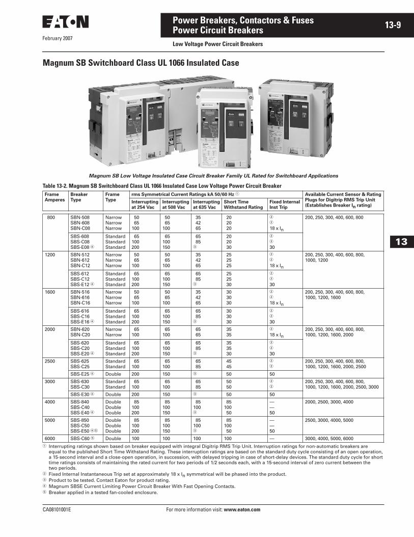
Magnum SB Switchboard Class UL 1066 Insulated Case
Magnum SB Low Voltage Insulated Case Circuit Breaker Family UL Rated for Switchboard Applications
Table 13-2. Magnum SB Switchboard Class UL 1066 Insulated Case Low Voltage Power Circuit Breaker
� Interrupting ratings shown based on breaker equipped with integral Digitrip RMS Trip Unit. Interruption ratings for non-automatic breakers are equal to the published Short Time Withstand Rating. These interruption ratings are based on the standard duty cycle consisting of an open operation, a 15-second interval and a close-open operation, in succession, with delayed tripping in case of short-delay devices. The standard duty cycle for short time ratings consists of maintaining the rated current for two periods of 1/2 seconds each, with a 15-second interval of zero current between the two periods.
� Fixed Internal Instantaneous Trip set at approximately 18 x In symmetrical will be phased into the product.� Product to be tested. Contact Eaton for product rating.� Magnum SBSE Current Limiting Power Circuit Breaker With Fast Opening Contacts.� Breaker applied in a tested fan-cooled enclosure.
Frame
Amperes
Breaker
Type
Frame
Type
rms Symmetrical Current Ratings kA 50/60 Hz � Available Current Sensor & Rating
Plugs for Digitrip RMS Trip Unit
(Establishes Breaker In rating)Interrupting
at 254 Vac
Interrupting
at 508 Vac
Interrupting
at 635 Vac
Short Time
Withstand Rating
Fixed Internal
Inst Trip
800 SBN-508SBN-608SBN-C08
NarrowNarrowNarrow
50 65100
50 65100
35 42 65
20 20 20
�
�
18 x In
200, 250, 300, 400, 600, 800
SBS-608SBS-C08SBS-E08 �
StandardStandardStandard
65100200
65100150
65 85�
20 20 30
�
�
30
1200 SBN-512SBN-612SBN-C12
NarrowNarrowNarrow
50 65100
50 65100
35 42 65
25 25 25
�
�
18 x In
200, 250, 300, 400, 600, 800, 1000, 1200
SBS-612SBS-C12SBS-E12 �
StandardStandardStandard
65100200
65100150
65 85�
25 25 30
�
�
30
1600 SBN-516SBN-616SBN-C16
NarrowNarrowNarrow
50 65100
50 65100
35 42 65
30 30 30
�
�
18 x In
200, 250, 300, 400, 600, 800, 1000, 1200, 1600
SBS-616SBS-C16SBS-E16 �
StandardStandardStandard
65100200
65100150
65 85�
30 30 30
�
�
30
2000 SBN-620SBN-C20
NarrowNarrow
65100
65100
65 65
35 35
�
18 x In200, 250, 300, 400, 600, 800, 1000, 1200, 1600, 2000
SBS-620SBS-C20SBS-E20 �
StandardStandardStandard
65100200
65100150
65 85�
35 35 30
�
�
30
2500 SBS-625SBS-C25
StandardStandard
65100
65100
65 85
45 45
�
�200, 250, 300, 400, 600, 800, 1000, 1200, 1600, 2000, 2500
SBS-E25 � Double 200 150 � 50 50
3000 SBS-630SBS-C30
StandardStandard
65100
65100
65 85
50 50
�
�200, 250, 300, 400, 600, 800, 1000, 1200, 1600, 2000, 2500, 3000
SBS-E30 � Double 200 150 � 50 50
4000 SBS-840SBS-C40SBS-E40 �
DoubleDoubleDouble
85100200
85100150
85100�
85100 50
——50
2000, 2500, 3000, 4000
5000 SBS-850SBS-C50SBS-E50 ��
DoubleDoubleDouble
85100200
85100150
85100�
85100 50
——50
2500, 3000, 4000, 5000
6000 SBS-C60 � Double 100 100 100 100 — 3000, 4000, 5000, 6000
February 2007
13-10
For more information visit: www.eaton.com CA08101001E
Power Breakers, Contactors & Fuses
13
Power Circuit BreakersLow Voltage Power Circuit Breakers
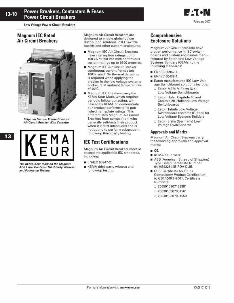
Magnum IEC RatedAir Circuit Breakers
Magnum Narrow Frame Drawout
Air Circuit Breaker With Cassette
The KEMA Keur Mark on the Magnum
ACB Label Confirms Third-Party Witness
and Follow-up Testing
Magnum Air Circuit Breakers are designed to enable global power distribution solutions in IEC switch-boards and other custom enclosures.
■ Magnum IEC Air Circuit Breakers have interruption ratings up to 100 kA at 690 Vac with continuous current ratings up to 6300 amperes.
■ Magnum IEC Air Circuit Breaker continuous current frames are 100% rated. No thermal de-rating is required when applying the breaker in the low voltage systems enclosure at ambient temperatures of 40°C.
■ Magnum IEC Breakers carry the KEMA Keur Mark, which requires periodic follow-up testing, wit-nessed by KEMA, to demonstrate our product performs to its pub-lished nameplate ratings. This differentiates Magnum Air Circuit Breakers from competition, who generally self-tests their product when it is first introduced and is not bound to perform subsequent follow-up third-party testing.
IEC Test CertificationsMagnum Air Circuit Breakers meet or exceed the applicable IEC standards, including:
■ EN/IEC 60947-2.■ KEMA third-party witness and
follow-up testing.
Comprehensive Enclosure SolutionsMagnum Air Circuit Breakers have proven performance in IEC switch-boards and custom enclosures manu-factured by Eaton and Low Voltage Systems Builders (OEMs) to the following standards:
■ EN/IEC 60947-1.■ EN/IEC 60439-1.■ Eaton manufactured IEC Low Volt-
age Switchboard solutions include:❑ Eaton MEM M-Form (UK)
Low Voltage Switchboards❑ Eaton Holec Capitole 40 and
Capitole 20 (Holland) Low Voltage Switchboards
❑ Eaton Tabula Low Voltage Switchboard Systems (Global) for Low Voltage Systems Builders
❑ Eaton Elatis (Germany) Low Voltage Switchboards
Approvals and MarksMagnum Air Circuit Breakers carry the following approvals and approval marks:
■ CE.■ KEMA Keur mark.■ ABS (American Bureau of Shipping)
Type Listed Certificate Number 04-HS422844B-PDA-DUB.
■ CCC (Certificate for China Compulsory Product Certification) to GB14048.2-2001, Certificate Numbers:❑ 2005010307139381❑ 2003010307094561❑ 2003010307094558
February 2007
CA08101001E For more information visit: www.eaton.com
13-11Power Breakers, Contactors & Fuses
13
Power Circuit BreakersLow Voltage Power Circuit Breakers
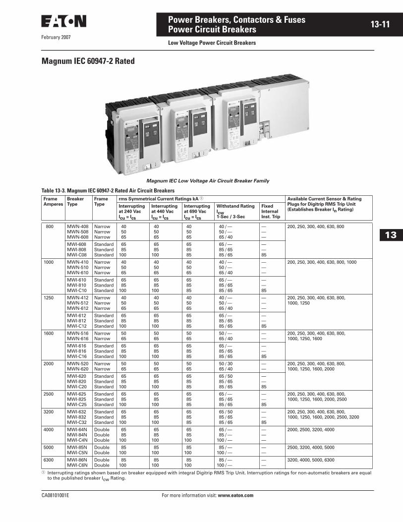
Magnum IEC 60947-2 Rated
Magnum IEC Low Voltage Air Circuit Breaker Family
Table 13-3. Magnum IEC 60947-2 Rated Air Circuit Breakers
� Interrupting ratings shown based on breaker equipped with integral Digitrip RMS Trip Unit. Interruption ratings for non-automatic breakers are equal to the published breaker Icw Rating.
Frame
Amperes
Breaker
Type
Frame
Type
rms Symmetrical Current Ratings kA � Available Current Sensor & Rating
Plugs for Digitrip RMS Trip Unit
(Establishes Breaker In Rating)Interrupting
at 240 Vac
Icu = Ics
Interrupting
at 440 Vac
Icu = Ics
Interrupting
at 690 Vac
Icu = Ics
Withstand Rating
Icw1-Sec / 3-Sec
Fixed
Internal
Inst. Trip
800 MWN-408MWN-508MWN-608
NarrowNarrowNarrow
40 50 65
40 50 65
40 50 65
40 / — 50 / — 65 / 40
———
200, 250, 300, 400, 630, 800
MWI-608MWI-808MWI-C08
StandardStandardStandard
65 85100
65 85100
65 85 85
65 / — 85 / 65 85 / 65
——85
1000 MWN-410MWN-510MWN-610
NarrowNarrowNarrow
40 50 65
40 50 65
40 50 65
40 / — 50 / — 65 / 40
———
200, 250, 300, 400, 630, 800, 1000
MWI-610MWI-810MWI-C10
StandardStandardStandard
65 85100
65 85100
65 85 85
65 / — 85 / 65 85 / 65
——85
1250 MWN-412MWN-512MWN-612
NarrowNarrowNarrow
40 50 65
40 50 65
40 50 65
40 / — 50 / — 65 / 40
———
200, 250, 300, 400, 630, 800, 1000, 1250
MWI-612MWI-812MWI-C12
StandardStandardStandard
65 85100
65 85100
65 85 85
65 / — 85 / 65 85 / 65
——85
1600 MWN-516MWN-616
NarrowNarrow
50 65
50 65
50 65
50 / — 65 / 40
——
200, 250, 300, 400, 630, 800, 1000, 1250, 1600
MWI-616MWI-816MWI-C16
StandardStandardStandard
65 85100
65 85100
65 85 85
65 / — 85 / 65 85 / 65
——85
2000 MWN-520MWN-620
NarrowNarrow
50 65
50 65
50 65
50 / 30 65 / 40
——
200, 250, 300, 400, 630, 800, 1000, 1250, 1600, 2000
MWI-620MWI-820MWI-C20
StandardStandardStandard
65 85100
65 85100
65 85 85
65 / 50 85 / 65 85 / 65
——85
2500 MWI-625MWI-825MWI-C25
StandardStandardStandard
65 85100
65 85100
65 85 85
65 / — 85 / 65 85 / 65
——85
200, 250, 300, 400, 630, 800, 1000, 1250, 1600, 2000, 2500
3200 MWI-632MWI-832MWI-C32
StandardStandardStandard
65 85100
65 85100
65 85 85
65 / 50 85 / 65 85 / 65
——85
200, 250, 300, 400, 630, 800, 1000, 1250, 1600, 2000, 2500, 3200
4000 MWI-64NMWI-84NMWI-C4N
DoubleDoubleDouble
65 85100
65 85100
65 85100
65 / — 85 / —100 / —
———
2000, 2500, 3200, 4000
5000 MWI-85NMWI-C5N
DoubleDouble
85100
85100
85100
85 / —100 / —
——
2500, 3200, 4000, 5000
6300 MWI-86NMWI-C6N
DoubleDouble
85100
85100
85100
85 / —100 / —
——
3200, 4000, 5000, 6300
February 2007
13-12
For more information visit: www.eaton.com CA08101001E
Power Breakers, Contactors & Fuses
13
Power Circuit BreakersLow Voltage Power Circuit Breakers
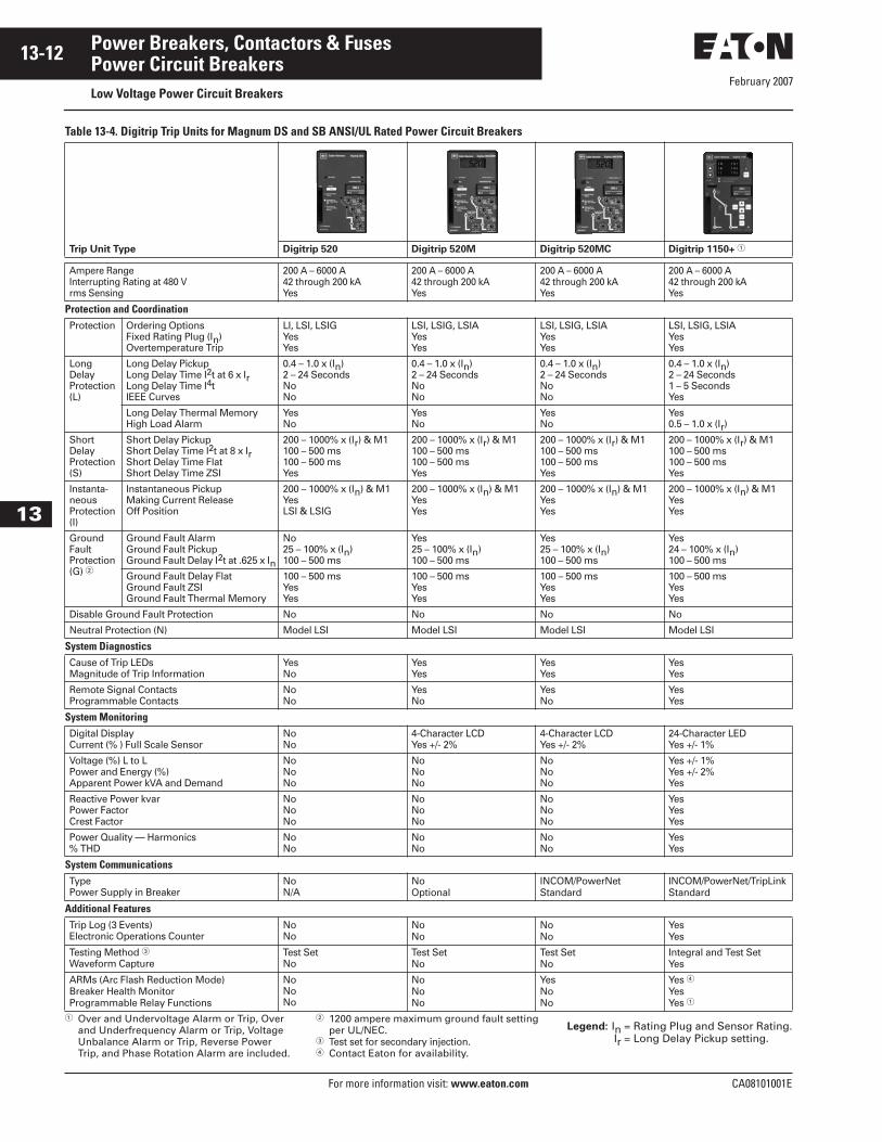
Table 13-4. Digitrip Trip Units for Magnum DS and SB ANSI/UL Rated Power Circuit Breakers
� Over and Undervoltage Alarm or Trip, Over and Underfrequency Alarm or Trip, Voltage Unbalance Alarm or Trip, Reverse Power Trip, and Phase Rotation Alarm are included.
� 1200 ampere maximum ground fault setting per UL/NEC.
� Test set for secondary injection. � Contact Eaton for availability.
Legend: In = Rating Plug and Sensor Rating.Ir = Long Delay Pickup setting.
Trip Unit Type Digitrip 520 Digitrip 520M Digitrip 520MC Digitrip 1150+ �
Ampere RangeInterrupting Rating at 480 Vrms Sensing
200 A – 6000 A42 through 200 kA Yes
200 A – 6000 A42 through 200 kAYes
200 A – 6000 A42 through 200 kAYes
200 A – 6000 A42 through 200 kAYes
Protection and CoordinationProtection Ordering Options
Fixed Rating Plug (In)Overtemperature Trip
LI, LSI, LSIGYesYes
LSI, LSIG, LSIAYesYes
LSI, LSIG, LSIAYesYes
LSI, LSIG, LSIAYesYes
Long DelayProtection (L)
Long Delay Pickup Long Delay Time I2t at 6 x Ir Long Delay Time I4t IEEE Curves
0.4 – 1.0 x (In)2 – 24 SecondsNoNo
0.4 – 1.0 x (In)2 – 24 SecondsNoNo
0.4 – 1.0 x (In)2 – 24 SecondsNoNo
0.4 – 1.0 x (In)2 – 24 Seconds1 – 5 SecondsYes
Long Delay Thermal MemoryHigh Load Alarm
YesNo
YesNo
YesNo
Yes0.5 – 1.0 x (Ir)
Short DelayProtection (S)
Short Delay PickupShort Delay Time I2t at 8 x Ir Short Delay Time FlatShort Delay Time ZSI
200 – 1000% x (Ir) & M1100 – 500 ms100 – 500 msYes
200 – 1000% x (Ir) & M1 100 – 500 ms100 – 500 msYes
200 – 1000% x (Ir) & M1100 – 500 ms100 – 500 msYes
200 – 1000% x (Ir) & M1100 – 500 ms100 – 500 msYes
Instanta-neousProtection (I)
Instantaneous PickupMaking Current ReleaseOff Position
200 – 1000% x (In) & M1YesLSI & LSIG
200 – 1000% x (In) & M1YesYes
200 – 1000% x (In) & M1YesYes
200 – 1000% x (In) & M1YesYes
GroundFaultProtection (G) �
Ground Fault AlarmGround Fault PickupGround Fault Delay I2t at .625 x In
No25 – 100% x (In)100 – 500 ms
Yes25 – 100% x (In) 100 – 500 ms
Yes25 – 100% x (In)100 – 500 ms
Yes24 – 100% x (In)100 – 500 ms
Ground Fault Delay FlatGround Fault ZSIGround Fault Thermal Memory
100 – 500 msYesYes
100 – 500 msYesYes
100 – 500 msYesYes
100 – 500 msYesYes
Disable Ground Fault Protection No No No No
Neutral Protection (N) Model LSI Model LSI Model LSI Model LSI
System DiagnosticsCause of Trip LEDsMagnitude of Trip Information
Yes No
YesYes
Yes Yes
Yes Yes
Remote Signal ContactsProgrammable Contacts
NoNo
Yes No
Yes No
YesYes
System MonitoringDigital DisplayCurrent (% ) Full Scale Sensor
NoNo
4-Character LCDYes +/- 2%
4-Character LCDYes +/- 2%
24-Character LEDYes +/- 1%
Voltage (%) L to L Power and Energy (%) Apparent Power kVA and Demand
NoNoNo
NoNoNo
NoNoNo
Yes +/- 1%Yes +/- 2%Yes
Reactive Power kvarPower FactorCrest Factor
NoNoNo
NoNoNo
NoNoNo
YesYesYes
Power Quality — Harmonics% THD
NoNo
NoNo
NoNo
YesYes
System CommunicationsTypePower Supply in Breaker
NoN/A
NoOptional
INCOM/PowerNetStandard
INCOM/PowerNet/TripLinkStandard
Additional FeaturesTrip Log (3 Events)Electronic Operations Counter
NoNo
NoNo
NoNo
YesYes
Testing Method �Waveform Capture
Test SetNo
Test SetNo
Test SetNo
Integral and Test SetYes
ARMs (Arc Flash Reduction Mode)Breaker Health MonitorProgrammable Relay Functions
NoNoNo
NoNoNo
YesNoNo
Yes �YesYes �
February 2007
CA08101001E For more information visit: www.eaton.com
13-13Power Breakers, Contactors & Fuses
13
Power Circuit BreakersLow Voltage Power Circuit Breakers
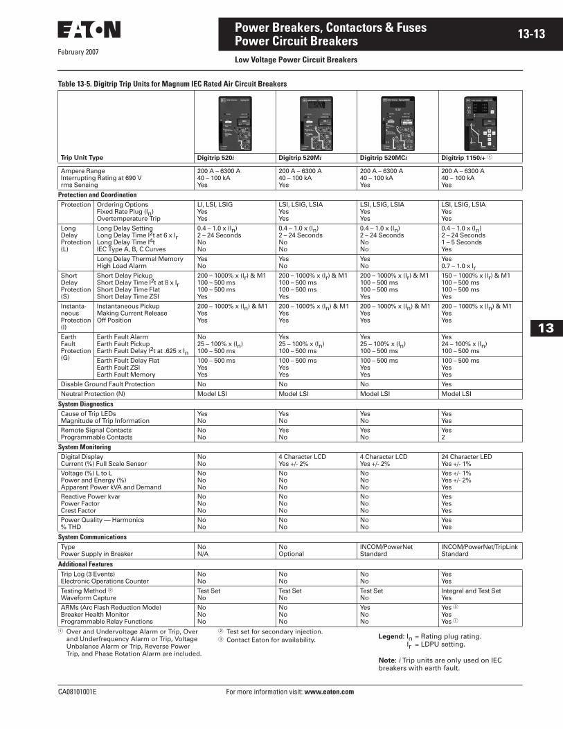
Table 13-5. Digitrip Trip Units for Magnum IEC Rated Air Circuit Breakers
� Over and Undervoltage Alarm or Trip, Over and Underfrequency Alarm or Trip, Voltage Unbalance Alarm or Trip, Reverse Power Trip, and Phase Rotation Alarm are included.
� Test set for secondary injection. � Contact Eaton for availability. Legend: In = Rating plug rating.
Ir = LDPU setting.
Note: i Trip units are only used on IEC breakers with earth fault.
Trip Unit Type Digitrip 520i Digitrip 520Mi Digitrip 520MCi Digitrip 1150i+ �
Ampere RangeInterrupting Rating at 690 Vrms Sensing
200 A – 6300 A40 – 100 kAYes
200 A – 6300 A40 – 100 kAYes
200 A – 6300 A40 – 100 kAYes
200 A – 6300 A40 – 100 kAYes
Protection and CoordinationProtection Ordering Options
Fixed Rate Plug (In)Overtemperature Trip
LI, LSI, LSIGYesYes
LSI, LSIG, LSIAYesYes
LSI, LSIG, LSIAYesYes
LSI, LSIG, LSIAYesYes
LongDelayProtection(L)
Long Delay SettingLong Delay Time I2t at 6 x IrLong Delay Time I4tIEC Type A, B, C Curves
0.4 – 1.0 x (In)2 – 24 SecondsNoNo
0.4 – 1.0 x (In)2 – 24 SecondsNoNo
0.4 – 1.0 x (In)2 – 24 SecondsNoNo
0.4 – 1.0 x (In)2 – 24 Seconds1 – 5 SecondsYes
Long Delay Thermal MemoryHigh Load Alarm
YesNo
YesNo
YesNo
Yes0.7 – 1.0 x Ir
ShortDelayProtection(S)
Short Delay PickupShort Delay Time I2t at 8 x IrShort Delay Time FlatShort Delay Time ZSI
200 – 1000% x (Ir) & M1100 – 500 ms100 – 500 msYes
200 – 1000% x (Ir) & M1100 – 500 ms100 – 500 msYes
200 – 1000% x (Ir) & M1100 – 500 ms100 – 500 msYes
150 – 1000% x (Ir) & M1100 – 500 ms100 – 500 msYes
Instanta-neousProtection(I)
Instantaneous PickupMaking Current ReleaseOff Position
200 – 1000% x (In) & M1Yes Yes
200 – 1000% x (In) & M1Yes Yes
200 – 1000% x (In) & M1Yes Yes
200 – 1000% x (In) & M1Yes Yes
EarthFaultProtection(G)
Earth Fault AlarmEarth Fault PickupEarth Fault Delay I2t at .625 x In
No25 – 100% x (In)100 – 500 ms
Yes25 – 100% x (In)100 – 500 ms
Yes25 – 100% x (In)100 – 500 ms
Yes24 – 100% x (In)100 – 500 ms
Earth Fault Delay FlatEarth Fault ZSIEarth Fault Memory
100 – 500 msYes Yes
100 – 500 msYes Yes
100 – 500 msYes Yes
100 – 500 msYes Yes
Disable Ground Fault Protection No No No Yes
Neutral Protection (N) Model LSI Model LSI Model LSI Model LSI
System DiagnosticsCause of Trip LEDsMagnitude of Trip Information
YesNo
YesNo
YesNo
YesYes
Remote Signal ContactsProgrammable Contacts
NoNo
YesNo
YesNo
Yes2
System MonitoringDigital DisplayCurrent (%) Full Scale Sensor
NoNo
4 Character LCD Yes +/- 2%
4 Character LCD Yes +/- 2%
24 Character LED Yes +/- 1%
Voltage (%) L to LPower and Energy (%)Apparent Power kVA and Demand
NoNoNo
NoNoNo
NoNoNo
Yes +/- 1%Yes +/- 2%Yes
Reactive Power kvarPower FactorCrest Factor
NoNoNo
NoNoNo
NoNoNo
YesYesYes
Power Quality — Harmonics% THD
NoNo
NoNo
NoNo
YesYes
System CommunicationsTypePower Supply in Breaker
NoN/A
NoOptional
INCOM/PowerNetStandard
INCOM/PowerNet/TripLinkStandard
Additional FeaturesTrip Log (3 Events)Electronic Operations Counter
NoNo
NoNo
NoNo
YesYes
Testing Method �Waveform Capture
Test SetNo
Test SetNo
Test SetNo
Integral and Test SetYes
ARMs (Arc Flash Reduction Mode)Breaker Health MonitorProgrammable Relay Functions
NoNoNo
NoNoNo
YesNoNo
Yes �YesYes �
February 2007
13-14
For more information visit: www.eaton.com CA08101001E
Power Breakers, Contactors & Fuses
13
Power Circuit BreakersLow Voltage Power Circuit Breakers
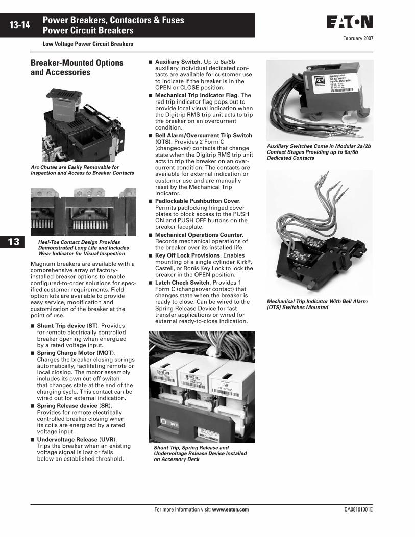
Breaker-Mounted Options and Accessories
Arc Chutes are Easily Removable for
Inspection and Access to Breaker Contacts
Heel-Toe Contact Design Provides
Demonstrated Long Life and Includes
Wear Indicator for Visual Inspection
Magnum breakers are available with a comprehensive array of factory-installed breaker options to enable configured-to-order solutions for spec-ified customer requirements. Field option kits are available to provide easy service, modification and customization of the breaker at the point of use.
■ Shunt Trip device (ST). Provides for remote electrically controlled breaker opening when energized by a rated voltage input.
■ Spring Charge Motor (MOT).Charges the breaker closing springs automatically, facilitating remote or local closing. The motor assembly includes its own cut-off switch that changes state at the end of the charging cycle. This contact can be wired out for external indication.
■ Spring Release device (SR). Provides for remote electrically controlled breaker closing when its coils are energized by a rated voltage input.
■ Undervoltage Release (UVR). Trips the breaker when an existing voltage signal is lost or falls below an established threshold.
■ Auxiliary Switch. Up to 6a/6b auxiliary individual dedicated con-tacts are available for customer use to indicate if the breaker is in the OPEN or CLOSE position.
■ Mechanical Trip Indicator Flag. The red trip indicator flag pops out to provide local visual indication when the Digitrip RMS trip unit acts to trip the breaker on an overcurrent condition.
■ Bell Alarm/Overcurrent Trip Switch (OTS). Provides 2 Form C (changeover) contacts that change state when the Digitrip RMS trip unit acts to trip the breaker on an over-current condition. The contacts are available for external indication or customer use and are manually reset by the Mechanical Trip Indicator.
■ Padlockable Pushbutton Cover.Permits padlocking hinged cover plates to block access to the PUSH ON and PUSH OFF buttons on the breaker faceplate.
■ Mechanical Operations Counter. Records mechanical operations of the breaker over its installed life.
■ Key Off Lock Provisions. Enables mounting of a single cylinder Kirk�, Castell, or Ronis Key Lock to lock the breaker in the OPEN position.
■ Latch Check Switch. Provides 1 Form C (changeover contact) that changes state when the breaker is ready to close. Can be wired to the Spring Release Device for fast transfer applications or wired for external ready-to-close indication.
Shunt Trip, Spring Release and
Undervoltage Release Device Installed
on Accessory Deck
Auxiliary Switches Come in Modular 2a/2b
Contact Stages Providing up to 6a/6b
Dedicated Contacts
Mechanical Trip Indicator With Bell Alarm
(OTS) Switches Mounted
February 2007
CA08101001E For more information visit: www.eaton.com
13-15Power Breakers, Contactors & Fuses
13
Power Circuit BreakersLow Voltage Power Circuit Breakers
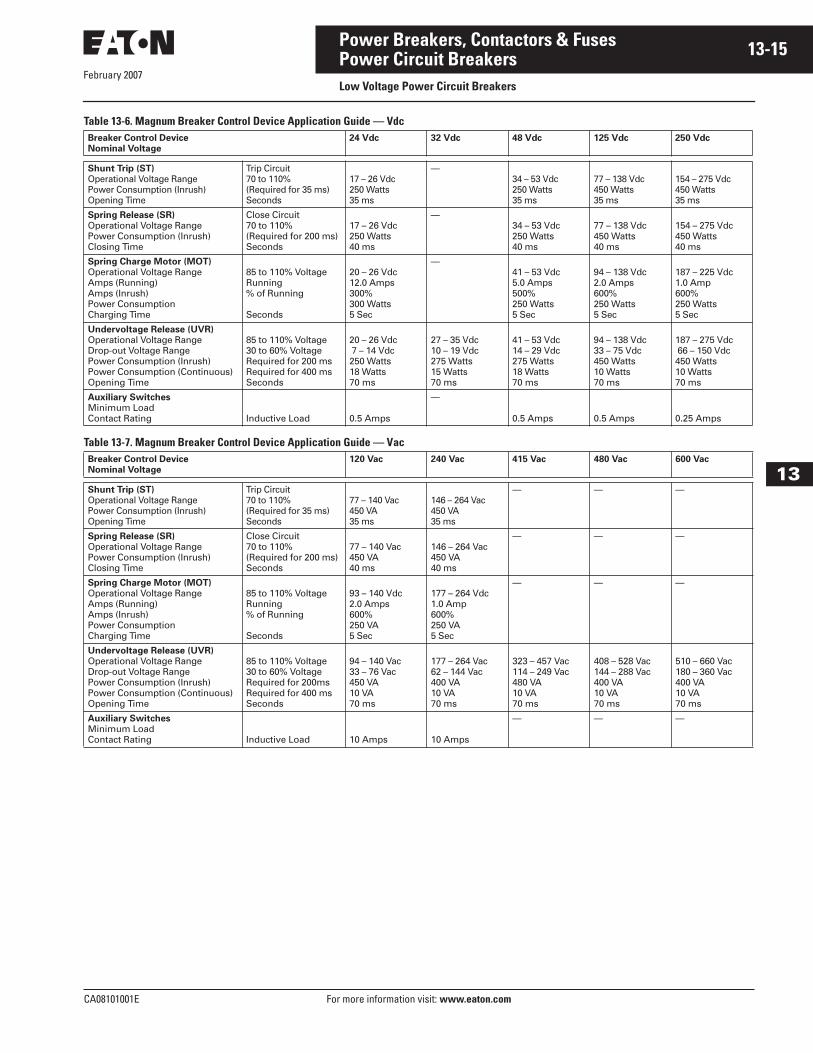
Table 13-6. Magnum Breaker Control Device Application Guide — Vdc
Table 13-7. Magnum Breaker Control Device Application Guide — Vac
Breaker Control Device
Nominal Voltage
24 Vdc 32 Vdc 48 Vdc 125 Vdc 250 Vdc
Shunt Trip (ST)
Operational Voltage Range Power Consumption (Inrush) Opening Time
Trip Circuit70 to 110%(Required for 35 ms)Seconds
17 – 26 Vdc250 Watts35 ms
—34 – 53 Vdc250 Watts35 ms
77 – 138 Vdc450 Watts35 ms
154 – 275 Vdc450 Watts35 ms
Spring Release (SR)
Operational Voltage RangePower Consumption (Inrush) Closing Time
Close Circuit70 to 110%(Required for 200 ms)Seconds
17 – 26 Vdc250 Watts40 ms
—34 – 53 Vdc250 Watts40 ms
77 – 138 Vdc450 Watts40 ms
154 – 275 Vdc450 Watts40 ms
Spring Charge Motor (MOT)
Operational Voltage RangeAmps (Running)Amps (Inrush)Power ConsumptionCharging Time
85 to 110% VoltageRunning% of Running
Seconds
20 – 26 Vdc12.0 Amps300%300 Watts5 Sec
—41 – 53 Vdc5.0 Amps500%250 Watts5 Sec
94 – 138 Vdc2.0 Amps600%250 Watts5 Sec
187 – 225 Vdc1.0 Amp600%250 Watts5 Sec
Undervoltage Release (UVR)
Operational Voltage RangeDrop-out Voltage RangePower Consumption (Inrush)Power Consumption (Continuous)Opening Time
85 to 110% Voltage30 to 60% VoltageRequired for 200 msRequired for 400 msSeconds
20 – 26 Vdc 7 – 14 Vdc250 Watts18 Watts70 ms
27 – 35 Vdc10 – 19 Vdc275 Watts15 Watts70 ms
41 – 53 Vdc14 – 29 Vdc275 Watts18 Watts70 ms
94 – 138 Vdc33 – 75 Vdc450 Watts10 Watts70 ms
187 – 275 Vdc 66 – 150 Vdc450 Watts10 Watts70 ms
Auxiliary Switches
Minimum LoadContact Rating Inductive Load 0.5 Amps
—
0.5 Amps 0.5 Amps 0.25 Amps
Breaker Control Device
Nominal Voltage
120 Vac 240 Vac 415 Vac 480 Vac 600 Vac
Shunt Trip (ST)
Operational Voltage Range Power Consumption (Inrush) Opening Time
Trip Circuit70 to 110%(Required for 35 ms)Seconds
77 – 140 Vac450 VA35 ms
146 – 264 Vac450 VA35 ms
— — —
Spring Release (SR)
Operational Voltage RangePower Consumption (Inrush) Closing Time
Close Circuit70 to 110%(Required for 200 ms)Seconds
77 – 140 Vac450 VA40 ms
146 – 264 Vac450 VA40 ms
— — —
Spring Charge Motor (MOT)
Operational Voltage RangeAmps (Running)Amps (Inrush)Power ConsumptionCharging Time
85 to 110% VoltageRunning% of Running
Seconds
93 – 140 Vdc2.0 Amps600%250 VA5 Sec
177 – 264 Vdc1.0 Amp600%250 VA5 Sec
— — —
Undervoltage Release (UVR)
Operational Voltage RangeDrop-out Voltage RangePower Consumption (Inrush)Power Consumption (Continuous)Opening Time
85 to 110% Voltage30 to 60% VoltageRequired for 200msRequired for 400 msSeconds
94 – 140 Vac33 – 76 Vac450 VA10 VA70 ms
177 – 264 Vac62 – 144 Vac400 VA10 VA70 ms
323 – 457 Vac114 – 249 Vac480 VA10 VA70 ms
408 – 528 Vac144 – 288 Vac400 VA10 VA70 ms
510 – 660 Vac180 – 360 Vac400 VA10 VA70 ms
Auxiliary Switches
Minimum LoadContact Rating Inductive Load 10 Amps 10 Amps
— — —
February 2007
13-16
For more information visit: www.eaton.com CA08101001E
Power Breakers, Contactors & Fuses
13
Power Circuit BreakersLow Voltage Power Circuit Breakers
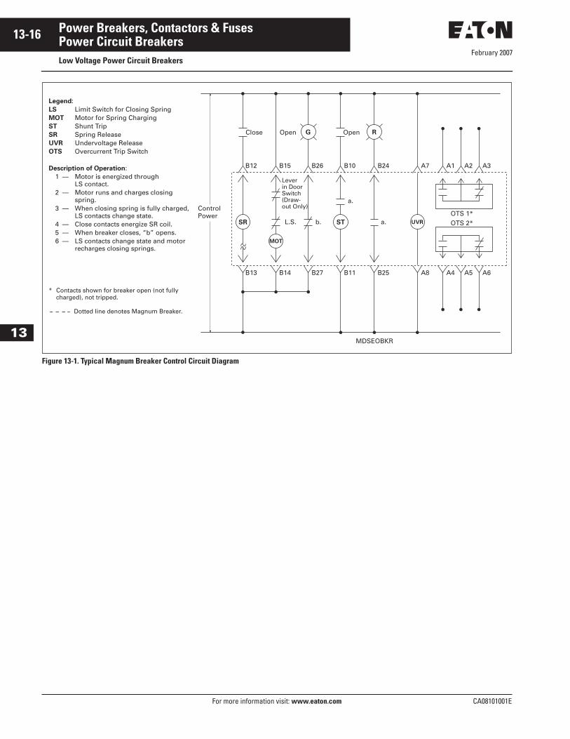
Figure 13-1. Typical Magnum Breaker Control Circuit Diagram
Control Power
Close
B12
Lever in Door Switch (Draw- out Only)
L.S. b.
a.
a.OTS 1*OTS 2*
B15 B26
MDSEOBKR
B10 B24 A7
B13 B14 B27 B11 B25 A8
A1 A2 A3
A4 A5 A6
Open OpenG R
SR
MOT
UVRST
Legend:LS Limit Switch for Closing SpringMOT Motor for Spring ChargingST Shunt TripSR Spring ReleaseUVR Undervoltage ReleaseOTS Overcurrent Trip Switch
Description of Operation:1 — Motor is energized through
LS contact.2 — Motor runs and charges closing
spring.3 — When closing spring is fully charged,
LS contacts change state.4 — Close contacts energize SR coil.5 — When breaker closes, “b” opens.6 — LS contacts change state and motor
recharges closing springs.
* Contacts shown for breaker open (not fullycharged), not tripped.
Dotted line denotes Magnum Breaker.
February 2007
CA08101001E For more information visit: www.eaton.com
13-17Power Breakers, Contactors & Fuses
13
Power Circuit BreakersMedium Voltage Circuit Breakers
Medium Voltage Breakers
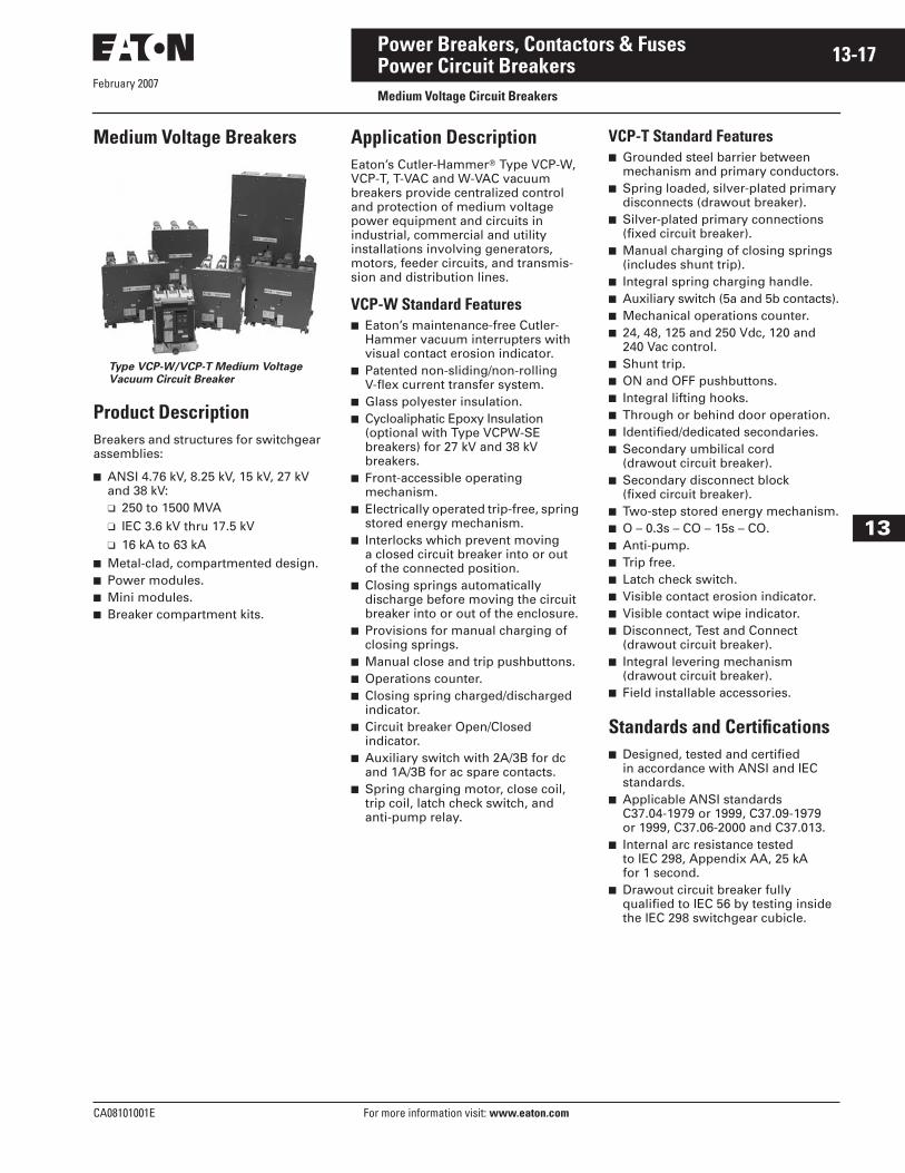
Type VCP-W/VCP-T Medium Voltage
Vacuum Circuit Breaker
Product DescriptionBreakers and structures for switchgear assemblies:
■ ANSI 4.76 kV, 8.25 kV, 15 kV, 27 kV and 38 kV:❑ 250 to 1500 MVA❑ IEC 3.6 kV thru 17.5 kV❑ 16 kA to 63 kA
■ Metal-clad, compartmented design.■ Power modules.■ Mini modules.■ Breaker compartment kits.
Application DescriptionEaton’s Cutler-Hammer� Type VCP-W, VCP-T, T-VAC and W-VAC vacuum breakers provide centralized control and protection of medium voltage power equipment and circuits in industrial, commercial and utility installations involving generators, motors, feeder circuits, and transmis-sion and distribution lines.
VCP-W Standard Features■ Eaton’s maintenance-free Cutler-
Hammer vacuum interrupters with visual contact erosion indicator.
■ Patented non-sliding/non-rolling V-flex current transfer system.
■ Glass polyester insulation.■ Cycloaliphatic Epoxy Insulation
(optional with Type VCPW-SE breakers) for 27 kV and 38 kV breakers.
■ Front-accessible operating mechanism.
■ Electrically operated trip-free, spring stored energy mechanism.
■ Interlocks which prevent moving a closed circuit breaker into or out of the connected position.
■ Closing springs automatically discharge before moving the circuit breaker into or out of the enclosure.
■ Provisions for manual charging of closing springs.
■ Manual close and trip pushbuttons.■ Operations counter.■ Closing spring charged/discharged
indicator.■ Circuit breaker Open/Closed
indicator.■ Auxiliary switch with 2A/3B for dc
and 1A/3B for ac spare contacts.■ Spring charging motor, close coil,
trip coil, latch check switch, and anti-pump relay.
VCP-T Standard Features■ Grounded steel barrier between
mechanism and primary conductors.■ Spring loaded, silver-plated primary
disconnects (drawout breaker).■ Silver-plated primary connections
(fixed circuit breaker).■ Manual charging of closing springs
(includes shunt trip).■ Integral spring charging handle.■ Auxiliary switch (5a and 5b contacts).■ Mechanical operations counter.■ 24, 48, 125 and 250 Vdc, 120 and
240 Vac control.■ Shunt trip.■ ON and OFF pushbuttons.■ Integral lifting hooks.■ Through or behind door operation.■ Identified/dedicated secondaries.■ Secondary umbilical cord
(drawout circuit breaker).■ Secondary disconnect block
(fixed circuit breaker).■ Two-step stored energy mechanism.■ O – 0.3s – CO – 15s – CO.■ Anti-pump.■ Trip free.■ Latch check switch.■ Visible contact erosion indicator.■ Visible contact wipe indicator.■ Disconnect, Test and Connect
(drawout circuit breaker).■ Integral levering mechanism
(drawout circuit breaker).■ Field installable accessories.
Standards and Certifications■ Designed, tested and certified
in accordance with ANSI and IEC standards.
■ Applicable ANSI standards C37.04-1979 or 1999, C37.09-1979 or 1999, C37.06-2000 and C37.013.
■ Internal arc resistance tested to IEC 298, Appendix AA, 25 kAfor 1 second.
■ Drawout circuit breaker fully qualified to IEC 56 by testing inside the IEC 298 switchgear cubicle.
February 2007
13-18
For more information visit: www.eaton.com CA08101001E
Power Breakers, Contactors & Fuses
13
Power Circuit BreakersMedium Voltage Circuit Breakers
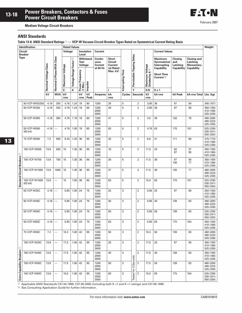
ANSI StandardsTable 13-8. ANSI Standard Ratings � — VCP-W Vacuum Circuit Breaker Types Rated on Symmetrical Current Rating Basis
� Applicable ANSI Standards C37.04-1999, C37.06-2000 (including both K >1 and K =1 ratings) and C37.09-1999.� See Consulting Application Guide for further information.
Identification Rated Values Weight
CircuitBreakerType
No
min
al V
olt
ag
e C
lass
No
min
al 3-P
hase M
VA
Cla
ss
Voltage Insulation Level
Current
Inte
rru
pti
ng
Tim
e
Perm
issib
le T
rip
pin
g D
ela
y
Maxim
um
Vo
ltag
e
Div
ided
by K
�
Current Values
Maxim
um
Vo
ltag
e
Vo
ltag
e R
an
ge F
acto
r � Withstand
Test Voltage
Contin-uous Current at 60 Hz
Short Circuit Current (at Rated Max. kV)
MaximumSymmetricalInterruptingCapability
Short TimeCurrent �
ClosingandLatchingCapability
Closing andLatchingMomentaryCapability
Po
wer
Fre
qu
en
cy
(1 M
in.)
Imp
uls
eE K I Y E/K K x 1
kV MVA kV rms
kV rms
kV Peak
Amperes kA rms
Cycles Seconds kV rms
kA rms kA Peak kA rms Total Lbs. (kg)
Sta
nd
ard
Cir
cu
it B
reakers
�
50 VCP-WND250 4.16 250 4.76 1.24 19 60 1200 29 5 2 3.85 36 97 58 345 (157)
50 VCP-W250 4.16 250 4.76 1.24 19 60 120020003000
29 5 2 3.85 36 97 58 350 (159)410 (186)525 (238)
50 VCP-W350 4.16 350 4.76 1.19 19 60 120020003000
41 5 2 4.0 49 132 78 460 (209)490 (223)525 (238)
50 VCP-W500(63 kA)
4.16 — 4.76 1.00 19 60 120020003000
63 5 2 4.76 63 170 101 525 (238)530 (241)550 (250)
75 VCP-W500 7.2 500 8.25 1.25 36 95 120020003000
33 5 2 6.6 41 111 66 375 (170)410 (186)525 (238)
150 VCP-W500 13.8 500 15 1.30 36 95 120020003000
18 5 2 11.5 23 62 97
37 58
350 (159)410 (186)525 (238)
150 VCP-W750 13.8 750 15 1.30 36 95 120020003000
28 5 2 11.5 36 97130
58 77
350 (159)410 (186)525 (238)
150 VCP-W1000 13.8 1000 15 1.30 36 95 120020003000
37 5 2 11.5 48 130 77 460 (209)490 (223)525 (238)
150 VCP-W1500(63 kA)
13.8 — 15 1.00 36 95 120020003000
63 5 2 15.0 63 170 101 525 (238)530 (241)550 (250)
Extr
a C
ap
ab
ilit
y B
reakers
�
50 VCP-W25C 4.16 — 5.95 1.00 24 75 120020003000
25 3
Test
ed fo
r 3
Sec
onds
2 5.95 25 97 58 350 (159)410 (186)525 (238)
50 VCP-W40C 4.16 — 5.95 1.00 24 75 120020003000
40 3 2 5.95 40 139 83 460 (209)490 (223)525 (238)
50 VCP-W50C 4.16 — 5.95 1.00 24 75 120020003000
50 3 2 5.95 50 139 83 525 (238)530 (241)550 (250)
50 VCP-W63C 4.16 — 5.95 1.00 24 75 120020003000
63 3 2 5.95 63 175 104 350 (159)410 (186)525 (238)
75 VCP-W50C 7.2 — 10.3 1.00 42 95 120020003000
50 3 2 10.3 50 139 83 460 (209)490 (223)525 (238)
150 VCP-W25C 13.8 — 17.5 1.00 42 95 120020003000
25 3 2 17.5 25 97 58 350 (159)410 (186)525 (238)
150 VCP-W40C 13.8 — 17.5 1.00 42 95 120020003000
40 3 2 17.5 40 139 83 350 (159)410 (186)525 (238)
150 VCP-W50C 13.8 — 17.5 1.00 42 95 120020003000
50 3 2 17.5 50 139 83 460 (209)490 (223)525 (238)
150 VCP-W63C 13.8 — 15.0 1.00 42 95 120020003000
63 3 2 15.0 63 175 104 525 (238)530 (241)550 (250)

February 2007
CA08101001E For more information visit: www.eaton.com
13-19Power Breakers, Contactors & Fuses
13
Power Circuit BreakersMedium Voltage Circuit Breakers
Table 13-8. ANSI Standards � — VCP-W Vacuum Circuit Breaker Types Rated on Symmetrical Current Rating Basis (Continued)
� Applicable ANSI Standards C37.04-1999, C37.06-2000 (including both K >1 and K =1 ratings), and C37.09-1999.� See Consulting Application Guide for further information.
Identification Rated Values Weight
CircuitBreakerType
No
min
al V
olt
ag
e C
lass
No
min
al 3-P
hase M
VA
Cla
ss
Voltage Insulation Level
Current
Inte
rru
pti
ng
Tim
e
Perm
issib
le T
rip
pin
g D
ela
y
Maxim
um
Vo
ltag
e �
D
ivid
ed
by K
Current Values
Maxim
um
Vo
ltag
e
Vo
ltag
e R
an
ge F
acto
r� Withstand Test Voltage
Contin-uous Current at 60 Hz
Short Circuit Current (at Rated Max. kV)
MaximumSymmetricalInterruptingCapability
Short TimeCurrent �
ClosingandLatchingCapability
Closing andLatchingMomentaryCapability
Po
wer
Fre
qu
en
cy
(1 M
in.)
Imp
uls
e
E K I Y E/K K x 1
kV MVA kV rms
kV rms
kV Peak
Amperes kA rms
Cycles Seconds kV rms
kA rms kA Peak kA rms Total Lbs. (kg)
Gen
erat
or B
reak
ers
(to
AN
SI C
37.0
13) 50 VCP-WG50 4.16 — 4.76 1.00 19 60 1200
20003000
50 3
Test
ed fo
r 3
Sec
onds
1 4.76 50 137 82 525 (238)530 (241)550 (250
50 VCP-WG63 4.16 — 4.76 1.00 19 60 120020003000
63 3 1 4.76 63 173 103 525 (238)530 (241)550 (250
150 VCP-WG50 13.8 — 15.0 1.00 36 95 120020003000
50 3 1 15.0 50 137 82 525 (238)530 (241)550 (250)
150 VCP-WG63 13.8 — 15.0 1.00 36 95 120020003000
63 3 1 15.0 63 173 103 525 (238)530 (241)550 (250)

February 2007
13-20
For more information visit: www.eaton.com CA08101001E
Power Breakers, Contactors & Fuses
13
Power Circuit BreakersMedium Voltage Circuit Breakers
Table 13-9. VCP-W Vacuum Breaker Types rated on Symmetrical Current Rating Basis �
� CESI tested to applicable ANSI standards C37.04, C37.09 and C37.06. Consult Eaton for CESI copies of test reports on file. Operating duty cycle CO-15 seconds-CO. Operating time values: Opening 33 – 55 ms, closing 50 – 60 ms and reclosing 18 cycles (300 ms).
� Tested at 28.5 kV.� K = 1.0, therefore E = E/K and I = KI.� Also maximum interrupting rating and short-time current rating.� Duration of short-time current = 3 seconds, except as noted in � Optional interrupting time of 50 ms (3 cycles) is available.
Identification Rated Values Weight
Circuit
Breaker
Type
No
min
al
Vo
ltag
e C
lass
No
min
al 3-P
hase
MV
A C
lass
Voltage Insulation
Level
Current
Inte
rru
pti
ng
Tim
e
Maxim
um
Perm
issib
le
Tri
pp
ing
Dela
y Y
Transient
Recovery
Voltage
Current
Values
Maxim
um
Vo
ltag
e
E Vo
ltag
e R
an
ge
Facto
r �
K
Withstand
Test Voltage
Co
nti
nu
ou
s C
urr
en
t
at
60 H
z
Sh
ort
Cir
cu
it C
urr
en
t
(at
Rate
d m
ax. kV
) I
��
E2 T2
Clo
sin
g a
nd
Latc
hin
g C
ap
ab
ilit
y
(2.6
K T
imes
Rate
d S
ho
rt C
ircu
it
Cu
rren
t)
Cap
acit
or
Sw
itch
ing
Cab
le C
harg
ing
Po
wer
Fre
qu
en
cy
(1 m
in.)
Imp
uls
e
kV MVA kV rms kV rms kV Peak Amperes kA rms ms (Cy) Seconds kV Peak µs kA Peak Amperes lbs.
270 VCP-W750 27 750 27 � 1.0 60 125 60012002000
16 83 (5) � 2 51 105 ¥43 31.5 460480500
270 VCP-W1000 27 1000 27 � 1.0 60 125 60012002000
22 83 (5) � 2 51 105 60 31.5 460480500
270 VCP-W1250 27 1250 27 � 1.0 60 125 60012002000
25 83 (5) � 2 51 105 68 31.5 460480500
270 VCP-W1600 27 1600 27 � 1.0 60 125 12002000
25 83 (5) � 2 51 105 85 31.5 545560
270 VCP-W2000 27 2000 27 � 1.0 60 125 12002000
40 83 (5) � 2 51 105 106 31.5 545600
270 VCP-W25C 27 — 27 1.0 60 125 12001600
25 50 (3) 2.5 50 50 85 31.5 545560
270 VCP-W32C 27 — 27 1.0 60 125 12001600
31.5 50 (3) 1.6 50 50 100 31.5 545560
270 VCP-W40C 27 — 27 1.0 60 125 12001600
40 50 (3) 1.0 50 50 112 31.5 545560
February 2007
CA08101001E For more information visit: www.eaton.com
13-21Power Breakers, Contactors & Fuses
13
Power Circuit BreakersMedium Voltage Circuit Breakers
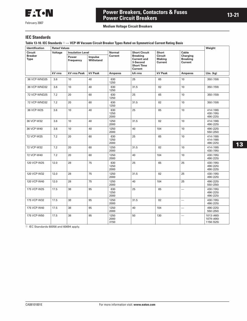
IEC StandardsTable 13-10. IEC Standards � — VCP-W Vacuum Circuit Breaker Types Rated on Symmetrical Current Rating Basis
� IEC Standards 60056 and 60694 apply.
Identification Rated Values Weight
Circuit
Breaker
Type
Voltage Insulation Level Normal
Current
Short Circuit
Breaking
Current and
3-Second
Short Time
Current
Short
Circuit
Making
Current
Cable
Charging
Breaking
Current
Power
Frequency
Impulse
Withstand
kV rms kV rms Peak kV Peak Amperes kA rms kV Peak Amperes Lbs. (kg)
36 VCP-WND25 3.6 10 40 6301250
25 65 10 350 (159)
36 VCP-WND32 3.6 10 40 6301250
31.5 82 10 350 (159)
72 VCP-WND25 7.2 20 60 6301250
25 65 10 350 (159)
72 VCP-WND32 7.2 20 60 6301250
31.5 82 10 350 (159)
36 VCP-W25 3.6 10 40 63012502000
25 65 10 414 (188) 430 (195) 496 (225)
36 VCP-W32 3.6 10 40 12502000
31.5 82 10 414 (188) 496 (225)
36 VCP-W40 3.6 10 40 12502000
40 104 10 496 (225) 550 (250)
72 VCP-W25 7.2 20 60 63012502000
25 65 10 414 (188) 414 (188) 496 (225)
72 VCP-W32 7.2 20 60 12502000
31.5 82 10 414 (188) 430 (195)
72 VCP-W40 7.2 20 60 12502000
40 104 10 430 (195) 496 (225)
120 VCP-W25 12.0 28 75 63012502000
25 65 25 430 (195) 496 (225) 496 (225)
120 VCP-W32 12.0 28 75 12502000
31.5 82 25 430 (195) 496 (225)
120 VCP-W40 12.0 28 75 12502000
40 104 25 496 (225) 550 (250)
175 VCP-W25 17.5 38 95 63012502000
25 65 — 430 (195) 496 (225) 496 (225)
175 VCP-W32 17.5 38 95 12502000
31.5 82 — 430 (195) 496 (225)
175 VCP-W40 17.5 38 95 12502000
40 104 — 496 (225) 550 (250)
175 VCP-W50 17.5 38 95 125020003150
50 130 — 1013 (460)1079 (490)1156 (525)
February 2007
13-22
For more information visit: www.eaton.com CA08101001E
Power Breakers, Contactors & Fuses
13
Power Circuit BreakersMedium Voltage Circuit Breakers
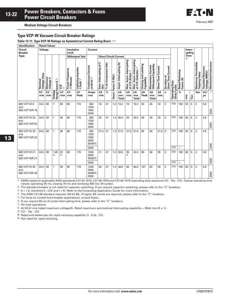
Type VCP-W Vacuum Circuit Breaker RatingsTable 13-11. Type VCP-W Ratings on Symmetrical Current Rating Basis ��
� KEMA tested to applicable ANSI standards C37.04-1979, C37.09-1979 and C37.06-1979 (operating duty sequence CO - 15s - CO). Typical operating time values: operating 45 ms, closing 75 ms and reclosing 300 ms (18 cycles).
� The standard breaker is not rated for capacitor switching. If you require capacitor switching, please refer to the “C” breakers.� K = 1.0, therefore E = E/K and I = KI. Refer to the Consulting Application Guide for more information.� The ANSI C37.06 standard requires 150 kV BIL. If higher BIL levels are required, please refer to the “C” breakers.� For force air cooled fixed breaker applications, consult Eaton.� If you require 50 ms (3 cycle) interrupting time, please refer to the “C” breakers.� No-load operations. At 23 kV rms (rated maximum voltage/K). Rated maximum symmetrical interrupting capability = 35kA rms (K x 1). CO – 15s – CO.� Rated and tested also for rapid reclosing capability O - 0.3s - CO.� Not rated for rapid reclosing.
Identification Rated Values
Circuit
Breaker
Type
Voltage Insulation Level
Current
Op
era
tin
g D
uty
(Du
ty C
ycle
)
Rate
d R
eclo
sin
gFacto
r (R
)
Interr-uptingTime�
Maxim
um
Perm
issib
leTri
pp
ing
Dela
y
Tra
nsie
nt
Reco
very
Vo
ltag
e (R
RR
V)
Mech
an
ical E
nd
ura
nce
No
min
al
Vo
ltag
e C
lass
Maxim
um
Vo
ltag
e V
Vo
ltag
eR
an
ge F
acto
r K
�
V/K
�
Withstand Test
Co
nti
nu
ou
s C
urr
en
tat
60 H
z �
Short Circuit Current
Po
wer
Fre
qu
en
cy
(1 M
inu
te)
Lig
htn
ing
Im
pu
lse
1.2
x50 �
Sym
. In
terr
up
tin
g a
t V
(Isc)
% d
c C
om
po
nen
t (I
dc)
Asym
. Facto
r S
(R
ef.
)
Asym
. In
terr
up
tin
g (It
)
Max. A
sym
. In
terr
up
tin
gat
V/K
(K
xls
c)
�
Max. A
sym
. In
terr
up
tin
gat
V/K
(S
xK
xls
c)
�
Clo
sin
g a
nd
Latc
hin
gC
ap
ab
ilit
y
Mo
men
tary
Cu
rren
tW
ith
sta
nd
Cap
ab
ilit
y
Sh
ort
Tim
e C
urr
en
t
Du
rati
on
of
Sh
ort
Tim
e C
urr
en
t
kV
rms
kV
rms
kV
rms
kV
rms
kV
Peak
Amps
rms
kA
rms
% kA
rms
Total
kA
rms
kA
rms
Total
kA
Peak
kA
rms
Total
kA
rms
s %
rms
Cyc.
Sec. kV/
µs
�
380 VCP-W 6and380 VCP-WR 16
34.5 38 1 38 80 170 600120016002000
16 47 1.2 19.2 16 19.3 43 26 16 3 � 100 83 5 2 0.6
2000
380 VCP-W 25and380 VCP-WR 25
34.5 38 1 38 80 170 600120016002000
25 47 1.2 30.0 25 30.0 68 40 25 3 � 100 83 5 2 0.6
2000
380 VCP-W 32and380 VCP-WR 32
34.5 38 1 38 80 170 6001200160020003000FC
31.5 47 1.2 37.8 31.5 37.8 85 50 31.5 3 � 100 83 5 2 0.6
2000
2500 � —
380 VCP-W 21and380 VCP-WR 21
34.5 38 1.65
23
80 170 120020003000FC
21 47 1.2 39.5 35
42.0 95 56 35 3 � 100 83 5 2 0.6
2000
2500 � —
380 VCP-W 40and380 VCP-WR 40
34.5 38 1 38 80 170 120020003000FC2500
40 47 1.2 48.0 40 48.0 107 63 40 3 � 100 83 5 2 0.6
2000
February 2007
CA08101001E For more information visit: www.eaton.com
13-23Power Breakers, Contactors & Fuses
13
Power Circuit BreakersMedium Voltage Circuit Breakers
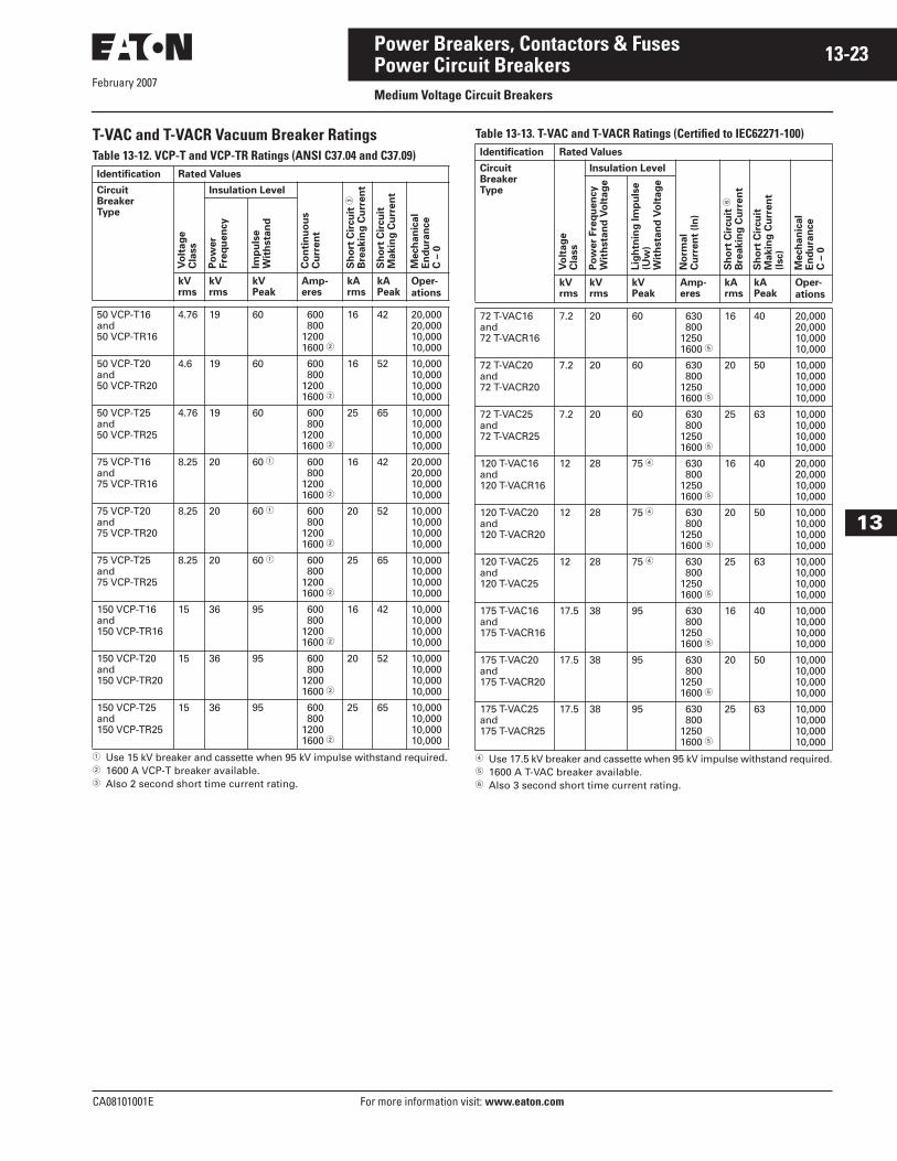
T-VAC and T-VACR Vacuum Breaker RatingsTable 13-12. VCP-T and VCP-TR Ratings (ANSI C37.04 and C37.09)
� Use 15 kV breaker and cassette when 95 kV impulse withstand required.� 1600 A VCP-T breaker available.� Also 2 second short time current rating.
Table 13-13. T-VAC and T-VACR Ratings (Certified to IEC62271-100)
� Use 17.5 kV breaker and cassette when 95 kV impulse withstand required.� 1600 A T-VAC breaker available.� Also 3 second short time current rating.
Identification Rated Values
CircuitBreakerType
Vo
ltag
eC
lass
Insulation Level
Co
nti
nu
ou
sC
urr
en
t
Sh
ort
Cir
cu
it �
Bre
akin
g C
urr
en
t
Sh
ort
Cir
cu
itM
akin
g C
urr
en
t
Mech
an
ical
En
du
ran
ce
C –
0
Po
wer
Fre
qu
en
cy
Imp
uls
eW
ith
sta
nd
kVrms
kVrms
kVPeak
Amp-eres
kArms
kAPeak
Oper-
ations
50 VCP-T16and50 VCP-TR16
4.76 19 60 600 80012001600 �
16 42 20,00020,00010,00010,000
50 VCP-T20and50 VCP-TR20
4.6 19 60 600 80012001600 �
16 52 10,00010,00010,00010,000
50 VCP-T25and50 VCP-TR25
4.76 19 60 600 80012001600 �
25 65 10,00010,00010,00010,000
75 VCP-T16and75 VCP-TR16
8.25 20 60 � 600 80012001600 �
16 42 20,00020,00010,00010,000
75 VCP-T20and 75 VCP-TR20
8.25 20 60 � 600 80012001600 �
20 52 10,00010,00010,00010,000
75 VCP-T25and75 VCP-TR25
8.25 20 60 � 600 80012001600 �
25 65 10,00010,00010,00010,000
150 VCP-T16and150 VCP-TR16
15 36 95 600 80012001600 �
16 42 10,00010,00010,00010,000
150 VCP-T20and150 VCP-TR20
15 36 95 600 80012001600 �
20 52 10,00010,00010,00010,000
150 VCP-T25and150 VCP-TR25
15 36 95 600 80012001600 �
25 65 10,00010,00010,00010,000
Identification Rated Values
CircuitBreakerType
Vo
ltag
eC
lass
Insulation Level
No
rmal
Cu
rren
t (I
n)
Sh
ort
Cir
cu
it �
Bre
akin
g C
urr
en
t
Sh
ort
Cir
cu
itM
akin
g C
urr
en
t(I
sc)
Mech
an
ical
En
du
ran
ce
C –
0
Po
wer
Fre
qu
en
cy
Wit
hsta
nd
Vo
ltag
e
Lig
htn
ing
Im
pu
lse
(Uw
)W
ith
sta
nd
Vo
ltag
e
kVrms
kVrms
kVPeak
Amp-eres
kArms
kAPeak
Oper-
ations
72 T-VAC16and72 T-VACR16
7.2 20 60 630 80012501600 �
16 40 20,00020,00010,00010,000
72 T-VAC20and72 T-VACR20
7.2 20 60 630 80012501600 �
20 50 10,00010,00010,00010,000
72 T-VAC25and72 T-VACR25
7.2 20 60 630 80012501600 �
25 63 10,00010,00010,00010,000
120 T-VAC16and120 T-VACR16
12 28 75 � 630 80012501600 �
16 40 20,00020,00010,00010,000
120 T-VAC20and120 T-VACR20
12 28 75 � 630 80012501600 �
20 50 10,00010,00010,00010,000
120 T-VAC25and120 T-VAC25
12 28 75 � 630 80012501600 �
25 63 10,00010,00010,00010,000
175 T-VAC16and175 T-VACR16
17.5 38 95 630 80012501600 �
16 40 10,00010,00010,00010,000
175 T-VAC20and175 T-VACR20
17.5 38 95 630 80012501600 �
20 50 10,00010,00010,00010,000
175 T-VAC25and175 T-VACR25
17.5 38 95 630 80012501600 �
25 63 10,00010,00010,00010,000

February 2007
13-24
For more information visit: www.eaton.com CA08101001E
Power Breakers, Contactors & Fuses
13
Power Circuit BreakersMedium Voltage Circuit Breakers
Technical Data and Specifications
Mini Module Type VCP-W Circuit Breaker
Shown from Rear
VCP-W Circuit Breaker with Deadfront
Panel Removed
5/15 kV VCPW-ND and VCP-W Power Modules — Dimensions in Inches (mm)
Figure 13-2. Power Module, 5/15 kV VCPW-ND 26.00 (660) Wide, VCP-W 36.00 (914) Wide� VCPW-ND Dimensions of Breaker Travel 15.00 (381.0 mm).
�

February 2007
CA08101001E For more information visit: www.eaton.com
13-25Power Breakers, Contactors & Fuses
13
Power Circuit BreakersMedium Voltage Circuit Breakers
5/15 kV VCPW-ND and VCP-W Mini Modules — Dimensions in Inches (mm)
Figure 13-3. 5 kV VCPW-ND Mini Module 25.88 (657) Wide� Current transformers not supplied.
5/15 kV VCP-W Mini Module — Dimensions in Inches (mm)
Figure 13-4. 5/15 kV VCP-W Mini-Module 35.88 (911) Wide� Current transformers not supplied.
�
�

February 2007
13-26
For more information visit: www.eaton.com CA08101001E
Power Breakers, Contactors & Fuses
13
Power ContactorsProduct Description
SL MV Power Contactor Size 160 – 400 Amperes
SL Medium Voltage Contactor
Product Description■ A single family of contactors for any
medium voltage control application. Voltage range of 2200 to 7200 volts.
■ Ampere ratings from 160 through 400 amperes with Induction Motor Horsepower ranges from 600 to 5500 hp.
■ Three different altitude versions. ■ Leading-edge vacuum technology.■ Fully complies with global
standards.■ Third-party qualified by UL,
CSA, KEMA. ■ Long life — 300,000 electrical
and over 2 million mechanical.■ Mounting flexibility — panel or
pedestal mounting provisions are standard. Unit can be mounted in horizontal or vertical position.
■ Field-selectable settings for coil voltage, ac/dc, and coil dropout time.
■ Field kits available for auxiliary contacts and mechanical latch. Accessories are common for all sizes.
■ Special ordering allows unit to be factory pre-set to customer specification, including field kit installation.
■ Highest quality available — all contactors manufactured within state-of-the-art “ISO-Certified” facilities. 100% made in America.
Application DescriptionEaton’s Cutler-Hammer SL Medium Voltage Contactor starting applications: ■ Squirrel-cage induction motors.■ Synchronous motors.■ Wound-rotor.
Fully applicable to: ■ Full voltage starting.■ Reduced voltage starting.
The perfect choice for harsh duty applications:■ Mining.■ Pulp and paper.■ HVAC.■ Petrochemical.■ Automotive.■ Many others.
Features, Benefits and Functions The SL Contactor Ratings■ Voltages of 2200 – 7200 volts. ■ Amperages from 160 – 400 amperes. ■ Interrupting ratings as high as
8500 amperes.
Control Voltages (Field Adjustable)■ 110, 220 Vac 50 Hz.■ 120, 240 Vac 60 Hz.■ 125 Vdc.
Drop-out Time (Field Adjustable)■ 30 ms■ 50 ms■ 130 ms■ 250 ms■ 330 ms
Global Acceptability ■ NEMA ■ ANSI■ IEC
Third-Party Verification■ UL■ CSA■ KEMA
Easy-to-Install Option Kits (Field Addition)■ Up to 6 extra auxiliary contacts.■ Mechanical latch — many coil
voltages.
Long Life Guarantees High Quality■ 300,000 electrical operations.■ 2.5 million mechanical operations.
Standards and Certifications
Design and Test Standards■ UL 347, File No. E63257.■ CSA T.I.L. D-21, File No. LR28548.■ IEC No. 60470.■ ANSI/NEMA ICS 3 – 1993 (R2000)
Options and Accessories
SL Series — Accessory Kits
Mechanical Latch Kit — SL Vacuum Contactor Sizes 160 – 400 AmperesField Mount to 160 – 400 amperes SL Vacuum Contactor. Coil voltages available in a wide range of ac and dc selections. Easy to install on new and existing units.
Mechanical Latch Kit
Auxiliary Contact Kit — SL Vacuum Contactor Sizes 160 – 400 AmperesField Mount auxiliary contact kits for 160 – 400 amperes SL Vacuum Contactor. Contact kits are available in many configurations of NO-NC.
Auxiliary Contact Kit
Mechanical Interlock KitField Mount mechanical interlock kits for 160 – 400 amperes SL Vacuum Contactor.
Mechanical Interlock Kit
February 2007
CA08101001E For more information visit: www.eaton.com
13-27Power Breakers, Contactors & Fuses
13
Power ContactorsProduct Description
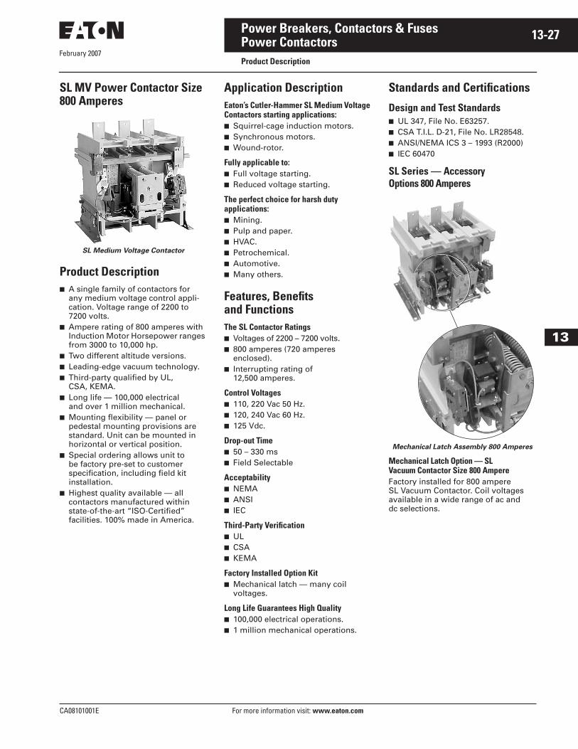
SL MV Power Contactor Size 800 Amperes
SL Medium Voltage Contactor
Product Description■ A single family of contactors for
any medium voltage control appli-cation. Voltage range of 2200 to 7200 volts.
■ Ampere rating of 800 amperes with Induction Motor Horsepower ranges from 3000 to 10,000 hp.
■ Two different altitude versions. ■ Leading-edge vacuum technology.■ Third-party qualified by UL,
CSA, KEMA. ■ Long life — 100,000 electrical
and over 1 million mechanical.■ Mounting flexibility — panel or
pedestal mounting provisions are standard. Unit can be mounted in horizontal or vertical position.
■ Special ordering allows unit to be factory pre-set to customer specification, including field kit installation.
■ Highest quality available — all contactors manufactured within state-of-the-art “ISO-Certified” facilities. 100% made in America.
Application DescriptionEaton’s Cutler-Hammer SL Medium Voltage Contactors starting applications: ■ Squirrel-cage induction motors.■ Synchronous motors.■ Wound-rotor.
Fully applicable to: ■ Full voltage starting.■ Reduced voltage starting.
The perfect choice for harsh duty applications:■ Mining.■ Pulp and paper.■ HVAC.■ Petrochemical.■ Automotive.■ Many others.
Features, Benefits and Functions The SL Contactor Ratings■ Voltages of 2200 – 7200 volts. ■ 800 amperes (720 amperes
enclosed). ■ Interrupting rating of
12,500 amperes.
Control Voltages■ 110, 220 Vac 50 Hz.■ 120, 240 Vac 60 Hz.■ 125 Vdc.
Drop-out Time■ 50 – 330 ms■ Field Selectable
Acceptability ■ NEMA ■ ANSI■ IEC
Third-Party Verification■ UL■ CSA■ KEMA
Factory Installed Option Kit■ Mechanical latch — many coil
voltages.
Long Life Guarantees High Quality■ 100,000 electrical operations.■ 1 million mechanical operations.
Standards and Certifications
Design and Test Standards■ UL 347, File No. E63257.■ CSA T.I.L. D-21, File No. LR28548.■ ANSI/NEMA ICS 3 – 1993 (R2000)■ IEC 60470
SL Series — Accessory Options 800 Amperes
Mechanical Latch Assembly 800 Amperes
Mechanical Latch Option — SL Vacuum Contactor Size 800 AmpereFactory installed for 800 ampere SL Vacuum Contactor. Coil voltages available in a wide range of ac and dc selections.

February 2007
13-28
For more information visit: www.eaton.com CA08101001E
Power Breakers, Contactors & Fuses
13
Power ContactorsSL Series Fuses
SL Series FusesTable 13-14. Fuse Application Table for SL Contactors
� For FLA > 180, maximum acceleration time = 4.5 seconds.
Fuse Application Table for SL Contactors (Continued)
� For FLA > 360, maximum acceleration time = 6 seconds.Note: Fuse selections based on LRC = FLA x 6 with acceleration time of 10 seconds except where otherwise noted.
Motor
FLA
Voltage Suggested
Cutler-Hammer
Fuse
Rating Minimum
Opening
Time
SL-160 11 – 18 18 – 31 31 – 46 46 – 62 62 – 74 74 – 93 93 – 137137 – 160
2400 – 4800 5BCLS-305BCLS-2R5BCLS-3R5BCLS-4R5BCLS-5R5BCLS-6R5BCLS-9R5BCLS-12R
30 – 1R 70 – 2R100 – 3R130 – 4R150 – 5R170 – 6R200 – 9R230 – 12R
30 30 30 30 30 30130130
11 – 34 34 – 46 46 – 56 56 – 68 68 – 85 85 – 137137 – 160
5500 – 6600 7BCLS-2R7BCLS-3R7BCLS-4R7BCLS-5R7BCLS-6R7BCLS-9R7BCLS-12R
70 – 2R100 – 3R130 – 4R150 – 5R170 – 6R200 – 9R230 – 12R
30 30 30 30 30 50250
SL-200 11 – 18 18 – 31 31 – 46 46 – 62 62 – 74 74 – 93 93 – 137137 – 200 �
2400 – 4800 5BCLS-305BCLS-2R5BCLS-3R5BCLS-4R5BCLS-5R5BCLS-6R5BCLS-9R5BCLS-12R
30 – 1R 70 – 2R100 – 3R130 – 4R150 – 5R170 – 6R200 – 9R230 – 12R
30 30 30 30 30 30130130
11 – 34 34 – 46 46 – 56 56 – 68 68 – 85 85 – 137137 – 200 �
5500 – 6600 7BCLS-2R7BCLS-3R7BCLS-4R7BCLS-5R7BCLS-6R7BCLS-9R7BCLS-12R
70 – 2R100 – 3R130 – 4R150 – 5R170 – 6R200 – 9R230 – 12R
30 30 30 30 30 50250
Motor
FLA
Voltage Suggested
Cutler-Hammer
Fuse
Rating Minimum
Opening
Time
SL-360 11 – 18 18 – 31 31 – 46 46 – 62 62 – 74 74 – 93 93 – 137137 – 187187 – 200200 – 360
2400 – 4800 5BCLS-305BCLS-2R5BCLS-3R5BCLS-4R5BCLS-5R5BCLS-6R5BCLS-9R5BCLS-12R5BCLS-12RN/A
30 – 1R 70 – 2R100 – 3R130 – 4R150 – 5R170 – 6R200 – 9R230 – 12R230 – 12R—
30 30 30 30 30 30130130130—
11 – 34 34 – 46 46 – 56 56 – 68 68 – 85 85 – 137137 – 200187 – 200200 – 360
5500 – 6600 7BCLS-2R7BCLS-3R7BCLS-4R7BCLS-5R7BCLS-6R7BCLS-9R7BCLS-12R7BCLS-12RN/A
70 – 2R100 – 3R130 – 4R150 – 5R170 – 6R200 – 9R230 – 12R230 – 12R—
30 30 30 30 30 50250250—
SL-400 11 – 18 18 – 31 31 – 46 46 – 62 62 – 74 74 – 93 93 – 137137 – 187187 – 273273 – 400 �
2400 – 4800 5BCLS-305BCLS-2R5BCLS-3R5BCLS-4R5BCLS-5R5BCLS-6R5BCLS-9R5BCLS-12R5BCLS-18R5BCLS-24R
30 – 1R 70 – 2R100 – 3R130 – 4R150 – 5R170 – 6R200 – 9R230 – 12R390 – 18R450 – 24R
30 30 30 30 30 30 30 30 50130
11 – 34 34 – 46 46 – 56 56 – 68 68 – 85 85 – 137137 – 187187 – 273273 – 400 �
5500 – 6600 7BCLS-2R7BCLS-3R7BCLS-4R7BCLS-5R7BCLS-6R7BCLS-9R7BCLS-12R7BCLS-18R7BCLS-24R
70 – 2R100 – 3R130 – 4R150 – 5R170 – 6R200 – 9R230 – 12R390 – 18R450 – 24R
30 30 30 30 30 30 30 50250
SL-800 225 – 360 360 – 449 450 – 720
2400 – 4800 5BCLS-24R5BCLS-36R5BCLS-44R
450 – 24R650 – 36R800 – 44R
50130250
225 – 400 400 – 449 450 – 720
5500 – 6600 7BCLS-24R7BCLS-36R7BCLS-44R
450 – 24R650 – 36R800 – 44R
50130250

February 2007
CA08101001E For more information visit: www.eaton.com
13-29Power Breakers, Contactors & Fuses
13
Power ContactorsSL Series Ratings
SL Series RatingsTable 13-15. Type SL Vacuum Contactor Ratings
Table 13-16. Rating Specifications
Rated
Utilization
Voltage
Interrupting Rating Application Table Transformer
kVA
Capacitor
kvar
Maximum
Insulation
VoltageNEMA
Unfused (E1)
kA
NEMA
Fused (E2)
kA
Induction
Motor
Horsepower
Synchronous Motor
Horsepower
(0.8 PF) (1.0 PF)
160 Ampere Frame2200 – 25003000 – 36003800 – 48006000 – 6900
4.5 4.5 4.5 4.5
50505050
600 90012001800
600 90012001800
800 1000 1400 2200
600 80010001600
480 640 9601320
7200
200 Ampere Frame2200 – 25003000 – 36003800 – 48006000 – 6900
4.5 4.5 4.5 4.5
50505050
800110015002250
800110015002250
1000 1250 1750 2750
750100012502000
600 80012001650
7200
360 Ampere Frame2200 – 25003000 – 36003800 – 48006000 – 6900
4.5 4.5 4.5 4.5
50505050
1500200025004000
1500200025004000
1750 2500 3000 5000
1200160020003200
1000147521502950
7200
400 Ampere Frame2200 – 25003000 – 36003800 – 48006000 – 6900
8.5 8.5 8.5 8.5
50505050
1750225030004500
1750225030004500
2000 2500 3500 5500
1500200025004000
1200165024003300
7200
800 Ampere Frame2200 – 25003000 – 36003800 – 50006000 – 7200
12.5 (50 MVA)12.5 (50 MVA)12.5 (75 MVA)12.5 (100 MVA)
50 (200 MVA at 2300 V)50 (285 MVA at 3300 V)50 (400 MVA at 4600 V)50 (570 MVA at 6600 V)
3000400050008000
3000400050008000
3500 5000 600010,000
2500350045006000
2400320040004800
7200
Ampere Rating 160 A 200 A 360 A 400 A 800 A
Maximum Interrupting Current
(3 Operations — Amperes)4500 4500 4500 8500 12,500
Rated Current 160 200 360 400 800 (720 Enclosed)
IEC Make-Break Capability — AC4 (Amperes)
MakeBreak
16001280
20001600
36002880
40003200
8000 6400

February 2007
13-30
For more information visit: www.eaton.com CA08101001E
Power Breakers, Contactors & Fuses
13
Power ContactorsProduct Specifications
Product Specifications
Voltage ClassEaton’s Cutler-Hammer SL Medium Volt-age Vacuum Contactors are designed to operate on voltage systems rated from 2200 to 7200 volts. Typical system volt-ages are 2400, 3300, 4160 and 6600 volts.
AltitudeSL Contactors are capable of operating in virtually any altitude range. Three versions are offered in Standard, High and Low altitude configurations. No de-rating is necessary for proper oper-ation. Altitude designations are listed in the table below.
Table 13-17. Altitude
Control VoltageControl coil voltage should be select-able in the field. Standard voltages available should be 120/60, 110/50, 240/60, 220/50 and 125 Vdc. Coil should pickup at 80% of rated coil voltage and dropout not sooner than 60% of rated coil voltage. Open-ing time should be field selectable within the range of 30 ms – 330 ms for 160 – 400 A and 50 ms – 330 ms for 800 A.
160 – 400 Amperes■ Short-time current:
❑ 30 seconds: 2400 amperes❑ 1 second: 6000 amperes❑ 8.7 ms: 63 kA Peak
(0.5 cycle)■ Normal service altitude: -3281 to
+6562 ft. (-1000 to +2000 meters).■ Mechanical life: 2.5 million.■ Electrical life:
❑ 6 x Rated Make/1x Rated Break:300,000 operations
❑ 6 x Rated Make/6 x Rated Break:300,000 operations
■ BIL (impulse withstand):60 kV (1.2 x 50 microseconds)
■ Dielectric strength: 20 kV rms (1 minute)
■ Closing time: 80 milliseconds(energization to contact touch).
■ Selectable opening times:❑ 30 milliseconds (2 cycles)❑ 50 milliseconds (3 cycles)❑ 130 milliseconds (8 cycles)❑ 250 milliseconds (15 cycles)❑ 330 milliseconds (20 cycles)
■ Arcing time:12 ms (0.75 cycle) or less.
■ Pickup voltage:80% rated coil voltage.
■ Dropout voltage:60% rated coil voltage.
■ Control voltages:❑ ac/Hz: 110/50, 120/60, 220/50,
240/60❑ dc: 125
■ Control circuit burden:❑ Closing: (200 milliseconds)
– 110/120 ac, 125 dc 1 kVA– 220/240 ac 1.8 kVA
❑ Holding:– 110/120 ac 125 dc 40 VA– 220/240 ac 50 VA
■ Auxiliary contact rating:❑ 600 volts (maximum)❑ 10 amperes continuous current❑ Making capacity
– ac: 7200 VA– dc: 125 VA
❑ Breaking capacity– ac: 720 VA– dc: 125 VA
■ Latch (when specified)❑ Mechanical life:
250,000 operations❑ Trip voltage
– dc: 24 volts– dc: 125 volts– ac: 110/120 volts
❑ Minimum trip voltage:80% rated coil voltage
❑ Trip burden– 24 Vdc: 400 VA– 48 and 125 Vdc: 400 VA– 110 and 120 Vac: 400 VA– 220 and 240 Vac: 400 VA
❑ Trip Time (2 cycles): 30 ms■ Weight
❑ 150 – 360 A: 47 Lbs. (21.3 kg)❑ 400 A: 49 Lbs. (22.2 kg)
800 Amperes■ Short-time current
❑ 30 seconds: 4320 amperes❑ 1 second: 10,800 amperes❑ 8.7 ms (0.5 cycle) 86 kA peak
■ Normal service altitude: -3281 to +6562 ft. (-1000 to +2000 meters).
■ Mechanical life: 1 million.■ Electrical life: 100,000 operations.■ BIL (impulse withstand):
60 kV (1.2 x 50 microseconds).■ Dielectric strength:
18.2 kV rms (1 minute).■ Closing time (energization
to contact touch):80 milliseconds.
■ Opening times (deenergization to full open):❑ 50 ms (3 cycles)❑ 130 ms (8 cycles)❑ 250 ms (12 cycles)❑ 330 ms (20 cycles)
■ Arcing time:12 ms (0.75 cycle) or less.
■ Pickup voltage:80% rated coil voltage.
■ Dropout voltage:60% rated coil voltage.
■ Control voltages:❑ ac/Hz: 110/50, 120/60 Vac, 220/50,
240/60❑ dc: 125 Vdc
■ Control circuit burden:❑ Closing (120/240): 1700 VA/2600 VA❑ Holding (120/240): 80 VA/100 VA
Altitude Low Standard High
160 – 400 AFeet -11,500 to
-3300-3300 to+6600
+6600 to+13,100
Meters -3500 to -1000
-1000 to+2000
+2000 to +4000
800 AFeet N/A -3300 to
+11,800+11,800 to+16,000
Meters N/A -1000 to+3600
+3600 to +4900

February 2007
CA08101001E For more information visit: www.eaton.com
13-31Power Breakers, Contactors & Fuses
13
Power ContactorsProduct Specifications
800 Amperes (Continued)■ Auxiliary contact rating:
❑ 600 volts (maximum)❑ 10 amperes continuous current❑ Making capacity
– ac: 7200 VA– dc: 200 VA
❑ Breaking capacity– ac: 720 VA– dc: 200 VA
■ Latch (when specified):❑ Mechanical life:
250,000 operations❑ Trip voltage
– dc: 24, 48, 96 volts– ac: 110/120, 220/240 volts
50/60 Hz❑ Minimum trip voltage:
80% rated coil voltage❑ Trip burden
– 24 Vdc: 1200 VA– 48 and 96 Vdc: 400 VA– 110 and 220 Vac: 500 VA
❑ Trip time (2 cycles): 30 milliseconds
■ Weight: 95 Lbs. (43.1 kg).
Technical Data and Specifications
Electrical Connections Diagrams (160 – 400 Amperes)
Figure 13-5. Connection for Magnetically Held Contactor
Figure 13-6. Connections for Mechanically Latched Contactor� M contacts are connected in parallel for ≤ 48 V. M contacts are connected in series for > 48 V.
Table 13-18. Control Voltage Settings
Note: Stock units pre-set to 120/60 Vac.
Table 13-19. Dropout Time Settings
Table 13-20. Altitude Designations
Setting SW1 SW2 SW3
110 Vac 50 Hz120 Vac 60 Hz220 Vac 50 Hz
OffOnOff
OffOffOn
OffOffOff
240 Vac 60 Hz125 Vdc
OnOff
OnOff
OffOn
Delay Setting SW4 SW5 SW6
30 ms 50 ms130 ms
OffOnOff
OffOffOn
OffOffOff
250 ms330 ms
OnOff
OnOff
OffOn
Altitude Low Standard High
FeetMeters
-11,483 to -3281-3500 to -1000
-3281 to +6562-1000 to +2000
+6562 to +13,123+2000 to +4000
ControlVoltage(On/Off)
White
Black
Black
White
dcCoil 2
dcCoil 1
11
2
3
4
5
6
7
8
ControlVoltage(Close)
White
Black
Black
White
dcCoil 2
dcCoil 1
11
2
3
4
5
6
7
8ControlVoltage(Open)
(+)
(–)dc Latch
Coil
M
M
�

February 2007
13-32
For more information visit: www.eaton.com CA08101001E
Power Breakers, Contactors & Fuses
13
Power ContactorsSL Series (160 – 400 Amperes)
SL Series (160 – 400 Amperes)
SL Series Features
Control Settings
Panel-Mount Provisions
Coil Control Board(Behind Control Terminal Strip)
Pedestal-Mount Provisions
Magnet Coil
Vacuum Interrupters
Mechanical Latch Provision
Actuator Assembly
Contactor Nameplate
Auxiliary Contact Blocks
Control Terminal Strip
Panel-Mount Provisions
Auxiliary Contact Blocks
Pedestal-Mount Provisions
Panel-Mount Provisions
Control Terminal Strip
Coil Control Board DIP Switches
Note: Refer to Table 13-18 for Control Voltage Settings and Table 13-19 for Dropout Time Settings.
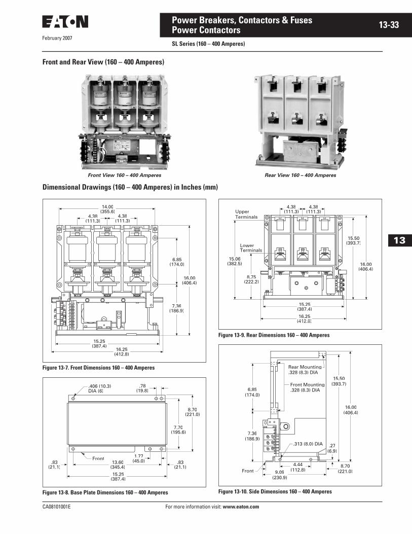
February 2007
CA08101001E For more information visit: www.eaton.com
13-33Power Breakers, Contactors & Fuses
13
Power ContactorsSL Series (160 – 400 Amperes)
Front and Rear View (160 – 400 Amperes)
Front View 160 – 400 Amperes Rear View 160 – 400 Amperes
Dimensional Drawings (160 – 400 Amperes) in Inches (mm)
Figure 13-7. Front Dimensions 160 – 400 Amperes
Figure 13-8. Base Plate Dimensions 160 – 400 Amperes
Figure 13-9. Rear Dimensions 160 – 400 Amperes
Figure 13-10. Side Dimensions 160 – 400 Amperes
14.00(355.6)
4.38(111.3)
6.85(174.0)174.0
4.38(111.3)
7.36(186.9)186.9
016.00(406.4)406.4
16.25(412.8)
15.25(387.4)
406 (10 3).406 (10.3)DIA (6)DIA (6)
Front
.78(19.8)
7.70(195.6)195.6
8.70(221.0)221.0
83.83(21.1)(21 1)
1.77(45.0)13.60
(345.4)
15.25(387.4)
.8383(21.1))
LowersTerminals
Upper4.38
(111.3)4.38
(111.3)
16.00(406.4)(406.4)
16 2516.25(412.8)(412 8)
15 2515.25(387.4)(387 4)
Teerminals
15.50)(393.7
8.75)(222.2)
15.06((382.5)
Front
.313 (8.0) DIA
Rear Mounting.328 (8.3) DIA
Front Mounting.328 (8.3) DIA
16.00(406.4)
15.50(393.7)
.27(6.9)
77.36(186.9)186.9
6.85(174.0)
9.09(230.9)
8.70(221.0)
4.44(112.8)
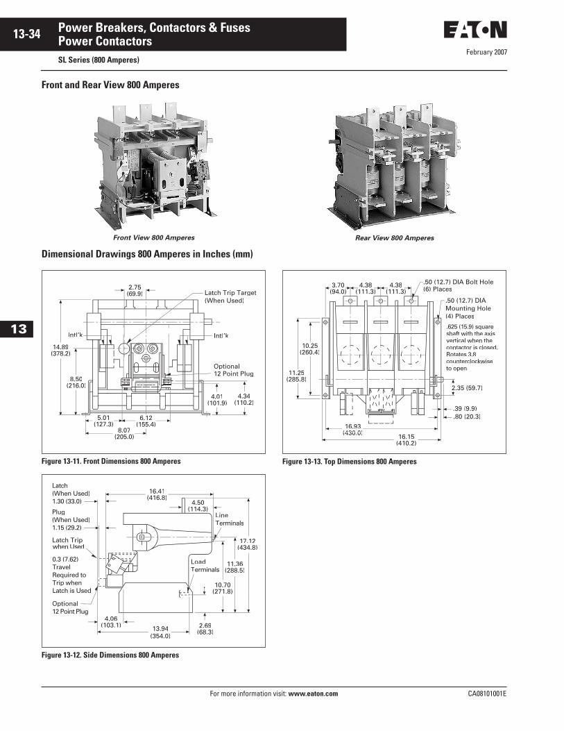
February 2007
13-34
For more information visit: www.eaton.com CA08101001E
Power Breakers, Contactors & Fuses
13
Power ContactorsSL Series (800 Amperes)
Front and Rear View 800 Amperes
Front View 800 Amperes
Dimensional Drawings 800 Amperes in Inches (mm)
Figure 13-11. Front Dimensions 800 Amperes
Figure 13-12. Side Dimensions 800 Amperes
Rear View 800 Amperes
Figure 13-13. Top Dimensions 800 Amperes
Latch Trip Target(When Used)
Optional12 Point Plug
4.34(110.2)
Intl’kI lIntl’’kk
4.01(101.9)
6.12(155.4)
8.07(205.0)
5.01(127.3)
8.50(216.0)216.0
14.89(378.2)
2.75(69.9)
Latch(When Used)1.30 (33.0)
Plug(When Used)1.15 (29.2)
Latch Tripwhen Used
0.3 (7.62)TravelRequired toTrip whenLatch is Used
Optional12 Point Plug
LLineTTerminals
13.94(354.0)
4.06(103.1) 2.69
(68.3)
10.70(271.8)
11.36(288.5)
17.12(434.8)
4.504.50
LoadTerminals
16.41(416.8)
5 (59.7)2.35
.50 (12.7) DIA Bolt Hole50 (12.7) DIA Bolt ((6) Places
.50 (12.7) DIA Mounting Hole(4) Places
.625 (15.9) square shaft with the axis vertical when the contactor is closed.Rotates 3.8counterclockwiseto open.
.39 (9.9).39 (
.80 (20.3).80
16.15(410.2)
16 9316.93(430.0)(430 0)
111.25(2285.8)
10.25(260.4)
3 703.70(94.0)(94 0)
4 384.38(111.3)111 3
4 384.38(111.3)111 3
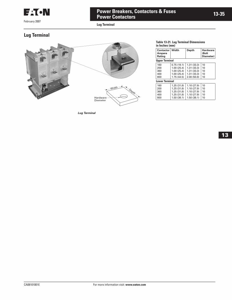
CA08101001E For more information visit: www.eaton.com
13-35Power Breakers, Contactors & Fuses
February 2007
13
Power ContactorsLug Terminal
Lug Terminal
Lug Terminal
WWididthth DepthDepth
HardwareDiameter
Table 13-21. Lug Terminal Dimensionsin Inches (mm)Contactor
Ampere
Rating
Width Depth Hardware
(Bolt
Diameter)
Upper Terminal160200360400800
0.75 (19.1)1.00 (25.4)1.00 (25.4)1.00 (25.4)1.75 (44.5)
1.31 (33.3)1.31 (33.3)1.31 (33.3)1.31 (33.3)2.00 (50.8)
1010101010
Lower Terminal160200360400800
1.25 (31.8)1.25 (31.8)1.25 (31.8)1.25 (31.8)1.50 (38.1)
1.10 (27.9)1.10 (27.9)1.10 (27.9)1.10 (27.9)1.50 (38.1)
1010101010

February 2007
13-36
For more information visit: www.eaton.com CA08101001E
Power Breakers, Contactors & Fuses
13
Power ContactorsProduct Selection
Product SelectionTable 13-22. Power Contactors Catalog Numbering System
SL N 01 2 S 5 A - 22 0
Mechanical Latch
160 – 400 Amperes
(Coil Voltage)
800 Amperes
(Coil Voltage)
0 = None1 = 24 Vdc 2 = 32 Vdc 3 = 48 Vdc 4 = 110/50,120/60,
or 125 Vdc5 = 220/50, 240/60
0 = None1 = 24 Vdc3 = 48 Vdc4 = 110 (50/60)5 = 220 (50/60) 6 = 96 – 125 Vdc
Type
01 = Open Contactor
Ampere Rating
1 = 1602 = 2003 = 3604 = 4008 = 800
Altitude
160 – 400 Amperes 800 Amperes
S = Standard -3281 to +6562 ft.(-1000 to +2000 m)
L = Low -11,483 to -3281 ft.(-3500 to -1000 m)
H = High +6562 to +13,123 ft.(+2000 to +4000 m)
S = Standard -3281 to +11,811 ft.(-1000 to +3600 m)
H = High +11,811 to +16,076 ft.(+3600 to +4900 m)
Auxiliary Contacts
160 – 400 Amperes 800 Amperes
22 = 2 NO, 2 NC28 = 2 NO, 8 NC37 = 3 NO, 7 NC46 = 4 NO, 6 NC55 = 5 NO, 5 NC64 = 6 NO, 4 NC73 = 7 NO, 3 NC82 = 8 NO, 2 NC
22 = 2 NO, 2 NC
Coil Voltage
A = 120/60B = 240/60S = 125 VdcU = 110/50W = 220/50
Coil Dropout Time
160 – 400 Amperes 800 Amperes
5 = 30 ms6 = 50 ms7 = 130 ms8 = 250 ms9 = 330 ms
6 = 50 ms7 = 130 ms8 = 250 ms9 = 330 ms
SL
Contactor
Series
Design
N = NEMAC = IEC
February 2007
CA08101001E For more information visit: www.eaton.com
13-37Power Breakers, Contactors & Fuses
13
Power ContactorsSL Series Factory Modified
SL Series Factory Modified
When Ordering Specify■ Refer to Catalog Number
Selection Guide. ■ Select Option Codes required.■ Select Base Unit Price.■ Add Pricing for Options Required.
Design and Test Standards■ UL 347, File No. E63257.■ CSA T.I.L. D-21, File No. LR28548.■ ANSI/NEMA ICS 3.■ IEC #60470.
Ordering InformationTable 13-23. Factory ModifiedDescription Option Code Price U.S. $
Base Price160 Ampere SL Contactor200 Ampere SL Contactor360 Ampere SL Contactor400 Ampere SL Contactor800 Ampere SL Contactor
12348
EnclosureOpen 01
Coil Voltage110/50, 120/60 ac220/50, 240/60 ac 125 Vdc
A, UB, WS
Coil Dropout Time 30 ms (160 – 400 Amperes Only) 50 ms130 ms250 ms330 ms
56789
Auxiliary Contacts2NO – 2NC2NO – 8NC (160 – 400 Amperes Only)3NO – 7NC (160 – 400 Amperes Only)4NO – 6NC (160 – 400 Amperes Only)5NO – 5NC (160 – 400 Amperes Only)6NO – 4NC (160 – 400 Amperes Only)7NO – 3NC (160 – 400 Amperes Only)8NO – 2NC (160 – 400 Amperes Only)
2228374655647382
Mechanical LatchNone24 Vdc Coil32 Vdc Coil (160 – 400 Amperes Only)48 Vdc Coil96 – 125 Vdc Coil (800 Ampere Only)110/50, 120/60 Coil125 Vdc Coil (160 – 400 Amperes Only)220/50, 240/60, Coil
01236445
Discount Symbol . . . . . . . . . . . . . . . . . . . . . . . . CB-2
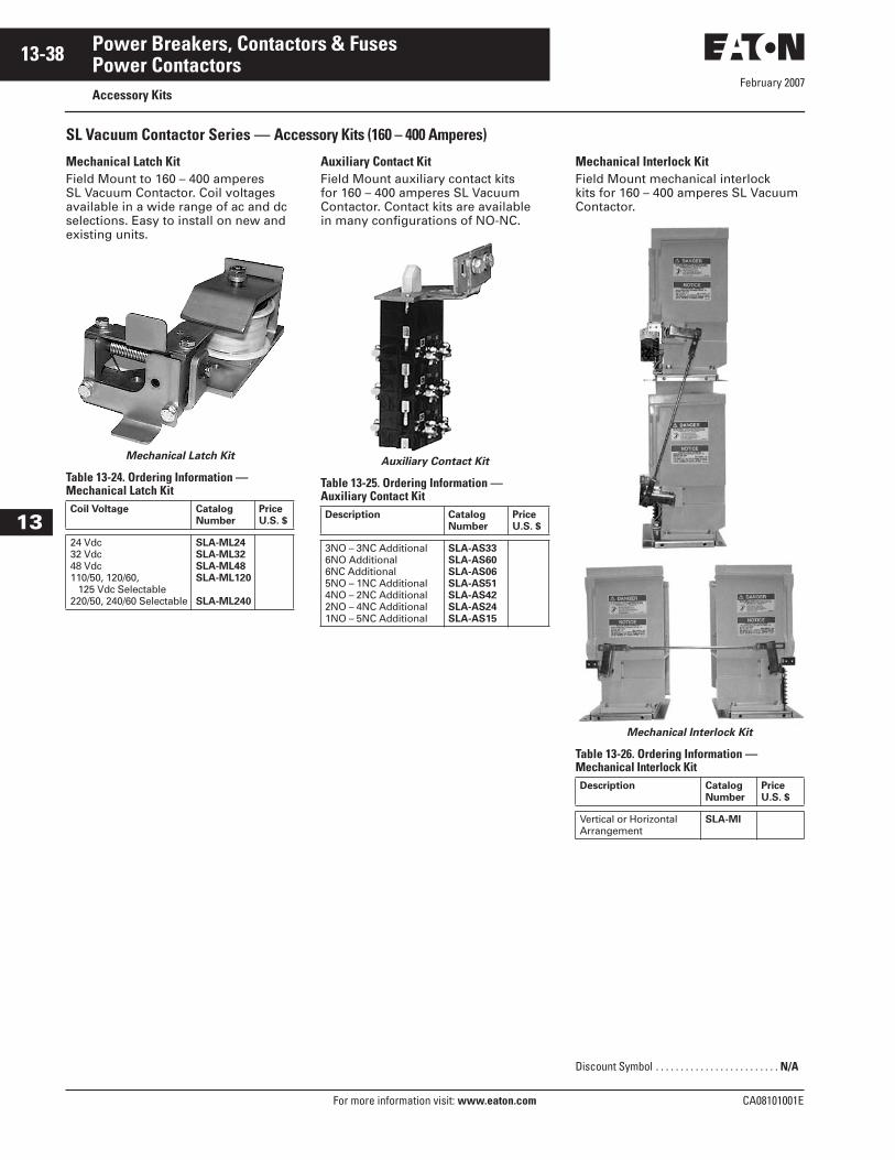
February 2007
13-38
For more information visit: www.eaton.com CA08101001E
Power Breakers, Contactors & Fuses
13
Power ContactorsAccessory Kits
SL Vacuum Contactor Series — Accessory Kits (160 – 400 Amperes)
Mechanical Latch KitField Mount to 160 – 400 amperes SL Vacuum Contactor. Coil voltages available in a wide range of ac and dc selections. Easy to install on new and existing units.
Mechanical Latch Kit
Table 13-24. Ordering Information — Mechanical Latch Kit
Auxiliary Contact KitField Mount auxiliary contact kits for 160 – 400 amperes SL Vacuum Contactor. Contact kits are available in many configurations of NO-NC.
Auxiliary Contact Kit
Table 13-25. Ordering Information — Auxiliary Contact Kit
Mechanical Interlock KitField Mount mechanical interlock kits for 160 – 400 amperes SL Vacuum Contactor.
Mechanical Interlock Kit
Table 13-26. Ordering Information — Mechanical Interlock Kit
Coil Voltage Catalog
Number
Price
U.S. $
24 Vdc32 Vdc48 Vdc110/50, 120/60, 125 Vdc Selectable220/50, 240/60 Selectable
SLA-ML24
SLA-ML32
SLA-ML48
SLA-ML120
SLA-ML240
Description Catalog
Number
Price
U.S. $
3NO – 3NC Additional6NO Additional6NC Additional5NO – 1NC Additional4NO – 2NC Additional2NO – 4NC Additional1NO – 5NC Additional
SLA-AS33
SLA-AS60
SLA-AS06
SLA-AS51
SLA-AS42
SLA-AS24
SLA-AS15
Description Catalog
Number
Price
U.S. $
Vertical or HorizontalArrangement
SLA-MI
Discount Symbol . . . . . . . . . . . . . . . . . . . . . . . . . N/A
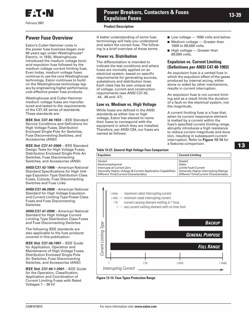
February 2007
CA08101001E For more information visit: www.eaton.com
13-39Power Breakers, Contactors & Fuses
13
Expulsion FusesProduct Description
Power Fuse OverviewEaton’s Cutler-Hammer roots in the power fuse business began over 60 years ago under Westinghouse� Electric. In 1935, Westinghouse introduced the medium voltage boric acid expulsion fuse followed by the medium voltage current limiting fuse. Even today, medium voltage fuses continue to use the core Westinghouse technology. Eaton continues to build on the Westinghouse technology leg-acy by engineering higher performance, cost-effective power fuse products.
Westinghouse and Cutler-Hammer medium voltage fuses are manufac-tured and tested to the requirements of the C37.4X series of standards. These standards are:
IEEE Std. C37.40-1933 – IEEE Standard Service Conditions and Definitions for High Voltage Fuses, Distribution Enclosed Single-Pole Air Switches, Fuse Disconnecting Switches, and Accessories (ANSI)
IEEE Std. C37.41-2000 – IEEE Standard Design Tests for High Voltage Fuses, Distribution Enclosed Single-Pole Air Switches, Fuse Disconnecting Switches, and Accessories (ANSI)
ANSI C37.42-1996 – American National Standard Specifications for High Volt-age Expulsion Type Distribution Class Fuses, Cutouts, Fuse Disconnecting Switches and Fuse Links
ANSI C37.46-2000 – American National Standard for High Voltage Expulsion and Current Limiting Type Power Class Fuses and Fuse Disconnecting Switches
ANSI C37.47-2000 – American National Standard for High Voltage Current Limiting Type Distribution Class Fuses and Fuse Disconnecting Switches
The following IEEE standards are also applicable to the fuse products covered in this publication:
IEEE Std. C37.48-1997 – IEEE Guide for Application, Operation and Maintenance of High Voltage Fuses, Distribution Enclosed Single-Pole Air Switches, Fuse Disconnecting Switches, and Accessories (ANSI)
IEEE Std. C37.48-1-2001 – IEEE Guide for the Operation, Classification, Application and Coordination of Current Limiting Fuses with Rated Voltages 1 – 38 kV
A better understanding of some fuse terminology will help you understand and select the correct fuse. The follow-ing is a brief overview of those terms.
Power vs. DistributionThe differentiation is intended to indicate the test conditions and where fuses are normally applied on an electrical system, based on specific requirements for generating sources, substations and distribution lines. Each class has its own unique set of voltage, current and construction requirements (see ANSI C37.42, .44, .46 and .47).
Low vs. Medium vs. High VoltageWhile fuses are defined in the ANSI standards as either low or high voltage, Eaton has elected to name their fuses to correspond with the equipment in which they are installed. Therefore, per ANSI C84, our fuses are named as follows:
■ Low voltage — 1000 volts and below.■ Medium voltage — Greater than
1000 to 69,000 volts.■ High voltage — Greater than
69,000 volts.
Expulsion vs. Current Limiting(Definitions per ANSI C47.40-1993)An expulsion fuse is a vented fuse in which the expulsion effect of the gases produced by internal arcing, either alone or aided by other mechanisms, results in current interruption.
An expulsion fuse is not current limit-ing and as a result limits the duration of a fault on the electrical system, not the magnitude.
A current limiting fuse is a fuse that, when its current responsive element is melted by a current within the fuse’s specified current limiting range, abruptly introduces a high resistance to reduce current magnitude and dura-tion, resulting in subsequent current interruption. Refer to Figure 13-14 for a features comparison.
Table 13-27. General High Voltage Fuse Comparison
Figure 13-14. Fuse Types Protection Range
Expulsion Current Limiting
VentedElectromechanicalInterrupts at Current ZeroGenerally Higher Voltage & Current Application CapabilitiesDifferent Time/Current Characteristics
SealedStaticLimits Fault CurrentGenerally Higher Interrupting RatingsDifferent Time/Current Characteristics
Cur
rent
Lim
itin
g Ty
pe
Interrupting Current
i i hr. i min. i max.
BACKUP
GENERAL PURPOSE
FULL RANGE
i max. —
i min. —
i hr. —
i —
maximum rated interrupting current
minimum rated interrupting current
current causing element melting in 1 hour
any current melting element with no time limit

February 2007
13-40
For more information visit: www.eaton.com CA08101001E
Power Breakers, Contactors & Fuses
13
Expulsion FusesProduct Description
Fuse TypesThere are three current limiting fuse types: Backup, General Purpose and Full Range. It is important that the user have an understanding of these defini-tions to ensure proper application of the fuse (Figure 13-14).
Backup Fuses: A fuse capable of inter-rupting all currents from the maximum rated interrupting current down to the rated minimum interrupting current.
Backup fuses are always used in a series with another interrupting device capable of interrupting currents below the fuse’s minimum interrupting current.
General Purpose Fuses: A fuse capable of interrupting all currents from the rated interrupting current down to the current that causes melting of the fus-ible element in no less than one hour.
General Purpose fuses are typically used to protect feeders and compo-nents such as transformers.
Full Range Fuses: A fuse capable of interrupting all currents from the rated interrupting current down to the minimum continuous current that causes melting of the fusible element, with the fuse applied at the maximum ambient temperature specified by the manufacturer.
General Fuse Component TermsReplaceable Fuse Unit: A replaceable fuse unit is a phrase used to describe a fuse that does not have a separate holder and refill assembly. In a replaceable fuse unit, the fuse is its own holder and is completely replaced after interruption.
Mounting: A mounting provides all the necessary parts to safely mount a fuse in its intended piece of equip-ment. The base is the metal support to which all other pieces attach. Insula-tors attach to the base and insulate the live fuse unit from the base and every-thing beyond the base. Live parts are the parts of the mounting that are energized once electricity is flowing. The live parts provide the means to hold the fuse unit in place, electrical contact, and a place to make line and load connections.
Non-Disconnect Mounting: A non-disconnect mounting does not provide a means for removing the fuse unit until the circuit is dead and the fuse unit can be removed manually. The fuse unit is held in place by friction through the use of fuse clips or by a cross bar.
Disconnect Mounting: The disconnect mounting allows the fuse unit to be removed (off load) using an insulated hook stick. The hookstick grabs a pull ring and disconnects the fuse unit, which may then be lifted out of its mounting.
Live Parts: Live parts were briefly discussed as part of the “Mounting” definition. Everything above the insula-tors on the mounting excluding the fuse unit, fuse holder, and the fuse end fit-tings (if required) are considered the live parts. Fuse end fittings are discussed next and are not required with non-dis-connect live parts, but are required and included with disconnect live parts. Live parts may be sold separately as replace-ment parts or for new OEM applications.
End Fittings: End fittings are metal parts that attach to each end of a fuse unit’s ferrules (end caps). As previ-ously mentioned, they are used solely with disconnect fuse applications or when converting a non-disconnect to a disconnect fuse configuration.
When end fittings are ordered, a fitting for each end of the fuse is included. Keep in mind that end fittings can become damaged in use and, therefore, are sold separately from the live parts when necessary. It is not necessary to purchase an entire set of live parts when only the end fittings are required.
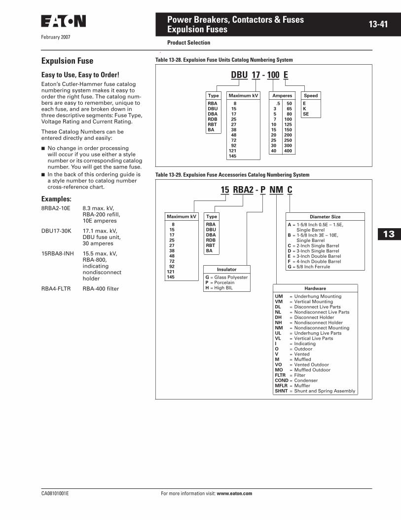
February 2007
CA08101001E For more information visit: www.eaton.com
13-41Power Breakers, Contactors & Fuses
13
Expulsion FusesProduct Selection
Expulsion Fuse
Easy to Use, Easy to Order!Eaton’s Cutler-Hammer fuse catalog numbering system makes it easy to order the right fuse. The catalog num-bers are easy to remember, unique to each fuse, and are broken down in three descriptive segments: Fuse Type, Voltage Rating and Current Rating.
These Catalog Numbers can be entered directly and easily:
■ No change in order processing will occur if you use either a style number or its corresponding catalog number. You will get the same fuse.
■ In the back of this ordering guide is a style number to catalog number cross-reference chart.
Examples:8RBA2-10E 8.3 max. kV,
RBA-200 refill,10E amperes
DBU17-30K 17.1 max. kV,DBU fuse unit,30 amperes
15RBA8-INH 15.5 max. kV,RBA-800,indicating nondisconnectholder
RBA4-FLTR RBA-400 filter
Table 13-28. Expulsion Fuse Units Catalog Numbering System
Table 13-29. Expulsion Fuse Accessories Catalog Numbering System
DBU 17 - 100 E
Type
RBA
DBU
DBA
RDB
RBT
BA
Amperes
.5
3
5
7
10
15
20
25
30
40
50
65
80
100
125
150
200
250
300
400
Maximum kV
8 15
17
25
27
38
48
72
92
121
145
Speed
E
K
SE
15 RBA2 - P NM C
Type
RBA
DBU
DBA
RDB
RBT
BA
Maximum kV
8
15
17
25
27
38
48
72
92
121
145
Insulator
G = Glass PolyesterP = PorcelainH = High BIL Hardware
UM = Underhung MountingVM = Vertical MountingDL = Disconnect Live PartsNL = Nondisconnect Live PartsDH = Disconnect HolderNH = Nondisconnect HolderNM = Nondisconnect MountingUL = Underhung Live PartsVL = Vertical Live PartsI = IndicatingO = OutdoorV = VentedM = MuffledVO = Vented OutdoorMO = Muffled OutdoorFLTR = FilterCOND = CondenserMFLR = MufflerSHNT = Shunt and Spring Assembly
Diameter Size
A = 1-5/8 Inch 0.5E – 1.5E, Single Barrel
B = 1-5/8 Inch 3E – 10E, Single Barrel
C = 2-Inch Single BarrelD = 3-Inch Single BarrelE = 3-Inch Double BarrelF = 4-Inch Double BarrelG = 5/8 Inch Ferrule
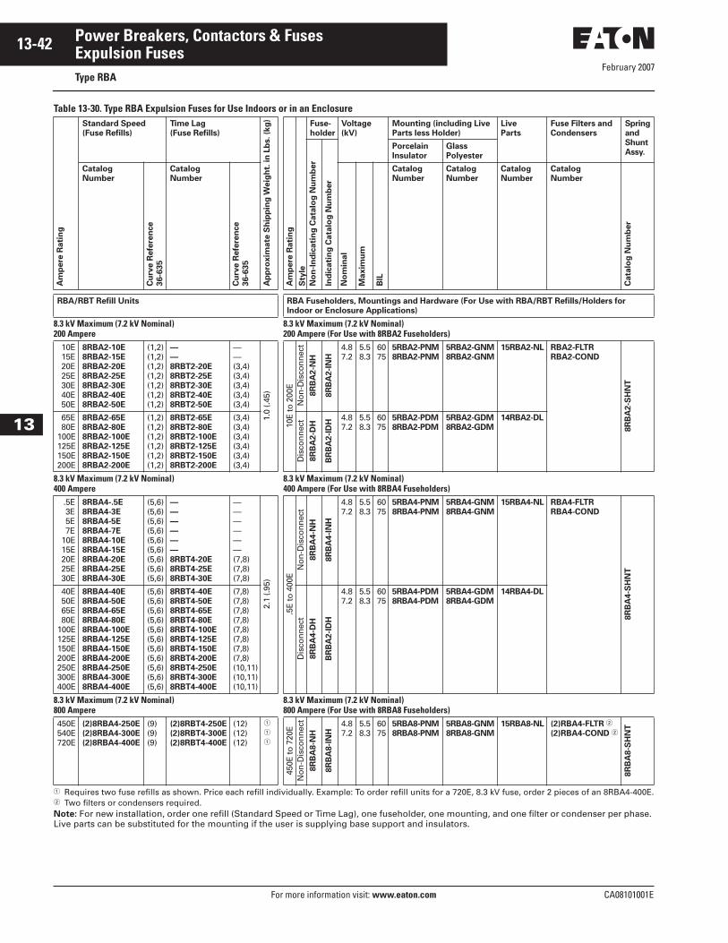
February 2007
13-42
For more information visit: www.eaton.com CA08101001E
Power Breakers, Contactors & Fuses
13
Expulsion FusesType RBA
Table 13-30. Type RBA Expulsion Fuses for Use Indoors or in an Enclosure
� Requires two fuse refills as shown. Price each refill individually. Example: To order refill units for a 720E, 8.3 kV fuse, order 2 pieces of an 8RBA4-400E.� Two filters or condensers required.Note: For new installation, order one refill (Standard Speed or Time Lag), one fuseholder, one mounting, and one filter or condenser per phase. Live parts can be substituted for the mounting if the user is supplying base support and insulators.
Am
pere
Rati
ng
Standard Speed
(Fuse Refills)
Time Lag
(Fuse Refills)
Ap
pro
xim
ate
Sh
ipp
ing
Weig
ht.
in
Lb
s. (k
g)
Am
pere
Rati
ng
Sty
le
Fuse-
holder
Voltage
(kV)
Mounting (including Live
Parts less Holder)
Live
Parts
Fuse Filters and
Condensers
Spring
and
Shunt
Assy.
No
n-I
nd
icati
ng
Cata
log
Nu
mb
er
Ind
icati
ng
Cata
log
Nu
mb
er
Porcelain
Insulator
Glass
Polyester
Catalog
Number
Cu
rve R
efe
ren
ce
36-6
35
Catalog
Number
Cu
rve R
efe
ren
ce
36-6
35
No
min
al
Maxim
um
BIL
Catalog
Number
Catalog
Number
Catalog
Number
Catalog
Number
Cata
log
Nu
mb
er
RBA/RBT Refill Units RBA Fuseholders, Mountings and Hardware (For Use with RBA/RBT Refills/Holders for
Indoor or Enclosure Applications)
8.3 kV Maximum (7.2 kV Nominal)200 Ampere
8.3 kV Maximum (7.2 kV Nominal)200 Ampere (For Use with 8RBA2 Fuseholders)
10E 15E 20E 25E 30E 40E 50E
8RBA2-10E
8RBA2-15E
8RBA2-20E
8RBA2-25E
8RBA2-30E
8RBA2-40E
8RBA2-50E
(1,2)(1,2)(1,2)(1,2)(1,2)(1,2)(1,2)
—
—
8RBT2-20E
8RBT2-25E
8RBT2-30E
8RBT2-40E
8RBT2-50E
——(3,4)(3,4)(3,4)(3,4)(3,4)
1.0
(.45)
10E
to 2
00E
No
n-D
isco
nn
ect
8R
BA
2-N
H
8R
BA
2-I
NH
4.87.2
5.58.3
6075
5RBA2-PNM
8RBA2-PNM
5RBA2-GNM
8RBA2-GNM
15RBA2-NL RBA2-FLTR
RBA2-COND
8R
BA
2-S
HN
T
65E 80E100E125E150E200E
8RBA2-65E
8RBA2-80E
8RBA2-100E
8RBA2-125E
8RBA2-150E
8RBA2-200E
(1,2)(1,2)(1,2)(1,2)(1,2)(1,2)
8RBT2-65E
8RBT2-80E
8RBT2-100E
8RBT2-125E
8RBT2-150E
8RBT2-200E
(3,4)(3,4)(3,4)(3,4)(3,4)(3,4)
Dis
con
nec
t8R
BA
2-D
H
BR
BA
2-I
DH
4.87.2
5.58.3
6075
5RBA2-PDM
8RBA2-PDM
5RBA2-GDM
8RBA2-GDM
14RBA2-DL
8.3 kV Maximum (7.2 kV Nominal)400 Ampere
8.3 kV Maximum (7.2 kV Nominal)400 Ampere (For Use with 8RBA4 Fuseholders)
.5E 3E 5E 7E 10E 15E 20E 25E 30E
8RBA4-.5E
8RBA4-3E
8RBA4-5E
8RBA4-7E
8RBA4-10E
8RBA4-15E
8RBA4-20E
8RBA4-25E
8RBA4-30E
(5,6)(5,6)(5,6)(5,6)(5,6)(5,6)(5,6)(5,6)(5,6)
—
—
—
—
—
—
8RBT4-20E
8RBT4-25E
8RBT4-30E
——————(7,8)(7,8)(7,8)
2.1
(.95)
.5E
to 4
00E
No
n-D
isco
nn
ect
8R
BA
4-N
H
8R
BA
4-I
NH
4.87.2
5.58.3
6075
5RBA4-PNM
8RBA4-PNM
5RBA4-GNM
8RBA4-GNM
15RBA4-NL RBA4-FLTR
RBA4-COND
8R
BA
4-S
HN
T
40E 50E 65E 80E100E125E150E200E250E300E400E
8RBA4-40E
8RBA4-50E
8RBA4-65E
8RBA4-80E
8RBA4-100E
8RBA4-125E
8RBA4-150E
8RBA4-200E
8RBA4-250E
8RBA4-300E
8RBA4-400E
(5,6)(5,6)(5,6)(5,6)(5,6)(5,6)(5,6)(5,6)(5,6)(5,6)(5,6)
8RBT4-40E
8RBT4-50E
8RBT4-65E
8RBT4-80E
8RBT4-100E
8RBT4-125E
8RBT4-150E
8RBT4-200E
8RBT4-250E
8RBT4-300E
8RBT4-400E
(7,8)(7,8)(7,8)(7,8)(7,8)(7,8)(7,8)(7,8)(10,11)(10,11)(10,11)
Dis
con
nec
t8R
BA
4-D
H
BR
BA
2-I
DH
4.87.2
5.58.3
6075
5RBA4-PDM
8RBA4-PDM
5RBA4-GDM
8RBA4-GDM
14RBA4-DL
8.3 kV Maximum (7.2 kV Nominal)800 Ampere
8.3 kV Maximum (7.2 kV Nominal)800 Ampere (For Use with 8RBA8 Fuseholders)
450E540E720E
(2)8RBA4-250E
(2)8RBA4-300E
(2)8RBA4-400E
(9)(9)(9)
(2)8RBT4-250E
(2)8RBT4-300E
(2)8RBT4-400E
(12)(12)(12)
�
�
�
450E
to 7
20E
No
n-D
isco
nn
ect
8R
BA
8-N
H
8R
BA
8-I
NH
4.87.2
5.58.3
6075
5RBA8-PNM
8RBA8-PNM
5RBA8-GNM
8RBA8-GNM
15RBA8-NL (2)RBA4-FLTR �
(2)RBA4-COND �
8R
BA
8-S
HN
T

February 2007
CA08101001E For more information visit: www.eaton.com
13-43Power Breakers, Contactors & Fuses
13
Expulsion FusesType RBA
Table 13-31. Type RBA Expulsion Fuses for Use Outdoors
� Requires two fuse refills as shown. Price each refill individually. Example: To order refill units for a 720E, 15 kV fuse, order 2 pieces of an 8RBA4-400E.� Two filters or condensers required.Note: For new installation, order one refill (Standard Speed or Time Lag), one fuseholder, one mounting, and one filter or condenser per phase. Live parts can be substituted for the mounting if the user is supplying base support and insulators.
Am
pere
Rati
ng
Standard Speed
(Fuse Refills)
Time Lag
(Fuse Refills)
Ap
pro
xim
ate
Sh
ipp
ing
Weig
ht.
in
Lb
s. (k
g)
Am
pere
Rati
ng
Sty
le
Fuse-
holder
Voltage (kV) Mounting (including Live
Parts less Holder)
Live
Parts
Fuse Filters and
Condensers
Spring
and
Shunt
Assy.
No
n-I
nd
icati
ng
Cata
log
Nu
mb
er
Ind
icati
ng
Cata
log
Nu
mb
er
Porcelain
Insulator
Glass
Polyester
Catalog
NumberC
urv
e R
efe
ren
ce
36-6
35
Catalog
Number
Cu
rve R
efe
ren
ce
36-6
35
No
min
al
Maxim
um
BIL
Catalog
Number
Catalog
Number
Cata
log
Nu
mb
er
Catalog
Number
Cata
log
Nu
mb
er
RBA/RBT Refill Units RBA Fuseholders, Mountings and Hardware (For Use with RBA/RBT Refills/Holders
for Indoor or Enclosure Applications)
15.5 kV Maximum (14.4 kV Nominal)200 Ampere
15.5 kV Maximum (14.4 kV Nominal)200 Ampere (For Use with 15RBA2 Fuseholders)
10E 15E 20E 25E 30E 40E 50E
15RBA2-10E
15RBA2-15E
15RBA2-20E
15RBA2-25E
15RBA2-30E
15RBA2-40E
15RBA2-50E
(1,2)(1,2)(1,2)(1,2)(1,2)(1,2)(1,2)
—
—
15RBT2-20E
15RBT2-25E
15RBT2-30E
15RBT2-40E
15RBT2-50E
——(3,4)(3,4)(3,4)(3,4)(3,4)
1.1
(.5)
10E
to 2
00E
No
n-D
isco
nn
ect
15R
BA
2-N
H
15R
BA
2-I
NH
13.813.8
15.515.5
95110
14RBA2-PNM
15RBA2-PNM
14R
BA
2-G
NM
15R
BA
2-N
L
RBA2-FLTR
RBA2-COND
15R
BA
2-S
HN
T
65E 80E100E125E150E200E
15RBA2-65E
15RBA2-80E
15RBA2-100E
15RBA2-125E
15RBA2-150E
15RBA2-200E
(1,2)(1,2)(1,2)(1,2)(1,2)(1,2)
15RBT2-65E
15RBT2-80E
15RBT2-100E
15RBT2-125E
15RBT2-150E
15RBT2-200E
(3,4)(3,4)(3,4)(3,4)(3,4)(3,4)
Dis
con
nec
t
15R
BA
2-D
H
15R
BA
2-I
DH 13.8
13.815.515.5
95110
14RBA2-PDM
15RBA2-PDM
14R
BA
2-G
DM
38R
BA
2-D
L
15.5 kV Maximum (14.4 kV Nominal)400 Ampere
15.5 kV Maximum (14.4 kV Nominal)400 Ampere (For Use with 15RBA4 Fuseholders)
.5E 3E 5E 7E 10E 15E 20E 25E 30E
15RBA4-.5E
15RBA4-3E
15RBA4-5E
15RBA4-7E
15RBA4-10E
15RBA4-15E
15RBA4-20E
15RBA4-25E
15RBA4-30E
(5,6)(5,6)(5,6)(5,6)(5,6)(5,6)(5,6)(5,6)(5,6)
—
—
—
—
—
—
15RBT4-20E
15RBT4-25E
15RBT4-30E
——————(7,8)(7,8)(7,8)
2.3
(1.0
)
.5E
to 4
00E
No
n-D
isco
nn
ect
15R
BA
4-N
H
15R
BA
4-I
NH
13.813.8
15.515.5
95110
14RBA4-PNM
15RBA4-PNM14R
BA
4-G
NM
15R
BA
4-N
L
RBA4-FLTR
RBA4-COND
15R
BA
4-S
HN
T
40E 50E 65E 80E100E125E150E200E250E300E400E
15RBA4-40E
15RBA4-50E
15RBA4-65E
15RBA4-80E
15RBA4-100E
15RBA4-125E
15RBA4-150E
15RBA4-200E
15RBA4-250E
15RBA4-300E
15RBA4-400E
(5,6)(5,6)(5,6)(5,6)(5,6)(5,6)(5,6)(5,6)(5,6)(5,6)(5,6)
15RBT4-40E
15RBT4-50E
15RBT4-65E
15RBT4-80E
15RBT4-100E
15RBT4-125E
15RBT4-150E
15RBT4-200E
15RBT4-250E
15RBT4-300E
15RBT4-400E
(7,8)(7,8)(7,8)(7,8)(7,8)(7,8)(7,8)(7,8)(10,11)(10,11)(10,11)
Dis
con
nec
t
15R
BA
4-D
H
15R
BA
4-I
DH
14RBA4-PDM
15RBA4-PDM
14R
BA
4-G
DM
15R
BA
4-D
L
13.813.8
15.515.5
95110
15.5 kV Maximum (14.4 kV Nominal)800 Ampere
15.5 kV Maximum (14.4 kV Nominal)800 Ampere (For Use with 15RBA8 Fuseholders)
450E540E720E
(2)15RBA4-250E
(2)15RBA4-300E
(2)15RBA4-400E
(9)(9)(9)
(2)15RBT4-250E
(2)15RBT4-300E
(2)15RBT4-400E
(12)(12)(12)
�
�
�
450E
to 7
20E
No
n-D
isco
nn
ect
15R
BA
8-N
H
15R
BA
8-I
NH
13.813.8
15.515.5
95110
14RBA8-PNM
15RBA8-PNM
14R
BA
8-G
NM
15R
BA
8-N
L
(2)RBA4-FLTR �
(2)RBA4-COND �
15R
BA
8-S
HN
T

February 2007
13-44
For more information visit: www.eaton.com CA08101001E
Power Breakers, Contactors & Fuses
13
Expulsion FusesType RBA
Table 13-32. Type RBA Expulsion Fuses for Use Indoors or in an Enclosure
� Requires two fuse refills as shown. Price each refill individually. Example: To order refill units for a 720E, 25 kV fuse, order 2 pieces of an 8RBA4-400E.� Two filters or condensers required.Note: For new installation, order one refill (Standard Speed or Time Lag), one fuseholder, one mounting, and one filter or condenser per phase. Live parts can be substituted for the mounting if the user is supplying base support and insulators.
Am
pere
Rati
ng
Standard Speed
(Fuse Refills)
Time Lag
(Fuse Refills)
Ap
pro
xim
ate
Sh
ipp
ing
Weig
ht.
in
Lb
s (
kg
)
Am
pere
Rati
ng
Sty
le
Fuse-
holder
Voltage (kV) Mounting (including Live
Parts less Holder)
Live
Parts
Fuse Filters and
Condensers
Spring
and
Shunt
Assy.
No
n-I
nd
icati
ng
Cata
log
Nu
mb
er
Ind
icati
ng
Cata
log
Nu
mb
er
Porcelain
Insulator
Glass
Polyester
Catalog
Number
Cu
rve R
efe
ren
ce
36-6
35
Catalog
Number
Cu
rve R
efe
ren
ce
36-6
35
No
min
al
Maxim
um
BIL
Catalog
Number
Catalog
Number
Cata
log
Nu
mb
er
Catalog
Number
Cata
log
Nu
mb
er
RBA/RBT Refill Units RBA Fuseholders, Mountings and Hardware (For Use with RBA/RBT Refills/Holders
for Indoor or Enclosure Applications)
25.5 kV Maximum (23.0 kV Nominal)200 Ampere
25.5 kV Maximum (23.0 kV Nominal)200 Ampere (For Use with 25RBA2 Fuseholders)
10E 15E 20E 25E 30E 40E 50E
25RBA2-10E
25RBA2-15E
25RBA2-20E
25RBA2-25E
25RBA2-30E
25RBA2-40E
25RBA2-50E
(1,2)(1,2)(1,2)(1,2)(1,2)(1,2)(1,2)
——25RBT2-20E
25RBT2-25E
25RBT2-30E
25RBT2-40E
25RBT2-50E
——(3,4)(3,4)(3,4)(3,4)(3,4)
1.3
(.6)
10E
to 2
00E
No
n-D
isco
nn
ect
25R
BA
2-N
H
25R
BA
2-I
NH
23.0 25.5 150 25RBA2-PNM —
38R
BA
2-N
L
RBA2-FLTR
RBA2-COND
25R
BA
2-S
HN
T
65E 80E100E125E150E200E
25RBA2-65E
25RBA2-80E
25RBA2-100E
25RBA2-125E
25RBA2-150E
25RBA2-200E
(1,2)(1,2)(1,2)(1,2)(1,2)(1,2)
25RBT2-65E
25RBT2-80E
25RBT2-100E
25RBT2-125E
25RBT2-150E
25RBT2-200E
(3,4)(3,4)(3,4)(3,4)(3,4)(3,4)
Dis
con
nec
t
25R
BA
2-D
H
25R
BA
2-I
DH 23.0 25.5 150 25RBA2-PDM —
38R
BA
2-D
L
25.5 kV Maximum (23.0 kV Nominal)400 Ampere
25.5 kV Maximum (23.0 kV Nominal)400 Ampere (For Use with 25RBA4 Fuseholders)
.5E 3E 5E 7E 10E 15E 20E 25E 30E
25RBA4-.5E
25RBA4-3E
25RBA4-5E
25RBA4-7E
25RBA4-10E
25RBA4-15E
25RBA4-20E
25RBA4-25E
25RBA4-30E
(5,6)(5,6)(5,6)(5,6)(5,6)(5,6)(5,6)(5,6)(5,6)
——————25RBT4-20E
25RBT4-25E
25RBT4-30E
——————(7,8)(7,8)(7,8)
2.7
(1.2
)
.5E
to 3
00E
No
n-D
isco
nn
ect
25R
BA
4-N
H
25R
BA
4-I
NH
23.0 25.5 150 25RBA4-PNM —
38R
BA
4-N
L
RBA4-FLTR
RBA4-COND
25R
BA
4-S
HN
T
40E 50E 65E 80E100E125E150E200E250E300E
25RBA4-40E
25RBA4-50E
25RBA4-65E
25RBA4-80E
25RBA4-100E
25RBA4-125E
25RBA4-150E
25RBA4-200E
25RBA4-250E
25RBA4-300E
(5,6)(5,6)(5,6)(5,6)(5,6)(5,6)(5,6)(5,6)(5,6)(5,6)
25RBT4-40E
25RBT4-50E
25RBT4-65E
25RBT4-80E
25RBT4-100E
25RBT4-125E
25RBT4-150E
25RBT4-200E
25RBT4-250E
25RBT4-300E
(7,8)(7,8)(7,8)(7,8)(7,8)(7,8)(7,8)(7,8)(10,11)(10,11)
Dis
con
nec
t
25R
BA
4-D
H
25R
BA
4-I
DH
23.0 25.5 150 25RBA4-PDM —
38R
BA
4-D
L
25.5 kV Maximum (23.0 kV Nominal)800 Ampere
25.5 kV Maximum (23.0 kV Nominal)800 Ampere (For Use with 25RBA8 Fuseholders)
450E540E
(2)25RBA4-250E
(2)25RBA4-300E
(9)(9)
(2)25RBT4-250E
(2)25RBT4-300E
(12)(12)
�
�
450E
to 5
40E
No
n-D
isco
nn
ect
25R
BA
8-N
H
25R
BA
8-I
NH
23.0 25.5 150 25RBA8-PNM —
38R
BA
8-N
L
(2)RBA4-FLTR �
(2)RBA4-COND �
25R
BA
8-S
HN
T
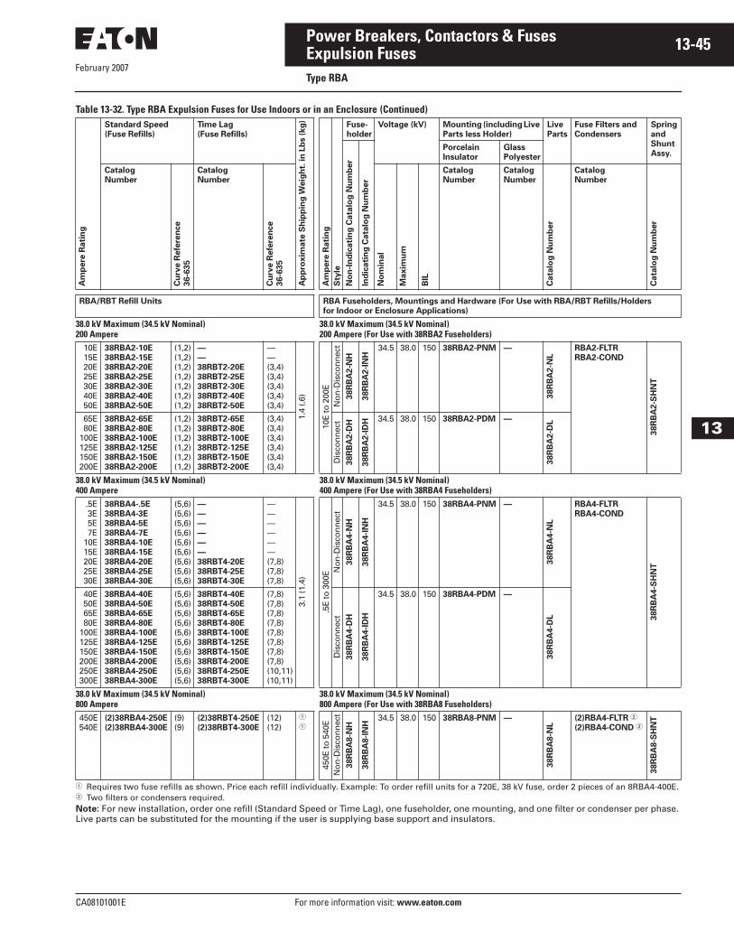
February 2007
CA08101001E For more information visit: www.eaton.com
13-45Power Breakers, Contactors & Fuses
13
Expulsion FusesType RBA
Table 13-32. Type RBA Expulsion Fuses for Use Indoors or in an Enclosure (Continued)
� Requires two fuse refills as shown. Price each refill individually. Example: To order refill units for a 720E, 38 kV fuse, order 2 pieces of an 8RBA4-400E.� Two filters or condensers required.Note: For new installation, order one refill (Standard Speed or Time Lag), one fuseholder, one mounting, and one filter or condenser per phase. Live parts can be substituted for the mounting if the user is supplying base support and insulators.
Am
pere
Rati
ng
Standard Speed
(Fuse Refills)
Time Lag
(Fuse Refills)
Ap
pro
xim
ate
Sh
ipp
ing
Weig
ht.
in
Lb
s (
kg
)
Am
pere
Rati
ng
Sty
le
Fuse-
holder
Voltage (kV) Mounting (including Live
Parts less Holder)
Live
Parts
Fuse Filters and
Condensers
Spring
and
Shunt
Assy.
No
n-I
nd
icati
ng
Cata
log
Nu
mb
er
Ind
icati
ng
Cata
log
Nu
mb
er
Porcelain
Insulator
Glass
Polyester
Catalog
NumberC
urv
e R
efe
ren
ce
36-6
35
Catalog
Number
Cu
rve R
efe
ren
ce
36-6
35
No
min
al
Maxim
um
BIL
Catalog
Number
Catalog
Number
Cata
log
Nu
mb
er
Catalog
Number
Cata
log
Nu
mb
er
RBA/RBT Refill Units RBA Fuseholders, Mountings and Hardware (For Use with RBA/RBT Refills/Holders
for Indoor or Enclosure Applications)
38.0 kV Maximum (34.5 kV Nominal)200 Ampere
38.0 kV Maximum (34.5 kV Nominal)200 Ampere (For Use with 38RBA2 Fuseholders)
10E 15E 20E 25E 30E 40E 50E
38RBA2-10E
38RBA2-15E
38RBA2-20E
38RBA2-25E
38RBA2-30E
38RBA2-40E
38RBA2-50E
(1,2)(1,2)(1,2)(1,2)(1,2)(1,2)(1,2)
—
—
38RBT2-20E
38RBT2-25E
38RBT2-30E
38RBT2-40E
38RBT2-50E
——(3,4)(3,4)(3,4)(3,4)(3,4)
1.4
(.6)
10E
to 2
00E
No
n-D
isco
nn
ect
38R
BA
2-N
H
38R
BA
2-I
NH
34.5 38.0 150 38RBA2-PNM —
38R
BA
2-N
L
RBA2-FLTR
RBA2-COND
38R
BA
2-S
HN
T
65E 80E100E125E150E200E
38RBA2-65E
38RBA2-80E
38RBA2-100E
38RBA2-125E
38RBA2-150E
38RBA2-200E
(1,2)(1,2)(1,2)(1,2)(1,2)(1,2)
38RBT2-65E
38RBT2-80E
38RBT2-100E
38RBT2-125E
38RBT2-150E
38RBT2-200E
(3,4)(3,4)(3,4)(3,4)(3,4)(3,4)
Dis
con
nec
t38R
BA
2-D
H
38R
BA
2-I
DH 34.5 38.0 150 38RBA2-PDM —
38R
BA
2-D
L
38.0 kV Maximum (34.5 kV Nominal)400 Ampere
38.0 kV Maximum (34.5 kV Nominal)400 Ampere (For Use with 38RBA4 Fuseholders)
.5E 3E 5E 7E 10E 15E 20E 25E 30E
38RBA4-.5E
38RBA4-3E
38RBA4-5E
38RBA4-7E
38RBA4-10E
38RBA4-15E
38RBA4-20E
38RBA4-25E
38RBA4-30E
(5,6)(5,6)(5,6)(5,6)(5,6)(5,6)(5,6)(5,6)(5,6)
—
—
—
—
—
—
38RBT4-20E
38RBT4-25E
38RBT4-30E
——————(7,8)(7,8)(7,8)
3.1
(1.4
)
.5E
to 3
00E N
on
-Dis
con
nec
t38R
BA
4-N
H
38R
BA
4-I
NH
34.5 38.0 150 38RBA4-PNM —
38R
BA
4-N
L
RBA4-FLTR
RBA4-COND
38R
BA
4-S
HN
T
40E 50E 65E 80E100E125E150E200E250E300E
38RBA4-40E
38RBA4-50E
38RBA4-65E
38RBA4-80E
38RBA4-100E
38RBA4-125E
38RBA4-150E
38RBA4-200E
38RBA4-250E
38RBA4-300E
(5,6)(5,6)(5,6)(5,6)(5,6)(5,6)(5,6)(5,6)(5,6)(5,6)
38RBT4-40E
38RBT4-50E
38RBT4-65E
38RBT4-80E
38RBT4-100E
38RBT4-125E
38RBT4-150E
38RBT4-200E
38RBT4-250E
38RBT4-300E
(7,8)(7,8)(7,8)(7,8)(7,8)(7,8)(7,8)(7,8)(10,11)(10,11)
Dis
con
nec
t38R
BA
4-D
H
38R
BA
4-I
DH
38RBA4-PDM —
38R
BA
4-D
L
34.5 38.0 150
38.0 kV Maximum (34.5 kV Nominal)800 Ampere
38.0 kV Maximum (34.5 kV Nominal)800 Ampere (For Use with 38RBA8 Fuseholders)
450E540E
(2)38RBA4-250E
(2)38RBA4-300E
(9)(9)
(2)38RBT4-250E
(2)38RBT4-300E
(12)(12)
�
�
450E
to 5
40E
No
n-D
isco
nn
ect
38R
BA
8-N
H
38R
BA
8-I
NH
34.5 38.0 150 38RBA8-PNM —
38R
BA
8-N
L
(2)RBA4-FLTR �
(2)RBA4-COND �
38R
BA
8-S
HN
T
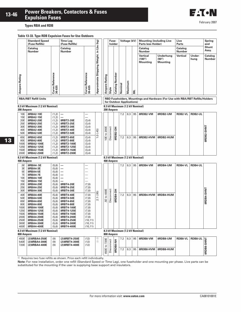
February 2007
13-46
For more information visit: www.eaton.com CA08101001E
Power Breakers, Contactors & Fuses
13
Expulsion FusesTypes RBA and RDB
Table 13-33. Type RDB Expulsion Fuses for Use Outdoors
� Requires two fuse refills as shown. Price each refill individually. Note: For new installation, order one refill (Standard Speed or Time Lag), one fuseholder and one mounting per phase. Live parts can be substituted for the mounting if the user is supplying base support and insulators.
Am
pere
Rati
ng
Standard Speed
(Fuse Refills)
Time Lag
(Fuse Refills)
Ap
pro
xim
ate
Sh
ipp
ing
Weig
ht.
in
Lb
s (
kg
)
Am
pere
Rati
ng
Fuse-
holder
Voltage (kV) Mounting (including Live
Parts less Holder)
Live
Parts
Spring
and
Shunt
Assy.Catalog
NumberC
urv
e R
efe
ren
ce
36-6
35
Catalog
Number
Cu
rve R
efe
ren
ce
36-6
35
Sty
le
Cata
log
Nu
mb
er
No
min
al
Maxim
um
BIL
Catalog
Number
Catalog
Number
Vertical
(180°)
Mounting
Underhung
(90°)
Mounting
Vertical Under-
hung
Catalog
Number
RBA/RBT Refill Units RBD Fuseholders, Mountings and Hardware (For Use with RBA/RBT Refills/Holders
for Outdoor Applications)
8.3 kV Maximum (7.2 kV Nominal)200 Ampere
8.3 kV Maximum (7.2 kV Nominal)200 Ampere
10E 15E 20E 25E 30E 40E 50E
8RBA2-10E
8RBA2-15E
8RBA2-20E
8RBA2-25E
8RBA2-30E
8RBA2-40E
8RBA2-50E
(1,2)(1,2)(1,2)(1,2)(1,2)(1,2)(1,2)
—
—
8RBT2-20E
8RBT2-25E
8RBT2-30E
8RBT2-40E
8RBT2-50E
——(3,4)(3,4)(3,4)(3,4)(3,4)
1.0
(.45)
10E
to 2
00E
Dis
con
nec
t
8R
DB
2-D
H7.2 8.3 95 8RDB2-VM 8RDB2-UM RDB2-VL RDB2-UL
8R
DB
2-S
HN
T
65E 80E100E125E150E200E
8RBA2-65E
8RBA2-80E
8RBA2-100E
8RBA2-125E
8RBA2-150E
8RBA2-200E
(1,2)(1,2)(1,2)(1,2)(1,2)(1,2)
8RBT2-65E
8RBT2-80E
8RBT2-100E
8RBT2-125E
8RBT2-150E
8RBT2-200E
(3,4)(3,4)(3,4)(3,4)(3,4)(3,4)
7.2 8.3 95 8RDB2-HVM 8RDB2-HUM
8.3 kV Maximum (7.2 kV Nominal)400 Ampere
8.3 kV Maximum (7.2 kV Nominal)400 Ampere
.5E 3E 5E 7E 10E 15E 20E 25E 30E
8RBA4-.5E
8RBA4-3E
8RBA4-5E
8RBA4-7E
8RBA4-10E
8RBA4-15E
8RBA4-20E
8RBA4-25E
8RBA4-30E
(5,6)(5,6)(5,6)(5,6)(5,6)(5,6)(5,6)(5,6)(5,6)
—
—
—
—
—
—
8RBT4-20E
8RBT4-25E
8RBT4-30E
——————(7,8)(7,8)(7,8)
2.1
(.95)
.5E
to 4
00E
Dis
con
nec
t
8R
DB
4-D
H
7.2 8.3 95 8RDB4-VM 8RDB4-UM RDB4-VL RDB4-UL
8R
DB
4-S
HN
T
40E 50E 65E 80E100E125E150E200E250E300E400E
8RBA4-40E
8RBA4-50E
8RBA4-65E
8RBA4-80E
8RBA4-100E
8RBA4-125E
8RBA4-150E
8RBA4-200E
8RBA4-250E
8RBA4-300E
8RBA4-400E
(5,6)(5,6)(5,6)(5,6)(5,6)(5,6)(5,6)(5,6)(5,6)(5,6)(5,6)
8RBT4-40E
8RBT4-50E
8RBT4-65E
8RBT4-80E
8RBT4-100E
8RBT4-125E
8RBT4-150E
8RBT4-200E
8RBT4-250E
8RBT4-300E
8RBT4-400E
(7,8)(7,8)(7,8)(7,8)(7,8)(7,8)(7,8)(7,8)(10,11)(10,11)(10,11)
7.2 8.3 95 8RDB4-HVM 8RDB4-HUM
8.3 kV Maximum (7.2 kV Nominal)800 Ampere
8.3 kV Maximum (7.2 kV Nominal)800 Ampere
450E540E720E
(2)8RBA4-250E
(2)8RBA4-300E
(2)8RBA4-400E
(9)(9)(9)
(2)8RBT4-250E
(2)8RBT4-300E
(2)8RBT4-400E
(12)(12)(12)
�
�
450E
to 7
20E
Dis
con
nec
t
8R
DB
8-N
H
7.2 8.3 95 8RDB8-VM 8RDB8-UM RDB8-VL RDB8-UL
8R
DB
8-S
HN
T
7.2 8.3 95 8RDB8-HVM 8RDB8-HUM
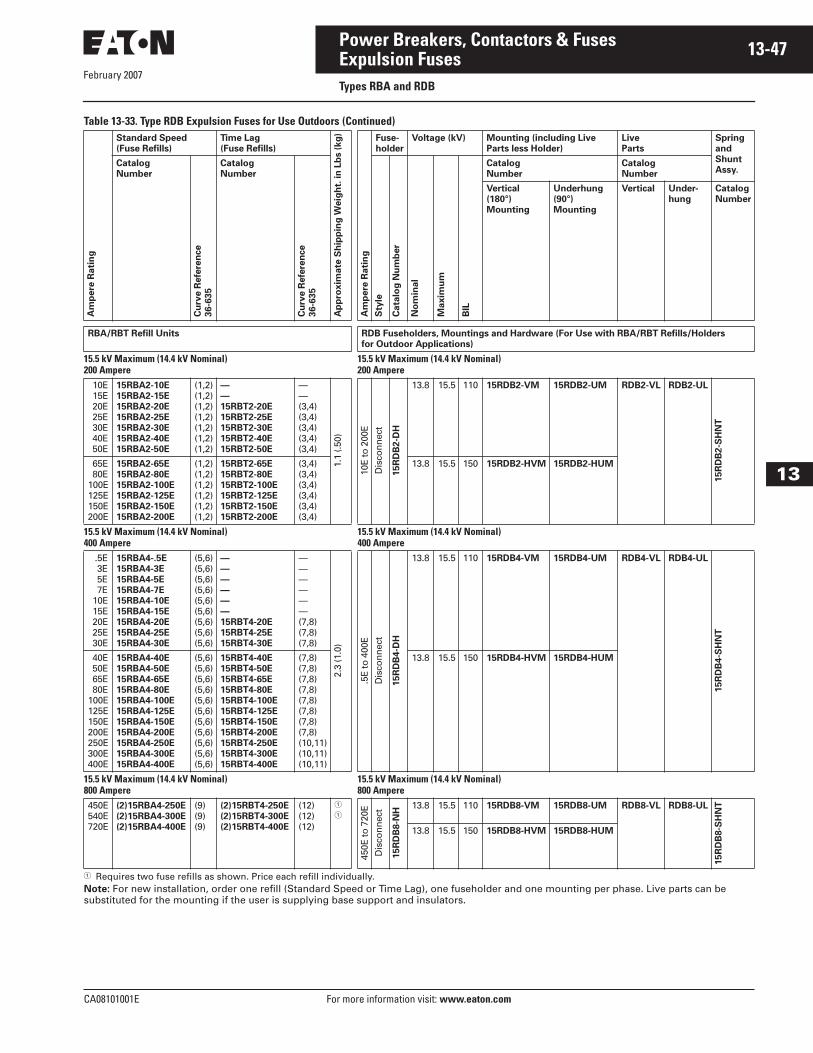
February 2007
CA08101001E For more information visit: www.eaton.com
13-47Power Breakers, Contactors & Fuses
13
Expulsion FusesTypes RBA and RDB
Table 13-33. Type RDB Expulsion Fuses for Use Outdoors (Continued)
� Requires two fuse refills as shown. Price each refill individually. Note: For new installation, order one refill (Standard Speed or Time Lag), one fuseholder and one mounting per phase. Live parts can be substituted for the mounting if the user is supplying base support and insulators.
Am
pere
Rati
ng
Standard Speed
(Fuse Refills)
Time Lag
(Fuse Refills)
Ap
pro
xim
ate
Sh
ipp
ing
Weig
ht.
in
Lb
s (
kg
)
Am
pere
Rati
ng
Fuse-
holder
Voltage (kV) Mounting (including Live
Parts less Holder)
Live
Parts
Spring
and
Shunt
Assy.Catalog
Number
Cu
rve R
efe
ren
ce
36-6
35
Catalog
Number
Cu
rve R
efe
ren
ce
36-6
35
Sty
le
Cata
log
Nu
mb
er
No
min
al
Maxim
um
BIL
Catalog
Number
Catalog
Number
Vertical
(180°)
Mounting
Underhung
(90°)
Mounting
Vertical Under-
hung
Catalog
Number
RBA/RBT Refill Units RDB Fuseholders, Mountings and Hardware (For Use with RBA/RBT Refills/Holders
for Outdoor Applications)
15.5 kV Maximum (14.4 kV Nominal)200 Ampere
15.5 kV Maximum (14.4 kV Nominal)200 Ampere
10E 15E 20E 25E 30E 40E 50E
15RBA2-10E
15RBA2-15E
15RBA2-20E
15RBA2-25E
15RBA2-30E
15RBA2-40E
15RBA2-50E
(1,2)(1,2)(1,2)(1,2)(1,2)(1,2)(1,2)
—
—
15RBT2-20E
15RBT2-25E
15RBT2-30E
15RBT2-40E
15RBT2-50E
——(3,4)(3,4)(3,4)(3,4)(3,4)
1.1
(.50)
10E
to 2
00E
Dis
con
nec
t
15R
DB
2-D
H
13.8 15.5 110 15RDB2-VM 15RDB2-UM RDB2-VL RDB2-UL
15R
DB
2-S
HN
T
65E 80E100E125E150E200E
15RBA2-65E
15RBA2-80E
15RBA2-100E
15RBA2-125E
15RBA2-150E
15RBA2-200E
(1,2)(1,2)(1,2)(1,2)(1,2)(1,2)
15RBT2-65E
15RBT2-80E
15RBT2-100E
15RBT2-125E
15RBT2-150E
15RBT2-200E
(3,4)(3,4)(3,4)(3,4)(3,4)(3,4)
13.8 15.5 150 15RDB2-HVM 15RDB2-HUM
15.5 kV Maximum (14.4 kV Nominal)400 Ampere
15.5 kV Maximum (14.4 kV Nominal)400 Ampere
.5E 3E 5E 7E 10E 15E 20E 25E 30E
15RBA4-.5E
15RBA4-3E
15RBA4-5E
15RBA4-7E
15RBA4-10E
15RBA4-15E
15RBA4-20E
15RBA4-25E
15RBA4-30E
(5,6)(5,6)(5,6)(5,6)(5,6)(5,6)(5,6)(5,6)(5,6)
—
—
—
—
—
—
15RBT4-20E
15RBT4-25E
15RBT4-30E
——————(7,8)(7,8)(7,8)
2.3
(1.0
)
.5E
to 4
00E
Dis
con
nec
t
15R
DB
4-D
H
13.8 15.5 110 15RDB4-VM 15RDB4-UM RDB4-VL RDB4-UL
15R
DB
4-S
HN
T
40E 50E 65E 80E100E125E150E200E250E300E400E
15RBA4-40E
15RBA4-50E
15RBA4-65E
15RBA4-80E
15RBA4-100E
15RBA4-125E
15RBA4-150E
15RBA4-200E
15RBA4-250E
15RBA4-300E
15RBA4-400E
(5,6)(5,6)(5,6)(5,6)(5,6)(5,6)(5,6)(5,6)(5,6)(5,6)(5,6)
15RBT4-40E
15RBT4-50E
15RBT4-65E
15RBT4-80E
15RBT4-100E
15RBT4-125E
15RBT4-150E
15RBT4-200E
15RBT4-250E
15RBT4-300E
15RBT4-400E
(7,8)(7,8)(7,8)(7,8)(7,8)(7,8)(7,8)(7,8)(10,11)(10,11)(10,11)
13.8 15.5 150 15RDB4-HVM 15RDB4-HUM
15.5 kV Maximum (14.4 kV Nominal)800 Ampere
15.5 kV Maximum (14.4 kV Nominal)800 Ampere
450E540E720E
(2)15RBA4-250E
(2)15RBA4-300E
(2)15RBA4-400E
(9)(9)(9)
(2)15RBT4-250E
(2)15RBT4-300E
(2)15RBT4-400E
(12)(12)(12)
�
�
450E
to 7
20E
Dis
con
nec
t
15R
DB
8-N
H
13.8 15.5 110 15RDB8-VM 15RDB8-UM RDB8-VL RDB8-UL
15R
DB
8-S
HN
T
13.8 15.5 150 15RDB8-HVM 15RDB8-HUM

February 2007
13-48
For more information visit: www.eaton.com CA08101001E
Power Breakers, Contactors & Fuses
13
Expulsion FusesTypes RBA and RDB
Table 13-33. Type RDB Expulsion Fuses for Use Outdoors (Continued)
� Requires two fuse refills as shown. Price each refill individually. Note: For new installation, order one refill (Standard Speed or Time Lag), one fuseholder and one mounting per phase. Live parts can be substituted for the mounting if the user is supplying base support and insulators.
Am
pere
Rati
ng
Standard Speed
(Fuse Refills)
Time Lag
(Fuse Refills)
Ap
pro
xim
ate
Sh
ipp
ing
Weig
ht.
in
Lb
s (
kg
)
Am
pere
Rati
ng
Fuse-
holder
Voltage (kV) Mounting (including Live
Parts less Holder)
Live
Parts
Spring
and
Shunt
Assy.Catalog
NumberC
urv
e R
efe
ren
ce
36-6
35
Catalog
Number
Cu
rve R
efe
ren
ce
36-6
35
Sty
le
Cata
log
Nu
mb
er
No
min
al
Maxim
um
BIL
Catalog
Number
Catalog
Number
Vertical
(180°)
Mounting
Underhung
(90°)
Mounting
Vertical Under-
hung
Catalog
Number
RBA/RBT Refill Units RDB Fuseholders, Mountings and Hardware (For Use with RBA/RBT Refills/Holders for
Outdoor Applications)
25.5 kV Maximum (23.0 kV Nominal)200 Ampere
25.5 kV Maximum (23.0 kV Nominal)200 Ampere
10E 15E 20E 25E 30E 40E 50E
25RBA2-10E
25RBA2-15E
25RBA2-20E
25RBA2-25E
25RBA2-30E
25RBA2-40E
25RBA2-50E
(1,2)(1,2)(1,2)(1,2)(1,2)(1,2)(1,2)
—
—
25RBT2-20E
25RBT2-25E
25RBT2-30E
25RBT2-40E
25RBT2-50E
——(3,4)(3,4)(3,4)(3,4)(3,4)
1.3
(.6)
10E
to 2
00E
Dis
con
nec
t
25R
DB
2-D
H
23.0 25.5 150 25RDB2-VM 25RDB2-UM RDB2-VL RDB2-UL
25R
DB
2-S
HN
T
65E 80E100E125E150E200E
25RBA2-65E
25RBA2-80E
25RBA2-100E
25RBA2-125E
25RBA2-150E
25RBA2-200E
(1,2)(1,2)(1,2)(1,2)(1,2)(1,2)
25RBT2-65E
25RBT2-80E
25RBT2-100E
25RBT2-125E
25RBT2-150E
25RBT2-200E
(3,4)(3,4)(3,4)(3,4)(3,4)(3,4)
23.0 25.5 200 25RDB2-HVM 25RDB2-HUM
25.5 kV Maximum (23.0 kV Nominal)400 Ampere
25.5 kV Maximum (23.0 kV Nominal)400 Ampere
.5E 3E 5E 7E 10E 15E 20E 25E 30E
25RBA4-.5E
25RBA4-3E
25RBA4-5E
25RBA4-7E
25RBA4-10E
25RBA4-15E
25RBA4-20E
25RBA4-25E
25RBA4-30E
(5,6)(5,6)(5,6)(5,6)(5,6)(5,6)(5,6)(5,6)(5,6)
—
—
—
—
—
—
25RBT4-20E
25RBT4-25E
25RBT4-30E
——————(7,8)(7,8)(7,8)
2.7
(1.2
)
.5E
to 3
00E
Dis
con
nec
t
25R
DB
4-D
H
23.0 25.5 150 25RDB4-VM 25RDB4-UM RDB4-VL RDB4-UL
25R
DB
4-S
HN
T
40E 50E 65E 80E100E125E150E200E250E300E
25RBA4-40E
25RBA4-50E
25RBA4-65E
25RBA4-80E
25RBA4-100E
25RBA4-125E
25RBA4-150E
25RBA4-200E
25RBA4-250E
25RBA4-300E
(5,6)(5,6)(5,6)(5,6)(5,6)(5,6)(5,6)(5,6)(5,6)(5,6)
25RBT4-40E
25RBT4-50E
25RBT4-65E
25RBT4-80E
25RBT4-100E
25RBT4-125E
25RBT4-150E
25RBT4-200E
25RBT4-250E
25RBT4-300E
(7,8)(7,8)(7,8)(7,8)(7,8)(7,8)(7,8)(7,8)(10,11)(10,11)
23.0 25.5 200 25RDB4-HVM 25RDB4-HUM
25.5 kV Maximum (23.0 kV Nominal)800 Ampere
25.5 kV Maximum (23.0 kV Nominal)800 Ampere
450E540E
(2)25RBA4-250E
(2)25RBA4-300E
(9)(9)
(2)25RBT4-250E
(2)25RBT4-300E
(12)(12)
�
�
450E
to 5
40E
Dis
con
nec
t
25R
DB
8-N
H
23.0 25.5 150 25RDB8-VM 25RDB8-UM RDB8-VL RDB8-UL
25R
DB
8-S
HN
T
23.0 25.5 200 25RDB8-HVM 25RDB8-HUM

February 2007
CA08101001E For more information visit: www.eaton.com
13-49Power Breakers, Contactors & Fuses
13
Expulsion FusesTypes RBA and RDB
Table 13-34. Type RBA Expulsion Fuses for Use Indoors or in an Enclosure
� Requires two fuse refills as shown. Price each refill individually. Note: For new installation, order one refill (Standard Speed or Time Lag), one fuseholder and one mounting per phase. Live parts can be substituted for the mounting if the user is supplying base support and insulators.
Am
pere
Rati
ng
Standard Speed
(Fuse Refills)
Time Lag
(Fuse Refills)
Ap
pro
xim
ate
Sh
ipp
ing
Weig
ht.
in
Lb
s (
kg
)
Am
pere
Rati
ng
Fuse-
holder
Voltage (kV) Mounting (including Live
Parts less Holder)
Live
Parts
Spring
and
Shunt
Assy.Catalog
Number
Cu
rve R
efe
ren
ce
36-6
35
Catalog
Number
Cu
rve R
efe
ren
ce
36-6
35
Sty
le
Cata
log
Nu
mb
er
No
min
al
Maxim
um
BIL
Catalog
Number
Catalog
Number
Vertical
(180°)
Mounting
Underhung
(90°)
Mounting
Vertical Under-
hung
Catalog
Number
RBA/RBT Refill Units RDB Fuseholders, Mountings and Hardware (For Use with RBA/RBT Refills/Holders for
Outdoor Applications)
38.0 kV Maximum (34.5 kV Nominal)200 Ampere
38.0 kV Maximum (34.5 kV Nominal)200 Ampere
10E 15E 20E 25E 30E 40E 50E
38RBA2-10E
38RBA2-15E
38RBA2-20E
38RBA2-25E
38RBA2-30E
38RBA2-40E
38RBA2-50E
(1,2)(1,2)(1,2)(1,2)(1,2)(1,2)(1,2)
—
—
38RBT2-20E
38RBT2-25E
38RBT2-30E
38RBT2-40E
38RBT2-50E
——(3,4)(3,4)(3,4)(3,4)(3,4)
1.4
(.6)
10E
to 2
00E
Dis
con
nec
t
38R
DB
2-D
H
34.5 38.0 200 38RDB2-VM 38RDB2-UM RDB2-VL RDB2-UL
38R
DB
2-S
HN
T
65E 80E100E125E150E200E
38RBA2-65E
38RBA2-80E
38RBA2-100E
38RBA2-125E
38RBA2-150E
38RBA2-200E
(1,2)(1,2)(1,2)(1,2)(1,2)(1,2)
38RBT2-65E
38RBT2-80E
38RBT2-100E
38RBT2-125E
38RBT2-150E
38RBT2-200E
(3,4)(3,4)(3,4)(3,4)(3,4)(3,4)
34.5 38.0 250 38RDB2-HVM 38RDB2-HUM
38.0 kV Maximum (34.5 kV Nominal)400 Ampere
38.0 kV Maximum (34.5 kV Nominal)400 Ampere
.5E 3E 5E 7E 10E 15E 20E 25E 30E
38RBA4-.5E
38RBA4-3E
38RBA4-5E
38RBA4-7E
38RBA4-10E
38RBA4-15E
38RBA4-20E
38RBA4-25E
38RBA4-30E
(5,6)(5,6)(5,6)(5,6)(5,6)(5,6)(5,6)(5,6)(5,6)
—
—
—
—
—
—
38RBT4-20E
38RBT4-25E
38RBT4-30E
——————(7,8)(7,8)(7,8)
3.1
(1.4
)
.5E
to 3
00E
Dis
con
nec
t
38R
DB
4-D
H
34.5 38.0 150 38RDB4-VM 38RDB4-UM RDB4-VL RDB4-UL
38R
DB
4-S
HN
T
40E 50E 65E 80E100E125E150E200E250E300E
38RBA4-40E
38RBA4-50E
38RBA4-65E
38RBA4-80E
38RBA4-100E
38RBA4-125E
38RBA4-150E
38RBA4-200E
38RBA4-250E
38RBA4-300E
(5,6)(5,6)(5,6)(5,6)(5,6)(5,6)(5,6)(5,6)(5,6)(5,6)
38RBT4-40E
38RBT4-50E
38RBT4-65E
38RBT4-80E
38RBT4-100E
38RBT4-125E
38RBT4-150E
38RBT4-200E
38RBT4-250E
38RBT4-300E
(7,8)(7,8)(7,8)(7,8)(7,8)(7,8)(7,8)(7,8)(10,11)(10,11)
34.5 38.0 200 38RDB4-HVM 38RDB4-HUM
38.0 kV Maximum (34.5 kV Nominal)800 Ampere
38.0 kV Maximum (34.5 kV Nominal)800 Ampere
450E540E
(2)38RBA4-250E
(2)38RBA4-300E
(9)(9)
(2)38RBT4-250E
(2)38RBT4-300E
(12)(12)
�
�
450E
to 5
40E
Dis
con
nec
t
38R
DB
8-N
H
34.5 38.0 150 38RDB8-VM 38RDB8-UM RDB8-VL RDB8-UL
38R
DB
8-S
HN
T
34.5 38.0 200 38RDB8-HVM 38RDB8-HUM
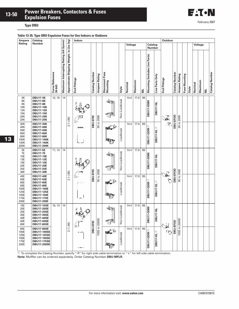
February 2007
13-50
For more information visit: www.eaton.com CA08101001E
Power Breakers, Contactors & Fuses
13
Expulsion FusesType DBU
Table 13-35. Type DBU Expulsion Fuses for Use Indoors or Outdoors
� To complete the Catalog Number, specify “-R” for right side cable termination or “-L” for left side cable termination.Note: Muffler can be ordered separately. Order Catalog Number DBU-MFLR.
Ampere
Rating
Catalog
Number
Cu
rve R
efe
ren
ce
36-6
43
Maxim
um
In
terr
up
tin
g R
ati
ng
(kA
Sym
m)
Ap
pro
xim
ate
Sh
ipp
ing
Weig
ht.
in
Lb
s (
kg
)
Indoor Outdoor
En
d F
itti
ng
s
Cata
log
Nu
mb
er
Am
pere
Rati
ng
Dis
co
nn
ect
Fu
se
Mo
un
tin
g
Sty
le
Voltage Catalog
Number
En
d F
itti
ng
s
Cata
log
Nu
mb
er
Am
pere
Rati
ng
Fu
se M
ou
nti
ng
Sty
le
Voltage
Cata
log
Nu
mb
er
No
min
al
Maxim
um
BIL
Mo
un
tin
g (
Inclu
des L
ive P
art
s)
Liv
e P
art
s O
nly
No
min
al
Maxim
um
BIL
3K 6K 8K 10K 12K 15K 20K 25K
DBU17-3K
DBU17-6K
DBU17-8K
DBU17-10K
DBU17-12K
DBU17-15K
DBU17-20K
DBU17-25K
12, 15 14
2.1
(.95)
DB
U-E
FID
3K to
200
K No
n-L
oad
bre
ak
14.4 17.0 95
DB
U17-G
NM
DB
U17-N
L
DB
U-E
FO
D
3K to
200
K
30K 40K 50K 65K 80K100K140K200K
DBU17-30K
DBU17-40K
DBU17-50K
DBU17-65K
DBU17-80K
DBU17-100K
DBU17-140K
DBU17-200K
Load
bre
ak14.4 17.0 95
DB
U17-G
DM
�
DB
U17-D
L �
5E 7E 10E 13E 15E 20E 25E 30E
DBU17-5E
DBU17-7E
DBU17-10E
DBU17-13E
DBU17-15E
DBU17-20E
DBU17-25E
DBU17-30E
11, 14 14
2.1
(.95)
DB
U-E
FID
5E to
200
E No
n-L
oad
bre
ak
14.4 17.0 95D
BU
17-G
NM
DB
U17-N
L
DB
U-E
FO
D
5E to
200
E 40E 50E 65E 80E100E125E150E175E200E
DBU17-40E
DBU17-50E
DBU17-65E
DBU17-80E
DBU17-100E
DBU17-125E
DBU17-150E
DBU17-175E
DBU17-200E
Load
bre
ak
14.4 17.0 95
DB
U17-G
DM
�
DB
U17-D
L �
15E 20E 25E 30E 40E 50E 65E
DBU17-15SE
DBU17-20SE
DBU17-25SE
DBU17-30SE
DBU17-40SE
DBU17-50SE
DBU17-65SE
10, 13 14
2.1
(.95)
DB
U-E
FID
15S
E to
200
SE
No
n-L
oad
bre
ak 14.4 17.0 95
DB
U17-G
NM
DB
U17-N
L
DB
U-E
FO
D
15S
E to
200
SE
80E100E125E150E175E200E
DBU17-80SE
DBU17-100SE
DBU17-125SE
DBU17-150SE
DBU17-175SE
DBU17-200SE Load
bre
ak
14.4 17.0 95
DB
U17-G
DM
�
DB
U17-D
L �
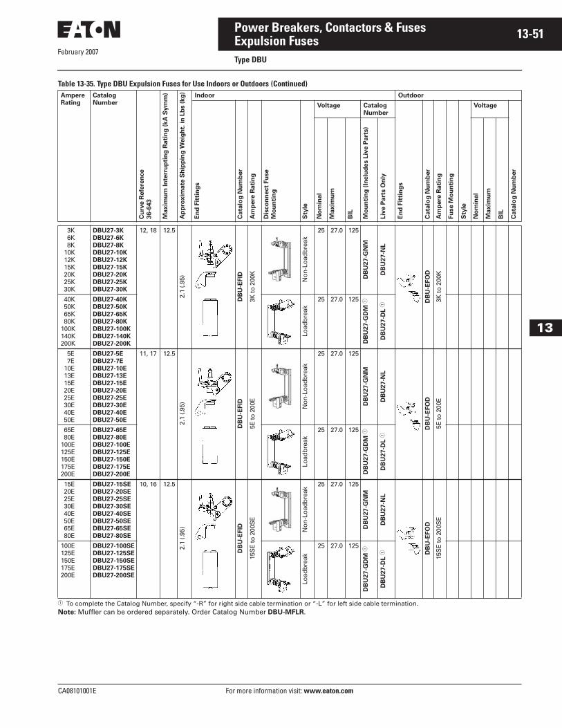
February 2007
CA08101001E For more information visit: www.eaton.com
13-51Power Breakers, Contactors & Fuses
13
Expulsion FusesType DBU
Table 13-35. Type DBU Expulsion Fuses for Use Indoors or Outdoors (Continued)
� To complete the Catalog Number, specify “-R” for right side cable termination or “-L” for left side cable termination.Note: Muffler can be ordered separately. Order Catalog Number DBU-MFLR.
Ampere
Rating
Catalog
Number
Cu
rve R
efe
ren
ce
36-6
43
Maxim
um
In
terr
up
tin
g R
ati
ng
(kA
Sym
m)
Ap
pro
xim
ate
Sh
ipp
ing
Weig
ht.
in
Lb
s (
kg
)
Indoor Outdoor
En
d F
itti
ng
s
Cata
log
Nu
mb
er
Am
pere
Rati
ng
Dis
co
nn
ect
Fu
se
Mo
un
tin
g
Sty
le
Voltage Catalog
Number
En
d F
itti
ng
s
Cata
log
Nu
mb
er
Am
pere
Rati
ng
Fu
se M
ou
nti
ng
Sty
le
Voltage
Cata
log
Nu
mb
er
No
min
al
Maxim
um
BIL
Mo
un
tin
g (
Inclu
des L
ive P
art
s)
Liv
e P
art
s O
nly
No
min
al
Maxim
um
BIL
3K 6K 8K 10K 12K 15K 20K 25K 30K
DBU27-3K
DBU27-6K
DBU27-8K
DBU27-10K
DBU27-12K
DBU27-15K
DBU27-20K
DBU27-25K
DBU27-30K
12, 18 12.5
2.1
(.95)
DB
U-E
FID
3K to
200
K
No
n-L
oad
bre
ak
25 27.0 125
DB
U27-G
NM
DB
U27-N
L
DB
U-E
FO
D
3K to
200
K
40K 50K 65K 80K100K140K200K
DBU27-40K
DBU27-50K
DBU27-65K
DBU27-80K
DBU27-100K
DBU27-140K
DBU27-200K
Load
bre
ak25 27.0 125
DB
U27-G
DM
�
DB
U27-D
L �
5E 7E 10E 13E 15E 20E 25E 30E 40E 50E
DBU27-5E
DBU27-7E
DBU27-10E
DBU27-13E
DBU27-15E
DBU27-20E
DBU27-25E
DBU27-30E
DBU27-40E
DBU27-50E
11, 17 12.5
2.1
(.95)
DB
U-E
FID
5E to
200
E
No
n-L
oad
bre
ak
25 27.0 125
DB
U27-G
NM
DB
U27-N
L
DB
U-E
FO
D
5E to
200
E 65E 80E100E125E150E175E200E
DBU27-65E
DBU27-80E
DBU27-100E
DBU27-125E
DBU27-150E
DBU27-175E
DBU27-200E
Load
bre
ak
25 27.0 125
DB
U27-G
DM
�
DB
U27-D
L �
15E 20E 25E 30E 40E 50E 65E 80E
DBU27-15SE
DBU27-20SE
DBU27-25SE
DBU27-30SE
DBU27-40SE
DBU27-50SE
DBU27-65SE
DBU27-80SE
10, 16 12.5
2.1
(.95)
DB
U-E
FID
15S
E to
200
SE
No
n-L
oad
bre
ak
25 27.0 125
DB
U27-G
NM
DB
U27-N
L
DB
U-E
FO
D
15S
E to
200
SE
100E125E150E175E200E
DBU27-100SE
DBU27-125SE
DBU27-150SE
DBU27-175SE
DBU27-200SE
Load
bre
ak
25 27.0 125
DB
U27-G
DM
�
DB
U27-D
L �

February 2007
13-52
For more information visit: www.eaton.com CA08101001E
Power Breakers, Contactors & Fuses
13
Expulsion FusesType DBU
Table 13-35. Type DBU Expulsion Fuses for Use Indoors or Outdoors (Continued)
Note: Muffler can be ordered separately. Order Catalog Number DBU-MFLR.
Ampere
Rating
Catalog
Number
Cu
rve R
efe
ren
ce
36-6
43
Maxim
um
In
terr
up
tin
g R
ati
ng
kA
Sym
.
Ap
pro
xim
ate
Sh
ipp
ing
Weig
ht.
in
Lb
s (
kg
)
Indoor Outdoor
En
d F
itti
ng
s
Cata
log
Nu
mb
er
Am
pere
Rati
ng
Dis
co
nn
ect
Fu
se
Mo
un
tin
g
Sty
le
Voltage Catalog
Number
En
d F
itti
ng
s
Cata
log
Nu
mb
er
Am
pere
Rati
ng
Fu
se M
ou
nti
ng
Sty
le
Voltage
Cata
log
Nu
mb
er
No
min
al
Maxim
um
BIL
Mo
un
tin
g (
Inclu
de L
ive P
art
s)
Liv
e P
art
s O
nly
No
min
al
Maxim
um
BIL
3K 6K 8K 10K 12K 15K 20K 25K
DBU38-3K
DBU38-6K
DBU38-8K
DBU38-10K
DBU38-12K
DBU38-15K
DBU38-20K
DBU38-25K
12, 18 10
2.8
(1.3
)
DB
U-E
FID
3K to
200
K No
n-L
oad
bre
ak
34.5 38.0 150
DB
U38-G
NM
DB
U38-N
L
DB
U-E
FO
D
3K to
200
K
30K 40K 50K 65K 80K100K140K200K
DBU38-30K
DBU38-40K
DBU38-50K
DBU38-65K
DBU38-80K
DBU38-100K
DBU38-140K
DBU38-200K
Load
bre
ak34.5 38.0 150
5E 7E 10E 13E 15E 20E 25E 30E 40E 50E
DBU38-5E
DBU38-7E
DBU38-10E
DBU38-13E
DBU38-15E
DBU38-20E
DBU38-25E
DBU38-30E
DBU38-40E
DBU38-50E
11, 17 10
2.8
(1.3
)
DB
U-E
FID
5E to
200
E
No
n-L
oad
bre
ak
34.5 38.0 150D
BU
38-G
NM
DB
U38-N
L
DB
U-E
FO
D
5E to
200
E 65E 80E100E125E150E175E200E
DBU38-65E
DBU38-80E
DBU38-100E
DBU38-125E
DBU38-150E
DBU38-175E
DBU38-200E
Load
bre
ak
34.5 38.0 150
15E 20E 25E 30E 40E 50E 65E 80E
DBU38-15SE
DBU38-20SE
DBU38-25SE
DBU38-30SE
DBU38-40SE
DBU38-50SE
DBU38-65SE
DBU38-80SE
10, 16 10
2.1
(.95)
DB
U-E
FID
15S
E to
200
SE
No
n-L
oad
bre
ak
34.5 38.0 150
DB
U38-G
NM
DB
U38-N
L
DB
U-E
FO
D
15S
E to
200
SE
100E125E150E175E200E
DBU38-100SE
DBU38-125SE
DBU38-150SE
DBU38-175SE
DBU38-200SE
Load
bre
ak
34.5 38.0 150
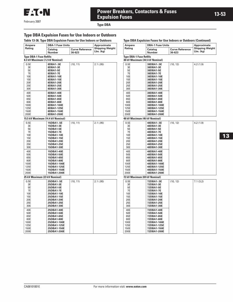
February 2007
CA08101001E For more information visit: www.eaton.com
13-53Power Breakers, Contactors & Fuses
13
Expulsion FusesType DBA
Type DBA Expulsion Fuses for Use Indoors or OutdoorsTable 13-36. Type DBA Expulsion Fuses for Use Indoors or Outdoors Type DBA Expulsion Fuses for Use Indoors or Outdoors (Continued)Ampere
Rating
DBA-1 Fuse Units Approximate
Shipping Weight
Lbs. (kg)Catalog
Number
Curve Reference
36-623
Type DBA-1 Fuse Refills8.3 kV Maximum (7.2 kV Nominal) 0.5E 3E 5E 7E 10E 15E 20E 25E 30E
8DBA1-.5E
8DBA1-3E
8DBA1-5E
8DBA1-7E
8DBA1-10E
8DBA1-15E
8DBA1-20E
8DBA1-25E
8DBA1-30E
(10, 11) 2.1 (.95)
40E 50E 65E 80E100E125E150E200E
8DBA1-40E
8DBA1-50E
8DBA1-65E
8DBA1-80E
8DBA1-100E
8DBA1-125E
8DBA1-150E
8DBA1-200E
15.5 kV Maximum (14.4 kV Nominal) 0.5E 3E 5E 7E 10E 15E 20E 25E 30E
15DBA1-.5E
15DBA1-3E
15DBA1-5E
15DBA1-7E
15DBA1-10E
15DBA1-15E
15DBA1-20E
15DBA1-25E
15DBA1-30E
(10, 11) 2.1 (.95)
40E 50E 65E 80E100E125E150E200E
15DBA1-40E
15DBA1-50E
15DBA1-65E
15DBA1-80E
15DBA1-100E
15DBA1-125E
15DBA1-150E
15DBA1-200E
25 kV Maximum (23 kV Nominal) 0.5E 3E 5E 7E 10E 15E 20E 25E 30E
25DBA1-.5E
25DBA1-3E
25DBA1-5E
25DBA1-7E
25DBA1-10E
25DBA1-15E
25DBA1-20E
25DBA1-25E
25DBA1-30E
(10, 11) 2.1 (.95)
40E 50E 65E 80E100E125E150E200E
25DBA1-40E
25DBA1-50E
25DBA1-65E
25DBA1-80E
25DBA1-100E
25DBA1-125E
25DBA1-150E
25DBA1-200E
Ampere
Rating
DBA-1 Fuse Units Approximate
Shipping Weight
Lbs. (kg)Catalog
Number
Curve Reference
36-623
Type DBA-1 Fuse Refills38 kV Maximum (34.5 kV Nominal) 0.5E 3E 5E 7E 10E 15E 20E 25E 30E
38DBA1-.5E
38DBA1-3E
38DBA1-5E
38DBA1-7E
38DBA1-10E
38DBA1-15E
38DBA1-20E
38DBA1-25E
38DBA1-30E
(10, 12) 4.2 (1.9)
40E 50E 65E 80E100E125E150E200E
38DBA1-40E
38DBA1-50E
38DBA1-65E
38DBA1-80E
38DBA1-100E
38DBA1-125E
38DBA1-150E
38DBA1-200E
48 kV Maximum (46 kV Nominal) 0.5E 3E 5E 7E 10E 15E 20E 25E 30E
48DBA1-.5E
48DBA1-3E
48DBA1-5E
48DBA1-7E
48DBA1-10E
48DBA1-15E
48DBA1-20E
48DBA1-25E
48DBA1-30E
(10, 12) 4.2 (1.9)
40E 50E 65E 80E100E125E150E200E
48DBA1-40E
48DBA1-50E
48DBA1-65E
48DBA1-80E
48DBA1-100E
48DBA1-125E
48DBA1-150E
48DBA1-200E
72 kV Maximum (69 kV Nominal) 0.5E 3E 5E 7E 10E 15E 20E 25E 30E
72DBA1-.5E
72DBA1-3E
72DBA1-5E
72DBA1-7E
72DBA1-10E
72DBA1-15E
72DBA1-20E
72DBA1-25E
72DBA1-30E
(10, 12) 7.1 (3.2)
40E 50E 65E 80E100E125E150E200E
72DBA1-40E
72DBA1-50E
72DBA1-65E
72DBA1-80E
72DBA1-100E
72DBA1-125E
72DBA1-150E
72DBA1-200E
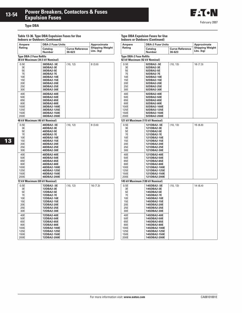
February 2007
13-54
For more information visit: www.eaton.com CA08101001E
Power Breakers, Contactors & Fuses
13
Expulsion FusesType DBA
Table 13-36. Type DBA Expulsion Fuses for Use Indoors or Outdoors (Continued)
Type DBA Expulsion Fuses for Use Indoors or Outdoors (Continued)
Ampere
Rating
DBA-2 Fuse Units Approximate
Shipping Weight
Lbs. (kg)Catalog
Number
Curve Reference
36-623
Type DBA-2 Fuse Refills38 kV Maximum (34.5 kV Nominal) 0.5E 3E 5E 7E 10E 15E 20E 25E 30E
38DBA2-.5E
38DBA2-3E
38DBA2-5E
38DBA2-7E
38DBA2-10E
38DBA2-15E
38DBA2-20E
38DBA2-25E
38DBA2-30E
(10, 12) 8 (3.6)
40E 50E 65E 80E100E125E150E200E
38DBA2-40E
38DBA2-50E
38DBA2-65E
38DBA2-80E
38DBA2-100E
38DBA2-125E
38DBA2-150E
38DBA2-200E
48 kV Maximum (46 kV Nominal) 0.5E 3E 5E 7E 10E 15E 20E 25E 30E
48DBA2-.5E
48DBA2-3E
48DBA2-5E
48DBA2-7E
48DBA2-10E
48DBA2-15E
48DBA2-20E
48DBA2-25E
48DBA2-30E
(10, 12) 8 (3.6)
40E 50E 65E 80E100E125E150E200E
48DBA2-40E
48DBA2-50E
48DBA2-65E
48DBA2-80E
48DBA2-100E
48DBA2-125E
48DBA2-150E
48DBA2-200E
72 kV Maximum (69 kV Nominal) 0.5E 3E 5E 7E 10E 15E 20E 25E 30E
72DBA2-.5E
72DBA2-3E
72DBA2-5E
72DBA2-7E
72DBA2-10E
72DBA2-15E
72DBA2-20E
72DBA2-25E
72DBA2-30E
(10, 12) 16 (7.3)
40E 50E 65E 80E100E125E150E200E
72DBA2-40E
72DBA2-50E
72DBA2-65E
72DBA2-80E
72DBA2-100E
72DBA2-125E
72DBA2-150E
72DBA2-200E
Ampere
Rating
DBA-2 Fuse Units Approximate
Shipping Weight
Lbs. (kg)Catalog
Number
Curve Reference
36-623
Type DBA-2 Fuse Refills92 kV Maximum (92 kV Nominal) 0.5E 3E 5E 7E 10E 15E 20E 25E 30E
92DBA2-.5E
92DBA2-3E
92DBA2-5E
92DBA2-7E
92DBA2-10E
92DBA2-15E
92DBA2-20E
92DBA2-25E
92DBA2-30E
(10, 13) 16 (7.3)
40E 50E 65E 80E100E125E150E200E
92DBA2-40E
92DBA2-50E
92DBA2-65E
92DBA2-80E
92DBA2-100E
92DBA2-125E
92DBA2-150E
92DBA2-200E
121 kV Maximum (115 kV Nominal) 0.5E 3E 5E 7E 10E 15E 20E 25E 30E
121DBA2-.5E
121DBA2-3E
121DBA2-5E
121DBA2-7E
121DBA2-10E
121DBA2-15E
121DBA2-20E
121DBA2-25E
121DBA2-30E
(10, 13) 15 (6.8)
40E 50E 65E 80E100E125E150E200E
121DBA2-40E
121DBA2-50E
121DBA2-65E
121DBA2-80E
121DBA2-100E
121DBA2-125E
121DBA2-150E
121DBA2-200E
145 kV Maximum (138 kV Nominal) 0.5E 3E 5E 7E 10E 15E 20E 25E 30E
145DBA2-.5E
145DBA2-3E
145DBA2-5E
145DBA2-7E
145DBA2-10E
145DBA2-15E
145DBA2-20E
145DBA2-25E
145DBA2-30E
(10, 13) 14 (6.4)
40E 50E 65E 80E100E125E150E200E
145DBA2-40E
145DBA2-50E
145DBA2-65E
145DBA2-80E
145DBA2-100E
145DBA2-125E
145DBA2-150E
145DBA2-200E

February 2007
CA08101001E For more information visit: www.eaton.com
13-55Power Breakers, Contactors & Fuses
13
Current Limiting FusesProduct Selection
Current Limiting Fuse
Easy to Use, Easy to Order!Eaton’s Cutler-Hammer fuse catalog numbering system makes it easy to order the right fuse. The catalog num-bers are easy to remember, unique to each fuse, and are broken down in three descriptive segments: Fuse Type, Voltage Rating and Current Rating.
These Catalog Numbers can be entered directly and easily:
■ No change in order processing will occur if you use either a style num-ber or its corresponding catalog number. You will get the same fuse.
■ In the back of this ordering guide is a style number to catalog number cross reference chart.
Examples:5CLE-30E 5.5 max. kV,
CLE fuse unit,30E amperes
15CXN-45C 15.5 max. kV,CXN fuse unit,45C amperes
5CLS-GDM-E 5.5 max. kV,CLS fuse unit,Glass PolyesterNondisconnectMounting
CLE-DL-D CLE,Disconnect Live PartsSize D
Table 13-37. Current Limiting Fuses Catalog Numbering System
Table 13-38. Current Limiting Fuse Accessories Catalog Numbering System
15 CLE – 100 E – D
Amperes
0.5 – 1350
Size
A
D
Class
E
R
C
X
Maximum kV
2 = (2.4, 2.5, 2.75) 4 = (4.3, 4.8) 5 = (5.08, 5.5) 7 = (7.2) 8 = (8.3)15 = (15.5)25 = (25.5)38 = (38.0)
Type
CLE HCLS
HLE LCLS
BHLE CX
CLPT CXN
NCLPT CLT
CLS AHLE
BCLS CXF
CLS70 ACLS
CLS75
15 CLE – P NM – C
Insulator
G = Glass PolyesterP = PorcelainH = High BIL
Diameter Size
A = 1-5/8 inches(41.3 mm)0.53E – 1.5ESingle Barrel
B = 1-5/8 inches(41.3 mm) 3E– 10E SingleBarrel
C = 2-inch (50.8mm) SingleBarrel
D = 3-inch (76.2mm) SingleBarrel
E = 3-inch (76.2mm) DoubleBarrel
F = 4-inch (101.6mm) DoubleBarrel
G = 5/8-inch (15.9mm) Ferrule(CX/CXNOnly)
Hardware
DM = Disconnect Mounting
NM = NondisconnectMounting
DL = DisconnectLive Parts
NL = NondisconnectLive Parts
DF = Disconnect End Fittings
Maximum kV
2 = (2.4, 2.5, 2.75) 4 = (4.3, 4.8) 5 = (5.08, 5.5) 7 = (7.2) 8 = (8.3)15 = (15.5)25 = (25.5)38 = (38.0)
Type
CLE HCLS
HLE LCLS
CLPT CX
NCLPT CXN
CLS CLT
CLS75
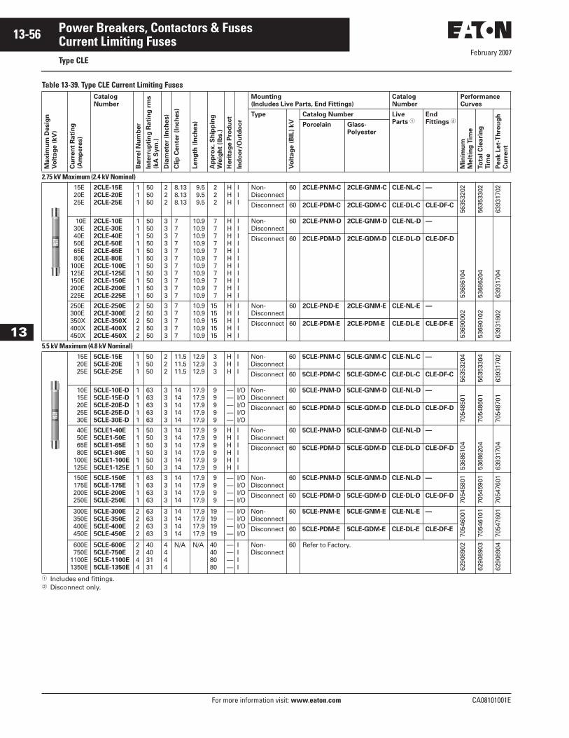
February 2007
13-56
For more information visit: www.eaton.com CA08101001E
Power Breakers, Contactors & Fuses
13
Current Limiting FusesType CLE
Table 13-39. Type CLE Current Limiting Fuses
� Includes end fittings.� Disconnect only.
Ma
xim
um
De
sig
n
Vo
lta
ge
(k
V)
Cu
rre
nt
Ra
tin
g
(Am
pe
res)
Catalog
Number
Ba
rre
l N
um
be
r
Inte
rru
pti
ng
Ra
tin
g r
ms
(kA
Sy
m.)
Dia
me
ter
(In
ch
es)
Clip
Ce
nte
r (I
nch
es)
Le
ng
th (
Inch
es)
Ap
pro
x. S
hip
pin
g
We
igh
t (l
bs.)
He
rita
ge
Pro
du
ct
Ind
oo
r/O
utd
oo
r
Mounting
(Includes Live Parts, End Fittings)
Catalog
Number
Performance
Curves
Type
Vo
lta
ge
(B
IL)
kV
Catalog Number Live
Parts �End
Fittings �
Min
imu
m
Me
ltin
g T
ime
To
tal C
lea
rin
g
Tim
e
Pe
ak
Le
t-T
hro
ug
h
Cu
rre
nt
Porcelain Glass-
Polyester
2.75 kV Maximum (2.4 kV Nominal) 15E 20E 25E
2CLE-15E
2CLE-20E
2CLE-25E
111
505050
222
8.138.138.13
9.5 9.5 9.5
2 2 2
HHH
III
Non-Disconnect
60 2CLE-PNM-C 2CLE-GNM-C CLE-NL-C —
5635
3202
5635
3302
6393
1702
Disconnect 60 2CLE-PDM-C 2CLE-GDM-C CLE-DL-C CLE-DF-C
10E 30E 40E 50E 65E 80E100E125E150E200E225E
2CLE-10E
2CLE-30E
2CLE-40E
2CLE-50E
2CLE-65E
2CLE-80E
2CLE-100E
2CLE-125E
2CLE-150E
2CLE-200E
2CLE-225E
11111111111
5050505050505050505050
33333333333
77777777777
10.910.910.910.910.910.910.910.910.910.910.9
7 7 7 7 7 7 7 7 7 7 7
HHHHHHHHHHH
IIIIIIIIIII
Non-Disconnect
60 2CLE-PNM-D 2CLE-GNM-D CLE-NL-D —
5368
6104
5368
6204
6393
1704
Disconnect 60 2CLE-PDM-D 2CLE-GDM-D CLE-DL-D CLE-DF-D
250E300E350X400X450X
2CLE-250E
2CLE-300E
2CLE-350X
2CLE-400X
2CLE-450X
22222
5050505050
33333
77777
10.910.910.910.910.9
1515151515
HHHHH
IIIII
Non-Disconnect
60 2CLE-PND-E 2CLE-GNM-E CLE-NL-E —
5369
0002
5369
0102
6393
1802
Disconnect 60 2CLE-PDM-E 2CLE-PDM-E CLE-DL-E CLE-DF-E
5.5 kV Maximum (4.8 kV Nominal) 15E 20E 25E
5CLE-15E
5CLE-20E
5CLE-25E
111
505050
222
11.511.511.5
12.912.912.9
3 3 3
HHH
III
Non-Disconnect
60 5CLE-PNM-C 5CLE-GNM-C CLE-NL-C —
5635
3204
5635
3304
6393
1702
Disconnect 60 5CLE-PDM-C 5CLE-GDM-C CLE-DL-C CLE-DF-C
10E 15E 20E 25E 30E
5CLE-10E-D
5CLE-15E-D
5CLE-20E-D
5CLE-25E-D
5CLE-30E-D
11111
6363636363
33333
1414141414
17.917.917.917.917.9
9 9 9 9 9
—————
I/OI/OI/OI/OI/O
Non-Disconnect
60 5CLE-PNM-D 5CLE-GNM-D CLE-NL-D —
7054
8501
7054
8601
7054
8701
Disconnect 60 5CLE-PDM-D 5CLE-GDM-D CLE-DL-D CLE-DF-D
40E 50E 65E 80E 100E 125E
5CLE1-40E
5CLE1-50E
5CLE1-65E
5CLE1-80E
5CLE1-100E
5CLE1-125E
111111
505050505050
333333
141414141414
17.917.917.917.917.917.9
9 9 9 9 9 9
HHHHHH
IIIIII
Non-Disconnect
60 5CLE-PNM-D 5CLE-GNM-D CLE-NL-D —
5368
6104
5368
6204
6393
1704Disconnect 60 5CLE-PDM-D 5CLE-GDM-D CLE-DL-D CLE-DF-D
150E 175E 200E 250E
5CLE-150E
5CLE-175E
5CLE-200E
5CLE-250E
1111
63636363
3333
14141414
17.917.917.917.9
9 9 9 9
————
I/OI/OI/OI/O
Non-Disconnect
60 5CLE-PNM-D 5CLE-GNM-D CLE-NL-D —
7054
5801
7054
5901
7054
7601
Disconnect 60 5CLE-PDM-D 5CLE-GDM-D CLE-DL-D CLE-DF-D
300E 350E 400E 450E
5CLE-300E
5CLE-350E
5CLE-400E
5CLE-450E
2222
63636363
3333
14141414
17.917.917.917.9
19191919
————
I/OI/OI/OI/O
Non-Disconnect
60 5CLE-PNM-E 5CLE-GNM-E CLE-NL-E —
7054
6001
7054
6101
7054
7601
Disconnect 60 5CLE-PDM-E 5CLE-GDM-E CLE-DL-E CLE-DF-E
600E 750E1100E1350E
5CLE-600E
5CLE-750E
5CLE-1100E
5CLE-1350E
2244
40403131
4444
N/A N/A 40408080
————
IIII
Non-Disconnect
60 Refer to Factory.
6290
8902
6290
8903
6290
8904
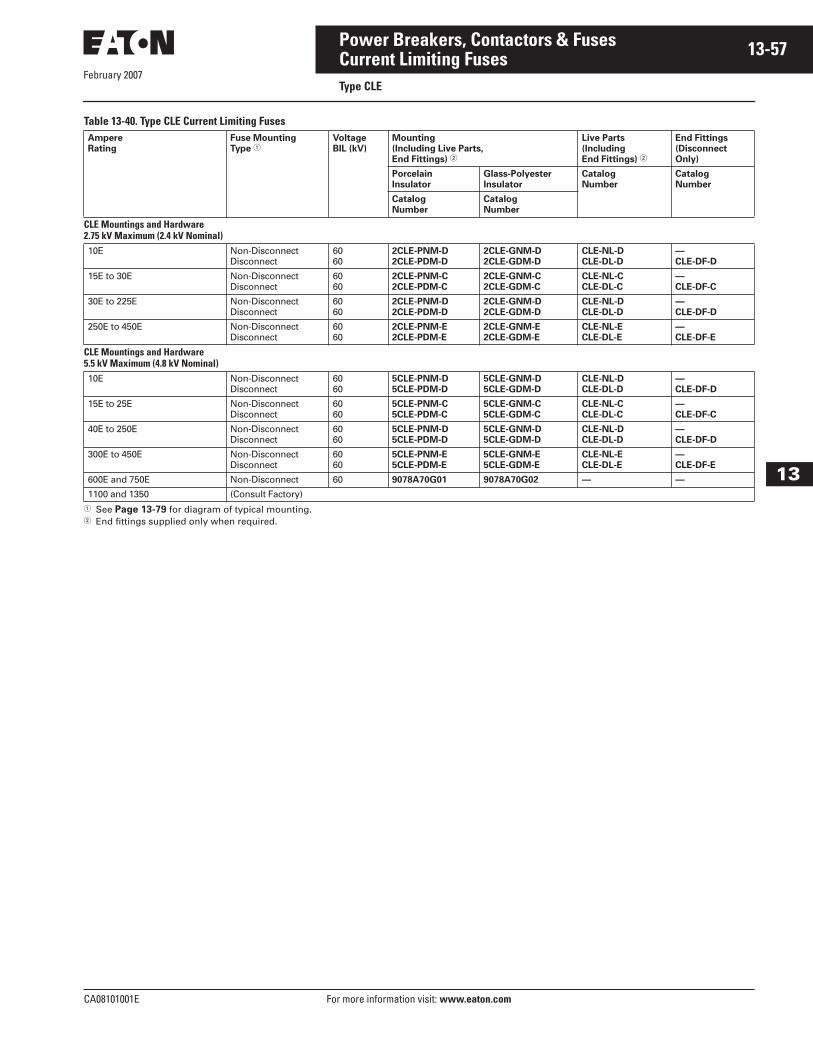
February 2007
CA08101001E For more information visit: www.eaton.com
13-57Power Breakers, Contactors & Fuses
13
Current Limiting FusesType CLE
Table 13-40. Type CLE Current Limiting Fuses
� See Page 13-79 for diagram of typical mounting.� End fittings supplied only when required.
Ampere
Rating
Fuse Mounting
Type �Voltage
BIL (kV)
Mounting
(Including Live Parts,
End Fittings) �
Live Parts
(Including
End Fittings) �
End Fittings
(Disconnect
Only)
Porcelain
Insulator
Glass-Polyester
Insulator
Catalog
Number
Catalog
Number
Catalog
Number
Catalog
Number
CLE Mountings and Hardware2.75 kV Maximum (2.4 kV Nominal)10E Non-Disconnect
Disconnect6060
2CLE-PNM-D
2CLE-PDM-D
2CLE-GNM-D
2CLE-GDM-D
CLE-NL-D
CLE-DL-D
—
CLE-DF-D
15E to 30E Non-DisconnectDisconnect
6060
2CLE-PNM-C
2CLE-PDM-C
2CLE-GNM-C
2CLE-GDM-C
CLE-NL-C
CLE-DL-C
—
CLE-DF-C
30E to 225E Non-DisconnectDisconnect
6060
2CLE-PNM-D
2CLE-PDM-D
2CLE-GNM-D
2CLE-GDM-D
CLE-NL-D
CLE-DL-D
—
CLE-DF-D
250E to 450E Non-DisconnectDisconnect
6060
2CLE-PNM-E
2CLE-PDM-E
2CLE-GNM-E
2CLE-GDM-E
CLE-NL-E
CLE-DL-E
—
CLE-DF-E
CLE Mountings and Hardware5.5 kV Maximum (4.8 kV Nominal)10E Non-Disconnect
Disconnect6060
5CLE-PNM-D
5CLE-PDM-D
5CLE-GNM-D
5CLE-GDM-D
CLE-NL-D
CLE-DL-D
—
CLE-DF-D
15E to 25E Non-DisconnectDisconnect
6060
5CLE-PNM-C
5CLE-PDM-C
5CLE-GNM-C
5CLE-GDM-C
CLE-NL-C
CLE-DL-C
—
CLE-DF-C
40E to 250E Non-DisconnectDisconnect
6060
5CLE-PNM-D
5CLE-PDM-D
5CLE-GNM-D
5CLE-GDM-D
CLE-NL-D
CLE-DL-D
—
CLE-DF-D
300E to 450E Non-DisconnectDisconnect
6060
5CLE-PNM-E
5CLE-PDM-E
5CLE-GNM-E
5CLE-GDM-E
CLE-NL-E
CLE-DL-E
—
CLE-DF-E
600E and 750E Non-Disconnect 60 9078A70G01 9078A70G02 — —
1100 and 1350 (Consult Factory)
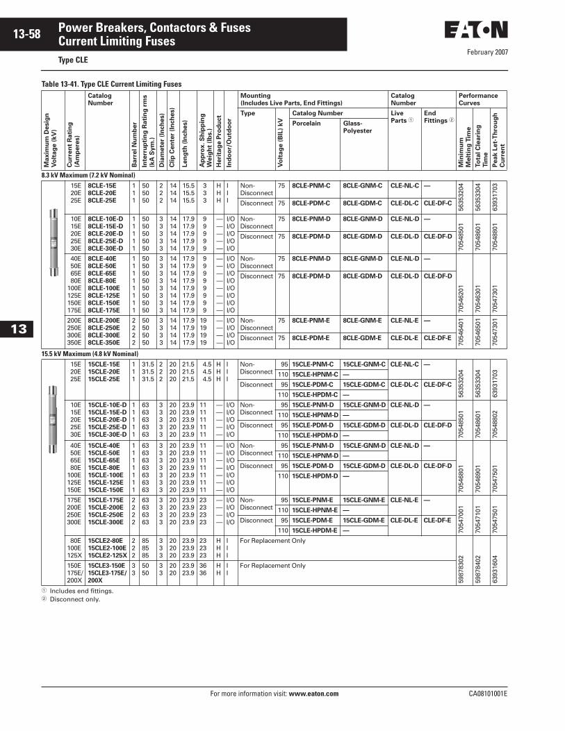
February 2007
13-58
For more information visit: www.eaton.com CA08101001E
Power Breakers, Contactors & Fuses
13
Current Limiting FusesType CLE
Table 13-41. Type CLE Current Limiting Fuses
� Includes end fittings.� Disconnect only.
Ma
xim
um
De
sig
n
Vo
lta
ge
(k
V)
Cu
rre
nt
Ra
tin
g
(Am
pe
res)
Catalog
Number
Ba
rre
l N
um
be
r
Inte
rru
pti
ng
Ra
tin
g r
ms
(kA
Sy
m.)
Dia
me
ter
(In
ch
es)
Clip
Ce
nte
r (I
nch
es)
Le
ng
th (
Inch
es)
Ap
pro
x. S
hip
pin
g
We
igh
t (l
bs.)
He
rita
ge
Pro
du
ct
Ind
oo
r/O
utd
oo
r
Mounting
(Includes Live Parts, End Fittings)
Catalog
Number
Performance
Curves
Type
Vo
lta
ge
(B
IL)
kV
Catalog Number Live
Parts �End
Fittings �
Min
imu
m
Me
ltin
g T
ime
To
tal C
lea
rin
g
Tim
e
Pe
ak
Le
t-T
hro
ug
h
Cu
rre
nt
Porcelain Glass-
Polyester
8.3 kV Maximum (7.2 kV Nominal) 15E 20E 25E
8CLE-15E
8CLE-20E
8CLE-25E
111
505050
222
141414
15.515.515.5
3 3 3
HHH
III
Non-Disconnect
75 8CLE-PNM-C 8CLE-GNM-C CLE-NL-C —
5635
3204
5635
3304
6393
1703
Disconnect 75 8CLE-PDM-C 8CLE-GDM-C CLE-DL-C CLE-DF-C
10E 15E 20E 25E 30E
8CLE-10E-D
8CLE-15E-D
8CLE-20E-D
8CLE-25E-D
8CLE-30E-D
11111
5050505050
33333
1414141414
17.917.917.917.917.9
9 9 9 9 9
—————
I/OI/OI/OI/OI/O
Non-Disconnect
75 8CLE-PNM-D 8CLE-GNM-D CLE-NL-D —
7054
8501
7054
8601
7054
8801
Disconnect 75 8CLE-PDM-D 8CLE-GDM-D CLE-DL-D CLE-DF-D
40E 50E 65E 80E100E125E150E175E
8CLE-40E
8CLE-50E
8CLE-65E
8CLE-80E
8CLE-100E
8CLE-125E
8CLE-150E
8CLE-175E
11111111
5050505050505050
33333333
1414141414141414
17.917.917.917.917.917.917.917.9
9 9 9 9 9 9 9 9
————————
I/OI/OI/OI/OI/OI/OI/OI/O
Non-Disconnect
75 8CLE-PNM-D 8CLE-GNM-D CLE-NL-D —
7054
6201
7054
6301
7054
7301
Disconnect 75 8CLE-PDM-D 8CLE-GDM-D CLE-DL-D CLE-DF-D
200E250E300E350E
8CLE-200E
8CLE-250E
8CLE-300E
8CLE-350E
2222
50505050
3333
14141414
17.917.917.917.9
19191919
————
I/OI/OI/OI/O
Non-Disconnect
75 8CLE-PNM-E 8CLE-GNM-E CLE-NL-E —
7054
6401
7054
6501
7054
7301
Disconnect 75 8CLE-PDM-E 8CLE-GDM-E CLE-DL-E CLE-DF-E
15.5 kV Maximum (4.8 kV Nominal) 15E 20E 25E
15CLE-15E
15CLE-20E
15CLE-25E
111
31.531.531.5
222
202020
21.521.521.5
4.5 4.5 4.5
HHH
III
Non-Disconnect
95 15CLE-PNM-C 15CLE-GNM-C CLE-NL-C —
5635
3204
5635
3304
6393
1703110 15CLE-HPNM-C —
Disconnect 95 15CLE-PDM-C 15CLE-GDM-C CLE-DL-C CLE-DF-C
110 15CLE-HPDM-C —
10E 15E 20E 25E 30E
15CLE-10E-D
15CLE-15E-D
15CLE-20E-D
15CLE-25E-D
15CLE-30E-D
11111
6363636363
33333
2020202020
23.923.923.923.923.9
1111111111
—————
I/OI/OI/OI/OI/O
Non-Disconnect
95 15CLE-PNM-D 15CLE-GNM-D CLE-NL-D —
7054
8501
7054
8601
7054
8802110 15CLE-HPNM-D —
Disconnect 95 15CLE-PDM-D 15CLE-GDM-D CLE-DL-D CLE-DF-D
110 15CLE-HPDM-D —
40E 50E 65E 80E100E125E150E
15CLE-40E
15CLE-50E
15CLE-65E
15CLE-80E
15CLE-100E
15CLE-125E
15CLE-150E
1111111
63636363636363
3333333
20202020202020
23.923.923.923.923.923.923.9
11111111111111
———————
I/OI/OI/OI/OI/OI/OI/O
Non-Disconnect
95 15CLE-PNM-D 15CLE-GNM-D CLE-NL-D —
7054
6801
7054
6901
7054
7501
110 15CLE-HPNM-D —
Disconnect 95 15CLE-PDM-D 15CLE-GDM-D CLE-DL-D CLE-DF-D
110 15CLE-HPDM-D —
175E200E250E300E
15CLE-175E
15CLE-200E
15CLE-250E
15CLE-300E
2222
63636363
3333
20202020
23.923.923.923.9
23232323
————
I/OI/OI/OI/O
Non-Disconnect
95 15CLE-PNM-E 15CLE-GNM-E CLE-NL-E —
7054
7001
7054
7101
7054
7501110 15CLE-HPNM-E —
Disconnect 95 15CLE-PDM-E 15CLE-GDM-E CLE-DL-E CLE-DF-E
110 15CLE-HPDM-E —
80E100E125X
15CLE2-80E
15CLE2-100E
15CLE2-125X
222
858585
333
202020
23.923.923.9
232323
HHH
III
For Replacement Only
5987
8302
5987
8402
6393
1604
150E175E/200X
15CLE3-150E
15CLE3-175E/
200X
33
5050
33
2020
23.923.9
3636
HH
II
For Replacement Only
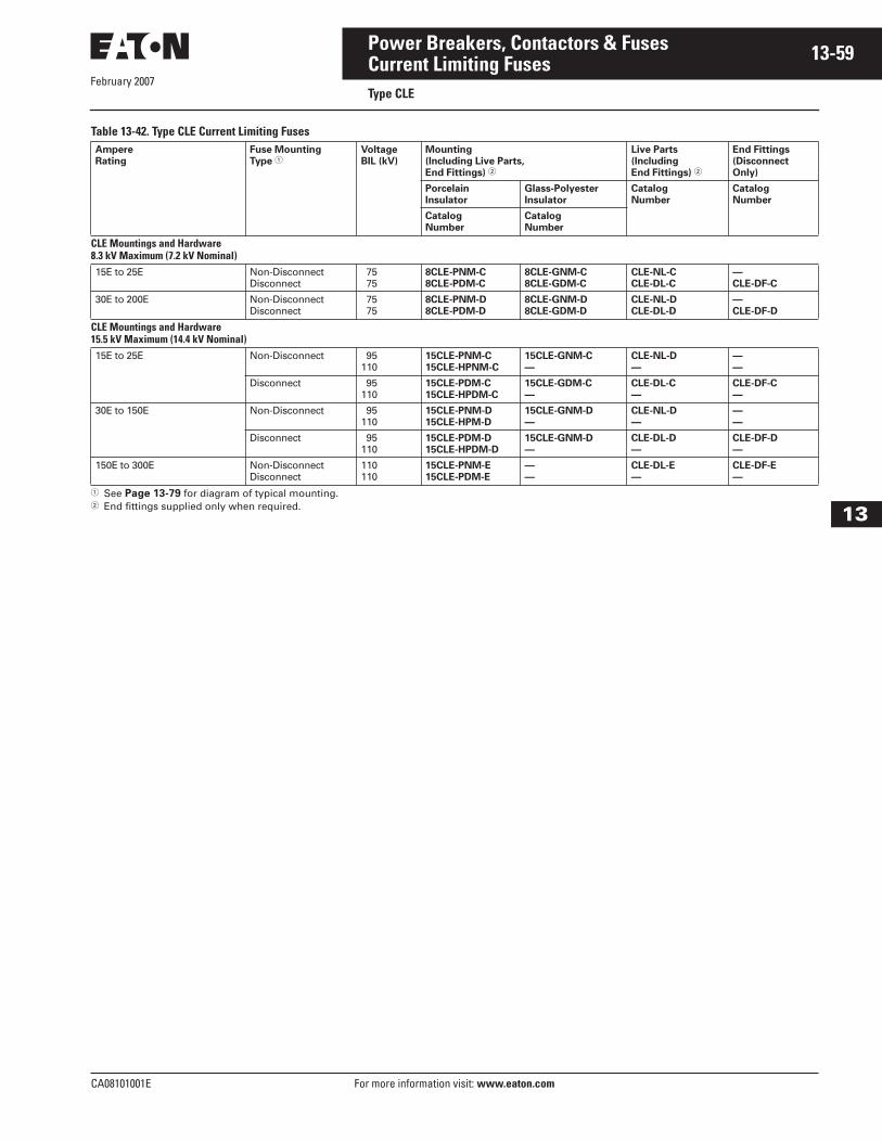
February 2007
CA08101001E For more information visit: www.eaton.com
13-59Power Breakers, Contactors & Fuses
13
Current Limiting FusesType CLE
Table 13-42. Type CLE Current Limiting Fuses
� See Page 13-79 for diagram of typical mounting.� End fittings supplied only when required.
Ampere
Rating
Fuse Mounting
Type �Voltage
BIL (kV)
Mounting
(Including Live Parts,
End Fittings) �
Live Parts
(Including
End Fittings) �
End Fittings
(Disconnect
Only)
Porcelain
Insulator
Glass-Polyester
Insulator
Catalog
Number
Catalog
Number
Catalog
Number
Catalog
Number
CLE Mountings and Hardware8.3 kV Maximum (7.2 kV Nominal)15E to 25E Non-Disconnect
Disconnect 75 75
8CLE-PNM-C
8CLE-PDM-C
8CLE-GNM-C
8CLE-GDM-C
CLE-NL-C
CLE-DL-C
—
CLE-DF-C
30E to 200E Non-DisconnectDisconnect
75 75
8CLE-PNM-D
8CLE-PDM-D
8CLE-GNM-D
8CLE-GDM-D
CLE-NL-D
CLE-DL-D
—
CLE-DF-D
CLE Mountings and Hardware15.5 kV Maximum (14.4 kV Nominal)15E to 25E Non-Disconnect 95
11015CLE-PNM-C
15CLE-HPNM-C
15CLE-GNM-C
—
CLE-NL-D
—
—
—
Disconnect 95110
15CLE-PDM-C
15CLE-HPDM-C
15CLE-GDM-C
—
CLE-DL-C
—
CLE-DF-C
—
30E to 150E Non-Disconnect 95110
15CLE-PNM-D
15CLE-HPM-D
15CLE-GNM-D
—
CLE-NL-D
—
—
—
Disconnect 95110
15CLE-PDM-D
15CLE-HPDM-D
15CLE-GNM-D
—
CLE-DL-D
—
CLE-DF-D
—
150E to 300E Non-DisconnectDisconnect
110110
15CLE-PNM-E
15CLE-PDM-E
—
—
CLE-DL-E
—
CLE-DF-E
—

February 2007
13-60
For more information visit: www.eaton.com CA08101001E
Power Breakers, Contactors & Fuses
13
Current Limiting FusesType HLE
Table 13-43. Type HLE Current Limiting Fuses
� Includes end fittings.� Disconnect only.
Table 13-44. Type HLE Current Limiting Fuses
� See Page 13-79 for diagram of typical mounting.� End fittings supplied only when required.
Ma
xim
um
De
sig
n
Vo
lta
ge
(k
V)
Cu
rre
nt
Ra
tin
g
(Am
pe
res)
Catalog
Number
Ba
rre
l N
um
be
r
Inte
rru
pti
ng
Ra
tin
g r
ms
(kA
Sy
m.)
Dia
me
ter
(In
ch
es)
Clip
Ce
nte
r (I
nch
es)
Le
ng
th (
Inch
es)
Ap
pro
x. S
hip
pin
g
We
igh
t (l
bs.)
He
rita
ge
Pro
du
ct
Ind
oo
r/O
utd
oo
r
Mounting
(Includes Live Parts, End Fittings)
Catalog
Number
Performance
Curves
Type
Vo
ltag
e (
BIL
) kV
Catalog Number Live
Parts �End
Fittings �
Min
imu
m
Me
ltin
g T
ime
To
tal C
lea
rin
g
Tim
e
Pe
ak
Le
t-T
hro
ug
h
Cu
rre
nt
Porcelain Glass-
Polyester
5.5 kV Maximum (4.8 kV Nominal) 10E 15E 20E 25E 30E
5HLE-10E
5HLE-15E
5HLE-20E
5HLE-25E
5HLE-30E
11111
6363636363
33333
1212121212
15.915.915.915.915.9
8 8 8 8 8
—————
I/OI/OI/OI/OI/O
Non-Disconnect
60 5HLE-PNM-D 5HLE-GNM-D CLE-NL-D —
7054
8507
7054
8607
7054
8703
Disconnect 60 5HLE-PDM-D 5HLE-GDM-D CLE-DL-D CLE-DF-D
40E 50E 65E 80E100E125E150E175E200E250E
5HLE-40E
5HLE-50E
5HLE-65E
5HLE-80E
5HLE-100E
5HLE-125E
5HLE-150E
5HLE-175E
5HLE-200E
5HLE-250E
1111111111
63636363636363636363
3333333333
12121212121212121212
15.915.915.915.915.915.915.915.915.915.9
8 8 8 8 8 8 8 8 8 8
——————————
I/OI/OI/OI/OI/OI/OI/OI/OI/OI/O
Non-Disconnect
60 5HLE-PNM-D 5HLE-GNM-D CLE-NL-D —
7054
5805
7054
5905
7054
7603
Disconnect 60 5HLE-PDM-D 5HLE-GDM-D CLE-DL-D CLE-DF-D
300E350E400E450E
5HLE-300E
5HLE-350E
5HLE-400E
5HLE-450E
2222
63636363
3333
12121212
15.915.915.915.9
17171717
————
I/OI/OI/OI/O
Non-Disconnect
60 5HLE-PNM-E 5HLE-GNM-E CLE-NL-E —
7054
6005
7054
6105
7054
7603
Disconnect 60 5HLE-PDM-E 5HLE-GDM-E CLE-DL-E CLE-DF-E
Ampere
Rating
Fuse Mounting
Type �Voltage
BIL (kV)
Mounting
(Including Live Parts,
End Fittings) �
Live Parts
(Including
End Fittings) �
End Fittings
(Disconnect
Only)
Porcelain
Insulator
Glass-Polyester
Insulator
Catalog
Number
Catalog
Number
Catalog
Number
Catalog
Number
SCLE Mountings and Hardware5.5 kV Maximum (4.8 kV Nominal)30E to 225E Non-Disconnect
Non-Disconnect6060
5HLE-PNM-D
5HLE-PDM-D
5HLE-GNM-D
5HLE-GDM-D
CLE-NL-D
CLE-DL-D
—
CLE-DF-D
250E to 400X Non-DisconnectDisconnect
6060
5HLE-PNM-E
5HLE-PDM-E
5HLE-GNM-E
5HLE-GDM-E
CLE-NL-E
CLE-DL-E
—
CLE-DF-E
HLE Mountings and Hardware5.5 kV Maximum (4.8 kV Nominal)30E to 450E Non-Disconnect
Disconnect6060
5HLE-PNM-D
5HLE-PDM-D
5HLE-GNM-D
5HLE-GDM-D
CLE-NL-D
CLE-DL-D
—
CLE-DF-D
300E to 450E Non-DisconnectDisconnect
6060
5HLE-PNM-E
5HLE-PDM-E
5HLE-GNM-E
5HLE-GDM-E
CLE-NL-E
CLE-DL-E
—
CLE-DF-D
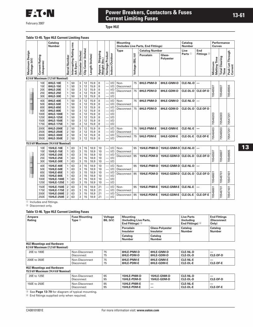
February 2007
CA08101001E For more information visit: www.eaton.com
13-61Power Breakers, Contactors & Fuses
13
Current Limiting FusesType HLE
Table 13-45. Type HLE Current Limiting Fuses
� Includes end fittings.� Disconnect only.
Table 13-46. Type HLE Current Limiting Fuses
� See Page 13-79 for diagram of typical mounting.� End fittings supplied only when required.
Ma
xim
um
De
sig
n
Vo
lta
ge
(k
V)
Cu
rre
nt
Ra
tin
g
(Am
pe
res)
Catalog
Number
Ba
rre
l N
um
be
r
Inte
rru
pti
ng
Ra
tin
g r
ms
(kA
Sy
m.)
Dia
me
ter
(In
ch
es)
Clip
Ce
nte
r (I
nch
es)
Le
ng
th (
Inch
es)
Ap
pro
x. S
hip
pin
g
We
igh
t (l
bs.)
He
rita
ge
Pro
du
ct
Ind
oo
r/O
utd
oo
r
Mounting
(Includes Live Parts, End Fittings)
Catalog
Number
Performance
Curves
Type
Vo
ltag
e (
BIL
) kV
Catalog Number Live
Parts �End
Fittings �
Min
imu
m
Me
ltin
g T
ime
To
tal C
lea
rin
g
Tim
e
Pe
ak
Le
t-T
hro
ug
h
Cu
rre
nt
Porcelain Glass-
Polyester
8.3 kV Maximum (7.2 kV Nominal) 10E 15E 20E 25E 30E
8HLE-10E
8HLE-15E
8HLE-20E
8HLE-25E
8HLE-30E
11111
5050505050
33333
1212121212
15.915.915.915.915.9
88888
—————
I/OI/OI/OI/OI/O
Non-Disconnect
75 8HLE-PNM-D 8HLE-GNM-D CLE-NL-D —
7054
8507
7054
8607
7054
8804
Disconnect 75 8HLE-PDM-D 8HLE-GDM-D CLE-DL-D CLE-DF-D
40E 50E 65E 80E100E125E150E175E
8HLE-40E
8HLE-50E
8HLE-65E
8HLE-80E
8HLE-100E
8HLE-125E
8HLE-150E
8HLE-175E
11111111
5050505050505050
33333333
1212121212121212
15.915.915.915.915.915.915.915.9
88888888
————————
I/OI/OI/OI/OI/OI/OI/OI/O
Non-Disconnect
75 8HLE-PNM-D 8HLE-GNM-D CLE-NL-D —
7054
6203
7054
6303
7054
7201
Disconnect 75 8HLE-PDM-D 8HLE-GDM-D CLE-DL-D CLE-DF-D
200E250E300E350E
8HLE-200E
8HLE-250E
8HLE-300E
8HLE-350E
2222
50505050
3333
12121212
15.915.915.915.9
8888
————
I/OI/OI/OI/O
Non-Disconnect
75 5HLE-PNM-E 5HLE-GNM-E CLE-NL-E —
7054
6403
7054
6503
7054
7201
Disconnect 75 5HLE-PDM-E 5HLE-GDM-E CLE-DL-E CLE-DF-E
15.5 kV Maximum (14.4 kV Nominal) 10E 15E 20E 25E 30E
15HLE-10E
15HLE-15E
15HLE-20E
15HLE-25E
15HLE-30E
11111
6363636363
33333
1515151515
18.918.918.918.918.9
1010101010
—————
I/OI/OI/OI/OI/O
Non-Disconnect
95 15HLE-PNM-D 15HLE-GNM-D CLE-NL-D —
7054
8507
7054
8607
7054
8805
Disconnect 95 15HLE-PDM-D 15HLE-GDM-D CLE-DL-D CLE-DF-D
40E 50E 65E 80E100E125E
15HLE-40E
15HLE-50E
15HLE-65E
15HLE-80E
15HLE-100E
15HLE-125E
111111
636363636363
333333
151515151515
18.918.918.918.918.918.9
101010101010
——————
I/OI/OI/OI/OI/OI/O
Non-Disconnect
95 15HLE-PNM-D 15HLE-GNM-D CLE-NL-D —
7054
6601
7054
6701
7054
7401Disconnect 95 15HLE-PDM-D 15HLE-GDM-D CLE-DL-D CLE-DF-D
150E175E200E250E
15HLE-150E
15HLE-175E
15HLE-200E
15HLE-250E
2222
63636363
3333
15151515
18.918.918.918.9
21212121
————
I/OI/OI/OI/O
Non-Disconnect
95 15HLE-PNM-E 15HLE-GNM-E CLE-NL-E —
7054
6601
7054
6701
7054
7401
Disconnect 95 15HLE-PDM-E 15HLE-GDM-E CLE-DL-E CLE-DF-E
Ampere
Rating
Fuse Mounting
Type �Voltage
BIL (kV)
Mounting
(Including Live Parts,
End Fittings) �
Live Parts
(Including
End Fittings) �
End Fittings
(Disconnect
Only)
Porcelain
Insulator
Glass-Polyester
Insulator
Catalog
Number
Catalog
Number
Catalog
Number
Catalog
Number
HLE Mountings and Hardware8.3 kV Maximum (7.2 kV Nominal) 20E to 180E Non-Disconnect
Disconnect7575
8HLE-PNM-D
8HLE-PDM-D
8HLE-GNM-D
8HLE-GDM-D
CLE-NL-D
CLE-DL-D
—
CLE-DF-D
200E to 350E Non-DisconnectDisconnect
7575
8HLE-PNM-E
8HLE-PDM-E
8HLE-GNM-E
8HLE-GDM-E
CLE-NL-E
CLE-DL-E
—
CLE-DF-E
HLE Mountings and Hardware15.5 kV Maximum (14.4 kV Nominal) 20E to 125E Non-Disconnect
Disconnect9595
15HLE-PNM-D
15HLE-PDM-D
15HLE-GNM-D
15HLE-GDM-D
CLE-NL-D
CLE-DL-D
—
CLE-DF-D
150E to 250E Non-DisconnectDisconnect
9595
15HLE-PNM-E
15HLE-PDM-E
—
—
CLE-NL-E
CLE-DL-E
—
CLE-DF-E

February 2007
13-62
For more information visit: www.eaton.com CA08101001E
Power Breakers, Contactors & Fuses
13
Current Limiting FusesType BHLE
Table 13-47. Type BHLE Current Limiting Fuses (5.5 kV Maximum, 4.8 kV Nominal)
� Includes end fittings.� Disconnect only.� Bolt-in.
Table 13-48. Type BHLE Current Limiting Fuses (8.3 kV Maximum, 7.2 kV Nominal)
� Includes end fittings.� Disconnect only.� Bolt-in.
Maxim
um
Desig
n
Vo
ltag
e (
kV
)
Cu
rren
t R
ati
ng
(Am
pere
s)
Catalog
Number
Barr
el N
um
ber
Inte
rru
pti
ng
Rati
ng
rm
s
(kA
Sym
.)
Dia
mete
r (I
nch
es)
Clip
Cen
ter
(In
ch
es)
Len
gth
(In
ch
es)
Ap
pro
x. S
hip
pin
g
Weig
ht
(Lb
s.)
Heri
tag
e P
rod
uct
Ind
oo
r/O
utd
oo
r
Mounting
(Includes Live Parts,
End Fittings)
Catalog
Number
Performance
Curves
Type
Vo
ltag
e (
BIL
) kV
Catalog Number Live
Parts �End
Fittings �
Min
imu
m
Melt
ing
Tim
e
To
tal C
leari
ng
Tim
e
Peak L
et-
Th
rou
gh
Cu
rren
t
Porcelain Glass-
Polyester
5.5 10E 15E 20E 25E 30E
5BHLE-10E
5BHLE-15E
5BHLE-20E
5BHLE-25E
5BHLE-30E
11111
6363636363
33333
�
�
�
�
�
15.915.915.915.915.9
88888
—————
IIIII
Non-Disconnect
Bolt-on. Not applicable.
7054
8507
7054
8607
7054
8703
Disconnect
40E 50E 65E 80E100E125E150E175E200E250E
5BHLE-40E
5BHLE-50E
5BHLE-65E
5BHLE-80E
5BHLE-100E
5BHLE-125E
5BHLE-150E
5BHLE-175E
5BHLE-200E
5BHLE-250E
1111111111
63636363636363636363
3333333333
�
�
�
�
�
�
�
�
�
�
15.915.915.915.915.915.915.915.915.915.9
8888888888
——————————
IIIIIIIIII
Non-Disconnect
7054
5805
7054
5905
7054
7603
Disconnect
300E350E400E450E
5BHLE-300E
5BHLE-350E
5BHLE-400E
5BHLE-450E
1111
63636363
3333
�
�
�
�
15.915.915.915.9
8888
————
IIII
Non-Disconnect
7054
6005
7054
6105
7054
7603
Disconnect
Maxim
um
Desig
n
Vo
ltag
e (
kV
)
Cu
rren
t R
ati
ng
(Am
pere
s)
Catalog
Number
Barr
el N
um
ber
Inte
rru
pti
ng
Rati
ng
rm
s
(kA
Sym
.)
Dia
mete
r (I
nch
es)
Clip
Cen
ter
(In
ch
es)
Len
gth
(In
ch
es)
Ap
pro
x. S
hip
pin
g
Weig
ht
(Lb
s.)
Heri
tag
e P
rod
uct
Ind
oo
r/O
utd
oo
r
Mounting
(Includes Live Parts,
End Fittings)
Catalog
Number
Performance
Curves
Type
Vo
ltag
e (
BIL
) kV
Catalog Number Live
Parts �End
Fittings �
Min
imu
m
Melt
ing
Tim
e
To
tal C
leari
ng
Tim
e
Peak L
et-
Th
rou
gh
Cu
rren
t
Porcelain Glass-
Polyester
8.3 10E 15E 20E 25E 30E
8BHLE-10E
8BHLE-15E
8BHLE-20E
8BHLE-25E
8BHLE-30E
11111
5050505050
33333
�
�
�
�
�
15.915.915.915.915.9
8 8 8 8 8
—————
IIIII
Bolt-on. Not applicable.70
5485
07
7054
8607
7054
8804
40E 50E 65E 80E100E125E150E175E
8BHLE-40E
8BHLE-50E
8BHLE-65E
8BHLE-80E
8BHLE-100E
8BHLE-125E
8BHLE-150E
8BHLE-175E
11111111
5050505050505050
33333333
�
�
�
�
�
�
�
�
15.915.915.915.915.915.915.915.9
8 8 8 8 8 8 8 8
————————
IIIIIIII 70
5462
03
7054
6303
7054
7201
200E250E300E350E
8BHLE-200E
8BHLE-250E
8BHLE-300E
8BHLE-350E
1111
50505050
3333
�
�
�
�
15.915.915.915.9
17171717
————
IIII 70
5464
03
7054
6503
7054
7201
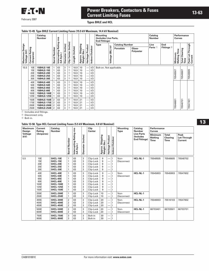
February 2007
CA08101001E For more information visit: www.eaton.com
13-63Power Breakers, Contactors & Fuses
13
Current Limiting FusesTypes BHLE and HCL
Table 13-49. Type BHLE Current Limiting Fuses (15.5 kV Maximum, 14.4 kV Nominal)
� Includes end fittings.� Disconnect only.� Bolt-in.
Table 13-50. Type HCL Current Limiting Fuses (5.5 kV Maximum, 4.8 kV Nominal)
Maxim
um
Desig
n
Vo
ltag
e (
kV
)
Cu
rren
t R
ati
ng
(Am
pere
s)
Catalog
Number
Barr
el N
um
ber
Inte
rru
pti
ng
Rati
ng
rm
s
(kA
Sym
.)
Dia
mete
r (I
nch
es)
Clip
Cen
ter
(In
ch
es)
Len
gth
(In
ch
es)
Ap
pro
x. S
hip
pin
g
Weig
ht
(lb
s.)
Heri
tag
e P
rod
uct
Ind
oo
r/O
utd
oo
r
Mounting
(Includes Live Parts,
End Fittings)
Catalog
Number
Performance
Curves
Type
Vo
ltag
e (
BIL
) kV
Catalog Number Live
Parts �End
Fittings �
Min
imu
m
Melt
ing
Tim
e
To
tal C
leari
ng
Tim
e
Peak L
et-
Th
rou
gh
Cu
rren
t
Porcelain Glass-
Polyester
15.5 10E 15E 20E 25E 30E
15BHLE-10E
15BHLE-15E
15BHLE-20E
15BHLE-25E
15BHLE-30E
11111
6363636363
33333
�
�
�
�
�
18.918.918.918.918.9
1010101010
—————
I/OI/OI/OI/OI/O
Bolt-on. Not applicable.
7054
8507
7054
8607
7054
8805
40E 50E 65E 80E100E125E
15BHLE-40E
15BHLE-50E
15BHLE-65E
15BHLE-80E
15BHLE-100E
15BHLE-125E
111111
636363636363
333333
�
�
�
�
�
�
18.918.918.918.918.918.9
101010101010
——————
I/OI/OI/OI/OI/OI/O
7054
6601
7054
6701
7054
7401150E
175E200E250E
15BHLE-150E
15BHLE-175E
15BHLE-200E
15BHLE-250E
2222
63636363
3333
�
�
�
�
18.918.918.918.9
21212121
————
I/OI/OI/OI/O
Maximum
Design
Voltage
(kV)
Current
Rating
(Amperes)
Catalog
Number
Barr
el N
um
ber
Inte
rru
pti
ng
Rati
ng
rm
s
(kA
Sym
.)
Dia
mete
r (I
nch
es)
Clip
Center
Ap
pro
x. S
hip
pin
g
Weig
ht
(lb
s.)
Heri
tag
e P
rod
uct
Ind
oo
r/O
utd
oo
r
Mounting
Type
Catalog
Number
Live Parts
(Includes
End Fittings)
Performance
Curves
Minimum
Melting
Time
Total
Clearing
Time
Peak
Let-Through
Current
5.5 10E 15E 20E 25E 30E
5HCL-10E
5HCL-15E
5HCL-20E
5HCL-25E
5HCL-30E
11111
6363636363
33333
Clip-LockClip-LockClip-LockClip-LockClip-Lock
9 9 9 9 9
—————
IIIII
Non-Disconnect
HCL-NL-1 70548505 70548605 70548702
40E 50E 65E 80E100E125E150E
5HCL-40E
5HCL-50E
5HCL-65E
5HCL-80E
5HCL-100E
5HCL-125E
5HCL-150E
1111111
63636363636363
3333333
Clip-LockClip-LockClip-LockClip-LockClip-LockClip-LockClip-Lock
9 9 9 9 9 9 9
———————
IIIIIII
Non-Disconnect
HCL-NL-1 70545803 70545903 70547602
200E250E
5HCL-200E
5HCL-250E
11
6363
33
Clip-LockClip-Lock
1010
——
II
Non-Disconnect
HCL-NL-1
300E400E450E
5HCL-300E
5HCL-400E
5HCL-450E
222
636363
333
Clip-LockClip-LockClip-Lock
202020
———
III
Non-Disconnect
HCL-NL-1 70546003 70516103 70547602
500E600E
5HCL-500E
5HCL-600E
22
6363
33
Clip-LockClip-Lock
2020
——
II
Non-Disconnect
HCL-NL-1 66703401 66703501 66703701
750E900E
5HCL-750E
5HCL-900E
33
6363
33
Bolt-inBolt-in
3030
——
II

February 2007
13-64
For more information visit: www.eaton.com CA08101001E
Power Breakers, Contactors & Fuses
13
Current Limiting FusesType HCL
Table 13-51. Type HCL Current Limiting Fuses (15.5 kV Maximum, 14.4 kV Nominal) Maximum
Design
Voltage
(kV)
Current
Rating
(Amperes)
Catalog
Number
Barr
el N
um
ber
Inte
rru
pti
ng
Rati
ng
rm
s
(kA
Sym
.)
Dia
mete
r (I
nch
es)
Clip
Center
Ap
pro
x. S
hip
pin
g
Weig
ht
(lb
s.)
Heri
tag
e P
rod
uct
Ind
oo
r/O
utd
oo
r
Mounting
Type
Catalog
Number
Live Parts
(Includes
End Fittings)
Performance
Curves
Minimum
Melting
Time
Total
Clearing
Time
Peak
Let-Through
Current
15.5 10E 15E 20E 25E 30E
15HCL-10E
15HCL-15E
15HCL-20E
15HCL-25E
15HCL-30E
11111
6363636363
33333
Clip-LockClip-LockClip-LockClip-LockClip-Lock
1010101010
—————
IIIII
Non-Disconnect
HCL-NL-1 70548503 70548603 70548803
40E 50E
15HCL-40E
15HCL-50E
11
6363
33
Clip-LockClip-Lock
1010
——
II
Non-Disconnect
HCL-NL-1 66703201 66703301 70547402
65E 80E100E125E
15HCL-65E
15HCL-80E
15HCL-100E
15HCL-125E
1111
50505050
3333
Clip-LockClip-LockClip-LockClip-Lock
12121212
————
IIII
Non-Disconnect
HCL-NL-1
150E200E250E300E
15HCL-150E
15HCL-200E
15HCL-250E
15HCL-300E
2222
50505050
3333
Clip-LockClip-LockClip-LockClip-Lock
24242424
————
IIII
Non-Disconnect
HCL-NL-1 66703201 66703301 70547402
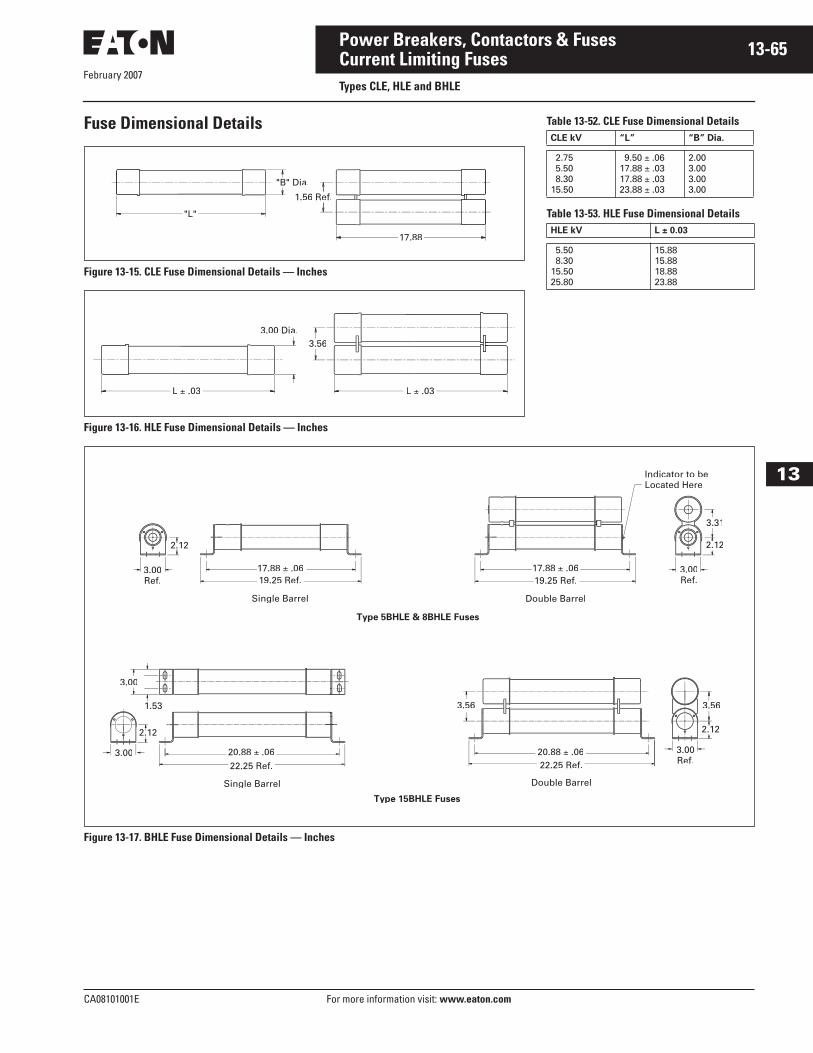
CA08101001E For more information visit: www.eaton.com
13-65Power Breakers, Contactors & Fuses
February 2007
13
Current Limiting FusesTypes CLE, HLE and BHLE
Fuse Dimensional Details
Figure 13-15. CLE Fuse Dimensional Details — Inches
Figure 13-16. HLE Fuse Dimensional Details — Inches
Figure 13-17. BHLE Fuse Dimensional Details — Inches
"L"
17.88
"B" Dia.
1.56 Ref.
3.56
L ± .03 L ± .03
3.00 Dia.
Type 5BHLE & 8BHLE Fuses
3.00
3.00
3.00Ref.
Single Barrel
17.88 ± .0619.25 Ref.
Double Barrel
22.25 Ref.20.88 ± .06
3.56
Indicator to beLocated Here
Double Barrel
19.25 Ref.17.88 ± .06
3.31
2.12
Type 15BHLE Fuses
3.00Ref.
1.53
Single Barrel
20.88 ± .06
22.25 Ref.
3.56
Ref.
Table 13-52. CLE Fuse Dimensional Details
Table 13-53. HLE Fuse Dimensional Details
CLE kV “L” “B” Dia.
2.75 5.50 8.3015.50
9.50 ± .0617.88 ± .0317.88 ± .0323.88 ± .03
2.003.003.003.00
HLE kV L ± 0.03
5.50 8.3015.5025.80
15.8815.8818.8823.88
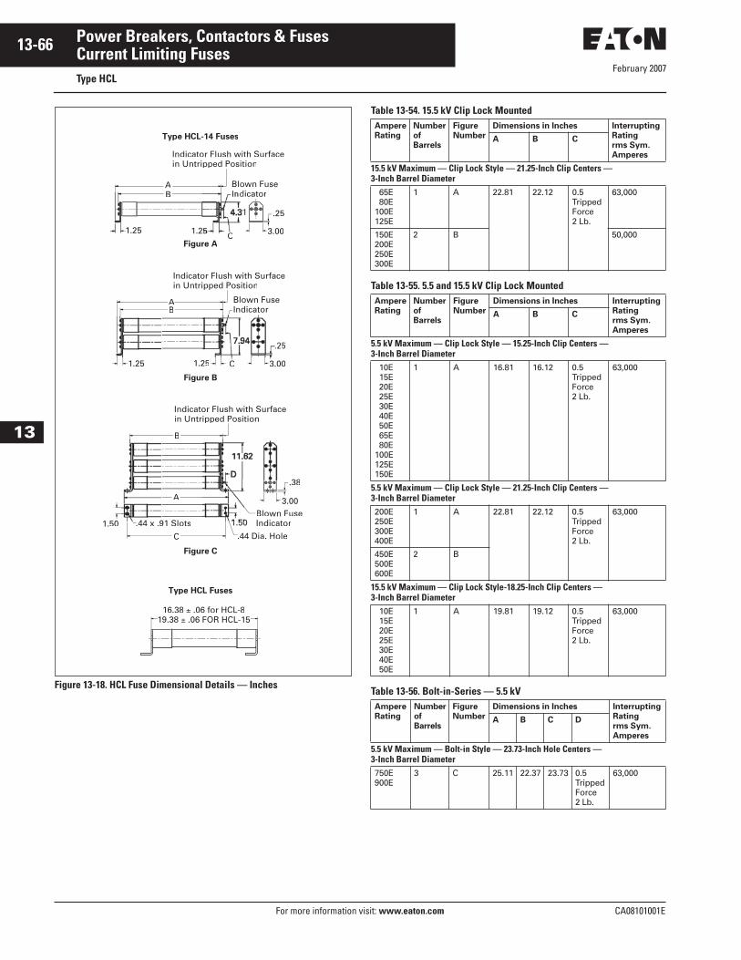
February 2007
13-66
For more information visit: www.eaton.com CA08101001E
Power Breakers, Contactors & Fuses
13
Current Limiting FusesType HCL
Figure 13-18. HCL Fuse Dimensional Details — Inches
Table 13-54. 15.5 kV Clip Lock Mounted
Table 13-55. 5.5 and 15.5 kV Clip Lock Mounted
Table 13-56. Bolt-in-Series — 5.5 kV
16.38 ± .06 for HCL-819.38 ± .06 FOR HCL-15
Type HCL-14 Fuses
Type HCL Fuses
Figure A
BA
3.00
Indicator Flush with Surfacein Untripped Position
Indicator
.25
1.25
Figure B
1.25 1.25 3.00
AAB
5
Indicator Flush with Surfacein Untripped Position
Figure C
1.50 .44 x .91 Slots
C .44 Dia. Hole
A
B
.38
Indicator Flush with Surfacein Untripped Position
Blown FuseIndicator
C
C
Ampere
Rating
Number
of
Barrels
Figure
Number
Dimensions in Inches Interrupting
Rating
rms Sym.
Amperes
A B C
15.5 kV Maximum — Clip Lock Style — 21.25-Inch Clip Centers —3-Inch Barrel Diameter 65E 80E100E125E
1 A 22.81 22.12 0.5TrippedForce2 Lb.
63,000
150E200E250E300E
2 B 50,000
Ampere
Rating
Number
of
Barrels
Figure
Number
Dimensions in Inches Interrupting
Rating
rms Sym.
Amperes
A B C
5.5 kV Maximum — Clip Lock Style — 15.25-Inch Clip Centers —3-Inch Barrel Diameter 10E 15E 20E 25E 30E 40E 50E 65E 80E100E125E150E
1 A 16.81 16.12 0.5TrippedForce2 Lb.
63,000
5.5 kV Maximum — Clip Lock Style — 21.25-Inch Clip Centers —3-Inch Barrel Diameter200E250E300E400E
1 A 22.81 22.12 0.5Tripped Force2 Lb.
63,000
450E500E600E
2 B
15.5 kV Maximum — Clip Lock Style-18.25-Inch Clip Centers —3-Inch Barrel Diameter 10E 15E 20E 25E 30E 40E 50E
1 A 19.81 19.12 0.5Tripped Force2 Lb.
63,000
Ampere
Rating
Number
of
Barrels
Figure
Number
Dimensions in Inches Interrupting
Rating
rms Sym.
Amperes
A B C D
5.5 kV Maximum — Bolt-in Style — 23.73-Inch Hole Centers —3-Inch Barrel Diameter750E900E
3 C 25.11 22.37 23.73 0.5TrippedForce2 Lb.
63,000

February 2007
CA08101001E For more information visit: www.eaton.com
13-67Power Breakers, Contactors & Fuses
13
Current Limiting FusesType CLS
Table 13-57. CLS Type Current Limiting Fuses
� Includes end fittings.� Disconnect only.� Not applicable.
Maxim
um
Desig
n
Vo
ltag
e (
kV
)
Cu
rren
t R
ati
ng
(Am
pere
s)
“R
” D
esig
nati
on
Catalog
Number
Barr
el N
um
ber
Inte
rru
pti
ng
Rati
ng
rm
s
(kA
Sym
.)
Dia
mete
r (I
nch
es)
Clip
Cen
ter
(In
ch
es)
Len
gth
(In
ch
es)
Ap
pro
x. S
hip
pin
g
Weig
ht
(Lb
s.)
Mounting
(Includes Live Parts, End Fittings)
Catalog
Number
Performance
Curves
Type
Vo
ltag
e (
BIL
) kV
Catalog Number Live
Parts �End
Fittings �
Min
imu
m
Melt
ing
Tim
e
To
tal C
leari
ng
Tim
e
Peak L
et-
Th
rou
gh
Cu
rren
t
Porcelain Glass-
Polyester
2.54 25 70100130150170200230
— 2R 3R 4R 5R 6R 9R12R
2CLS-25
2CLS-2R
2CLS-3R
2CLS-4R
2CLS-5R
2CLS-6R
2CLS-9R
2CLS-12R
11111111
5050505050505050
33333333
77777777
10.810.810.810.810.810.810.810.8
7 7 7 7 7 7 7 7
Non-Disconnect
60 2CLE-PNM-D 2CLE-GNM-D CLE-NL-D —
6666
4702
6666
4704
6670
0202
Disconnect 60 2CLE-PDM-D 2CLE-GDM-E CLE-DL-D CLE-DF-D
390450
18R24R
2CLS-18R
2CLS-24R
22
5050
33
77
10.810.8
1616
Non-Disconnect
60 2CLE-PNM-E 2CLE-GNM-E CLE-NL-E —
Disconnect 60 2CLE-PDME 2CLE-GDM-E CLE-DL-E CLE-DF-E
25 70100130150170200230
— 2R 3R 4R 5R 6R 9R12R
2ACLS-25
2ACLS-2R
2ACLS-3R
2ACLS-4R
2ACLS-5R
2ACLS-6R
2ACLS-9R
2ACLS-12R
11111111
5050505050505050
33333333
�
�
�
�
�
�
�
�
10.810.810.810.810.810.810.810.8
7 7 7 7 7 7 7 7
For use with AMPGARD 400 A Motor Starters
6666
4702
6666
4704
6670
0202
390450
18R24R
2ACLS-18R
2ACLS-24R
22
5050
33
�
�10.810.8
1616
25 70100130150170200230
— 2R 3R 4R 5R 6R 9R12R
2BCLS-25
2BCLS-2R
2BCLS-3R
2BCLS-4R
2BCLS-5R
2BCLS-6R
2BCLS-9R
2BCLS-12R
11111111
5050505050505050
33333333
�
�
�
�
�
�
�
�
10.810.810.810.810.810.810.810.8
8 8 8 8 8 8 8 8
Bolt-in
6666
4702
6666
4704
6670
0202
390450
18R24R
2BCLS-18R
2BCLS-24R
22
5050
33
�
�10.810.8
1717
25 70100130150170200230
— 2R 3R 4R 5R 6R 9R12R
2HCLS-25
2HCLS-2R
2HCLS-3R
2HCLS-4R
2HCLS-5R
2HCLS-6R
2HCLS-9R
2HCLS-12R
11111111
5050505050505050
33333333
�
�
�
�
�
�
�
�
10.810.810.810.810.810.810.810.8
7 7 7 7 7 7 7 7
Hermetically Sealed Fuses for use with AMPGARD 400 A Motor Starters
6666
4702
6666
4704
6670
0202
390450
18R24R
2HCLS-18R
2HCLS-24R
22
5050
33
�
�10.810.8
1616
5.5 30 70100130150170200230
— 2R 3R 4R 5R 6R 9R12R
5CLS-30
5CLS-2R
5CLS-3R
5CLS-4R
5CLS-5R
5CLS-6R
5CLS-9R
5CLS-12R
11111111
5050505050505050
33333333
1212121212121212
15.915.915.915.915.915.915.915.9
8 8 8 8 8 8 8 8
Non-Disconnect
60 5HLE-PNM-D 5HLE-GNM-D CLE-NL-D —
6669
0602
6669
0702
6670
0203
Disconnect 60 5HLE-PDM-D 5HLE-GDM-E CLE-DL-D CLE-DF-D
390450
18R24R
5CLS-18R
5CLS-24R
22
5050
33
1212
15.915.9
1717
Non-Disconnect
60 5HLE-PNM-E 5HLE-GNM-E CLE-NL-E —
Disconnect 60 5HLE-PDME 5HLE-GDM-E CLE-DL-E CLE-DF-E
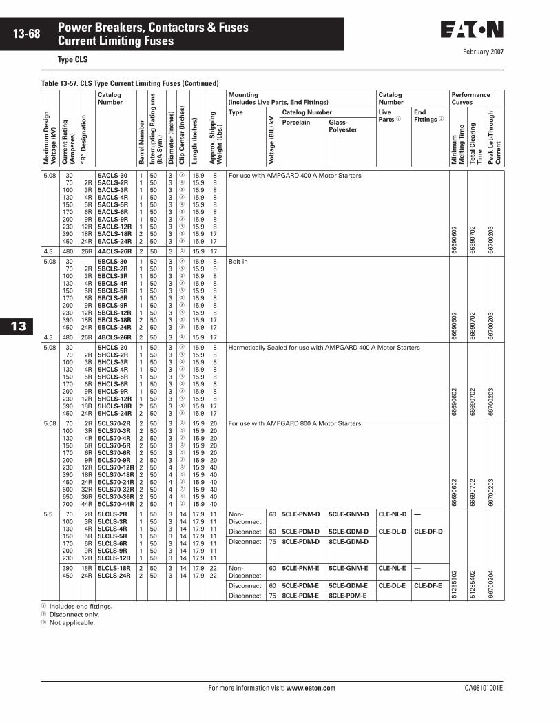
February 2007
13-68
For more information visit: www.eaton.com CA08101001E
Power Breakers, Contactors & Fuses
13
Current Limiting FusesType CLS
Table 13-57. CLS Type Current Limiting Fuses (Continued)
� Includes end fittings.� Disconnect only.� Not applicable.
Maxim
um
Desig
n
Vo
ltag
e (
kV
)
Cu
rren
t R
ati
ng
(Am
pere
s)
“R
” D
esig
nati
on
Catalog
Number
Barr
el N
um
ber
Inte
rru
pti
ng
Rati
ng
rm
s
(kA
Sym
.)
Dia
mete
r (I
nch
es)
Clip
Cen
ter
(In
ch
es)
Len
gth
(In
ch
es)
Ap
pro
x. S
hip
pin
g
Weig
ht
(Lb
s.)
Mounting
(Includes Live Parts, End Fittings)
Catalog
Number
Performance
Curves
Type
Vo
ltag
e (
BIL
) kV
Catalog Number Live
Parts �End
Fittings �
Min
imu
m
Melt
ing
Tim
e
To
tal C
leari
ng
Tim
e
Peak L
et-
Th
rou
gh
Cu
rren
t
Porcelain Glass-
Polyester
5.08 30 70100130150170200230390450
— 2R 3R 4R 5R 6R 9R12R18R24R
5ACLS-30
5ACLS-2R
5ACLS-3R
5ACLS-4R
5ACLS-5R
5ACLS-6R
5ACLS-9R
5ACLS-12R
5ACLS-18R
5ACLS-24R
1111111122
50505050505050505050
3333333333
�
�
�
�
�
�
�
�
�
�
15.915.915.915.915.915.915.915.915.915.9
8 8 8 8 8 8 8 81717
For use with AMPGARD 400 A Motor Starters
6669
0602
6669
0702
6670
0203
4.3 480 26R 4ACLS-26R 2 50 3 � 15.9 17
5.08 30 70100130150170200230390450
— 2R 3R 4R 5R 6R 9R12R18R24R
5BCLS-30
5BCLS-2R
5BCLS-3R
5BCLS-4R
5BCLS-5R
5BCLS-6R
5BCLS-9R
5BCLS-12R
5BCLS-18R
5BCLS-24R
1111111122
50505050505050505050
3333333333
�
�
�
�
�
�
�
�
�
�
15.915.915.915.915.915.915.915.915.915.9
8 8 8 8 8 8 8 81717
Bolt-in
6669
0602
6669
0702
6670
0203
4.3 480 26R 4BCLS-26R 2 50 3 � 15.9 17
5.08 30 70100130150170200230390450
— 2R 3R 4R 5R 6R 9R12R18R24R
5HCLS-30
5HCLS-2R
5HCLS-3R
5HCLS-4R
5HCLS-5R
5HCLS-6R
5HCLS-9R
5HCLS-12R
5HCLS-18R
5HCLS-24R
1111111122
50505050505050505050
3333333333
�
�
�
�
�
�
�
�
�
�
15.915.915.915.915.915.915.915.915.915.9
8 8 8 8 8 8 8 81717
Hermetically Sealed for use with AMPGARD 400 A Motor Starters
6669
0602
6669
0702
6670
0203
5.08 70100130150170200230390450600650700
2R 3R 4R 5R 6R 9R12R18R24R32R36R44R
5CLS70-2R
5CLS70-3R
5CLS70-4R
5CLS70-5R
5CLS70-6R
5CLS70-9R
5CLS70-12R
5CLS70-18R
5CLS70-24R
5CLS70-32R
5CLS70-36R
5CLS70-44R
222222222222
505050505050505050505050
333333444444
�
�
�
�
�
�
�
�
�
�
�
�
15.915.915.915.915.915.915.915.915.915.915.915.9
202020202020404040404040
For use with AMPGARD 800 A Motor Starters
6669
0602
6669
0702
6670
0203
5.5 70100130150170200230
2R 3R 4R 5R 6R 9R12R
5LCLS-2R
5LCLS-3R
5LCLS-4R
5LCLS-5R
5LCLS-6R
5LCLS-9R
5LCLS-12R
1111111
50505050505050
3333333
14141414141414
17.917.917.917.917.917.917.9
11111111111111
Non-Disconnect
60 5CLE-PNM-D 5CLE-GNM-D CLE-NL-D —
5128
5302
5128
5402
6670
0204
Disconnect 60 5CLE-PDM-D 5CLE-GDM-D CLE-DL-D CLE-DF-D
Disconnect 75 8CLE-PDM-D 8CLE-GDM-D
390450
18R24R
5LCLS-18R
5LCLS-24R
22
5050
33
1414
17.917.9
2222
Non-Disconnect
60 5CLE-PNM-E 5CLE-GNM-E CLE-NL-E —
Disconnect 60 5CLE-PDM-E 5CLE-GDM-E CLE-DL-E CLE-DF-E
Disconnect 75 8CLE-PDM-E 8CLE-PDM-E
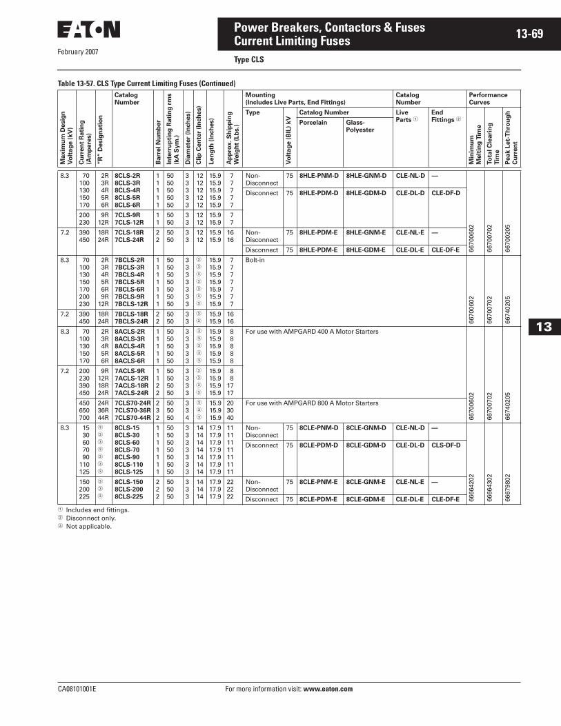
February 2007
CA08101001E For more information visit: www.eaton.com
13-69Power Breakers, Contactors & Fuses
13
Current Limiting FusesType CLS
Table 13-57. CLS Type Current Limiting Fuses (Continued)
� Includes end fittings.� Disconnect only.� Not applicable.
Maxim
um
Desig
n
Vo
ltag
e (
kV
)
Cu
rren
t R
ati
ng
(Am
pere
s)
“R
” D
esig
nati
on
Catalog
Number
Barr
el N
um
ber
Inte
rru
pti
ng
Rati
ng
rm
s
(kA
Sym
.)
Dia
mete
r (I
nch
es)
Clip
Cen
ter
(In
ch
es)
Len
gth
(In
ch
es)
Ap
pro
x. S
hip
pin
g
Weig
ht
(Lb
s.)
Mounting
(Includes Live Parts, End Fittings)
Catalog
Number
Performance
Curves
Type
Vo
ltag
e (
BIL
) kV
Catalog Number Live
Parts �End
Fittings �
Min
imu
m
Melt
ing
Tim
e
To
tal C
leari
ng
Tim
e
Peak L
et-
Th
rou
gh
Cu
rren
t
Porcelain Glass-
Polyester
8.3 70100130150170
2R 3R 4R 5R 6R
8CLS-2R
8CLS-3R
8CLS-4R
8CLS-5R
8CLS-6R
11111
5050505050
33333
1212121212
15.915.915.915.915.9
7 7 7 7 7
Non-Disconnect
75 8HLE-PNM-D 8HLE-GNM-D CLE-NL-D —
6670
0602
6670
0702
6670
0205
Disconnect 75 8HLE-PDM-D 8HLE-GDM-D CLE-DL-D CLE-DF-D
200230
9R12R
7CLS-9R
7CLS-12R
11
5050
33
1212
15.915.9
7 7
7.2 390450
18R24R
7CLS-18R
7CLS-24R
22
5050
33
1212
15.915.9
1616
Non-Disconnect
75 8HLE-PDM-E 8HLE-GNM-E CLE-NL-E —
Disconnect 75 8HLE-PDM-E 8HLE-GDM-E CLE-DL-E CLE-DF-E
8.3 70100130150170200230
2R 3R 4R 5R 6R 9R12R
7BCLS-2R
7BCLS-3R
7BCLS-4R
7BCLS-5R
7BCLS-6R
7BCLS-9R
7BCLS-12R
1111111
50505050505050
3333333
�
�
�
�
�
�
�
15.915.915.915.915.915.915.9
7 7 7 7 7 7 7
Bolt-in
6670
0602
6670
0702
6674
0205
7.2 390450
18R24R
7BCLS-18R
7BCLS-24R
22
5050
33
�
�15.915.9
1616
8.3 70100130150170
2R 3R 4R 5R 6R
8ACLS-2R
8ACLS-3R
8ACLS-4R
8ACLS-5R
8ACLS-6R
11111
5050505050
33333
�
�
�
�
�
15.915.915.915.915.9
8 8 8 8 8
For use with AMPGARD 400 A Motor Starters
6670
0602
6670
0702
6674
0205
7.2 200230390450
9R12R18R24R
7ACLS-9R
7ACLS-12R
7ACLS-18R
7ACLS-24R
1122
50505050
3333
�
�
�
�
15.915.915.915.9
8 81717
450650700
24R36R44R
7CLS70-24R
7CLS70-36R
7CLS70-44R
232
505050
334
�
�
�
15.915.915.9
203040
For use with AMPGARD 800 A Motor Starters
8.3 15 30 60 70 90110125
�
�
�
�
�
�
�
8CLS-15
8CLS-30
8CLS-60
8CLS-70
8CLS-90
8CLS-110
8CLS-125
1111111
50505050505050
3333333
14141414141414
17.917.917.917.917.917.917.9
11111111111111
Non-Disconnect
75 8CLE-PNM-D 8CLE-GNM-D CLE-NL-D —
6666
4202
6666
4302
6667
9802
Disconnect 75 8CLE-PDM-D 8CLE-GDM-D CLE-DL-D CLS-DF-D
150200225
�
�
�
8CLS-150
8CLS-200
8CLS-225
222
505050
333
141414
17.917.917.9
222222
Non-Disconnect
75 8CLE-PNM-E 8CLE-GNM-E CLE-NL-E —
Disconnect 75 8CLE-PDM-E 8CLE-GDM-E CLE-DL-E CLE-DF-E
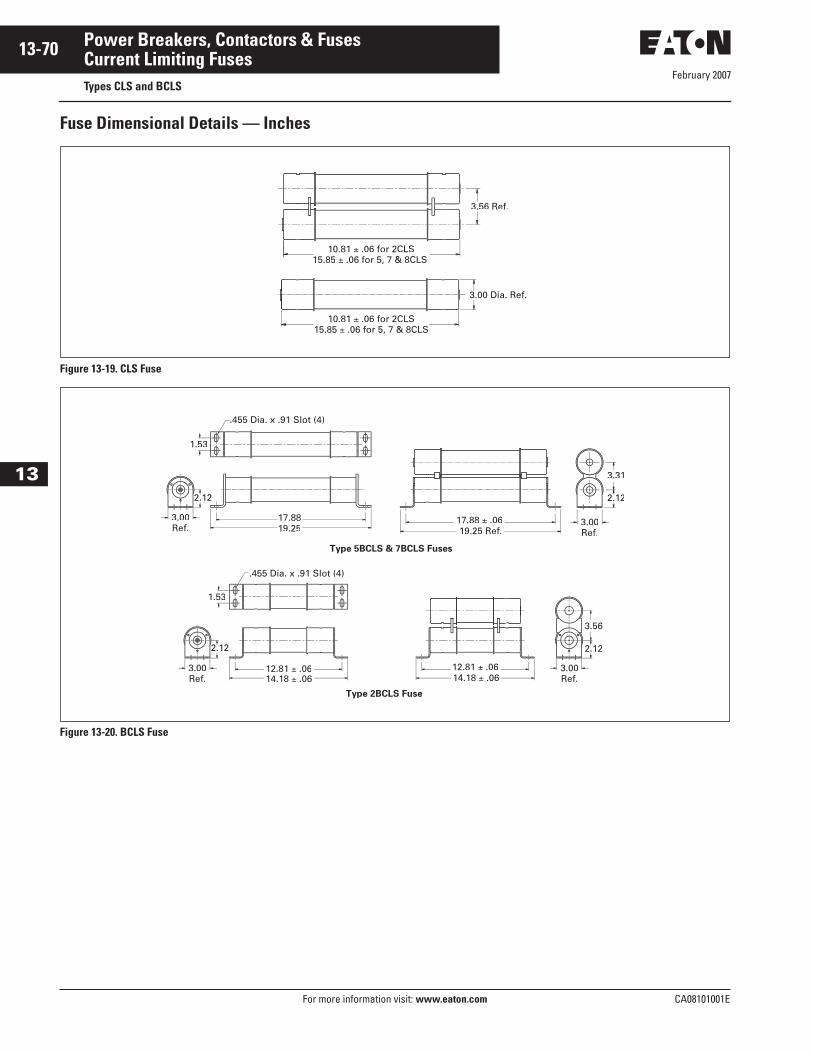
February 2007
13-70
For more information visit: www.eaton.com CA08101001E
Power Breakers, Contactors & Fuses
13
Current Limiting FusesTypes CLS and BCLS
Fuse Dimensional Details — Inches
Figure 13-19. CLS Fuse
Figure 13-20. BCLS Fuse
10.81 ± .06 for 2CLS15.85 ± .06 for 5, 7 & 8CLS
± .06 for 2CLS15.85 ±
3.56 Ref.
3.00Ref.
1.53
Type 2BCLS Fuse
Type 5BCLS & 7BCLS Fuses
14.18 ± .0612.81 ± .06
19.2517.88
14.18 ± .0612.81 ± .06
17.88 ± .0619.25 Ref.
.455 Dia. x .91 Slot (4)
1.53
3.31
2.12
3.00Ref.
3.00Ref.
3.00Ref.
February 2007
CA08101001E For more information visit: www.eaton.com
13-71Power Breakers, Contactors & Fuses
13
Current Limiting FusesType CLPT
Table 13-58. Type CLPT Current Limiting Fuses
� Includes end fittings.� Disconnect only.
Maxim
um
Desig
n
Vo
ltag
e (
kV
)
Cu
rren
t R
ati
ng
(Am
pere
s)
Catalog
Number
Inte
rru
pti
ng
Rati
ng
rm
s
Dia
mete
r (I
nch
es)
Clip
Cen
ter
(In
ch
es)
Len
gth
(In
ch
es)
Ap
pro
x. S
hip
pin
g
Weig
ht
(lb
s.)
Mounting
(Includes Live Parts, End Fittings)
Catalog Number Performance
Curves
Type
Vo
ltag
e (
BIL
) kV
Catalog Number Live
Parts �End
Fittings �
Min
imu
m
Melt
ing
Tim
e
To
tal C
leari
ng
Tim
e
Peak L
et-
Th
rou
gh
Cu
rren
t
Porcelain Glass-
Polyester
2.475 kV Maximum (2.4 kV Nominal)Indicating 0.25E
0.5E 1E 2E 5E
2NCLPT-.25E
2NCLPT-.5E
2NCLPT-1E
2NCLPT-2E
2NCLPT-5E
6363404025
0.810.810.810.810.81
—————
4.54.54.54.54.5
0.250.250.250.250.25
Not applicable.
5635
7202
5988
3702
6393
3702
5.5 kV Maximum (4.8 kV Nominal)Non-Indicating 0.5E
1E 2E 3E 4E 5E 0.5E 1E 2E 3E 5E
5NCLPT-.5E
5NCLPT-1E
5NCLPT-2E
5NCLPT-3E
5NCLPT-4E
5NCLPT-5E
317B487H02
317B487H06
317B487H03
317B487H04
317B487H05
6363636363635050505050
0.810.810.810.810.810.8111111
———————————
5.635.635.635.635.635.635.635.635.635.635.63
0.250.250.250.250.250.250.250.250.250.250.25
Not applicable.
6670
2402
6670
2502
6670
4101
Indicating 0.5E 1E 1.5E 3E 5E10E
5CLPT-.5E
5CLPT-1E
5CLPT-1.5E
5CLPT-3E
5CLPT-5E
5CLPT-10E
808080808080
1.61.61.61.61.61.6
8.18.18.18.18.18.1
9.59.59.59.59.59.5
1.21.21.21.21.21.2
Non-Disconnect
60 5CLPT-PNM-A 5CLPT-GNM-A CLPT-NL —
5635
3206
5635
3306
6393
4001Disconnect 60 5CLPT-PDM-A 5CLPT-GDM-A CLPT-DL CLPT-DF
0.5E 1E 2E 3E 5E10E
5NCLPT-.5E-A
5NCLPT-1E-A
5NCLPT-2E-A
5NCLPT-3E-A
5NCLPT-5E-A
5NCLPT-10E-A
636363636363
1.61.61.61.61.61.6
8.18.18.18.18.18.1
9.59.59.59.59.59.5
1.21.21.21.21.21.2
Non-Disconnect
60 5CLPT-PNM-A 5CLPT-GNM-A CLPT-NL —
7054
8302
7054
8402
6393
4002Disconnect 60 5CLPT-PDM-A 5CLPT-GDM-A CLPT-DL CLPT-DF
8.3 kV Maximum (7.2 kV Nominal) 2E4E1E5E10E
8NCLPT-2E
8NCLPT-4E
8NCLPT-1E
8NCLPT-5E
8NCLPT-0E
2525505050
0.810.811.11.11.1
88555
0.250.250.50.50.5
Not applicable.
5635
7206
5988
3706
6393
3704
.5E 8CLPT-.5E 80 1.6 8.1 9.5 1.5 Non-Disconnect
75 8CLPT-PNM-A 8CLPT-GNM-A CLPT-NL —
5635
3206
5635
3306
6393
4001
Disconnect 75 8CLPT-PDM-A 8CLPT-GDM-A CLPT-DL CLPT-DF
3E5E10E
8CLPT-3E
8CLPT-5E
8CLPT-10E
805050
1.61.61.6
11.511.511.5
12.912.912.9
1.51.51.5
Non-Disconnect
75 8CLPT-PNM-B 8CLPT-GNM-B CLPT-NL —
Disconnect 75 8CLPT-PDM-B 8CLPR-GDM-B CLPT-DL CLPT-DF
0.5E1E2E
8NCLPT-.5E-A
8NCLPT-1E-A
8NCLPT-2E-A
505050
1.61.61.6
8.18.18.1
9.59.59.5
1.51.51.5
Non-Disconnect
75 8CLPT-PNM-A 8CLPT-GNM-A CLPT-NL —
7054
8303
7054
8403
6393
4002
Disconnect 75 8CLPT-PDM-A 8CLPT-GDM-A CLPT-DL CLPT-DF
3E5E10E
8NCLPT-3E-A
8NCLPT-5E-A
8NCLPT-10E-A
505050
1.61.61.6
11.511.511.5
12.912.912.9
1.61.61.6
Non-Disconnect
75 8CLPT-PNM-B 8CLPT-GNM-B CLPT-NL —
Disconnect 75 8CLPT-PDM-B 8CLPT-GDM-B CLPT-DL CLPT-DF
February 2007
13-72
For more information visit: www.eaton.com CA08101001E
Power Breakers, Contactors & Fuses
13
Current Limiting FusesType CLPT
Table 13-58. Type CLPT Current Limiting Fuses (Continued)
� Includes end fittings.� Disconnect only.
Maxim
um
Desig
n
Vo
ltag
e (
kV
)
Cu
rren
t R
ati
ng
(Am
pere
s)
Catalog
Number
Inte
rru
pti
ng
Rati
ng
rm
s
Dia
mete
r (I
nch
es)
Clip
Cen
ter
(In
ch
es)
Len
gth
(In
ch
es)
Ap
pro
x. S
hip
pin
g
Weig
ht
(lb
s.)
Mounting
(Includes Live Parts, End Fittings)
Catalog Number Performance
Curves
Type
Vo
ltag
e (
BIL
) kV
Catalog Number Live
Parts �End
Fittings �
Min
imu
m
Melt
ing
Tim
e
To
tal C
leari
ng
Tim
e
Peak L
et-
Th
rou
gh
Cu
rren
t
Porcelain Glass-
Polyester
15.5 kV Maximum (7.2 kV Nominal)0.5E1E2E
15CLPT-.5E
15CLPT-1E
15CLPT-1.5E
808080
1.61.61.6
11.511.511.5
12.912.912.9
1.61.61.6
Non-Disconnect
95 15CLPT-PNM-A 15CLPT-GNM-A CLPT-NL —
5635
3206
5635
3306
6393
4001
Disconnect 95 15CLPT-PDM-A 15CLPT-GDM-A CLPT-DL CLPT-DF
3E5E10E
15CLPT-3E
15CLPT-5E
15CLPT-10E
808050
1.61.61.6
16.116.116.1
17.617.617.6
1.61.61.6
Non-Disconnect
95 15CLPT-PNM-B 15CLPT-GNM-B CLPT-NL —
Disconnect 95 15CLPT-PDM-B 15CLPT-GDM-B CLPT-DL CLPT-DF
0.5E1E2E
15NCLPT-.5E
15NCLPT-1E
15NCLPT-1.5E
636363
1.61.61.6
11.511.511.5
12.912.912.9
1.61.61.6
Non-Disconnect
95 15CLPT-PNM-A 15CLPT-GNM-A CLPT-NL —
7054
8303
7054
8403
6393
4002
Disconnect 95 15CLPT-PDM-A 15CLPT-GDM-A CLPT-DL CLPT-DF
3E5E10E
15NCLPT-3E
15NCLPT-5E
15NCLPT-10E
636363
1.61.61.6
16.116.116.1
17.617.617.6
1.61.61.6
Non-Disconnect
95 15CLPT-PNM-B 15CLPT-GNM-B CLPT-NL —
Disconnect 95 15CLPT-PDM-B 15CLPT-GDM-B CLPT-DL CLPT-DF
25.5 kV Maximum (14.4 kV Nominal)0.5E1E
25CLPT-.5E
25CLPT-1E
4444
1.61.6
16.116.1
17.617.6
22
Non-Disconnect
Not applicable. 25CLPT-NL —
5635
3208
5635
3308
6393
3901
Disconnect 25CLPT-DL CLPT-DF
38.0 kV Maximum (34.5 kV Nominal)0.5E 38CLPT-.5E 44 1.6 17.1 18.6 2 Non-
DisconnectNot applicable. 25CLPT-NL —
5635
3208
5635
3308
6393
3901
Disconnect 25CLPT-DL CLPT-DF
February 2007
CA08101001E For more information visit: www.eaton.com
13-73Power Breakers, Contactors & Fuses
13
Current Limiting FusesType CLPT
Table 13-59. Type CLPT Current Limiting Fuses
� See Page 13-79 for diagram of typical mounting.� End fittings supplied only when required.
Ampere
Rating
Fuse Mounting
Type �Voltage
BIL (kV)
Mounting (Including Live Parts,
End Fittings) �Live Parts
(Including
End Fittings) �
End Fittings
(Disconnect
Only)
Porcelain
Insulator
Glass-Polyester
Insulator
Catalog
Number
Catalog
Number
Catalog
Number
Catalog
Number
CLPT Mountings and Hardware2.475 kV Maximum (2.4 kV Nominal)Consult Factory
CLPT Mountings and Hardware5.5 kV Maximum (4.8 kV Nominal)0.5 to 1.5 Non-Disconnect
Disconnect 60 60
5CLPT-PNM-A
5CLPT-PDM-A
5CLPT-GNM-A
5CLPT-GDM-A
CLPT-NL
—
—
—
3 to 10 Non-DisconnectDisconnect
60 60
5CLPT-PNM-B
5CLPT-PDM-B
5CLPT-GNM-B
5CLPT-GDM-B
CLPT-NL
—
—
—
CLPT Mountings and Hardware8.3 kV Maximum (7.2 kV Nominal)0.5 Non-Disconnect
Disconnect 75 75
8CLPT-PNM-A
8CLPT-PDM-A
8CLPT-GNM-A
8CLPT-GDM-A
CLPT-NL
CLPT-DL
—
CLPT-DF
3 to 10 Non-DisconnectDisconnect
75 75
8CLPT-PNM-B
8CLPT-PDM-B
8CLPT-GNM-B
8CLPT-GDM-B
CLPT-NL
CLPT-DL
—
CLPT-DF
CLPT Mountings and Hardware15.5 kV Maximum (14.4 kV Nominal)0.5 to 1.5 Non-Disconnect
Disconnect 95 95
15CLPT-PNM-A
15CLPT-PDM-A
15CLPT-GNM-A
15CLPT-GDM-A
CLPT-NL
CLPT-DL
—
CLPT-DF
3 to 10 Non-DisconnectDisconnect
95 95
15CLPT-PNM-B
15CLPT-PDM-B
15CLPT-GNM-B
15CLPT-GDM-B
—
—
—
—
CLPT Mountings and Hardware25.5 kV Maximum (23.0 kV Nominal)0.5 to 1.5 Non-Disconnect
Disconnect150150
25CLPT-PNM-A
25CLPT-PDM-A
—
—
25CLPT-NL
25CLPT-DL
—
—
CLPT Mountings and Hardware38.0 kV Maximum (34.5 kV Nominal)Consult Factory
February 2007
13-74
For more information visit: www.eaton.com CA08101001E
Power Breakers, Contactors & Fuses
13
Current Limiting FusesType CX
Table 13-60. Type CX Current Limiting Fuses
� Includes end fittings.� Disconnect only.
Maxim
um
Desig
n
Vo
ltag
e (
kV
)
Cu
rren
t R
ati
ng
(Am
pere
s)
Catalog
Number
Barr
el N
um
ber
Inte
rru
pti
ng
Rati
ng
rm
s
(kA
Sym
.)
Dia
mete
r (I
nch
es)
Len
gth
(In
ch
es)
Ap
pro
x. S
hip
pin
g
Weig
ht
(lb
s.)
Mounting (Includes Live Parts,
End Fittings)
Catalog Number Performance Curves
Type
Vo
ltag
e (
BIL
) kV
Catalog
Number
Glass-
Polyester
Live
Parts �End
Fittings �Minimum
Melting
Time
Total
Clearing
Time
Peak
Let-
Through
Current
I2t
4.3 kV Maximum (2.4 kV Nominal) 18C 25C 35C 45C 50C 60C 65C 75C 80C100C
4CX-18C
4CX-25C
4CX-35C
4CX-45C
4CX-50C
4CX-60C
4CX-65C
4CX-75C
4CX-80C
4CX-100C
1111111111
50505050505050505050
1.131.1322222222
10101010101010101010
1112222222
Non-Disconnect
60 5CX-GNM-G CX-NL — 70544101 70544501 70544901 70545101
Disconnect 60 5CX-GDM-G CX-DL CX-DF 70544102 70544502
70544101 70544501
70544102 70544502
70544101 70544501
5.5 kV Maximum (4.8 kV Nominal) 10C 12C 18C 20C 21C 25C 30C 35C 40C 50C 60C 65C 75C
5CX-10C
5CX-12C
5CX-18C
5CX-20C
5CX-21C
5CX-25C
5CX-30C
5CX-35C
5CX-40C
5CX-50C
5CX-60C
5CX-65C
5CX-75C
1111111111111
50505050505050505050505050
1.131.131.131.13221.13222222
10101010101010101010101010
1111221222222
Non-Disconnect
60 5CX-GNM-G CX-NL — 70544201 70544601 70544902 70545201
70544202 70544602
70544201 70544602
Disconnect 60 5CX-GDM-G CX-DL CX-DF 70544202 70544602
70544201 70544602
70544202 70544602
70544201 70544601
8.3 kV Maximum (7.2 kV Nominal) 3.5C 4C 4.5C 6C 7C 8C 10C 12C 15C 18C 20C 25C 30C 35C 40C
8CX-3.5C
8CX-4C
8CX-4.5C
8CX-6C
8CX-7C
8CX-8C
8CX-10C
8CX-12C
8CX-15C
8CX-18C
8CX-20C
8CX-25C
8CX-30C
8CX-35C
8CX-40C
111111111111111
505050505050505050505050505050
1.131.131.131.131.131.131.131.131.13222222
101010101010101010101010101010
222222222222222
Non-Disconnect
75 8CX-GNM-G CX-NL — 70544302 70544702 70545001 70545301
70544301 70544701
70544302 70544702
70544301 70544701
Disconnect 75 8CX-GDM-G CX-DL CX-DF 70544302 70544702
70544301 70544701
70544302 70544702
70544301 70544701
15.5 kV Maximum (14.4 kV Nominal) 4C 6C 7C 8C 10C 12C 15C 18C 20C 25C 30C 40C
15CX- 4C
15CX- 6C
15CX- 7C
15CX- 8C
15CX- 10C
15CX- 12C
15CX- 15C
15CX- 18C
15CX- 20C
15CX- 25C
15CX- 30C
15CX- 40C
111111111111
505050505050505050505050
222222222222
14.314.314.314.314.314.314.314.314.314.314.314.3
2 2 2 2 2 2 2 2 2 2 2 2
Non- Disconnect
95 15CX-GNM-G CX-NL — 70544401 70544801 70545002 40545401
70544402 70544802
70544101 70544801
Disconnect 95 15CX-GDM-G CX-DL CX-DF 70544402 70544802
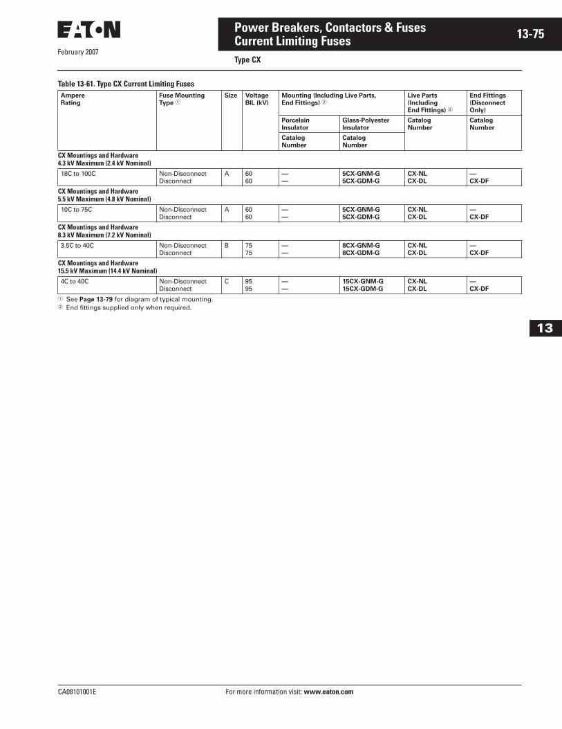
February 2007
CA08101001E For more information visit: www.eaton.com
13-75Power Breakers, Contactors & Fuses
13
Current Limiting FusesType CX
Table 13-61. Type CX Current Limiting Fuses
� See Page 13-79 for diagram of typical mounting.� End fittings supplied only when required.
Ampere
Rating
Fuse Mounting
Type �Size Voltage
BIL (kV)
Mounting (Including Live Parts,
End Fittings) �Live Parts
(Including
End Fittings) �
End Fittings
(Disconnect
Only)
Porcelain
Insulator
Glass-Polyester
Insulator
Catalog
Number
Catalog
Number
Catalog
Number
Catalog
Number
CX Mountings and Hardware4.3 kV Maximum (2.4 kV Nominal)18C to 100C Non-Disconnect
DisconnectA 60
60—
—
5CX-GNM-G
5CX-GDM-G
CX-NL
CX-DL
—
CX-DF
CX Mountings and Hardware5.5 kV Maximum (4.8 kV Nominal)10C to 75C Non-Disconnect
DisconnectA 60
60—
—
5CX-GNM-G
5CX-GDM-G
CX-NL
CX-DL
—
CX-DF
CX Mountings and Hardware8.3 kV Maximum (7.2 kV Nominal)3.5C to 40C Non-Disconnect
DisconnectB 75
75—
—
8CX-GNM-G
8CX-GDM-G
CX-NL
CX-DL
—
CX-DF
CX Mountings and Hardware15.5 kV Maximum (14.4 kV Nominal)4C to 40C Non-Disconnect
DisconnectC 95
95—
—
15CX-GNM-G
15CX-GDM-G
CX-NL
CX-DL
—
CX-DF
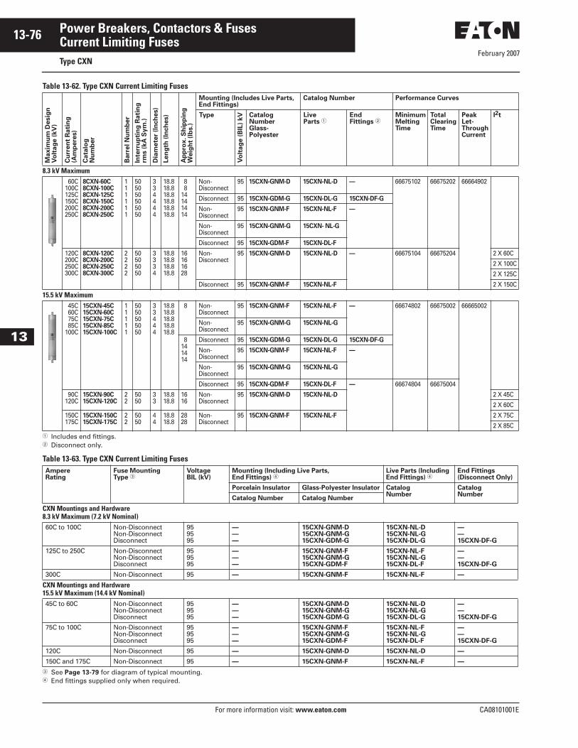
February 2007
13-76
For more information visit: www.eaton.com CA08101001E
Power Breakers, Contactors & Fuses
13
Current Limiting FusesType CXN
Table 13-62. Type CXN Current Limiting Fuses
� Includes end fittings.� Disconnect only.
Table 13-63. Type CXN Current Limiting Fuses
� See Page 13-79 for diagram of typical mounting.� End fittings supplied only when required.
Ma
xim
um
De
sig
nV
olt
ag
e (
kV
)
Cu
rre
nt
Ra
tin
g(A
mp
ere
s)
Ca
talo
gN
um
be
r
Ba
rre
l N
um
be
r
Inte
rru
pti
ng
Ra
tin
g
rms (
kA
Sy
m.)
Dia
me
ter
(In
ch
es)
Le
ng
th (
Inch
es)
Ap
pro
x. S
hip
pin
gW
eig
ht
(lb
s.)
Mounting (Includes Live Parts, End Fittings)
Catalog Number Performance Curves
Type
Vo
lta
ge
(B
IL)
kV Catalog
NumberGlass-Polyester
LiveParts �
EndFittings �
MinimumMeltingTime
TotalClearingTime
Peak Let-ThroughCurrent
I2t
8.3 kV Maximum 60C100C125C150C200C250C
8CXN-60C8CXN-100C8CXN-125C8CXN-150C8CXN-200C8CXN-250C
111111
505050505050
334444
18.818.818.818.818.818.8
8 814141414
Non- Disconnect
95 15CXN-GNM-D 15CXN-NL-D — 66675102 66675202 66664902
Disconnect 95 15CXN-GDM-G 15CXN-DL-G 15CXN-DF-G
Non- Disconnect
95 15CXN-GNM-F 15CXN-NL-F —
Non- Disconnect
95 15CXN-GNM-G 15CXN- NL-G
Disconnect 95 15CXN-GDM-F 15CXN-DL-F
120C200C250C300C
8CXN-120C8CXN-200C8CXN-250C8CXN-300C
2222
50505050
3334
18.818.818.818.8
16161628
Non- Disconnect
95 15CXN-GNM-D 15CXN-NL-D — 66675104 66675204 2 X 60C
2 X 100C
2 X 125C
Disconnect 95 15CXN-GNM-F 15CXN-NL-F 2 X 150C
15.5 kV Maximum 45C 60C 75C 85C100C
15CXN-45C15CXN-60C15CXN-75C15CXN-85C15CXN-100C
11111
5050505050
33444
18.818.818.818.818.8
8 Non- Disconnect
95 15CXN-GNM-F 15CXN-NL-F — 66674802 66675002 66665002
Non- Disconnect
95 15CXN-GNM-G 15CXN-NL-G
8141414
Disconnect 95 15CXN-GDM-G 15CXN-DL-G 15CXN-DF-G
Non- Disconnect
95 15CXN-GNM-F 15CXN-NL-F —
Non- Disconnect
95 15CXN-GNM-G 15CXN-NL-G
Disconnect 95 15CXN-GDM-F 15CXN-DL-F — 66674804 66675004
90C120C
15CXN-90C15CXN-120C
22
5050
33
18.818.8
1616
Non- Disconnect
95 15CXN-GNM-D 15CXN-NL-D 2 X 45C
2 X 60C
150C175C
15CXN-150C15CXN-175C
22
5050
44
18.818.8
2828
Non- Disconnect
95 15CXN-GNM-F 15CXN-NL-F 2 X 75C
2 X 85C
AmpereRating
Fuse MountingType �
VoltageBIL (kV)
Mounting (Including Live Parts, End Fittings) �
Live Parts (IncludingEnd Fittings) �
End Fittings(Disconnect Only)
Porcelain Insulator Glass-Polyester Insulator CatalogNumber
CatalogNumber
Catalog Number Catalog Number
CXN Mountings and Hardware8.3 kV Maximum (7.2 kV Nominal)60C to 100C Non-Disconnect
Non-DisconnectDisconnect
959595
———
15CXN-GNM-D15CXN-GNM-G15CXN-GDM-G
15CXN-NL-D15CXN-NL-G15CXN-DL-G
——15CXN-DF-G
125C to 250C Non-DisconnectNon-DisconnectDisconnect
959595
———
15CXN-GNM-F15CXN-GNM-G15CXN-GDM-F
15CXN-NL-F15CXN-NL-G15CXN-DL-F
——15CXN-DF-G
300C Non-Disconnect 95 — 15CXN-GNM-F 15CXN-NL-F —
CXN Mountings and Hardware15.5 kV Maximum (14.4 kV Nominal)45C to 60C Non-Disconnect
Non-DisconnectDisconnect
959595
———
15CXN-GNM-D15CXN-GNM-G15CXN-GDM-G
15CXN-NL-D15CXN-NL-G15CXN-DL-G
——15CXN-DF-G
75C to 100C Non-DisconnectNon-DisconnectDisconnect
959595
———
15CXN-GNM-F15CXN-GNM-G15CXN-GDM-F
15CXN-NL-F15CXN-NL-G15CXN-DL-F
——15CXN-DF-G
120C Non-Disconnect 95 — 15CXN-GNM-D 15CXN-NL-D —
150C and 175C Non-Disconnect 95 — 15CXN-GNM-F 15CXN-NL-F —
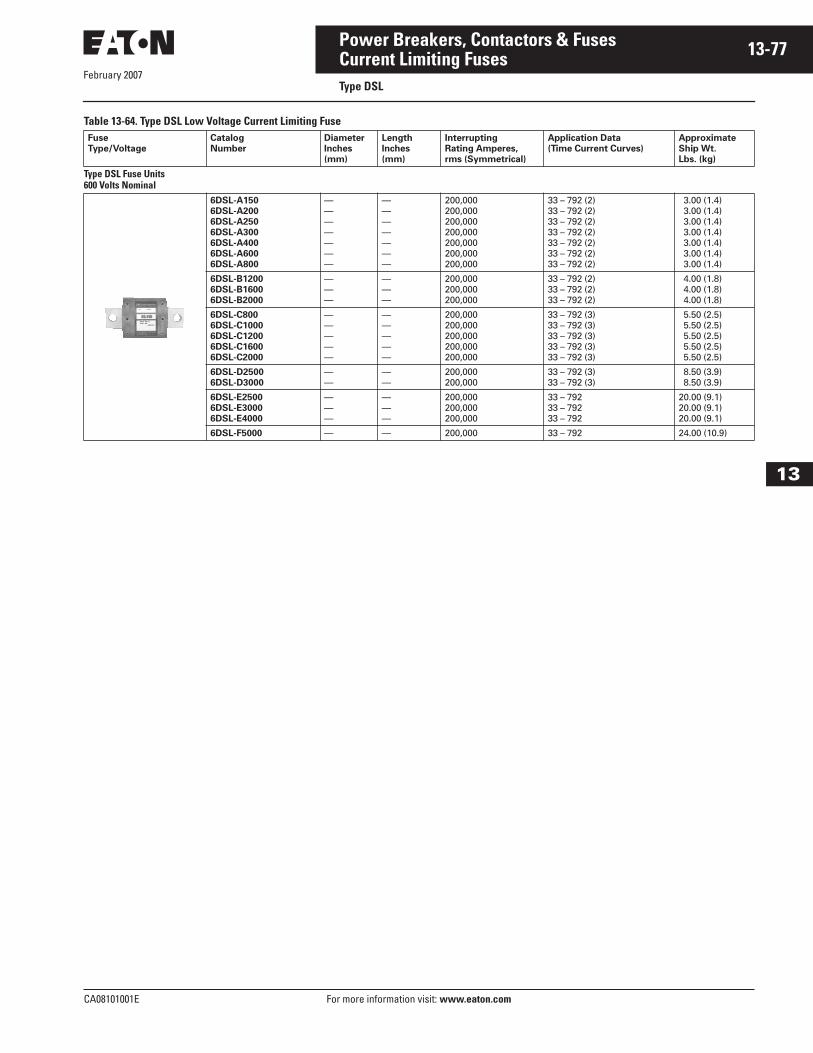
February 2007
CA08101001E For more information visit: www.eaton.com
13-77Power Breakers, Contactors & Fuses
13
Current Limiting FusesType DSL
Table 13-64. Type DSL Low Voltage Current Limiting FuseFuse
Type/Voltage
Catalog
Number
Diameter
Inches
(mm)
Length
Inches
(mm)
Interrupting
Rating Amperes,
rms (Symmetrical)
Application Data
(Time Current Curves)
Approximate
Ship Wt.
Lbs. (kg)
Type DSL Fuse Units600 Volts Nominal
6DSL-A150
6DSL-A200
6DSL-A250
6DSL-A300
6DSL-A400
6DSL-A600
6DSL-A800
———————
———————
200,000200,000200,000200,000200,000200,000200,000
33 – 792 (2)33 – 792 (2)33 – 792 (2)33 – 792 (2)33 – 792 (2)33 – 792 (2)33 – 792 (2)
3.00 (1.4) 3.00 (1.4) 3.00 (1.4) 3.00 (1.4) 3.00 (1.4) 3.00 (1.4) 3.00 (1.4)
6DSL-B1200
6DSL-B1600
6DSL-B2000
———
———
200,000200,000200,000
33 – 792 (2)33 – 792 (2)33 – 792 (2)
4.00 (1.8) 4.00 (1.8) 4.00 (1.8)
6DSL-C800
6DSL-C1000
6DSL-C1200
6DSL-C1600
6DSL-C2000
—————
—————
200,000200,000200,000200,000200,000
33 – 792 (3)33 – 792 (3)33 – 792 (3)33 – 792 (3)33 – 792 (3)
5.50 (2.5) 5.50 (2.5) 5.50 (2.5) 5.50 (2.5) 5.50 (2.5)
6DSL-D2500
6DSL-D3000
——
——
200,000200,000
33 – 792 (3)33 – 792 (3)
8.50 (3.9) 8.50 (3.9)
6DSL-E2500
6DSL-E3000
6DSL-E4000
———
———
200,000200,000200,000
33 – 792 33 – 792 33 – 792
20.00 (9.1)20.00 (9.1)20.00 (9.1)
6DSL-F5000 — — 200,000 33 – 792 24.00 (10.9)
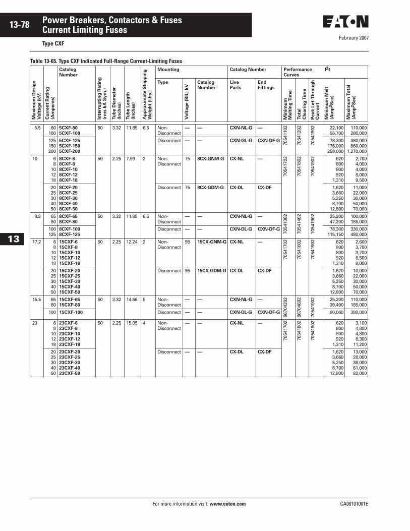
February 2007
13-78
For more information visit: www.eaton.com CA08101001E
Power Breakers, Contactors & Fuses
13
Current Limiting FusesType CXF
Table 13-65. Type CXF Indicated Full-Range Current-Limiting Fuses
Maxim
um
Desig
n
Vo
ltag
e (
kV
)
Cu
rren
t R
ati
ng
(Am
pere
s)
Catalog
Number
Inte
rru
pti
ng
Rati
ng
(rm
s k
A S
ym
.)
Tu
be D
iam
ete
r
(In
ch
es)
Tu
be L
en
gth
(In
ch
es)
Ap
pro
xim
ate
Sh
ipp
ing
Weig
ht
(Lb
s.)
Mounting Catalog Number Performance
Curves
I2t
Type
Vo
ltag
e (
BIL
) kV
Catalog
Number
Live
Parts
End
Fittings
Min
imu
mM
elt
ing
Tim
e
To
tal
Cle
ari
ng
Tim
e
Pe
ak
Le
t-T
hro
ug
hC
urr
en
t
Min
imu
m M
elt
(Am
p2S
ec)
Maxim
um
To
tal
(Am
p2S
ec)
5.5 80100
5CXF-80
5CXF-100
50 3.32 11.85 6.5 Non-Disconnect
— — CXN-NL-G —
7054
1102
7054
1202
7054
1902 22,100
56,700110,000280,000
125150200
5CXF-125
5CXF-150
5CXF-200
Disconnect — — CXN-GL-G CXN-DF-G 78,300176,000259,000
380,000860,000
1,270,000
10 68
101218
8CXF-6
8CXF-8
8CXF-10
8CXF-12
8CXF-18
50 2.25 7.93 2 Non-Disconnect
75 8CX-GNM-G CX-NL —
7054
1702
7054
1802
7054
1902 620
800800920
1,310
2,7004,0004,0008,0009,500
2025304050
8CXF-20
8CXF-25
8CXF-30
8CXF-40
8CXF-50
Disconnect 75 8CX-GDM-G CX-DL CX-DF 1,6203,6605,2508,700
12,800
11,00022,00030,00050,00070,000
8.3 6580
8CXF-65
8CXF-80
50 3.32 11.85 6.5 Non-Disconnect
— — CXN-NL-G —
7054
1302
7054
1402
7054
1902 25,200
47,200100,000185,000
100125
8CXF-100
8CXF-125
Disconnect — — CXN-DL-G CXN-DF-G 78,300115,150
330,000480,000
17.2 68
101218
15CXF-6
15CXF-8
15CXF-10
15CXF-12
15CXF-18
50 2.25 12.24 2 Non-Disconnect
95 15CX-GNM-G CX-NL —
7054
1702
7054
1802
7054
1902 620
800800920
1,310
2,6003,7003,7006,5008,000
2025304050
15CXF-20
15CXF-25
15CXF-30
15CXF-40
15CXF-50
Disconnect 95 15CX-GDM-G CX-DL CX-DF 1,6203,6605,2508,700
12,800
10,00022,00030,00050,00070,000
15.5 6580
15CXF-65
15CXF-80
50 3.32 14.66 8 Non-Disconnect
— — CXN-NL-G —
6670
4202
6670
4602
7054
1902 25,200
39,400110,000185,000
100 15CXF-100 Disconnect — — CXN-DL-G CXN-DF-G 80,000 380,000
23 68
101218
23CXF-6
23CXF-8
23CXF-10
23CXF-12
23CXF-18
50 2.25 15.05 4 Non-Disconnect
— — CX-NL —
7054
1702
7054
1802
7054
1902 620
800800920
1,310
3,1004,8004,8008,300
11,200
2025304050
23CXF-20
23CXF-25
23CXF-30
23CXF-40
23CXF-50
Disconnect — — CX-DL CX-DF 1,6203,6605,2508,700
12,800
13,00028,00038,00061,00082,000
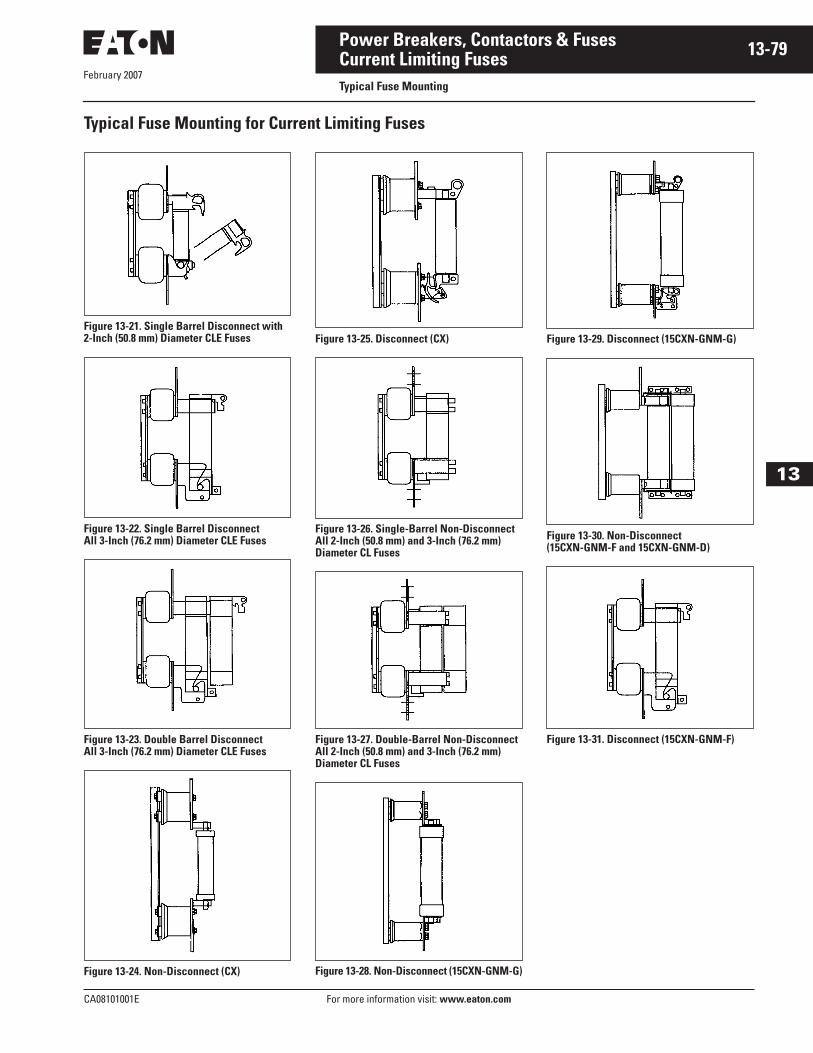
February 2007
CA08101001E For more information visit: www.eaton.com
13-79Power Breakers, Contactors & Fuses
13
Current Limiting FusesTypical Fuse Mounting
Typical Fuse Mounting for Current Limiting Fuses
Figure 13-21. Single Barrel Disconnect with2-Inch (50.8 mm) Diameter CLE Fuses
Figure 13-22. Single Barrel DisconnectAll 3-Inch (76.2 mm) Diameter CLE Fuses
Figure 13-23. Double Barrel DisconnectAll 3-Inch (76.2 mm) Diameter CLE Fuses
Figure 13-24. Non-Disconnect (CX)
Figure 13-25. Disconnect (CX)
Figure 13-26. Single-Barrel Non-Disconnect All 2-Inch (50.8 mm) and 3-Inch (76.2 mm) Diameter CL Fuses
Figure 13-27. Double-Barrel Non-Disconnect All 2-Inch (50.8 mm) and 3-Inch (76.2 mm) Diameter CL Fuses
Figure 13-28. Non-Disconnect (15CXN-GNM-G)
Figure 13-29. Disconnect (15CXN-GNM-G)
Figure 13-30. Non-Disconnect (15CXN-GNM-F and 15CXN-GNM-D)
Figure 13-31. Disconnect (15CXN-GNM-F)
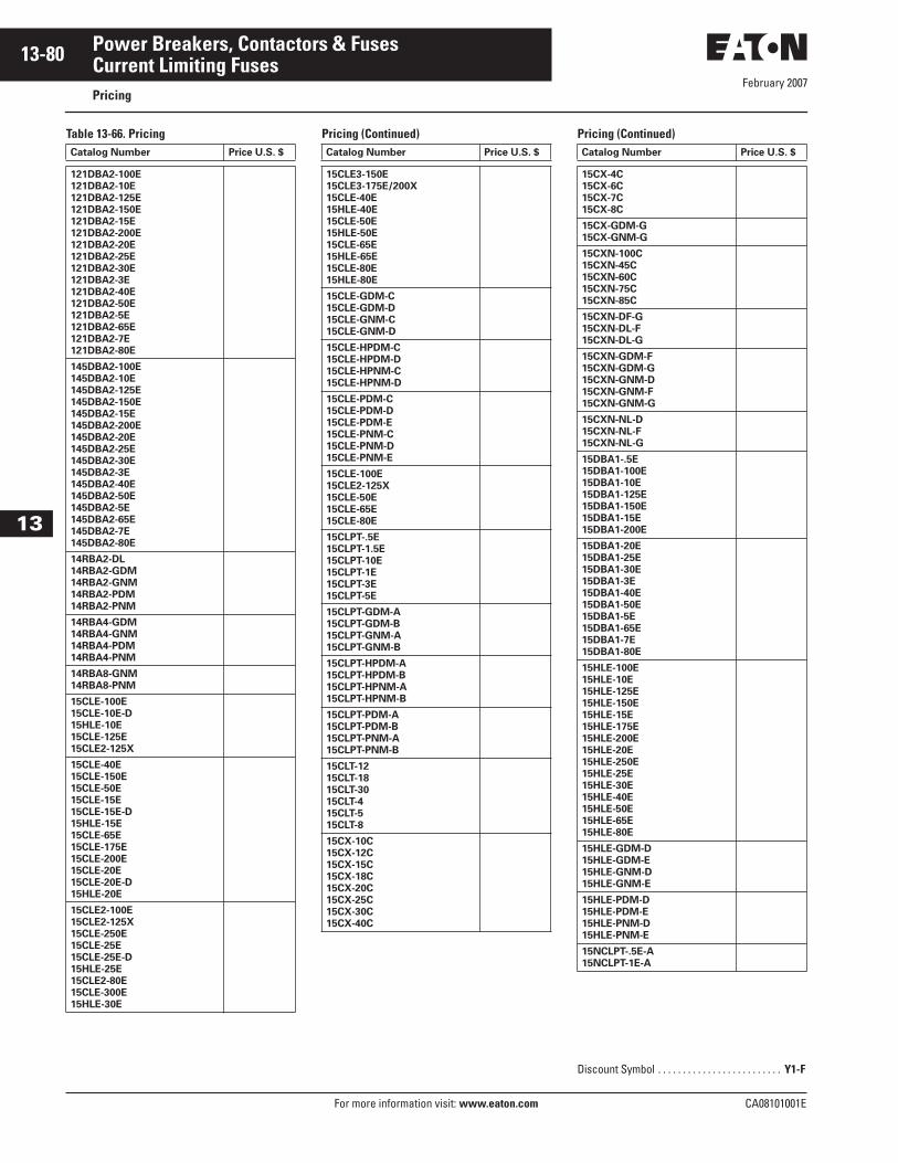
February 2007
13-80
For more information visit: www.eaton.com CA08101001E
Power Breakers, Contactors & Fuses
13
Current Limiting FusesPricing
Table 13-66. Pricing Pricing (Continued) Pricing (Continued)Catalog Number Price U.S. $
121DBA2-100E
121DBA2-10E
121DBA2-125E
121DBA2-150E
121DBA2-15E
121DBA2-200E
121DBA2-20E
121DBA2-25E
121DBA2-30E
121DBA2-3E
121DBA2-40E
121DBA2-50E
121DBA2-5E
121DBA2-65E
121DBA2-7E
121DBA2-80E
145DBA2-100E
145DBA2-10E
145DBA2-125E
145DBA2-150E
145DBA2-15E
145DBA2-200E
145DBA2-20E
145DBA2-25E
145DBA2-30E
145DBA2-3E
145DBA2-40E
145DBA2-50E
145DBA2-5E
145DBA2-65E
145DBA2-7E
145DBA2-80E
14RBA2-DL
14RBA2-GDM
14RBA2-GNM
14RBA2-PDM
14RBA2-PNM
14RBA4-GDM
14RBA4-GNM
14RBA4-PDM
14RBA4-PNM
14RBA8-GNM
14RBA8-PNM
15CLE-100E
15CLE-10E-D
15HLE-10E
15CLE-125E
15CLE2-125X
15CLE-40E
15CLE-150E
15CLE-50E
15CLE-15E
15CLE-15E-D
15HLE-15E
15CLE-65E
15CLE-175E
15CLE-200E
15CLE-20E
15CLE-20E-D
15HLE-20E
15CLE2-100E
15CLE2-125X
15CLE-250E
15CLE-25E
15CLE-25E-D
15HLE-25E
15CLE2-80E
15CLE-300E
15HLE-30E
Catalog Number Price U.S. $
15CLE3-150E
15CLE3-175E/200X
15CLE-40E
15HLE-40E
15CLE-50E
15HLE-50E
15CLE-65E
15HLE-65E
15CLE-80E
15HLE-80E
15CLE-GDM-C
15CLE-GDM-D
15CLE-GNM-C
15CLE-GNM-D
15CLE-HPDM-C
15CLE-HPDM-D
15CLE-HPNM-C
15CLE-HPNM-D
15CLE-PDM-C
15CLE-PDM-D
15CLE-PDM-E
15CLE-PNM-C
15CLE-PNM-D
15CLE-PNM-E
15CLE-100E
15CLE2-125X
15CLE-50E
15CLE-65E
15CLE-80E
15CLPT-.5E
15CLPT-1.5E
15CLPT-10E
15CLPT-1E
15CLPT-3E
15CLPT-5E
15CLPT-GDM-A
15CLPT-GDM-B
15CLPT-GNM-A
15CLPT-GNM-B
15CLPT-HPDM-A
15CLPT-HPDM-B
15CLPT-HPNM-A
15CLPT-HPNM-B
15CLPT-PDM-A
15CLPT-PDM-B
15CLPT-PNM-A
15CLPT-PNM-B
15CLT-12
15CLT-18
15CLT-30
15CLT-4
15CLT-5
15CLT-8
15CX-10C
15CX-12C
15CX-15C
15CX-18C
15CX-20C
15CX-25C
15CX-30C
15CX-40C
Catalog Number Price U.S. $
15CX-4C
15CX-6C
15CX-7C
15CX-8C
15CX-GDM-G
15CX-GNM-G
15CXN-100C
15CXN-45C
15CXN-60C
15CXN-75C
15CXN-85C
15CXN-DF-G
15CXN-DL-F
15CXN-DL-G
15CXN-GDM-F
15CXN-GDM-G
15CXN-GNM-D
15CXN-GNM-F
15CXN-GNM-G
15CXN-NL-D
15CXN-NL-F
15CXN-NL-G
15DBA1-.5E
15DBA1-100E
15DBA1-10E
15DBA1-125E
15DBA1-150E
15DBA1-15E
15DBA1-200E
15DBA1-20E
15DBA1-25E
15DBA1-30E
15DBA1-3E
15DBA1-40E
15DBA1-50E
15DBA1-5E
15DBA1-65E
15DBA1-7E
15DBA1-80E
15HLE-100E
15HLE-10E
15HLE-125E
15HLE-150E
15HLE-15E
15HLE-175E
15HLE-200E
15HLE-20E
15HLE-250E
15HLE-25E
15HLE-30E
15HLE-40E
15HLE-50E
15HLE-65E
15HLE-80E
15HLE-GDM-D
15HLE-GDM-E
15HLE-GNM-D
15HLE-GNM-E
15HLE-PDM-D
15HLE-PDM-E
15HLE-PNM-D
15HLE-PNM-E
15NCLPT-.5E-A
15NCLPT-1E-A
Discount Symbol . . . . . . . . . . . . . . . . . . . . . . . . . Y1-F

February 2007
CA08101001E For more information visit: www.eaton.com
13-81Power Breakers, Contactors & Fuses
13
Current Limiting FusesPricing
Table 13-66. Pricing (Continued) Pricing (Continued) Pricing (Continued)Catalog Number Price U.S. $
15RBA2-100E
15RBA2-10E
15RBA2-125E
15RBA2-150E
15RBA2-15E
15RBA2-200E
15RBA2-20E
15RBA2-25E
15RBA2-30E
15RBA2-40E
15RBA2-50E
15RBA2-65E
15RBA2-80E
15RBA2-DH
15RBA2-IDH
15RBA2-INH
15RBA2-ISHNT
15RBA2-LBDH
15RBA2-NH
15RBA2-NL
15RBA2-PDM
15RBA2-PNM
15RBA2-SHNT
15RBA4-.5E
15RBA4-100E
15RBA4-10E
15RBA4-125E
15RBA4-150E
15RBA4-15E
15RBA4-200E
15RBA4-20E
15RBA4-250E
15RBA4-25E
15RBA4-300E
15RBA4-30E
15RBA4-3E
15RBA4-400E
15RBA4-40E
15RBA4-50E
15RBA4-5E
15RBA4-65E
15RBA4-7E
15RBA4-80E
15RBA4-DH
15RBA4-DL
15RBA4-IDH
15RBA4-INH
15RBA4-ISHNT
15RBA4-LBDH
15RBA4-LBDL
15RBA4-NH
15RBA4-NL
15RBA4-PDM
15RBA4-PNM
15RBA4-SHNT
15RBA8-INH
15RBA8-NH
15RBA8-NL
15RBA8-PNM
15RBT2-100E
15RBT2-125E
15RBT2-150E
15RBT2-200E
15RBT2-20E
15RBT2-25E
15RBT2-30E
15RBT2-40E
15RBT2-50E
15RBT2-65E
15RBT2-80E
Catalog Number Price U.S. $
15RBT4-100E
15RBT4-125E
15RBT4-150E
15RBT4-200E
15RBT4-20E
15RBT4-250E
15RBT4-25E
15RBT4-300E
15RBT4-30E
15RBT4-400E
15RBT4-40E
15RBT4-50E
15RBT4-65E
15RBT4-80E
15RDB2-DH
15RDB2-HUM
15RDB2-HVM
15RDB2-SHNT
15RDB2-UM
15RDB2-VM
15RDB4-DH
15RDB4-HUM
15RDB4-SHNT
15RDB4-UM
15RDB4-VM
15RDB8-HUM
15RDB8-HVM
15RDB8-UM
15RDB8-VM
25CLPT-.5E
25CLPT-1E
25CLPT-DL
25CLPT-NL
25CLPT-PDM-A
25CLPT-PNM-A
25DBA1-.5E
25DBA1-100E
25DBA1-10E
25DBA1-125E
25DBA1-150E
25DBA1-15E
25DBA1-200E
25DBA1-20E
25DBA1-25E
25DBA1-30E
25DBA1-3E
25DBA1-40E
25DBA1-50E
25DBA1-5E
25DBA1-65E
25DBA1-7E
25DBA1-80E
25RBA2-100E
25RBA2-10E
25RBA2-125E
25RBA2-150E
25RBA2-15E
25RBA2-200E
25RBA2-20E
25RBA2-25E
25RBA2-30E
25RBA2-40E
25RBA2-50E
25RBA2-65E
25RBA2-80E
Catalog Number Price U.S. $
25RBA2-DH
25RBA2-IDH
25RBA2-INH
25RBA2-ISHNT
25RBA2-LBDH
25RBA2-NH
25RBA2-PDM
25RBA2-PNM
25RBA2-SHNT
25RBA4-.5E
25RBA4-100E
25RBA4-10E
25RBA4-125E
25RBA4-150E
25RBA4-15E
25RBA4-200E
25RBA4-20E
25RBA4-250E
25RBA4-25E
25RBA4-300E
25RBA4-30E
25RBA4-3E
25RBA4-40E
25RBA4-50E
25RBA4-5E
25RBA4-65E
25RBA4-7E
25RBA4-80E
25RBA4-DH
25RBA4-IDH
25RBA4-INH
25RBA4-ISHNT
25RBA4-LBDH
25RBA4-NH
25RBA4-PDM
25RBA4-PNM
25RBA4-SHNT
25RBA8-INH
25RBA8-NH
25RBA8-PNM
25RBT2-100E
25RBT2-125E
25RBT2-150E
25RBT2-200E
25RBT2-20E
25RBT2-25E
25RBT2-30E
25RBT2-40E
25RBT2-50E
25RBT2-65E
25RBT2-80E
25RBT4-100E
25RBT4-125E
25RBT4-150E
25RBT4-200E
25RBT4-20E
25RBT4-250E
25RBT4-25E
25RBT4-300E
25RBT4-30E
25RBT4-40E
25RBT4-50E
25RBT4-65E
25RBT4-80E
25RDB2-DH
25RDB2-HUM
25RDB2-HVM
25RDB2-SHNT
25RDB2-UM
25RDB2-VM
Discount Symbol . . . . . . . . . . . . . . . . . . . . . . . . . Y1-F
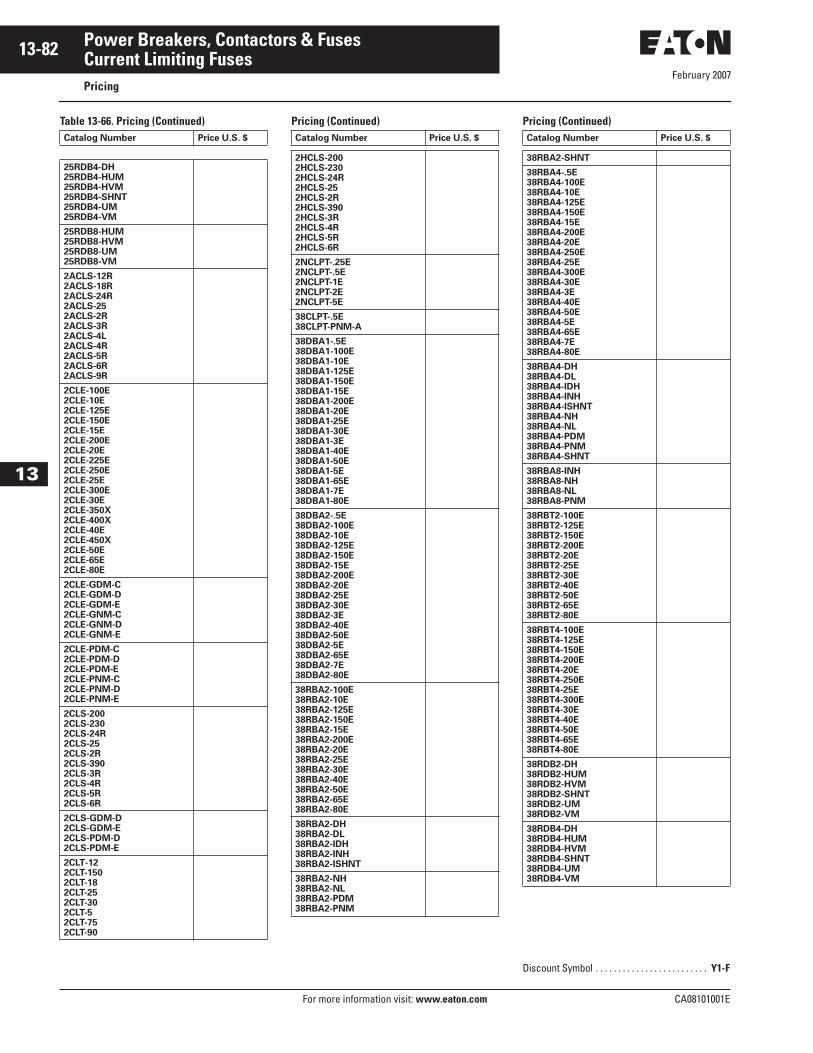
February 2007
13-82
For more information visit: www.eaton.com CA08101001E
Power Breakers, Contactors & Fuses
13
Current Limiting FusesPricing
Table 13-66. Pricing (Continued) Pricing (Continued) Pricing (Continued)Catalog Number Price U.S. $
25RDB4-DH25RDB4-HUM25RDB4-HVM25RDB4-SHNT25RDB4-UM25RDB4-VM
25RDB8-HUM25RDB8-HVM25RDB8-UM25RDB8-VM
2ACLS-12R2ACLS-18R2ACLS-24R2ACLS-252ACLS-2R2ACLS-3R2ACLS-4L2ACLS-4R2ACLS-5R2ACLS-6R2ACLS-9R
2CLE-100E2CLE-10E2CLE-125E2CLE-150E2CLE-15E2CLE-200E2CLE-20E2CLE-225E2CLE-250E2CLE-25E2CLE-300E2CLE-30E2CLE-350X2CLE-400X2CLE-40E2CLE-450X2CLE-50E2CLE-65E2CLE-80E
2CLE-GDM-C2CLE-GDM-D2CLE-GDM-E2CLE-GNM-C2CLE-GNM-D2CLE-GNM-E
2CLE-PDM-C2CLE-PDM-D2CLE-PDM-E2CLE-PNM-C2CLE-PNM-D2CLE-PNM-E
2CLS-2002CLS-2302CLS-24R2CLS-252CLS-2R2CLS-3902CLS-3R2CLS-4R2CLS-5R2CLS-6R
2CLS-GDM-D2CLS-GDM-E2CLS-PDM-D2CLS-PDM-E
2CLT-122CLT-1502CLT-182CLT-252CLT-302CLT-52CLT-752CLT-90
Catalog Number Price U.S. $
2HCLS-2002HCLS-2302HCLS-24R2HCLS-252HCLS-2R2HCLS-3902HCLS-3R2HCLS-4R2HCLS-5R2HCLS-6R
2NCLPT-.25E2NCLPT-.5E2NCLPT-1E2NCLPT-2E2NCLPT-5E
38CLPT-.5E38CLPT-PNM-A
38DBA1-.5E38DBA1-100E38DBA1-10E38DBA1-125E38DBA1-150E38DBA1-15E38DBA1-200E38DBA1-20E38DBA1-25E38DBA1-30E38DBA1-3E38DBA1-40E38DBA1-50E38DBA1-5E38DBA1-65E38DBA1-7E38DBA1-80E
38DBA2-.5E38DBA2-100E38DBA2-10E38DBA2-125E38DBA2-150E38DBA2-15E38DBA2-200E38DBA2-20E38DBA2-25E38DBA2-30E38DBA2-3E38DBA2-40E38DBA2-50E38DBA2-5E38DBA2-65E38DBA2-7E38DBA2-80E
38RBA2-100E38RBA2-10E38RBA2-125E38RBA2-150E38RBA2-15E38RBA2-200E38RBA2-20E38RBA2-25E38RBA2-30E38RBA2-40E38RBA2-50E38RBA2-65E38RBA2-80E
38RBA2-DH38RBA2-DL38RBA2-IDH38RBA2-INH38RBA2-ISHNT
38RBA2-NH38RBA2-NL38RBA2-PDM38RBA2-PNM
Catalog Number Price U.S. $
38RBA2-SHNT
38RBA4-.5E38RBA4-100E38RBA4-10E38RBA4-125E38RBA4-150E38RBA4-15E38RBA4-200E38RBA4-20E38RBA4-250E38RBA4-25E38RBA4-300E38RBA4-30E38RBA4-3E38RBA4-40E38RBA4-50E38RBA4-5E38RBA4-65E38RBA4-7E38RBA4-80E
38RBA4-DH38RBA4-DL38RBA4-IDH38RBA4-INH38RBA4-ISHNT38RBA4-NH38RBA4-NL38RBA4-PDM38RBA4-PNM38RBA4-SHNT
38RBA8-INH38RBA8-NH38RBA8-NL38RBA8-PNM
38RBT2-100E38RBT2-125E38RBT2-150E38RBT2-200E38RBT2-20E38RBT2-25E38RBT2-30E38RBT2-40E38RBT2-50E38RBT2-65E38RBT2-80E
38RBT4-100E38RBT4-125E38RBT4-150E38RBT4-200E38RBT4-20E38RBT4-250E38RBT4-25E38RBT4-300E38RBT4-30E38RBT4-40E38RBT4-50E38RBT4-65E38RBT4-80E
38RDB2-DH38RDB2-HUM38RDB2-HVM38RDB2-SHNT38RDB2-UM38RDB2-VM
38RDB4-DH38RDB4-HUM38RDB4-HVM38RDB4-SHNT38RDB4-UM38RDB4-VM
Discount Symbol . . . . . . . . . . . . . . . . . . . . . . . . . Y1-F

February 2007
CA08101001E For more information visit: www.eaton.com
13-83Power Breakers, Contactors & Fuses
13
Current Limiting FusesPricing
Table 13-66. Pricing (Continued) Pricing (Continued) Pricing (Continued)Catalog Number Price U.S. $
38RDB8-HUM
38RDB8-HVM
38RDB8-UM
38RDB8-VM
48DBA1-.5E
48DBA1-100E
48DBA1-10E
48DBA1-125E
48DBA1-150E
48DBA1-15E
48DBA1-200E
48DBA1-20E
48DBA1-25E
48DBA1-30E
48DBA1-3E
48DBA1-40E
48DBA1-50E
48DBA1-5E
48DBA1-65E
48DBA1-7E
48DBA1-80E
48DBA2-.5E
48DBA2-100E
48DBA2-10E
48DBA2-125E
48DBA2-150E
48DBA2-15E
48DBA2-200E
48DBA2-20E
48DBA2-25E
48DBA2-30E
48DBA2-3E
48DBA2-40E
48DBA2-50E
48DBA2-5E
48DBA2-65E
48DBA2-7E
48DBA2-80E
4ACLS-26R
4CX-100C
4CX-18C
4CX-25C
4CX-35C
4CX-45C
4CX-50C
4CX-60C
4CX-65C
4CX-75C
4CX-80C
5ACLE-100E
5AHLE-100E
5AHLE-10E
5ACLE-125E
5ACLE-150E
5AHLE-15E
5ACLE-200E
5AHLE-20E
5ACLE-225E
5ACLE-250E
5ACLE-25E
5AHLE-25E
5ACLE-300E
5ACLE-30E
5AHLE-30E
5ACLE-400X
5AHLE-40E
5ACLE-50E
Catalog Number Price U.S. $
5AHLE-50E
5ACLE-65E
5AHLE-65E
5ACLE-80E
5AHLE-80E
5ACLS-12R
5ACLS-18R
5ACLS-24R
5ACLS-2R
5ACLS-30
5ACLS-3R
5ACLS-4R
5ACLS-5R
5ACLS-6R
5ACLS-9R
5AHLE-100E
5AHLE-10E
5AHLE-125E
5AHLE-150E
5AHLE-15E
5AHLE-175E
5AHLE-200E
5AHLE-20E
5AHLE-250E
5AHLE-25E
5AHLE-300E
5AHLE-30E
5AHLE-350E
5AHLE-400E
5AHLE-40E
5AHLE-450E
5AHLE-50E
5AHLE-65E
5AHLE-80E
5HLE-100E
5CLE-10E-D
5HLE-10E
5CLE1-100E
5CLE1-10E
5CLE1-125E
5CLE1-225E
5CLE-30E
5CLE1-40E
5CLE1-50E
5CLE-15E
5CLE-15E-D
5HLE-15E
5CLE1-65E
5CLE-175E
5CLE1-80E
5CLE-20E
5CLE-20E-D
5HLE-20E
5CLE2-250E/280X
5CLE2-350X
5CLE2-365X
5CLE2-400X
5CLE2-450X
5CLE-25E
5CLE-25E-D
5CLE-300E
5CLE-30E
5HLE-30E
5CLE-350E
5CLE-400E
5HLE-40E
5CLE-450E
5HLE-50E
5CLE-600E
5HLE-65E
5CLE-750E
5HLE-80E
Catalog Number Price U.S. $
5CLE-GDM-C
5CLE-GDM-D
5CLE-GDM-E
5CLE-GNM-C
5CLE-GNM-D
5CLE-GNM-E
5CLE-PDM-C
5CLE-PDM-D
5CLE-PDM-E
5CLE-PNM-C
5CLE-PNM-D
5CLE-PNM-E
5CLPT-.5E
5CLPT-1.5E
5CLPT-10E
5CLPT-1E
5CLPT-3E
5CLPT-5E
5CLPT-GDM-A
5CLPT-GDM-B
5CLPT-GNM-A
5CLPT-GNM-B
5CLPT-PDM-A
5CLPT-PDM-B
5CLPT-PNM-A
5CLPT-PNM-B
5CLS-12R
5CLS-18R
5CLS-24R
5CLS-2R
5CLS-30
5CLS-3R
5CLS-4R
5CLS-5R
5CLS-6R
5CLS70-100E
5CLS70-125E
5CLS70-12R
5CLS70-150E
5CLS70-200E
5CLS70-24R
5CLS70-250E
5CLS70-2R
5CLS70-32R
5CLS70-36R
5CLS70-3R
5CLS70-44R
5CLS70-4R
5CLS70-5R
5CLS70-600E
5CLS70-6R
5CLS70-750E
5CLS70-80E
5CLS70-9R
5CLS75-24R
5CLS75-32R
5CLS75-36R
5CLS-9R
5CLS-GDM-D
5CLS-GDM-E
5CLS-HGDM-D
5CLS-HGDM-E
5CLS-HPDM-D
5CLS-HPDM-E
5CLS-PDM-D
5CLS-PDM-E
Discount Symbol . . . . . . . . . . . . . . . . . . . . . . . . . Y1-F
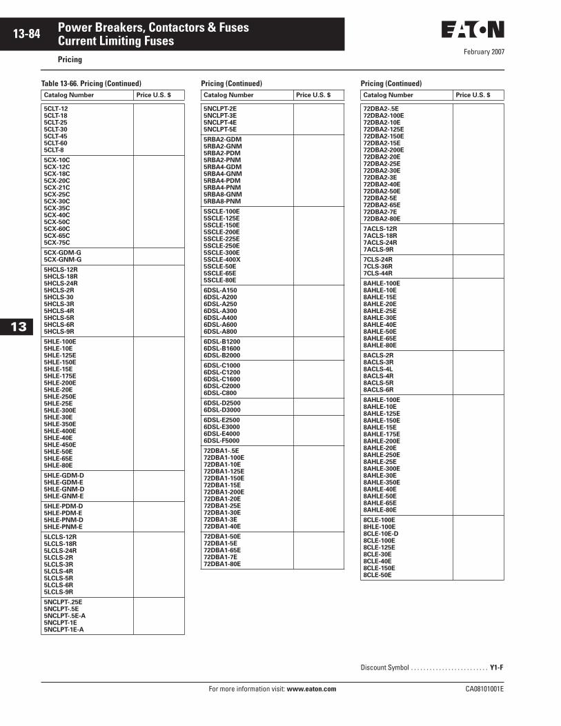
February 2007
13-84
For more information visit: www.eaton.com CA08101001E
Power Breakers, Contactors & Fuses
13
Current Limiting FusesPricing
Table 13-66. Pricing (Continued) Pricing (Continued) Pricing (Continued)Catalog Number Price U.S. $
5CLT-125CLT-185CLT-255CLT-305CLT-455CLT-605CLT-8
5CX-10C5CX-12C5CX-18C5CX-20C5CX-21C5CX-25C5CX-30C5CX-35C5CX-40C5CX-50C5CX-60C5CX-65C5CX-75C
5CX-GDM-G5CX-GNM-G
5HCLS-12R5HCLS-18R5HCLS-24R5HCLS-2R5HCLS-305HCLS-3R5HCLS-4R5HCLS-5R5HCLS-6R5HCLS-9R
5HLE-100E5HLE-10E5HLE-125E5HLE-150E5HLE-15E5HLE-175E5HLE-200E5HLE-20E5HLE-250E5HLE-25E5HLE-300E5HLE-30E5HLE-350E5HLE-400E5HLE-40E5HLE-450E5HLE-50E5HLE-65E5HLE-80E
5HLE-GDM-D5HLE-GDM-E5HLE-GNM-D5HLE-GNM-E
5HLE-PDM-D5HLE-PDM-E5HLE-PNM-D5HLE-PNM-E
5LCLS-12R5LCLS-18R5LCLS-24R5LCLS-2R5LCLS-3R5LCLS-4R5LCLS-5R5LCLS-6R5LCLS-9R
5NCLPT-.25E5NCLPT-.5E5NCLPT-.5E-A5NCLPT-1E5NCLPT-1E-A
Catalog Number Price U.S. $
5NCLPT-2E5NCLPT-3E5NCLPT-4E5NCLPT-5E
5RBA2-GDM5RBA2-GNM5RBA2-PDM5RBA2-PNM5RBA4-GDM5RBA4-GNM5RBA4-PDM5RBA4-PNM5RBA8-GNM5RBA8-PNM
5SCLE-100E5SCLE-125E5SCLE-150E5SCLE-200E5SCLE-225E5SCLE-250E5SCLE-300E5SCLE-400X5SCLE-50E5SCLE-65E5SCLE-80E
6DSL-A1506DSL-A2006DSL-A2506DSL-A3006DSL-A4006DSL-A6006DSL-A800
6DSL-B12006DSL-B16006DSL-B2000
6DSL-C10006DSL-C12006DSL-C16006DSL-C20006DSL-C800
6DSL-D25006DSL-D3000
6DSL-E25006DSL-E30006DSL-E40006DSL-F5000
72DBA1-.5E72DBA1-100E72DBA1-10E72DBA1-125E72DBA1-150E72DBA1-15E72DBA1-200E72DBA1-20E72DBA1-25E72DBA1-30E72DBA1-3E72DBA1-40E
72DBA1-50E72DBA1-5E72DBA1-65E72DBA1-7E72DBA1-80E
Catalog Number Price U.S. $
72DBA2-.5E72DBA2-100E72DBA2-10E72DBA2-125E72DBA2-150E72DBA2-15E72DBA2-200E72DBA2-20E72DBA2-25E72DBA2-30E72DBA2-3E72DBA2-40E72DBA2-50E72DBA2-5E72DBA2-65E72DBA2-7E72DBA2-80E
7ACLS-12R7ACLS-18R7ACLS-24R7ACLS-9R
7CLS-24R7CLS-36R7CLS-44R
8AHLE-100E8AHLE-10E8AHLE-15E8AHLE-20E8AHLE-25E8AHLE-30E8AHLE-40E8AHLE-50E8AHLE-65E8AHLE-80E
8ACLS-2R8ACLS-3R8ACLS-4L8ACLS-4R8ACLS-5R8ACLS-6R
8AHLE-100E8AHLE-10E8AHLE-125E8AHLE-150E8AHLE-15E8AHLE-175E8AHLE-200E8AHLE-20E8AHLE-250E8AHLE-25E8AHLE-300E8AHLE-30E8AHLE-350E8AHLE-40E8AHLE-50E8AHLE-65E8AHLE-80E
8CLE-100E8HLE-100E8CLE-10E-D8CLE-100E8CLE-125E8CLE-30E8CLE-40E8CLE-150E8CLE-50E
Discount Symbol . . . . . . . . . . . . . . . . . . . . . . . . . Y1-F
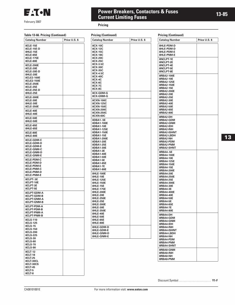
February 2007
CA08101001E For more information visit: www.eaton.com
13-85Power Breakers, Contactors & Fuses
13
Current Limiting FusesPricing
Table 13-66. Pricing (Continued) Pricing (Continued) Pricing (Continued)Catalog Number Price U.S. $
8CLE-15E
8CLE-15E-D
8HLE-15E
8CLE-65E
8CLE-175E
8CLE-80E
8CLE-200E
8CLE-20E
8CLE-20E-D
8HLE-20E
8CLE2-100E
8CLE2-150E
8CLE-250E
8CLE-25E
8CLE-25E-D
8HLE-25E
8CLE-300E
8CLE-30E
8HLE-30E
8CLE-350E
8CLE-40E
8HLE-40E
8CLE-50E
8HLE-50E
8CLE-65E
8HLE-65E
8CLE-80E
8HLE-80E
8CLE-GDM-C
8CLE-GDM-D
8CLE-GDM-E
8CLE-GNM-C
8CLE-GNM-D
8CLE-GNM-E
8CLE-PDM-C
8CLE-PDM-D
8CLE-PDM-E
8CLE-PNM-C
8CLE-PNM-D
8CLE-PNM-E
8CLPT-.5E
8CLPT-10E
8CLPT-3E
8CLPT-5E
8CLPT-GDM-A
8CLPT-GDM-B
8CLPT-GNM-A
8CLPT-GNM-B
8CLPT-PDM-A
8CLPT-PDM-B
8CLPT-PNM-A
8CLPT-PNM-B
8CLS-110
8CLS-125
8CLS-15
8CLS-150
8CLS-200
8CLS-225
8CLS-30
8CLS-60
8CLS-70
8CLS-90
8CLT-12
8CLT-18
8CLT-25
8CLT-30CL
8CLT-30CS
8CLT-45
8CLT-5
8CLT-8
Catalog Number Price U.S. $
8CX-10C
8CX-12C
8CX-15C
8CX-18C
8CX-20C
8CX-25C
8CX-3.5C
8CX-30C
8CX-35C
8CX-4.5C
8CX-40C
8CX-4C
8CX-6C
8CX-7C
8CX-8C
8CX-GDM-G
8CX-GNM-G
8CXN-100C
8CXN-125C
8CXN-150C
8CXN-200C
8CXN-250C
8CXN-60C
8DBA1-.5E
8DBA1-100E
8DBA1-10E
8DBA1-125E
8DBA1-150E
8DBA1-15E
8DBA1-200E
8DBA1-20E
8DBA1-25E
8DBA1-30E
8DBA1-3E
8DBA1-40E
8DBA1-50E
8DBA1-5E
8DBA1-65E
8DBA1-7E
8DBA1-80E
8HLE-100E
8HLE-10E
8HLE-125E
8HLE-150E
8HLE-15E
8HLE-175E
8HLE-200E
8HLE-20E
8HLE-250E
8HLE-25E
8HLE-300E
8HLE-30E
8HLE-350E
8HLE-40E
8HLE-50E
8HLE-65E
8HLE-80E
8HLE-GDM-D
8HLE-GDM-E
8HLE-GNM-D
8HLE-GNM-E
Catalog Number Price U.S. $
8HLE-PDM-D
8HLE-PDM-D
8HLE-PDM-E
8HLE-PNM-E
8NCLPT-1E
8NCLPT-2E
8NCLPT-4E
8NCLPT-5E
8NCLPT-8E
8RBA2-100E
8RBA2-10E
8RBA2-125E
8RBA2-150E
8RBA2-15E
8RBA2-200E
8RBA2-20E
8RBA2-25E
8RBA2-30E
8RBA2-40E
8RBA2-50E
8RBA2-65E
8RBA2-80E
8RBA2-DH
8RBA2-GDM
8RBA2-GNM
8RBA2-IDH
8RBA2-INH
8RBA2-ISHNT
8RBA2-LBDH
8RBA2-NH
8RBA2-PDM
8RBA2-PNM
8RBA2-SHNT
8RBA4-.5E
8RBA4-100E
8RBA4-10E
8RBA4-125E
8RBA4-150E
8RBA4-15E
8RBA4-200E
8RBA4-20E
8RBA4-250E
8RBA4-25E
8RBA4-300E
8RBA4-30E
8RBA4-3E
8RBA4-400E
8RBA4-40E
8RBA4-50E
8RBA4-5E
8RBA4-65E
8RBA4-7E
8RBA4-80E
8RBA4-DH
8RBA4-GDM
8RBA4-GNM
8RBA4-IDH
8RBA4-INH
8RBA4-ISHNT
8RBA4-LBDH
8RBA4-NH
8RBA4-PDM
8RBA4-PNM
8RBA4-SHNT
8RBA8-GNM
8RBA8-INH
8RBA8-NH
8RBA8-PNM
Discount Symbol . . . . . . . . . . . . . . . . . . . . . . . . . Y1-F
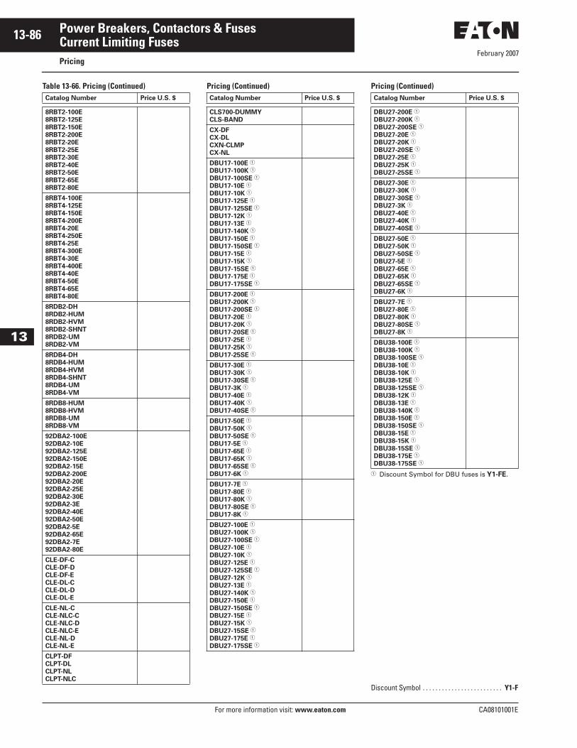
February 2007
13-86
For more information visit: www.eaton.com CA08101001E
Power Breakers, Contactors & Fuses
13
Current Limiting FusesPricing
Table 13-66. Pricing (Continued) Pricing (Continued) Pricing (Continued)
� Discount Symbol for DBU fuses is Y1-FE.
Catalog Number Price U.S. $
8RBT2-100E
8RBT2-125E
8RBT2-150E
8RBT2-200E
8RBT2-20E
8RBT2-25E
8RBT2-30E
8RBT2-40E
8RBT2-50E
8RBT2-65E
8RBT2-80E
8RBT4-100E
8RBT4-125E
8RBT4-150E
8RBT4-200E
8RBT4-20E
8RBT4-250E
8RBT4-25E
8RBT4-300E
8RBT4-30E
8RBT4-400E
8RBT4-40E
8RBT4-50E
8RBT4-65E
8RBT4-80E
8RDB2-DH
8RDB2-HUM
8RDB2-HVM
8RDB2-SHNT
8RDB2-UM
8RDB2-VM
8RDB4-DH
8RDB4-HUM
8RDB4-HVM
8RDB4-SHNT
8RDB4-UM
8RDB4-VM
8RDB8-HUM
8RDB8-HVM
8RDB8-UM
8RDB8-VM
92DBA2-100E
92DBA2-10E
92DBA2-125E
92DBA2-150E
92DBA2-15E
92DBA2-200E
92DBA2-20E
92DBA2-25E
92DBA2-30E
92DBA2-3E
92DBA2-40E
92DBA2-50E
92DBA2-5E
92DBA2-65E
92DBA2-7E
92DBA2-80E
CLE-DF-C
CLE-DF-D
CLE-DF-E
CLE-DL-C
CLE-DL-D
CLE-DL-E
CLE-NL-C
CLE-NLC-C
CLE-NLC-D
CLE-NLC-E
CLE-NL-D
CLE-NL-E
CLPT-DF
CLPT-DL
CLPT-NL
CLPT-NLC
Catalog Number Price U.S. $
CLS700-DUMMY
CLS-BAND
CX-DF
CX-DL
CXN-CLMP
CX-NL
DBU17-100E �
DBU17-100K �
DBU17-100SE �
DBU17-10E �
DBU17-10K �
DBU17-125E �
DBU17-125SE �
DBU17-12K �
DBU17-13E �
DBU17-140K �
DBU17-150E �
DBU17-150SE �
DBU17-15E �
DBU17-15K �
DBU17-15SE �
DBU17-175E �
DBU17-175SE �
DBU17-200E �
DBU17-200K �
DBU17-200SE �
DBU17-20E �
DBU17-20K �
DBU17-20SE �
DBU17-25E �
DBU17-25K �
DBU17-25SE �
DBU17-30E �
DBU17-30K �
DBU17-30SE �
DBU17-3K �
DBU17-40E �
DBU17-40K �
DBU17-40SE �
DBU17-50E �
DBU17-50K �
DBU17-50SE �
DBU17-5E �
DBU17-65E �
DBU17-65K �
DBU17-65SE �
DBU17-6K �
DBU17-7E �
DBU17-80E �
DBU17-80K �
DBU17-80SE �
DBU17-8K �
DBU27-100E �
DBU27-100K �
DBU27-100SE �
DBU27-10E �
DBU27-10K �
DBU27-125E �
DBU27-125SE �
DBU27-12K �
DBU27-13E �
DBU27-140K �
DBU27-150E �
DBU27-150SE �
DBU27-15E �
DBU27-15K �
DBU27-15SE �
DBU27-175E �
DBU27-175SE �
Catalog Number Price U.S. $
DBU27-200E �
DBU27-200K �
DBU27-200SE �
DBU27-20E �
DBU27-20K �
DBU27-20SE �
DBU27-25E �
DBU27-25K �
DBU27-25SE �
DBU27-30E �
DBU27-30K �
DBU27-30SE �
DBU27-3K �
DBU27-40E �
DBU27-40K �
DBU27-40SE �
DBU27-50E �
DBU27-50K �
DBU27-50SE �
DBU27-5E �
DBU27-65E �
DBU27-65K �
DBU27-65SE �
DBU27-6K �
DBU27-7E �
DBU27-80E �
DBU27-80K �
DBU27-80SE �
DBU27-8K �
DBU38-100E �
DBU38-100K �
DBU38-100SE �
DBU38-10E �
DBU38-10K �
DBU38-125E �
DBU38-125SE �
DBU38-12K �
DBU38-13E �
DBU38-140K �
DBU38-150E �
DBU38-150SE �
DBU38-15E �
DBU38-15K �
DBU38-15SE �
DBU38-175E �
DBU38-175SE �
Discount Symbol . . . . . . . . . . . . . . . . . . . . . . . . . Y1-F
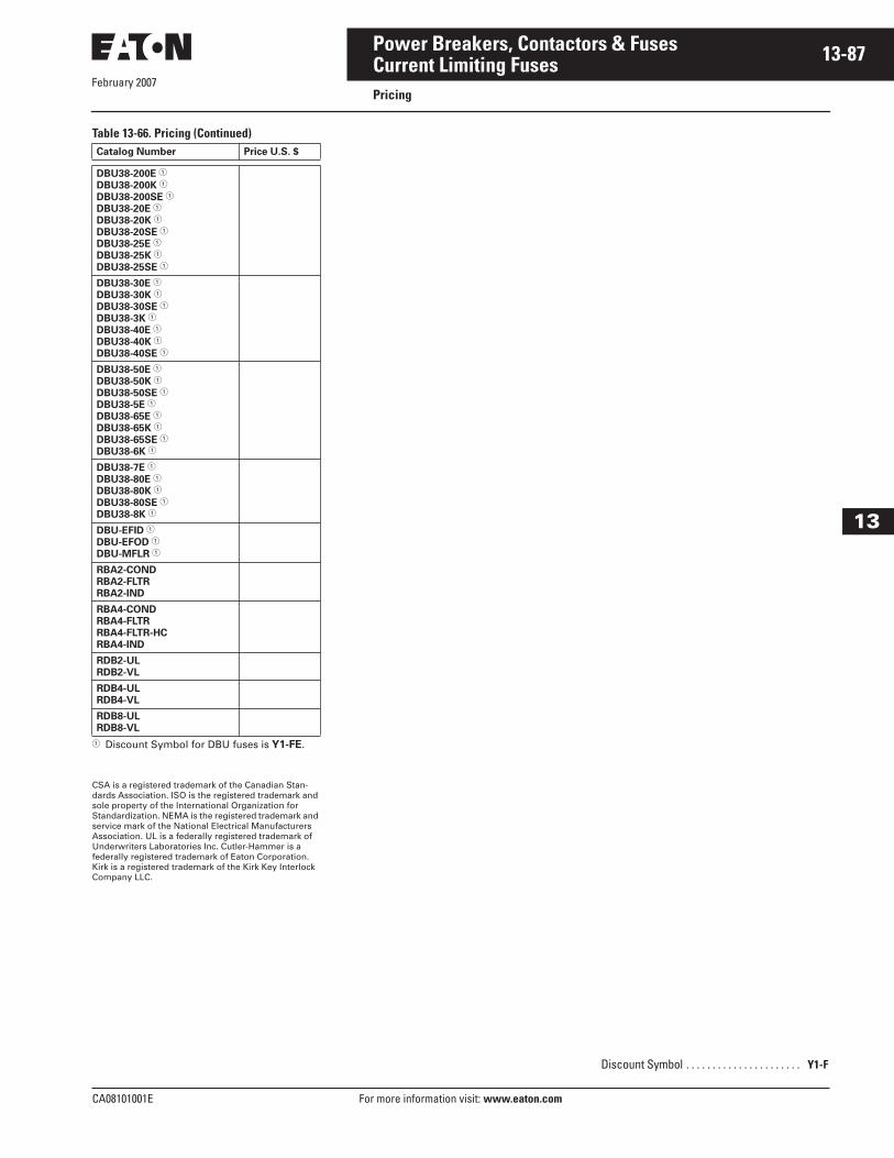
February 2007
CA08101001E For more information visit: www.eaton.com
13-87Power Breakers, Contactors & Fuses
13
Current Limiting FusesPricing
Table 13-66. Pricing (Continued)
� Discount Symbol for DBU fuses is Y1-FE.
CSA is a registered trademark of the Canadian Stan-dards Association. ISO is the registered trademark and sole property of the International Organization for Standardization. NEMA is the registered trademark and service mark of the National Electrical Manufacturers Association. UL is a federally registered trademark of Underwriters Laboratories Inc. Cutler-Hammer is a federally registered trademark of Eaton Corporation. Kirk is a registered trademark of the Kirk Key Interlock Company LLC.
Catalog Number Price U.S. $
DBU38-200E �
DBU38-200K �
DBU38-200SE �
DBU38-20E �
DBU38-20K �
DBU38-20SE �
DBU38-25E �
DBU38-25K �
DBU38-25SE �
DBU38-30E �
DBU38-30K �
DBU38-30SE �
DBU38-3K �
DBU38-40E �
DBU38-40K �
DBU38-40SE �
DBU38-50E �
DBU38-50K �
DBU38-50SE �
DBU38-5E �
DBU38-65E �
DBU38-65K �
DBU38-65SE �
DBU38-6K �
DBU38-7E �
DBU38-80E �
DBU38-80K �
DBU38-80SE �
DBU38-8K �
DBU-EFID �
DBU-EFOD �
DBU-MFLR �
RBA2-COND
RBA2-FLTR
RBA2-IND
RBA4-COND
RBA4-FLTR
RBA4-FLTR-HC
RBA4-IND
RDB2-UL
RDB2-VL
RDB4-UL
RDB4-VL
RDB8-UL
RDB8-VL
Discount Symbol . . . . . . . . . . . . . . . . . . . . . . Y1-F
February 2007
13-88
For more information visit: www.eaton.com CA08101001E
Power Breakers, Contactors & Fuses
13
This page intentionally left blank.