Embed Size (px)
Citation preview

109
SP-244—7
Modeling of Load Transfer Behavior of AR-Glass-Rovings in Textile
Reinforced Concrete
by I. Lepenies, C. Meyer, H. Schorn, and B. Zastrau
Synopsis: The failure mechanisms of textile reinforced concrete (TRC), which is a composite of bundles of long fibers and fine-grained concrete, are complex. Even after fracture of the constituents AR-glass and concrete the bond behavior has an important influence on the effective material behavior of the composite. Therefore, any realistic numerical simulation of the TRC composite behavior requires an accurate model of the bond between the reinforcement and the matrix as well as between the filaments within the roving. This paper summarizes the main characteristics of TRC. Further, an adhesive cross linkage approach is used to model the different bond aspects within the roving. In addition to this analytical approach some numerical simulations are presented.
Keywords: adhesive cross linkage; bond behavior; roving model; textile; textile reinforced concrete
110 Lepenies et al.Ingolf Lepenies is a research associate at the Technische Universität Dresden, Germany. He is a member of the Collaborative Research Centre 528 (SFB528) in Dresden. His current main research interests are textile reinforced concrete composites, hierarchical material models and multi scale methods.
Christian Meyer, FACI, is a Professor of Civil Engineering at Columbia University in the City of New York. He is chairman of ACI Committee 555, member of ACI Committee 446, Joint ACI-ASCE Committee 447, ACI Committee 544, and the ACI Board Advisory Committee on Sustainable Development. His current main research interests are fiber reinforced concrete composites and green building materials.
Harald Schorn is a Professor of Civil Engineering at the Technische Universität Dresden, Germany. He is a director of a project of the Collaborative Research Centre 528 (SFB528) in Dresden. His current main research interests are textile reinforced concrete composites, durability of fiber reinforced concrete composites and bond optimizations.
Bernd W. Zastrau is a Professor of Civil Engineering at the Technische Universität Dresden, Germany. He is a director of a project of the Collaborative Research Centre 528 (SFB528) in Dresden. His current main research interests are textile reinforced concrete composites, constitutive relations, surface-related shell theories and transient rolling contact of wheel and rail.
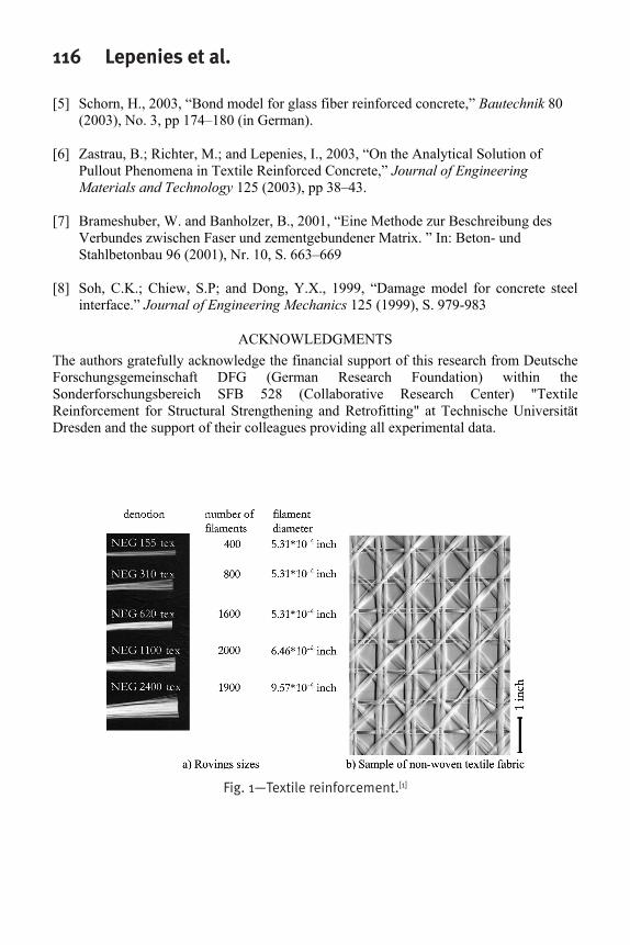
INTRODUCTION Intensive efforts are currently underway to use textile reinforced concrete (TRC) for the manufacturing of novel structural elements and the strengthening of existing structures. In contrast to concrete reinforced with randomly aligned short fibers, TRC is a composite made of continuous rovings and fine-grained concrete (aggregate size less than 1mm=0.04 in). A roving is a bundle of a large number of filaments (Fig. 1), which acts as tensile reinforcement of the brittle concrete.
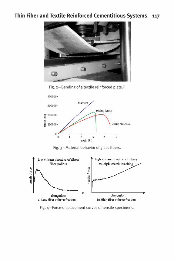
The rovings are aligned with the principal directions of the internal forces resulting from the expected load. The filaments (continuous fibers) used in this study are made of AR-glass, which is much less costly than other candidate materials like carbon. Textile fabrics can be manufactured to satisfy special requirements such as volume fraction or alignment of reinforcement (Fig. 1). In addition to increasing the stiffness the rovings enhance the ductility of the composite significantly (Fig. 2). New manufacturing methods and applications of TRC require the development and improvement of computational models.
MATERIAL BEHAVIOR OF TRC The material behavior of the AR-glass fibers is shown in Fig. 3. The filament exhibits a nearly linear elastic behavior up to fracture. The effective bundle behavior of a roving is less stiff compared with that of a single filament, because of the non-uniform stress distribution within the roving. A more ductile behavior can be observed for the textile structure.
Thin Fiber and Textile Reinforced Cementitious Systems 111Structures made of textile reinforced concrete may fail in different ways, as experiments conducted at the Collaborative Research Center “Textile Reinforcement for Structural Strengthening and Retrofitting” (SFB 528) in Dresden have shown [1]. In addition to the delamination of the TRC layer from an existing concrete structure, several failure modes of the TRC itself are possible [2]. The most important of these are:
development of microcracks accumulation of microcracks into a macrocrack debonding of fiber reinforcement from the surrounding fine-grade concrete slip between filaments within the roving and between filaments and matrix fiber fracture.
In general, the final type of failure of the composite is a combination of the different individual failure modes. Textile reinforced concrete in tension has two different types of failure, depending on the amount of fibers. In specimens with low fiber volume fractions (less than ) only one matrix crack occurs, and the composite fails by fiber fracture or pullout. Figure 4a) shows a typical force-displacement curve for this type of failure. In specimens with high fiber volume fractions (more than ) multiple matrix cracks develop prior to final rupture. After the final crack pattern has developed, the remaining stiffness of the tension specimen depends only on the stiffness of the fibers augmented by tension stiffening. A typical force-displacement curve of this type is shown in Fig. 4b). For both types of TRC the bond behaviors between roving and matrix and within the roving are decisive in determining the overall structural behaviour.
%1.0
%1
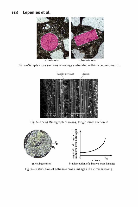
Figure 5 shows two cross sections of rovings without any textile binding embedded in fine-grained concrete. Here we want to point out the partial impregnation of the rovings and the different shapes of the roving cross sections. For a small tex value (e.g. 155 tex) the roving is nearly circular. With increasing tex value the cross sectional shape becomes more flat oval or rectangular due to manufacturing and application issues. Their bond properties are influenced by several parameters, such as fiber size, concrete mix design and age.
MOTIVATION FOR THE ADHESIVE CROSS LINKAGE APPROACH The bond behavior has been investigated using an environmental scanning electron microscope (ESEM). The micrographs obtained by Hempel et al. [3] (Fig. 6) show the discontinuous distribution of hydration products between the glass filaments which are responsible for the roving’s bond properties. These discrete regions with hydration products which provide bond between adjacent filaments shall be referred to as adhesive cross linkages [5]. The distribution of these linkages over the cross section of a roving has a decisive influence on the bond behavior of the roving. Since the roving acts like a filter for the hydrated cement particles, it can be assumed, that the number of adhesive cross linkages decreases towards the center of the roving (Fig. 7b). The strengths of these cross linkages themselves are subject to statistical scatter.
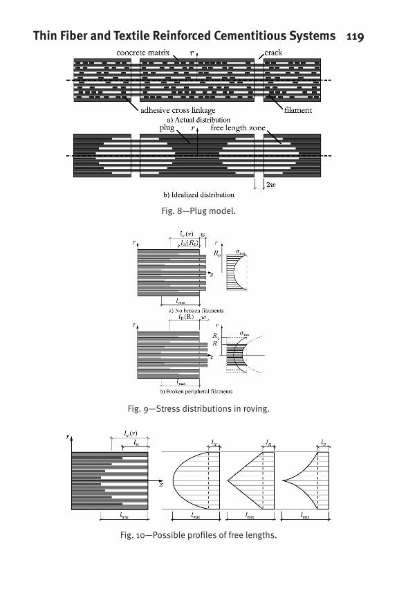
To model the adhesive cross linkages, their actual random distribution (Fig. 8a) is
112 Lepenies et al.idealized by lumping them together into a continuous “plug”, leaving a “free length” without any bond (Fig. 8b). Individual filaments are thus restrained according to their relative positions within the roving.
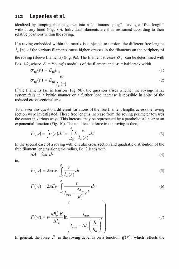
If a roving embedded within the matrix is subjected to tension, the different free lengths of the various filaments cause higher stresses in the filaments on the periphery of
the roving (sleeve filaments) (Fig. 9a). The filament stresses
)(rlw
fil can be determined with Eqs. 1-2, where E = Young’s modulus of the filament and = half crack width. w
filfilfil )( Er (1)
)()( filfil rl
wErw
(2)
If the filaments fail in tension (Fig. 9b), the question arises whether the roving-matrix system fails in a brittle manner or a further load increase is possible in spite of the reduced cross sectional area.
To answer this question, different variations of the free filament lengths across the roving section were investigated. These free lengths increase from the roving perimeter towards the center in various ways. This increase may be represented by a parabolic, a linear or an exponential function (Fig. 10). The total tensile force in the roving is then,
dArl
wEdArwFw
R
r )()()(
0
(3)
In the special case of a roving with circular cross section and quadratic distribution of the free filament lengths along the radius, Eq. 3 leads with
drrdA 2 (4) to,
drrl
rEwwFw
R
r )(2)(
0
(5)
drr
Rl
l
rEwwFw
R
r 220
max0
2)( (6)
2
0max
max20 ln)(
RRll
ll
ERwwF
ww
(7)
In general, the force F in the roving depends on a function , which reflects the )(rg
Thin Fiber and Textile Reinforced Cementitious Systems 113
assumed profile of the free lengths over the relative position r within the roving and the cross sectional shape of the roving,
)(rlw
)(
)(
0 rgdrcF
wr
i (8)
Introducing the failure strain F of a filament it is possible to establish a relationship between crack width and the partially effective roving with residual radius w R ,
FRFw RlRRllRw )()(
2
0max (9)
The roving force F is then a function of this residual radius R ,
FRRw
RlRl
ll
RERF )()(
ln)( max20 (10)
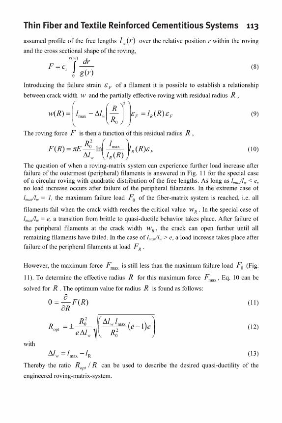
The question of when a roving-matrix system can experience further load increase after failure of the outermost (peripheral) filaments is answered in Fig. 11 for the special case of a circular roving with quadratic distribution of the free lengths. As long as lmax/lw < e,no load increase occurs after failure of the peripheral filaments. In the extreme case of lmax/lw = 1, the maximum failure load of the fiber-matrix system is reached, i.e. all
filaments fail when the crack width reaches the critical value . In the special case of l
0F
Rwmax/lw = e, a transition from brittle to quasi-ductile behavior takes place. After failure of
the peripheral filaments at the crack width , the crack can open further until all remaining filaments have failed. In the case of l
Rwmax/lw > e, a load increase takes place after
failure of the peripheral filaments at load .RF
However, the maximum force is still less than the maximum failure load (Fig.
11). To determine the effective radius maxF 0F
R for this maximum force , Eq. 10 can be
solved for maxF
R . The optimum value for radius R is found as follows:
)(0 RFR
(11)
eeR
llle
RR w
w
120
max20
opt (12)
with
Rmax lllw (13)
Thereby the ratio can be used to describe the desired quasi-ductility of the engineered roving-matrix-system.
RRopt /

114 Lepenies et al.
The roving force F relative to the force at first cracking is shown in Fig. 12a as
function of the relative crack opening . The more non-uniform load distribution
within the roving at increasing ratio reduces the force necessary to break the peripheral filaments and the maximum roving force, Fig. 12b.
RF
0/ ww
wll /max
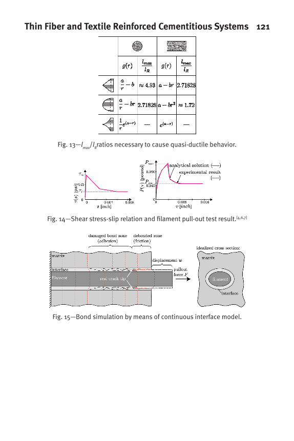
Figure 13 summarizes the ratios necessary to cause quasi-ductile behavior for circular roving sections and rectangular ones with sides a and b (Fig. 5b). It is noteworthy that for an exponential distribution of the free lengths no load increase is possible after failure of the peripheral filaments.
Rll /max
In addition to the analytical approach some numerical simulations were conducted to verify the chosen assumption. The used numerical models differ in the bond description for the roving-matrix system. Beside a continuous bond model with smeared (effective) interface parameter a discontinuous bond model with randomly distributed adhesive cross linkages will be presented.
CONTINUOUS DESCRIPTION OF BOND The continuous interface model considers the discrete adhesive cross linkages in a smeared sense by means of an interface layer with effective material parameters (Fig. 14). This model has been extensively studied during the past decades, see e.g. Soh et al.[8]
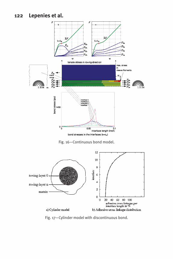
Here the focus lies on the analytical determined multi-linear bond laws between the modeled layers of the roving. Figure 16 shows a roving of circular section that was modeled with four layers of filaments. Point b is situated at the midpoint between two cracks, and point a at the macrocrack, where the roving is loaded, i.e. where it bridges the crack.
The relationship between load and crack opening has three distinct regions. The first region corresponds to the undamaged state. Subsequent loading causes damage and failure of the interface between the matrix and the outermost (peripheral) layer of filaments.
For the example configuration a linear decrease of bond strength across the roving section was assumed. This bond strength was modeled with a multi-linear bond-slip relationship by Richter [4] and Zastrau et al [6] (Fig. 14a, 15), based on pull-out experiments [7] (Fig. 14b).
After complete separation of the interface 4, the roving is loaded up to failure. In this example, the interfaces 1 to 3 do not fail.
DISCONTINUOUS DESCRIPTION OF BOND Aside from the continuous bond representation also discontinuous bond models were investigated. Again, the roving was idealised by a number of layers (Fig. 17a). The adhesive cross linkages were represented by elastic bond elements with a specific failure threshold. Assuming the closest possible packing of filaments within a roving of circular

Thin Fiber and Textile Reinforced Cementitious Systems 115
section, a roving of about (397 filaments) will contain 12 discrete layers. tex155
The computed roving stresses at the crack center depend on the distribution of the adhesive cross linkages. The relative share of linkages in each interface is depicted in Fig. 18. For example, 90% of the interface between the matrix and outermost layer of filaments contain adhesive cross linkages, whereas only 20% of the innermost interface is covered with such linkages.
In Fig. 18, the stress distributions in a roving-matrix system are shown for several realizations of random distributions of the adhesive cross linkages. Since the stresses are inversely proportional to the free length parameter,
wlr 1)( (15)
it is possible to compute the free lengths within the roving for each such random realization. For a given profile free length across the roving the free lengths vary approximately parabolically, Fig. 19a. The resulting statistical distribution of the
calculated maximum free length
wl
lmax for r/Ro = 0 is illustrated in Fig. 19b.
SUMMARY The combination of a number of individual failure mechanisms complicates the material behavior of textile reinforced concrete. The bond between the fibers and the matrix has a considerable influence on this material behavior and is very difficult to model, because of the non-uniform stress distribution over a roving section. This paper presents a model to simulate the effect of the discrete hydration products found between individual filaments (adhesive cross linkages). This model is capable of distinguishing between brittle and quasi-ductile roving failure, depending on the extent of hydration product impregnation within a roving. The validity of the various assumptions for this model was confirmed with finite element analyses using either continuous or discontinuous bond models.
REFERENCES[1] Curbach, M., ed., 2002, “SFB 528 – Textile reinforcement for strengthening and
repair,” Project SFB 528, Progress Report for Period 1999 – 2002, Technische Universität Dresden, 2001 (in German).
[2] Hegger, J., ed., 2001, “Textile reinforced concrete,” Proceedings, Projects 528 and 532 Colloquium, RWTH Aachen (in German).
[3] Hempel, R.; Schorn, H.; Schiekel, M.; and Butler, M., 2005, “Durability of Textile Reinforced Concrete,” ACI Materials Journal 4/2005.
[4] Richter, M., 2005, “Development of mechanical models to describe material properties of textile reinforced fine-grained concrete,” PhD Thesis, Technische Universität Dresden, 2005 (in German).
116 Lepenies et al.
[5] Schorn, H., 2003, “Bond model for glass fiber reinforced concrete,” Bautechnik 80 (2003), No. 3, pp 174–180 (in German).
[6] Zastrau, B.; Richter, M.; and Lepenies, I., 2003, “On the Analytical Solution of Pullout Phenomena in Textile Reinforced Concrete,” Journal of Engineering Materials and Technology 125 (2003), pp 38–43.
[7] Brameshuber, W. and Banholzer, B., 2001, “Eine Methode zur Beschreibung des Verbundes zwischen Faser und zementgebundener Matrix. ” In: Beton- und Stahlbetonbau 96 (2001), Nr. 10, S. 663–669
[8] Soh, C.K.; Chiew, S.P; and Dong, Y.X., 1999, “Damage model for concrete steel interface.” Journal of Engineering Mechanics 125 (1999), S. 979-983
ACKNOWLEDGMENTS The authors gratefully acknowledge the financial support of this research from Deutsche Forschungsgemeinschaft DFG (German Research Foundation) within the Sonderforschungsbereich SFB 528 (Collaborative Research Center) "Textile Reinforcement for Structural Strengthening and Retrofitting" at Technische Universität Dresden and the support of their colleagues providing all experimental data.
Fig. 1—Textile reinforcement.[1]
Thin Fiber and Textile Reinforced Cementitious Systems 117
Fig. 2—Bending of a textile reinforced plate.[1]
Fig. 3—Material behavior of glass fibers.
Fig. 4—Force-displacement curves of tensile specimens.
118 Lepenies et al.
Fig. 5—Sample cross sections of rovings embedded within a cement matrix.
Fig. 6—ESEM Micrograph of roving, longitudinal section.[3]
Fig. 7—Distribution of adhesive cross linkages in a circular roving.
Thin Fiber and Textile Reinforced Cementitious Systems 119
Fig. 8—Plug model.
Fig. 9—Stress distributions in roving.
Fig. 10—Possible profiles of free lengths.

120 Lepenies et al.
Fig. 11—Roving force versus crack width (circular section, parabolic free length profile).
Fig. 12—Related force dependency.
Thin Fiber and Textile Reinforced Cementitious Systems 121
Fig. 13—lmax
/lRratios necessary to cause quasi-ductile behavior.
Fig. 14—Shear stress-slip relation and filament pull-out test result.[4,6,7]
Fig. 15—Bond simulation by means of continuous interface model.
122 Lepenies et al.
Fig. 16—Continuous bond model.
Fig. 17—Cylinder model with discontinuous bond.

Thin Fiber and Textile Reinforced Cementitious Systems 123
Fig. 18—Filament stresses in model with discontinuous bond.
Fig. 19—Statistical evaluation.
124 Lepenies et al.


![Performance and Durability Evaluation of Bamboo Reinforced ... · ... bamboo reinforced beam [4]. Bamboo reinforced concrete design is similar to steel reinforced concrete design](https://img.pdfslide.us/doc/110x75/5b573ef17f8b9adf7d8d8ed2/performance-and-durability-evaluation-of-bamboo-reinforced-bamboo-reinforced.jpg)