Embed Size (px)
Citation preview
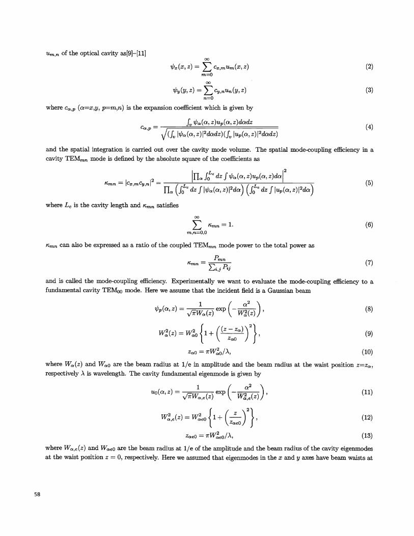
Modeling of efficient mode matching and thermal-lensing effecton a laser-beam coupling into a mode-cleaner cavity
N. Uehara, E. K. Gustafson, M. M. Fejer, and R. L. Byer'
Edward L. Ginzton Laboratory, Stanford University, Stanford, CA 94305-4085
ABSTRACT
We describe the spatial mode-matching of a diode—pumped Nd:YAG laser to a ring mode—cleaner cavity with anefficiency as high as 99.8 %. Spatial-mode coupling including thermal-lensing effects in the cavity are analyzed.
Keywords: mode matching, optical cavity, thermal-lensing effect, gravitational wave detection.
1. INTRODUCTION
Advanced interferometric gravitational wave detectors will use a 100 watt cw single-frequency laser at 1 im toimprove the detection sensitivity at high frequencies[1}—{3}. To maximize the interferometric contrast, a diffraction-limited beam is required. The optical beam transmitted by an optical cavity on resonance is both spectrally filteredand temporally ifitered. This mode-cleaner cavity consists of a high finesse Fabry-Perot interferometer and is usedimmediately after the laser source to achieve the satial mode quality and the reduction in intensity noise demandedby the gravitational wave interferometers. To develop a high transmission and high finesse mode-cleaner cavity, it isessential to use lowloss and high reflectance mirrors. These mirrors made by ion-beam sputtering, have an optical lossthat is less than 100 ppm (0.01 %) compared with 200 ppm or more loss from a standard commercial mirror made byelectron-beam evaporation. The lowest loss mirror at 1 pm reported to date has a total loss of 6 ppm[4]. In the futurethermal effects in the mode-cleaner cavity wifi become important, as the incident laserpower is increased[5}—[8}. Thecavity internal power will exceed 100 kW and mirror distortion due to absorption (1 ppm) at the high-reflectance(HR) coating will reduce the laser-beam coupling and transmission efficiency of the cavity.
In this paper, we describe efficient spatial-mode coupling as high as 99.8 % to a ring mode-cleaner cavity, andcalculate thermal-lensing effects on the mirror substrate. In section 2, mode-coupling efficiency is defined. In section3, the thermal-lensing effects associated with surface heating on the HR coating multilayers are used to calculatethe mode-coupling efficiency and phase front distortion in the transmitted beam. The experimentalsetup and themode-coupling experiment are discussed in the sections 4 and 5, respectively and in section 6, the paper is summarized.
2. DEFINITION OF MODE-COUPLING EFFICIENCY
Assume an electric field incident on an optical cavity in (x, y, z) coordinates;
'I'(x,y,z) = (1)
where the electric field is expressed as a product of the amplitudes of horizontal (x) and vertical (y) directions. Theincident electric field W(r) can be expressed as a normal-mode expansion using the Herinite-Gaussian eigenmodes
'Further author information:N.U.(correspondance): E-mail: uehara©loki.sta.nford.edu or noboru.ueharamsn.comE.K.G.: E-mail: gustaf.eestanford.eduM.M.F.: E-mail: fejer©ee.stanford.eduR.L.B.: E-mail: byer©eestanford.edu
SPIE Vol. 2989 • 0277-786X197/$1O.OO
58
Um,n of the optical cavity as[91—[11]
(x,z)= Cx,mUm(X,Z) (2)m=O
y(y, z) = ,nUn(y,z) (3)
where Ca,p (aX,y, p=m,n) is the expansion coefficient which is given by
— f(,z)up(,z)dadz(4)c,p — (f I(a,z)I2dz)(f Iup(a,z)I2dadz)
and the spatial integration is carried out over the cavity mode volume. The spatial mode-coupling efficiency in acavity TEMmn mode is defined by the absolute square of the coefficients as
2 IL fLC dzf b(a, z)u(a, z)da1Smn fCx,mCy,n = (5)
fla (jLc dzffL(a, z)I2da) (f dz f Up(, z)I2da)
where L is the cavity length and satisfies
: (6)rn,n=O,O
Kmn C1fl also be expressed as a ratio of the coupled TEMmn mode power to the total power as
mnD (7)
l_Ji,j 1ij
and is called the mode-coupling efficiency. Experimentally we want to evaluate the mode—coupling efficiency to afundamental cavity TEMCJO mode. Here we assume that the incident field is a Gaussian beam
z) = W(z) exp (- W(z)) ' (8)
W(z) = W01 +((z _z))21 '
(9)I,.
ZOJ
zaO = (10)
where W(z) and W(o are the beam radius at l/e in amplitude and the beam radius at the waist position z=z,respectively A is wavelenglh. The cavity fundamental eigenmode is given by
UO(a,Z) =W,e(Z)e (-(Z))' (11)
W,e(Z) = WeO1 + ()1, (12)j
ZaeO = 1tWe0IA, (13)
where Wo,e(Z) and Wae0 are the beam radius at l/e of the amplitude and the beam radius of the cavity eigenmodesat the waist position z = 0, respectively. Here we assumed that eigenmodes in the x and y axes have beam waists at
1 °
1O1
102
ioi-1
1 06io 100
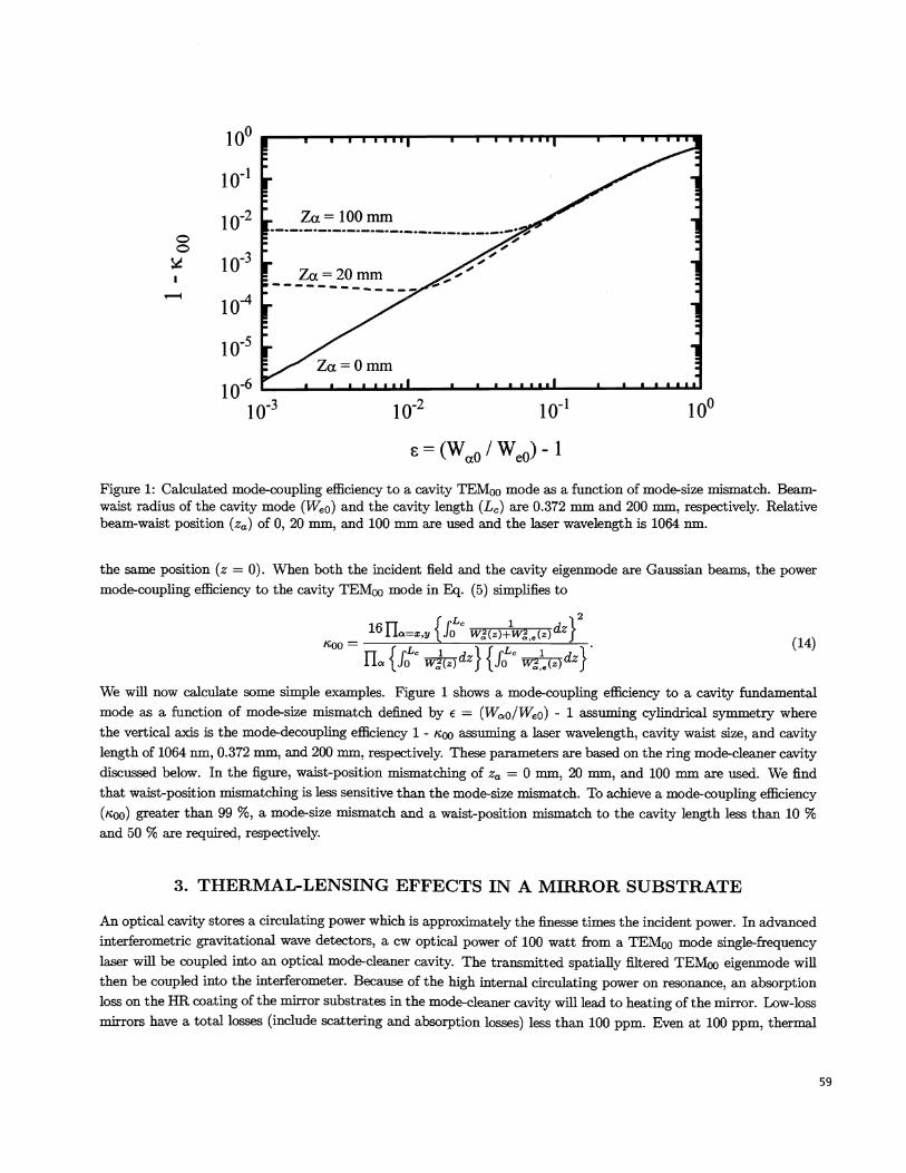
Figure 1: Calculated mode-coupling efficiency to a cavity TEM00 mode as a function of mode-size mismatch. Beam-waist radius of the cavity mode (Woo) and the cavity length (La) are 0.372 mm and 200 mm, respectively. Relativebeam-waist position (Za) of 0, 20 mm, and 100 mm are used and the laser wavelength is 1064 nm.
the same position (z = 0). When both the incident field and the cavity eigenmode are Gaussian beams, the power
mode-coupling efficiency to the cavity TEMOO mode in Eq. (5) simplifies to
16fl, {jc W(Z)±,e(Z)dZ}'too = . (14)TT IrLc 1 iIJrLc 1 _i
I1clJo iJT()U)ZfSj0 W,e(z)We wifi now calculate some simple examples. Figure 1 shows a mode-coupling efficiency to a cavity fundamentalmode as a function of mode-size mismatch defined by c = (Wa0/Weü) 1 assuming cylindrical symmetry wherethe vertical axis is the mode-decoupling efficiency 1 - , assuming a laser wavelength, cavity waist size, and cavitylength of 1064 iim, 0.372 mm, and 200 mm, respectively. These parameters are based on the ring mode-cleaner cavitydiscussed below. In the figure, waist-position mismatching of Za 0 113111, 20 Ifllfl, and 100 mm are used. We findthat waist-position mismatching is less sensitive than the mode-size mismatch. To achieve a mode-coupling efficiency('coo) greater than 99 %, a mode-size mismatch and a waist-position mismatch to the cavity length less than 10 %and 50 % are required, respectively.
3. THERMAL-LENSING EFFECTS IN A MIRROR SUBSTRATE
An optical cavity stores a circulating power which is approximately the finesse times the incident power. In advancedinterferometric gravitational wave detectors, a cw optical power of 100 watt from a TEM mode single-frequencylaser wifi be coupled into an optical mode-cleaner cavity. The transmitted spatially filtered TEMoo eigenmode willthen be coupled into the interferometer. Because of the high internal circulating power on resonance, an absorptionloss on the HR coating of the mirror substrates in the mode-cleaner cavity wifi lead to heating of the mirror. Low-lossmirrors have a total losses (include scattering and absorption losses) less than 100 ppm. Even at 100 ppm, thermal
59
102 10c = (W0 / We0) -1
4
N3
2
1—
A
F-V
Fitting function:<1(r)> = T0 b2 / (r2 + b2)
T0=3.7K,b=O.35mm
(a)
I i I00.0 0.2 0.4 0.6 0.8 1.0
(b) r [mm]
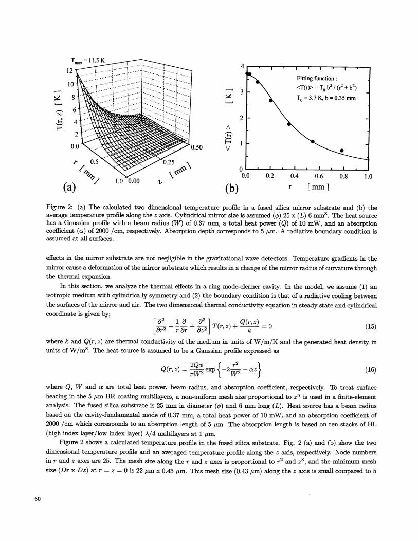
Figure 2: (a) The calculated two dimensional temperature proffle in a fused sifica mirror substrate and (b) theaverage temperature proffle along the z axis. Cylindrical mirror size is assumed () 25 x (L) 6 mm. The heat sourcehas a Gaussian proffle with a beam radius (W) of 0.37 mm, a total heat power (Q) of 10 mW, and an absorptioncoefficient (a) of 2000 /cm, respectively. Absorption depth corresponds to 5 tm. A radiative boundary condition isassumed at all surfaces.
effects in the mirror substrate are not negligible in the gravitational wave detectors. Temperature gradients in themirror cause a deformation of the mirror substrate which results in a change of the mirror radius of curvature throughthe thermal expansion.
In this section, we analyze the thermal effects in a ring mode-cleaner cavity. In the model, we assume (1) anisotropic medium with cylindrically symmetry and (2) the boundary condition is that of a radiative cooling betweenthe surfaces of the mirror and air. The two dimensional thermal conductivity equation in steady state and cylindricalcoordinate is given by;
(15)
where k and Q(r, z) are thermal conductivity of the medium in units of W/m/K and the generated heat density inunits of W/m3. The heat source is assumed to be a Gaussian proffie expressed as
Q(r,z) = exp{_2 _az} (16)
where Q, W and a are total heat power, beam radius, and absorption coefficient, respectively. To treat surfaceheating in the 5 im HR coating multilayers, a non-uniform mesh size proportional to z is used in a finite-elementanalysis. The fused silica substrate is 25 mm in diameter (çb) and 6 mm long (L). Heat source has a beam radiusbased on the cavity-fundamental mode of 0.37 mm, a total heat power of 10 mW, and an absorption coefficient of2000 /cm which corresponds to an absorption length of 5 The absorption length is based on ten stacks of HL(high index layer/low index layer) A/4 multilayers at 1 pm.
Figure 2 shows a calculated temperature profile in the fused sifica substrate. Fig. 2 (a) and (b) show the twodimensional temperature profile and an averaged temperature proffie along the Zaxis, respectively. Node numbersin r and Z axes are 25. The mesh size along the r and Z axes is proportional to r2 and Z3, and the minimum meshsize (Dr x DZ) at r = Z = 0 is 22 pm x 0.43 pm. This mesh size (0.43 pm) along the Z axis is small compared to 5
60
14 I ••' • •12 —----Calculated
- Fitting10-
's>. Fitting function:8 -
%%%%
z(r) =z0
- r2/(2R)
6 - %% R=+6mt\ 'I %%• @Q=lOmW4.
2 •I"
0 ' p ". I I i I .
0.0 0.2 0.4 0.6 0.8 1.0
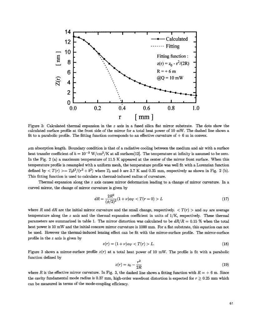
r [mm]Figure 3: Calculated thermal expansion in the z axis in a fused sifica flat mirror substrate. The dots show thecalculated surface proffle at the front side of the mirror for a total heat power of 10 mW. The dashed line shows afit to a parabolic proffle. The fitting function corresponds to an effective curvature of + 6 m in convex.
,um absorption length. Boundary condition is that of a radiative cooling between the medium and air with a surfaceheat transfer coefficient of h = iO W/cm2/K at all surfaces[12]. The temperature at infinity is assumed to be zero.In the Fig. 2 (a) a maximum temperature of 11.5 K appeared at the center of the mirror front surface. When thistemperature proffle is resampled with a uniform mesh, the temperature proffle was well fit with a Lorenzian functiondefined by < T(r) >= T0b2/(r2 + b2) where T0 and b are 3.7 K and 0.35 mm, respectively as shown in Fig. 2 (b).This fitting function is used to calculate a thermal-induced radius of curvature.
Thermal expansion along the z axis causes mirror deformation leading to a change of mirror curvature. In acurved mirror, the change of mirror curvature is given by
dR= (/)2(1+v)aT<T(r=O)>L (17)
where R and dR are the initial mirror curvature and the small change, respectively. < T(r) > and aT are averagetemperature along the z axis and the thermal expansion coefficient in units of 1/K, respectively. These thermalparameters are summarized in table 1. The mirror distortion was calculated to be dR/R =0.15 % when the totalheat power is 10 mW and the initial concave mirror curvature is 1000 mm. For a fiat substrate, this equation can notbe used. However the thermal-induced lensing effect can be fit with the mirror-surface proffie. The mirror-surfaceprofile in the z axis is given by
z(r) = (1 + u)aT < T(r) > L. (18)
Figure 3 shows a mirror-surface profile z(r) at a total heat power of 10 mW. The proffle is fit with a parabolicfunction defined by
z(r) = ZO — (19)
where R is the effective mirror curvature. In Fig. 3, the dashed line shows a fitting function with R = + 6 m. Sincethe cavity fundamental mode radius is 0.37 mm, high-order wavefront distortion is expected for r � 0.25 mm whichcan be measured in terms of the mode-coupling efficiency.
61
Mlflat
M2flat
The wavefront of the transmitted beam from the cavity is distorded by thermal-induced optical-path difference(OPD) in the output mirror. Optical-path difference between r = 0 and r = oo for a single path is given by
Idn 1OPD = + (n — 1)(1 + v)cTj <T(0) >L (20)
where n, dn/dT, and v are the refractive index of the medium, the linear temperature coefficient, and the Poisson'sratio.
3.1. THERMAL-LENSING EFFECTSIN THE RING MODE-CLEANER CAVITY
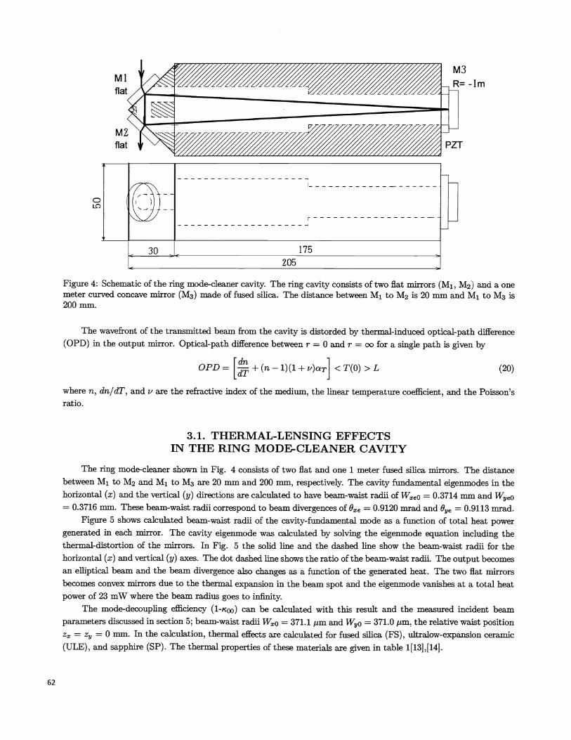
The ring mode-cleaner shown in Fig. 4 consists of two flat and one 1 meter fused silica mirrors. The distancebetween M1 to M2 and M1 to M3 are 20 mm and 200 mm, respectively. The cavity fundamental eigenmodes in thehorizontal (x) and the vertical (y) directions are calculated to have beam-waist radii of Wxe0 0.3714 111111 and W,e0= 0.3716 mm. These beam-waist radii correspond to beam divergences of 92 =0.9120 mrad and 0ye 0.9113 imd.
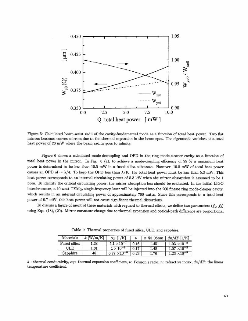
Figure 5 shows calculated beam-waist radii of the cavity-fundamental mode as a function of total heat powergenerated in each mirror. The cavity eigenmode was calculated by solving the eigenmode equation including thethermal-distortion of the mirrors. In Fig. 5 the solid line and the dashed line show the beam-waist radii for thehorizontal (x) and vertical (y) axes. The dot dashed line shows the ratio of the beam-waist radii. The output becomesan effiptical beam and the beam divergence also changes as a function of the generated heat. The two flat mirrorsbecomes convex mirrors due to the thermal expansion in the beam spot and the eigenmode vanishes at a total heatpower of 23 mW where the beam radius goes to infinity.
The mode-decoupling efficiency (l-icoo) can be calculated with this result and the measured incident beamparameters discussed in section 5; beam-waist radii Wo =371.1 m and W0 = 371.0 1um, the relative waist positionz1, = = 0 mm. In the calculation, thermal effects are calculated for fused sifica (FS), ultralow-expansion ceramic(ULE), and sapphire (SP). The thermal properties of these materials are given in table 1[13],[14].
M3
R= -im
PZT
Figure 4: Schematic of the ring mode-cleaner cavity. The ring cavity consists of two flat mirrors (M1 , M2) and a onemeter curved concave mirror (M3) made of fused silica. The distance between M1 to M2 is 20 mm and M1 to M3 is200 mm.
62
1.05
1.00
2 0.95
0.375
0.350 0.900.0 10.0
Figure 5: Calculated beam-waist radii of the cavity-fundamental mode as a function of total heat power. Two flatmirrors becomes convex mirrors due to the thermal expansion in the beam spot. The eigenmode vanishes at a totalheat power of 23 mW where the beam radius goes to infinity.
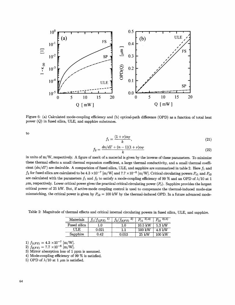
Figure 6 shows a calculated mode-decoupling and OPD in the ring mode-cleaner cavity as a function oftotal heat power in the mirror. In Fig. 6 (a), to achieve a mode-coupling efficiency of 99 % a maximum heatpower is determined to be less than 10.5 mW in a fused silica substrate. However, 10.5 mW of total heat powercauses an OPD of A/4. To keep the OPD less than A/lU, the total heat power must be less than 5.3 mW. Thisheat power corresponds to an internal circulating power of 5.3 kW when the mirror absorption is assumed to be 1ppm. To identify the critical circulating power, the mirror absorption loss should be evaluated. In the initial LIGOinterferometer, a 10 watt TEMoo single-frequency laser will be injected into the 200 finesse ring mode-cleaner cavity,which results in an internal circulating power of approximately 700 watts. Since this corresponds to a total heatpower of 0.7 mW, this heat power wifi not cause significant thermal distortions.
To discuss a figure of merit of these materials with reguard to thermal effects, we define two parameters (fi ,12)using Eqs. (18), (20). Mirror curvature change due to thermal expansion and optical-path difference are proportional
Table 1: Thermal properties of fused silica, ULE, and sapphire.
Materiais k [W/m/K] I c [1/K] I I n dn/dT [1/K]Fused silica 1.38 5.1 x10 0.16 1.45 1.03 x10⁵
ULE 1.31 1 x 10—8 0.17 1.48 1.07 x10⁵Sapphire 46 6.77 x10 0.23 1.76 1.23 x10⁵
k: thermal conductivity, aT: thermal expansion coefficient, v: Poisson's ratio, n: refractive index, dn/dT: the lineartemperature coefficient.
63
0.450
0.425
0.400
2.5 5.0 7.5
Q total heat power [mW]
64
C
MaterialsI fl/fl(Fs) 1) f2/f2(FS) 2) I P1 3),4) Pc2 3),5)
Fused silica 1.0 1.0 10.5 kW 5.3 kWULE 0.021 1.1 500kW 4.8kW
Sapphire 0.42 0.053 25 kW 100 kW
1) fl(Fs) = 4.3 x10⁷ [m/W}.2) f2(Fs) = 7.7 x10⁶ [m/W].3) Mirror absorption loss of 1 ppm is assumed.4) Mode-coupling efficiency of 99 % is satisfied.5) OPD of A/10 at 1 m is satisfied.
101
10.2
1
io-4
io0 5 10 15 20 0 5 10 15 20
100 0.5
0.4
i0.30.2
0.1
0.0
Q[mW] Q[mW]
Figure 6: (a) Calculated mode-coupling efficiency and (b) optical-path difference (OPD) as a function of total heatpower (Q) in fused silica, ULE, and sapphire substrates.
to(l+v)aTfl= k ' (21)
drt/dT + (n — 1)(1 + v)cTf2 k (22)
in units of m/W, respectively. A figure of merit of a material is given by the inverse of these parameters. To minimizethese thermal effects a small thermal expansion coefficient, a large thermal conductivity, and a small thermal coeffi-cient (dn/dT) are desirable. A comparision of fused sifica, ULE, and sapphire are summarized in table 2. Here ft and12 for fused silica are calculated to be 4.3 x 10 [m/W] and 7.7 x 10⁶ [m/WJ. Critical circulating powers P1 and P2are calculated with the parameters Ii and 12 to satisfy a mode-coupling efficiency of 99 % and an OPD of A/10 at 1m, respectively. Lower critical power gives the practical critical circulating power (Ps). Sapphire provides the largestcritical power of 25 kW. But, if active-mode coupling control is used to compensate the thermal-induced mode-sizemismatching, the critical power is given by P2 = 100 kW by the thermal-induced OPD. In a future advanced mode-
Table 2: Magnitude of thermal effects and critical internal circulating powers in fused sffica, ULE, and sapphire.
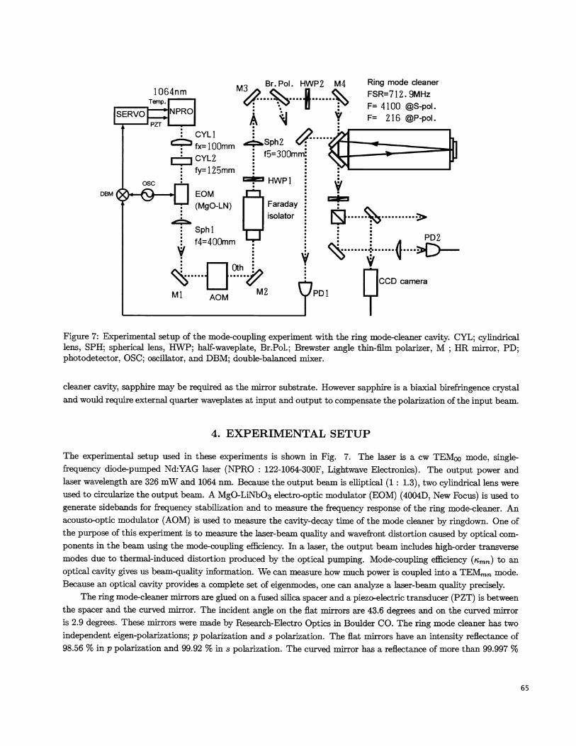
Figure 7: Experimental setup of the mode-coupling experiment with the ring mode-cleaner cavity. CYL; cylindricallens, SPH; spherical lens, HWP; haif-waveplate, Br.Pol.; Brewster angle thin-film polarizer, M ; HR mirror, PD;photodetector, OSC; oscillator, and DBM; double—balanced mixer.
cleaner cavity, sapphire may be required as the mirror substrate. However sapphire is a biaxial birefringence crystaland would require external quarter waveplates at input and output to compensate the polarization of the input beam.
4. EXPERIMENTAL SETUP
The experimental setup used in these experiments is shown in Fig. 7. The laser is a cw TEMoo mode, single—frequency diode—pumped Nd:YAG laser (NPRO : 122-1064-300F, Lightwave Electronics). The output power andlaser wavelength are 326 mW and 1064 nm. Because the output beam is effiptical (1 : 1.3), two cylindrical lens wereused to circularize the output beam. A MgO-LiNbO3 electro—optic modulator (EOM) (4004D, New Focus) is used togenerate sidebands for frequency stabilization and to measure the frequency response of the ring mode—cleaner. Anacousto-optic modulator (AOM) is used to measure the cavity-decay time of the mode cleaner by ringdown. One ofthe purpose of this experiment is to measure the laser-beam quality and wavefront distortion caused by optical com-ponents in the beam using the mode-coupling efficiency. In a laser, the output beam includes high-order transversemodes due to therxnai-induced distortion produced by the optical pumping. Mode-coupling efficiency ('cmn) to anoptical cavity gives us beam-quality information. We can measure how much power is coupled into a TEMmn mode.Because an optical cavity provides a complete set of eigenmodes, one can analyze a laser-beam quality precisely.
The ring mode-cleaner mirrors are glued on a fused silica spacer and a piezo-electric transducer (PZT) is betweenthe spacer and the curved mirror. The incident angle on the flat mirrors are 43.6 degrees and on the curved mirroris 2.9 degrees. These mirrors were made by Research-Electro Optics in Boulder CO. The ring mode cleaner has two
independent eigen-polarizations; p polarization and s polarization. The flat mirrors have an intensity reflectance of98.56 % in p polarization and 99.92 % in s polarization. The curved mirror has a reflectance of more than 99.997 %
1064nmRing mode cleanerFSR=712. 9MHzF= 4100 @S-pol.F= 216 P-pol.
DBM
Br.Pol. HWP2 M4M%A1 t_____Sph2 & __
f5=300mm: .HWP1
+Faradayisolator
Sphl :f4400mm PD2
Ml AOM M2
65
66
400
100
I
1
1
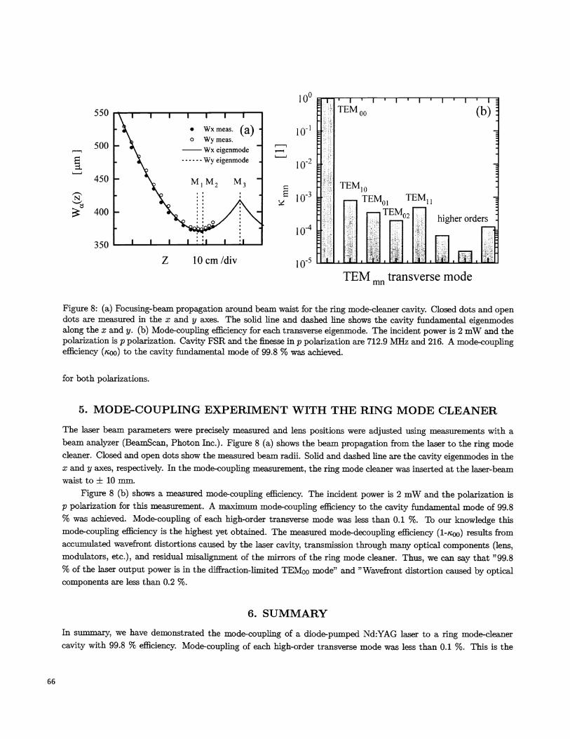
Figure 8: (a) Focusing-beam propagation around beam waist for the ring mode-cleaner cavity. Closed dots and opendots are measured in the x and y axes. The solid line and dashed line shows the cavity fundamental eigenmodesalong the x and y. (b) Mode-coupling efficiency for each transverse eigenmode. The incident power is 2 mW and thepolarization is p polarization. Cavity FSR and the finesse in p polarization are 712.9 MHz and 216. A mode-couplingefficiency ('coo) to the cavity fundamental mode of 99.8 % was achieved.
for both polarizations.
5. MODE-COUPLING EXPERIMENT WITH THE RING MODE CLEANER
The laser beam parameters were precisely measured and lens positions were adjusted using measurements with abeam analyzer (BeamScan, Photon Inc.). Figure 8 (a) shows the beam propagation from the laser to the ring modecleaner. Closed and open dots show the measured beam radii. Solid and dashed line are the cavity eigenmodes in thea; and y axes, respectively. In the mode-coupling measurement, the ring mode cleaner was inserted at the laser-beamwaist to 10 mm.
Figure 8 (b) shows a measured mode-coupling efficiency. The incident power is 2 mW and the polarization isp polarization for this measurement. A maximum mode-coupling efficiency to the cavity fundamental mode of 99.8% was achieved. Mode-coupling of each high-order transverse mode was less than 0.1 %. To our knowledge thismode-coupling efficiency is the highest yet obtained. The measured mode-decoupling efficiency (1-,coo) results fromaccumulated wavefront distortions caused by the laser cavity, transmission through many optical components (lens,modulators, etc.), and residual misalignment of the mirrors of the ring mode cleaner. Thus, we can say that "99.8% of the laser output power is in the diffraction-limited TEM00 mode" and "Wavefront distortion caused by opticalcomponents are less than 0.2 %.
6. SUMMARY
In summary, we have demonstrated the mode-coupling of a diode-pumped Nd:YAG laser to a ring mode-cleanercavity with 99.8 % efficiency. Mode-coupling of each high-order transverse mode was less than 0.1 %. This is the
550
500
450
10'
N
I 0
350
z 10cm/div
TEM mn transverse mode
highest mode-coupling yet obtained to our knowledge. High-sensitive measurements are expected in the thermal-lensing effect discussed here. Mode-decoupling due to the thermal-lensing effects on the HR coating multilayers inthe mode-cleaner cavity were calculated using a finite-element analysis in fused sifica, ULE, and sapphire substrates.The ring mode cleaner made of a fused sifica substrate can be used at up to a cavity internal power of 5.3 kW with amode-coupling efficiency of more than 99 % and an optical-path difference in the transmitted beam of less than A/1Oat 1/fm. However cylindrical symmetry was assumed in the ring mode-cleaner cavity, the elliptical beam spot onthe HR mirror will give us slightly smaller thermal-lensing effects than that discussed here. For the advanced gray-itational wave detector mode cleaner, sapphire may be required as the mirror substrate to reduce thermal distortions.
ACKNOWLEDGMENTS
We thank Stan Whitcomb and Rick Savage of the California Institute of Technology for their helpful discussions. Thiswork was supported by the National Science Foundation grant (PYS-9630172) and (PYS-9210038) under cooperativeagreement with the LIGO project.
REFERENCES
[1} K. S. Thorne, "300 Years of Gravitation," S. W. Hawking and W. Israel eds., Cambridge U. Press, Cambridge,pp. 330 - 458, 1987.
[2] A. Abramovici, W. E. Aithouse, R. W. P. Drever, Y. Giirsel, S. Kawamura, F. J. Raab, D. Shoemaker, L.Sievers, R. E. Spero, K. S. Thorne, R. E. Vogt, R. Weiss, S. E. Whitcomb, and M. E. Zucker, "LIGO: the laserinterferometer gravitational-wave observatory," Science 256, pp. 325 - 333, 1992.
[3] R. L. Byer, "GALILEO: Stanford Advanced Gravitational-Wave Laser Interferometer Program," Proposal tothe National Science Foundation, 1995 December 20.
{4} N. Uehara, A. Ueda, K. Ueda, H. Sekiguchi, T. Mitake, K. Nakamura, and N. Kitajima, and I. Kataoka,"Ultralow-loss mirror of the parts-in-106 level at 1064 nm," Opt. Lett. 20, pp. 530 - 532, 1995.
{5} P. Hello and J-Y. Vinet, "Analytical models of transient thermoelestic deformations of mirrors heated by highpower cw laser beeam," J. Phys. France 51, pp. 2243 - 2261, 1990.
[6] W. Winider, K. Danzmaim, A. Rudiger, and R. Shilling, "Heating by optical absorption and the performanceof interferometric gravitational-wave detectors," Phys. Rev. A 44, pp. 7022 -7036, 1991.
{ 7] N. Uehara and K. Ueda, "Accurate measurement of ultralow loss in a high-finesse Fabry-Perot interferometer
using the frequency response functions," Appi. Phys. B, 61, pp. 9-15, 1995.
{ 8] N. Uehara and K. Ueda, "Accurate measurement of the radius of curvature of a concave mirror and the power
dependence in a high-finesse Fabry-Perot interferometer," Appi. opt. 34, pp. 5611 - 5619, 1995.
[91 H. Kogelnik, "Coupling and conversion coefficients for optical modes," Symoisium on Quasi-Optics, pp 333 -347, 1964.
[10] A. Yariv, "Optical Electronics," 3rd edn. NY, CBS College Publishing, Chap. 4., 1985.
[11] A. E. Siegman, "Lasers," University Science, Mill Valley, CA, 1986.
67
68
[12] E. It. G. Eckert and R. M. Drake, Jr., "Analysis of Heat and Mass ftansfer," 2nd ed. New York, McGraw-Hffl,1972.
[131 R Waynant and M. Ediger, "Electro-optic handbook," chap. 11, McGraw-Hill mc, New York, 1994.
[14] Corning code 7971, Titanium sfficate, (MP-21-4, Corning, NY 14831), 1990.