Embed Size (px)
Citation preview

Modeling of DC MachinesByDr. Ungku Anisa Ungku AmirulddinDepartment of Electrical Power EngineeringCollege of Engineering
Dr. Ungku Anisa, July 2008 1EEEB443 - Control & Drives

OutlineIntroductionTheory of OperationField ExcitationSeparately Excited DC MotorState-Space ModelingBlock Diagrams and Transfer FunctionsMeasurement of Motor ConstantsReferences
Dr. Ungku Anisa, July 2008 EEEB443 - Control & Drives 2

IntroductionDC motor in service for more than a centuryDominated variable speed applications before
Power Electronics were introducedAdvantage:
Precise torque and speed control without sophisticated electronics
Dr. Ungku Anisa, July 2008 EEEB443 - Control & Drives 3

IntroductionSome limitations:
High maintenance (commutators & brushes)ExpensiveSpeed limitationsSparking
Commonly used DC motorsSeparately excitedSeries (mostly for traction applications)
Dr. Ungku Anisa, July 2008 EEEB443 - Control & Drives 4
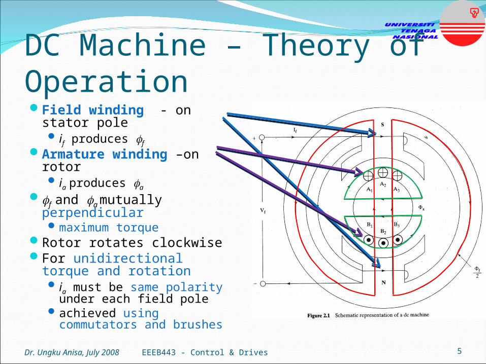
DC Machine – Theory of Operation Field winding - on stator pole
if produces f
Armature winding –on rotor ia produces a
f and a mutually perpendicularmaximum torque
Rotor rotates clockwiseFor unidirectional torque and
rotation ia must be same polarity under
each field poleachieved using commutators
and brushes
Dr. Ungku Anisa, July 2008 EEEB443 - Control & Drives 5

DC Machine – Field ExcitationDepends on connections of field winding relative to
armature windingTypes of DC machines:
Separately ExcitedShunt ExcitedSeries ExcitedCompoundedPermanent Magnet
Dr. Ungku Anisa, July 2008 EEEB443 - Control & Drives 6

DC Machine – Field ExcitationSeparately Excited
Field winding separated from armature winding Independent control of if (f ) and ia (T)
Dr. Ungku Anisa, July 2008 EEEB443 - Control & Drives 7

DC Machine – Field ExcitationShunt Excited
Field winding parallel to armature winding
Variable-voltage operation complex Coupling of f (if ) and T (ia)
productionT vs characteristic almost
constant AR = armature reaction (as T , ia , armature flux
weakens main flux f , )
Dr. Ungku Anisa, July 2008 EEEB443 - Control & Drives 8
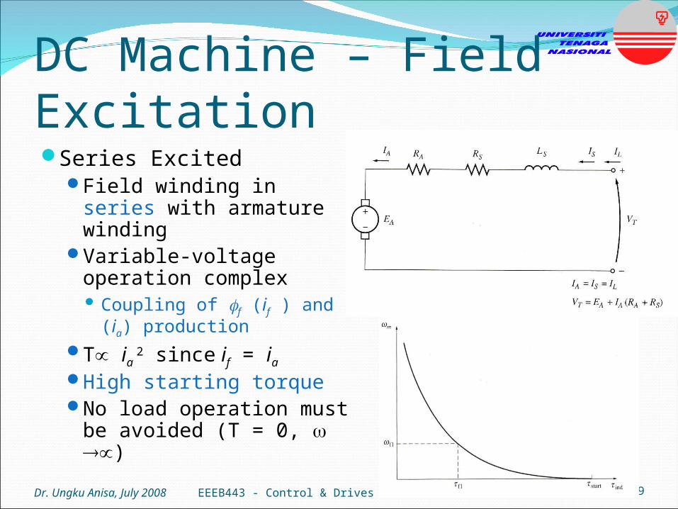
DC Machine – Field ExcitationSeries Excited
Field winding in series with armature winding
Variable-voltage operation complex Coupling of f (if ) and T (ia)
productionT ia
2 since if = ia
High starting torqueNo load operation must be
avoided (T = 0, )
Dr. Ungku Anisa, July 2008 EEEB443 - Control & Drives 9

DC Machine – Field ExcitationCompounded
Combines best feature of series and shunt Series – high starting torque Shunt – no load operation
Cumulative compounding shunt and series field
strengthens each other. Differential compounding
shunt and series field opposes each other.
Dr. Ungku Anisa, July 2008 EEEB443 - Control & Drives 10
Long-shunt connection
Short-shunt connection

DC Machine – Field ExcitationPermanent Magnet
Field provided by magnetsLess heat
No field winding resistive losses
Compact Armature similar to
separately excited machine
Disadvantages: Can’t increase flux Risk of demagnetisation
due to armature reaction
Dr. Ungku Anisa, July 2008 EEEB443 - Control & Drives 11

Lf Rf
if
aa
aaaa edt
diLiRv
+
ea
_
LaRa
ia+
vt
_
+
vf
_
Separately Excited DC Machine
Dr. Ungku Anisa, July 2008 EEEB443 - Control & Drives 12
dt
diLiRv fffff
abae iKiKT Electromagnetic torque
ba KKe Armature back e.m.f.
Armaturecircuit
Fieldcircuit

Separately Excited DC MotorMotor is connected to a
load.Therefore,
whereTL= load torque
J = load inertia (kg/m2)
B = viscous friction coefficient (Nm/rad/s)
Dr. Ungku Anisa, July 2008 EEEB443 - Control & Drives 13
Le TBdt
dJT

DC Machine - State-Space ModelingDC motor dynamic equations:
Therefore,
Dr. Ungku Anisa, July 2008 EEEB443 - Control & Drives 14
aa
aaaa edt
diLiRv
Le TBdt
dJT
a
ba
aa
a
aa
L
Kv
Li
L
R
dt
di
1
Lab T
JJ
Bi
J
K
dt
d 1
abae iKiKT
ba KKe (1) (2)
(3) (4)
(5)
(6)

DC Machine - State-Space ModelingFrom (5) and (6), the dynamic equations in state-space
form:
where s = differential operator with respect to time This can be written compactly as:
Dr. Ungku Anisa, July 2008 EEEB443 - Control & Drives 15
L
aa
a
b
a
b
a
aa
T
v
J
Li
JB
JK
LK
LR
s
si
10
01
BUAXX
(7)
(8)

DC Machine - State-Space ModelingComparing (7) and (8):
Dr. Ungku Anisa, July 2008 EEEB443 - Control & Drives 16
JB
JK
LK
LR
b
a
b
a
a
A
vector variable state ----- Tai X
vector input ----- TLa TvU
J
La10
01B

DC Machine - State-Space ModelingThe roots of the system are the eigenvalues of matrix A
1 and 2 always have negative real part, i.e. motor is stable on open-loop operation.
Dr. Ungku Anisa, July 2008 EEEB443 - Control & Drives 17
JB
JK
LK
LR
b
a
b
a
a
A
a
b
a
a
a
a
a
a
JL
K
JL
BR
J
B
L
R
J
B
L
R 22
21 42
1
2
1, (9)

DC Machine – Block Diagrams and Transfer FunctionsTaking Laplace transform of (1) and (3) and neglecting initial
conditions:
These relationships can be represented in the following block diagram
Dr. Ungku Anisa, July 2008 EEEB443 - Control & Drives 18
aa
b
LR
K
s
sωsVsI a
a
JB
Kbs
sTsIsω La
(10) (11)
aa LR s
1
JB s
1
Kb
TL(s)
Te(s)Ia(s)
Va(s)
Kb
(s)++
-
-

DC Machine – Block Diagrams and Transfer FunctionsFrom the block diagram, the following transfer functions can be derived:
Since the motor is a linear system, the speed response due to simultaneous Va input and TL disturbance is:
The Laplace inverse of (14) gives the speed time response (t).
Dr. Ungku Anisa, July 2008 EEEB443 - Control & Drives 19
22a
ωVsssV
sωsG
a
baaaa
b
KBRJRBLJL
K
(12)
(13)
22
LωT
ss
s
sT
sωsG
L
baaaa
aa
KBRJRBLJL
LR
sTsGsVsGsω LωTaωV La (14)
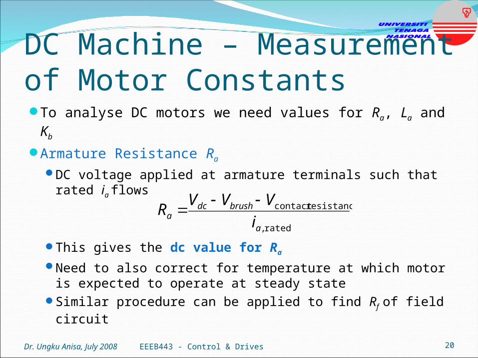
DC Machine – Measurement of Motor ConstantsTo analyse DC motors we need values for Ra, La and Kb
Armature Resistance Ra
DC voltage applied at armature terminals such that rated ia
flows
This gives the dc value for Ra
Need to also correct for temperature at which motor is expected to operate at steady state
Similar procedure can be applied to find Rf of field circuitDr. Ungku Anisa, July 2008 EEEB443 - Control & Drives 20
rated ,
resistance contact
a
brushdca i
VVVR

DC Machine – Measurement of Motor ConstantsArmature Inductance La
Apply low AC voltage through variac at armature terminals
Measure ia Motor must be at standstill
(i.e. = 0 and e = 0)
f = supply frequency in HzRa = ac armature resistanceSimilar procedure can be
applied to find Lf of field circuit
Dr. Ungku Anisa, July 2008 EEEB443 - Control & Drives 21
f
RI
V
La
a
a
a 2
2
2
(variac)

DC Machine – Measurement of Motor ConstantsEMF Constant Kb = K
Rated field voltage applied and kept constant
Shaft rotated by another dc motor up to rated speed
Voltmeter connected to armature terminals gives value of Ea
Get values of ea at different speeds
Plot Ea vs. Slope of curve = Kb Units of Kb = [V/rads-1]
Dr. Ungku Anisa, July 2008 EEEB443 - Control & Drives 22
Ea (V)
(rad/s)

ReferencesKrishnan, R., Electric Motor Drives: Modeling, Analysis and
Control, Prentice-Hall, New Jersey, 2001.Chapman, S. J., Electric Machinery Fundamentals, McGraw
Hill, New York, 2005.Nik Idris, N. R., Short Course Notes on Electrical Drives,
UNITEN/UTM, 2008.Ahmad Azli, N., Short Course Notes on Electrical Drives,
UNITEN/UTM, 2008.
Dr. Ungku Anisa, July 2008 23EEEB443 - Control & Drives