Embed Size (px)
Citation preview

Software Support: Page 1 More eHelps:[email protected] © Carrier Corporation, 2014. All rights reserved. Software Support Web Page
Modeling Heat Recovery Plants:HX in Condenser Loop
HAP e-Helprev Dec 5, 2014 HAP v4.9
Introduction
This eHelp explains how to model a heat recovery plant using a Heat Exchanger in the Condenser Water Loop. Thismodeling feature is offered in HAP v4.9 and later versions. In the “System Overview” section below the configuration andoperation of equipment in this plant is described. In the second section, a tutorial explains how to model this type of plantin HAP.
Figure 1. Diagram of Heat Recovery Plant with Heat Exchanger in Condenser Loop
(Note: This is a simplified diagram only intended to show the basic arrangement of components)
System Overview
Basics of Equipment Configuration and Operation
Figure 1 contains a simple diagram of a heat recovery plant using a heat exchanger in the condenser loop:
• The upper half of the diagram shows a hot water system with two hot water boilers in parallel and aprimary/secondary water loop providing hot water to heating coils in air handlers or fan coil units. Note that there canbe different types of of heat recovery systems. Some will supply heat to a service hot water (SHW) system instead ofor in addition to serving space heating loads.

Software Support: Page 2 More eHelps:[email protected] © Carrier Corporation, 2014. All rights reserved. Software Support Web Page
Modeling Heat Recovery Plants:HX in Condenser Loop
HAP e-Helprev Dec 5, 2014 HAP v4.9
• The lower half of the diagram shows a chilled water system with two water-cooled chillers in parallel providing chilledwater via a primary/secondary water loop to cooling coils in air handlers or fan coil units.
• In this diagram the air handler icons are shown separately for the cooling and heating loops, but typically these will besingle equipment units containing both cooling and heating coils. The air handlers are shown separately to make thediagram more readable.
• When simultaneous cooling and heating loads exist in the building and the hot water system return temperature isless than the leaving condenser water from the chillers, heat recovery is possible. The valve in the hot water returnpipe (middle left in the diagram) diverts some or all of the hot water return flow into the heat recovery pipe. The heatrecovery booster pump is activated and circulates the return water to the heat exchanger (HX). The flow of warmercondenser loop water through the HX transfers heat to the lower temperature water entering the HX from the hotwater system. The heated water then returns to the hot water loop just upstream of the boilers.
• If the heat added to the return water is sufficient to meet the heating system load, then the hot return water bypassesthe boilers (bypass leg not shown in diagram), the boilers remain off, and 100% of the demand is provided byrecovered heat. On the other hand, if the recovered heat is not sufficient to meet the full heating plant load, then oneor more of the boilers operate to satisfy the remainder of the heating demand, and heat recovery satisfies only part ofthe demand.
• Heat recovery can only occur if the condenser loop water entering the HX is warmer than the water from the heatrecovery pipe entering the HX. Therefore it is necessary to operate the chillers at condenser water temperaturesmuch higher than in conventional chiller plants.
Example: Suppose the hot water system has a design hot water supply temperature (HWST) of 140 F (60 C) and a 40F (22.2 K) delta-T. Therefore at the design condition, the return water temperature in the hot water system will be 100F (37.8 C). Assuming the design HWST is held constant, as the hot water system part-load ratio drops, the returnwater temperature will increase. Therefore the return water temperature will be 100 F at 100% load, 120 F at 50%load and 130 F at 25% load.
In order to recover heat, the condenser loop water entering the HX must be warmer than the hot water system returntemperature. So if the HW loop return water is 100 F, the condenser leaving temperature must be greater than 100 F.Suppose the design delta-T for the chiller condenser flow is 10 F. To produce 110 F condenser outlet water, thechiller entering condenser water temperature (ECWT) must be 100 F. To produce 120 F condenser outlet water, thechiller ECWT must be 110 F.
Survey of Advantages and Disadvantages
As with most heat recovery schemes, this scheme causes some costs to increase and other costs to decrease. Whenapplied to a building with good heat recovery potential, the net result can be an overall savings which justifies the system.Key issues for consideration:
• Heating energy cost will decrease. In this type of system, recovered heat is a by product of chiller cooling. As aresult recovered heat is considered “free heat”. By this convention, the heating energy cost for the building decreasesdue to heat recovery.
• Cooling energy cost will increase. As noted in the previous section, the chillers must be run at elevated enteringcondenser water temperatures (ECWT) in order to supply condenser outlet water hot enough to transfer heat to theheating system. Chillers are less efficient when operating at high ECWT than at low ECWT. Therefore, the chillers in

Software Support: Page 3 More eHelps:[email protected] © Carrier Corporation, 2014. All rights reserved. Software Support Web Page
Modeling Heat Recovery Plants:HX in Condenser Loop
HAP e-Helprev Dec 5, 2014 HAP v4.9
this type of heat recovery system typically use more energy than chillers in a conventional cooling plant wherecondenser temperatures are much lower.
• Cooling tower fan energy cost may decrease. Because this heat recovery system typically holds ECWT atelevated levels, less heat rejection through the cooling tower (or dry cooler) is required. In addition transfer of heat tothe hot water system reduces the total amount of heat to be rejected by the cooling tower. This can allow more hoursof modulated cooling tower fan operation, either by fan cycling, 2-speed fan operation or variable speed operation.That will reduce cooling tower fan energy cost. In a conventional chiller plant where the control often is attempting tominimize ECWT to gain increased chiller efficiency, the cooling tower fans will run at full speed for more hours andconsume more energy.
Example: The ECWT is held at 120 F (48.9 C) in order to provide high temperature condenser leaving water to theheat exchanger. For off-design hours the cooling tower has excess heat rejection capacity and can produce 120 Fleaving water without running the tower fan at full speed. Therefore it is able to use fan cycling, 2-speed fan control orvariable speed fan control to reduce fan energy use at these times.
• Overall energy cost savings will depend on the sizes of the heating energy cost savings, cooling tower fan energycost savings and chiller energy cost increase. In a building with good heat recovery potential and with a well-designed heat recovery system, a net energy cost savings can result.
Figure 2. Building with Good Heat Recovery Potential
• First cost will typically increase. High performance HVAC systems often involve a tradeoff between increased firstcost for additional components and controls in exchange for lower energy costs. The lower energy costs ultimatelypays back the increased first cost and deliver net savings over the life of the system. This heat recovery system is noexception. This type of heat recovery system requires additional pumps, piping, a heat exchanger and controls. To

Software Support: Page 4 More eHelps:[email protected] © Carrier Corporation, 2014. All rights reserved. Software Support Web Page
Modeling Heat Recovery Plants:HX in Condenser Loop
HAP e-Helprev Dec 5, 2014 HAP v4.9
operate at high ECWT levels may also require more expensive components for the chillers. Therefore, the purchaseand installation cost for this heat recovery plant will generally be higher than for a conventional plant.
• Lifecycle cost may decrease. While first cost will be higher for heat recovery, in a building with good heat recoverypotential and a well-designed system, energy costs can be lower. This will deliver payback and net savings over thelife of the system.
Keys to Successful Application
Successful application of a heat recovery plant first requires a building with simultaneous cooling and heating loads for asignificant number of hours per year. Examples of buildings that may have good heat recovery potential include hotels,dormitories and hospitals. Each of these building types tends to have large persistent service hot water (SHW) loads allyear long. Therefore heating demands exist during the cooling season when recoverable heat is available from coolingequipment. In moderate to warm climates cooling demands may exist most of the year, further increasing the number ofhours with simultaneous demands. Figure 2 shows the full-year hour-by-hour cooling and heating load profiles for asample hotel in a warm climate in the northern hemisphere. This example demonstrates good heat recovery potential.
On the other hand, the building whose cooling and heating profiles are shown in Figure 3 might not be a good candidatefor heat recovery. This is an office building in a cool climate in the northern hemisphere. Cooling is dominant in thesummer while heating is dominant in the winter, and SHW demands are relatively small. Some hours with simultaneouscooling and heating demands exist in the shoulder seasons and when SHW demands exist in the summer, but the size ofthe demands and the number of potential heat recovery hours tend to be small. There could be small net energy costsavings, but it becomes more difficult for this savings to offset the additional first costs of the heat recovery system toachieve project payback objectives.
Note: Figure 3 is not meant to imply that all office buildings in cool climates are poor heat recovery candidates. It is onlymeant to demonstrate that any building lacking hours with simultaneous cooling and heating demands is a poor candidatefor heat recovery. Each building application is different and should be evaluated for heat recovery potential. See“Avoiding Simulation Pitfalls” at the end of this article for further details.
In addition to building cooling and heating load profiles, viability of a heat recovery system solution will also depend onequipment efficiencies at full and part-load, heating energy sources (electric vs gas for example), relative electric and gasenergy prices, and equipment costs. Because many factors are involved, it is often not obvious whether heat recoverymakes sense for a given application. Modeling heat recovery versus a conventional plant in an energy modeling tool suchas Carrier HAP is a good place to start making the case for heat recovery. The following section provides a tutorial onusing HAP to compare energy performance of conventional versus air-cooled chiller with heat recovery condenser plants.

Software Support: Page 5 More eHelps:[email protected] © Carrier Corporation, 2014. All rights reserved. Software Support Web Page
Modeling Heat Recovery Plants:HX in Condenser Loop
HAP e-Helprev Dec 5, 2014 HAP v4.9
Figure 3. Building with Poor Het Recovery Potential
HAP Tutorial
A typical application with HAP is to compare the energy costs of conventional cooling and heating plants versus a heatrecovery plant. The following tutorial summarizes the steps for conducting this analysis with a heat recovery plant using aheat exchanger in the condenser loop.
Step 1 – Model the Common Elements
Use standard HAP procedures to model the common elements of the building: weather, wall, roof, and windowassemblies, schedules, spaces, air systems, and electric and fuel rates.
Step 2 – Model the Conventional Plants
To represent the baseline case – conventional cooling and heating plants – create one chiller plant and one hot waterplant using standard HAP procedures.

Software Support: Page 6 More eHelps:[email protected] © Carrier Corporation, 2014. All rights reserved. Software Support Web Page
Modeling Heat Recovery Plants:HX in Condenser Loop
HAP e-Helprev Dec 5, 2014 HAP v4.9
Step 3 – Input Chiller and Boiler Data for Heat Recovery Plant
Create one or more water-cooled chillers and one or more hot water boilers to use in the heat recovery plant. Theseinputs could be created “on-the-fly” while inputting the plant, but are described here as a separate set-up task forsimplicity and greater clarity.
1. Create Boilers – Often the same boiler equipment will be used in both the conventional and heat recovery plantssince the boilers are sized to meet the peak heating load in the heat recovery plant. If so, then the boilers definedfor the conventional system can be reused and no new inputs are needed. If the boiler equipment will be differentfor the heat recovery plant, define this equipment using standard HAP procedures.
2. Create Water-Cooled Chillers – Define one or more water-cooled chillers for the plant. To a large degree thisuses standard HAP procedures for defining chiller equipment. The following details require special attention:
• Full Load ECWT (see 1 in Figure 4) - An elevated value of full load entering condenser water temperature(ECWT) must be specified to facilitate heat recovery. As discussed earlier, heat recovery in this system canonly occur if the leaving condenser water temperature is higher than the temperature of return water in theheating system. Only with this condition can heat be transferred through the heat exchanger from condenserloop to heating system. The full load ECWT and the condenser delta-T must be synchronized with operatingtemperatures in the heating system so heat recovery can occur.
Example: Suppose the hot water system has a design hot water supply temperature (HWST) of 140 F (60 C)and a 40 F (22.2 K) delta-T and holds the HWST constant during operation. Therefore at the designcondition, the return water temperature in the hot water system will be 100 F (37.8 F). At 50% load in the hotwater system the return temperature will be 120 F, and at 25% load it will be 130 F. It will approach 140 F asthe load approaches 0%.
In order to recover heat, the condenser water leaving the chillers must be warmer than the hot water systemreturn temperature. For example if condenser leaving water temperature was set to 130 F, heat recoverywould be possible for heating system operation between 100% and 25% load. If the design delta-T for thechiller condenser flow is 10 F (5.6 K), then Full Load ECWT should be set to 120 F (48.9 C).
• Chiller Capacity and Full Load Input Power (see 2 in Figure 4) must be set according to how the chillerperforms at the elevated ECWT. Capacity will be lower and input power will be higher than a chiller operatingat conventional design temperatures like 85 F (29.4 C) ECWT.
• Minimum ECWT (see 3 in Figure 4) – Since elevated condenser water temperatures are needed to recoverheat in this system, the minimum ECWT is typically set to an elevated value as well. Often it is set to the fullload value. For example, if Full Load ECWT is set to 120 F, minimum ECWT might be set to 120 F to holdcondenser water leaving temperature at a constant value to facilitate heat recovery.
• Heat Recovery (see 4 in Figure 4) – For this application select “not used” because special additionalcomponents are not used. Heat recovery is a byproduct of chiller operation in this application.
• Performance Map (Figure 5) – For accurate results the performance map must always contain performancedata spanning the range of expected operation. For water-cooled chillers this means the range of expectedECWTs and part-load ratios. Therefore, the performance map must define performance data for the elevatedECWT defined for full load. The default chiller performance maps are designed for conventional applicationswith the chiller full load design point at 85 F (29.4 C) ECWT. Therefore, performance map data must beadjusted to show appropriate performance for the elevated ECWTs required for heat recovery operation.

Software Support: Page 7 More eHelps:[email protected] © Carrier Corporation, 2014. All rights reserved. Software Support Web Page
Modeling Heat Recovery Plants:HX in Condenser Loop
HAP e-Helprev Dec 5, 2014 HAP v4.9
Figure 4. Figure 5.
Step 4 – Define the Heat Recovery Plant
Next create and configure the heat recovery plant. The following subsections describe inputs on each of the sevenrelevant tabs in the Plant Properties window.
Step 4a – General Tab
On the General Tab select “Heat Recovery Plant” as the plant type (Figure 6). This is a special type of plantwhich combines the components from one chilled water system, one hot water boiler system and the additionalheat recovery equipment, piping and controls. Therefore we will define all of the interconnected cooling andheating equipment as one “plant”.
Figure 6. Figure 7.

Software Support: Page 8 More eHelps:[email protected] © Carrier Corporation, 2014. All rights reserved. Software Support Web Page
Modeling Heat Recovery Plants:HX in Condenser Loop
HAP e-Helprev Dec 5, 2014 HAP v4.9
Step 4b – Systems Tab
On the Systems tab link one or more air systems to the plant (Figure 7). Among these systems at least one musthave chilled water cooling coils. Typically one or more will also have hot water heating coils.
In warm climates where space heating is not required, all of the air systems might be chilled water cooling-only.In that case the heating load for the plant would come from the service hot water (SHW) system (see Step 4c).
Step 4c – Service Hot Water Tab
If the heat recovery system serves service hot water (SHW) loads, define those loads and the associatedequipment components and controls on the Service Hot Water tab (Figure 8).
Figure 8. Figure 9.
Step 4d – Configuration Tab
The Configuration Tab (Figure 9) is divided into five sections containing important information about theconfiguration and control of the cooling and heating portions of the plant:
• Equipment (see 1 in figure) - Specify whether chillers and boilers will be “autosized” or whether you’ll useequipment with directly specified capacities. “Autosizing” is typically used for preliminary screening studies.User defined sizing is used for studies where you’ve designed the system and chosen specific equipmentcapacities. This section also defines the quantity of chillers and boilers in the plant.
• Cooling Controls (2) – Specify how chillers are staged (e.g., sequenced or equally unloaded) and any chilledwater reset controls.
• Heating Controls (3) – Specify how the boilers are staged (e.g., sequenced or equally unloaded and any hotwater supply reset controls.
For a heat recovery plant it may be beneficial to use hot water supply temperature reset, if heat recovery isused for space heating and if it’s feasible. Hot water reset reduces the hot water supply temperature either as

Software Support: Page 9 More eHelps:[email protected] © Carrier Corporation, 2014. All rights reserved. Software Support Web Page
Modeling Heat Recovery Plants:HX in Condenser Loop
HAP e-Helprev Dec 5, 2014 HAP v4.9
outdoor temperatures warm, or as heating loads decrease. Reduced hot water supply temperatures canresult is cooler return water temperatures in the hot water loop. This can result in increased delta-T betweenthe hot condenser loop water and the return water in the hot water system. That can yield larger amounts ofheat recovery and/or increase the number of hours when heat recovery is possible via the heat exchanger.
• Cooling Tower Configuration (4) – Specify whether the cooling-only chillers use individual cooling towers (1to 1 ratio between chillers and towers) or whether a single large cooling tower is used for all cooling onlychillers.
• Heat Recovery Configuration (5) – Select the “Heat exchanger in condenser loop” option in this drop-downlist. When this option is selected you will also need to specify the approach for the heat exchanger. Thisdefines the difference (Condenser Water Temperature Entering HX) – (HW Loop Water Leaving HX) and isuse to calculate heat exchanger thermal efficiency.
Step 4e – Schedule of Equipment Tab
The Schedule of Equipment Tab (Figure 10) is used to select the individual chillers and boilers used in the plant:
• The Equipment Table (see 1 in figure) contains one row for each chiller or boiler in the plant. In the examplein Figure 10 there are two chillers, color coded as blue, and designated as CH-1 and CH-2. There are alsotwo boilers, color coded as red, and designated as BLR-1 and BLR-2. If you’ve previously defined the chillerand boiler equipment (as in Step 3 above), these items will appear on the drop-down list and can be selected.If the equipment has not yet been defined, you can select the “create new chiller” or “create new boiler” optionin the list to create and link the equipment.
• The remaining items on this tab (2) are display only and provide reference information about equipment flowrates and capacities (if available).
Figure 10. Figure 11.

Software Support: Page 10 More eHelps:[email protected] © Carrier Corporation, 2014. All rights reserved. Software Support Web Page
Modeling Heat Recovery Plants:HX in Condenser Loop
HAP e-Helprev Dec 5, 2014 HAP v4.9
Step 4f – Distribution Tab
The Distribution Tab is used to define the performance of the chilled water and hot water distribution loops. Thetab contains two sub-tabs: one for the chilled water supply loop, color coded blue, (Figure 11) and one for the hotwater supply, color coded red (Figure 12).
• Inputs on the Chilled Water Supply sub-tab function the same as for a conventional chiller plant. You canselect from a list of different system types (primary-only, primary/secondary) and then define the fluidproperties and pump performance characteristics.
In Figure 11 note that there are two rows in the Primary Loop Pumps section color coded blue and labeled asCH-1 and CH-2. These are the primary chilled water pumps for the two cooling-only chillers in our example.
• Inputs on the Hot Water Supply sub-tab (Figure 12) are similar to those for a conventional hot water plant.You select the distribution system type, specify fluid properties and pump performance.
Figure 12. Figure 13.
In Figure 12 note that there are two rows in the Primary Loop Pumps section color coded red and labeled asBLR-1 and BLR-2. These are the primary hot water pumps for the two boilers in our example. The third lineitem color coded in green and labeled as “HREC” is the heat recovery booster pump. In Figure 1 this is thepump in the heat recovery leg of the system (middle left in Figure 1) that circulates water from the hot waterreturn pipe to the heat exchanger.
Step 4g – Source Water Tab
The “Source Water” tab (Figure 13) for this type of heat recovery plant contains data for the condenser water loopwhich serves the cooling-only chillers. Inputs on this tab are similar to those for a conventional chilled water plantwith water-cooled chillers and are used according to standard HAP procedures. You can specify whether thesystem is constant speed or variable speed, and specify the performance of the individual condenser waterpumps.

Software Support: Page 11 More eHelps:[email protected] © Carrier Corporation, 2014. All rights reserved. Software Support Web Page
Modeling Heat Recovery Plants:HX in Condenser Loop
HAP e-Helprev Dec 5, 2014 HAP v4.9
Step 5 – Run the Simulations
Once both the conventional and heat recovery plants have been defined, create two “buildings”, one to represent theconventional scenario and one to represent the heat recovery scenario. Then run the energy simulations andevaluate the results.
Avoiding Simulation Pitfalls
Heat recovery plants are complex engineered systems. Energy models of these plants are complex as well. Whenmodeling the “heat exchanger in condenser loop” plant in HAP there are several key details to consider to ensure highquality, accurate results.
1. Lack of Heat Recovery Savings – The most common questions arising from heat recovery energy simulationsare “Why didn’t heat recovery provide any savings?” or “Why are the heat recovery savings so small?” In manycases the answer is the building lacks heat recovery potential because of the small number of hours withsimultaneous cooling and heating loads.
Figure 3, shown earlier, contains an example of a building which is not a good candidate for heat recovery.Cooling (blue) is predominant in summer. Heating (red) is predominant in winter. There are very few hourswhere simultaneous cooling and heating demands occur. This example is for an office building in a cool climate.The building uses floor-by-floor VAV AHUs with an outdoor air economizer. The economizer provides partial freecooling when the outdoor air dry-bulb (OADB) is between 55 F (12.8 C) and 75 F (23.9 C), and provides full freecooling when the OADB is less than 55 F. While an outdoor air economizer is a useful device for reducing coolingenergy use, and may be required by prescriptive codes, it reduces heat recovery potential because it reduces thenumber of hours when simultaneous cooling and heating loads exist.
Figure 2, shown earlier, shows an example of a building which is a good candidate for heat recovery. Againcooling coil loads are shown in blue and heating coil loads are shown in red. This is a hotel building in a warmclimate. It uses 4-pipe fan coils to cool and heat guest rooms, with a dedicated outdoor air system (DOAS) forventilation, and it has significant service hot water (SHW) loads throughout the year. These characteristics resultin cooling loads for much of the year and persistent heating plant demands all year long. As a result there aremany hours throughout the year with simultaneous cooling and heating demands where heat recovery canoperate.
You can assess the heat recovery potential of your building using HAP as follows:
a. Create the conventional chiller plant and hot water plant using standard HAP procedures.b. Run the plant simulations for these two plants.c. For the chiller plant request a graph of hourly simulation results for January 1 thru December 31. Choose the
“Plant Cooling Load” item as the data to be graphed (Figure 15). This will plot the total hourly cooling loadimposed on the plant for the full year.
d. For the hot water plant request a graph of hourly simulation results for January 1 thru December 31. choosethe “Boiler Output” item as the data to graphed (Figure 16). This will plot the total hourly heating loadimposed on the plant, including space heating and SHW loads.
e. Place the graphs side by side to visually evaluate whether simultaneous cooling and heating demands existduring the year.
Software Support: Page 12 More eHelps:[email protected] © Carrier Corporation, 2014. All rights reserved. Software Support Web Page
Modeling Heat Recovery Plants:HX in Condenser Loop
HAP e-Helprev Dec 5, 2014 HAP v4.9
Figure 15. Figure 16.
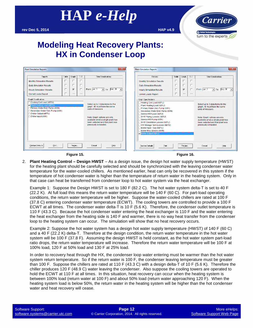
2. Plant Heating Control – Design HWST – As a design issue, the design hot water supply temperature (HWST)for the heating plant should be carefully selected and should be synchronized with the leaving condenser watertemperature for the water-cooled chillers. As mentioned earlier, heat can only be recovered in this system if thetemperature of hot condenser water is higher than the temperature of return water in the heating system. Only inthat case can heat be transferred from condenser loop to hot water system via the heat exchanger.
Example 1: Suppose the Design HWST is set to 180 F (82.2 C). The hot water system delta-T is set to 40 F(22.2 K). At full load this means the return water temperature will be 140 F (60 C). For part-load operatingconditions, the return water temperature will be higher. Suppose the water-cooled chillers are rated at 100 F(37.8 C) entering condenser water temperature (ECWT). The cooling towers are controlled to provide a 100 FECWT at all times. The condenser water delta-T is 10 F (5.6 K). Therefore, the condenser outlet temperature is110 F (43.3 C). Because the hot condenser water entering the heat exchanger is 110 F and the water enteringthe heat exchanger from the heating side is 140 F and warmer, there is no way heat transfer from the condenserloop to the heating system can occur. The simulation will show that no heat recovery occurs.
Example 2: Suppose the hot water system has a design hot water supply temperature (HWST) of 140 F (60 C)and a 40 F (22.2 K) delta-T. Therefore at the design condition, the return water temperature in the hot watersystem will be 100 F (37.8 F). Assuming the design HWST is held constant, as the hot water system part-loadratio drops, the return water temperature will increase. Therefore the return water temperature will be 100 F at100% load, 120 F at 50% load and 130 F at 25% load.
In order to recovery heat through the HX, the condenser loop water entering must be warmer than the hot watersystem return temperature. So if the return water is 100 F, the condenser leaving temperature must be greaterthan 100 F. Suppose the chillers are rated at 110 F (43.3 C) with a design delta-T of 10 F (5.6 K). Therefore thechiller produces 120 F (48.9 C) water leaving the condenser. Also suppose the cooling towers are operated tohold the ECWT at 110 F at all times. In this situation, heat recovery can occur when the heating system isbetween 100% load (return water at 100 F) and about 50% load (return water approaching 120 F). When theheating system load is below 50%, the return water in the heating system will be higher than the hot condenserwater and heat recovery will cease.

Software Support: Page 13 More eHelps:[email protected] © Carrier Corporation, 2014. All rights reserved. Software Support Web Page
Modeling Heat Recovery Plants:HX in Condenser Loop
HAP e-Helprev Dec 5, 2014 HAP v4.9
3. Plant Heating Control – HWST Reset – As noted in Step 4d it can be beneficial to use hot water supplytemperature reset, if heat recovery is used for space heating and if reset is feasible. Hot water reset reduces thehot water supply temperature either as outdoor temperatures warm, or as heating loads decrease. Reduced hotwater supply temperatures can result in cooler return water temperatures in the hot water loop. This can increasethe amount of heat recovery achieved because it increase the heat exchanger delta T between the hot condenserloop water and the heating system return water. It can also increase the number of heat recovery hours in somesystems.
Example: Consider Example #2 from item 2 above. In the heating system, with constant HWST at 140 F (60 C)the heating system return water temperature is 100 F at 100% load, 120 F at 50% load and 130 F at 25% load. Ifthe chillers are rated at 110 F (43.3 C) ECWT with 10 F (5.6 K) delta, the condenser leaving temperature is 120 F(48.9 C). As a result, heat recovery can occur for hours when the heating system is between 100% and 50%load.
Suppose the heating system is changed to use hot water supply temperature reset based on demand, with aminimum HWST of 120 F (48.9 C). Under this control the hot water return temperature is held constant at 100 Fand the supply temperature is reset from 140 F to progressively lower temperatures as the system load dropsuntil it reaches 120 F at 50% system load. This means the heating system return water will be 100 F at 100%load, 100 F at 50% load, 110 F at 25% load and will approach 120 F as load approaches zero. If the water-cooled chillers continue producing 120 F condenser leaving temperatures, then the potential for heat recovery isextended to hours when the heating system load is below 50%. This could be a significant number of additionaloperating hours.
4. Condenser Water Pump Performance – Because of the heat exchanger in the condenser loop, condenserpumps will face additional resistance to flow. Condenser pump performance inputs (head, BHP or kW) mustreflect this additional resistance to produce accurate estimates of condenser pump energy use.
5. Water-Cooled Chiller Performance Data– As noted in step 3 in the HAP tutorial, when defining the data for thewater-cooled chillers, make sure the specified Full Load ECWT, Full Load Capacity, Full Load Power andperformance map data is all synchronized with the temperature levels in the hot water system. This involvesspecifying a sufficiently elevated ECWT and corresponding performance data for the chiller so the chiller canproduce sufficient hot enough condenser leaving water so heat recovery through the heat exchanger can occur.
Further Information
If you have further questions about modeling heat recovery plants using the “heat exchanger in condenser water loop”configuration and you are located in the US or Canada, please contact Carrier software support [email protected]. Otherwise, please contact your local Carrier sales office for assistance.
HAP also offers simulation models for the following five additional heat recovery schemes:
• Air-cooled chillers with heat recovery condensers.• Dedicated heat recovery chiller in parallel with cooling-only chillers.• Dedicated heat recovery chiller (DHRC) in the condenser water loop.• Chiller with double-bundle condenser.• Chiller with desuperheater.
For separate e-Helps explaining how to model these other heat recovery schemes, please visit the Carrier softwareapplication support web page.

![Natural Gas Engine-Driven Chillers Water-Cooled STx / … Cooling Tower Flow [GPM] - Flow To Condenser Only [GPM] - 40Flow To Dump HX Only ... data acquisition and system control by](https://img.pdfslide.us/doc/110x75/5aaff1e67f8b9a59478df696/natural-gas-engine-driven-chillers-water-cooled-stx-cooling-tower-flow-gpm.jpg)


![The SU(2j3) - CORE · 2.3 Two-particle cuts and result7 2.4 Auxiliary one-loop form factors needed for two-loop cuts8 3 Two-loop minimal form factor hX Y Z jTrX[Y;Z]j0i 10 3.1 Two-particle](https://img.pdfslide.us/doc/110x75/5fb7a8d5b112867499088bab/the-su2j3-core-23-two-particle-cuts-and-result7-24-auxiliary-one-loop-form.jpg)