Embed Size (px)
Citation preview
Modeling and Simulation of Grid Connected
Wind Energy Conversion System Based on a
Doubly Fed Induction Generator (DFIG)
Chandrasekaran Subramanian, Domenico Casadei, Angelo Tani, and Claudio Rossi Department of Electrical, Electronics and Information Engineering, University of Bologna, Bologna, Italy
Email: chandras.subramanian, domenico.casadei, angelo.tani, [email protected]
Abstract—This paper deals with the analysis, modeling, and
control of a grid connected doubly-fed induction generator
(DFIG) driven by the wind turbine. Recent advancements in
size and technology of wind turbines require sophisticated
control systems to effectively optimize energy conversion
and enhance grid integration. This article investigates the
power flow analysis of grid connected Wind Energy
Conversion System (WECS) in a highly fluctuating wind
environment. The WECS is equipped with a DFIG and a
back-to-back converter in the rotor circuit. A control
technique is presented for extracting the maximum power
from the wind turbine. The grid side converter maintains
the DC link voltage and the task of the rotor side converter
is to track the maximum power point for the wind turbine.
The description for the proposed system is presented with
the detailed dynamic modeling equations. Simulation results
for different operating conditions are presented.
Index Terms—wind turbine, induction generator, power
converter, modeling, control
I. INTRODUCTION
Due to the economical and environmental benefits,
Wind Energy Conversion System (WECS) have received
tremendous growth in the past decade. The increased
interest in wind energy has made it necessary to model
and experimentally evaluate entire WECS, so as to attain
a better understanding and to assess the performance of
various systems. This paper describes a control strategy
for a doubly fed induction generator (DFIG) with varying
wind speed. Variable speed operation is essential for
large wind turbines in order to optimize the energy
capture under variable wind speed conditions. Variable
speed wind turbines require a power electronic interface
to permit connection with the grid. The power converter
can be either partially rated or fully rated. A popular
interface method for large wind turbines that is based on
a partially rated converter is the doubly-fed induction
generator (DFIG) system [1]. In the DFIG system, the
power converter controls the rotor currents in order to
control the electromagnetic torque and thus the rotational
Manuscript received February 6, 2013; revised August 7, 2014.
speed. Because the power converter only process the slip
rotor power, which is typically 25% of the rated output
power, the DFIG offers the advantages of speed control
for a reduction in cost and power losses [2]-[3]. This
paper presents a DFIG wind turbine system that is
modeled in Matlab/Simulink and PLECS. A full electrical
model is implemented that includes the power converter
for the rotor side and a dq model of the induction
machine. The aerodynamics of the wind turbine and the
mechanical dynamics of the induction machine are
included to extend the use of the model for variable wind
speed conditions. For longer simulations that include
these slower mechanical and wind dynamics, an averaged
PWM converter model is presented. The averaged
electrical model offers improved simulation speed at the
expense of neglecting converter switching detail. The
main feature of the implemented model is the possibility
to investigate topics related to the diagnosis and Low
Voltage Ride Trough (LVRT) capability of WECS.
Simulation results for different operating conditions are
presented in this paper, whereas the LVRT characteristics
will be analyzed in a next paper.
II. MODELING OF THE WIND TURBINE SYSTEM
Fig. 1 shows the overall schematic for DFIG based
wind generation system. The system employs a back to
back converter with reduced power rating. This
bidirectional power converter consists of two
conventional pulse-width modulated (PWM) inverters
and is nowadays one of the most widely used converter
topology in wind energy conversion system. The rotor
side inverter is controlled so as to extract the maximum
power from the wind turbine and to regulate the reactive
power transferred to the utility grid. The main objective
of the grid side inverter is the control of DC link voltage
regardless of the wind speed. The DFIG is based on a
wound rotor type induction machine. The torque speed
profile of a typical induction machine with a short-
circuited rotor is shown in Fig. 2. Thanks to the back-to-
back converter that allows a bidirectional power flow
between the rotor and the grid, the induction machine has
two operating regions, i.e. sub synchronous and super
doi: 10.12720/ijoee.2.2.161-166
International Journal of Electrical Energy, Vol. 2, No. 2, June 2014
©2014 Engineering and Technology Publishing 161
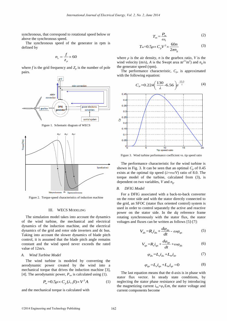
synchronous, that correspond to rotational speed below or
above the synchronous speed.
The synchronous speed of the generator in rpm is
defined by
60s
p
fn
z
where f is the grid frequency and Zp is the number of pole
pairs.
Figure 1. Schematic diagram of WECS
Figure 2. Torque-speed characteristics of induction machine
III. WECS MODELING
The simulation model takes into account the dynamics
of the wind turbine, the mechanical and electrical
dynamics of the induction machine, and the electrical
dynamics of the grid and rotor side inverters and dc bus.
Taking into account the slower dynamics of blade pitch
control, it is assumed that the blade pitch angle remains
constant and the wind speed never exceeds the rated
value of 12m/s.
A. Wind Turbine Model
The wind turbine is modeled by converting the
aerodynamic power created by the wind into a
mechanical torque that drives the induction machine [3],
[4]. The aerodynamic power, Pw, is calculated using (1).
=0.5 ( , ) 3
w pP ρ C λ β V A (1)
and the mechanical torque is calculated with
= wm
t
PT
ω (2)
60=0.5
23
p
g
mn
T ρ C Vπn
(3)
where ρ is the air density, n is the gearbox ratio, V is the
wind velocity (m/s), A is the Swept area πr2 (
m2) and ng is
the generator speed (rpm).
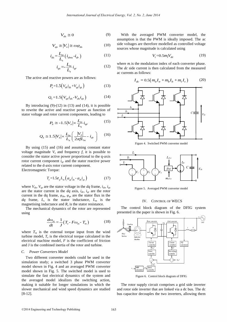
The performance characteristic, Cp, is approximated
with the following equation:
13.3-130
=0.224 -6.56 λPC e
λ
(4)
Figure 3. Wind turbine performance coefficient vs. tip speed ratio
The performance characteristic for the wind turbine is
shown in Fig. 3. It can be seen that an optimal Cp of 0.45
exists at the optimal tip speed (λ=rω/V) ratio of 8.0. The
torque model of the turbine, calculated from (3), is
dependent on two variables, V and ng.
B. DFIG Model
For a DFIG associated with a back-to-back converter
on the rotor side and with the stator directly connected to
the grid, an SFOC (stator flux oriented control) system is
used in order to control separately the active and reactive
power on the stator side. In the dq reference frame
rotating synchronously with the stator flux, the stator
voltages and fluxes can be written as follows [5]-[7]:
= + - dss qsds ds
dφV R i ωφ
dt (5)
= + +qs
qs s qs ds
dφV R i ωφ
dt (6)
= +s mds ds drφ L i L i (7)
= + =0qs s qs m qrφ L i L i (8)
The last equation means that the d-axis is in phase with
stator flux vector. In steady state conditions, by
neglecting the stator phase resistance and by introducing
the magnetizing current ims=φs/Lm, the stator voltage and
current components become
International Journal of Electrical Energy, Vol. 2, No. 2, June 2014
©2014 Engineering and Technology Publishing 162
0dsV (9)
qs s dsV V ωφ (10)
= -mds dms dr
s
Li i i
L (11)
=- mqs qr
s
iL
iL
(12)
The active and reactive powers are as follows:
= +1.5s ds ds qs qsV i V iP (13)
=1.5 -s qs qsds dsQ V i V i (14)
By introducing (9)-(12) in (13) and (14), it is possible
to rewrite the active and reactive power as function of
stator voltage and rotor current components, leading to
1.5- ms qr
ss
LP V i
L (15)
1.5 - 2
mdr
m
ss s
s
QVL
V iL πfL
(16)
By using (15) and (16) and assuming constant stator
voltage magnitude Vs and frequency f, it is possible to
consider the stator active power proportional to the q-axis
rotor current component iqr and the stator reactive power
related to the d-axis rotor current component.
Electromagnetic Torque:
=1.5 - e p m qs ds ds qs
T L φ i φ iz (17)
where Vds, Vqs are the stator voltage in the dq frame, ids, iqs
are the stator current in the dq axis, idr, iqr are the rotor
current in the dq frame, φds, φqs are the stator flux in the
dq frame, Ls is the stator inductance, Lm is the
magnetising inductance and Rs is the stator resistance.
The mechanical dynamics of the rotor are represented
using
1
= - - me m m
dωT Fω T
dt J (18)
where Tm is the external torque input from the wind
turbine model, Te is the electrical torque calculated in the
electrical machine model, F is the coefficient of friction
and J is the combined inertia of the rotor and turbine.
C. Power Converters Model
Two different converter models could be used in the
simulation study; a switched 3 phase PWM converter
model shown in Fig. 4 and an averaged PWM converter
model shown in Fig. 5. The switched model is used to
simulate the fast electrical dynamics of the system and
the averaged model idealizes the switching action,
making it suitable for longer simulations in which the
slower mechanical and wind speed dynamics are studied
[8-12].
With the averaged PWM converter model, the
assumption is that the PWM is ideally imposed. The ac
side voltages are therefore modelled as controlled voltage
sources whose magnitude is calculated using
i 0.5= i dcV mV (19)
where mi is the modulation index of each converter phase.
The dc side current is then calculated from the measured
ac currents as follows:
0.5= + +a a c cdc b bI m I m I m I (20)
Figure 4. Switched PWM converter model
Figure 5. Averaged PWM converter model
IV. CONTROL OF WECS
The control block diagram of the DFIG system
presented in the paper is shown in Fig. 6.
Figure 6. Control block diagram of DFIG
The rotor supply circuit comprises a grid side inverter
and rotor side inverter that are linked via a dc bus. The dc
bus capacitor decouples the two inverters, allowing them
International Journal of Electrical Energy, Vol. 2, No. 2, June 2014
©2014 Engineering and Technology Publishing 163
to be independently controlled [12-15]. The parameters of
the turbine and induction machine are given in Table I.
The parameters have been adapted from a GE 1.5MW
turbine [3]. It should be noted that the inertia was reduced
by a factor of five in order to speed up the mechanical
dynamic response of the turbine and allow for a faster
simulation.
TABLE I. WECS PARAMETERS
Rated Power 1.5MW Frequency 50Hz
Rated Voltage 575Vrms Pole pairs 2
Stator resistance 1.4mΩ Lm 1.53mH
Rotor resistance 0.99mΩ Lr 1.61mH
Bus capacitance 38mF Ls 1.62mH
Turbine radius 35m Inertia 50kg.m2
A. Grid Side Inverter (GSI) Control
The task of the grid side inverter is to regulate the
voltage of the dc bus, Vdc. To achieve this, a voltage
control loop controls the q-axis current, Iq* that affects
the real power exported to or imported from the grid. The
grid side converter can also be used for system power
factor control by adding a reactive power control loop to
control the d-axis current. In the example system, unity
power factor operation is assumed and the d-axis current
reference is therefore set to zero.
B. Rotor Side Inverter (RSI) Control
The purpose of the rotor inverter is to control the
generator speed to achieve maximum power from the
wind over a range of wind velocities. The rotor side
inverter control scheme is based on a multitiered structure
that comprises a speed, power and current control loop. It
should be noted that omission of the power control loop
is possible by implementing decoupled current control [8].
The reference speed for the outer speed control loop is
determined by a maximum power point (MPP)
calculation based on the wind velocity. Speed control is
implemented by controlling the real power reference to
the power control loop. In the power control loop, the
reactive power reference is set to zero because it is
assumed that the grid side converter will supply the
needed reactive power to the system. The current
controller tracks the power reference by controlling the
rotor currents. Current control is performed in a dq
reference frame that is rotating with the stator flux.
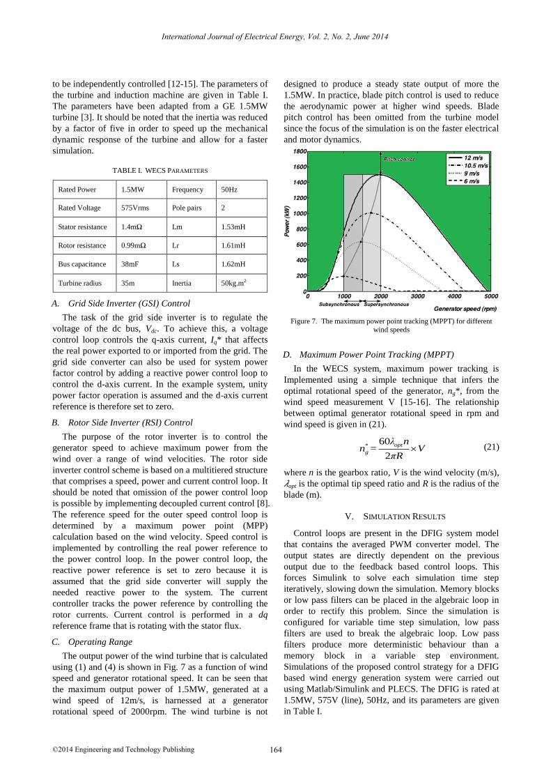
C. Operating Range
The output power of the wind turbine that is calculated
using (1) and (4) is shown in Fig. 7 as a function of wind
speed and generator rotational speed. It can be seen that
the maximum output power of 1.5MW, generated at a
wind speed of 12m/s, is harnessed at a generator
rotational speed of 2000rpm. The wind turbine is not
designed to produce a steady state output of more the
1.5MW. In practice, blade pitch control is used to reduce
the aerodynamic power at higher wind speeds. Blade
pitch control has been omitted from the turbine model
since the focus of the simulation is on the faster electrical
and motor dynamics.
Figure 7. The maximum power point tracking (MPPT) for different wind speeds
D. Maximum Power Point Tracking (MPPT)
In the WECS system, maximum power tracking is
Implemented using a simple technique that infers the
optimal rotational speed of the generator, ng*, from the
wind speed measurement V [15-16]. The relationship
between optimal generator rotational speed in rpm and
wind speed is given in (21).
60=
2
opt*
g
λ nn V
πR (21)
where n is the gearbox ratio, V is the wind velocity (m/s),
𝜆opt is the optimal tip speed ratio and R is the radius of the
blade (m).
V. SIMULATION RESULTS
Control loops are present in the DFIG system model
that contains the averaged PWM converter model. The
output states are directly dependent on the previous
output due to the feedback based control loops. This
forces Simulink to solve each simulation time step
iteratively, slowing down the simulation. Memory blocks
or low pass filters can be placed in the algebraic loop in
order to rectify this problem. Since the simulation is
configured for variable time step simulation, low pass
filters are used to break the algebraic loop. Low pass
filters produce more deterministic behaviour than a
memory block in a variable step environment.
Simulations of the proposed control strategy for a DFIG
based wind energy generation system were carried out
using Matlab/Simulink and PLECS. The DFIG is rated at
1.5MW, 575V (line), 50Hz, and its parameters are given
in Table I.
International Journal of Electrical Energy, Vol. 2, No. 2, June 2014
©2014 Engineering and Technology Publishing 164
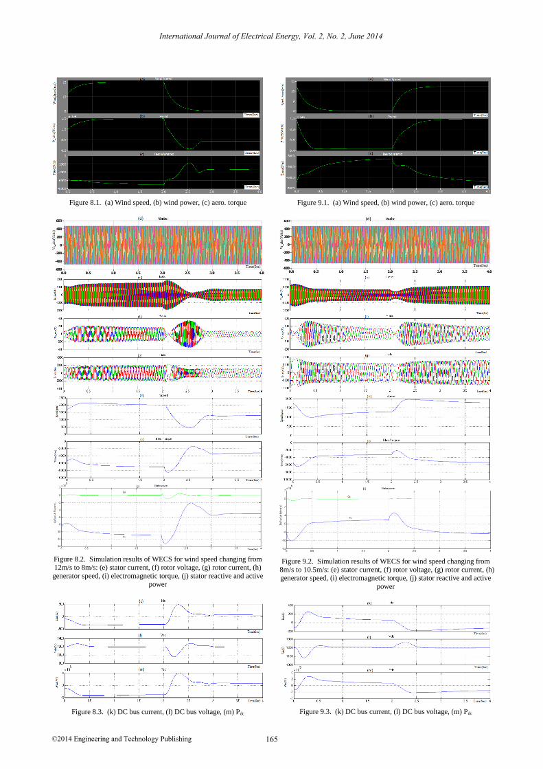
Figure 8.1. (a) Wind speed, (b) wind power, (c) aero. torque
Figure 8.2. Simulation results of WECS for wind speed changing from 12m/s to 8m/s: (e) stator current, (f) rotor voltage, (g) rotor current, (h)
generator speed, (i) electromagnetic torque, (j) stator reactive and active power
Figure 8.3. (k) DC bus current, (l) DC bus voltage, (m) Pdc
Figure 9.1. (a) Wind speed, (b) wind power, (c) aero. torque
Figure 9.2. Simulation results of WECS for wind speed changing from 8m/s to 10.5m/s: (e) stator current, (f) rotor voltage, (g) rotor current, (h) generator speed, (i) electromagnetic torque, (j) stator reactive and active
power
Figure 9.3. (k) DC bus current, (l) DC bus voltage, (m) Pdc
International Journal of Electrical Energy, Vol. 2, No. 2, June 2014
©2014 Engineering and Technology Publishing 165
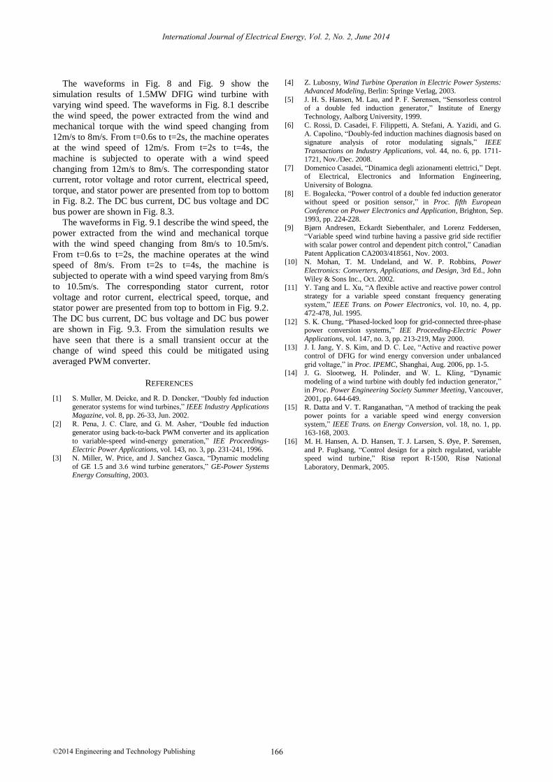
The waveforms in Fig. 8 and Fig. 9 show the
simulation results of 1.5MW DFIG wind turbine with
varying wind speed. The waveforms in Fig. 8.1 describe
the wind speed, the power extracted from the wind and
mechanical torque with the wind speed changing from
12m/s to 8m/s. From t=0.6s to t=2s, the machine operates
at the wind speed of 12m/s. From t=2s to t=4s, the
machine is subjected to operate with a wind speed
changing from 12m/s to 8m/s. The corresponding stator
current, rotor voltage and rotor current, electrical speed,
torque, and stator power are presented from top to bottom
in Fig. 8.2. The DC bus current, DC bus voltage and DC
bus power are shown in Fig. 8.3.
The waveforms in Fig. 9.1 describe the wind speed, the
power extracted from the wind and mechanical torque
with the wind speed changing from 8m/s to 10.5m/s.
From t=0.6s to t=2s, the machine operates at the wind
speed of 8m/s. From t=2s to t=4s, the machine is
subjected to operate with a wind speed varying from 8m/s
to 10.5m/s. The corresponding stator current, rotor
voltage and rotor current, electrical speed, torque, and
stator power are presented from top to bottom in Fig. 9.2.
The DC bus current, DC bus voltage and DC bus power
are shown in Fig. 9.3. From the simulation results we
have seen that there is a small transient occur at the
change of wind speed this could be mitigated using
averaged PWM converter.
REFERENCES
[1] S. Muller, M. Deicke, and R. D. Doncker, “Doubly fed induction generator systems for wind turbines,” IEEE Industry Applications
Magazine, vol. 8, pp. 26-33, Jun. 2002.
[2] R. Pena, J. C. Clare, and G. M. Asher, “Double fed induction generator using back-to-back PWM converter and its application
to variable-speed wind-energy generation,” IEE Proceedings-Electric Power Applications, vol. 143, no. 3, pp. 231-241, 1996.
[3] N. Miller, W. Price, and J. Sanchez Gasca, “Dynamic modeling
of GE 1.5 and 3.6 wind turbine generators,” GE-Power Systems Energy Consulting, 2003.
[4] Z. Lubosny, Wind Turbine Operation in Electric Power Systems: Advanced Modeling, Berlin: Springe Verlag, 2003.
[5] J. H. S. Hansen, M. Lau, and P. F. Sørensen, “Sensorless control
of a double fed induction generator,” Institute of Energy Technology, Aalborg University, 1999.
[6] C. Rossi, D. Casadei, F. Filippetti, A. Stefani, A. Yazidi, and G. A. Capolino, “Doubly-fed induction machines diagnosis based on
signature analysis of rotor modulating signals,” IEEE
Transactions on Industry Applications, vol. 44, no. 6, pp. 1711-1721, Nov./Dec. 2008.
[7] Domenico Casadei, “Dinamica degli azionamenti elettrici,” Dept. of Electrical, Electronics and Information Engineering,
University of Bologna.
[8] E. Bogalecka, “Power control of a double fed induction generator without speed or position sensor,” in Proc. fifth European
Conference on Power Electronics and Application, Brighton, Sep. 1993, pp. 224-228.
[9] Bjørn Andresen, Eckardt Siebenthaler, and Lorenz Feddersen,
“Variable speed wind turbine having a passive grid side rectifier with scalar power control and dependent pitch control,” Canadian
Patent Application CA2003/418561, Nov. 2003. [10] N. Mohan, T. M. Undeland, and W. P. Robbins, Power
Electronics: Converters, Applications, and Design, 3rd Ed., John
Wiley & Sons Inc., Oct. 2002. [11] Y. Tang and L. Xu, “A flexible active and reactive power control
strategy for a variable speed constant frequency generating system,” IEEE Trans. on Power Electronics, vol. 10, no. 4, pp.
472-478, Jul. 1995.
[12] S. K. Chung, “Phased-locked loop for grid-connected three-phase power conversion systems,” IEE Proceeding-Electric Power
Applications, vol. 147, no. 3, pp. 213-219, May 2000. [13] J. I. Jang, Y. S. Kim, and D. C. Lee, “Active and reactive power
control of DFIG for wind energy conversion under unbalanced
grid voltage,” in Proc. IPEMC, Shanghai, Aug. 2006, pp. 1-5. [14] J. G. Slootweg, H. Polinder, and W. L. Kling, “Dynamic
modeling of a wind turbine with doubly fed induction generator,” in Proc. Power Engineering Society Summer Meeting, Vancouver,
2001, pp. 644-649.
[15] R. Datta and V. T. Ranganathan, “A method of tracking the peak power points for a variable speed wind energy conversion
system,” IEEE Trans. on Energy Conversion, vol. 18, no. 1, pp. 163-168, 2003.
[16] M. H. Hansen, A. D. Hansen, T. J. Larsen, S. Øye, P. Sørensen,
and P. Fuglsang, “Control design for a pitch regulated, variable speed wind turbine,” Risø report R-1500, Risø National
Laboratory, Denmark, 2005.
International Journal of Electrical Energy, Vol. 2, No. 2, June 2014
©2014 Engineering and Technology Publishing 166