Embed Size (px)
Citation preview
Manuscript received February 13, 2016; revised May 25, 2016; accepted August 7, 2016. Paper 2016-IPCC-0087.R1, presented at the 2015 IEEE Energy Conversion Congress and Exposition, Montreal, QC, Canada, September 20–24, and approved for publication in the IEEE TRANSACTIONS ON INDUSTRY APPLICATIONS by the IEEE-IAS Industrial Power Converter Committee of the IEEE Industry Applications Society.
Model Predictive control for Shunt Active Filters with
Fixed Switching Frequency Luca Tarisciotti, Andrea Formentini, Alberto Gaeta, Marco Degano, Pericle Zanchetta
Roberto Rabbeni, Marcello Pucci, Marco Rivera
Abstract- This paper presents a modification to the classical
Model Predictive Control algorithm, named Modulated Model
Predictive Control, and its application to active power filters. The
proposed control is able to retain all the advantages of a Finite
Control Set Model Predictive Control whilst improving the
generated waveforms harmonic spectrum. In fact a modulation
algorithm, based on the cost function ratio for different output
vectors, is inherently included in the MPC. The cost function-
based modulator is introduced and its effectiveness on reducing
the current ripple is demonstrated. The presented solution
provides an effective and straightforward single loop controller,
maintaining an excellent dynamic performance despite the
modulated output and it is self-synchronizing with the grid. This
promising method is applied to the control of a Shunt Active
Filter for harmonic content reduction through a reactive power
compensation methodology. Significant results obtained by
experimental testing are reported and commented, showing that
MPC is a viable control solution for active filtering systems.
Keywords: Smart Grids; Power Quality; Active Filters; Power
Filters; Harmonic Distortion; Model Predictive Control.
I. INTRODUCTION
Maintaining a good power quality level in modern electrical
grids is a vital issue to ensure reliability, security and
efficiency [1]. This is currently becoming extremely important
due to the proliferation of non-linear loads, power conversion
systems, renewable energy sources (RES), distributed
generation sources (DG) and Plug-in Electric Vehicles (PEVs)
[2]. Several Flexible AC Transmission System (FACTS)
equipment [2], [3] have been recently investigated and applied
in order to improve the electrical grid power quality. These
studies resulted in a broad family of devices, such as Active
and Hybrid power filters [4], [5], Static compensators
(STATCOM) [6], [7], Static VAR Compensators (SVC) [8],
Unified Power Flow/Quality Controllers (UPFC/UPQC) and
Dynamic Voltage Restorers (DVR). In particular, Active
powers filters allow to increase the overall system power
quality and are not affected by the limits of their passive
counterparts, such as the introduction of resonances onto the
power system, impossibility of current limiting (other than
fuses), overloaded operation if the supply voltage quality
deteriorates [9]. However, the control of an Active Filter [10]
requires fast dynamic performances and represents a
challenging control problem, which may not be able to be
addressed by applying linear control techniques. In fact, as a
high control bandwidth is required, it may happen that the
required sampling frequency became excessively high.
Moreover, supply disturbances may be hard to suppress using
classical PI controllers [11], [12]. Among all possible Active
Filter configurations, the Shunt Active Filter (SAF) is the most
commonly applied, and several control techniques has been
proposed in literature to fulfill its high bandwidth
requirements. In fact, PI controllers in a stationary reference
frame are unable to provide a satisfactory regulation, given the
high frequency of the harmonics to control, and they fail to
eliminate steady state error and to achieve satisfactory tracking
of the desired reference. Other control schemes aim to improve
the tracking accuracy for specified harmonics by using
multiple related synchronous reference frames [13], [14].
However, the need for multiple band-pass filters and the
consequent interactions among them increase the complexity
of the control tuning. Alternatively, to avoid multiple reference
frame transformations, Proportional Resonant (PR) controllers
may be used [15]. Techniques which reduce the number of
measurements required by the system have also been
investigated, typically based on time domain controllers and
an appropriate observer [16]. Finally, Dead-Beat control
strategies have also been considered [17], coupled with a PI
based DC-Link voltage control.
Model Predictive Control (MPC) has been recently adopted
for power electronics converters control, due to the several
benefits it can provide such as, fast tracking response and
simple inclusion of system nonlinearities and constraints in the
controller [18]. MPC considers the system model for
predicting its future behavior and determining the best control
action on the basis of a cost function minimization procedure.
Finite Control Set MPC (FCS-MPC) is a model based
control strategy applicable to systems with a finite number of
possible control actions, such as power electronic converters.
At each sample time FCS-MPC computes a target cost
function for every possible control action: the one associated
to the minimum cost function value is selected as optimal
control and applied [19]. This technique has been successfully
applied for the control of three-phase inverters [20], [21],
matrix converters [22], [23], power control in an active front
end rectifiers [24], [25], and regulation of both electrical and
mechanical variables in drive system applications [26]–[30].
The lack of a modulator, although being an advantage for
the transient performance of the system, it is also a drawback
under steady-state conditions when the high bandwidth of the
control is not necessary and the higher current ripple, due to
the limited set of available control actions, is more evident.
This paper presents a novel Finite Control Set Modulated
MPC (FCS-M2PC) algorithm suitable for SAF control, which
retains most of the advantages of the MPC such as the presence
of a cost function and the use of a single loop for improved
responsivity and larger bandwidth, but exploits a modulator
for reducing the current ripple. The cost function minimization
procedure acts also as a modulator, by selecting the best
vectors and their application times for the next sampling
period. A similar solution has already been proposed in [31]–
[33] for a Multilevel Cascaded H-Bridge Converter, in [34],
[35] for a Direct Matrix Converter and in [36] for a three phase
Active Filter . Experimental results show the excellent
transient and steady state performance of the proposed system.
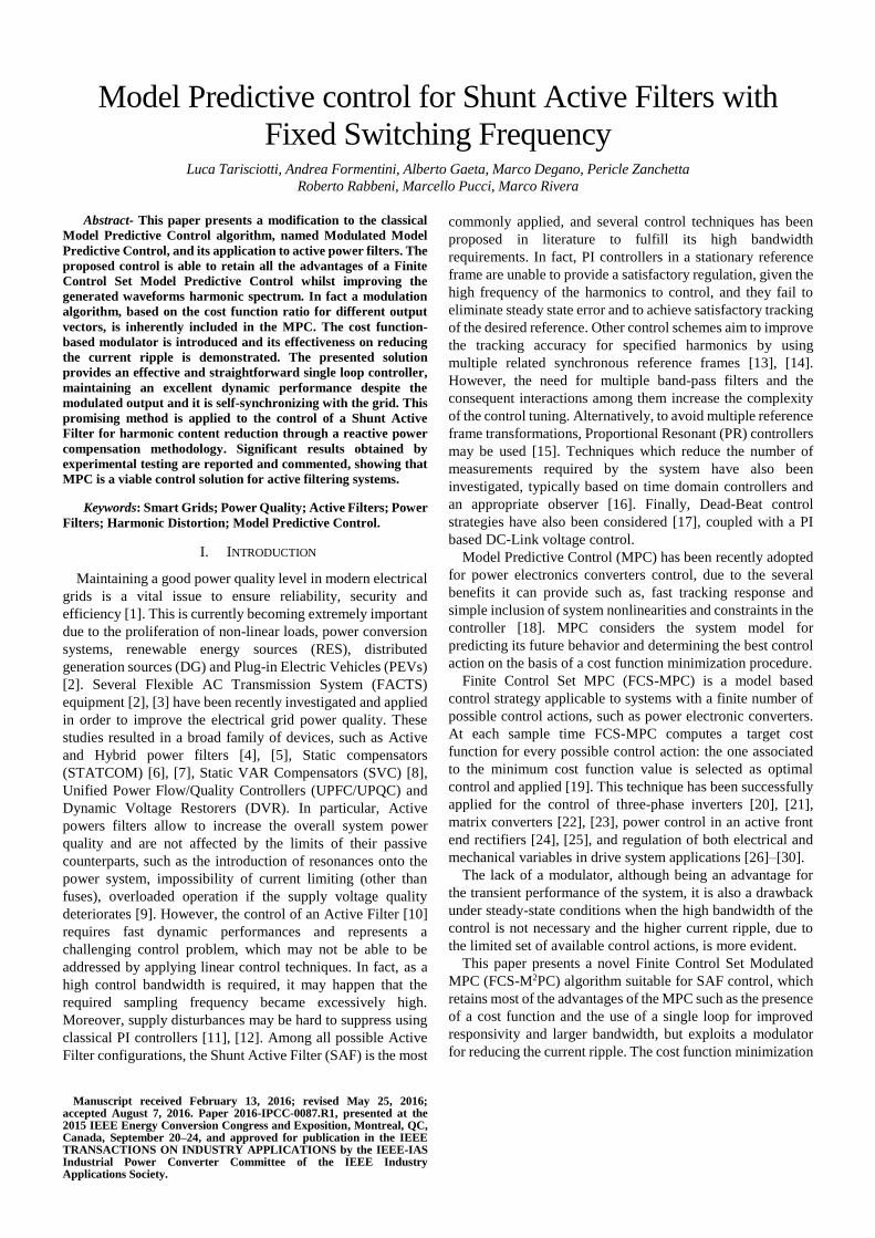
II. SYSTEM DESCRIPTION AND MODELING
A SAF is realized by connecting a Voltage Source Converter
(VSC) to the AC grid through filter inductors in a rectifier
configuration. The DC side is connected to a capacitor as
depicted in Fig. 1, and thus, it is able to manage only reactive
power. In such configuration, the SAF is able to produce any
set of balanced currents and, therefore, compensates the
reactive power and current harmonics drawn by a non-linear
load; clearly the SAF filtering capabilities are limited by the
VSC rated power and control bandwidth. On the other hand,
the grid provides only the active power required to supply the
load and maintain the SAF DC-Link at the desired voltage.
Fig.1: Adopted structure of 3-wires Shunt Active Filter
When a balanced system is considered, it is possible to
reduce the system order to the third order, represented in the
abc frame by the state variables ifa(t), ifb(t) and Vdc(t).
Neglecting the nonlinearities introduced by the inverter and
the equivalent impedance of the grid, the SAF currents
equations can be expressed as follows:
{
𝑑𝑖𝑓𝑎(𝑡)
𝑑𝑡=
1
𝐿𝑓𝑣𝑠𝑎(𝑡) −
𝑅𝑓
𝐿𝑓𝑖𝑓𝑎(𝑡) −
1
3𝐿𝑓[2𝑆𝑎(𝑡) − 𝑆𝑏(𝑡) − 𝑆𝑐(𝑡)]𝑉𝑑𝑐
𝑑𝑖𝑓𝑏(𝑡)
𝑑𝑡=
1
𝐿𝑓𝑣𝑠𝑏(𝑡) −
𝑅𝑓
𝐿𝑓𝑖𝑓𝑏(𝑡) −
1
3𝐿𝑓[2𝑆𝑏(𝑡) − 𝑆𝑎(𝑡) − 𝑆𝑐(𝑡)]𝑉𝑑𝑐
(1)
where Rf and Lf are the filter inductor winding resistance and
inductance. Sa(t), Sb(t) and Sc(t) represent each leg state, equal
to 1 or 0 respectively when a positive or a negative voltage is
produced at the leg output with respect to the DC-Link neutral
point. The DC-Link voltage can be obtained by the converter
state and the DC current, derived by the converter switching
functions and AC currents, as shown in equation (2).
𝑑𝑉𝑑𝑐(𝑡)
𝑑𝑡=
1
𝐶{[𝑆𝑎(𝑡) − 𝑆𝑐(𝑡)]𝑖𝑓𝑎(𝑡) + [𝑆𝑏(𝑡) − 𝑆𝑐(𝑡)]𝑖𝑓𝑏(𝑡)}(2)
Finally, the supply current can be obtained by the filter and
load currents as in (3).
{𝑖𝑠𝑎(𝑡) = 𝑖𝑙𝑎(𝑡) + 𝑖𝑓𝑎(𝑡)
𝑖𝑠𝑏(𝑡) = 𝑖𝑙𝑏(𝑡) + 𝑖𝑓𝑏(𝑡) (3)
By combining equations (1)-(3) the SAF state space model
can be derived and then discretized using Forward Euler
method for control design purposes. The obtained system is
shown in (4)
{
𝑖𝑓𝑎(𝑘 + 1) = (1 −
𝑅𝑓ℎ
𝐿𝑓) 𝑖𝑓𝑎(𝑘) −
ℎ
𝐿𝑓𝑄1𝑆(𝑘)𝑉𝑑𝑐(𝑘) +
ℎ
𝐿𝑓𝑣𝑠𝑎(𝑘)
𝑖𝑓𝑏(𝑘 + 1) = (1 −𝑅𝑓ℎ
𝐿𝑓) 𝑖𝑓𝑏(𝑘) −
ℎ
𝐿𝑓𝑄2𝑆(𝑘)𝑉𝑑𝑐(𝑘) +
ℎ
𝐿𝑓𝑣𝑠𝑏(𝑘)
𝑉𝑑𝑐(𝑘 + 1) = 𝑉𝑑𝑐(𝑘) +ℎ
𝐶𝑃1𝑆(𝑘)𝑖𝑓𝑎(𝑘) +
ℎ
𝐶𝑃2𝑆(𝑘)𝑖𝑓𝑏(𝑘)
(4)
where k represents the discrete sampling instant, h is the
sampling time, and
𝑄1 =1
3[2 −1 −1] 𝑄2 =
1
3[−1 2 −1]
𝑃1 = [1 0 −1] 𝑃2 = [0 1 −1]
𝑆(𝑘) = [𝑆𝑎(𝑘)𝑆𝑏(𝑘)𝑆𝑐(𝑘)]𝑇
(5)
III. SAF MODEL PREDICTIVE CONTROL
In FCS-MPC, due to the absence of a modulator, the only
possible control actions are the ones generated by the 8
possible inverter switching states:
𝑆(𝑘) ≜ {[000] , [001] , [010] , [011] , [100] , [101] , [110] , [111]} (6)
At the kth time instant the controller uses equation (4) to
predict the future system state value for each possible control
action in (6). A cost function is then computed using a
combination of predicted system states and references. The
optimal control is selected by choosing the inverter
configuration associated to the minimum cost function value.
However, in practical implementation the computed optimal
control action can be applied only at the k+1th time instant, due
to controller computational time delay. This introduces a one-
step delay in the system that must be compensated [21]. At the
kth time instant, the system state at k+1 is predicted using the
previously computed optimal control. Subsequently the
procedure described before is performed starting from the
k+1th time instant resulting in the optimal inverter switching
state S(k+1).
Combining the system model at the time instants k+1 and
k+2, and assuming that the supply voltages can be considered
constant during a sampling period h of the control algorithm
(i.e. vs(k)=vs(k+1)) the following system is obtained.
𝑋(𝑘 + 2) = 𝐴2 (𝑆(𝑘 + 1)) 𝑋(𝑘) + 𝐵2𝑈(𝑘) (7)
The definition of the matrix elements are given in Appendix
I, while 𝑋(𝑘) and 𝑈(𝑘), shown in equation (8), represent the
predicted values of active filter currents and voltages at the
instant k+2 and the supply voltages at the time instant k.
𝑋(𝑘 + 2) = [𝑖𝑓𝑎(𝑘 + 2) 𝑖𝑓𝑏(𝑘 + 2) 𝑉𝑑𝑐(𝑘 + 2)]𝑇
𝑈(𝑘) = [𝑣𝑠𝑎(𝑘) 𝑣𝑠𝑏(𝑘)]𝑇
(8)
The load currents ila and ilb are assumed to be measurable in
the considered configuration. Given the high controller
sampling frequency, it is acceptable to have:
𝑖𝑠𝑎(𝑘 + 2) = 𝑖𝑙𝑎(𝑘) + 𝑖𝑓𝑎(𝑘 + 2)
𝑖𝑠𝑏(𝑘 + 2) = 𝑖𝑙𝑏(𝑘) + 𝑖𝑓𝑏(𝑘 + 2) (9)
Hence the predicted system state is defined as:
𝑋𝑝(𝑘 + 2) = [𝑖𝑠𝑎(𝑘 + 2) 𝑖𝑠𝑏(𝑘 + 2) 𝑉𝑑𝑐(𝑘 + 2)]𝑇 (10)
From (10) the control relevant variables (the active power
Ps, the reactive power Qs and the DC-Link voltage Vdc are
predicted as shown in (11).
𝑃𝑠𝑝(𝑘 + 2) = 𝑣𝑠𝑇(𝑘) [
2 1 01 2 0
]𝑋𝑝(𝑘 + 2)
𝑄𝑠𝑝(𝑘 + 2) = 𝑣𝑠𝑇(𝑘) [
0 √3 0
−√3 0 0]𝑋𝑝(𝑘 + 2)
𝑉𝑑𝑐𝑝(𝑘 + 2) = [0 0 1]𝑋𝑝(𝑘 + 2)
(11)
The 50Hz grid voltages is supposed approximately constant
in two consecutive sampling periods due to the much higher
sampling frequency of the SAF control algorithm. The cost
function adopted in this work to compute the optimal control
action S(k+1) is defined in (12), where x* indicate reference
values and 𝜆1, 𝜆2 and 𝜆3 are weighting factors that allow a
proper balance among deviations of the controlled variables.
𝐽 (𝑆(𝑘 + 1)) = 𝜆1|𝑉𝑑𝑐∗ (𝑘 + 2) − 𝑉𝑑𝑐𝑝(𝑘 + 2)|
+𝜆2|𝑃𝑠∗(𝑘 + 2) − 𝑃𝑠𝑝(𝑘 + 2)| (12)
+𝜆3|𝑄𝑠∗(𝑘 + 2) − 𝑄𝑠𝑝(𝑘 + 2)|
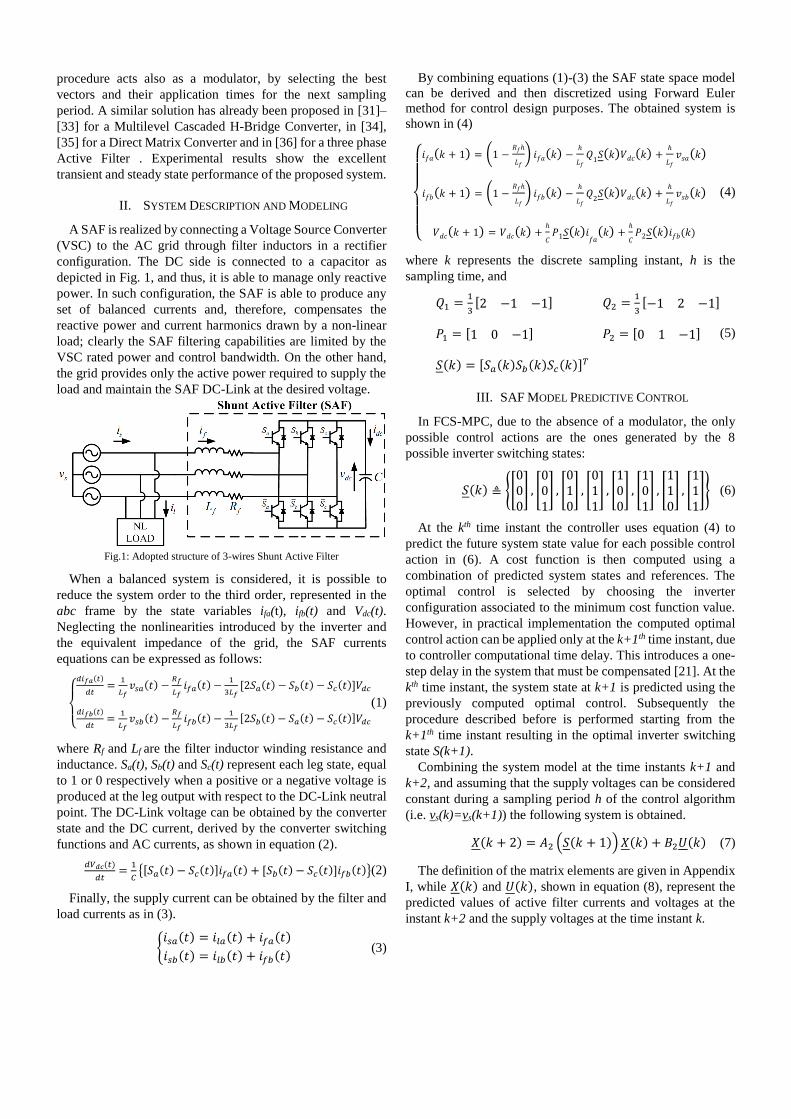
A block scheme of the complete active filter control for the case
of FCS-MPC is shown in Fig. 2.
IV. MODULATED MODEL PREDICTIVE CONTROL
One of the major strength of the FCS-MPC is that it enables
to include in a single control law different control targets and
system constraints. In this way the traditional control of
currents, voltages or flux can be combined with other
requirements like common mode voltage reduction, switching
frequency minimization and reactive power control. However
with FCS-MPC, at each sampling time, all the possible control
actions are compared by means of a cost function and only the
best one is selected for the next sampling period. If the
converter state is constant during a sampling period, the
quantities under control are affected by a higher ripple as a
consequence of the finite number of possible converter states.
Fig.2: Schematic diagram of a FCS-MPC.
To overcome this limit, but still maintaining all the desired
characteristics of FCS-MPC, this paper proposes the
introduction of a suitable intrinsic modulation scheme.
Consistently with the MPC approach, the cost-function is used
for selecting the converter states and application times which
minimize the equivalent cost in a sampling period. A
symmetric PWM pattern with adjacent states has been
preferred for reducing harmonics, ripple and losses. Each
sampling period is composed of two zero states and two active
states which are symmetrically split around the center of the
sampling period. Using the predictions for the traditional FCS-
MPC described in the previous section, a cost function has
been defined for each sector of the αβ plane as in (13), where
𝐽𝑖 with 𝑖 = 0,1,2 are the cost functions calculated as in (12) for
the three vectors considered from the control, thus assuming
Si(k+1) equal respectively to the zero vector, the first active
vector and the second active vector of the considered sector.
𝐽𝑠𝑒𝑐𝑡(𝑘 + 1) = 𝑑0𝐽0 + 𝑑1𝐽1 + 𝑑2𝐽2 (13)
Similarly 𝑑𝑖 are the duty cycles for the zero and active vectors.
They are computed assuming each duty cycle proportional to
the inverse of the corresponding cost function value, where K
is a normalizing constant to be determined.
{
𝑑1 =
𝐾𝐽1⁄
𝑑2 =𝐾𝐽2⁄
𝑑0 =𝐾𝐽0⁄
𝑑1 + 𝑑2 + 𝑑3 = 1
(14)
Solving (14) the expression of the duty cycle is obtained as in
(15).
𝑑1 =𝐽2
𝐽1+𝐽2+𝐽1𝐽2𝐽0
𝑑2 =𝐽1
𝐽1+𝐽2+𝐽1𝐽2𝐽0
𝑑0 = 1 − (𝑑1 + 𝑑2)
(15)
Essentially the cost function values 𝐽𝑖 for each sector are
calculated by using (7)-(12) and the corresponding application
times are calculated from (15).
The optimum sector is then determined by minimizing the
cost function (13). The corresponding optimal duty cycles
𝑑(𝑘 + 1) = [𝑑1(𝑘 + 1) 𝑑2(𝑘 + 1) 𝑑0(𝑘 + 1)]𝑇 are applied to
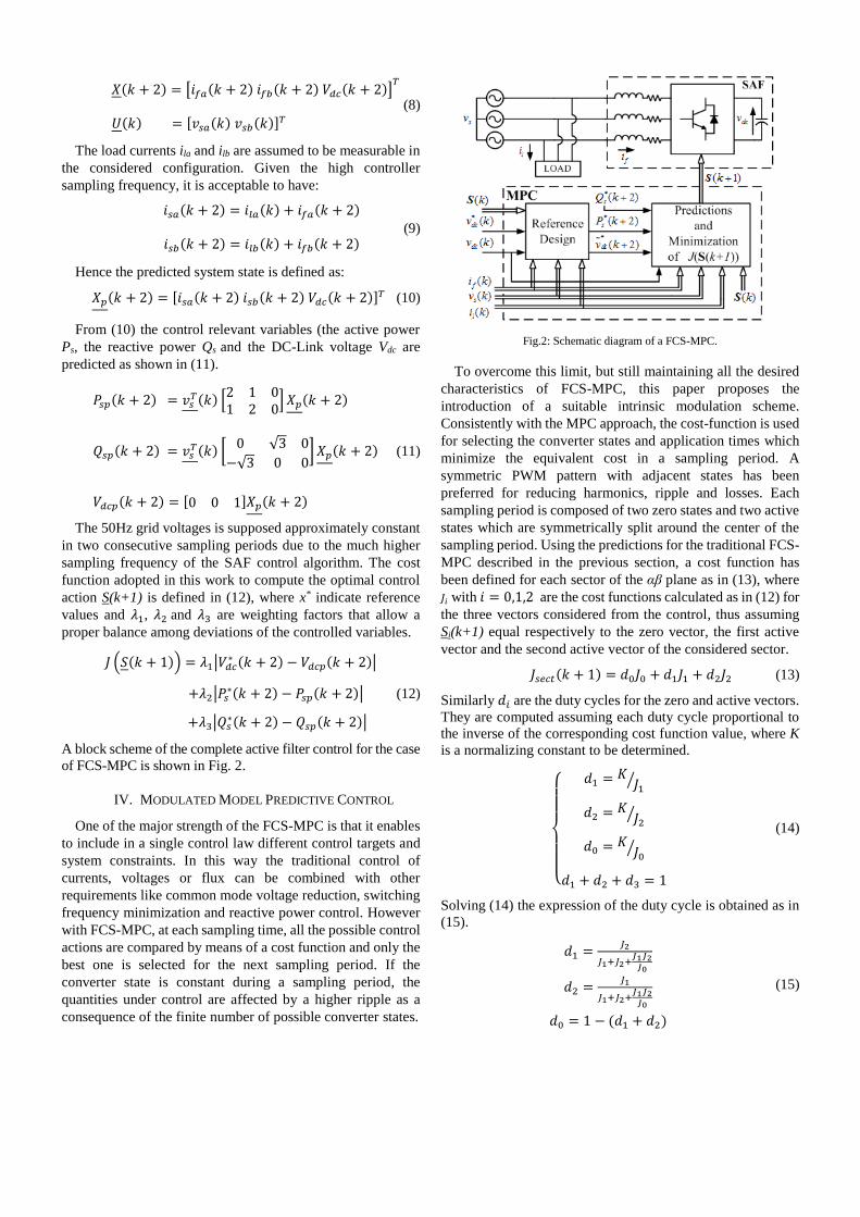
the converter as represented in Fig.3. The switching sequence
is generated from the two active and the three zero vector
exactly as in a symmetrical SVM [37].
Fig.3: Schematic diagram of the proposed FCS-M2PC.
V. REFERENCES PREDICTION
The coupling between active power 𝑃𝑠(𝑘) and DC-Link
voltage 𝑉𝑑𝑐(𝑘), needs to be taken into account when the
related reference signals are calculated. In fact, from the DC-
Link voltage reference 𝑉𝑑𝑐∗ (𝑘) and the reactive power
reference 𝑄𝑠∗(𝑘) at the instant k, it is possible to calculate,
knowing the AC current values, the active power reference at
the time instant k+2, 𝑃𝑠∗(𝑘 + 2). Since the DC-Link capacitors
compensate for the reactive power fluctuations due to the non-
linear load, the dynamics of the DC-Link voltage has to be
maintained considerably slower than the respective reactive
power dynamic. The required change in the active power flow
to regulate the voltage at the desired value is given by equation
(16), where N denotes the number of time steps required for
reaching the target.
𝑃𝐷𝐶(𝑘 + 2) = 𝐶
𝑁ℎ[𝑉𝑑𝑐
∗ 2(𝑘 + 2) − 𝑉𝑑𝑐2(𝑘 + 1)] (16)
The load active power reference can be calculated as in
equation (17), where 𝑖𝑙1(𝑘) = [𝑖𝑙𝑎1(𝑘)𝑖𝑙𝑏1(𝑘)]𝑇 represents the
vector of the first harmonic of the load current.
𝑃𝑙∗(𝑘 + 2) = 𝑣𝑠
𝑇(𝑘) (2 11 2
) 𝑖𝑙1(𝑘) (17)
Thanks to the high controller sampling frequency, it is
acceptable to approximate 𝑖𝑙1(𝑘) = 𝑖𝑙1(𝑘 + 2). The active power
𝑃𝑙∗(𝑘 + 2) is simply obtained by filtering (17) with a digital
resonant filter having a resonance frequency equal to 50Hz.
Finally, the total reference power at the supply side is
therefore:
𝑃𝑠∗(𝑘 + 2) = 𝑃𝑙
∗(𝑘 + 2) + 𝑃𝐷𝐶(𝑘 + 2) (18)
Equation (18), together with 𝑄𝑠∗(𝑘 + 2) = 0 (to ensure unity
power factor operation of the system) and 𝑉𝑑𝑐∗ (𝑘 + 2)
constitute the reference set for the cost function (12). The
minimization of active and reactive power errors allows also
an automatic and fast synchronization with the grid as
demonstrated by the presented results in Section VI and VII.
VI. SIMULATION RESULTS
Simulation tests have been performed to validate the
proposed control system and investigate its stability. The
control target is to maintain the SAF DC-Link regulated at the
reference value of 700V while filtering the nonlinear load
harmonics through an inductive filter, whose rated parameters
are Lf=4.75mH, Rf=0.4Ω.
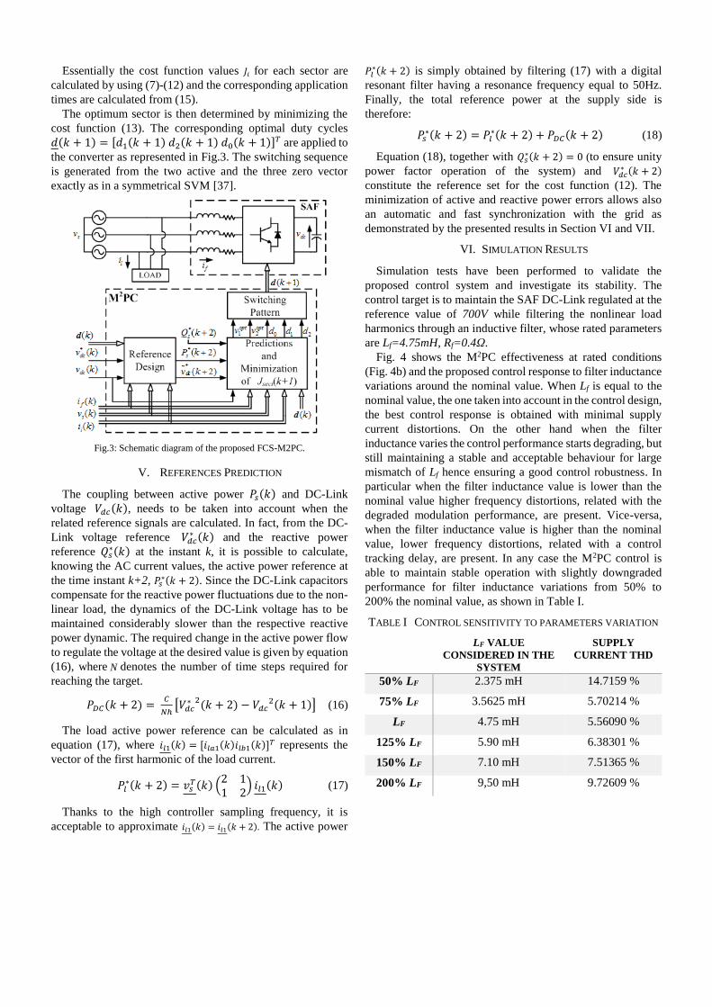
Fig. 4 shows the M2PC effectiveness at rated conditions
(Fig. 4b) and the proposed control response to filter inductance
variations around the nominal value. When Lf is equal to the
nominal value, the one taken into account in the control design,
the best control response is obtained with minimal supply
current distortions. On the other hand when the filter
inductance varies the control performance starts degrading, but
still maintaining a stable and acceptable behaviour for large
mismatch of Lf hence ensuring a good control robustness. In
particular when the filter inductance value is lower than the
nominal value higher frequency distortions, related with the
degraded modulation performance, are present. Vice-versa,
when the filter inductance value is higher than the nominal
value, lower frequency distortions, related with a control
tracking delay, are present. In any case the M2PC control is
able to maintain stable operation with slightly downgraded
performance for filter inductance variations from 50% to
200% the nominal value, as shown in Table I.
TABLE I CONTROL SENSITIVITY TO PARAMETERS VARIATION
LF VALUE
CONSIDERED IN THE
SYSTEM
SUPPLY
CURRENT THD
50% LF 2.375 mH 14.7159 %
75% LF 3.5625 mH 5.70214 %
LF 4.75 mH 5.56090 %
125% LF 5.90 mH 6.38301 %
150% LF 7.10 mH 7.51365 %
200% LF 9,50 mH 9.72609 %
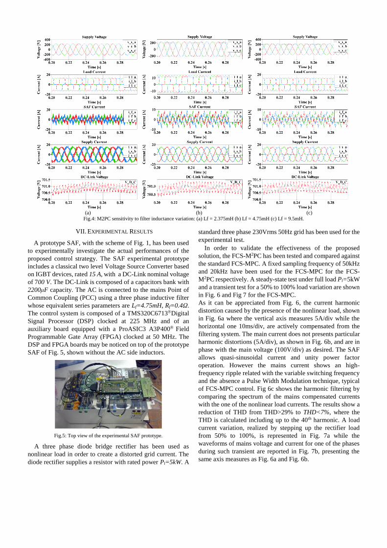
(a) (b) (c)
Fig.4: M2PC sensitivity to filter inductance variation: (a) Lf = 2.375mH (b) Lf = 4.75mH (c) Lf = 9.5mH.
VII. EXPERIMENTAL RESULTS
A prototype SAF, with the scheme of Fig. 1, has been used
to experimentally investigate the actual performances of the
proposed control strategy. The SAF experimental prototype
includes a classical two level Voltage Source Converter based
on IGBT devices, rated 15 A, with a DC-Link nominal voltage
of 700 V. The DC-Link is composed of a capacitors bank with
2200μF capacity. The AC is connected to the mains Point of
Common Coupling (PCC) using a three phase inductive filter
whose equivalent series parameters are Lf=4.75mH, Rf=0.4Ω.
The control system is composed of a TMS320C6713Digital
Signal Processor (DSP) clocked at 225 MHz and of an
auxiliary board equipped with a ProASIC3 A3P400 Field
Programmable Gate Array (FPGA) clocked at 50 MHz. The
DSP and FPGA boards may be noticed on top of the prototype
SAF of Fig. 5, shown without the AC side inductors.
Fig.5: Top view of the experimental SAF prototype.
A three phase diode bridge rectifier has been used as
nonlinear load in order to create a distorted grid current. The
diode rectifier supplies a resistor with rated power Pl=5kW. A
standard three phase 230Vrms 50Hz grid has been used for the
experimental test.
In order to validate the effectiveness of the proposed
solution, the FCS-M2PC has been tested and compared against
the standard FCS-MPC. A fixed sampling frequency of 50kHz
and 20kHz have been used for the FCS-MPC for the FCS-
M2PC respectively. A steady-state test under full load Pl=5kW
and a transient test for a 50% to 100% load variation are shown
in Fig. 6 and Fig 7 for the FCS-MPC.
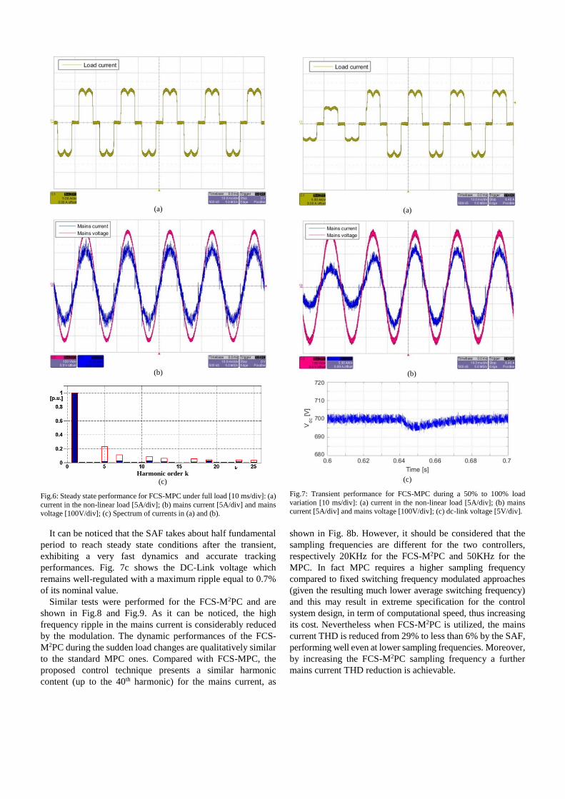
As it can be appreciated from Fig. 6, the current harmonic
distortion caused by the presence of the nonlinear load, shown
in Fig. 6a where the vertical axis measures 5A/div while the
horizontal one 10ms/div, are actively compensated from the
filtering system. The main current does not presents particular
harmonic distortions (5A/div), as shown in Fig. 6b, and are in
phase with the main voltage (100V/div) as desired. The SAF
allows quasi-sinusoidal current and unity power factor
operation. However the mains current shows an high-
frequency ripple related with the variable switching frequency
and the absence a Pulse Width Modulation technique, typical
of FCS-MPC control. Fig 6c shows the harmonic filtering by
comparing the spectrum of the mains compensated currents
with the one of the nonlinear load currents. The results show a
reduction of THD from THD>29% to THD<7%, where the
THD is calculated including up to the 40th harmonic. A load
current variation, realized by stepping up the rectifier load
from 50% to 100%, is represented in Fig. 7a while the
waveforms of mains voltage and current for one of the phases
during such transient are reported in Fig. 7b, presenting the
same axis measures as Fig. 6a and Fig. 6b.
(a)
(b)
Harmonic order k
(c)
Fig.6: Steady state performance for FCS-MPC under full load [10 ms/div]: (a)
current in the non-linear load [5A/div]; (b) mains current [5A/div] and mains voltage [100V/div]; (c) Spectrum of currents in (a) and (b).
(a)
(b)
(c)
Fig.7: Transient performance for FCS-MPC during a 50% to 100% load
variation [10 ms/div]: (a) current in the non-linear load [5A/div]; (b) mains current [5A/div] and mains voltage [100V/div]; (c) dc-link voltage [5V/div].
It can be noticed that the SAF takes about half fundamental
period to reach steady state conditions after the transient,
exhibiting a very fast dynamics and accurate tracking
performances. Fig. 7c shows the DC-Link voltage which
remains well-regulated with a maximum ripple equal to 0.7%
of its nominal value.
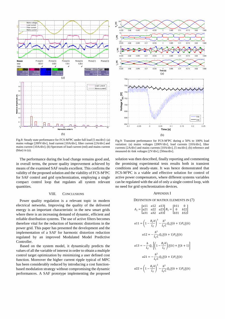
Similar tests were performed for the FCS-M2PC and are
shown in Fig.8 and Fig.9. As it can be noticed, the high
frequency ripple in the mains current is considerably reduced
by the modulation. The dynamic performances of the FCS-
M2PC during the sudden load changes are qualitatively similar
to the standard MPC ones. Compared with FCS-MPC, the
proposed control technique presents a similar harmonic
content (up to the 40th harmonic) for the mains current, as
shown in Fig. 8b. However, it should be considered that the
sampling frequencies are different for the two controllers,
respectively 20KHz for the FCS-M2PC and 50KHz for the
MPC. In fact MPC requires a higher sampling frequency
compared to fixed switching frequency modulated approaches
(given the resulting much lower average switching frequency)
and this may result in extreme specification for the control
system design, in term of computational speed, thus increasing
its cost. Nevertheless when FCS-M2PC is utilized, the mains
current THD is reduced from 29% to less than 6% by the SAF,
performing well even at lower sampling frequencies. Moreover,
by increasing the FCS-M2PC sampling frequency a further
mains current THD reduction is achievable.
(a)
(b)
Fig.8: Steady state performance for FCS-M2PC under full load [5 ms/div]: (a)
mains voltage [200V/div], load current [10A/div], filter current [2A/div] and mains current [10A/div]; (b) Spectrum of load current (red) and mains current
(blue) in (a).
(a)
(b)
Fig.9: Transient performance for FCS-M2PC during a 50% to 100% load
variation: (a) mains voltages [200V/div], load currents [10A/div], filter currents [2A/div] and mains currents [10A/div], [5 ms/div]; (b) reference and
measured dc-link voltages [2V/div], [50ms/div].
The performance during the load change remains good and,
in overall terms, the power quality improvement achieved by
means of the examined SAF results excellent. This confirms the
validity of the proposed solution and the viability of FCS-M2PC
for SAF control and grid synchronization, employing a single
compact control loop that regulates all system relevant
quantities.
VIII. CONCLUSIONS
Power quality regulation is a relevant topic in modern
electrical networks. Improving the quality of the delivered
energy is an important characteristic in the new smart grids
where there is an increasing demand of dynamic, efficient and
reliable distribution systems. The use of active filters becomes
therefore vital for the reduction of harmonic distortions in the
power grid. This paper has presented the development and the
implementation of a SAF for harmonic distortion reduction
regulated by an improved Modulated Model Predictive
Controller.
Based on the system model, it dynamically predicts the
values of all the variable of interest in order to obtain a multiple
control target optimization by minimizing a user defined cost
function. Moreover the higher current ripple typical of MPC
has been considerably reduced by introducing a cost function-
based modulation strategy without compromising the dynamic
performances. A SAF prototype implementing the proposed
solution was then described, finally reporting and commenting
the promising experimental tests results both in transient
conditions and steady-state. It was hence demonstrated that
FCS-M2PC is a viable and effective solution for control of
active power compensators, where different systems variables
can be regulated with the aid of only a single control loop, with
no need for grid synchronization devices.
APPENDIX I
DEFINITION OF MATRIX ELEMENTS IN (7)
𝐴2 = [𝑎11 𝑎12 𝑎13𝑎21 𝑎22 𝑎23𝑎31 𝑎32 𝑎33
]𝐵2 = [𝑏11 00 𝑏22𝑏31 𝑏32
]
𝑎11 = (1 −𝑅𝑓ℎ
𝐿𝑓)
2
−ℎ2
𝐿𝑓𝐶𝑄1𝑆(𝑘 + 1)𝑃1𝑆(𝑘)
𝑎12 = −ℎ2
𝐿𝑓𝐶𝑄1𝑆(𝑘 + 1)𝑃2𝑆(𝑘)
𝑎13 = −ℎ
𝐿𝑓𝑄1 [(1 −
𝑅𝑓ℎ
𝐿𝑓)𝑆(𝑘) + 𝑆(𝑘 + 1)]
𝑎21 = −ℎ2
𝐿𝑓𝐶𝑄2𝑆(𝑘 + 1)𝑃1𝑆(𝑘)
𝑎22 = (1 −𝑅𝑓ℎ
𝐿𝑓)
2
−ℎ2
𝐿𝑓𝐶𝑄2𝑆(𝑘 + 1)𝑃2𝑆(𝑘)
𝑎23 = −ℎ
𝐿𝑓𝑄2 [(1 −
𝑅𝑓ℎ
𝐿𝑓)𝑆(𝑘) + 𝑆(𝑘 + 1)]
𝑎31 =ℎ
𝐶𝑃1 [𝑆(𝑘) + (1 −
𝑅𝑓ℎ
𝐿𝑓)𝑆(𝑘 + 1)]
𝑎32 =ℎ
𝐶𝑃2 [𝑆(𝑘) + (1 −
𝑅𝑓ℎ
𝐿𝑓)𝑆(𝑘 + 1)]
𝑎33 = 1 −ℎ2
𝐿𝑓𝐶[𝑃1𝑆(𝑘 + 1)𝑄1𝑆(𝑘) + 𝑃2𝑆(𝑘 + 1)𝑄2𝑆(𝑘)]
𝑏11 = 𝑏22 =ℎ(2𝐿𝑓 − 𝑅𝑓ℎ)
𝐿𝑓2 𝑏31 =
ℎ2
𝐿𝑓𝐶𝑃1𝑆(𝑘 + 1) 𝑏32 =
ℎ2
𝐿𝑓𝐶𝑃2𝑆(𝑘 + 1)
REFERENCES
[1] P. Salmeron and S. P. Litran, “Improvement of the Electric Power Quality Using Series Active and Shunt Passive Filters,” IEEE Trans. Power Del., vol. 25, no. 2, pp. 1058–1067, 2010.
[2] H. Johal and D. Divan, “Design Considerations for Series-Connected Distributed FACTS Converters,” IEEE Trans. Ind. Appl., vol. 43, no. 6, pp. 1609–1618, 2007.
[3] D. Divan and H. Johal, “Distributed FACTS—A New Concept for Realizing Grid Power Flow Control,” IEEE Trans. Power Electron., vol. 22, no. 6, p. 2253, 2007.
[4] B. Singh, K. Al-Haddad, and A. Chandra, “A review of active filters for power quality improvement,” IEEE Trans. Ind. Electron., vol. 46, no. 5, pp. 960–971, 1999.
[5] M. L. Heldwein, H. Ertl, J. Biela, D. Das, R. P. Kandula, J. A. Munoz, D. Divan, R. G. Harley, and J. E. Schatz, “An Integrated Controllable Network Transformer—Hybrid Active Filter System,” IEEE Trans. Ind. Appl., vol. 51, no. 2, pp. 1692–1701, 2015.
[6] S. W. Mohod and M. V. Aware, “A STATCOM-Control Scheme for Grid Connected Wind Energy System for Power Quality Improvement,” IEEE Syst. J., vol. 4, no. 3, pp. 346–352, 2010.
[7] S. Wenchao and A. Q. Huang, “Fault-Tolerant Design and Control Strategy for Cascaded H-Bridge Multilevel Converter-Based STATCOM,” IEEE Trans. Ind. Electron., vol. 57, no. 8, pp. 2700–2708, 2010.
[8] A. Hamadi, S. Rahmani, and K. Al-Haddad, “A Hybrid Passive Filter Configuration for VAR Control and Harmonic Compensation,” IEEE Trans. Ind. Electron., vol. 57, no. 7, pp. 2419–2434, 2010.
[9] R. C. Dugan, M. F. McGranaghan, and H. W. Beaty, Electrical power systems quality. McGraw-Hill, 1996.
[10] H. Akagi, “The state-of-the-Art of Active Filters for Power Conditioning,” Eur. Conf. Power Electron. Appl., p. 15, 2005.
[11] S. Buso, L. Malesani, and P. Mattavelli, “Comparison of Current Control Techniques for Active Filter Applications,” IEEE Trans. Ind. Electron., vol. 45, no. 5, pp. 722–729, 1998.
[12] P. Jintakosonwit, H. Fujita, and H. Akagi, “Control and performance of a fully-digital-controlled shunt active filter for installation on a power distribution system,” IEEE Trans. Power Electron., vol. 17, no. 1, pp. 132–140, 2002.
[13] D. N. Zmood, D. G. Holmes, and G. H. Bode, “Frequency-domain analysis of three-phase linear current regulators,” IEEE Trans. Ind. Appl., vol. 37, no. 2, pp. 601–610, 2001.
[14] E. H. J.M., C.-M. J., F. J.R., and G.-G. R., “A synchronous Reference Frame Robust Predictive Current Control for Three-Phase Grid-Connected Inverters,” IEEE Trans. Ind. Electron., vol. 57, no. 3, pp. 954–962, 2010.
[15] P. Mattavelli, “A Closed Loop Selective Harmonic Compensation for Active Filters,” IEEE Trans. Ind. Appl., vol. 37, no. 1, pp. 81–89, 2001.
[16] K. H. Kwan, P. L. So, and Y. C. Chu, “A harmonic selective unified power quality conditioner using MVR with Kalman filters,” Int. Power Eng. Conf., pp. 332–337, 2007.
[17] L. Malesani, P. Mattavelli, and S. Buso, “Robust dead-beat current control for PWM rectifiers and active filters,” IEEE Trans. Ind. Appl., vol. 35, no. 3, pp. 613–620, 1998.
[18] S. Kouro, P. Cortés, R. Vargas, U. Ammann, and J. Rodríguez, “Model predictive control—A simple and powerful method to control power converters,” IEEE Trans. Ind. Electron., vol. 56, no. 6, pp. 1826–1838, 2009.
[19] J. Rodríguez and M. P. Kazmierkowski, “State of the Art of Finite Control Set Model Predictive Control in Power Electronics,” IEEE Trans. Ind. Informat., vol. 9, no. 2, pp. 1003–1016, 2013.
[20] R. P. Aguilera, P. Lezana, and D. E. Quevedo, “Finite-Control-Set Model Predictive Control With Improved Steady-State Performance,” IEEE Trans. Ind. Informat., vol. 9, no. 2, pp. 658–667, May 2013.
[21] L. Tarisciotti, P. Zanchetta, A. Watson, J. C. Clare, S. Member, M. Degano, and S. Bifaretti, “Modulated Model Predictive Control for a Three-Phase Active Rectifier,” IEEE Trans. Ind. Appl., vol. 51, no. 2, pp. 1610–1620, 2015.
[22] M. Rivera, C. Rojas, J. Rodríguez, P. Wheeler, B. Wu, and J. R. Espinoza, “Predictive Current Control With Input Filter Resonance Mitigation for a Direct Matrix Converter,” IEEE Trans. Power Electron., vol. 26, no. 10, pp. 2794–2803, 2011.
[23] M. Rivera, L. Tarisciotti, P. Zanchetta, and P. Wheeler, “Predictive control of an indirect matrix converter operating at fixed switching frequency and without weighting factors,” IEEE Int. Symp. Ind. Electron., pp. 2163–5145, 2015.
[24] Z. Zhang, H. Fang, and R. Kennel, “Fully FPGA based direct model predictive power control for grid-tied AFEs with improved performance,” 41st Annu. Conf. IEEE Ind. Electron. Soc., pp. 3881–3886, 2015.
[25] B. Arif, L. Tarisciotti, P. Zanchetta, J. C. Clare, and M. Degano, “Grid Parameter Estimation Using Model Predictive Direct Power Control,” IEEE Trans. Ind. Appl., vol. 51, no. 6, pp. 4614–4622, 2015.
[26] L. Rovere, A. Formentini, A. Gaeta, P. Zanchetta, and M. Marchesoni, “Sensorless Finite Control Set Model Predictive Control for IPMSM Drives,” IEEE Trans. Ind. Electron., vol. 63, no. 9, pp. 5921–5931, 2016.
[27] A. Formentini, L. de Lillo, M. Marchesoni, A. Trentin, P. Wheeler, and P. Zanchetta, “A new mains voltage observer for PMSM drives fed by matrix converters,” in EPE, 2014, pp. 1–10.
[28] E. Fuentes, D. Kalise, J. Rodríguez, and R. M. Kennel, “Cascade-Free Predictive Speed Control for Electrical Drives,” IEEE Trans. Ind. Electron., vol. 61, no. 5, pp. 2176–2184, 2014.
[29] M. Preindl and S. Bolognani, “Model Predictive Direct Speed Control with Finite Control Set of PMSM Drive Systems,” IEEE Trans. Power Electron., vol. 28, no. 2, pp. 1007–1015, 2013.
[30] A. Formentini, A. Trentin, M. Marchesoni, P. Zanchetta, and P. Wheeler, “Speed Finite Control Set Model Predictive Control of a PMSM Fed by Matrix Converter,” IEEE Trans. Ind. Electron., vol. 62, no. 11, pp. 6786–6796, 2015.
[31] L. Tarisciotti, P. Zanchetta, A. Watson, P. Wheeler, J. C. Clare, and S. Bifaretti, “Multiobjective Modulated Model Predictive Control for a Multilevel Solid-State Transformer,” IEEE Trans. Ind. Appl., vol. 51, no. 5, pp. 4051–4060, 2015.
[32] L. Tarisciotti, P. Zanchetta, A. J. Watson, J. C. Clare, S. Bifaretti, and M. Rivera, “A new Predictive Control method for cascaded multilevel converters with intrinsic modulation scheme,” IEEE Annu. Conf. Ind. Electron., pp. 5764–5769, 2013.
[33] L. Tarisciotti, P. Zanchetta, A. Watson, J. Clare, and S. Bifaretti, “Modulated Model Predictive Control for a 7-Level Cascaded H-Bridge back-to-back Converter,” IEEE Trans. Ind. Electron., vol. 61, no. 10, pp. 5375 – 5383, 2014.
[34] M. Vijayagopal, L. Empringham, L. De Lillo, L. Tarisciotti, P. Zanchetta, and P. Wheeler, “Current control and reactive power minimization of a direct matrix converter induction motor drive with Modulated Model Predictive Control,” IEEE Int. Symp. Predict. Control Electr. Drives Power Electron., pp. 4315–4321, 2015.
[35] M. Vijayagopal, L. Empringham, L. De Lillo, L. Tarisciotti, P. Zanchetta, and P. Wheeler, “Control of a Direct Matrix Converter Induction Motor Drive with Modulated Model Predictive Control,” IEEE Energy Convers. Congr. Expo., pp. 4315–4321, 2015.
[36] R. Rabbeni, L. Tarisciotti, A. Gaeta, A. Formentini, P. Zanchetta, M. Pucci, M. Degano, and M. Rivera, “Finite states modulated model predictive control for active power filtering systems,” IEEE Energy Convers. Congr. Expo., pp. 1556–1562, 2015.
[37] L. Tarisciotti, P. Zanchetta, A. J. Watson, J. C. Clare, M. Degano, and S. Bifaretti, “Modulated Model Predictve Control (M2PC) for a 3-Phase Active Front-End,” in IEEE Energy Conversion Congress and Exposition (ECCE), 2013, pp. 1062–1069.

Luca Tarisciotti (S’12-M’15) received the Master’s degree in electronic engineering from
The University of Rome "Tor Vergata" in 2009
and his Ph.D. degree in Electrical and Electronic
Engineering from the PEMC group, University
of Nottingham in 2015. He is currently working
as Research Fellow at the University of Nottingham, UK. His research interests includes
matrix converters, DC/DC converters, multilevel
converters, advanced modulation schemes, and advanced power converter control.
Andrea Formentini was born in Genova, Italy, in 1985. He received the M.S. degree in
computer engineering and the PhD degree in
electrical engineering from the University of Genova, Genova, in 2010 and 2014 respectively.
He is currently working as research fellow in the
Power Electronics, Machines and Control Group, University of Nottingham. His research
interests include control systems applied to
electrical machine drives and power converters.
Alberto Gaeta (S’ 08) received the M.S. and
Ph.D degrees in electrical engineering from the
University of Catania, Catania, Italy, in 2008 and
2011, respectively. From 2013 to 2015 he joined
the Power Electronics and Machine Control Group at the University of Nottingham.
Currently he works as a consultant for several
comnpanies. He is a member of the IEEE Industrial Electronics, IEEE Industry
Applications, IEEE Power Electronics Societies.
His research interests include power electronics and high performance drives, with particular attention to predictive, fault tolerant and sensorless control
techniques.
Marco Degano (S’03–M’07) received the 5
years Laurea Degree in Electronic Engineering from the Universita' degli studi di Udine (Italy)
in April 2004. Since February 2008 he joined the
Power Electronics Machines and Control (PEMC) research group at the University of
Nottingham starting first as a visiting research
fellow within the Marie Curie program, then in
October 2012 he received his PhD degree in
Electrical and Electronic Engineering; he is
currently a research fellow. His current research interests are in the field of power electronic,
especially for aerospace.
Pericle Zanchetta (M’00–SM’15) received his
Master degree in Electronic Engineering and his
Ph.D. in Electrical Engineering from the Technical University of Bari (Italy) in 1994 and
1998 respectively. In 1998 he became Assistant
Professor of Power Electronics at the same University. In 2001 he became lecturer in control
of power electronics systems in the PEMC
research group at the University of Nottingham – UK, where he is now Professor in Control of
Power Electronics systems. He has published
over 220 peer reviewed papers; he is Chair of the IAS Industrial Power Converter Committee (IPCC) and associate editor for
the IEEE transactions on Industry applications and IEEE Transaction on
industrial informatics. He is member of the European Power Electronics (EPE)
Executive Council. His general research interests are in the field of Power
Electronics, Power Quality, Renewable energy systems and Control.
Marcello Pucci (M’03–SM’11) received his “laurea” degree in Electrical Engineering from
the University of Palermo (Italy) in 1997 and the
Ph.D. degree in Electrical Engineering in 2002
from the same University. In 2000 he has been
an host student at the Institut of Automatic
Control of the Technical University of Braunschweig, Germany, working in the field of
control of AC machines, with a grant from
DAAD (Deutscher Akademischer Austauscdienst – German Academic Exchange
Service). From 2001 to 2007 he has been a
researcher and since 2008 he has been a senior researcher at the Section of Palermo of I.S.S.I.A.-C.N.R. (Institute on Intelligent Systems for the
Automation), Italy. He serves as an associate editor of the IEEE Transactions
on Industrial Electronics and IEEE Transactions on Industry Applications. He is a member of the Editorial Board of the "Journal of Electrical Systems". His
current research interests are electrical machines, control, diagnosis and
identification techniques of electrical drives, intelligent control and power converters. He is a senior member of the IEEE.
Roberto Rabbeni was born in Petralia Sottana, Italy, in 1987. He received the Master’s degree
in automation engineering from the University of
Palermo, Palermo, Italy, in 2013, where he is
currently working toward the Ph.D. degree in
system and control engineering in the
Department of Energy, Information Engineering and Mathematical Model. His research interests
focus on the development of feedback control
algorithms for nonlinear dynamical systems, identification techniques, and estimation of
dynamical systems. He is also interested in
applications of control of power converters, electrical drives, and mechanical systems.
Marco Rivera (S’09–M’11) received his B.Sc.in Electronics Engineering and M.Sc. in Electrical Engineering from the Universidad de Concepcion, Chile in 2007 and 2008, respectively. He recieved his Ph.D. degree at the Department of Electronics Engineering, Universidad Tecnica Federico Santa Maria (UTFSM), in Valparaiso, Chile, in 2011. He is currently Associate Professor in the Department of Industrial Technologies at Universidad de Talca, Curico, Chile. His main research areas are digital control applied to power
electronics, matrix converters, predictive control and control of power converters for renewable energy applications.