Embed Size (px)
Citation preview
STRONGINTERNATIONALa division of Ballantyne of Omaha, Inc.
4350 McKinley StreetOmaha, Nebraska 68112 USATel 402/453-4444 • Fax 402/453-7238
Model PR1014 (Cinema)Model PR1020 (Studio)
Model PR1030 (Fwd/Rev)


TABLE OF CONTENTS
PREFACE 1FIGURE 1 3FIGURE 2 4INSTALLATION
Unpacking 5Mounting 5Lamphouse Alignment 6Framing Lamp Transformer 6Picture Changeover 6Lens Installation 6Lamphouse Light Shield 7
START-UP PROCEDURESInitial Oiling 8Threading 9Initial Operation 10
MAINTENANCELubrication 11Sprockets 11Pad Rollers 11Fastening Hardware 11Film Gate 11Film Trap 11Overall Appearance 11
FIGURE 3 12FIGURE 4 13FIGURE 5 14FIGURE 6 15
i

TABLE OF CONTENTS (continued)
ADJUSTMENTS & REPLACEMENTSIntermittent Shoe Replacement 16Intermittent Shoe Alignment 16Film Gate Closure 16Film Trap 16Film Trap Lateral Rollers 17Pressure Strap Replacement 17Studio Guide Replacement 17Gear Compartment Cover 17Intermittent Movement 17Framing Lamp 19Oil Pump Feed Reversal 19Film Sprocket Assemblies 19Pad Roller Assemblies 20Shutter Replacement 20Shutter Timing 21
STRONG INTERNATIONALa division of Ballantyne of Omaha, Inc.
Engineering/SalesJuly 1999
ii
PREFACE
THE SIMPLEX 35 PROJECTOR, Model 1014, combining rugged construction withease of operation, provides theatre owners with a superior mechanism, engineered to the high standardsset for all Strong International products. The following design features illustrate why the Simplex 35Projector is able to provide continuously excellent performance throughout its long operating life:
UNIT DESIGN
Unit method of design simplifies part replacement and maintenance. All units may be quicklyremoved and replaced. Components within a particular unit are just as easily handled.
SOUNDHEAD
Although the Simplex 35 Projector was designed for use with the Simplex 5-Star Soundhead,other soundheads may be used without loss of quality.
MAIN DRIVE AND IDLER GEAR ASSEMBLIES
The main drive gear and idler assemblies are easily installed, insure proper driving from thesoundhead, and are adjustable.
OPTICS
A conical shutter, positioned close to the picture aperture, provides very high light efficiency.Optical design is compatible to modern xenon lamphouse systems.
LENS BARREL
The lens barrel will accommodate projection lenses up to four inches in diameter. Lens reducersare supplied to mount currently available 2-25/32" lenses. An easily accessible adjusting knob permitsconcise focusing.
FILM COMPARTMENT
The roomy film compartment permits ease of threading and cleaning. The film compartmentdoor swings open for easy access, and includes a threading light.
GEAR COMPARTMENT
The gear compartment has a removable cover, rounded corners, and an enameled finish whichfacilitates cleaning.
1
MAIN FRAME
The main frame forms a single unit with the base, top, and front that is noteworthy for itssimplicity and strength.
FILM SPROCKETS
The upper feed, and lower holdback sprockets, having twenty-four teeth each, reduce shaftspeeds to prolong operating life, permit smoother wrap-around, and lessen the danger of splice break-age. Exclusive use of VKF® sprockets insures minimum film wear. The pad rollers are made of durable,lightweight nylon.
FILM TRAP
The film trap conforms to the curved film gate, and accommodates slip-in aperture plates. Thetrap is easily removed and replaced for routine cleaning and maintenance.
FILM GATE
The curved gate, together with the film trap, controls the movement of the film past the apertureby five different tension settings. Gate curvature provides compensation for heat-induced warping ofthe film at the aperture, thus insuring a sharper image on the screen. The gate is easily removed, cleaned,and replaced.
INTERMITTENT MOVEMENT
The intermittent movement features a webbed starwheel for high strength, long life, and positiveregistration. The VKF| intermittent sprocket is adjustable, making absolute alignment possible.
LUBRICATION
A Spray-O-Matic Lubrication System, with a gear-driven oil pump, completely lubricates allmoving components. The moving parts inside the gear compartment are visible through the glass panelin the full-vision oil-sealed cover. The intermittent movement lubricates itself by pump action, and theSpray-O-Matic system. An oil level sight glass in the film compartment permits a visual check of the oillevel.
COOLING
The Simplex 35 Projector includes a standard air cooled trap. Water cooled traps may be or-dered as an option, factory installed or field retrofit.
VKF® is a registered trademark of LaVezzi Precision, Inc. Elmhurst, Illinois
2

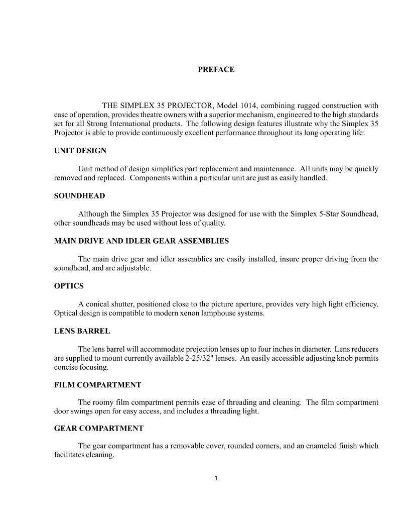
SightGlass
FocusAdjustingKnob
LensBarrel
ShutterAdjustingKnob
Electric ChangeoverDevice
ThreadingLight SwitchFraming
Knob
ShutterGuard
Shutter GuardThumb Nut
FIGURE 1
3

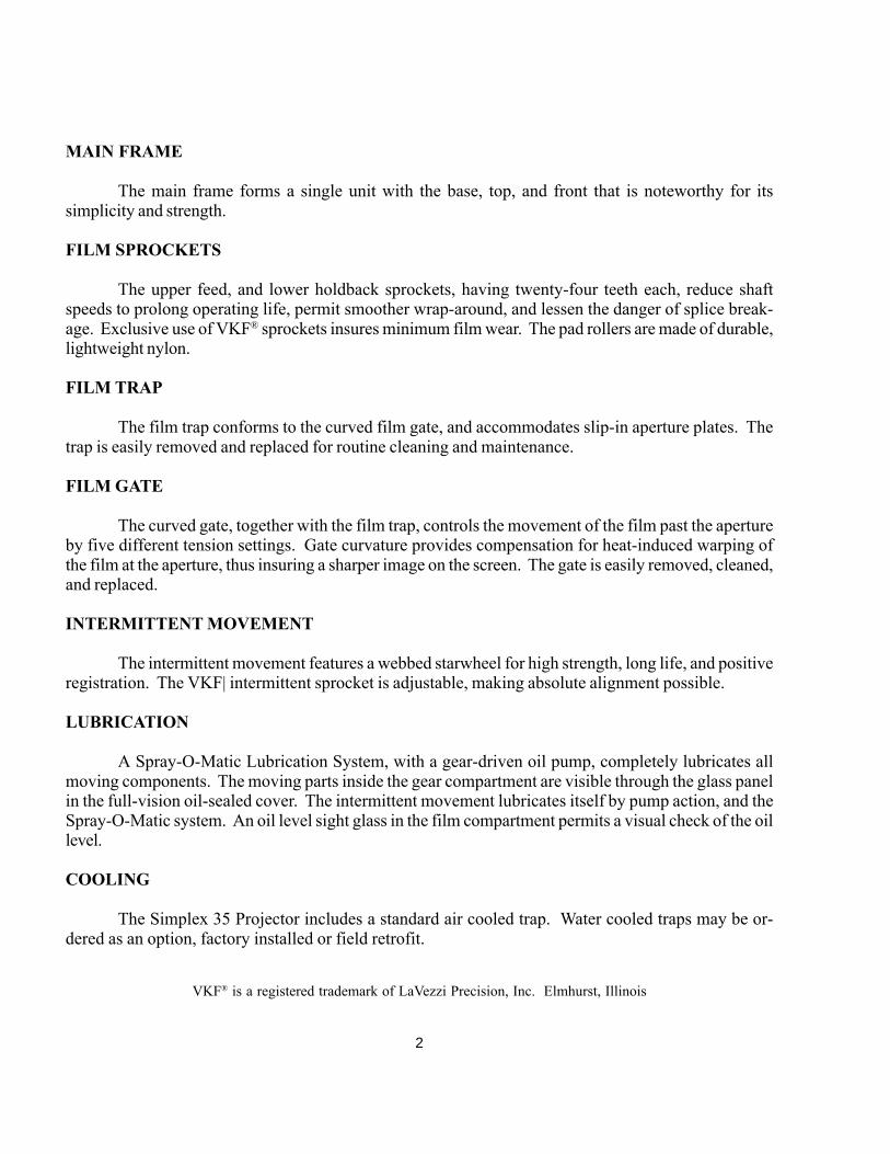
Shutter AdjustingKnob
Film TrapTensionAdjustment
Upper FilmStripper
Feed Sprocket& Pad RollerAssembly
ThreadingLight
Film Gate
LensClampingKnob
Lens HolderLock Screw
Oil LevelSight Glass
Gate OpeningLever
Holdback Sprocket& Pad RollerAssembly
Film TrapWater Lines*
Gate ReleaseLever
IntermittentSprocket
Film Trap
FIGURE 2
* Water Cooled Film Trap OPTIONAL
4
INSTALLATION
EACH SIMPLEX 35 PROJECTOR is carefully inspected and film tested before leavingthe factory. Carefully inspect the unit on receipt for any shipping damage, and file any damage claimswith the carrier immediately. It is the responsibility of the consignee, not Strong International, to filesuch claims.
THE FOLLOWING RECOMMENDATIONS should be studied carefully prior to in-stallation. Your Strong International Dealer may wish to assist in installing those items supplied by him.
UNPACKING
The Simplex 35 Projector is shipped in a sturdy wooden crate. TOP and OPEN THIS SIDE aremarked on the carton. The projector is mounted to the base of the crate with (2) 3/8-16 hex headscrews. If shipped as an “All-In-One” system (including 5-Star soundhead), the soundhead is mountedto the base with (2) 5/16-18 hex head screws.
An accessory kit is shipped with each Simplex 35 Projector. The kit includes the following:
(1) Can Simplex Projector Oil (1) Framing Lamp Transformer(1) Oiler (2) Lens Reducers(1) Set Allen Wrenches (1) Aperture Plate, “Flat”
The tools and accessories are required for adjustments and maintenance after installation. Keep them ina secure location in the projection booth.
MOUNTING
When not shipped as an “All-In-One” system, the projector must be mounted to the soundhead,after the soundhead has been installed to the projection pedestal or console. See Soundhead Manual.
The projector mounting bar (P-2396) is shipped with the 5 Star Soundhead. Mount the bar tothe base of the projector using the (2) 3/8-16 socket head screws provided. Mount the projector to thetop of the soundhead with the mounting bar in the channel on the top of the soundhead casting. Attachthe mounting bar to the soundhead casting using the (2) 5/16-18 hex head screws and washers supplied.A slight degree of tolerance between the mounting bar and the soundhead casting permit positioning theprojector for smooth film feed between the projector and soundhead. When correctly positioned, se-curely tighten all mounting fasteners. Run the drive belt to the projector and tension the belt withsoundhead idler assembly.
5

LAMPHOUSE OPTICAL ALIGNMENT
Carefully follow the lamphouse manufacturer’s instructions regarding correct optical alignmentbetween the lamphouse and projector. The lamphouse is generally aligned to the projector aperture, butsome consoles require positioning the projector and soundhead to the optical center of the lamphouse.DO NOT alter the film path between the projector and soundhead in the course of these adjustments.DO NOT operate the lamphouse with the douser open unless the projector is running.
FRAMING/THREADING LAMP TRANSFORMER
Connect the (2) yellow leads of the transformer to the framing lamp leads running from the 90degree connector at the top of the projector on the shutter housing. Shield leads in flexible conduit asrequired. Supply 120 V.AC to the (2) black transformer leads. The framing light switches ON and OFFby means of the pushbutton switch above the film trap inside the film compartment. The threading lampswitch is on the outside of the film compartment door.
PICTURE CHANGEOVER
The Simplex 35 is normally supplied with either a G-2090 (“Zipper”) or G-9727 (Strong) 120V.AC picture changeover device. Connect the changeover leads as follows:
G-2090 G-9727
Blk - OPEN Blk - OPENBrn - CLOSE Red - CLOSEWht - COMMON Wht - COMMON
Grn - GROUND
NOTE: These changeover devices require a 120 V.AC pulse to operate. Connecting the changeover toa sustained 120 V.AC supply will destroy the electrical coil. Check carefully the instructions suppliedwith the automation controller or the (installer supplied) switching circuit.
PROJECTION LENSES
Open the film compartment door and loosen the lens locking knob below the lens barrel. Rotatethe focus knob to position it in mid-travel.
Locate the (2) lens reducers. The light shields are attached reversed (inside the lens reducer) forshipping. Remove the light shields. Install the lens reducer into the lens barrel engaging the pin in thelens reducer into the keyway in the lens barrel. Insert the “flat” lens into the reducer. In the course ofINITIAL OPERATION (following), move the lens inside the reducer to project the sharpest picture.Tighten the rear reducer set screw through the cut out at the rear of the lens barrel. Remove the lens and
6
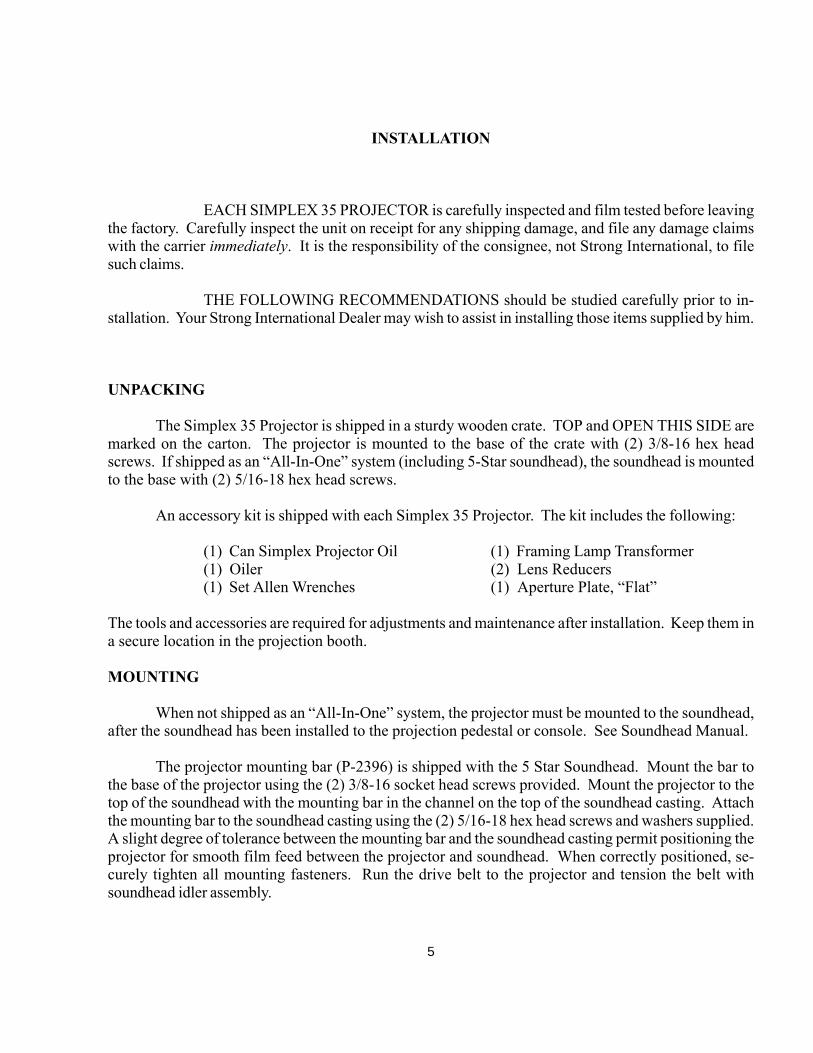
reducer, and tighten the front reducer set screw. Install the light shield to the rear of the lens reducer.Replace the lens and adapter into the lens barrel, and confirm the sharp projected picture. Repeat thisprocedure with the CinemaScope lens. When installing the CinemaScope lens and anamorphic adapter,check also the correct picture azimuth on the horizontal plane. When replacing lenses, make certainthat the pin is engaged in the keyway.
Additional lens reducers, if required for special applications, are available from your StrongInternational Dealer; order Part No. G-2156.
File the aperture plates to fit screen parameters. NOTE: The “flat” aperture plate is included inthe Accessory Kit.
LAMPHOUSE LIGHT SHIELD
Light shields, or nose cones, supplied by the lamphouse manufacturer, may be installed betweenthe projector shutter guard and the lamphouse snood. Make certain that the nose cone does not obstructthe rotation of the shutter. Trim or otherwise modify as required.
PROJECTION LENSES (continued)
7

START-UP PROCEDURES
ALL SIMPLEX PROJECTORS are carefully “run-in” at the factory prior to shipping.No “run-in” period at the installation site is required. Some gear whine may be noticed initially, butshould disappear after a few hours of operation.
INITIAL OILING
One quart of Simplex Projector Oil is included in the accessory kit supplied with new equipment.USE ONLY GENUINE SIMPLEX PROJECTOR OIL IN THE MECHANISM. Use of other lubri-cants may inhibit pump operation and damage moving parts. Additional oil is available through autho-rized Strong International Dealers; order Part No. R-0059 for (1) quart quantities.
DO NOT, at any time, operate the projector without oil.
Add oil through the filler located at the top of the gear compartment cover. The oil level isvisible through the sight glass inside the film compartment at the base of the main frame. When theprojector is level (0 degree projection angle), the correct oil level should be nearly to the top of the sightglass, with a small air bubble visible at the top.
As the machine is tilted to a downward projection angle, the air bubble will disappear. When themachine is started, the visible oil level will drop, indicating that the pump is drawing the oil from thereservoir and circulating it throughout the gear compartment.
If the machine is to be used in an extreme upward projection angle, the oil level will drop, andmay disappear when the machine is running. In this event, it is recommended to install a G-4350 Drive-In Oil Gauge Mounting Kit (see Parts Catalogue, Page 1-18). The main frame is drilled to accept use ofthis kit.
Rotate the soundhead flywheel by hand to turn the projector mechanism. It should turn freelyand smoothly. Start the projector motor and run for at least one minute. Check for an oil splash againstthe gear compartment cover glass.
8

THREADING
Threading the projector correctly is one of the operator’s most important duties. Careful atten-tion during this operation pays off in improved performances and long print life.
Rotate the framing knob (Item 7) to its center position(FRAME reading level, as shown). Using the soundhead fly-wheel, turn the mechanism by hand to place the intermittentsprocket (Item 9) in its “rest” position. In the “rest” position,the index mark (Item 10) will align with one of the paintedwhite index marks on the intermittent shaft collar when stop-ping after sprocket rotation.
Open the pad roller assemblies (Items 2, 5). Open the filmgate (Item 3) by moving the gate opening lever (Item 4) for-ward. The gate will lock in the open position (as shown).
At this time, it is advisable to dismount the film gate byremoving the (2) chrome knurled nuts. Use a clean, dry clothto wipe down all film bearing surfaces of the gate and trap(Item 13). Replace the film gate and nuts. This should beperformed at each threading operation.
Thread the film as illustrated. Engage first the intermittentsprocket (Item 9), and check for correct framing at the fram-ing aperture (Item 12). When correct, close the gate bytripping the gate release (Item 8). Form loops above andbelow the film gate as illustrated, and close the two padroller assemblies (Items 2, 5).
Turn the mechanism by hand to advance a few frames of film. Run fingers over each sprocket(Items 1, 6, 9) to insure that the sprocket teeth are centered in the film perforations, and the film iscentered in the sprockets. Check again the position of the film in the framing aperture (Item 12). Acorrect frame image in the framing aperture insures correct frame positioning in the picture aperture(Item 11). Use the framing knob (Item 7) to correct misframes.
Thread the soundhead as instructed in the soundhead manual. A slight degree of film tension isrequired above the feed sprocket (Item 1) and below the soundhead. This prevents the film from snap-ping on motor start.
CLEAN ALL FILM BEARING SURFACES BEFORE EACH THREADING OPERATION.Check all sprocket teeth for hooks or burrs; replace if required. Keep all pad rollers clean and operatingfreely.
to Soundhead
9
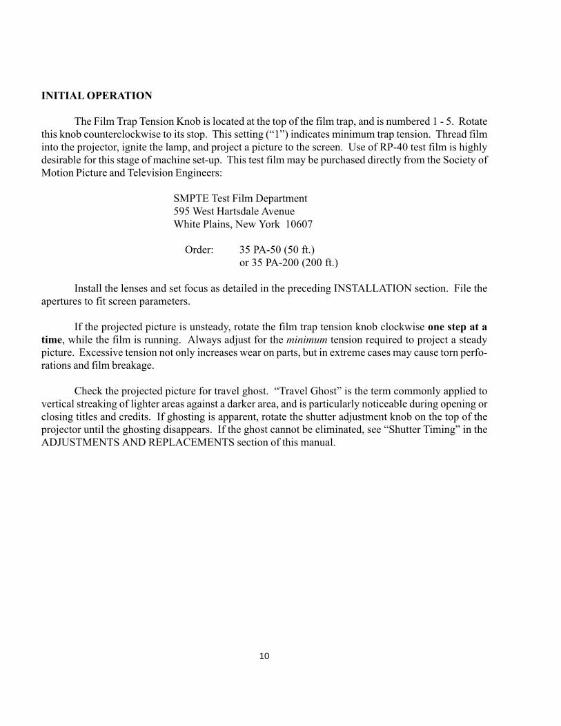
INITIAL OPERATION
The Film Trap Tension Knob is located at the top of the film trap, and is numbered 1 - 5. Rotatethis knob counterclockwise to its stop. This setting (“1”) indicates minimum trap tension. Thread filminto the projector, ignite the lamp, and project a picture to the screen. Use of RP-40 test film is highlydesirable for this stage of machine set-up. This test film may be purchased directly from the Society ofMotion Picture and Television Engineers:
SMPTE Test Film Department595 West Hartsdale AvenueWhite Plains, New York 10607
Order: 35 PA-50 (50 ft.)or 35 PA-200 (200 ft.)
Install the lenses and set focus as detailed in the preceding INSTALLATION section. File theapertures to fit screen parameters.
If the projected picture is unsteady, rotate the film trap tension knob clockwise one step at atime, while the film is running. Always adjust for the minimum tension required to project a steadypicture. Excessive tension not only increases wear on parts, but in extreme cases may cause torn perfo-rations and film breakage.
Check the projected picture for travel ghost. “Travel Ghost” is the term commonly applied tovertical streaking of lighter areas against a darker area, and is particularly noticeable during opening orclosing titles and credits. If ghosting is apparent, rotate the shutter adjustment knob on the top of theprojector until the ghosting disappears. If the ghost cannot be eliminated, see “Shutter Timing” in theADJUSTMENTS AND REPLACEMENTS section of this manual.
10
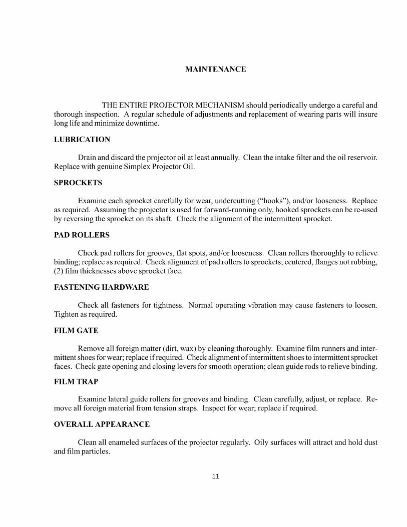
MAINTENANCE
THE ENTIRE PROJECTOR MECHANISM should periodically undergo a careful andthorough inspection. A regular schedule of adjustments and replacement of wearing parts will insurelong life and minimize downtime.
LUBRICATION
Drain and discard the projector oil at least annually. Clean the intake filter and the oil reservoir.Replace with genuine Simplex Projector Oil.
SPROCKETS
Examine each sprocket carefully for wear, undercutting (“hooks”), and/or looseness. Replaceas required. Assuming the projector is used for forward-running only, hooked sprockets can be re-usedby reversing the sprocket on its shaft. Check the alignment of the intermittent sprocket.
PAD ROLLERS
Check pad rollers for grooves, flat spots, and/or looseness. Clean rollers thoroughly to relievebinding; replace as required. Check alignment of pad rollers to sprockets; centered, flanges not rubbing,(2) film thicknesses above sprocket face.
FASTENING HARDWARE
Check all fasteners for tightness. Normal operating vibration may cause fasteners to loosen.Tighten as required.
FILM GATE
Remove all foreign matter (dirt, wax) by cleaning thoroughly. Examine film runners and inter-mittent shoes for wear; replace if required. Check alignment of intermittent shoes to intermittent sprocketfaces. Check gate opening and closing levers for smooth operation; clean guide rods to relieve binding.
FILM TRAP
Examine lateral guide rollers for grooves and binding. Clean carefully, adjust, or replace. Re-move all foreign material from tension straps. Inspect for wear; replace if required.
OVERALL APPEARANCE
Clean all enameled surfaces of the projector regularly. Oily surfaces will attract and hold dustand film particles.
11

FramingLight
Framing LightSwitch
Lateral GuideRoller
ShutterBlade
ChangeoverDouser
HeatShield
IntermittentOutboard Arm
IntermittentCollar
IntermittentMovement
IntermittentTensionShoe
TrapMountingScrew
FIGURE 3
12

Gear CompartmentCover
Cover FasteningNut
Shutter AdjustingKnob
ChangeoverLeads
Oil Fill Cup
FramingLightLeads
Film TrapWaterLines*
Framing KnobProjector DrivePulley
Oil Drain
Cover FasteningNut
FIGURE 4
* Water Cooled Film Trap OPTIONAL
13

Oil Slinger*
Upper FeedSprocket DriveGear
Upper FeedSprocketDriven Gear
Shutter ShaftDrive Gear
IntermittentDrive Gear
Main OilSupplyTube
Oil Pump Intake
Oil Pump Holdback SprocketDrive Gear
HoldbackSprocketDriven Gear
IntermittentFlywheel
Shutter DrivenGear
FIGURE 5
* Optional Governor Assembly not shown; see Simplex 35 Parts Catalogue
14

Oil Collector
Oil PumpOutlet
VerticalShaft
Vertical ShaftMounting Bracket
Oil PumpDriven Gear
Intermittent MovementRetaining Clamps andScrews
IntermediateFraming
Gear
IntermittentMovement
Oil Line
Shutter Shaft& FramingAssembly
FIGURE 6
15

ADJUSTMENTS AND REPLACEMENTS
REFER TO THIS SECTION in conjunction with following the instructions in the MAIN-TENANCE section. Conscientious maintenance and service of the Simplex 35 will insure many years ofexcellent performance.
ADJUSTMENTS are quickly accomplished, and replacements performed, as all unitsand components are readily removed. Adjustments and replacements described below may be per-formed by qualified projection booth personnel. Any elements of maintenance and service not detailedbelow should be referred to an authorized Strong International Dealer.
INTERMITTENT SHOE REPLACEMENT
Remove film gate. Dismount the shoe assembly by removing the mounting screw and leafspring. Replace worn components as required; check leaf spring for adequate tension. Reas-semble and remount.
INTERMITTENT SHOE ALIGNMENT
Place a straight edge across the outboard face of the intermittent sprocket and the outer face ofthe the tension shoe. Loosen the intermittent shoe assembly mounting screw, and slide the shoeassembly, as required, for exact alignment. Tighten mounting screw securely.
FILM GATE CLOSURE ADJUSTMENT
Remove the projection lens and dismount the film gate. Insert a pin or allen wrench in one of theholes in the tension collar on the operating lever shaft. Loosen the locking screw in the bottomof the operating lever assembly bracket, located through the casting below the tension collar.Rotate the collar counterclockwise using the pin or allen wrench until the next hole is aligned tothe locking screw. Tighten the locking screw. Repeat this adjustment procedure until properclosing tension is obtained.
FILM TRAP ASSEMBLY
Dismount the film gate and the shutter guard. Loosen the single captive film trap mountingscrew located between the trap tension knob and the aperture plate. Pull the trap assemblystraight out from the projector main frame. To replace, make certain that the contacting surfaceson both the main frame and the trap casting are clean. Slide the film trap in so that it registerswith the (2) dowel pins on the main frame. Securely tighten the captive screw. Check thealignment of the intermittent sprocket to the film trap (see INTERMITTENT MOVEMENTsection following).
16

FILM TRAP LATERAL GUIDE ROLLERS
Dismount film trap and associated components (see above). Loosen the (2) lateral roller pivotset screws. Slide the lateral roller pivots out of the casting and remove the lateral rollers andspring. Replace worn parts and reassemble. NOTE: For ease of threading, the spring-loadedlateral roller should be installed inboard. Position the fixed (outboard) lateral roller to the out-board edge of the film path. The horizontal positioning of the lateral rollers is determined bysliding the rollers and pivots in the trap casting. Center the rollers in this manner to the film path.Leave enough end play in the pivots to permit free rotation of the lateral rollers, and tighten the(2) pivot set screws.
PRESSURE STRAP REPLACEMENT
Dismount the film trap and associated components. Rotate the trap tension knob fully counter-clockwise to position “1”. Remove the (2) screws from each strap, and remove the straps.Replace with new straps and reassemble. NOTE: Reset trap tension with film projected (seeSTART-UP PROCEDURES).
STUDIO GUIDE REPLACEMENT
Remove the film gate and the projection lens. Remove the (2) flat socket head screws anddismount the studio guide. Position and install the replacement studio guide; replace the filmgate and projection lens.
GEAR COMPARTMENT COVER REMOVAL
Only when absolutely necessary, remove the gear compartment cover and only after the machinehas been at rest for at least (10) minutes to allow all oil to settle into the reservoir. Remove the(3) cover fastening thumb nuts. Make certain no foreign material deposits in the gear compart-ment while the cover is removed. Before replacing the cover, wipe all oil from the cover gasketand the mating surface on the projector main frame. Any oil remaining on these surfaces willprovide an oil seepage path after the cover is replaced. Tighten all (3) thumb nuts equally andfingertight, just enough to form an oil-tight seal.
INTERMITTENT MOVEMENT REPLACEMENT
1. Open the film gate. Rotate the framing knob (on the gear side) fully counterclockwise.2. Set the shutter adjusting knob in mid-position. To locate mid-position, rotate the knob to itsstop, and reverse 1-1/2 turns.3. Remove the gear compartment cover (see above).4. Rotate the vertical shaft until the intermittent drive gear mounting screw is visible. Removethe mounting screw and slide the gear downward.5. Loosen the (2) intermittent retaining clamp screws on the framing cam and position theclamps to clear the intermittent case.
17
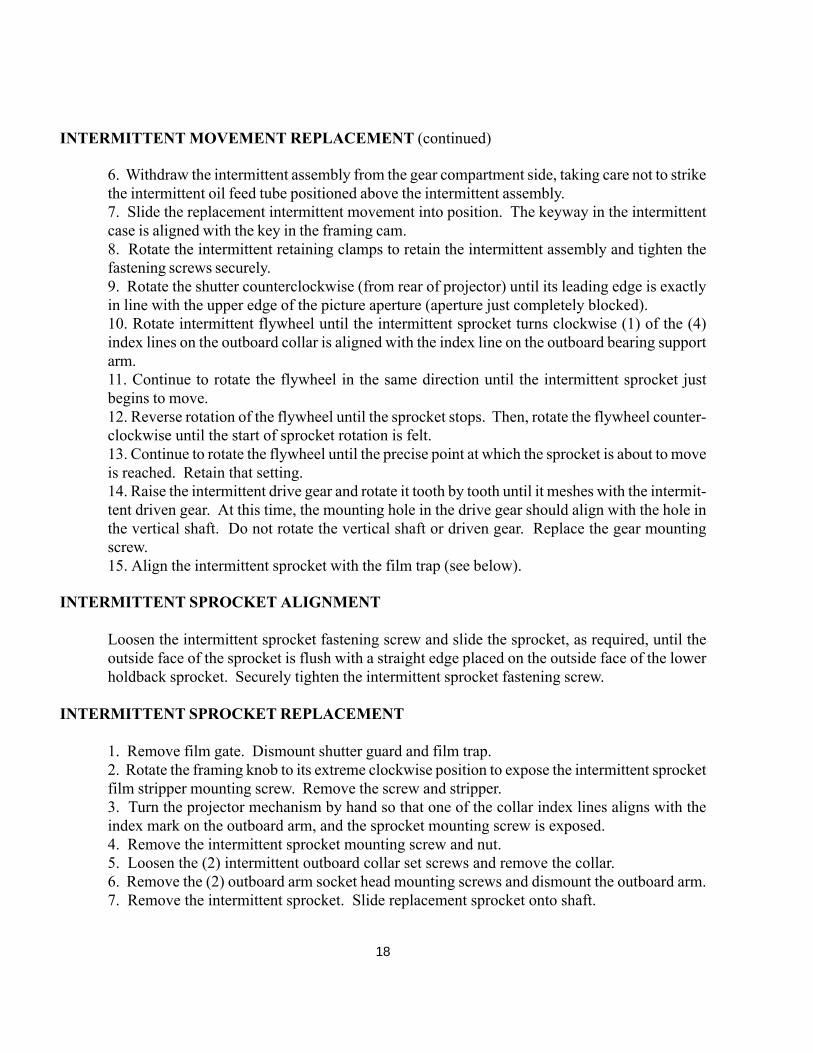
INTERMITTENT MOVEMENT REPLACEMENT (continued)
6. Withdraw the intermittent assembly from the gear compartment side, taking care not to strikethe intermittent oil feed tube positioned above the intermittent assembly.7. Slide the replacement intermittent movement into position. The keyway in the intermittentcase is aligned with the key in the framing cam.8. Rotate the intermittent retaining clamps to retain the intermittent assembly and tighten thefastening screws securely.9. Rotate the shutter counterclockwise (from rear of projector) until its leading edge is exactlyin line with the upper edge of the picture aperture (aperture just completely blocked).10. Rotate intermittent flywheel until the intermittent sprocket turns clockwise (1) of the (4)index lines on the outboard collar is aligned with the index line on the outboard bearing supportarm.11. Continue to rotate the flywheel in the same direction until the intermittent sprocket justbegins to move.12. Reverse rotation of the flywheel until the sprocket stops. Then, rotate the flywheel counter-clockwise until the start of sprocket rotation is felt.13. Continue to rotate the flywheel until the precise point at which the sprocket is about to moveis reached. Retain that setting.14. Raise the intermittent drive gear and rotate it tooth by tooth until it meshes with the intermit-tent driven gear. At this time, the mounting hole in the drive gear should align with the hole inthe vertical shaft. Do not rotate the vertical shaft or driven gear. Replace the gear mountingscrew.15. Align the intermittent sprocket with the film trap (see below).
INTERMITTENT SPROCKET ALIGNMENT
Loosen the intermittent sprocket fastening screw and slide the sprocket, as required, until theoutside face of the sprocket is flush with a straight edge placed on the outside face of the lowerholdback sprocket. Securely tighten the intermittent sprocket fastening screw.
INTERMITTENT SPROCKET REPLACEMENT
1. Remove film gate. Dismount shutter guard and film trap.2. Rotate the framing knob to its extreme clockwise position to expose the intermittent sprocketfilm stripper mounting screw. Remove the screw and stripper.3. Turn the projector mechanism by hand so that one of the collar index lines aligns with theindex mark on the outboard arm, and the sprocket mounting screw is exposed.4. Remove the intermittent sprocket mounting screw and nut.5. Loosen the (2) intermittent outboard collar set screws and remove the collar.6. Remove the (2) outboard arm socket head mounting screws and dismount the outboard arm.7. Remove the intermittent sprocket. Slide replacement sprocket onto shaft.
18
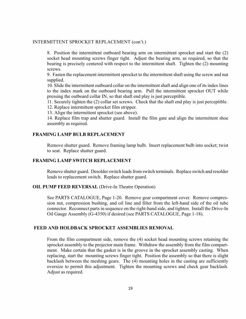
INTERMITTENT SPROCKET REPLACEMENT (con’t.)
8. Position the intermittent outboard bearing arm on intermittent sprocket and start the (2)socket head mounting screws finger tight. Adjust the bearing arm, as required, so that thebearing is precisely centered with respect to the intermittent shaft. Tighten the (2) mountingscrews.9. Fasten the replacement intermittent sprocket to the intermittent shaft using the screw and nutsupplied.10. Slide the intermittent outboard collar on the intermittent shaft and align one of its index linesto the index mark on the outboard bearing arm. Pull the intermittent sprocket OUT whilepressing the outboard collar IN, so that shaft end play is just perceptible.11. Securely tighten the (2) collar set screws. Check that the shaft end play is just perceptible.12. Replace intermittent sprocket film stripper.13. Align the intermittent sprocket (see above).14. Replace film trap and shutter guard. Install the film gate and align the intermittent shoeassembly as required.
FRAMING LAMP BULB REPLACEMENT
Remove shutter guard. Remove framing lamp bulb. Insert replacement bulb into socket; twistto seat. Replace shutter guard.
FRAMING LAMP SWITCH REPLACEMENT
Remove shutter guard. Desolder switch leads from switch terminals. Replace switch and resolderleads to replacement switch. Replace shutter guard.
OIL PUMP FEED REVERSAL (Drive-In Theatre Operation)
See PARTS CATALOGUE, Page 1-20. Remove gear compartment cover. Remove compres-sion nut, compression bushing, and oil line and filter from the left-hand side of the oil tubeconnector. Reconnect parts in sequence on the right-hand side, and tighten. Install the Drive-InOil Gauge Assembly (G-4350) if desired (see PARTS CATALOGUE, Page 1-18).
FEED AND HOLDBACK SPROCKET ASSEMBLIES REMOVAL
From the film compartment side, remove the (4) socket head mounting screws retaining thesprocket assembly to the projector main frame. Withdraw the assembly from the film compart-ment. Make certain that the gasket is in the groove in the sprocket assembly casting. Whenreplacing, start the mounting screws finger tight. Position the assembly so that there is slightbacklash between the meshing gears. The (4) mounting holes in the casting are sufficientlyoversize to permit this adjustment. Tighten the mounting screws and check gear backlash.Adjust as required.
19
FILM SPROCKET REPLACEMENT
1. Remove (1) of the (2) film stripper mounting screws. Loosen the other mounting screw androtate the stripper to clear the sprocket.2. Open the pad rollers.3. Remove the hex head sprocket fastening screw from the outboard end of the sprocket shaftand slide the sprocket from the shaft. Leave the spring washer and flat washer on the shaft.4. Slide the replacement sprocket (G-6611) onto the sprocket shaft, aligning the key in thesprocket with the keyway in the shaft. Secure with the sprocket fastening screw.5. Replace the film stripper.
FILM SPROCKET DRIVEN GEAR REPLACEMENT
1. Remove film sprocket assembly as a unit (see above).2. Remove gear fastening screw and slide gear from shaft.3. Slide replacement gear onto shaft. Insert the fastening screw, position the gear to allow slightend play, and securely tighten fastening screw.4. Replace sprocket assembly and adjust for backlash (see above).
PAD ROLLER ASSEMBLY REPLACEMENT
1. Remove film sprocket assembly as a unit (see above).2. Open pad rollers, compress actuating spring on the sprocket assembly so that the small holein one arm of the forked spring guide is accessible. Pass a pin or paper clip through this hole torelieve the spring tension.3. Remove pad roller assembly mounting screw and dismount pad roller arm.4. Replace worn components as required, reassemble, and remove the pin from the spring guide.Spacer washers, if used, are retained in their original positions. Make certain that the pad rollersare centered directly over the film sprocket.5. Position pad roller arm adjusting screw on the sprocket assembly casting so that, with (2)thicknesses of film between the sprocket and pad rollers, both pad rollers just rotate. Ensure thatthe adjusting screw locknut is then securely tightened.6. Reinstall sprocket assembly and adjust for backlash (see above).
SHUTTER REPLACEMENT
Remove the shutter guard. Disconnect the linkage to the changeover douser. Remove the (4)socket head mounting screws from the rear cover, and dismount the cover. Loosen the (2)shutter hub clamping screws and dismount shutter. Install replacement shutter and set shuttertime as detailed above. Replace the rear cover, douser linkage, and shutter guard.
20

SHUTTER TIMING
Place the shutter adjusting knob in its mid-position (see INTERMITTENT MOVEMENT RE-PLACEMENT, Step 2). Remove the shutter guard. Turn the projector mechanism by hand sothat the index mark on the intermittent outboard bearing arm (Item 1) is centered between twoof the collar index lines (Item 3). Loosen the two socket head shutter hub clamping screws(Item 4). Rotate the shutter (Item 1) to the fully closed position (one blade completely coveringthe film aperture, as shown). Tighten the two clamping screws. Replace the shutter guard.Check projected picture; fine adjustment of the shutter adjustment knob may be required toeliminate travel ghost (see START-UP PROCEDURES).
21