Embed Size (px)
Citation preview
7/27/2019 31801183 Idler Roller
http://slidepdf.com/reader/full/31801183-idler-roller 1/308
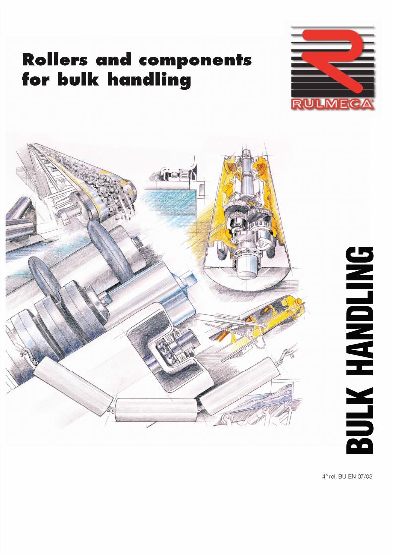
Rollers and componentsfor bulk handling
4° rel. BU EN 07/

7/27/2019 31801183 Idler Roller
http://slidepdf.com/reader/full/31801183-idler-roller 2/308
Translation, reproduction and adaption rights,total and/or partial, by any means (microfilms
and photostatic copies included) are reservedfor all Countries.
7/27/2019 31801183 Idler Roller
http://slidepdf.com/reader/full/31801183-idler-roller 3/308
1
Rollers and componentsfor bulk handling
®
7/27/2019 31801183 Idler Roller
http://slidepdf.com/reader/full/31801183-idler-roller 4/308
2
®
TABLE OF CONTENTS
1 Technical information page 9
1.1 Introduction ................................................................ 11
1.2 Technical symbols ..................................................... 12
1.3 Technical characteristics of belt conveyors ............. 14
1.4 Component elements of a belt conveyor .................. 16
1.5 Project criteria ........................................................... 181.5.1 Conveyed Material ....................................................... 181.5.2 Belt speed ................................................................... 231.5.3 Belt width ................................................................... 241.5.4 Type of troughing set, pitch and transition distance ...... 321.5.5 Tangential force, absorbed power, passive .................. 36
resistance, belt weight, tensions and checks
1.5.6 Belt conveyor drive types and drum dimensions .......... 44
1.6 Rollers, function and critical data ............................ 481.6.1 Choice of roller diameter in relation to speed ................ 491.6.2 Choice of type in relation to load ................................. 50
1.7 Loading of belt and impact rollers .............................. 531.7.1 Calculation of associated forces on impact rollers ........ 54
1.8 Accessories ............................................................... 581.8.1 Belt cleaners ............................................................... 581.8.2 Belt inversion ............................................................... 591.8.3 Belt conveyor covers ................................................... 59
1.9 Project examples ...................................................... 60
2 Rollers page 67
2.1 Various industry uses ................................................ 69
2.2 Rollers, technical design and data ........................... 70
2.3 Selection method ...................................................... 742.3.1 Choice of diameter in relation to speed ........................ 752.3.2 Choice of type in relation to load .................................. 76
2.4 Ordering codes .......................................................... 80
2.5 Programme ................................................................ 892.5.1 Rollers series PSV ........................................................ 91
Rollers series PSV non standard ................................... 1202.5.2 Rollers series PL - PLF ................................................. 1212.5.3 Rollers series MPS - M ................................................. 133
2.5.4 Rollers series MPR ...................................................... 1492.5.5 Rollers series RTL ........................................................ 1552.5.6 Guide rollers ................................................................ 161
2.6 Rollers with rubber rings ........................................... 1642.6.1 Impact rollers ............................................................... 1662.6.2 Return rollers with spaced rubber rings ......................... 1762.6.3 Return rollers with helical rubber rings .......................... 188
for self cleaning2.6.4 Return rollers with helical steel cage ............................. 192
for self cleaning
7/27/2019 31801183 Idler Roller
http://slidepdf.com/reader/full/31801183-idler-roller 5/308
7/27/2019 31801183 Idler Roller
http://slidepdf.com/reader/full/31801183-idler-roller 6/308
4
®
7/27/2019 31801183 Idler Roller
http://slidepdf.com/reader/full/31801183-idler-roller 7/308
5
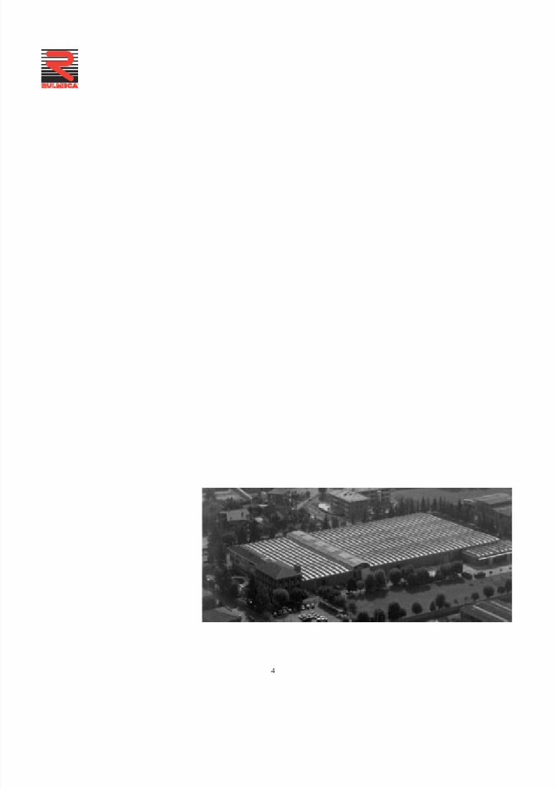
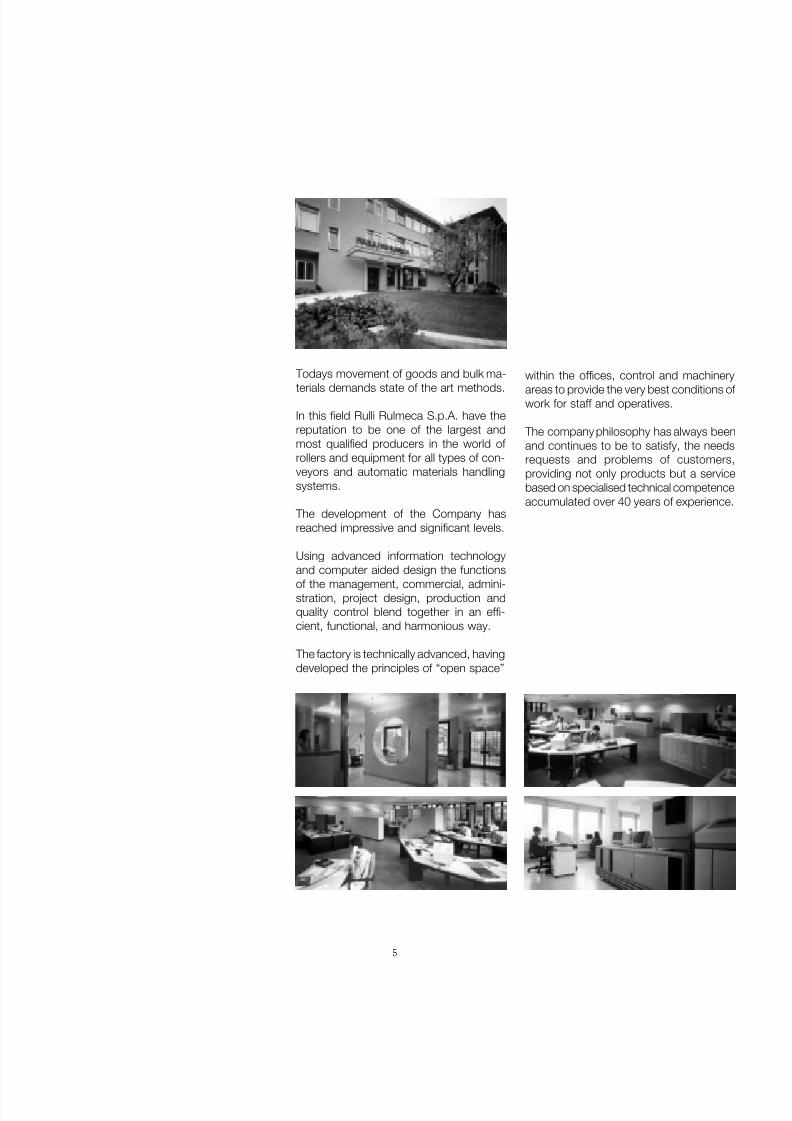
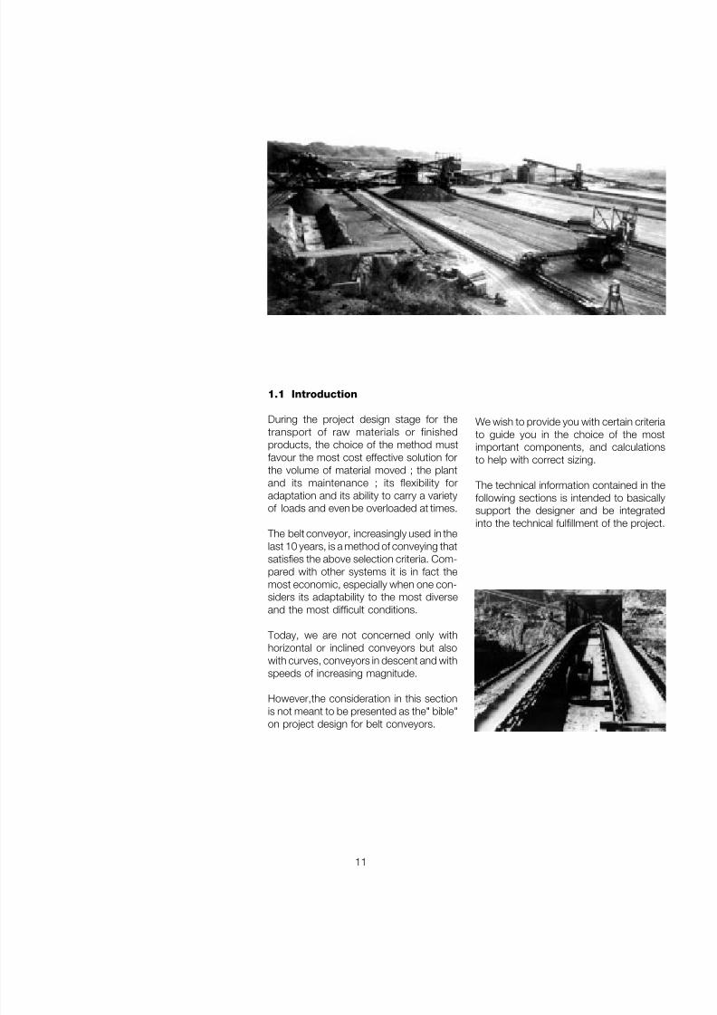
Todays movement of goods and bulk ma-terials demands state of the art methods.
In this field Rulli Rulmeca S.p.A. have thereputation to be one of the largest andmost qualified producers in the world of rollers and equipment for all types of con-veyors and automatic materials handlingsystems.
The development of the Company hasreached impressive and significant levels.
Using advanced information technologyand computer aided design the functionsof the management, commercial, admini-stration, project design, production andquality control blend together in an effi-cient, functional, and harmonious way.
The factory is technically advanced, havingdeveloped the principles of “open space”
within the offices, control and machineryareas to provide the very best conditions of work for staff and operatives.
The company philosophy has always beenand continues to be to satisfy, the needsrequests and problems of customers,providing not only products but a servicebased on specialised technical competenceaccumulated over 40 years of experience.
7/27/2019 31801183 Idler Roller
http://slidepdf.com/reader/full/31801183-idler-roller 8/308
6
®
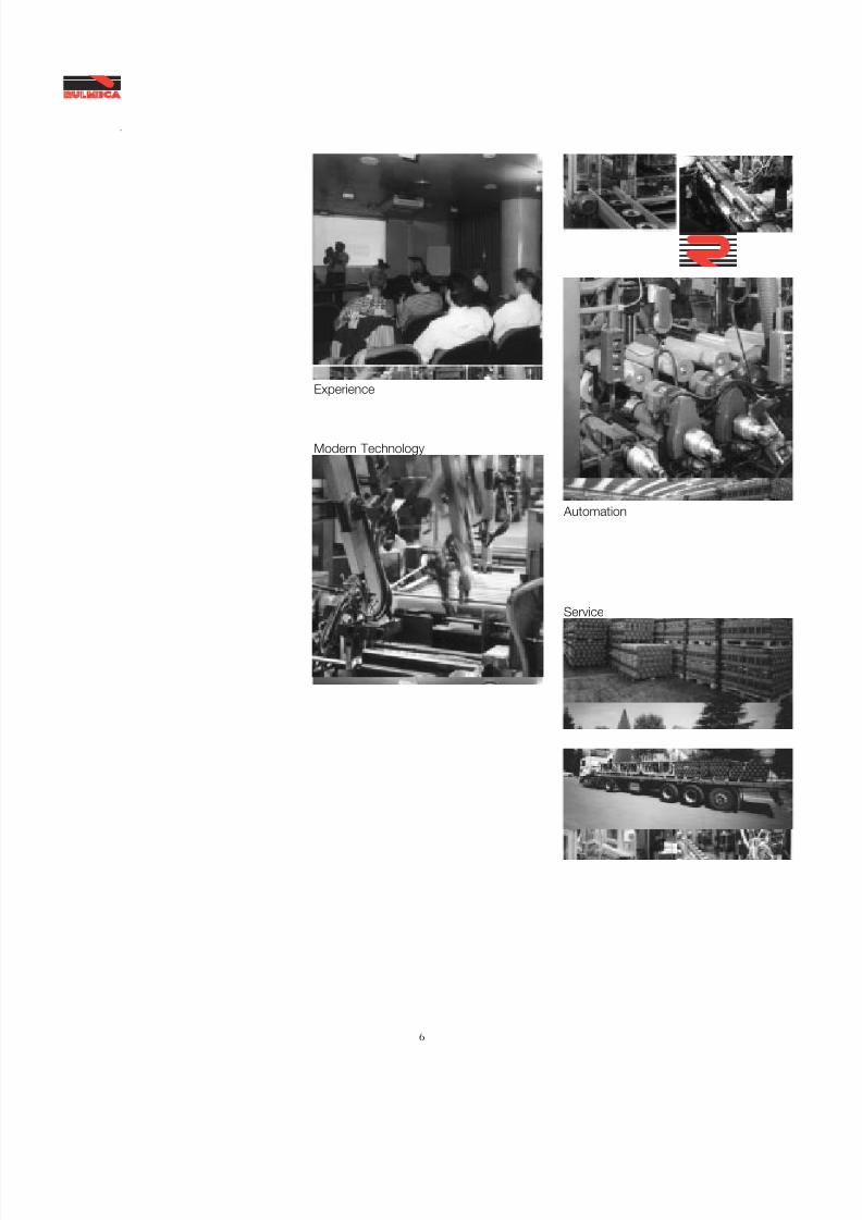
Experience
Service
Modern Technology
Automation
7/27/2019 31801183 Idler Roller
http://slidepdf.com/reader/full/31801183-idler-roller 9/308
7
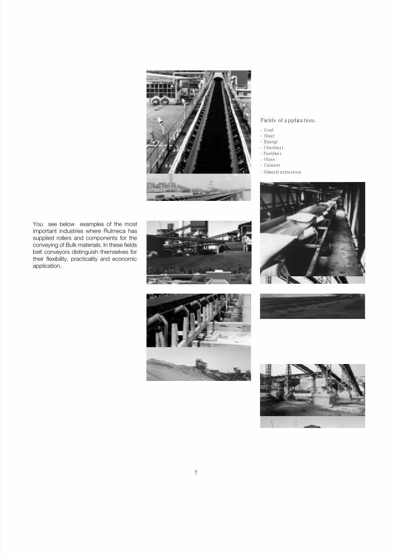
- Coal- Steel- Energy- Chemica l- Fertilise r- Glass- Cement
- Mineral extra ction
You see below examples of the mostimportant industries where Rulmeca hassupplied rollers and components for theconveying of Bulk materials. In these fieldsbelt conveyors distinguish themselves fortheir flexibility, practicality and economicapplication.
Fields of a pplica tion:

7/27/2019 31801183 Idler Roller
http://slidepdf.com/reader/full/31801183-idler-roller 10/308
8
Technical
Informationproject and design criteriafor belt conveyors
1
®

7/27/2019 31801183 Idler Roller
http://slidepdf.com/reader/full/31801183-idler-roller 11/308
9
1 TechnicalInformationproject and design criteriafor belt conveyors
7/27/2019 31801183 Idler Roller
http://slidepdf.com/reader/full/31801183-idler-roller 12/308
10
Technical
Informationproject and design criteriafor belt conveyors
1
®
Summary 1 Technical information page 9
1.1 Introduction ................................................................ 11
1.2 Technical symbols ..................................................... 12
1.3 Technical characteristics of belt conveyors ............. 14
1.4 Component elements of a belt conveyor .................. 16
1.5 Project criteria ........................................................... 181.5.1 Conveyed Material ....................................................... 181.5.2 Belt speed ................................................................... 231.5.3 Belt width ................................................................... 241.5.4 Type of troughing set, pitch and transition distance ...... 321.5.5 Tangential force, absorbed power, passive .................. 36
resistance, belt weight, tensions and checks1.5.6 Belt conveyor drive types and drum dimensions .......... 44
1.6 Rollers, function and crit ical data ............................ 481.6.1 Choice of roller diameter in relation to speed ................ 491.6.2 Choice of type in relation to load ................................. 50
1.7 Loading of belt and impact rollers .............................. 531.7.1 Calculation of associated forces on impact rollers ........ 54
1.8 Accessories ............................................................... 581.8.1 Belt cleaners ............................................................... 581.8.2 Belt inversion ............................................................... 591.8.3 Belt conveyor covers ................................................... 59
1.9 Project examples ...................................................... 60
7/27/2019 31801183 Idler Roller
http://slidepdf.com/reader/full/31801183-idler-roller 13/308
11
1.1 Introduction
During the project design stage for thetransport of raw materials or finishedproducts, the choice of the method mustfavour the most cost effective solution forthe volume of material moved ; the plantand its maintenance ; its flexibility foradaptation and its ability to carry a varietyof loads and even be overloaded at times.
The belt conveyor, increasingly used in thelast 10 years, is a method of conveying thatsatisfies the above selection criteria. Com-pared with other systems it is in fact themost economic, especially when one con-siders its adaptability to the most diverseand the most difficult conditions.
Today, we are not concerned only withhorizontal or inclined conveyors but alsowith curves, conveyors in descent and withspeeds of increasing magnitude.
However,the consideration in this sectionis not meant to be presented as the" bible"on project design for belt conveyors.
We wish to provide you with certain criteriato guide you in the choice of the mostimportant components, and calculationsto help with correct sizing.
The technical information contained in thefollowing sections is intended to basicallysupport the designer and be integrated
into the technical fulfillment of the project.
7/27/2019 31801183 Idler Roller
http://slidepdf.com/reader/full/31801183-idler-roller 14/308
12
Technical
Informationproject and design criteriafor belt conveyors
1
®
1.2 Technical Symbols
a pitch of troughing sets m
A length of roller spindle mma g distance between the pulley flange and support ma i pitch of impact sets ma o pitch of carrying sets ma t pitch of transition sets ma u pitch of return sets mB length of roller shell mmC distance between roller supports mmCa static load on the carrying set daNca load on central roller of the carrying set daNCa 1 dynamic load on the carrying set daNcd dynamic load on the bearing daNCf constant of elasticity of the frame/impact roller Kg/mch flats of roller shaft mmCo static load on bearing daNCp resulting load of associated forces on motorised drum shaft daNCp r resulting load of associated forces on idler drum shaft daNCq coefficient of fixed resistance __
Cr static load on the return set daNc r load on the roller of return set daNCr 1 dynamic load on the return set daNCt coefficient of passive resistance given by temperature __
Cw wrap factor __
d diameter of spindle/shaft mmD diameter of roller/pulley mmE modules of elasticity of steel daN/mm 2
e logarithmic natural base 2,718f coefficient of internal friction of material and of rotating parts __
f a coefficient of friction between the belt and drum given an angleof wrap __
f r deflection of belt between two consecutive troughing sets mft deflection of a symmetrical shaft mmFa tangential force to move the belt in the direction of movement daNFd factor of impact __
Fm environmental factor __
Fp contribution factor __
Fp r contribution factor on the central roller of a troughing set __
Fr tangential force to move the belt in the return direction daNFs service factor __
Fu total tangential force daNFv speed factor __
G distance between support brackets mmGm weight of lump of material KgH height change of belt mHc corrected height of fall mHf height of fall of material belt-screen mHt height change between motorised drum and counterweight mHv height of fall of material screen - receiving belt mIC distance from centre of motorised drum to the centre of
the counterweight connection mIM load volume m 3 /hI V belt load (material flow) t/h
7/27/2019 31801183 Idler Roller
http://slidepdf.com/reader/full/31801183-idler-roller 15/308
13
I VM load volume corrected to 1 m/s in relation to the inclination
and irregularity of the feed m3
/hI VT load volume theoretic to 1 m/s m 3 /hJ moment of inertia of section of material mm 4
K inclination factor __
K 1 correction factor __
σamm admissible stress daN/mmL load centres mLb dimensions of material lump mLt transition distance mMf bending moment daNmMif ideal bending moment daNmMt torsion moment daNmN belt width mmn revolutions per minute rpm
P absorbed power kWp d dynamic falling force Kgp i impact force of falling material Kgp ic force impact on central roller KgPpri weight of lower rotating parts KgPprs weight of upper rotating parts Kgq b weight of belt per linear metre Kg/mq bn weight of belt density Kg/m 2
q G weight of material per linear metre Kg/mq RO weight of the upper rotating parts referred to the troughing set pitch Kg/mq RU weight of the lower rotating parts referred to the troughing set pitch Kg/mqs specific weight t/m 3
q T weight of drum daNRL length of motorised drum face mmS section of belt material m 2
T 0 minimum tension at end of load zone daN T 1 tension on input side daN T 2 tension on output side daN T 3 tension on idler drum daN Tg tension on belt at the point of counterweight connection daN T max tension at point of highest belt stress daN Tu max unitary maximum tension of belt daN/mm Tx tension of the belt at a considered point daN Ty tension of the belt at a considered point daNv belt speed m/s
V maximum rise of edge of belt mmW module of resistance mm 3
α angle of wrap of belt on pulley degreeeα t inclination of rotating symmetrical shaft radβ angle of overload degreeeγ angle of screen inclination degreeeδ inclination of conveyor degreeeλ inclination of side roller of troughing set degreeeλ1 inclination of intermediate side roller degreeeλ2 inclination of external side roller degreeeη efficiency __
y angle deflection of bearing degreee The symbol for kilogram (kg) is intendedas a unit of force.
7/27/2019 31801183 Idler Roller
http://slidepdf.com/reader/full/31801183-idler-roller 16/308
14
Technical
Informationproject and design criteriafor belt conveyors
1
®
Based on the load large belt conveyors areable to show cost add savings of up
to 40-60 % with respect to truck or lorrytransport.
The electrical and mechanical componentsof the conveyor such as rollers, drumsbearings, motors etc.... are producedaccording to the highest standards. Thequality level reached by majormanufacturers guarantees function andlong life.
The principal components of the conveyor,rollers and belt, need very little maintenanceproviding the design and the installation
has been correctly performed. Theelastomer belt needs only occasional orsuperficial repair and as the rollers aresealed for life they need no lubrication. Thehigh quality and advanced technology of Rulmeca may reduce even further, orsubstitute, the need for ordinarymaintenance.Drum lagging has a life of at least twoyears.
The utilisation of adequate accessories toclean the belt at the feed and dischargepoints yields corresponding improvementsto increase the life of the installation withminor maintenance.
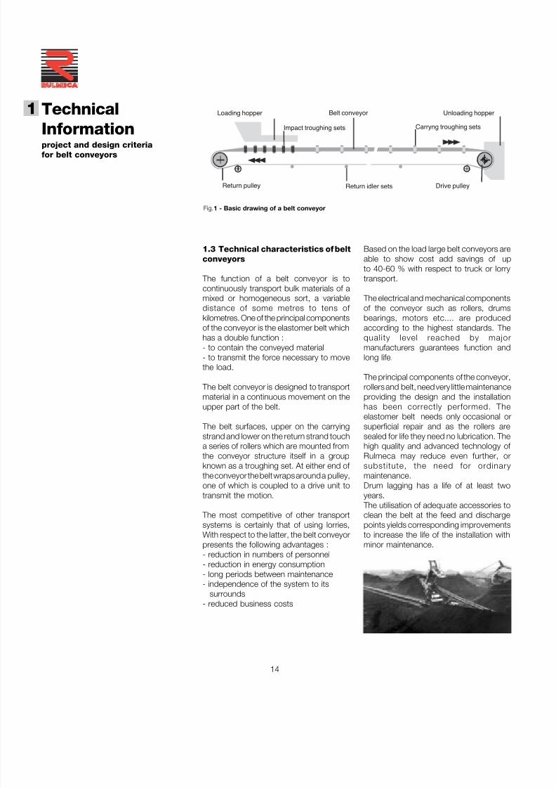
1.3 Technical characteristics of beltconveyors
The function of a belt conveyor is tocontinuously transport bulk materials of amixed or homogeneous sort, a variabledistance of some metres to tens of kilometres. One of the principal componentsof the conveyor is the elastomer belt whichhas a double function :- to contain the conveyed material- to transmit the force necessary to movethe load.
The belt conveyor is designed to transportmaterial in a continuous movement on the
upper part of the belt.
The belt surfaces, upper on the carryingstrand and lower on the return strand toucha series of rollers which are mounted fromthe conveyor structure itself in a groupknown as a troughing set. At either end of the conveyor the belt wraps around a pulley,one of which is coupled to a drive unit totransmit the motion.
The most competitive of other transportsystems is certainly that of using lorries,With respect to the latter, the belt conveyorpresents the following advantages :- reduction in numbers of personnel- reduction in energy consumption- long periods between maintenance- independence of the system to its
surrounds- reduced business costs
Loading hopper
Return idler sets
Unloading hopper
Drive pulleyReturn pulley
Carryng troughing setsImpact troughing sets
Belt conveyor
Fig.1 - Basic drawing of a belt conveyor
7/27/2019 31801183 Idler Roller
http://slidepdf.com/reader/full/31801183-idler-roller 17/308
15
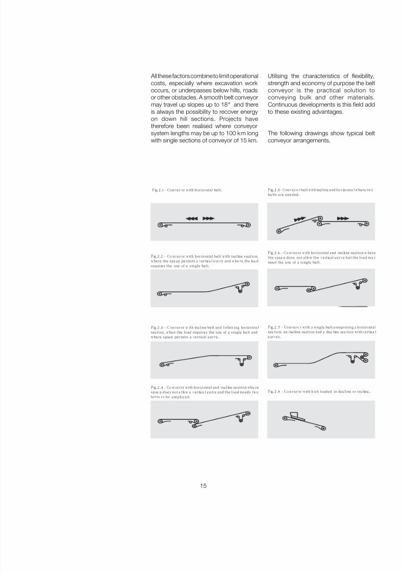
All these factors combine to limit operationalcosts, especially where excavation work occurs, or underpasses below hills, roads
or other obstacles. A smooth belt conveyormay travel up slopes up to 18 ° and thereis always the possibility to recover energyon down hill sections. Projects havetherefore been realised where conveyorsystem lengths may be up to 100 km longwith single sections of conveyor of 15 km.
Utilising the characteristics of flexibility,strength and economy of purpose the beltconveyor is the practical solution to
conveying bulk and other materials.Continuous developments is this field addto these existing advantages.
The following drawings show typical beltconveyor arrangements.
Fig.2.1- Convey or with horizontal belt. Fig.2.5- Conveyo r belt with incline and ho rizonta l where two
belts are needed.
Fig.2.2 - Co nveyor with horizontal belt with incline s ection,where the spa ce permits a vertica l curve and whe re the loa drequires the use of a single belt.
Fig.2.8 - Co nveyor with b elt loaded in decline or incline.
Fig.2.4 - Co nveyor with horizontal and incline se ction whe re
spac e does not a l low a vertica l curve and the load needs twobelts to be employed.
Fig.2.3 - C onveyor w ith incline belt and following horizonta lsection, when the load requires the use of a single belt andwhere space permits a vertical curve.
Fig.2.6 - Co nveyor with horizontal and incline section w herethe spac e does not al low the vert ical curve but the load ma yneed the use of a single belt.
Fig.2.7 - Conveyo r with a single belt comprising a horizontalsec tion, an incline section and a dec line sec tion with vertica lcurves.
7/27/2019 31801183 Idler Roller
http://slidepdf.com/reader/full/31801183-idler-roller 18/308
16
Technical
Informationproject and design criteriafor belt conveyors
1
®
Drive pulley The shell face of the conventional drivepulley or the motorised drum may be left asnormal finish or clad in rubber of a thicknesscalculated knowing the power to betransmitted.
Th e cl ad din g ma y be gr oo ve d asherringbone design ; or horizontal groovesto the direction of travel ; or diamondgrooves ; all designed to increase thecoefficient of friction and to facilitate therelease of water from the drum surface.
The dr um di amet er is di mens ionedaccording to the class and type of belt andto the designed pressures on its surface.
Return pulleys The shell face does not necessarily need tobe clad except in certain cases, and thediameter is normally less than that designedfor the drive pulley.
Deflection or snub pulleys These are used to increase the angle of wrap of the belt and overall for all thenecessary changes in belt direction in theareas of counterweight tensioner, mobileunloader etc..
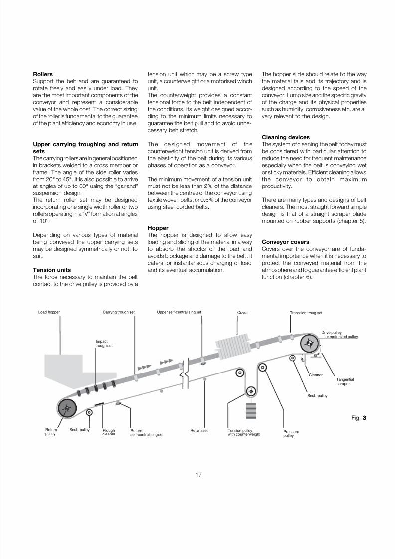
1.4 Components and their sizing
Fig. 3 illustrates the basic components of atypical belt conveyor. In practice, accordingto the variety of uses, it is possible to havemany other diverse combinations of loadand unload areas, elevations, and otheraccessories.
Drive headMay be of traditional design or withmotorised drum unit.- TraditionalComprises a drive group consisting of : adrive drum of a diameter appropriatelysized to the load on the belt, and an idlerdrum at the opposing end. The power issupplied by a direct coupled motor gearboxor by a direct or parallel shaft drive drivingthe drive drum through a suitably sizedcouple.
- Motorised DrumIn this arrangement the motor, gearboxand bearings form a complete designedunit inside and protected by the drum shellwhich directly powers the belt. This
eliminates all the external complication of external drive, couples etc. as describedabove in the traditional design. Todaymotorised drums are produced in diametersup to 800mm with power in the order of 130 KW and with a drive efficiency whichmay reach 97 %.
7/27/2019 31801183 Idler Roller
http://slidepdf.com/reader/full/31801183-idler-roller 19/308
17
tension unit which may be a screw typeunit, a counterweight or a motorised winchunit.
The counterweight provides a constanttensional force to the belt independent of the conditions. Its weight designed accor-ding to the minimum limits necessary toguarantee the belt pull and to avoid unne-cessary belt stretch.
Th e de si gn ed mo ve me nt of th ecounterweight tension unit is derived fromthe elasticity of the belt during its variousphases of operation as a conveyor.
The minimum movement of a tension unitmust not be less than 2% of the distancebetween the centres of the conveyor usingtextile woven belts, or 0.5% of the conveyorusing steel corded belts.
Hopper The hopper is designed to allow easyloading and sliding of the material in a wayto absorb the shocks of the load andavoids blockage and damage to the belt . Itcaters for instantaneous charging of loadand its eventual accumulation.
The hopper slide should relate to the waythe material falls and its trajectory and isdesigned according to the speed of the
conveyor. Lump size and the specific gravityof the charge and its physical propertiessuch as humidity, corrosiveness etc. are allvery relevant to the design.
Cleaning devices The system of cleaning the belt today mustbe considered with particular attention toreduce the need for frequent maintenanceespecially when the belt is conveying wetor sticky materials. Efficient cleaning allowsthe conveyor to obtain maximumproductivity.
There are many types and designs of beltcleaners. The most straight forward simpledesign is that of a straight scraper blademounted on rubber supports (chapter 5).
Conveyor coversCovers over the conveyor are of funda-mental importance when it is necessary toprotect the conveyed material from theatmosphere and to guarantee efficient plantfunction (chapter 6).
Load hopper
Returnself-centralising set
Snub pulleycleanerPlough
Carryng trough set
Drive pulleyor motorized pulley
Cleaner
Upper self-centralising set Transition troug setCover
Returnpulley
Impacttrough set
Pressurepulley
scraper
Tangential
Return set Tension pulleywith counterweight
Snub pulley
Fig.
RollersSupport the belt and are guaranteed torotate freely and easily under load. They
are the most important components of theconveyor and represent a considerablevalue of the whole cost. The correct sizingof the roller is fundamental to the guaranteeof the plant efficiency and economy in use.
Upper carrying troughing and returnsets
The carrying rollers are in general positionedin brackets welded to a cross member orframe. The angle of the side roller variesfrom 20 ° to 45 °. It is also possible to arriveat angles of up to 60 ° using the “garland”suspension design.
The return roller set may be designedincorporating one single width roller or tworollers operating in a “V” formation at anglesof 10 ° .
Depending on various types of materialbeing conveyed the upper carrying setsmay be designed symmetrically or not, tosuit.
Tension units The force necessary to maintain the beltcontact to the drive pulley is provided by a
7/27/2019 31801183 Idler Roller
http://slidepdf.com/reader/full/31801183-idler-roller 20/308

7/27/2019 31801183 Idler Roller
http://slidepdf.com/reader/full/31801183-idler-roller 21/308
19
The conveyed material set tles into aconfiguration as shown in sectional diagramFig. 6.
The area of the section “S” may becalculated geometrically adding the area of a circle A 1 to that of the trapezoid A 2 .
The value of the conveyed volume 1VT maybe easily calculated using the formula :
I VT
S = _________ [ m 2 ]3600
where :
I VT = conveyed volume at a conveyorspeed of 1 m/s ( see Tab .5 a-b-c-d )
General everyday
material as for
example
bituminous coal
and the majority of
minerals.
Irregular viscous
fibrous material
which tends to get
worse in handling,
as for example
wood shavings,
sugar cane by
product, foundry
sand, etc.
Partly rounded
particles, dry and
smooth.
Average weight as
for example cereal,
grain and beans.
Irregular material,
granular particles of
average weight as
for example
anthracite coal,
clay etc.
Here may be
included materials
with a variety of
characteristics as
indicated in the
following Tab .2.
Fluency Profile
very high high medium low on a flat belt
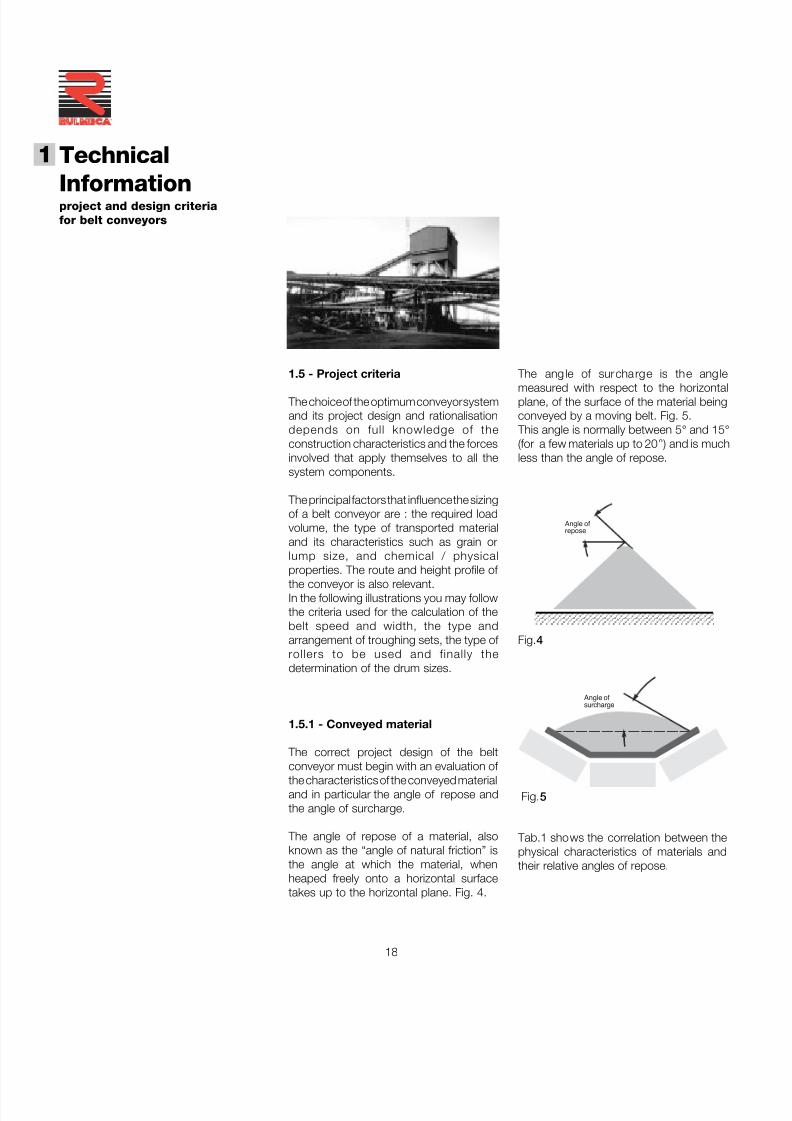
An gle of surcharge βββββ
5° 10 ° 20 ° 25 ° 30 ° ß
An gle of repose
0-19 ° 20-29 ° 30-34 ° 35-39 ° 40 ° and more Others
Characteristics of materials
Fig.6
SA1
A2
S = A 1 + A 2
Uniform dimensions,
round particles, very
small size.
Very humid or very
dry such as dry
sand, silica, cement
and wet limestone
dust etc.
Tab. 1 - Angles of surcharge, repose, and material fluency
7/27/2019 31801183 Idler Roller
http://slidepdf.com/reader/full/31801183-idler-roller 22/308
20
Technical
Informationproject and design criteriafor belt conveyors
1
®
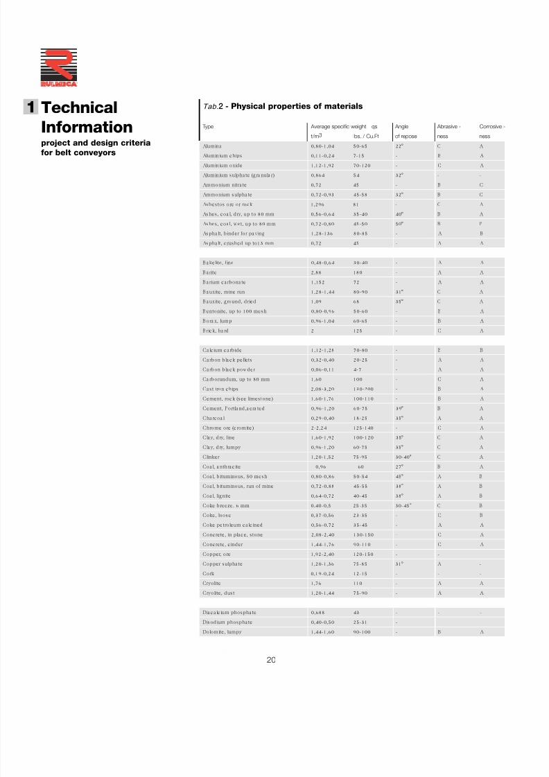
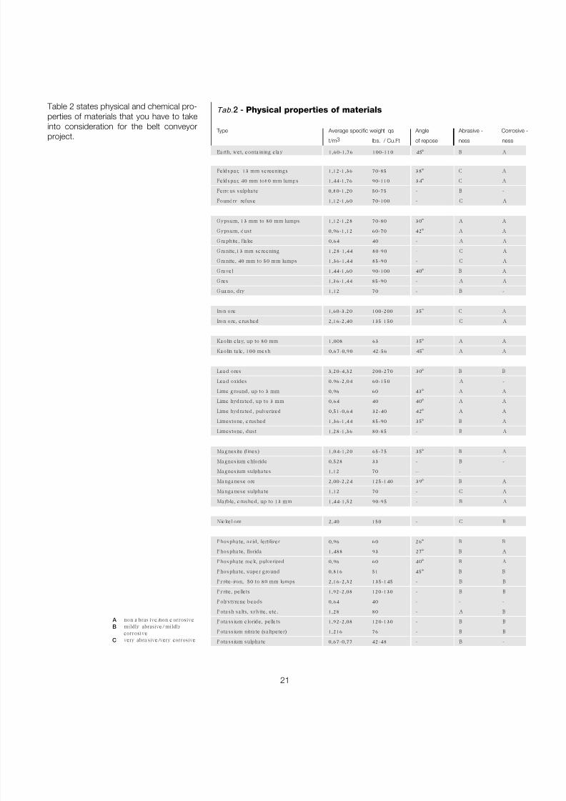
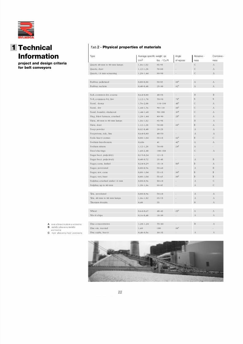
Tab. 2 - Physical properties of materials
Type Average specific weight qs Angle Abrasive - Corrosive -
t/m 3 lbs. / Cu.Ft of repose ness ness
Alumina 0,80-1,04 50-65 22 ° C A
Aluminium chips 0,11-0,24 7-15 - B A
Aluminium oxide 1,12-1,92 70-120 - C A
Aluminium sulpha te (g ra nula r) 0,864 54 32 ° - -
Ammonium nitra te 0,72 45 - B C
Ammonium sulpha te 0,72-0,93 45-58 32 ° B C
Asbes tos ore or rock 1,296 81 - C A
Ashes, coa l, d ry, up to 80 mm 0,56-0,64 35-40 40 ° B A
Ashes, coa l, wet, up to 80 mm 0,72-0,80 45-50 50 ° B P
Aspha lt, b inder for pa ving 1,28-136 80-85 - A B
Aspha lt, c rushed up to13 mm 0,72 45 - A A
B a kelite, fine 0,48-0,64 30-40 - A A
B a rite 2,88 180 - A A
B a rium c a rbona te 1,152 72 - A A
B a uxite, mine run 1,28-1,44 80-90 31 ° C A
B a uxite, g round , d ried 1,09 68 35 ° C A
B entonite, up to 100 mesh 0,80-0,96 50-60 - B A
B ora x, lump 0,96-1,04 60-65 - B A
B rick, ha rd 2 125 - C A
Ca lc ium c a rb ide 1,12-1,28 70-80 - B B
Ca rbon b la ck pellets 0,32-0,40 20-25 - A A
Ca rbon b la ck pow der 0,06-0,11 4-7 - A A
Ca rborundum, up to 80 mm 1,60 100 - C A
Ca s t iron chips 2,08-3,20 130-200 - B A
Cement, roc k (see limes tone) 1,60-1,76 100-110 - B ACement, P ortla nd ,a era ted 0,96-1,20 60-75 39 ° B A
Cha rcoa l 0,29-0,40 18-25 35 ° A A
Chrome ore (c romite) 2-2,24 125-140 - C A
Cla y, d ry, fine 1,60-1,92 100-120 35 ° C A
Cla y, d ry, lumpy 0,96-1,20 60-75 35 ° C A
Clinker 1,20-1,52 75-95 30-40 ° C A
Coa l, a nthra c ite 0,96 60 27 ° B A
Coa l, b ituminous, 50 mesh 0,80-0,86 50-54 45 ° A B
Coa l, b ituminous, run of mine 0,72-0,88 45-55 38 ° A B
Coa l, lignite 0,64-0,72 40-45 38 ° A B
Coke b reeze, 6 mm 0,40-0,5 25-35 30-45 ° C B
Coke, loose 0,37-0,56 23-35 - C B
Coke petro leum ca lc ined 0,56-0,72 35-45 - A A
Concrete, in pla c e, s tone 2,08-2,40 130-150 - C AConcrete, c inder 1,44-1,76 90-110 - C A
Copper, ore 1,92-2,40 120-150 - - -
Copper sulpha te 1,20-1,36 75-85 31 ° A -
Cork 0,19-0,24 12-15 - - -
Cryolite 1,76 110 - A A
Cryo lite, dus t 1,20-1,44 75-90 - A A
Dia c a lc ium phospha te 0,688 43 - - -
Disod ium phospha te 0,40-0,50 25-31 -
Dolomite, lumpy 1,44-1,60 90-100 - B A
7/27/2019 31801183 Idler Roller
http://slidepdf.com/reader/full/31801183-idler-roller 23/308
21
non a bras ive/non c orrosivemildly abrasive/mildlycorrosivevery abra sive/very corrosive
A B
C
Tab. 2 - Physical properties of materials
Type Average specific weight qs Angle Abrasive - Corrosive -
t/m 3 lbs. / Cu.Ft of repose ness ness
Ea rth, wet, conta ining c la y 1,60-1,76 100-110 45 ° B A
Feldspa r, 13 mm sc reenings 1,12-1,36 70-85 38 ° C A
Feldspa r, 40 mm to80 mm lumps 1,44-1,76 90-110 34 ° C A
Ferrous sulpha te 0,80-1,20 50-75 - B -
Foundry refuse 1,12-1,60 70-100 - C A
G ypsum, 13 mm to 80 mm lumps 1,12-1,28 70-80 30 ° A A
G ypsum, dus t 0,96-1,12 60-70 42 ° A A
G ra phite, fla ke 0,64 40 - A A
G ra nite,13 mm sc reening 1,28-1,44 80-90 - C A
G ra nite, 40 mm to 50 mm lumps 1,36-1,44 85-90 - C A
G ra vel 1,44-1,60 90-100 40 ° B A
G res 1,36-1,44 85-90 - A A
G ua no, d ry 1,12 70 - B -
Iron ore 1,60-3,20 100-200 35 ° C A
Iron ore, c rushed 2,16-2,40 135-150 - C A
Ka olin c la y, up to 80 mm 1,008 63 35 ° A A
Ka olin ta lc , 100 mesh 0,67-0,90 42-56 45 ° A A
Lea d ores 3,20-4,32 200-270 30 ° B B
Lea d oxides 0.96-2,04 60-150 - A -
Lime g round , up to 3 mm 0,96 60 43 ° A A
Lime hydra ted , up to 3 mm 0,64 40 40 ° A A
Lime hydra ted , pulverized 0,51-0,64 32-40 42 ° A ALimes tone, c rushed 1,36-1,44 85-90 35 ° B A
Limes tone, dus t 1,28-1,36 80-85 - B A
Ma g nes ite (fines) 1,04-1,20 65-75 35 ° B A
Ma gnes ium chlo ride 0,528 33 - B -
Ma gnes ium sulpha tes 1,12 70 -- -
Ma nga nese ore 2,00-2,24 125-140 39 ° B A
Ma nga nese sulpha te 1,12 70 - C A
Ma rb le, c rushed , up to 13 mm 1,44-1,52 90-95 - B A
Nic kel ore 2,40 150 - C B
P hospha te, a c id , fertilizer 0,96 60 26 ° B B
P hospha te, florida 1,488 93 27 ° B A
P hospha te roc k, pulverized 0,96 60 40 ° B A
P hospha te, super g round 0,816 51 45 ° B B
P yrite-iron, 50 to 80 mm lumps 2,16-2,32 135-145 - B B
P yrite , pellets 1,92-2,08 120-130 - B B
P olystyrene bea ds 0,64 40 - - -
P ota sh sa lts , sylvite , etc . 1,28 80 - A B
P ota ss ium c loride, pellets 1,92-2,08 120-130 - B B
P ota ss ium nitra te (sa ltpeter) 1,216 76 - B B
P ota ssium sulpha te 0,67-0,77 42-48 - B -
Table 2 states physical and chemical pro-perties of materials that you have to takeinto consideration for the belt conveyor
project.
7/27/2019 31801183 Idler Roller
http://slidepdf.com/reader/full/31801183-idler-roller 24/308
22
Technical
Informationproject and design criteriafor belt conveyors
1
®
A non a bras ive/non c orrosiveB mildly a bra sive/mildly
corrosiveC very abra sive/very corrosive
Tab. 2 - Physical properties of materials
Type Average specific weight qs Angle Abrasive - Corrosive -
t/m 3 lbs. / Cu.Ft of repose ness ness
Qua rtz 40 mm to 80 mm lumps 1,36-1,52 85-95 - C A
Qua rtz, dus t 1,12-1,28 70-80 - C A
Qua rtz, 13 mm sc reening 1,28-1,44 80-90 - C A
Rubber, pelletized 0,80-0,88 50-55 35 ° A A
Rubber, rec la im 0,40-0,48 25-30 32 ° A A
S a lt, c ommon d ry, c oa rse 0,64-0,88 40-55 - B B
S a lt, c ommon d ry, fine 1,12-1,28 70-80 25 ° B B
S a nd , da mp 1,76-2,08 110-130 45 ° C A
S a nd , d ry 1,44-1,76 90-110 35 ° C A
S a nd , foundry, sha keout 1,44-1,60 90-100 39 ° C A
S la g , b la st furna ce, c rushed 1,28-1,44 80-90 25 ° C A
S la te, 40 mm to 80 mm lumps 1,36-1,52 85-95 - B A
S la te, dus t 1,12-1,28 70-80 35 ° B A
S oa p powder 0,32-0,40 20-25 - A A
S oa ps tone, ta lc , fine 0,64-0,80 40-50 - A A
S oda hea vy a smes 0,88-1,04 55-65 32 ° B C
S odium b ic a rbona te 0,656 41 42 ° A A
S odium nitra te 1,12-1,28 70-80 24 ° A -
S teel sha vings 1,60-2,40 100-150 - C A
S uga r beet, pulp (d ry) 0,19-0,24 12-15 - - -
S uga r beet, pulp (w et) 0,40-0,72 25-45 - A B
S uga r, ca ne, knifed 0,24-0,29 15-18 50 ° B A
S uga r, powdered 0,80-0,96 50-60 - A B
S uga r, ra w, c a ne 0,88-1,04 55-65 30 ° B B
S uga r, wet, beet 0,88-1,04 55-65 30 ° B BS ulphur, c rushed under 13 mm 0,80-0,96 50-60 - A C
S ulphur, up to 80 mm 1,28-1,36 80-85 - A C
Ta lc , powdered 0,80-0,96 50-60 - A A
Ta lc , 40 mm to 80 mm lumps 1,36-1,52 85-95 - A A
Tita nium d ioxide 0,40 25 - B A
Whea t 0,64-0,67 40-42 25 ° A A
Wood c hips 0,16-0,48 10-30 - A A
Zinc c onc entra tes 1,20-1,28 75-80 - B A
Zinc ore, roa s ted 1,60 100 38 ° - -
Zinc oxide, hea vy 0,48-0,56 30-35 - A A
7/27/2019 31801183 Idler Roller
http://slidepdf.com/reader/full/31801183-idler-roller 25/308
23
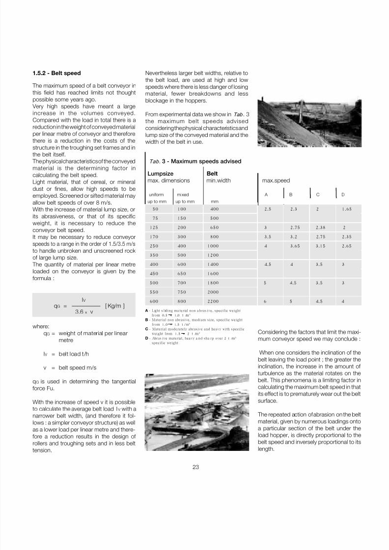
1.5.2 - Belt speed
The maximum speed of a belt conveyor in
this field has reached limits not thoughtpossible some years ago. Very high speeds have meant a largeincrease in the volumes conveyed.Compared with the load in total there is areduction in the weight of conveyed materialper linear metre of conveyor and thereforethere is a reduction in the costs of thestructure in the troughing set frames and inthe belt itself.
The physical characteristics of the conveyedmaterial is the determining factor incalculating the belt speed.Light material, that of cereal, or mineral
dust or fines, allow high speeds to beemployed. Screened or sifted material mayallow belt speeds of over 8 m/s.With the increase of material lump size, orits abrasiveness, or that of its specificweight, it is necessary to reduce theconveyor belt speed.It may be necessary to reduce conveyorspeeds to a range in the order of 1.5/3.5 m/sto handle unbroken and unscreened rock of large lump size.
The quantity of material per linear metreloaded on the conveyor is given by theformula :
I V
q G = ————— [ Kg/m ] 3.6 x v
where:q G = weight of material per linear
metre
I V = belt load t/h
v = belt speed m/s
q G is used in determining the tangentialforce Fu.
With the increase of speed v it is possibleto calculate the average belt load I V with anarrower belt width, (and therefore it fol-lows : a simpler conveyor structure) as wellas a lower load per linear metre and there-fore a reduction results in the design of rollers and troughing sets and in less belttension.
Considering the factors that limit the maxi-mum conveyor speed we may conclude :
When one considers the inclination of thebelt leaving the load point ; the greater theinclination, the increase in the amount of turbulence as the material rotates on thebelt. This phenomena is a limiting factor incalculating the maximum belt speed in thatits effect is to prematurely wear out the beltsurface.
The repeated action of abrasion on the beltmaterial, given by numerous loadings ontoa particular section of the belt under theload hopper, is directly proportional to thebelt speed and inversely proportional to itslength.
Tab. 3 - Maximum speeds advised
Lumpsize Beltmax. dimensions min.width max.speed
uniform mixed A B C D
up to mm up to mm mm
50 100 400 2.5 2.3 2 1.65
75 150 500
125 200 650 3 2.75 2.38 2
170 300 800 3.5 3.2 2.75 2.35
250 400 1000 4 3.65 3.15 2.65
350 500 1200
400 600 1400 4.5 4 3.5 3
450 650 1600
500 700 1800 5 4.5 3.5 3550 750 2000
600 800 2200 6 5 4.5 4
A - Light s liding ma terial non a bras ive, specific weightfrom 0.5 ÷ 1,0 t /m 3
B - Material non abrasive, medium size, specific weightfrom 1.0 ÷ 1. 5 t /m 3
C - Material moderately abrasive and heavy with specificweight from 1.5 ÷ 2 t /m 3
D - Abras ive material, heavy a nd sha rp over 2 t /m 3
specific weight
Nevertheless larger belt widths, relative tothe belt load, are used at high and lowspeeds where there is less danger of losing
material, fewer breakdowns and lessblockage in the hoppers.
From experimental data we show in Tab . 3the maximum belt speeds advisedconsidering the physical characteristics andlump size of the conveyed material and thewidth of the belt in use.
7/27/2019 31801183 Idler Roller
http://slidepdf.com/reader/full/31801183-idler-roller 26/308
24
Technical
Informationproject and design criteriafor belt conveyors
1
®
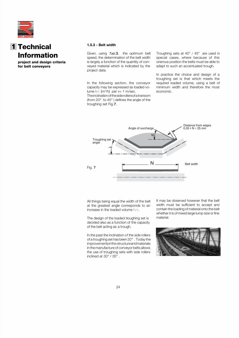
1.5.3 - Belt width
Given, using Tab. 3 , the optimum belt
speed, the determination of the belt widthis largely a function of the quantity of con-veyed material which is indicated by theproject data.
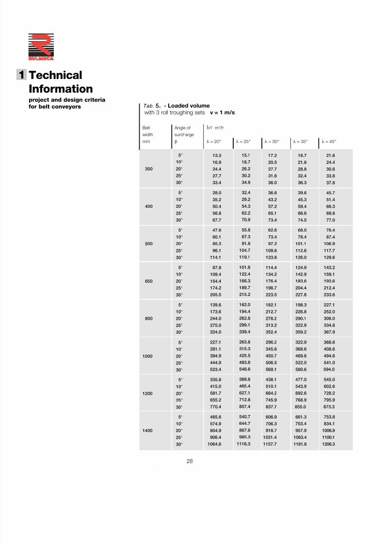
In the following section, the conveyorcapacity may be expressed as loaded vo-lume I VT [m3 /h] per v= 1 m/sec.
The inclination of the side rollers of a transom(from 20 ° to 45 ° ) defines the angle of thetroughing set Fig. 7 .
Fig. 7
All things being equal the width of the beltat the greatest angle corresponds to anincrease in the loaded volume I VT .
The design of the loaded troughing set isdecided also as a function of the capacityof the belt acting as a trough.
In the past the inclination of the side rollersof a troughing set has been 20 ° . Today theimprovements in the structure and materialsin the manufacture of conveyor belts allowsthe use of troughing sets with side rollersinclined at 30 ° / 35 ° .
Troughing sets at 40 ° / 45 ° are used in
special cases, where because of thisonerous position the belts must be able toadapt to such an accentuated trough.
In practice the choice and design of atroughing set is that which meets therequired loaded volume, using a belt of minimum width and therefore the mosteconomic.
N
β
λ
Troughing setangle
Angle of surchargeDistance from edges0,05 x N + 25 mm
Belt width
It may be observed however that the beltwidth must be sufficient to accept andcontain the loading of material onto the beltwhether it is of mixed large lump size or finematerial.
7/27/2019 31801183 Idler Roller
http://slidepdf.com/reader/full/31801183-idler-roller 27/308
25
For belts with higher breaking loads than those indicated in the table, it is advisable to consult the actual belt manufacturer.
In the calculation of belt dimensions onemust take into account the minimum values
of belt width as a function of the beltbreaking load and the side roller inclinationas shown in Tab. 4 .
Loaded volume IM The volumetric load on the belt is given bythe formula:
Iv IM = _______ [ m 3 /h ]
qs
where:Iv = load capacity of the belt [ t/h ]qs = specific weight of the material
Also defined as:IM
I VT = _______ [ m 3 /h ] v
where the loaded volume is expressedrelevant to the speed of 1 mtr/sec.
Tab. 4 - Minimum belt width in relation to belt breaking load and roller inclinations.
Breaking load Belt width
λ= 20/25 ° λ= 30/35 ° λ= 45 °
N/mm mm
250 400 400 —
315 400 400 450
400 400 400 450
500 450 450 500
630 500 500 600
800 500 600 650
1000 600 650 800
1250 600 800 1000
1600 600 800 1000
It may be determined from Tab. 5a-b-c-dthat the chosen belt width satisfies therequired loaded volume IM as calculatedfrom the project data, in relation to thedesign of the troughing sets, the rollerinclination, the angle of material surchargeand to belt speed.
7/27/2019 31801183 Idler Roller
http://slidepdf.com/reader/full/31801183-idler-roller 28/308
26
Technical
Informationproject and design criteriafor belt conveyors
1
®
Belt Angle of I VT m 3 /h
width surcharge
mm β λ = 0 °
5 °
10 °
1600 20 °
25 °
30 °
5 °
10 °
1800 20 °
25 °
30 °
5 °
10 °
2000 20 °
25 °
30 °
5 °
10 °
2200 20 °
25 °
30 °
5 °
10 °
2400 20 °
25 °
30 °
5 °
10 °
2600 20 °
25 °
30 °
5 °
10 °
2800 20 °
25 °
30 °
5 °
10 °
3000 20 °
25 °
30 °
Belt Angle of I VT m 3 /h
width surcharge
mm β λ = 0 °
5° 3.6
10 ° 7.5
300 20 ° 15.4
25 ° 20.1
30 ° 25.2
5° 7.5
10 ° 15.1
400 20 ° 31.3
25 ° 39.9
30 ° 50.0
5° 12.6
10 ° 25.2
500 20 ° 52.2
25 ° 66.6
30 ° 83.5
5° 22.3
10 ° 45.0
650 20 ° 93.2
25 ° 119.5
30 ° 149.4
5° 35.2
10 ° 70.9
800 20 ° 146.5
25 ° 187.5
30 ° 198.3
5° 56.8
10 ° 114.4
1000 20 ° 235.8
25 ° 301.6
30 ° 377.2
5° 83.8
10 ° 167.7
1200 20 ° 346.3
25 ° 436.6
30 ° 554.0
5° 115.5
10 ° 231.4
1400 20 ° 478.0
25 ° 611.6
30 ° 763.2
152.6
305.6
630.7
807.1
1008.7
194.7
389.8
804.9
1029.9
1287.0
241.9
484.2
1000.0
1279.4
1599.1
295.5
591.1
1220.41560.8
1949.4
353.1
706.3
1458.3
1865.1
2329.5
415.9
831.9
1717.9
2197.1
2744.1
484.0
968.0
1998.7
2556.3
3192.8
557.1
1114.2
2300.4
2942.2
3674.8
Tab. 5 a - Loaded volumewith flat roller sets v = 1 m/s
β
7/27/2019 31801183 Idler Roller
http://slidepdf.com/reader/full/31801183-idler-roller 29/308
27
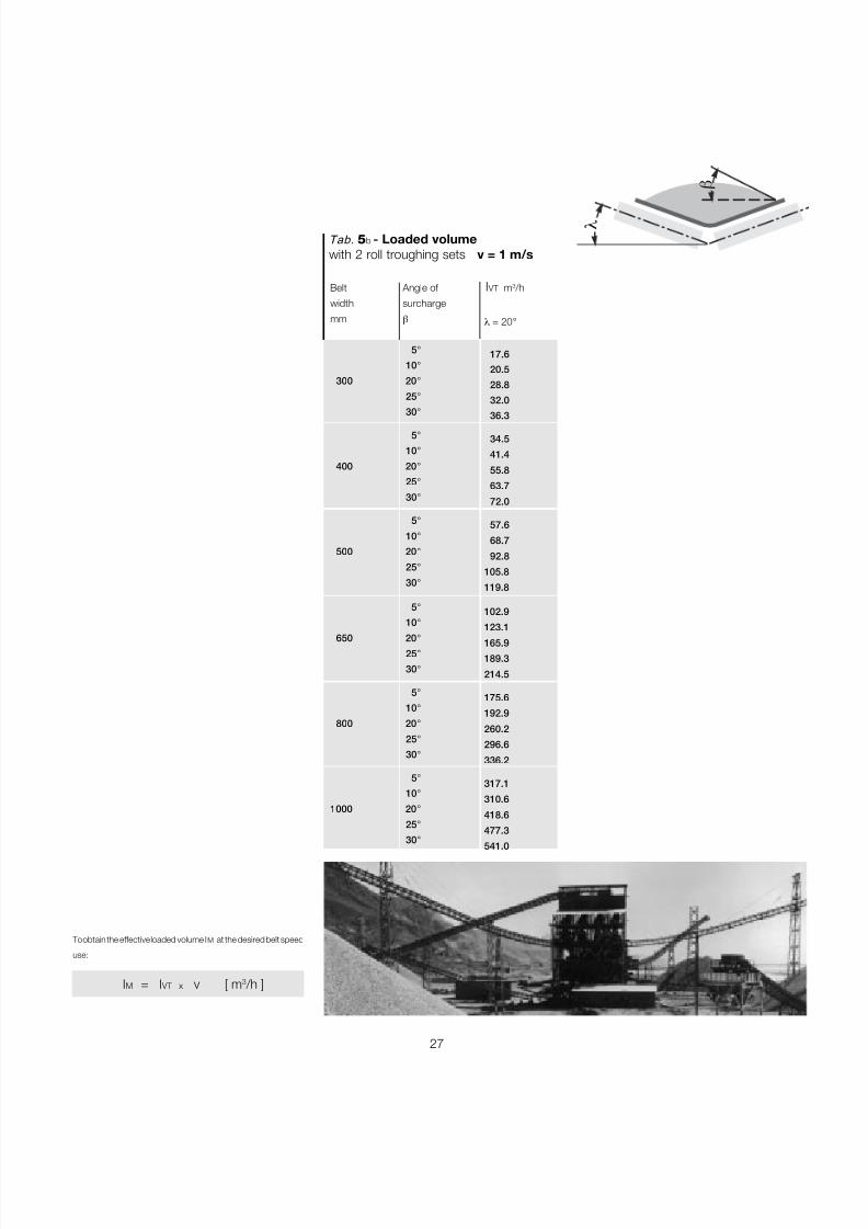
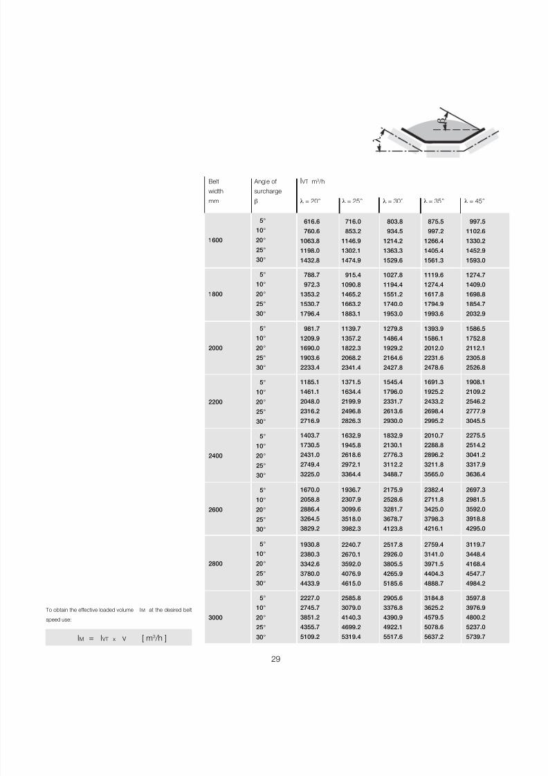
To obtain the effective loaded volume I M at the desired belt speed
use:
IM = I VT x v [ m 3 /h ]
Belt Angle of I VT m 3 /h
width surcharge
mm β
5°
10 °
300 20 °
25 °
30 °
5°
10 °
400 20 °
25 °
30 °
5°
10 °
500 20 °
25 °
30 °
5°
10 °
650 20 °
25 °
30 °
5°
10 °
800 20 °
25 °
30 °
5°
10 °
1000 20 °
25 °
30 °
λ = 20 °
17.6
20.5
28.8
32.0
36.3
34.5
41.4
55.8
63.7
72.0
57.6
68.7
92.8
105.8
119.8
102.9
123.1
165.9
189.3
214.5
175.6
192.9
260.2
296.6
336.2
317.1
310.6
418.6
477.3
541.0
Tab. 5 b - Loaded volumewith 2 roll troughing sets v = 1 m/s
β
λ
7/27/2019 31801183 Idler Roller
http://slidepdf.com/reader/full/31801183-idler-roller 30/308
28
Technical
Informationproject and design criteriafor belt conveyors
1
®
21.6
24.4
30.6
33.8
37.8
45.7
51.4
66.3
69.8
77.0
78.4
87.4
106.9
117.7
129.6
143.2
159.1
193.6212.4
233.6
227.1
252.0
306.0
334.8
367.9
368.6
408.6
494.6
541.0
594.0
545.0
602.6
728.2
795.9
873.3
753.8
834.1
1006.9
1100.1
1206.3
18.7
21.6
28.8
32.4
36.3
39.6
45.3
59.4
66.6
74.5
68.0
78.4
101.1
112.6
126.0
124.9
142.9
183.6204.4
227.8
198.3
226.8
290.1
322.9
359.2
322.9
368.6
469.8
522.0
580.6
477.0
543.9
692.6
768.9
855.0
661.3
753.4
957.9
1063.4
1181.8
17.2
20.5
27.7
31.6
36.0
36.6
43.2
57.2
65.1
73.4
62.6
73.4
97.2
109.8
123.8
114.4
134.2
176.4198.7
223.5
182.1
212.7
278.2
313.2
352.4
296.2
345.6
450.7
506.5
569.1
438.1
510.1
664.2
745.9
837.7
606.9
706.3
918.7
1031.4
1157.7
15.1
18.7
26.2
30.2
34.9
32.4
29.2
54.3
62.2
70.9
55.8
67.3
91.8
104.7
119.1
101.8
122.4
166.3189.7
215.2
162.0
194.4
262.8
299.1
339.4
263.8
315.3
425.5
483.8
548.6
389.8
465.4
627.1
712.8
807.4
540.7
644.7
867.6
985.3
1116.3
13.3
16.9
24.4
27.7
33.4
28.0
35.2
50.4
56.8
67.7
47.8
60.1
85.3
96.1
114.1
87.8
109.4
154.4174.2
205.5
139.6
173.6
244.0
275.0
324.0
227.1
281.1
394.9
444.9
523.4
335.8
415.0
581.7
655.2
770.4
465.8
574.9
804.9
906.4
1064.8
Belt Angle of I VT m 3 /h
width surcharge
mm β λ = 20 ° λ = 25 ° λ = 30 ° λ = 35 ° λ = 45 °
5 °
10 °
300 20 °
25 °
30 °
5 °
10 °
400 20 °
25 °
30 °
5 °
10 °
500 20 °
25 °
30 °
5 °
10 °
650 20 °25 °
30 °
5 °
10 °
800 20 °
25 °
30 °
5 °
10 °
1000 20 °
25 °
30 °
5 °
10 °
1200 20 °
25 °
30 °
5 °
10 °
1400 20 °
25 °
30 °
Tab. 5 c - Loaded volume with 3 roll troughing sets v = 1 m/s
7/27/2019 31801183 Idler Roller
http://slidepdf.com/reader/full/31801183-idler-roller 31/308
29
997.5
1102.6
1330.2
1452.9
1593.0
1274.7
1409.0
1698.8
1854.7
2032.9
1586.5
1752.8
2112.1
2305.8
2526.8
1908.1
2109.2
2546.22777.9
3045.5
2275.5
2514.2
3041.2
3317.9
3636.4
2697.3
2981.5
3592.0
3918.8
4295.0
3119.7
3448.4
4168.4
4547.7
4984.2
3597.8
3976.9
4800.2
5237.0
5739.7
875.5
997.2
1266.4
1405.4
1561.3
1119.6
1274.4
1617.8
1794.9
1993.6
1393.9
1586.1
2012.0
2231.6
2478.6
1691.3
1925.2
2433.22698.4
2995.2
2010.7
2288.8
2896.2
3211.8
3565.0
2382.4
2711.8
3425.0
3798.3
4216.1
2759.4
3141.0
3971.5
4404.3
4888.7
3184.8
3625.2
4579.5
5078.6
5637.2
803.8
934.5
1214.2
1363.3
1529.6
1027.8
1194.4
1551.2
1740.0
1953.0
1279.8
1486.4
1929.2
2164.6
2427.8
1545.4
1796.0
2331.72613.6
2930.0
1832.9
2130.1
2776.3
3112.2
3488.7
2175.9
2528.6
3281.7
3678.7
4123.8
2517.8
2926.0
3805.5
4265.9
5185.6
2905.6
3376.8
4390.9
4922.1
5517.6
716.0
853.2
1146.9
1302.1
1474.9
915.4
1090.8
1465.2
1663.2
1883.1
1139.7
1357.2
1822.3
2068.2
2341.4
1371.5
1634.4
2199.92496.8
2826.3
1632.9
1945.8
2618.6
2972.1
3364.4
1936.7
2307.9
3099.6
3518.0
3982.3
2240.7
2670.1
3592.0
4076.9
4615.0
2585.8
3079.0
4140.3
4699.2
5319.4
To obtain the effective loaded volume I M at the desired belt
speed use:
IM = I VT x v [ m 3 /h ]
Belt Angle of I VT m 3 /h
width surcharge
mm β λ = 20 ° λ = 25 ° λ = 30 ° λ = 35 ° λ = 45 °
5°
10 °
1600 20 °
25 °
30 °
5°
10 °
1800 20 °
25 °
30 °
5°
10 °
2000 20 °
25 °
30 °
5°
10 °
2200 20 °25 °
30 °
5°
10 °
2400 20 °
25 °
30 °
5°
10 °
2600 20 °
25 °
30 °
5°
10 °
2800 20 °
25 °
30 °
5°
10 °
3000 20 °
25 °
30 °
616.6
760.6
1063.8
1198.0
1432.8
788.7
972.3
1353.2
1530.7
1796.4
981.7
1209.9
1690.0
1903.6
2233.4
1185.1
1461.1
2048.02316.2
2716.9
1403.7
1730.5
2431.0
2749.4
3225.0
1670.0
2058.8
2886.4
3264.5
3829.2
1930.8
2380.3
3342.6
3780.0
4433.9
2227.0
2745.7
3851.2
4355.7
5109.2
β
λ
7/27/2019 31801183 Idler Roller
http://slidepdf.com/reader/full/31801183-idler-roller 32/308
30
Technical
Informationproject and design criteriafor belt conveyors
1
®
1679.7
1846.0
2185.2
2381.7
2595.9
2049.1
2251.1
2661.8
2901.2
3162.2
2459.8
2703.2
3185.2
3471.8
3784.3
2899.4
3186.3
3755.14092.8
4461.4
3379.3
3713.7
4372.2
4765.6
5194.4
3863.5
4245.8
5018.4
5469.8
5962.3
236.5
260.2
313.9
342.0
372.9
388.8
427.3
510.4
556.2
606.2
573.1
630.0
751.3
816.6
892.4
797.4
876.6
1041.41135.0
1237.3
1075.3
1181.8
1371.9
1495.0
1629.7
1343.1
1476.0
1749.6
1906.9
2078.6
Belt Angle of I VT m 3 /h
width surcharge
mm β λλλλλ1 30 ° λλλλλ2 60 °
5°
10 °
800 20 °
25 °
30 °
5°
10 °1000 20 °
25 °
30 °
5°
10 °
1200 20 °
25 °
30 °
5°
10 °
1400 20 °
25 °
30 °
5°
10 °
1600 20 °
25 °
30 °
5°
10 °
1800 20 °
25 °
30 °
Belt Angle of I VT m 3 /h
width surcharge
mm β λ λ λ λ λ1 30 ° λλλλλ2 60 °
5 °
10 °
2000 20 °
25 °
30 °
5 °
10 °
2200 20 °
25 °
30 °
5 °
10 °
2400 20 °
25 °
30 °
5 °
10 °
2600 20 °
25 °
30 °
5 °
10 °
2800 20 °
25 °
30 °
5 °
10 °
3000 20 °
25 °
30 °
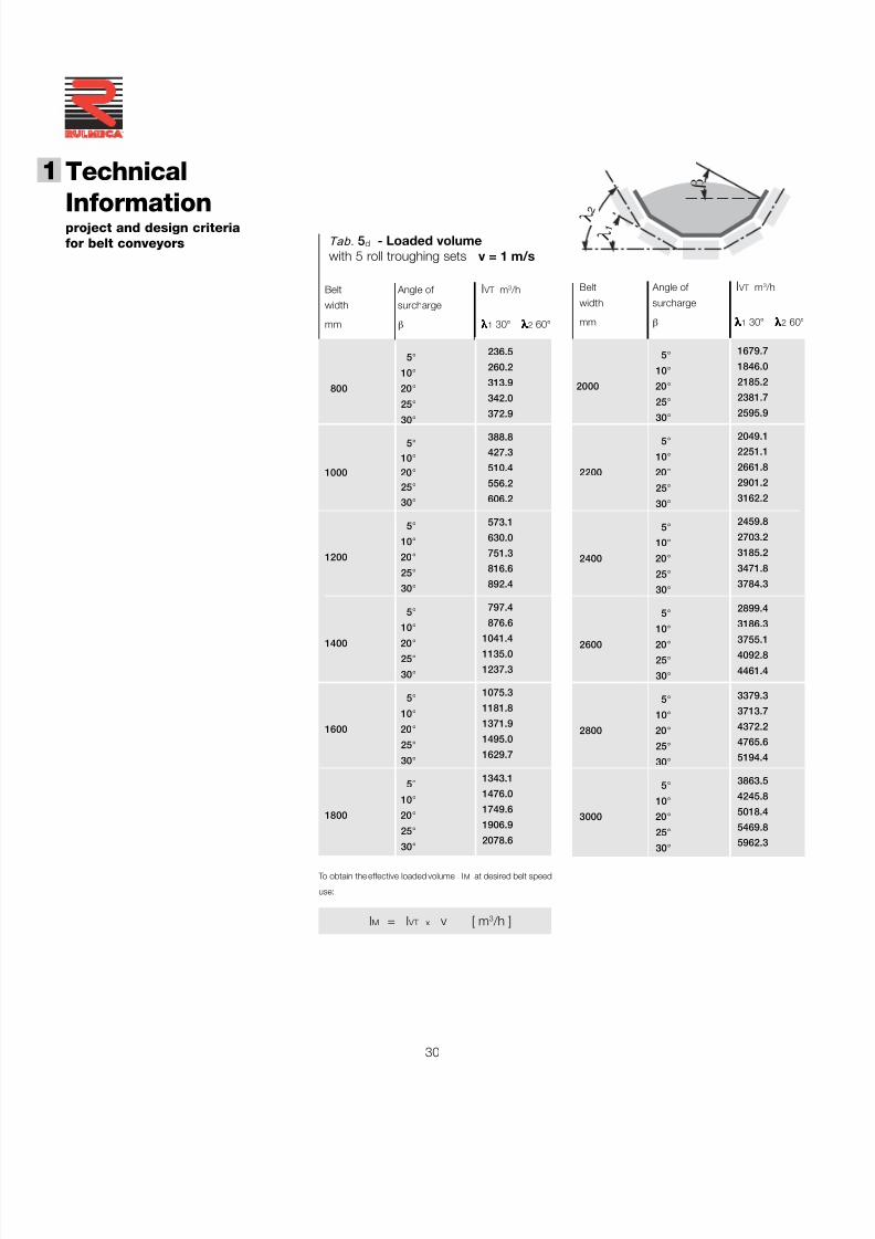
Tab. 5 d - Loaded volumewith 5 roll troughing sets v = 1 m/s
To obtain the effective loaded volume I M at desired belt speed
use:
IM = I VT x v [ m 3 /h ]
β
λ 1
λ 2
7/27/2019 31801183 Idler Roller
http://slidepdf.com/reader/full/31801183-idler-roller 33/308
31
In general it is necessary to take into accountthe nature of the feed to the conveyor,whether it is constant and regular, byintroducing a correction factor K 1 its valuebeing :
- K 1 = 1 regular feed
- K 1 = 0.95 irregular feed
- K 1 = 0.90 ÷ 0.80 most irregular feed.
If one considers that the load may becorrected by the above factors the effecti-ve loaded volume at the required speed isgiven by :
IM = I VM x v [m 3 /h]
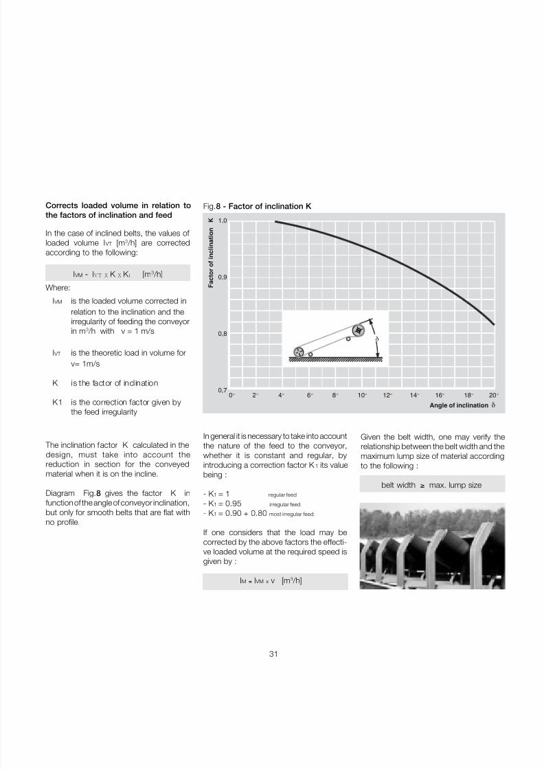
In the case of inclined belts, the values of loaded volume I VT [m3 /h] are correctedaccording to the following:
I VM = IVT X K X K 1 [m3 /h]
Where:
I VM is the loaded volume corrected inrelation to the inclination and theirregularity of feeding the conveyorin m 3 /h with v = 1 m/s
I VT is the theoretic load in volume forv= 1m/s
K is the factor of inclination
K1 is the correction factor given bythe feed irregularity
0°
2°
4°
6°
8°
10°
12°
14°
16°
18°
20°
Angle of inclination δ
F a c
t o r o
f i n c
l i n a
t i o n
K 1,0
0,9
0,8
0,7
δ
Fig.8 - Factor of inclination K Corrects loaded volume in relation tothe factors of inclination and feed
The inclination factor K calculated in thedesign, must take into account thereduction in section for the conveyedmaterial when it is on the incline.
Diagram Fig. 8 gives the factor K infunction of the angle of conveyor inclination,but only for smooth belts that are flat withno profile.
Given the belt width, one may verify therelationship between the belt width and themaximum lump size of material accordingto the following :
belt width ≥ max. lump size
7/27/2019 31801183 Idler Roller
http://slidepdf.com/reader/full/31801183-idler-roller 34/308
32
Technical
Informationproject and design criteriafor belt conveyors
1
®
The roller frame with fixed supports, withthree rollers of equal length, support thebelt well with a uniform distribution of forces
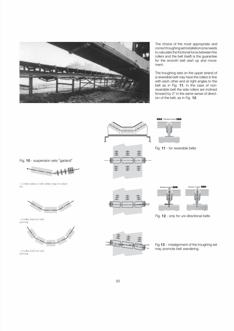
and load sharing. The inclination of the side roller varies from20 ° up to 45 ° for belts of 400 mm width upto 2200mm and over.
The suspended sets of “garland” designare used incorporating impact rollers toaccept the impact under the load hopper,and also in use along the conveyor upperand lower strands where large loads maybe carried or on very high performanceconveyors.
The troughing sets are generally designedand manufactured according to internat-ional unified standards.
The drawings illustrate the more commonarrangements.
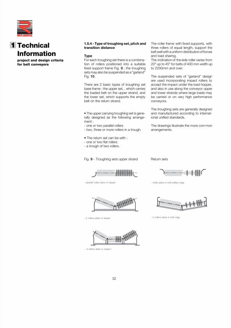
1 1.5.4 - Type of troughing set, pitch andtransition distance
TypeFor each troughing set there is a combina-tion of rollers positioned into a suitablefixed support frame Fig. 9 ; the troughingsets may also be suspended as a “garland”Fig. 10 .
There are 2 basic types of troughing setbase frame : the upper set, , which carriesthe loaded belt on the upper strand, andthe lower set, which supports the emptybelt on the return strand.
• The upper carrying troughing set is gene-rally designed as the following arrange-ment :- one or two parallel rollers- two, three or more rollers in a trough.
• The return set can be with :- one or two flat rollers- a trough of two rollers.
- 3 rollers plain or impac t
- roller plain or with rubber rings- parallel roller plain or impact
- 2 rollers plain or with rings- 2 rollers plain or impact
Fig. 9 - Troughing sets upper strand Return sets
7/27/2019 31801183 Idler Roller
http://slidepdf.com/reader/full/31801183-idler-roller 35/308
33
Fig. 12 - only for uni-directional belts
Fig.13 - misalignment of the troughing setmay promote belt wandering.
The choice of the most appropriate andcorrect troughing set installation (one needsto calculate the frictional force between the
rollers and the belt itself) is the guaranteefor the smooth belt start up and move-ment.
The troughing sets on the upper strand of a reversible belt may have the rollers in linewith each other and at right angles to thebelt as in Fig. 11 ; in the case of non-reversible belt the side rollers are inclinedforward by 2 ° in the same sense of direct-ion of the belt, as in Fig. 12 .
Direction of travel
Fig. 11 - for reversible belts
Direction of travel Direction of travel
- 3 rollers p lain for loadcarrying
- 2 rollers plain or with rubber rings for returnse t
- 5 rollers p lain for loadcarrying
Fig. 10 - suspension sets "garland"
7/27/2019 31801183 Idler Roller
http://slidepdf.com/reader/full/31801183-idler-roller 36/308
34
Technical
Informationproject and design criteriafor belt conveyors
1
®
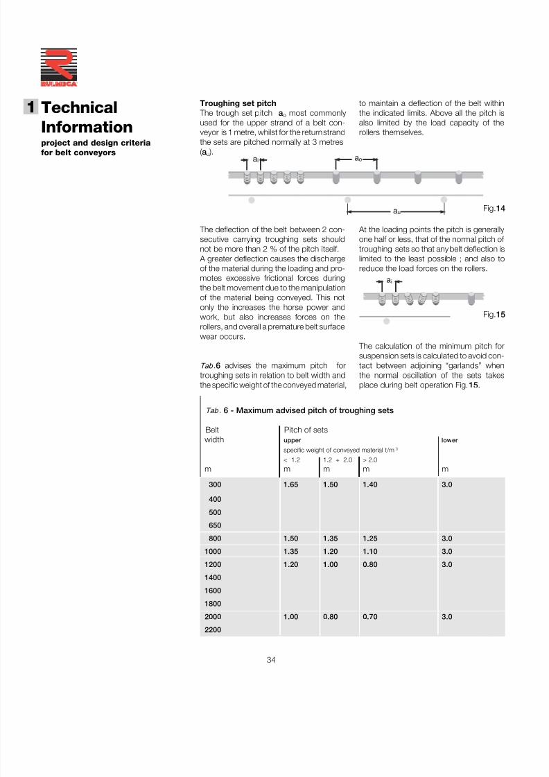
a i
Tab . 6 - Maximum advised pitch of troughing sets
Belt Pitch of setswidth upper lower
specific weight of conveyed material t/m 3
< 1.2 1.2 ÷ 2.0 > 2.0
m m m m m
300 1.65 1.50 1.40 3.0
400
500
650
800 1.50 1.35 1.25 3.0
1000 1.35 1.20 1.10 3.0
1200 1.20 1.00 0.80 3.0
1400
1600
1800
2000 1.00 0.80 0.70 3.0
2200
to maintain a deflection of the belt withinthe indicated limits. Above all the pitch isalso limited by the load capacity of the
rollers themselves.
At the loading points the pitch is generallyone half or less, that of the normal pitch of troughing sets so that any belt deflection islimited to the least possible ; and also toreduce the load forces on the rollers.
The calculation of the minimum pitch forsuspension sets is calculated to avoid con-tact between adjoining “garlands” whenthe normal oscillation of the sets takesplace during belt operation Fig. 15 .
Troughing set pitch The trough set pitch a o most commonlyused for the upper strand of a belt con-
veyor is 1 metre, whilst for the return strandthe sets are pitched normally at 3 metres(a u ).
The deflection of the belt between 2 con-secutive carrying troughing sets shouldnot be more than 2 % of the pitch itself.
A greater deflection causes the dischargeof the material during the loading and pro-motes excessive frictional forces duringthe belt movement due to the manipulationof the material being conveyed. This notonly the increases the horse power andwork, but also increases forces on therollers, and overall a premature belt surfacewear occurs.
Tab .6 advises the maximum pitch fortroughing sets in relation to belt width andthe specific weight of the conveyed material,
a i a o
a u Fig.14
Fig.15
7/27/2019 31801183 Idler Roller
http://slidepdf.com/reader/full/31801183-idler-roller 37/308
35
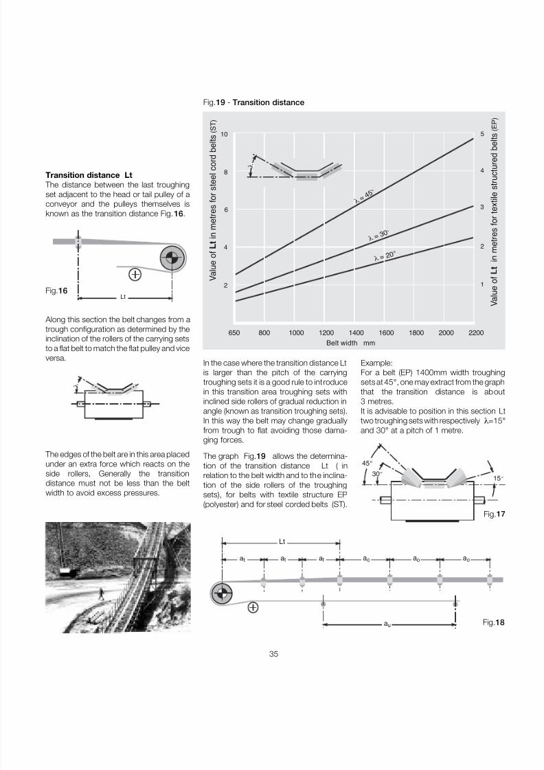
Lt
a oa t a t a t a o a o
a u
Transition distance Lt The distance between the last troughingset adjacent to the head or tail pulley of aconveyor and the pulleys themselves isknown as the transition distance Fig. 16 .
Fig.16
Along this section the belt changes from atrough configuration as determined by theinclination of the rollers of the carrying setsto a flat belt to match the flat pulley and viceversa.
The edges of the belt are in this area placedunder an extra force which reacts on theside rollers, Generally the transitiondistance must not be less than the beltwidth to avoid excess pressures.
Lt
Example:For a belt (EP) 1400mm width troughingsets at 45 °, one may extract from the graphthat the transition distance is about3 metres.It is advisable to position in this section Ltwo troughing sets with respectively λ=15and 30 ° at a pitch of 1 metre.
In the case where the transition distance Ltis larger than the pitch of the carryingtroughing sets it is a good rule to introducein this transition area troughing sets withinclined side rollers of gradual reduction inangle (known as transition troughing sets).In this way the belt may change graduallyfrom trough to flat avoiding those dama-ging forces.
The graph Fig.19 allows the determina-tion of the transition distance Lt ( inrelation to the belt width and to the inclina-tion of the side rollers of the troughingsets), for belts with textile structure EP(polyester) and for steel corded belts (ST).
λ
4 2
2 1
650 800 1000 1200 1400 1600 1800 2000 2200Belt width mm
V a
l u e
o f L t i n m e
t r e s
f o r s
t e e
l c o r d
b e
l t s ( S T )
V a
l u e o
f L t i n m e
t r e s
f o r
t e x
t i l e s
t r u c
t u r e
d b e
l t s ( E P )
λ = 2 0
°
λ = 3 0
°
λ = 4 5
°
6
8
10
3
4
5
λ
Fig.19 - Transition distance
Fig.1
30 °
15
45 °
Fig.1
7/27/2019 31801183 Idler Roller
http://slidepdf.com/reader/full/31801183-idler-roller 38/308
7/27/2019 31801183 Idler Roller
http://slidepdf.com/reader/full/31801183-idler-roller 39/308
37
When it is necessary to calculate theforces on a variable altitude belt conveyorit may be seen that the total tangential
force is made up from forces Fa (tangentialforce to move the belt, upper strand) andthe lesser force Fr (tangential force onreturn strand)all necessary to move a sin-gle uniform section of the belt that comp-rises the conveyor (Fig. 20 ) thus we have:
FU=(Fa 1+Fa 2+Fa 3...)+(Fr1+Fr 2+Fr 3...)
Where:Fa = tangential force to move a single
section of the belt upper strandFr = tangential force to move a single
section of the belt lower strand
Fa = [ L x Cq x Ct x f ( qb + q G + q RO ) ± ( qG + q b ) x H ] x 0.981 [daN]
Fr = [ L x Cq x Ct x f ( qb + q RU ) ± ( q b x H) ] x 0.981 [daN]
Using the indication (+) for belt sections that rise(-) for sections that fall
Therefore the tangential force Fa and Fr will be given by:
Driving powerNoting the total tangential force at theperiphery of the drive pulley, the belt speedand the efficiency ( η ) of the reductiongear, the minimum necessary drivingpower is :
FU x vP = ———— [kW]
100 x ηηηηη
L 4L 3L 2L 1
H 1 H
2 H 3
Fig.20 - Varying altitude profile
7/27/2019 31801183 Idler Roller
http://slidepdf.com/reader/full/31801183-idler-roller 40/308
38
Technical
Informationproject and design criteriafor belt conveyors
1
®
Passive resistance The passive resistance is expressed by acoefficient which is dependant on the length
of the belt conveyor, ambient temperature,speed, type of maintenance, cleanlinessand fluidity of movement, internal friction of the conveyed material, and to the convey-or inclinations.
Tab . 7 - Coefficient of fixed resistance
Centres Cqm
10 4.5
20 3.2
30 2.6
40 2.2
50 2.1
60 2.0
80 1.8
100 1.7
150 1.5
200 1.4
250 1.3
300 1.2
400 1.1
500 1.05
1000 1.03
Rotating parts and material
with sta nda rd internal friction
Rotat ing parts and material
with high internal friction in
difficult w orking cond itions
Rotat ing parts of a conveyor
in descent with a brake motor
and /or generator
Horizontal belt conveyor
rising and gently falling
velocità m/s
1 2 3 4 5 6
0, 0160 0, 0165 0, 0170 0, 0180 0, 0200 0, 0220
da 0,023 a 0,027
da 0,012 a 0,016
Tab. 8 - Coefficient of passive resistance given by temperature
Temperature °C + 20 ° + 10 ° 0 - 10 ° - 20 ° - 30 °
Fa c tor C t 1 1,01 1,04 1,10 1,16 1,27
Tab. 9 - Coefficient of internal friction f of materials and of the rotating parts
speed m/s
7/27/2019 31801183 Idler Roller
http://slidepdf.com/reader/full/31801183-idler-roller 41/308
39
Belt weight per linear metre q b
The total belt weight qb may be determin-ed adding the belt core weight, to that of
the belt covers upper and lower allowingabout 1.15 Kg/m 2 for each mm of thick-ness of the covers themselves.
Tab. 10 - Belt core weight q bn
Belt Roller diameter mm
width 89 108 133 159 194
Pprs Ppri Pprs Ppri Pprs Ppri Pprs Ppri Pprs Pprimm Kg
400 — — —
500 5.1 3.7 —
650 9.1 6.5 —800 10.4 7.8 16.0 11.4 —
1000 11.7 9.1 17.8 13.3 23.5 17.5
1200 20.3 15.7 26.7 20.7 —
1400 29.2 23.2 —
1600 31.8 25.8 —
1800 47.2 38.7 70.5 55.5
2000 50.8 42.2 75.3 60.1
2200 — — — —
In Tab . 11 the approximate weights of rotating parts of an upper transom trough-ing set and a lower flat return set areindicated.
The weight of the upper rotating partsq RO and lower q RU is given by :
Pprsq RO = _________ [kg/m]
a o
where :Pprs = weight of upper rotating
partsa o =upper troughing set pitch
Ppriq RU = _________ [kg/m]
a u
where :Ppri = weight of lower rotating
partsa u = return set roller pitch
The weights are indicative of the b elt core with textile or meta llic inserts in relation to the c lass o f resistanc e.
Breaking force Belt with Belt with metal
of belt textile inserts (EP) inserts Steel Cord (ST)N/mm Kg/m 2 Kg/m 2
200 2.0 -
250 2.4 -
315 3.0 -
400 3.4 -
500 4.6 5.5
630 5.4 6.0
800 6.6 8.5
1000 7.6 9.5
1250 9.3 10.41600 - 13.5
2000 - 14.8
2500 - 18.6
3150 - 23.4
Tab. 11 - Weight of rotating parts of the rollers (upper/lower)
7/27/2019 31801183 Idler Roller
http://slidepdf.com/reader/full/31801183-idler-roller 42/308
40
Technical
Informationproject and design criteriafor belt conveyors
1
®
Belt tensionIt is necessary to consider the differenttensions that must be verified in a conveyor
with a powered belt system.
Tensions T 1 e T 2 The total tangential force F U at the pulleycircumference corresponds to the differ-ences between tensionsT 1 (tight side) and
T 2 (output side). From these is derived the
necessary torque to begin to move the beltand transmit power.
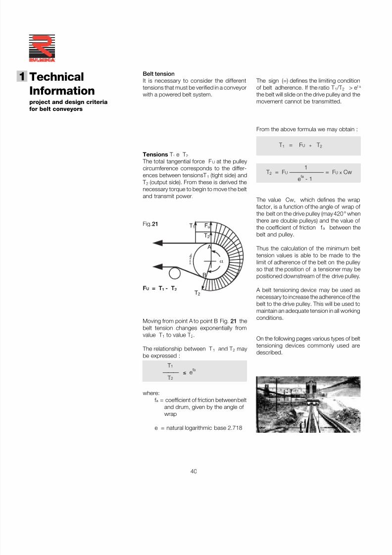
Fig.21
Moving from point A to point B Fig. 21 thebelt tension changes exponentially fromvalue T 1 to value T 2.
The relationship between T 1 and T 2 maybe expressed :
T 1——— ≤ e fa
T 2
where:f a = coefficient of friction between belt
and drum, given by the angle of wrap
e = natural logarithmic base 2.718
The sign (=) defines the limiting conditionof belt adherence. If the ratio T 1 /T 2 > e f a
the belt will slide on the drive pulley and themovement cannot be transmitted.
From the above formula we may obtain :
T 1 = F U + T 2
1T 2 = F U —————— = F U x Cw
e fa - 1
The value Cw, which defines the wrapfactor, is a function of the angle of wrap of the belt on the drive pulley (may 420 ° whenthere are double pulleys) and the value of the coefficient of friction f a between thebelt and pulley.
Thus the calculation of the minimum belttension values is able to be made to thelimit of adherence of the belt on the pulleyso that the position of a tensioner may bepositioned downstream of the drive pulley.
A belt tensioning device may be used asnecessary to increase the adherence of thebelt to the drive pulley. This will be used tomaintain an adequate tension in all workingconditions.
On the following pages various types of belttensioning devices commonly used aredescribed.
FU = T 1 - T 2
T1
T2
T2
Fu
A
B
α
7/27/2019 31801183 Idler Roller
http://slidepdf.com/reader/full/31801183-idler-roller 43/308
41
Given the values T 1 and T 2 ,we may analysethe belt tensions in other areas that are
critical to the conveyor. These are :
- Tension T 3 relative to the slack sectionof the return pulley;
- Tension T 0 minimum at tail end, in thematerial loading area;
- Tension Tg of the belt at the point of connection to the tension unit device;
- Tension T max maximum belt tension.
T0 =T3
T3
T1
T2
Fig. 22
Tension T 3
As already defined,
T 1 = Fu +T 2 and T 2 = F U x Cw
The tension T 3 that is generated at the beltslackside of the tail pulley ( Fig. 22 ) is givefrom the algebraic sum of the tensions T
and the tangential forces Fr relative to asingle return section of the belt.
Therefore the tension T 3 is given by :
T 3 = T 2 + ( Fr 1 + Fr2 + Fr3 ... ) [daN]
Tab . 12 gives the value of the wrap factorCw in relation to the angle of wrap, the
system of tensioning and the use of thepulley in a lagged or unlagged condition.
fattore di avvolgimento C W
tension unit or counterweight screw tension unit
pulley pulley
unlagged lagged unlagged lagged
180 ° 0.84 0.50 1.2 0.8
200 ° 0.72 0.42 1.00 0.75
210 ° 0.66 0.38 0.95 0.70
220 ° 0.62 0.35 0.90 0.65
240 ° 0.54 0.30 0.80 0.60
380 ° 0.23 0.11 - -
420 ° 0.18 0.08 - -
Angle of wrapα
drivearrangement
Tab. 12 - Wrap factor Cw
T1
T2
T1
T2
T1
T2
7/27/2019 31801183 Idler Roller
http://slidepdf.com/reader/full/31801183-idler-roller 44/308
42
Technical
Informationproject and design criteriafor belt conveyors
1
®
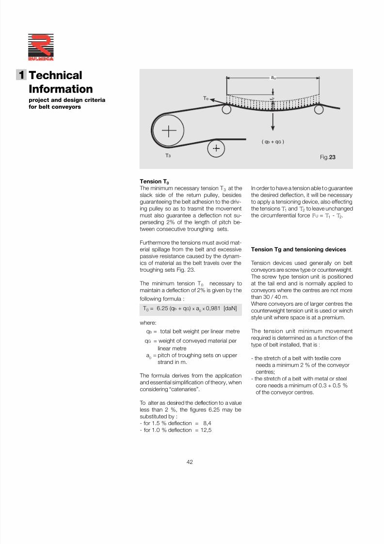
Tension T 0
The minimum necessary tension T 3 at theslack side of the return pulley, besidesguaranteeing the belt adhesion to the driv-ing pulley so as to trasmit the movementmust also guarantee a deflection not su-perseding 2% of the length of pitch be-tween consecutive trounghing sets.
Furthermore the tensions must avoid mat-erial spillage from the belt and excessivepassive resistance caused by the dynam-ics of material as the belt travels over thetroughing sets Fig. 23.
The minimum tension T 0 necessary tomaintain a deflection of 2% is given by the
following formula :
T 0 = 6.25 (q b + q G ) x a 0 x 0,981 [daN]
where:
q b = total belt weight per linear metre
q G = weight of conveyed material perlinear metre
a 0 = pitch of troughing sets on upperstrand in m.
The formula derives from the applicationand essential simplification of theory, whenconsidering “catenaries”.
To alter as desired the deflection to a valueless than 2 %, the figures 6.25 may besubstituted by :- for 1.5 % deflection = 8,4- for 1.0 % deflection = 12,5
In order to have a tension able to guaranteethe desired deflection, it will be necessaryto apply a tensioning device, also effectingthe tensions T1 and T2 to leave unchangedthe circumferential force FU = T1 - T2.
Tension Tg and tensioning devices
Tension devices used generally on beltconveyors are screw type or counterweight.
The screw type tension unit is positionedat the tail end and is normally applied toconveyors where the centres are not morethan 30 / 40 m.Where conveyors are of larger centres thecounterweight tension unit is used or winchstyle unit where space is at a premium.
The tension unit minimum movementrequired is determined as a function of thetype of belt installed, that is :
- the stretch of a belt with textile coreneeds a minimum 2 % of the conveyor
centres;- the stretch of a belt with metal or steelcore needs a minimum of 0.3 + 0.5 %of the conveyor centres.
T3
( q b + q G )
To f r
a o
Fig.23
7/27/2019 31801183 Idler Roller
http://slidepdf.com/reader/full/31801183-idler-roller 45/308
43
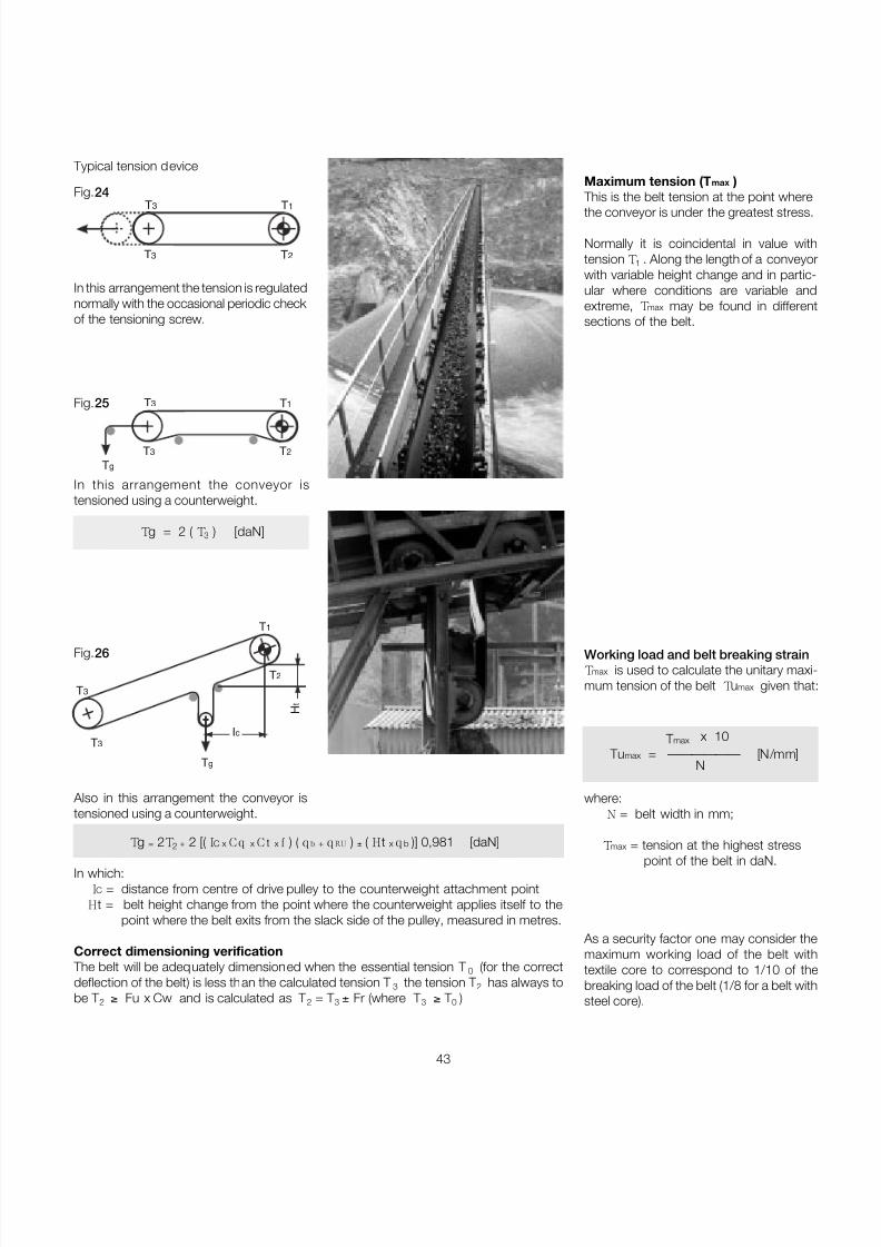
Typical tension deviceMaximum tension (T max )
This is the belt tension at the point where
the conveyor is under the greatest stress.
Normally it is coincidental in value withtension T1 . Along the length of a conveyorwith variable height change and in partic-ular where conditions are variable andextreme, Tmax may be found in differentsections of the belt.
T1
T2T3
T3
In this arrangement the tension is regulatednormally with the occasional periodic check of the tensioning screw.
Also in this arrangement the conveyor istensioned using a counterweight.
T1
T2
T3
T3
Tg
H t
Ic
In this arrangement the conveyor istensioned using a counterweight.
Tg = 2 ( T3 ) [daN]
T1
T2T3
T3
Tg
Fig.24
Fig.25
Fig.26
Tg = 2T2 + 2 [( IC x C q x C t x f ) ( q b + q RU ) ± ( Ht x q b )] 0,981 [daN]
In which: IC = distance from centre of drive pulley to the counterweight attachment point Ht = belt height change from the point where the counterweight applies itself to the
point where the belt exits from the slack side of the pulley, measured in metres.
Correct dimensioning verification The belt will be adequately dimensioned when the essential tension T 0 (for the correctdeflection of the belt) is less than the calculated tension T 3 the tension T 2 has always tobe T 2 ≥ Fu x Cw and is calculated as T 2 = T 3 ± Fr (where T 3 ≥ T 0 )
Working load and belt breaking strainTmax is used to calculate the unitary maxi-mum tension of the belt Tumax given that
T max x 10Tu max = —————— [N/mm]
N
where: N = belt width in mm;
Tmax = tension at the highest stresspoint of the belt in daN.
As a security factor one may consider themaximum working load of the belt withtextile core to correspond to 1/10 of thebreaking load of the belt (1/8 for a belt withsteel core).
7/27/2019 31801183 Idler Roller
http://slidepdf.com/reader/full/31801183-idler-roller 46/308
44
Technical
Informationproject and design criteriafor belt conveyors
1
®
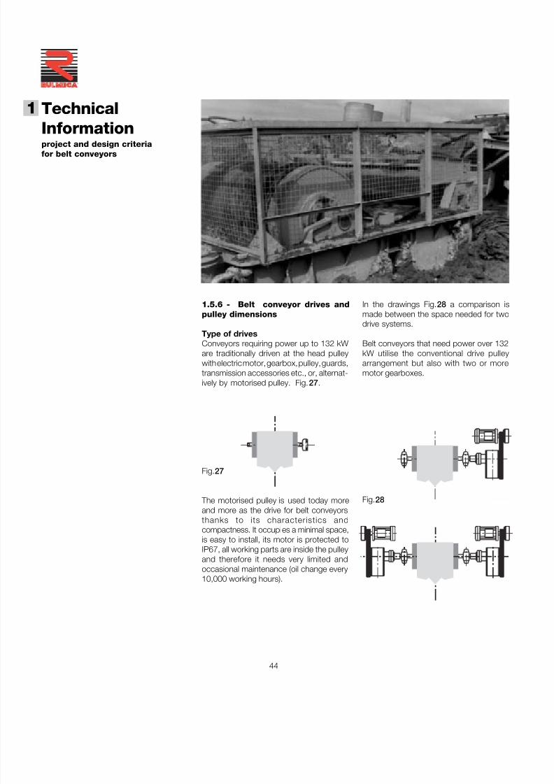
1.5.6 - Belt conveyor drives andpulley dimensions
Type of drivesConveyors requiring power up to 132 kWare traditionally driven at the head pulleywith electric motor, gearbox, pulley, guards,transmission accessories etc., or, alternat-ively by motorised pulley. Fig. 27 .
Fig.27
The motorised pulley is used today moreand more as the drive for belt conveyorsthanks to its characteristics andcompactness. It occupies a minimal space,
is easy to install, its motor is protected toIP67, all working parts are inside the pulleyand therefore it needs very limited andoccasional maintenance (oil change every10,000 working hours).
In the drawings Fig. 28 a comparison ismade between the space needed for twodrive systems.
Belt conveyors that need power over 132kW utilise the conventional drive pulleyarrangement but also with two or moremotor gearboxes.
Fig.28
7/27/2019 31801183 Idler Roller
http://slidepdf.com/reader/full/31801183-idler-roller 47/308
45
belt with textile core EPDIN 22102
Minimum diameters recommended for pulleys in mm up to 100% of the maximum working load as recommendedRMBT ISO bis/3654
belt with steel core ST DIN 22131
Ø motorised return direction Ø motorised return directionpulley pulley change pulley pulley change
N/mm mm drum mm pulley
200 200 160 125 - - -
250 250 200 160 - - -
315 315 250 200 - - -
400 400 315 250 - - -
500 500 400 315 - - -
630 630 500 400 - - -
800 800 630 500 630 500 315
1000 1000 800 630 630 500 315
1250 1250 1000 800 800 630 400
1600 1400 1250 1000 1000 800 500
2000 - - - 1000 800 500
2500 - - - 1250 1000 630
3150 - - - 1250 1000 630
Tab. 13 - Minimum pulley diameters recommended
This table must not be applied to belt conveyors that convey material with a temperatureover +110 °C or for conveyors installed where the ambient temperature is less than- 40 °C.
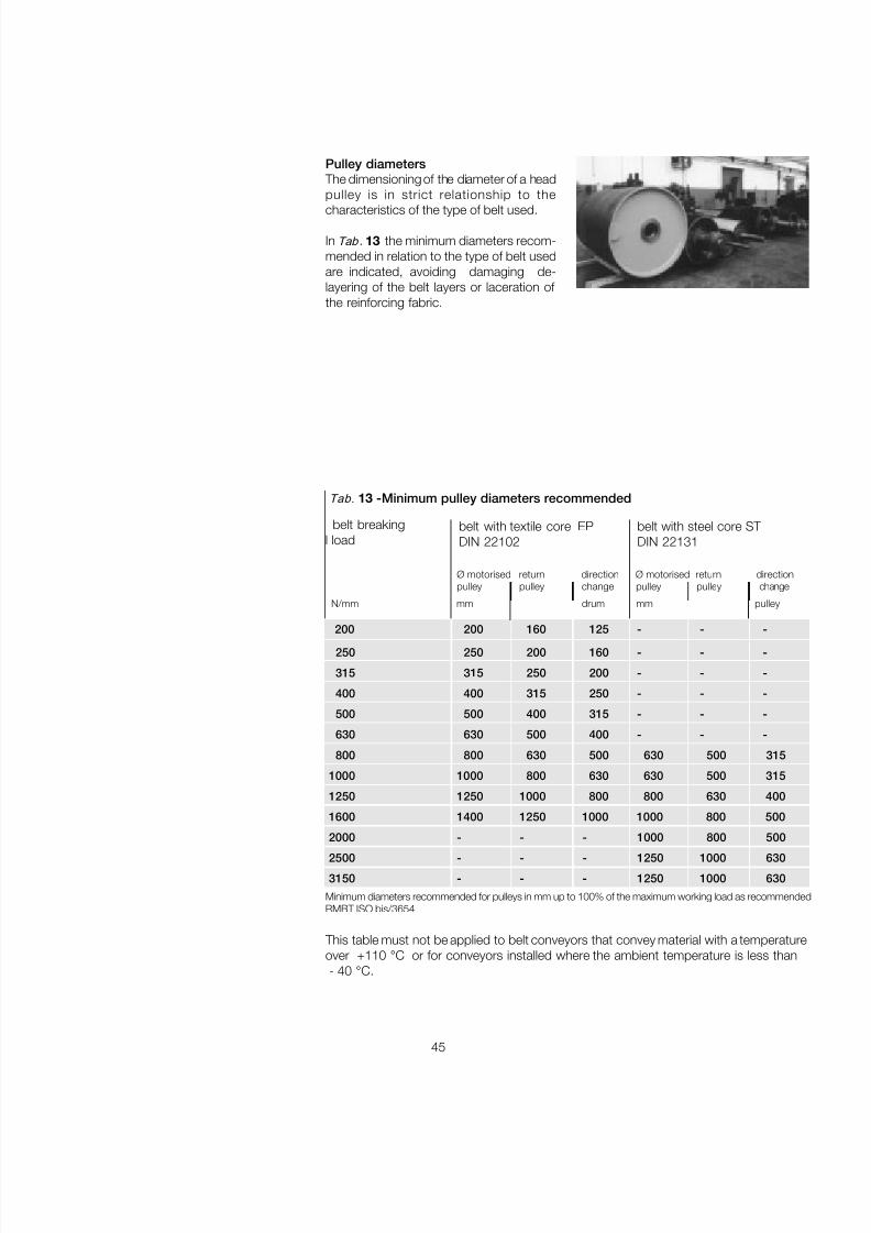
belt breakingl load
Pulley diameters The dimensioning of the diameter of a headpulley is in strict relationship to the
characteristics of the type of belt used.
In Tab . 13 the minimum diameters recom-mended in relation to the type of belt usedare indicated, avoiding damaging de-layering of the belt layers or laceration of the reinforcing fabric.
7/27/2019 31801183 Idler Roller
http://slidepdf.com/reader/full/31801183-idler-roller 48/308
46
Technical
Informationproject and design criteriafor belt conveyors
1
®
The be nding mo ment of the s haft is g ene-rated a s a result of the sum of the vecto r oftensions T 1 and T2 and the weight of thepulley itself q T Fig.29 .
Fig.29
Sizing of the drive pulley The shaft of the drive pulley is subject toalternating flexing and torsion, causing
fatigue failure.
To calculate correct shaft diameter it isnecessary to determine the bendingmoment Mf and the torsion moment Mt.
The dimensioning of the shaft diameterrequires the determination of various values.
These are: the resultant of tensions Cp, thebending moment Mf, torsional momentMt, the ideal bending moment Mif and themodule of resistance W.
Proceeding in order we have:
Cp = ͌ ( T 1 + T 2 )2 + q t2 [daN]
CpMf = ______ x a g [daNm]
2
PMt = ______ x 954,9 [daNm]
n
where:P = absorbed power in kWn = r.p.m. of the drive pulley
T1 T2
qTCp
T1
qT T2
a g
Tab .14 - Suggested value of σσσσσ
Steel type daN/mm 2
38 NCD 12,2
C 40 Tempered 7,82
C 40 Normalised 5,8
Fe 37 Normalised 4,4
Mif = ͌ Mf 2 + 0,75 x Mt2 [daNm]
Mif x 1000W = ___________ [mm 3]
σ amm.
πW = ______ x d 3 [mm 3]
32
from the combination of simultaneousequations we may discover the diameter of the shaft as follows :
d = ͌ W x 32 [mm]_______π
3
Fig.30
7/27/2019 31801183 Idler Roller
http://slidepdf.com/reader/full/31801183-idler-roller 49/308
47
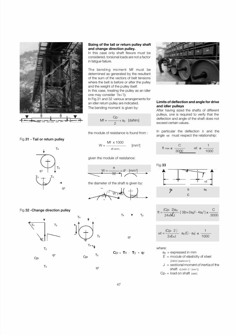
The bending moment is given by:
Cp rMf = ______ x a g [daNm]
2
the module of resistance is found from :
Mf x 1000W = ___________ [mm 3]
σ amm.
given the module of resistance:
πW = ______ x d 3 [mm 3]
32
the diameter of the shaft is given by:
d = ͌ W x 32[mm]_______
π
3
Sizing of the tail or return pulley shaftand change direction pulley.In this case only shaft flexure must be
considered, torsional loads are not a factorin fatigue failure.
Th e be nd ing mo ment Mf mu st bedetermined as generated by the resultantof the sum of the vectors of belt tensionswhere the belt is before or after the pulleyand the weight of the pulley itself.In this case, treating the pulley as an idlerone may consider Tx=TyIn Fig.31 and 32 various arrangements foran idler return pulley are indicated. Limits of deflection and angle for drive
and idler pulleys After having sized the shafts of different
pulleys, one is required to verify that thedeflection and angle of the shaft does notexceed certain values.
In particular the deflection ft and theangle α t must respect the relationship:
C 1ft max ≤ ______ α t ≤ ______
3000 1000
Cp r = Tx + Ty - q T
Tx
Ty
qTCp r
Tx
Cp rTy
qT
Tx Ty
qTqT
Tx
Ty
Ty
qT
Tx
Tx
TyqT
Cp r
qT
Ty Tx
Fig.31 - Tail or return pulley
Fig.32 -Change direction pulley
where:a g = expressed in mmE = module of elasticity of steel
(20600 [daN/mm 2 ])
J = sectional moment of inertia of theshaft (0,0491 D 4 [mm 4 ])
Cp r = load on shaft [daN ]
(Cp r 2)a g C
ft = _________ [ 3(b+2a g )2- 4a g2 ] ≤ _____
24 xExJ 3000
(Cp r 2 ) 1 α t = ________ a g (C - a g ) ≤ ______
2xExJ 1000
α t
C
a g a gb
f t
Fig.33
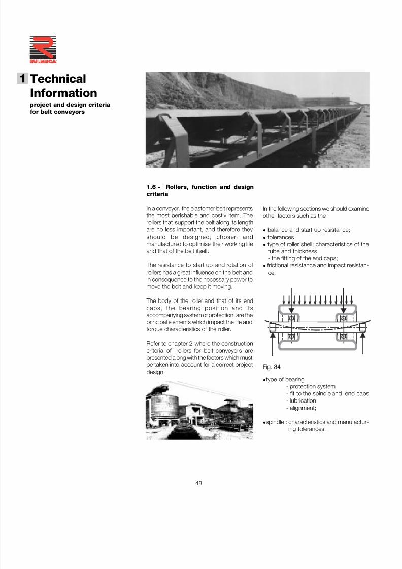
7/27/2019 31801183 Idler Roller
http://slidepdf.com/reader/full/31801183-idler-roller 50/308
48
Technical
Informationproject and design criteriafor belt conveyors
1
®
1.6 - Rollers, function and design
criteria
In a conveyor, the elastomer belt representsthe most perishable and costly item. Therollers that support the belt along its lengthare no less important, and therefore theyshould be designed, chosen andmanufactured to optimise their working lifeand that of the belt itself.
The resistance to start up and rotation of rollers has a great influence on the belt andin consequence to the necessary power tomove the belt and keep it moving.
The body of the roller and that of its endcaps, the bearing position and itsaccompanying system of protection, are theprincipal elements which impact the life andtorque characteristics of the roller.
Refer to chapter 2 where the constructioncriteria of rollers for belt conveyors arepresented along with the factors which mustbe taken into account for a correct projectdesign.
In the following sections we should examineother factors such as the :
• balance and start up resistance;• tolerances ;• type of roller shell; characteristics of the
tube and thickness- the fitting of the end caps;
• frictional resistance and impact resistan-ce;
• type of bearing- protection system- fit to the spindle and end caps- lubrication- alignment;
• spindle : characteristics and manufactur-ing tolerances.
Fig. 34
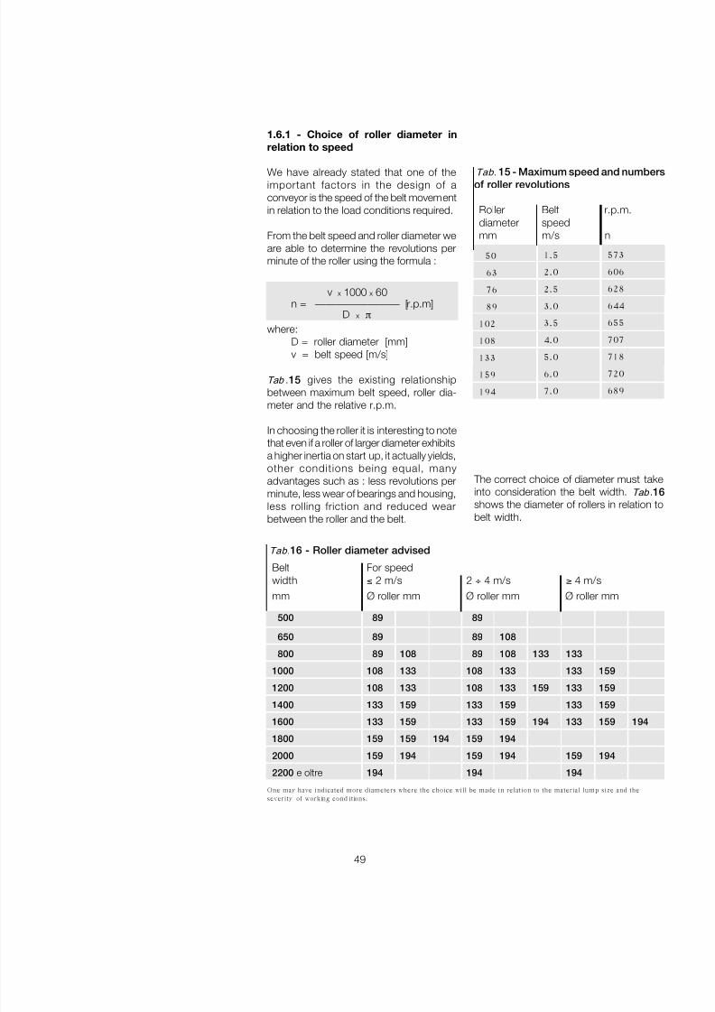
7/27/2019 31801183 Idler Roller
http://slidepdf.com/reader/full/31801183-idler-roller 51/308
49
1.6.1 - Choice of roller diameter inrelation to speed
We have already stated that one of theimportant factors in the design of aconveyor is the speed of the belt movementin relation to the load conditions required.
From the belt speed and roller diameter weare able to determine the revolutions perminute of the roller using the formula :
v x 1000 x 60n = ———————— [r.p.m]
D x πwhere:
D = roller diameter [mm]v = belt speed [m/s]
Tab .15 gives the existing relationshipbetween maximum belt speed, roller dia-meter and the relative r.p.m.
In choosing the roller it is interesting to notethat even if a roller of larger diameter exhibitsa higher inertia on start up, it actually yields,other conditions being equal, manyadvantages such as : less revolutions perminute, less wear of bearings and housing,less rolling friction and reduced wear
between the roller and the belt.
50
63
76
89
102
108
133
159
194
Tab. 15 - Maximum speed and numbersof roller revolutions
Roller Belt r.p.m.diameter speedmm m/s n
573
606
628
644
655
707
718
720
689
1.5
2.0
2.5
3.0
3.5
4.0
5.0
6.0
7.0
The correct choice of diameter must takeinto consideration the belt width. Tab .1shows the diameter of rollers in relation to
belt width.
One may have indicated more diameters where the choice will be made in relation to the material lump size and theseverity of working cond itions.
Belt For speedwidth ≤ 2 m/s 2 ÷ 4 m/s ≥ 4 m/smm Ø roller mm Ø roller mm Ø roller mm
500 89 89
650 89 89 108
800 89 108 89 108 133 133
1000 108 133 108 133 133 159
1200 108 133 108 133 159 133 159
1400 133 159 133 159 133 159
1600 133 159 133 159 194 133 159 194
1800 159 159 194 159 194
2000 159 194 159 194 159 194
2200 e oltre 194 194 194
Tab. 16 - Roller diameter advised
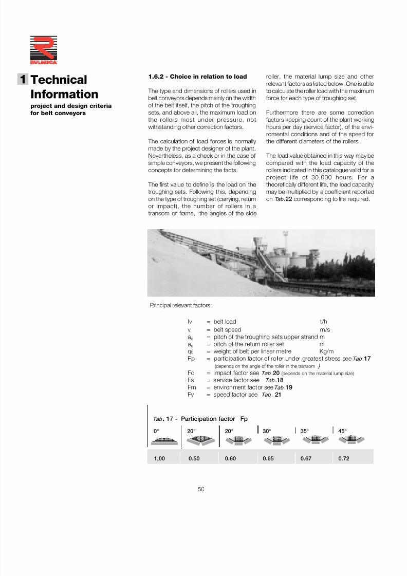
7/27/2019 31801183 Idler Roller
http://slidepdf.com/reader/full/31801183-idler-roller 52/308
50
Technical
Informationproject and design criteriafor belt conveyors
1
®
Principal relevant factors:
Iv = belt load t/hv = belt speed m/sa o = pitch of the troughing sets upper strand ma u = pitch of the return roller set mq b = weight of belt per linear metre Kg/mFp = participation factor of roller under greatest stress see Tab .17
(depends on the angle of the roller in the transom ) Fd = i mpact factor see Tab .20 (depends on the material lump size)
Fs = s ervice factor see Tab .18Fm = environment factor see Tab .19
Fv = speed factor see Tab . 21
1.6.2 - Choice in relation to load
The type and dimensions of rollers used in
belt conveyors depends mainly on the widthof the belt itself, the pitch of the troughingsets, and above all, the maximum load onthe rollers most under pressure, notwithstanding other correction factors.
The calculation of load forces is normallymade by the project designer of the plant.Nevertheless, as a check or in the case of simple conveyors, we present the followingconcepts for determining the facts.
The first value to define is the load on thetroughing sets. Following this, dependingon the type of troughing set (carrying, returnor impact), the number of rollers in atransom or frame, the angles of the side
roller, the material lump size and otherrelevant factors as listed below. One is ableto calculate the roller load with the maximum
force for each type of troughing set.
Furthermore there are some correctionfactors keeping count of the plant workinghours per day (service factor), of the envi-romental conditions and of the speed forthe different diameters of the rollers.
The load value obtained in this way may becompared with the load capacity of therollers indicated in this catalogue valid for aproject life of 30.000 hours. For atheoretically different life, the load capacitymay be multiplied by a coefficient reportedon Tab .22 corresponding to life required.
Tab . 17 - Participation factor Fp
0° 20 ° 20 ° 30 ° 35 ° 45 °
1,00 0.50 0.60 0.65 0.67 0.72
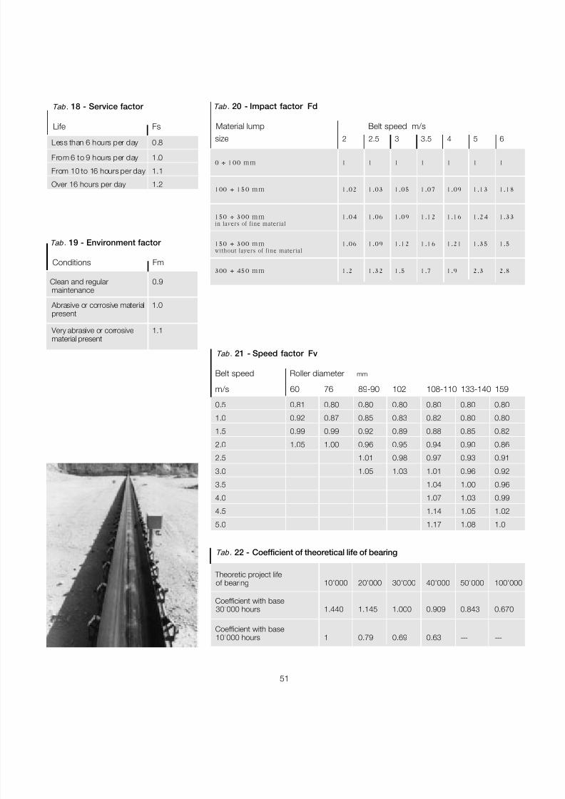
7/27/2019 31801183 Idler Roller
http://slidepdf.com/reader/full/31801183-idler-roller 53/308
51
Tab . 21 - Speed factor Fv
Belt speed Roller diameter mm
m/s 60 76 89-90 102 108-110 133-140 159
0.5 0.81 0.80 0.80 0.80 0.80 0.80 0.80
1.0 0.92 0.87 0.85 0.83 0.82 0.80 0.80
1.5 0.99 0.99 0.92 0.89 0.88 0.85 0.82
2.0 1.05 1.00 0.96 0.95 0.94 0.90 0.86
2.5 1.01 0.98 0.97 0.93 0.91
3.0 1.05 1.03 1.01 0.96 0.92
3.5 1.04 1.00 0.96
4.0 1.07 1.03 0.99
4.5 1.14 1.05 1.02
5.0 1.17 1.08 1.0
Tab . 22 - Coefficient of theoretical life of bearing
Theoretic project lifeof bearing 10'000 20'000 30'000 40'000 50'000 100'000
Coefficient with base30'000 hours 1.440 1.145 1.000 0.909 0.843 0.670
Coefficient with base10'000 hours 1 0.79 0.69 0.63 --- ---
Tab . 20 - Impact factor Fd
Material lump Belt speed m/s
size 2 2.5 3 3.5 4 5 6
0 ÷ 100 mm 1 1 1 1 1 1 1
100 ÷ 150 mm 1.02 1.03 1.05 1.07 1.09 1.13 1.18
150 ÷ 300 mm 1.04 1.06 1.09 1.12 1.16 1.24 1.33in layers of fine material
150 ÷ 300 mm 1.06 1.09 1.12 1.16 1.21 1.35 1.5without layers of fine material
300 ÷ 450 mm 1.2 1.32 1.5 1.7 1.9 2.3 2.8
Tab . 18 - Service factor
Life Fs
Less than 6 hours per day 0.8
From 6 to 9 hours per day 1.0
From 10 to 16 hours per day 1.1
Over 16 hours per day 1.2
Tab . 19 - Environment factor
Conditions Fm
Clean and regular 0.9maintenance
Abrasive or corrosive material 1.0present
Very abrasive or corrosive 1.1material present
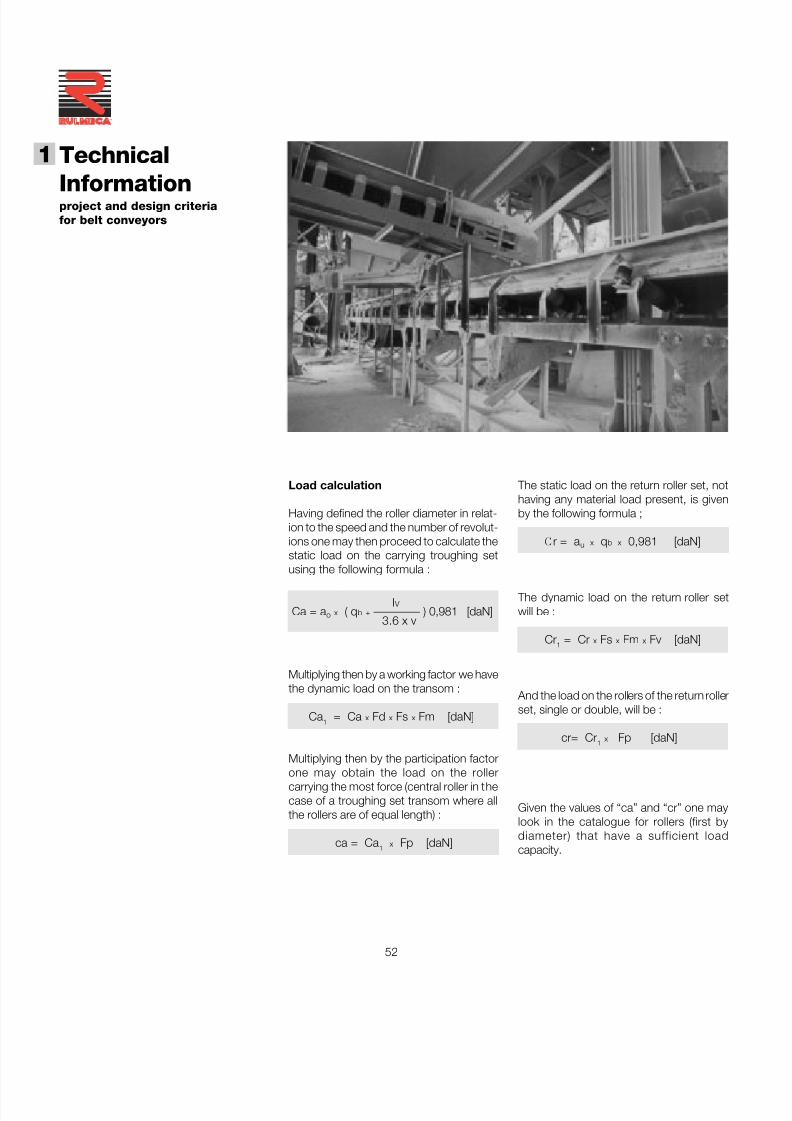
7/27/2019 31801183 Idler Roller
http://slidepdf.com/reader/full/31801183-idler-roller 54/308
52
Technical
Informationproject and design criteriafor belt conveyors
1
®
The static load on the return roller set, nothaving any material load present, is givenby the following formula ;
C r = a u x q b x 0,981 [daN]
The dynamic load on the return roller setwill be :
Cr 1 = Cr x Fs x Fm x Fv [daN]
And the load on the rollers of the return rollerset, single or double, will be :
cr= Cr 1 x Fp [daN]
Given the values of “ca” and “cr” one maylook in the catalogue for rollers (first bydiameter) that have a sufficient loadcapacity.
Load calculation
Having defined the roller diameter in relat-ion to the speed and the number of revolut-ions one may then proceed to calculate thestatic load on the carrying troughing setusing the following formula :
I V Ca = a o x ( q b + ———— ) 0,981 [daN]
3.6 x v
Multiplying then by a working factor we havethe dynamic load on the transom :
Ca 1 = Ca x Fd x Fs x Fm [daN]
Multiplying then by the participation factorone may obtain the load on the rollercarrying the most force (central roller in thecase of a troughing set transom where allthe rollers are of equal length) :
ca = Ca 1 x Fp [daN]

7/27/2019 31801183 Idler Roller
http://slidepdf.com/reader/full/31801183-idler-roller 55/308
53
1.7 - Loading of belt and impact rollers
The feed sys tem of mat erial fal ling ordropping onto a belt conveyor must beconstructed to minimise or eliminate impactdamage to the belt material and surface.
This is of particular importance when thematerial falls from a considerable height andconsists of large lumps with sharp edges.
The rollers supporting or carrying the beltin the loading zone are normally installedas impact design (with rubber rings),mounted onto troughing set frames setclose to each other. In this way the belt issupported in a flexible manner.
It is a widely held view that the use of suspension sets of the “garland” design-Fig.37-38, thanks to their intrinsic flexiblecharacteristics absorb with great efficiencythe impact of materials falling onto the beltand, what is more, the “garland” is able toadapt to conform to the shape of thecharge (or load).
Fig.35
Fig.36
Fig.37
Fig.38
7/27/2019 31801183 Idler Roller
http://slidepdf.com/reader/full/31801183-idler-roller 56/308
54
Technical
Informationproject and design criteriafor belt conveyors
1
®
Please refer to chapter 3 of this cataloguefor greater detail regarding the programmeof the design of impact rollers with rubber
rings of high shock absorbing qualities andfor the programme of suspension sets as“garland” design.
1.7.1 - Calculation of associated for-ces on impact rollers
The definition of the correct load fall heightHc may be given by the folowing formula :
Hc = Hf + Hv x sen 2 γ
where: Hf = fall height from the upper face of
the loading belt to the contactpoint of material contained in thehopper ;
Hv = height from the contact point of material contained in the hopperto the belt face of the lower belt ;
γ = hopper inclination angle.
In the choice of impact rollers we proposeto follow two significant design aspects :
- constant loading with uniform fine material
- loading with material consisting of largelumps.
Particular attention must be paid at theproject stage to the feed system and to thedesign of impact troughing sets.
The project designer of the conveyor systemmust take into account that :
- the impact of material onto the belt musttake place in the conveyor direction and ata speed that approximates to the speed of the belt.
- the loading hopper is positioned so thatmaterial falling from it is deposited as nearas possible to the centre of the belt.
Fig.39
- the height that the material falls must bereduced to the minimum possible,compatible with the requirements of theplant design.
γ
H v
H f
NO
Fig.40
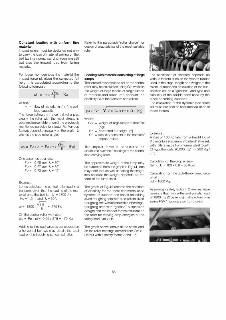
7/27/2019 31801183 Idler Roller
http://slidepdf.com/reader/full/31801183-idler-roller 57/308
55
Constant loading with uniform finematerial.Impact rollers must be designed not only
to carry the load of material arriving on thebelt (as in a normal carrying troughing set)but also the impact load from fallingmaterial.
For loose, homogenous fine material theimpact force pi, given the corrected fallheight, is calculated according to thefollowing formula :
√ Hc pi ≅ I V x ––––– [Kg] 8
where: I V = flow of material in t/hr (the belt
load capacity The force acting on the central roller pic,clearly the roller with the most stress, isobtained on consideration of the previouslymentioned participation factor Fp. Variousfactors depend principally on the angle λwich is the side roller angle:
√ Hc pic ≅ Fp x pi = Fp x I V x ––––– [Kg]8
One assumes as a rule:Fp = 0.65 per λ = 30 °Fp = 0.67 per λ = 35 °Fp = 0.72 per λ = 45 °
Example:Let us calculate the central roller load in atransom, given that the loading of the ma-terial onto the belt is: Iv = 1800 t/h,Hc = 1.5m and λ = 30 °:
√ 1.5pi = 1800 x ––––– = 275 Kg 8
On the central roller we have:
pic = Fp x pi = 0.65 x 275 = 179 Kg
Adding to this load value as considered ona horizontal belt we may obtain the totalload on the troughing set central roller.
Example : A load of 100 Kg falls from a height Hc of 0.8 m onto a suspension “garland” style set,with rollers made from normal steel (coeff,Cf hypothetically 20,000 Kg/m = 200 Kg / cm).
Calculation of the drop energy :
Gm x Hc = 100 x 0.8 = 80 Kgm
Calculating from the table the dynamic forceof fall :pd = 1800 Kg.
Assuming a safety factor of 2 we must havebearings that may withstand a static loadof 1800 Kg; (2 bearings) that is rollers fromseries PSV7 (bearings 6308; Co = 2400 Kg) .
Loading with material consisting of largelumps.
The force of dynamic load pd on the centralroller may be calculated using G m which isthe weight of large blocks of single lumpsof material and takes into account theelasticity Cf of the transom and rollers.
p d ≅ Gm + √ ( 2 x G m x Hc x Cf ) [Kg]
where: Gm = weight of large lumps of material
[Kg]Hc = corrected fall height [m]Cf = elasticity constant of the transom/
impact rollers.
Th e im pa ct fo rce is co ns id ered asdistributed over the 2 bearings of the centralload carrying roller.
The approximate weight of the lump maybe extracted from the graph in Fig. 41 : onemay note that as well as taking the lengthinto account the weight depends on theform of the lump itself.
The graph of Fig. 42 records the constantof elasticity for the most commonly usedsystems of support and shock absorbing(fixed troughing sets with steel rollers, fixedtroughing sets with rollers with rubber rings,troughing sets with “garland” suspensiondesign) and the impact forces resultant onthe roller for varying drop energies of the
falling load Gm x Hc.
The graph shows above all the static loadon the roller bearings derived from Gm xHc but with a safety factor 2 and 1.5.
Refer to the paragraph “roller choice” fordesign characteristics of the most suitableroller.
The coefficient of elasticity depends onvarious factors such as the type of rubberused in the rings, length and weight of therolers, number and articulation of the sus-pension set as a "garland", and type andelasticity of the flexible parts used by thestock absorbing supports.
The calculation of the dynamic load forcepd must fore cast an accurate valuation of these factors.
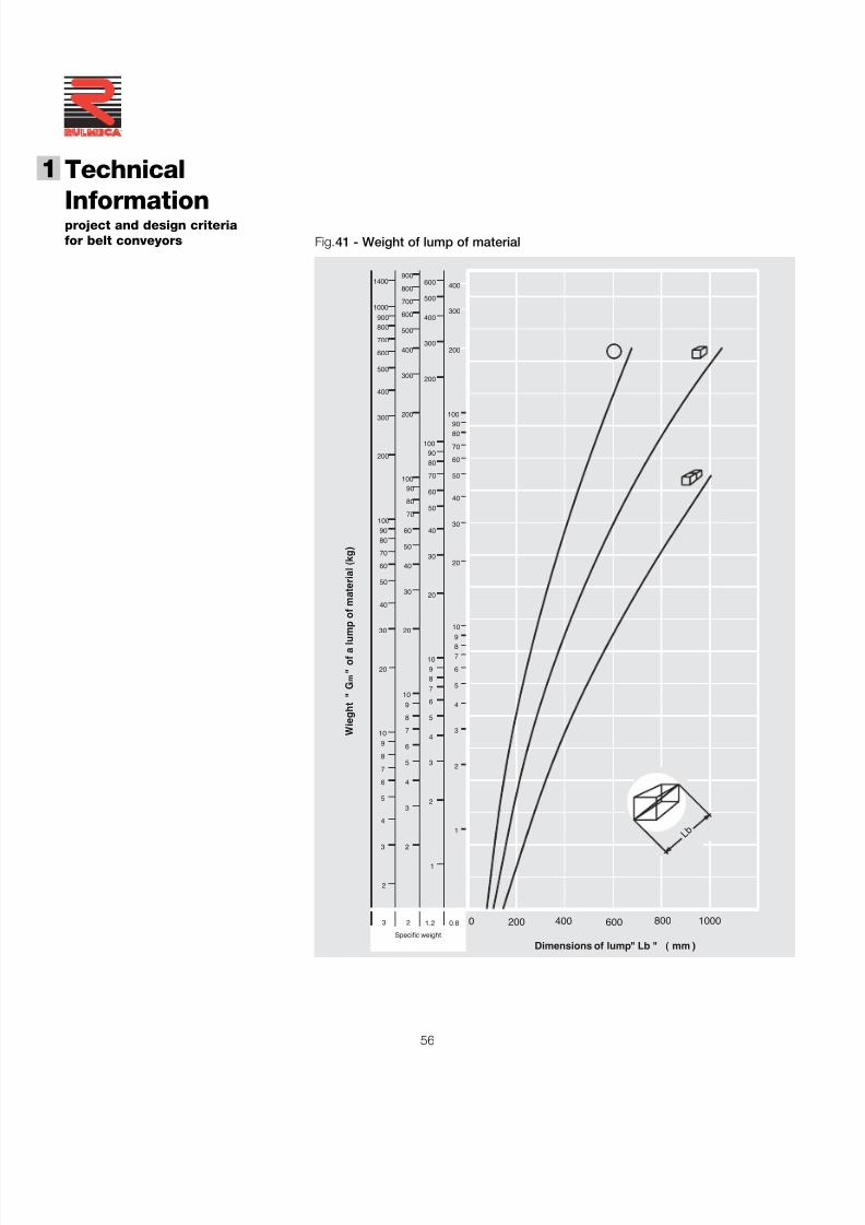
7/27/2019 31801183 Idler Roller
http://slidepdf.com/reader/full/31801183-idler-roller 58/308
56
Technical
Informationproject and design criteriafor belt conveyors
1
®
6090 4030
80
90100
200
5070
60
70
8090
100
4050
60
70100
500
600
800900
1400
1000
400
700
800
900
400
500
600
300
200
300
400
300
400
500
600
700 300
200
200
100
8090
Specific weight
1.223
2
2
3
4
5
3
2
1
6
7
8
9
910 4
5
6
4
5
6
7
83
20
20
30
89
10
869
710
1057
30
40
50
50
60
70
80
20
2030
40
0.8
1
3
4
2
600 800 10000
W i e g h t " G m
" o f a l u m p o f m a t e r i a l ( k g )
400200
Dimensions of lump" Lb " ( mm )
L b
Fig.41 - Weight of lump of material
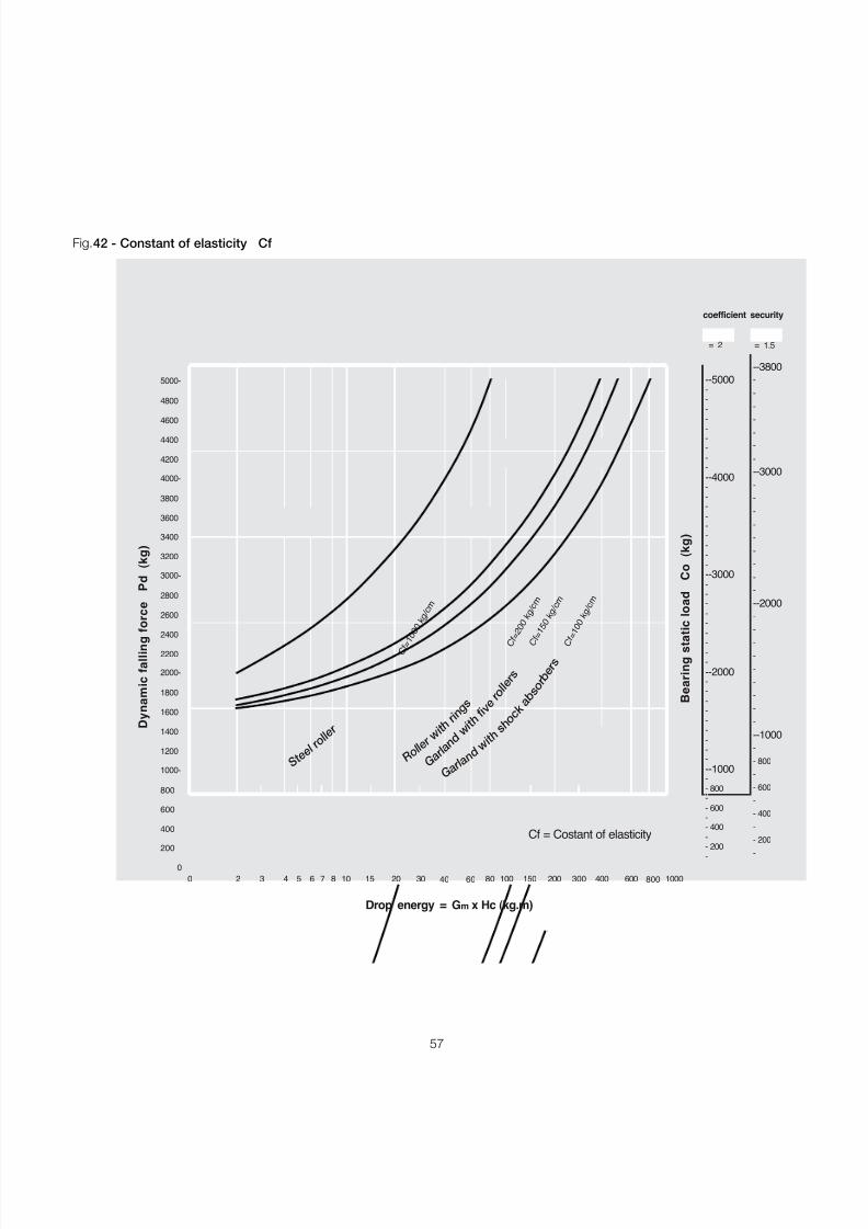
7/27/2019 31801183 Idler Roller
http://slidepdf.com/reader/full/31801183-idler-roller 59/308
57
Fig.42 - Constant of elasticity Cf
5000-
4200
4400
4600
4800
200
400
600
800
1200
1400
1600
1800
2200
2400
2600
2800
3200
3400
3600
3800
1000-
2000-
3000-
4000-
coefficient security
00
2 84 6 10 20 40060 8040 100 2003 5 7 15 30 150
= 1.5= 2
300 800600 1000
-
-
-
--
-
-
-
-
-
-
-
--
-
--
-
-
-
--
-
-
- 200
- 800
- 400
- 600
- 200
- 400
- 600
- 800
-
--1000
--1000-
-
-
-
-
-
-
-
-
-
-
-
-
-
-
-
-
-
-
-
-
-
-
-
-
-
--2000
--3000
--4000
--5000
--3000
--3800
--2000
-
-
-
-
-
-
-
-
-
-
-
-
-
-
-
-
-
-
-
-
Drop energy = G m x Hc (kg.m)
B e a r i n g s
t a t i c l o a
d
C o
( k g
)
D y n a m
i c f a l l i n g
f o r c e
P d ( k g
)
C f = 1 0 0 0 k g / c m
Cf = Costant of elasticity
C f = 1 0 0
k g / c m
C f = 1 5 0
k g / c m
C f = 2 0 0
k g / c m
S t e e l
r o l l e r
R o l l e
rw i t hr i n
g s
G a r l a n
dw i t h
f i v er o l l e
r s
G a r l a n
d w i t h
s h o c
ka b
s o r b
e r s
7/27/2019 31801183 Idler Roller
http://slidepdf.com/reader/full/31801183-idler-roller 60/308
58
Technical
Informationproject and design criteriafor belt conveyors
1
®
1.8 - Other accessories
Amongst all of other conveyor components,
the belt cleaning system and covers areregarded in certain situations, of fund-amental importance and must be consider -ed at an early stage in the project design of the conveyor itself.
1.8.1 - Belt cleaners
Savings in utilising efficient systems of beltcleaning may be amply demonstrated, inparticular resulting from a reduction in beltmaintenance time and increased product-ion, proportional to the quantity of materialrecovered in the process and a largeincrease in the life of moving parts.
The static systems that are utilised themost are the most diverse as they may beapplied along all positions on the dirty sideof the belt. They are acting directly on thebelt using a segmented blade. Fig. 44
Fig.43 - Ideal positions for the installation of cleaning devices
43
1 2
3 on internal side of belt on the return section and beforethe snub pulleys o r directiona l chang e pulley.
4 on internal side o f belt before the return pulley.
1 on drive pulley
2 at a bout 200mm after the tange ntial point where beltleaves pulley
Fig.44
There are a variety of devices used for belt
cleaning. The majority of these may bedivided into two groups : static anddynamic.
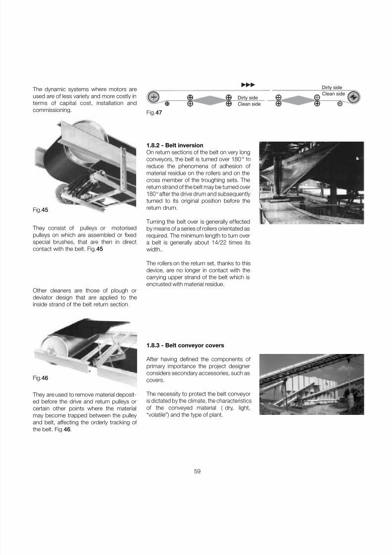
7/27/2019 31801183 Idler Roller
http://slidepdf.com/reader/full/31801183-idler-roller 61/308
59
1.8.2 - Belt inversionOn return sections of the belt on very longconveyors, the belt is turned over 180 ° toreduce the phenomena of adhesion of material residue on the rollers and on thecross member of the troughing sets. Thereturn strand of the belt may be turned over180 ° after the drive drum and subsequentlyturned to its original position before thereturn drum.
Turning the belt over is generally effectedby means of a series of rollers orientated asrequired. The minimum length to turn overa belt is generally about 14/22 times itswidth..
The rollers on the return set, thanks to thisdevice, are no longer in contact with thecarrying upper strand of the belt which is
encrusted with material residue.
1.8.3 - Belt conveyor covers
After having defined the components of primary importance the project designerconsiders secondary accessories, such as
covers.
The necessity to protect the belt conveyoris dictated by the climate, the characteristicsof the conveyed material ( dry, light,“volatile”) and the type of plant.
Fig.45
Fig.46
The dynamic systems where motors areused are of less variety and more costly interms of capital cost, installation andcommissioning.
They consist of pulleys or motorisedpulleys on which are assembled or fixedspecial brushes, that are then in directcontact with the belt. Fig. 45
Other cleaners are those of plough ordeviator design that are applied to theinside strand of the belt return section.
They are used to remove material deposit-ed before the drive and return pulleys orcertain other points where the materialmay become trapped between the pulleyand belt, affecting the orderly tracking of the belt. Fig. 46 .
Dirty sideClean side
Dirty side
Clean side
Fig.47
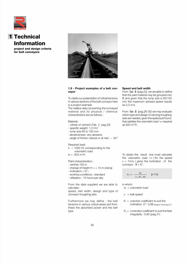
7/27/2019 31801183 Idler Roller
http://slidepdf.com/reader/full/31801183-idler-roller 62/308
60
Technical
Informationproject and design criteriafor belt conveyors
1
®
To obtain the result one must calculatethe volumetric load I VT ( for the speedv = 1m/s ) given the inclination of theconveyor δ = 6 °.
IMI VT = ————— [m 3 /h]
v x K x K 1
in which:IM = volumetric load
v = belt speed
K = crrection coefficient to suit theinclination 6 °: 0,98 (diagram Fig 8 pag.31).
K 1 = correction coefficient to suit the feedirregularity : 0,90 (pag.31)
Speed and belt widthFrom Tab . 3 (pag.23) we are able to definethat the said material may be grouped intoB and given that the lump size is 80/150mm the maximum advised speed resultsas 2,3 m/s.
From Tab . 5 (pag.26-30) we may evaluatewhich type and design of carrying troughingsets are needed, given the speed just found,that satisfies the volumetric load I M requiredas 833 m 3 /h.
1.9 - Project examples of a belt con-veyor
To clarify our presentation of critical tensionsin various sections of the belt conveyor hereis a project example.
The relative data concerning the conveyedmaterial and its physical / chemicalcharacteristics are as follows :
Material:- clinker of cement (Tab. 2 pag.20)- specific weight: 1.2 t/m 3
- lump size 80 to 150 mm- abrasiveness: very abrasive- angle of friction natural or at rest : ~ 30 °
Required load:I V = 1000 t/h corresponding to the
volumetric loadIM = 833 m 3 /h
Plant characteristics :- centres 150 m- change of height H = + 15 m (rising)- inclination = 6 °~- working conditions : standard- utilisation : 12 hours per day
From the data supplied we are able tocalculate :speed, belt width, design and type of conveyor troughing sets.
Furthermore we may define : the belttensions in various critical areas and fromthese the absorbed power and the belttype.
7/27/2019 31801183 Idler Roller
http://slidepdf.com/reader/full/31801183-idler-roller 63/308
61
- for the return rollers the static load will be:
Cr = a u x q b x 0,981 [daN]
Cr= 3 x 9,9 x 0,981 = 29,2
the dynamic load will be:
Cr1 = Cr x Fs x Fm x Fv [daN]
Cr1= 29,2 x 1,1 x 1 x 0,97 = 31,2
where:Fv = 0,97 speed factor (it has been considered
that relative to 2,5 m/s see Tab . 21, pag.51)
choosing the return troughing set with plainroller the load on the return roller will be :
cr = Cr1 x Fp [daN]
cr= 31,2 x 1 = 31,2
where from Tab . 17 the participation factorwith return plain roller set Fp = 1
We are able therefore to choose a belt1000 mm, the rollers for carring and returnidlers both of loaded and return belt (seeChapter 2)
- rollers for carrying idlers type PSV/1, ø
108 mm, with bearings 6204 of lengthC = 388 mm with load capacity 148 Kgthat satisfies the required loading of 113,2 Kg ,
- return roller type PSV/1, ø108 mm , withbearings 6204, length C=1158 mm withload capacity 101 Kg that satisfies therequired loading of 31,2 Kg.
the load on the central roller of a carryingtroughing set is given by :
ca = Ca 1 x Fp [daN]
ca = 174,2 x 0,65 = 113,2
where from Tab . 17 pag.50 the particip-ation factor of a troughing set 30 ° Fp = 0,65
Roller choiceIn Tab . 16 pag.49 with a belt of 1000 mmand a speed of 2.3 m/s we may chooserollers with diameter 108 mm.
We may now proceed to determine the loadfalling on the roller in the carrying strand andthose of the return strand.
Assuming we may use a be lt wi th aresistance class equal to 315 N/mm, withcover thickness 4+2, and with a value q b
of 9,9 kg/m, we have:
- for carrying rollers the static load will be:
I V Ca = a o x ( q b + ———— ) x 0,981 [daN] 3,6 x v
1000Ca =1,2( 9,9+ ———— ) 0,981 = 153,8
3,6 x 2,3
the dynamic load will be:
Ca 1 = Ca x Fd x Fs x Fm [daN]
Ca 1 = 153,8 x 1,03 x 1,1 x 1 = 174,2
where:Fd = 1,03 from table 20 , pag.51
Fs = 1,10 from table18 , pag.51
Fm = 1 from table 19 , pag.51
Troughing set pitch The pitch may be chosen as a function of the deflection of the belt between two con-secutive troughing sets.
Tab . 6 pag.34 shows how to determinethe maximum pitch of troughing sets, as afunction of the belt width and the specificweight of the conveyed material.
We need to verify that the deflection doesnot supersede 2% of the pitch.
A greater deflection may give rise to materialmass deformation during the beltmovement, and consequently elevatedfriction.
Then we would be able to determine a majorfactor: that is major power absorption,giving rise to unusual stresses whether onthe rollers or in the belt over and above thepremature wear in the cover of the belt.
In our example, given that the belt width is1000 mm with specific weight of materialof 1.2 t/m 3 the tables indicate that :
- for the carrying troughing sets the advisedpitch is that of 1.2 m
- for the return sets the advised pitch is thatof 3.0 m.
Substituting we have: 833
I VT = ————————— = 410 m 3 /h
2,3 x 0,98 x 0,90
Given the angle of repose of the material inquestion is about 30 ° from Tab . 1 pag.19we may deduce that the angle of surchargewould be established in the order of 20 °.
Having chosen a carrying troughing set witha transom side roller angle of λ = 30 °, thebelt width that meets the load requirementI VT of 410 m 3 /h at 1 m/s is 1000 mm.
7/27/2019 31801183 Idler Roller
http://slidepdf.com/reader/full/31801183-idler-roller 64/308
62
Technical
Informationproject and design criteriafor belt conveyors
1
®
Tangential force and absorbed powerWe may now determine the total tangential force Fu at the drum periphery extractingthe values q RO , q RU and q G.
given:D = 108 roller diameterf = 0,017 friction coefficient inside material and of the rotating parts ( Tab . 9 pag.38)
Cq = 1,5 fixed coefficient of resistance ( Tab . 7 pag.38)q b = 9,9 Kg/m ( utilising a belt resistance class 315 N/mm with a cover thickness 4+2 Tab . 10 pag.39 )
Ct = 1 coefficient of passive resistance given by the temperature (per q RO - q RU vedi Tab .11 pag.39 )
weight of rotating parts
upper troughing set 17,8
q RO = ————————————— = ——— = 14,8 Kg/mpitch of upper sets 1,2
weight of rotating parts
lower troughing set 13,3q RU = ————————————— = ——— = 4,4 Kg/m pitch of upper sets 3,0
I V
1000q G = ———— = ————— = 120,8 Kg/m 3,6 x v 3,6 x 2,3
The total tangential force Fu is given by the algebraic sum of the tangential forces Fa andFr relative to upper and lower sections of belt for which:
Fu = Fa + Fr [daN]
Fa = [ L x Cq x f x Ct ( q b + q G + q RO ) + H x ( qG + q b ) ] x 0,981 [daN]Fa = [150 x1,5 x 0,017 x 1 (9,9+120,8+14,8)+15 x (120,8+9,9)] x 0,981 = 2469
Fr = [ L x Cq x f x Ct ( q b + q RU ) - ( H x q b ) ] x 0,981 [daN]Fr = [150 x 1,5 x 0,025 x 1 (9,9 + 4,4) - (15 x 9,9)] x 0,981 = - 92
Fu = Fa + Fr = 2469 + ( - 92 ) = 2377 .
We consider an efficiency of the reduction gear and of possible transmissions as η = 0,86will be :
Fu x v 2377 x 2,3P = ———— [ kW ] = ——————— ≅ 64 kW
100 x η 100 x 0,86
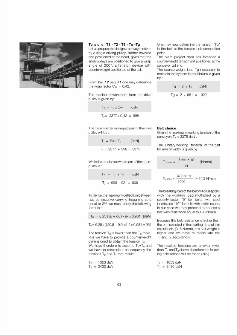
7/27/2019 31801183 Idler Roller
http://slidepdf.com/reader/full/31801183-idler-roller 65/308
63
Tensions T1 - T2 - T3 - To -TgLet us propose to design a conveyor drivenby a single driving pulley, rubber covered
and positioned at the head, given that thesnub pulleys are positioned to give a wrapangle of 200 ° ; a tension device withcounterweight positioned at the tail.
From Tab. 12 pag. 41 one may determinethe wrap factor Cw = 0,42.
The tension downstream from the drivepulley is given by :
T 2 = Fu x Cw [daN]
T 2 = 2377 x 0,42 = 998
The maximum tension upstream of the drivepulley will be :
T 1 = Fu + T 2 [daN]
T 1 = 2377 + 998 = 3375
While the tension downstream of the returnpulley is :
T 3 = T 2 + Fr [daN]
T 3 = 998 - 92 = 906
To derive the maximum deflection betweentwo consecutive carrying troughing setsequal to 2% we must apply the followingformula :
T 0 = 6,25 ( q b + q G ) x a 0 x 0,981 [daN]
T 0 = 6.25 x (120,8 + 9,9) x1,2 x 0,981 = 961
The tension T 3 is lower than the T 0 there-fore we have to provide a counterweightdimensioned to obtain the tension T 0.We have therefore to assume T 3=T 0 andwe have to recalculate consequently thetensions T 2 and T 1 that result:
T 2 = 1053 daN T 3 = 3430 daN
One may now determine the tension “Tg”in the belt at the tension unit connectionpoint.
The plant project data has foreseen acounterweight tension unit positioned at theconveyor tail end.
The counterweight load Tg necessary tomaintain the system in equilibrium is givenby :
Tg = 2 x T 3 [daN]
Tg = 2 x 961 = 1922
Belt choiceGiven the maximum working tension of theconveyor: T 1 = 3375 daN .
The unitary working tension of the beltfor mm of width is given by:
T max x 10Tu max = ———––—–– [N/mm]N
3430 x 10Tu max = ————— = 34,3 N/mm
1000
The breaking load of the belt will correspondwith the working load multiplied by asecurity factor “8” for belts with steelinserts and “10” for belts with textile inserts.In our case we may proceed to choose abelt with resistance equal to 400 N/mm.
Because this belt resistance is higher thanthe one selected in the starting data of this
calculation, (315 N/mm), the belt weight ishigher and we have to recalculate the T 1 and T 2 accordingly.
The resulted tensions are anyway lowerthan T 1 and T 2 above, therefore the follow-ing calculations will be made using
T 2 = 1053 daN T 3 = 3430 daN
7/27/2019 31801183 Idler Roller
http://slidepdf.com/reader/full/31801183-idler-roller 66/308
64
Technical
Informationproject and design criteriafor belt conveyors
1
®
Diameter of drive pulley shaftLet us utilise a motor gearbox to drive the conveyor in question.
Drive pulley data:D = 400 mm diameter (as Tab. 13 )
q T = 220 daN weight of pulleyn = 110 rpma g = 0,180 m distance between the supports and pulley flange
Let us determine the resultant Cp of the tensions and the pulley weight (for simplicity letus suppose T and q T perpendicular between them)
Cp = ߛ ( T 1 + T 2 )2 + q T 2 [daN] = ߛ ( 3430 +1053 ) 2 + 220 2 = 4488 daN
The bending moment will be : Cp 4488
Mf = ———— x a g [daNm] = ––––––– x 0,180 = 404 daNm 2 2
The torsional moment will be : P 64
Mt = ——— x 954,9 [daNm] = ––––––– x 954,9 = 555,6 daNm n 110
One may now determine the ideal bendingmoment :
Mif =ߛ
Mf 2+ 0,75 x Mt2 [daNm] =ߛ
404 2+ 0,75 x 555,6 2 = 629 daNm
Consequently we derive the value of the module of resistance W given that σamm 7,82 daN/ mm 2 for heat treated steel C40
Mif x1000 629 x 1000W = —————— [mm 3] = ––––––––––– = 80435 mm 3
σamm 7,82
from which we may find the diameter of the pulley motor shaft :
3 W X 32 3 80435 X 32
d = mm –––———ߛ = –—–––————ߛ ≅ 93 mm π 3,14
The drum shaft diameter on the bearing seats, will be made according the above formula,or the nearer larger diameter available on the bearing.
The shaft diameter inside the hub and/or inside the drum (normally the raw shaft diameter)is determined with the formulas described in the paragraph " Limits of deflection and anglefor motor and idler pulleys " at pag.47 and in this case the raw shaft diameter results120 mm.
7/27/2019 31801183 Idler Roller
http://slidepdf.com/reader/full/31801183-idler-roller 67/308
65
Diameter of return pulley shaft
Non-drive pulley data :D = 315 mm diameter (as Tab. 13 )
qR = 170 daN pulley weighta g = 0,180 m distance between the support and pulley flange
Let us determine the resultant Cpr of the tensions and the pulley weight (for simplicity letus suppose T 3 and q T is perpendicular between them)
Cpr = ߛ ( 2T 3 )2 + q T 2 [daN] = ߛ ( 2 x 961 ) 2 + 170 2 = 1930 daN
The bending moment will be : Cpr 1930
Mf = ———— x a g [daNm] = ––––––– x 0,180 = 174 daNm 2 2
Consequently we derive the value of the module of resistance W given thatσamm 7,82 daN/mm 2 for heat treated steel C40
Mif x1000 174 x 1000W = ————— [mm 3] = ––––––––––—– = 22250 mm 3
σamm 7,82
from which we may find the diameter of pulley motor shaft :
3 W X 32 3 22250 X 32
d = mm –––———ߛ = ––––————ߛ ≅ 61 mm π 3,14
The drum shaft diameter on the bearingseats, will be made according the aboveformula, or the nearer larger diameter avai-lable on the bearing.
The shaft diameter inside the hub and/orinside the drum (normally the raw shaftdiameter) is determined with the formulasdescribed in the paragraph " Limits of deflection and angle for motor and idlerpulleys " at pag.47 and in this case theraw shaft diameter results 95 mm.
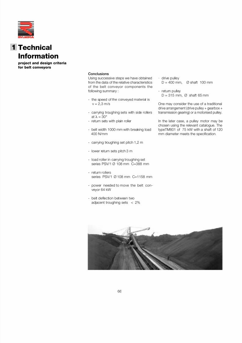
7/27/2019 31801183 Idler Roller
http://slidepdf.com/reader/full/31801183-idler-roller 68/308
66
Technical
Informationproject and design criteriafor belt conveyors
1
®
ConclusionsUsing successive steps we have obtainedfrom the data of the relative characteristicsof the belt conveyor components thefollowing summary :
- the speed of the conveyed material isv = 2,3 m/s
- carrying troughing sets with side rollers
at λ = 30 °- return sets with plain roller
- belt width 1000 mm with breaking load400 N/mm
- carrying troughing set pitch 1,2 m
- lower return sets pitch 3 m
- load roller in carrying troughing setseries PSV/1 Ø 108 mm C=388 mm
- return rollers
series PSV/1 Ø 108 mm C=1158 mm
- power needed to move the belt con-veyor 64 kW
- belt deflection between twoadjacent troughing sets < 2%
- drive pulleyD = 400 mm, Ø shaft 100 mm
- return pulleyD = 315 mm, Ø shaft 65 mm
One may consider the use of a traditionaldrive arrangement (drive pulley + gearbox +transmission gearing) or a motorised pulley.
In the later case, a pulley motor may bechosen using the relevant catalogue. ThetypeTM801 of 75 kW with a shaft of 120mm diameter meets the specification.

7/27/2019 31801183 Idler Roller
http://slidepdf.com/reader/full/31801183-idler-roller 69/308
67
2 Rollers
7/27/2019 31801183 Idler Roller
http://slidepdf.com/reader/full/31801183-idler-roller 70/308
68
®
2 Rollers
Summary 2 Roller s page 67
2.1 Var ious industry uses .............................................. 69
2.2 Rollers, technical design and data ...................... 70
2. 3 Selection method ..................................................... 742.3.1 Choice of diameter in relation to speed ........................ 752.3.2 Choice of type in relation to load .................................. 76
2. 4 Ordering codes ......................................................... 80
2.5 Programme ................................................................ 892.5.1 Rollers series PSV ........................................................ 91
Rollers series PSV non standard ................................... 1202.5.2 Rollers series PL - PLF ................................................. 1212.5.3 Rollers series MPS - M ................................................. 1332.5.4 Rollers series MPR ...................................................... 1492.5.5 Rollers series RTL ........................................................ 1552.5.6 Guide rollers ................................................................ 161
2.6 Rollers with rubber rings ...................................... 1642.6.1 Impact rollers ............................................................... 1662.6.2 Return rollers with spaced rubber rings ......................... 1762.6.3 Return rollers with helical rubber rings .......................... 188
for self cleaning2.6.4 Return rollers with helical steel cage ............................. 192
for self cleaning
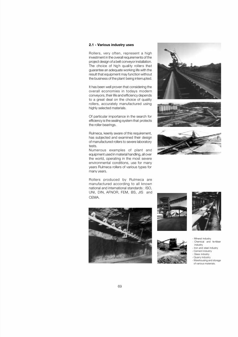
7/27/2019 31801183 Idler Roller
http://slidepdf.com/reader/full/31801183-idler-roller 71/308
69
2.1 - Various industry uses
Rollers, very often, represent a high
investment in the overall requirements of theproject design of a belt conveyor installation.
The cho ice of high quali ty rol lers tha tguarantee an adequate working life with theresult that equipment may function withoutthe business of the plant being interrupted.
It has been well proven that considering theoverall economies in todays modernconveyors, their life and efficiency dependsto a great deal on the choice of qualityrollers, accurately manufactured usinghighly selected materials.
Of particular importance in the search forefficiency is the sealing system that protectsthe roller bearings.
Rulmeca, keenly aware of this requirement,has subjected and examined their designof manufactured rollers to severe laboratorytests.Numerous examples of plant andequipment used in material handling, all overthe world, operating in the most severeenvironmental conditions, use for manyyears Rulmeca rollers of various types formany years.
Rollers produced by Rulmeca aremanufactured according to all knownnational and international standards : ISO,UNI, DIN, AFNOR, FEM, BS, JIS andCEMA.
- Mineral industry- Chemical and fe rtiliser
industry- Iron and steel industry- Cement industry- Glass industry- Quarry industry- Warehousing and storage
of various materials.
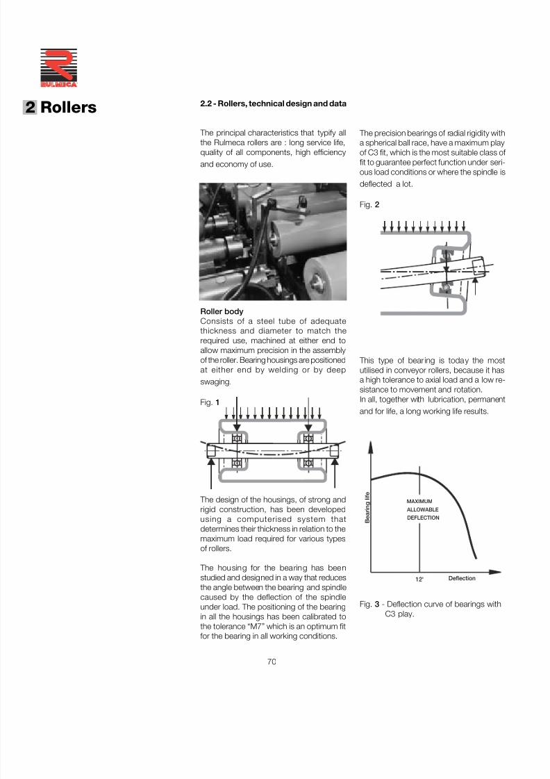
7/27/2019 31801183 Idler Roller
http://slidepdf.com/reader/full/31801183-idler-roller 72/308
70
®
2 Rollers
B e a r i n g
l i f e
Deflection
DEFLECTION
MAXIMUM ALLOWABLE
12'
2.2 - Rollers, technical design and data
The principal characteristics that typify allthe Rulmeca rollers are : long service life,quality of all components, high efficiencyand economy of use.
Roller bodyConsists of a steel tube of adequatethickness and diameter to match therequired use, machined at either end toallow maximum precision in the assemblyof the roller. Bearing housings are positionedat either end by welding or by deepswaging.
Fig. 1
The design of the housings, of strong andrigid construction, has been developedusing a computerised system thatdetermines their thickness in relation to themaximum load required for various typesof rollers.
The housing for the bearing has beenstudied and designed in a way that reducesthe angle between the bearing and spindlecaused by the deflection of the spindleunder load. The positioning of the bearingin all the housings has been calibrated tothe tolerance “M7” which is an optimum fitfor the bearing in all working conditions.
The precision bearings of radial rigidity witha spherical ball race, have a maximum playof C3 fit, which is the most suitable class of fit to guarantee perfect function under seri-ous load conditions or where the spindle isdeflected a lot.
Fig. 2
This type of bearing is today the mostutilised in conveyor rollers, because it hasa high tolerance to axial load and a low re-sistance to movement and rotation.
In all, together with lubrication, permanentand for life, a long working life results.
Fig. 3 - Deflection curve of bearings withC3 play.
7/27/2019 31801183 Idler Roller
http://slidepdf.com/reader/full/31801183-idler-roller 73/308
71
Spindle
The spindle is the load carrying component
of the roller and must be sized in relation tothe load and the roller length.
It is important not to overload the roller dueto the resultant excessive deflection of thespindle which in turn places irregularpressure on the bearing, and reduces, as aconsequence, the roller life.
Fig. 4 - Deflection of spindle under load
Rulmeca rollers are designed to sustain (tothe maximum load conditions as stated inthe relevant tables) a dynamic load,calculated according to the roller type, of 30,000 or 10,000 hours of life (for greaterlife see the relevant tables), with a spindlethat is designed to be underloaded andwhich does not deflect excessively, avoiding
damaging the bearing.
Balance At high conveyor speed, the balance of theroller is of particular importance, especiallywhen we consider the requirements of todays conveyor equipment.
The out of balance force of a roller at lowspeed does not have a great effect, butwhen medium speeds (1,5/2 m/sec) areused, vibrations may be induced which maydamage the bearings and which may sometimes make the roller jump out of its transomsupports.
Sealing and lubrication A quali ty rol ler is charac ter ised by itseffective sealing system.
Scrupulous research and laboratory tests
and above all the practical plant experiencein the most variable environmentalsituations, has enabled Rulmeca to developa particular sealing that guarantees theoptimum bearing performance.
Rulmeca sealing combines the confirmedprotection effectiveness with low resistanceto movement and to rotation, importantfactors that directly influence the conveyorabsorbed power.
All Rulmeca rollers are self-lubricated for life.
Adequate quantities of lithium grease perbearing, with its characteristics of highresistance to ageing, to corrosion and towater, are introduced into the spacesparticularly designed into the sealingsystem.
FF
y = Angle of bearing deflection
FF
y°
bb a
The high quality end machining of the rollerand of the roller body, the numericallycontrolled machine welding, the accuracy
of assembly and the live testing, are allguarantees of the optimum balancing of Rulmeca rollers.
7/27/2019 31801183 Idler Roller
http://slidepdf.com/reader/full/31801183-idler-roller 74/308
72
®
2 Rollers
These machines allow the examination of the following characteristics for each rollertype :
- load capacity and life;
- hermetic sealing of rollers ; stationary andin rotation ;
- hermetic sealing against dust ;
- resistance to rotation and to start up ;
- tests to withstand ambient temperatures-70 ° C a + 200 ° C;
- inspection of the welding by tests usingmagnetoscope and penetrating liquids.
Rulmeca has prepared over many years alaboratory test room, with speciallydesigned machines that permit testing toverify the designs and developments of
rollers for belt conveyors.
In the following photos we may show someof the more important machines andequipment that are situated in the test room.
- Computerised machines for load and lifetesting, in which load cells, digitised bysignals from a personal computer, producea typed report on the behaviour of the roller,and common to all the tests, to differentspeeds and imposed loads.
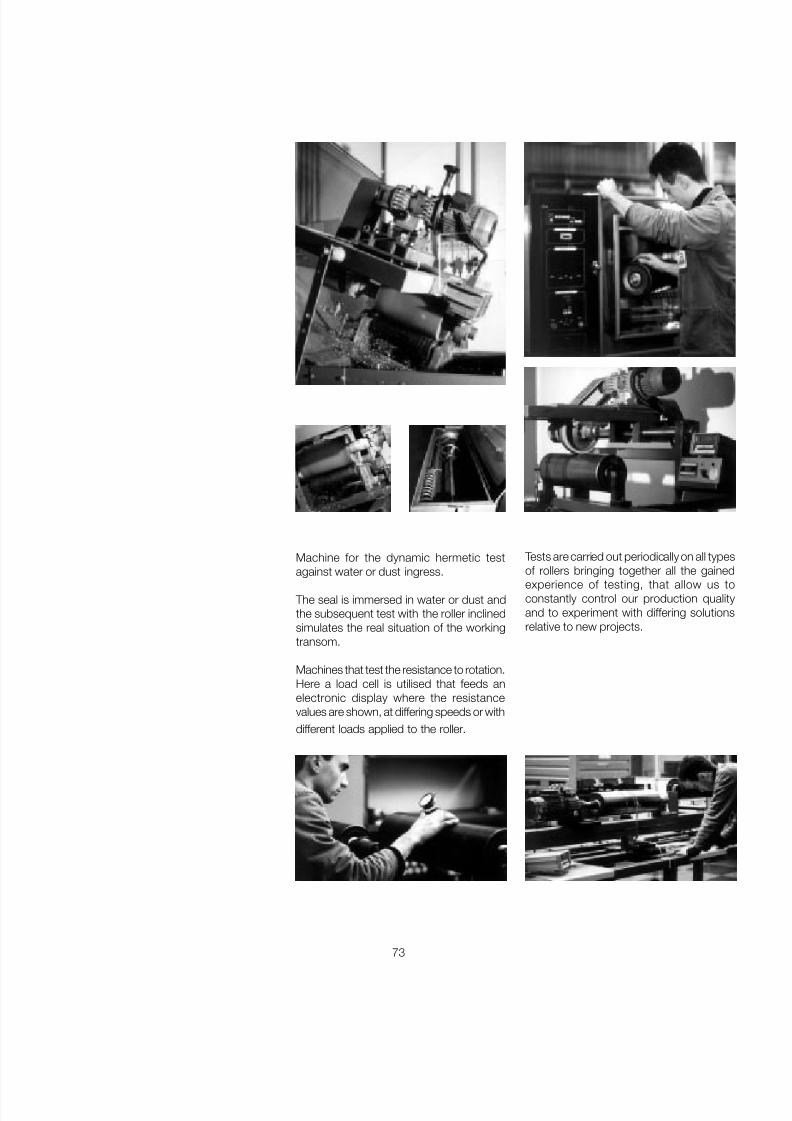
7/27/2019 31801183 Idler Roller
http://slidepdf.com/reader/full/31801183-idler-roller 75/308
73
Machine for the dynamic hermetic testagainst water or dust ingress.
The seal is immersed in water or dust andthe subsequent test with the roller inclinedsimulates the real situation of the workingtransom.
Machines that test the resistance to rotation.Here a load cell is utilised that feeds anelectronic display where the resistancevalues are shown, at differing speeds or withdifferent loads applied to the roller.
Tests are carried out periodically on all typesof rollers bringing together all the gainedexperience of testing, that allow us toconstantly control our production qualityand to experiment with differing solutionsrelative to new projects.
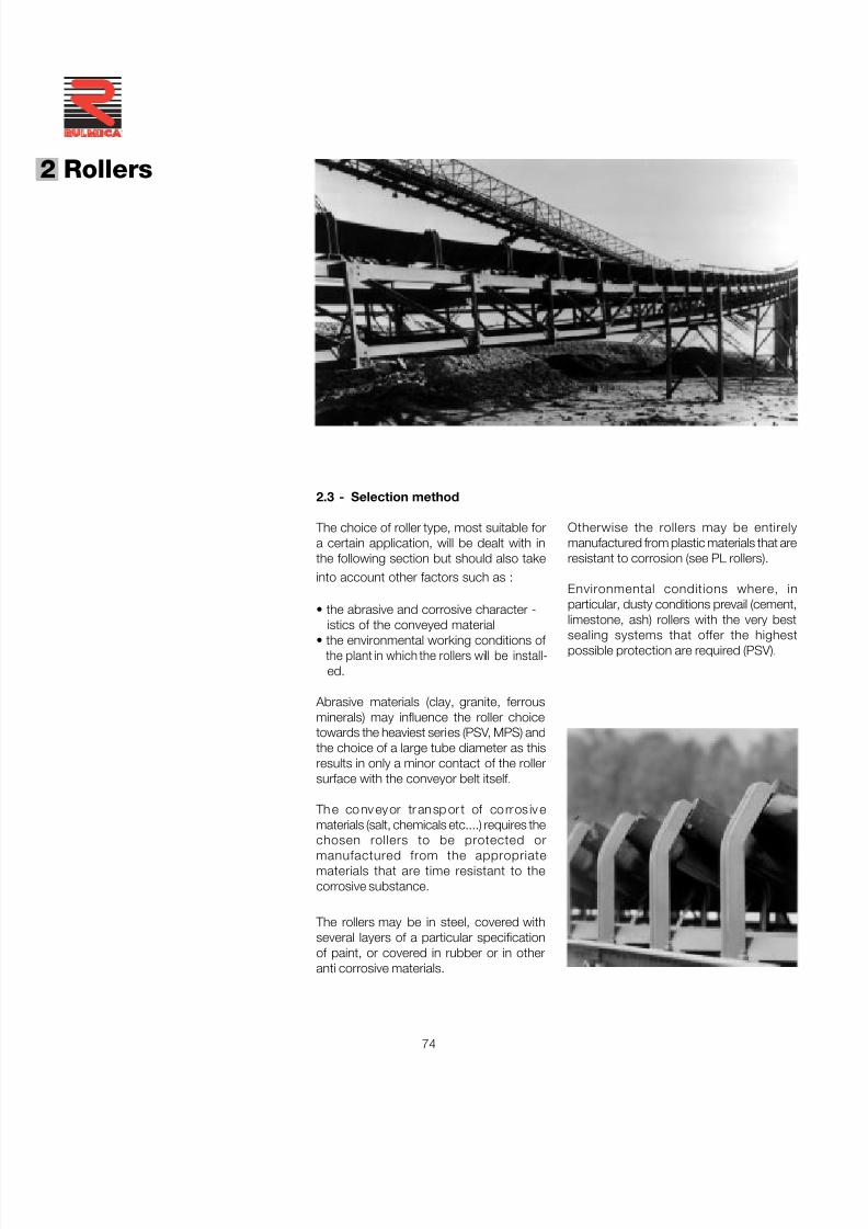
7/27/2019 31801183 Idler Roller
http://slidepdf.com/reader/full/31801183-idler-roller 76/308
74
®
2 Rollers
2.3 - Selection method
The choice of roller type, most suitable fora certain application, will be dealt with inthe following section but should also takeinto account other factors such as :
• the abrasive and corrosive character -istics of the conveyed material
• the environmental working conditions of the plant in which the rollers will be install-
ed.
Abrasive materials (clay, granite, ferrousminerals) may influence the roller choicetowards the heaviest series (PSV, MPS) andthe choice of a large tube diameter as thisresults in only a minor contact of the rollersurface with the conveyor belt itself.
Th e conv eyor tr an sp or t of co rros iv ematerials (salt, chemicals etc....) requires the
chosen rollers to be protected ormanufactured from the appropriatematerials that are time resistant to thecorrosive substance.
The rollers may be in steel, covered withseveral layers of a particular specificationof paint, or covered in rubber or in otheranti corrosive materials.
Otherwise the rollers may be entirelymanufactured from plastic materials that areresistant to corrosion (see PL rollers).
Environmental conditions where, inparticular, dusty conditions prevail (cement,limestone, ash) rollers with the very best
sealing systems that offer the highestpossible protection are required (PSV).
7/27/2019 31801183 Idler Roller
http://slidepdf.com/reader/full/31801183-idler-roller 77/308
75
Where more diameters of roller are indicated the choice will be made in relation to the lump size of material and to the severity of plant conditions.
Belt for speedwidth ≤ 2 m/s 2 ÷ 4 m/s ≥ 4 m/smm Ø roller mm Ø roller mm Ø roller mm
500 89 89
650 89 89 108
800 89 108 89 108 133 133
1000 108 133 108 133 133 159
1200 108 133 108 133 159 133 159
1400 133 159 133 159 133 159
1600 133 159 133 159 194 133 159 194
1800 159 159 194 159 194
2000 159 194 159 194 159 194
2200 e oltre 194 194 194
Tab. 16 - Recommended roller diameter
2.3.1 - Choice of diameter in relation tospeed
It has already been stated that one of theimportant factors to consider in the projectdesign of a conveyor is the speed of thebelt, in relation to the required conditionsof transport.
From the speed of the belt and the rollerdiameter one is able to establish the numberof revolutions of the roller from the formula :
v x 1000 x 60n = ———————— [revs/min]
D x π
where:
D = roller diameter [mm]v = belt speed [m/s]
Tab .15 shows the relationship betweenthe maximum belt speed, the roller diameterand its relative numbers of revolutions.
It is interesting, in the choice of the roller tonote that a roller of large diameter will alsoimply a major start up inertia but may stillbe the choice, because there are manyother advantages to satisfy otherconditions.
50
63
76
89
102
108133
159
194
Tab . 15 - Maximum speed and roller revolutions
Roller Belt rpmdiameter speedmm m/s n
573
606
628
644
655
707718
720
689
1.5
2.0
2.5
3.0
3.5
4.05.0
6.0
7.0
The correct choice of diameter must takeinto account the belt width. Tab .16 indicates our advice for roller diameters.
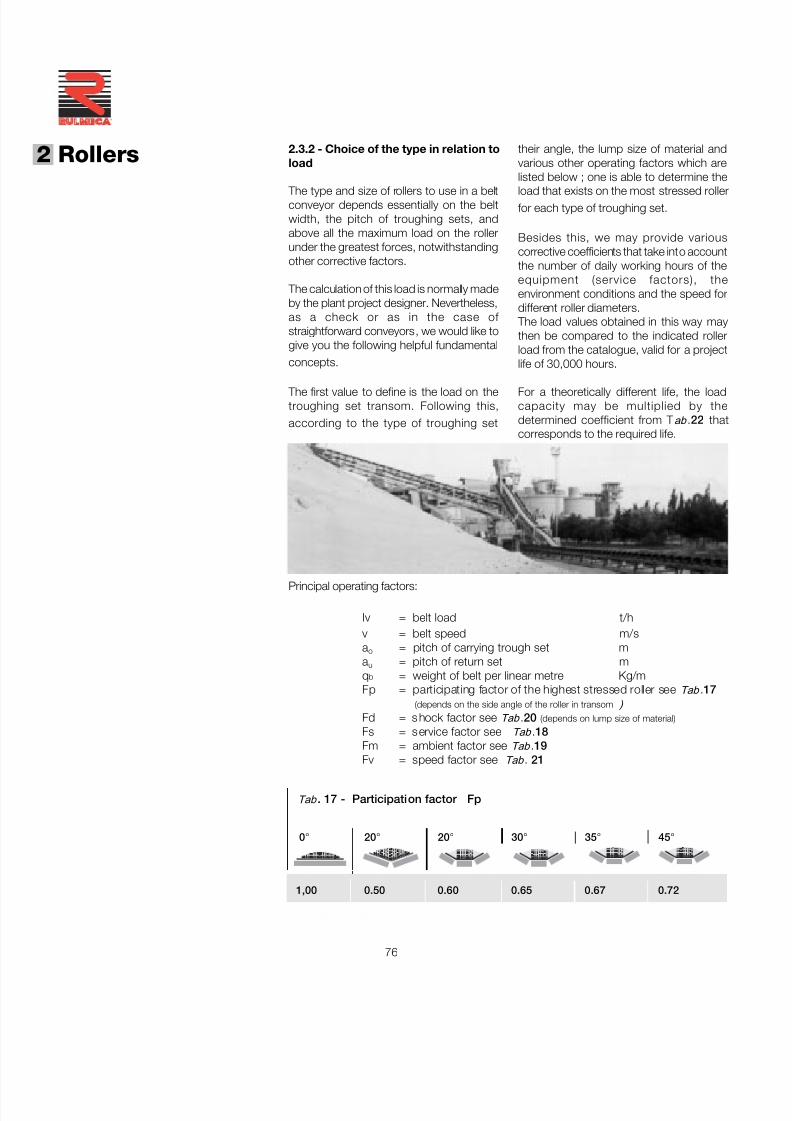
7/27/2019 31801183 Idler Roller
http://slidepdf.com/reader/full/31801183-idler-roller 78/308
76
®
2 Rollers
Principal operating factors:
Iv = belt load t/hv = belt speed m/sa o = pitch of carrying trough set ma u = pitch of return set mq b = weight of belt per linear metre Kg/mFp = participating factor of the highest stressed roller see Tab .17
(depends on the side angle of the roller in transom ) Fd = s hock factor see Tab .20 (depends on lump size of material)
Fs = s ervice factor see Tab .18Fm = ambient factor see Tab .19Fv = speed factor see Tab . 21
2.3.2 - Choice of the type in relat ion toload
The type and size of rollers to use in a beltconveyor depends essentially on the beltwidth, the pitch of troughing sets, andabove all the maximum load on the rollerunder the greatest forces, notwithstandingother corrective factors.
The calculation of this load is normally madeby the plant project designer. Nevertheless,as a check or as in the case of straightforward conveyors, we would like togive you the following helpful fundamentalconcepts.
The first value to define is the load on thetroughing set transom. Following this,according to the type of troughing set
their angle, the lump size of material andvarious other operating factors which arelisted below ; one is able to determine the
load that exists on the most stressed rollerfor each type of troughing set.
Besides this, we may provide variouscorrective coefficients that take into accountthe number of daily working hours of theequipment (service factors), theenvironment conditions and the speed fordifferent roller diameters.
The load values obtained in this way maythen be compared to the indicated rollerload from the catalogue, valid for a projectlife of 30,000 hours.
For a theoretically different life, the loadcapacity may be multiplied by thedetermined coefficient from T ab .22 thatcorresponds to the required life.
Tab . 17 - Participation factor Fp
0 ° 20 ° 20 ° 30 ° 35 ° 45 °
1,00 0.50 0.60 0.65 0.67 0.72
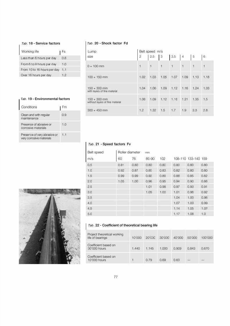
7/27/2019 31801183 Idler Roller
http://slidepdf.com/reader/full/31801183-idler-roller 79/308
77
Tab . 21 - Speed factors Fv
Belt speed Roller diameter mm
m/s 60 76 89-90 102 108-110 133-140 159
0.5 0.81 0.80 0.80 0.80 0.80 0.80 0.80
1.0 0.92 0.87 0.85 0.83 0.82 0.80 0.80
1.5 0.99 0.99 0.92 0.89 0.88 0.85 0.82
2.0 1.05 1.00 0.96 0.95 0.94 0.90 0.86
2.5 1.01 0.98 0.97 0.93 0.91
3.0 1.05 1.03 1.01 0.96 0.92
3.5 1.04 1.00 0.96
4.0 1.07 1.03 0.99
4.5 1.14 1.05 1.02
5.0 1.17 1.08 1.0
Tab . 22 - Coefficient of theoretical bearing life
Project theoretical workinglife of bearings 10'000 20'000 30'000 40'000 50'000 100'000
Coefficient based on30'000 hours 1.440 1.145 1.000 0.909 0.843 0.670
Coefficient based on10'000 hours 1 0.79 0.69 0.63 --- ---
Tab . 20 - Shock factor Fd
Lump Belt speed m/s
size 2 2.5 3 3.5 4 5 6
0 ÷ 100 mm 1 1 1 1 1 1 1
100 ÷ 150 mm 1.02 1.03 1.05 1.07 1.09 1.13 1.18
150 ÷ 300 mm 1.04 1.06 1.09 1.12 1.16 1.24 1.33with layers of fine material
150 ÷ 300 mm 1.06 1.09 1.12 1.16 1.21 1.35 1.5without layers of fine material
300 ÷ 450 mm 1.2 1.32 1.5 1.7 1.9 2.3 2.8
Tab . 18 - Service factors
Working life Fs
Less than 6 hours per day 0.8
From 6 to 9 hours per day 1.0
From 10 to 16 hours per day 1.1
Over 16 hours per day 1.2
Tab . 19 - Environmental factors
Conditions Fm
Clean and with regular 0.9maintenance
Presence of abrasive or 1.0corrosive materials
Presence of very abrasive or 1.1very corrosive materials
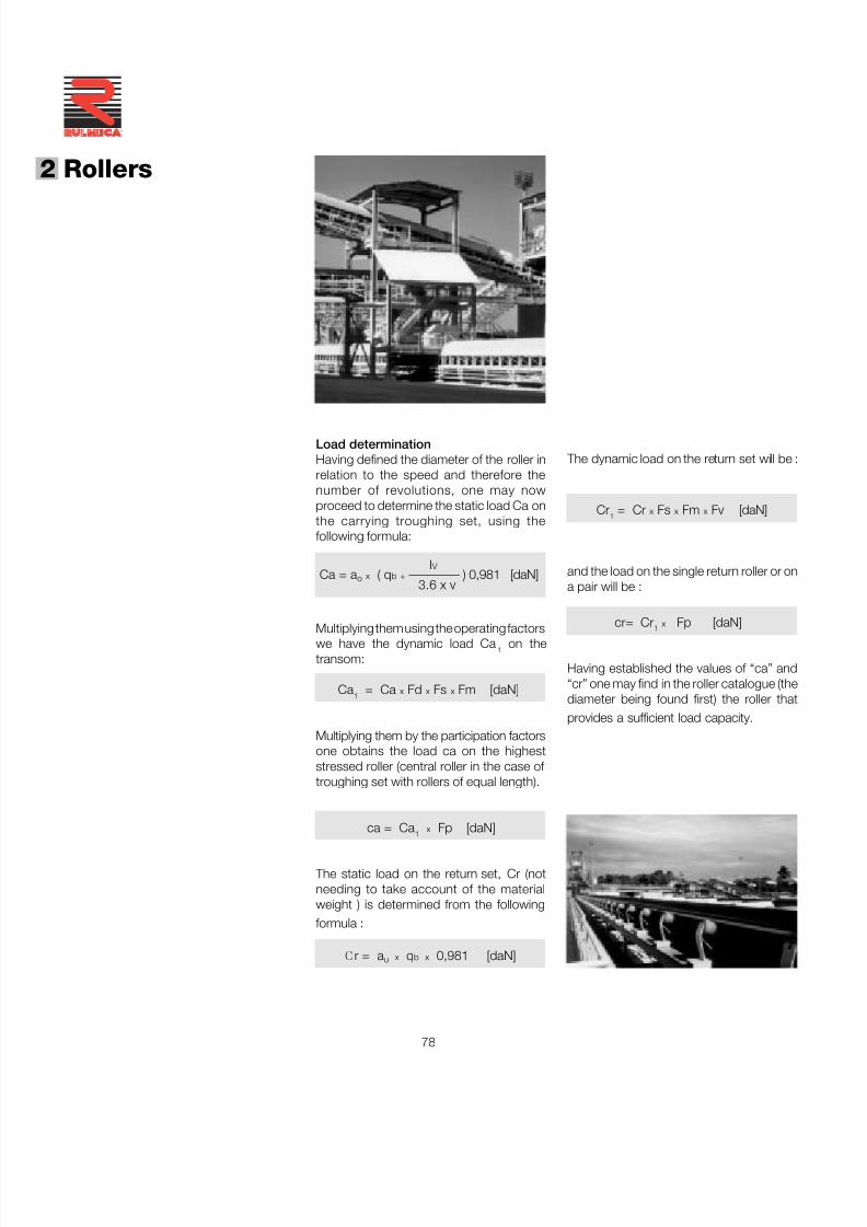
7/27/2019 31801183 Idler Roller
http://slidepdf.com/reader/full/31801183-idler-roller 80/308
78
®
2 Rollers
The dynamic load on the return set will be :
Cr 1 = Cr x Fs x Fm x Fv [daN]
and the load on the single return roller or ona pair will be :
cr= Cr 1 x Fp [daN]
Having established the values of “ca” and“cr” one may find in the roller catalogue (thediameter being found first) the roller thatprovides a sufficient load capacity.
Load determinationHaving defined the diameter of the roller inrelation to the speed and therefore thenumber of revolutions, one may nowproceed to determine the static load Ca onthe carrying troughing set, using thefollowing formula:
I V Ca = a o x ( q b + ———— ) 0,981 [daN]
3.6 x v
Multiplying them using the operating factorswe have the dynamic load Ca 1 on thetransom:
Ca 1 = Ca x Fd x Fs x Fm [daN]
Multiplying them by the participation factorsone obtains the load ca on the higheststressed roller (central roller in the case of troughing set with rollers of equal length).
ca = Ca 1 x Fp [daN]
The static load on the return set, Cr (notneeding to take account of the materialweight ) is determined from the followingformula :
C r = a u x q b x 0,981 [daN]
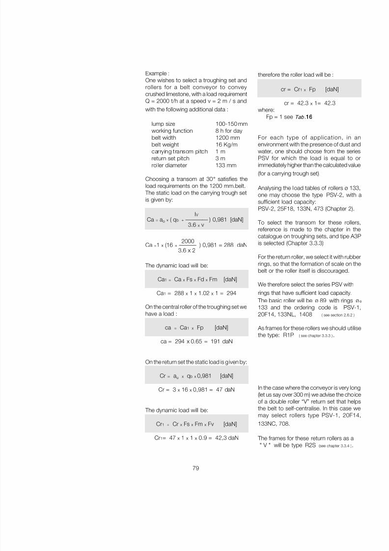
7/27/2019 31801183 Idler Roller
http://slidepdf.com/reader/full/31801183-idler-roller 81/308
79
Example :One wishes to select a troughing set androllers for a belt conveyor to convey
crushed limestone, with a load requirementQ = 2000 t/h at a speed v = 2 m / s andwith the following additional data :
lump size 100-150 mmworking function 8 h for daybelt width 1200 mmbelt weight 16 Kg/mcarrying transom pitch 1 mreturn set pitch 3 mroller diameter 133 mm
Choosing a transom at 30 ° satisfies theload requirements on the 1200 mm.belt.
The static load on the carrying trough setis given by:
I V Ca = a o x ( q b + ———— ) 0,981 [daN]
3.6 x v
2000Ca =1 x (16 + ——— ) 0,981 = 288 daN
3.6 x 2
The dynamic load will be:
Ca 1 = Ca x Fs x Fd x Fm [daN]
Ca 1 = 288 x 1 x 1.02 x 1 = 294
On the central roller of the troughing set wehave a load :
ca = Ca 1 x Fp [daN]
ca = 294 x 0.65 = 191 daN
On the return set the static load is given by:
Cr = au x q b x 0,981 [daN]
Cr = 3 x 16 x 0,981 = 47 daN
The dynamic load will be:
Cr1 = Cr x Fs x Fm x Fv [daN]
Cr1= 47 x 1 x 1 x 0.9 = 42,3 daN
therefore the roller load will be :
cr = Cr 1 x Fp [daN]
cr = 42.3 x 1= 42.3where:
Fp = 1 see Tab .16
For each type of application, in anenvironment with the presence of dust andwater, one should choose from the seriesPSV for which the load is equal to orimmediately higher than the calculated value(for a carrying trough set).
Analysing the load tables of rollers ø 133,one may choose the type PSV-2, with asufficient load capacity:PSV-2, 25F18, 133N, 473 (Chapter 2).
To select the transom for these rollers,reference is made to the chapter in thecatalogue on troughing sets, and tipe A3Pis selected (Chapter 3.3.3)
For the return roller, we select it with rubberrings, so that the formation of scale on thebelt or the roller itself is discouraged.
We therefore select the series PSV withrings that have sufficient load capacity.
The basic roller will be ø 89 with rings ø133 and the ordering code is PSV-1,20F14, 133NL, 1408 ( see section 2.6.2 )
As frames for these rollers we should utilisethe type: R1P ( see chapter 3.3.3 ) .
In the case where the conveyor is very long(let us say over 300 m) we advise the choiceof a double roller “V” return set that helpsthe belt to self-centralise. In this case wemay select rollers type PSV-1, 20F14,133NC, 708.
The frames for these return rollers as a" V " will be type R2S (see chapter 3.3.4 ) .
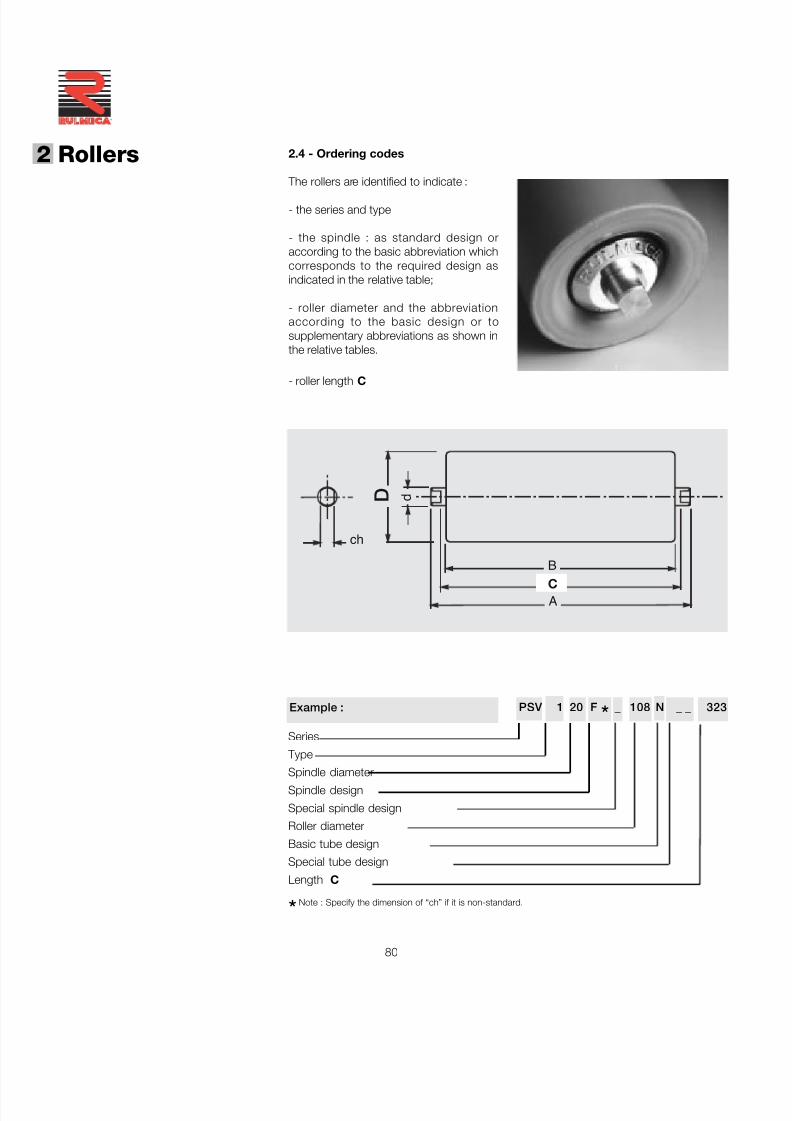
7/27/2019 31801183 Idler Roller
http://slidepdf.com/reader/full/31801183-idler-roller 82/308
80
®
2 Rollers
B
A
D
C
ch
d
2.4 - Ordering codes
The rollers are identified to indicate :
- the series and type
- the spindle : as standard design oraccording to the basic abbreviation whichcorresponds to the required design asindicated in the relative table;
- roller diameter and the abbreviationaccording to the basic design or tosupplementary abbreviations as shown inthe relative tables.
- roller length C
PSV 1 20 F * _ 108 N _ _ _ _323
Series
Type
Spindle diameterSpindle design
Special spindle design
Roller diameter
Basic tube design
Special tube design
Length C
Example :
*Note : Specify the dimension of “ch” if it is non-standard.
7/27/2019 31801183 Idler Roller
http://slidepdf.com/reader/full/31801183-idler-roller 83/308
81
On request standard design N may be supplied with the application of Tectyl 100 (valvoline) waxing oil thatprotects for transport and the initial period of storage (about 6 months).
Tube designs
Basic Description NoteAbbrev. Supplementary
In the first column of the table abbreviations are indicated according to the basic rollerdesigns.
There are supplementary designs possible as indicated in the table, as long as the
corresponding abbreviations are not represented in the same column.In the indication of the ordering code abbreviations are listed according to the horizontalcolumn order.
N steel S 235 JR (EN10027-1), ex Fe 360 (EN 10025), St37 (DIN 17100) Standard
I stainless steel AISI 304 Optional
V rigid PVC - colour grey - RAL 7011 Standard
S spiral metal cage Standard
J electrolytic zinc - colour grey - 10 micron thickness Standard
T rilsan coated - colour grey - PA 11- thickness 100/150 micron Optional
Y degreased - painted: one coat antirust and sprayed colour dark red -
thickness 40 micron Optional
A flat rubber rings for impact rollers Standard
G pointed rubber rings for flat return rollers Standard
L mixed design rubber rings for flat return rollers Standard
C mixed design rubber rings for "V" design return rollers Standard
M helical form rubber rings Standard
P rubber sheath in soft PVC - colour grey - hardness 68 Sh A Optional
R rubber covered - anti ageing - anti ozone - colour black -
black vulcanised - hardness 70/75 Sh A - turned - thickness as required Optional
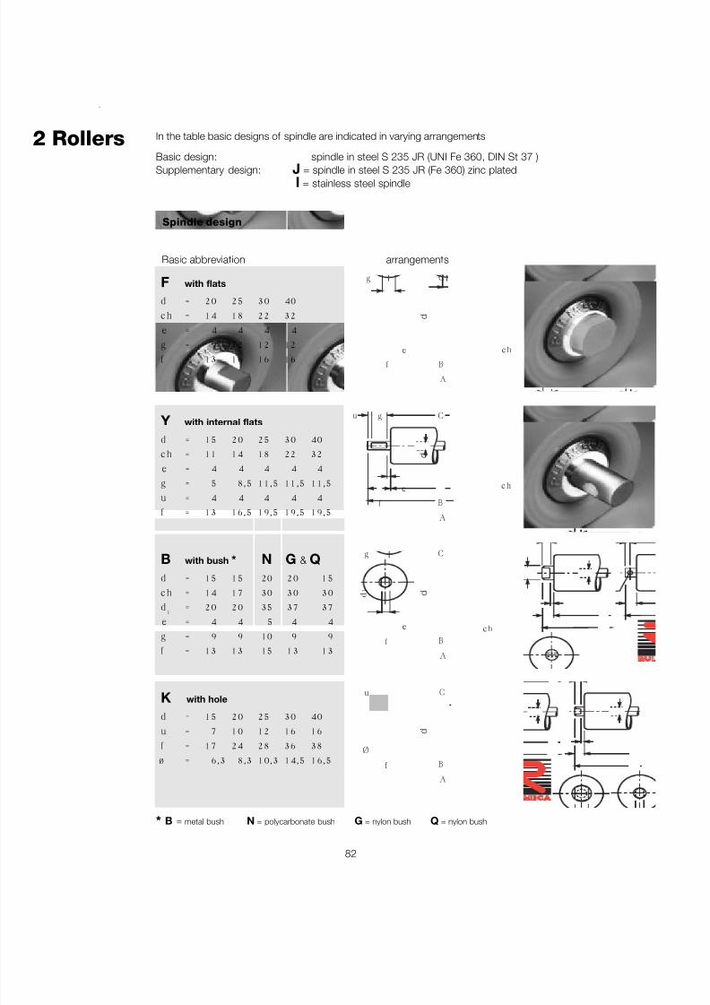
7/27/2019 31801183 Idler Roller
http://slidepdf.com/reader/full/31801183-idler-roller 84/308
82
®
2 Rollers In the table basic designs of spindle are indicated in varying arrangements
Basic design: spindle in steel S 235 JR (UNI Fe 360, DIN St 37 )
Supplementary design: J = spindle in steel S 235 JR (Fe 360) zinc platedI = stainless steel spindle
Spindle design
Basic abbreviation arrangements
F with flats
d = 20 25 30 40c h = 14 18 22 32e = 4 4 4 4
g = 9 12 12 12f = 13 16 16 16
Y with internal flats
d = 15 20 25 30 40c h = 11 14 18 22 32e = 4 4 4 4 4g = 5 8,5 11,5 11,5 11,5u = 4 4 4 4 4f = 13 16,5 19,5 19,5 19,5
B with bush *
d = 15 15c h = 14 17d 1 = 20 20e = 4 4g = 9 9f = 13 13
N203035
51015
G & Q20 1530 3037 374 49 9
13 13
K with hole
d = 15 20 25 30 40u = 7 10 12 16 16f = 17 24 28 36 38ø = 6,3 8,3 10,3 14,5 16,5
Cu
f B
A
Ø
d
ch
Cg
e
f B
A
d 1
d
c h
Cgu
f
e
B
A
d
d
c h
Cg
e
f B
A
* B = metal bush N = polycarbonate bush G = nylon bush Q = nylon bush
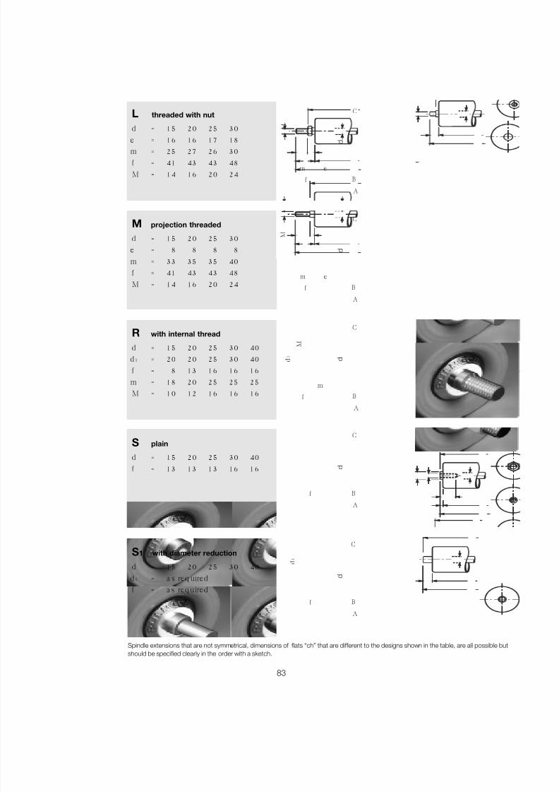
7/27/2019 31801183 Idler Roller
http://slidepdf.com/reader/full/31801183-idler-roller 85/308
83
L threaded with nut
d = 15 20 25 30e = 16 16 17 18m = 25 27 26 30f = 41 43 43 48M = 14 16 20 24
M projection threaded
d = 15 20 25 30e = 8 8 8 8m = 33 35 35 40
f = 41 43 43 48M = 14 16 20 24
R with internal thread
d = 15 20 25 30 40d 1 = 20 20 25 30 40f = 8 13 16 16 16m = 18 20 25 25 25M = 10 12 16 16 16
S plain
d = 15 20 25 30 40f = 13 13 13 16 16
S 1 with diameter reduction
d = 15 20 25 30 40d 1 = a s req uiredf = a s req uired
Spindle extensions that are not symmetrical, dimensions of flats “ch” that are different to the designs shown in the table, are all possible butshould be specified clearly in the order with a sketch.
B
A
f
C
d
B
A
f
C
d 1
d
C
B
A
f
m
d 1
M
d
m e
C
B
A
f
M
d
C
e
B
A
f
m
M
d
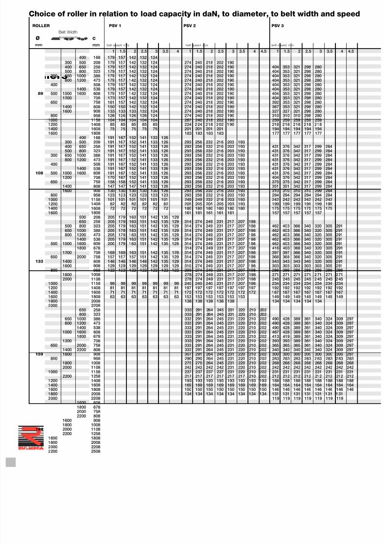
7/27/2019 31801183 Idler Roller
http://slidepdf.com/reader/full/31801183-idler-roller 86/308
84
®
2 Rollers
ROLLER PSV 1 PSV 2 PSV 3
Belt Width
Ø Arrangements C
mm mm belt speed m/s belt speed m/s belt speed m/s
1 1.5 2 2.5 3 3.5 4 1 1.5 2 2.5 3 3.5 4 4.5 1 1.5 2 2.5 3 3.5 4 4.5400 168 179 157 142 132 124
300 500 208 179 157 142 132 124 274 240 218 202 190400 650 258 179 157 142 132 124 274 240 218 202 190 404 353 321 298 280500 800 323 179 157 142 132 124 274 240 218 202 190 404 353 321 298 280
300 650 1000 388 179 157 142 132 124 274 240 218 202 190 404 353 321 298 280800 1200 473 179 157 142 132 124 274 240 218 202 190 404 353 321 298 280
400 508 179 157 142 132 124 274 240 218 202 190 404 353 321 298 2801400 538 179 157 142 132 124 274 240 218 202 190 404 353 321 298 280
89 500 1000 1600 608 179 157 142 132 124 274 240 218 202 190 404 353 321 298 2801200 708 173 157 142 132 124 274 240 218 202 190 404 353 321 298 280
650 758 161 157 142 132 124 274 240 218 202 190 392 353 321 298 2801400 808 150 150 142 132 124 274 240 218 202 190 367 353 321 298 2801600 908 133 133 133 132 124 274 240 218 202 190 327 327 321 298 280
800 958 126 126 126 126 124 274 240 218 202 190 310 310 310 298 2801000 1158 104 104 104 104 104 267 240 218 202 190 259 259 259 259 2591200 1408 85 85 85 85 85 224 224 218 202 190 218 218 218 218 2181400 1608 75 75 75 75 75 201 201 201 201 194 194 194 194 1941600 1808 183 183 183 183 177 177 177 177 177
400 168 191 167 152 141 133 126300 500 208 191 167 152 141 133 126 293 256 232 216 203 193400 650 258 191 167 152 141 133 126 293 256 232 216 203 193 431 376 342 317 299 284500 800 323 191 167 152 141 133 126 293 256 232 216 203 193 431 376 342 317 299 284
300 650 1000 388 191 167 152 141 133 126 293 256 232 216 203 193 431 376 342 317 299 284800 1200 473 191 167 152 141 133 126 293 256 232 216 203 193 431 376 342 317 299 284
400 508 191 167 152 141 133 126 293 256 232 216 203 193 431 376 342 317 299 2841400 538 191 167 152 141 133 126 293 256 232 216 203 193 431 376 342 317 299 284
108 500 1000 1600 608 191 167 152 141 133 126 293 256 232 216 203 193 431 376 342 317 299 2841200 708 170 167 152 141 133 126 293 256 232 216 203 193 404 376 342 317 299 284
650 758 158 158 152 141 133 126 293 256 232 216 203 193 375 375 342 317 299 284
1400 808 147 147 147 141 133 126 293 256 232 216 203 193 351 351 342 317 299 2841600 908 130 130 130 130 130 126 293 256 232 216 203 193 310 310 310 310 299 284800 958 123 123 123 123 123 123 293 256 232 216 203 193 294 294 294 294 294 284
1000 1158 101 101 101 101 101 101 249 249 232 216 203 193 242 242 242 242 242 2421200 1408 82 82 82 82 82 82 205 205 205 205 203 193 199 199 199 199 199 1991400 1608 72 72 72 72 72 72 180 180 180 180 180 180 175 175 175 175 175 1751600 1808 161 161 161 161 161 157 157 157 157 157
500 208 205 179 163 151 142 135 129650 258 205 179 163 151 142 135 129 314 274 249 231 217 207 198
500 800 323 205 179 163 151 142 135 129 314 274 249 231 217 207 198 462 403 366 340 320 305 291650 1000 388 205 179 163 151 142 135 129 314 274 249 231 217 207 198 462 403 366 340 320 305 291800 1200 473 205 179 163 151 142 135 129 314 274 249 231 217 207 198 462 403 366 340 320 305 291
1400 538 205 179 163 151 142 135 129 314 274 249 231 217 207 198 462 403 366 340 320 305 291500 1000 1600 608 200 179 163 151 142 135 129 314 274 249 231 217 207 198 462 403 366 340 320 305 291
1800 678 314 274 249 231 217 207 198 416 403 366 340 320 305 2911200 708 169 169 163 151 142 135 129 314 274 249 231 217 207 198 397 397 366 340 320 305 291
650 2000 758 157 157 157 151 142 135 129 314 274 249 231 217 207 198 368 368 366 340 320 305 291133 1400 808 146 146 146 146 142 135 129 314 274 249 231 217 207 198 343 343 343 340 320 305 291
1600 908 129 129 129 129 129 129 129 310 274 249 231 217 207 198 303 303 303 303 303 305 291800 958 122 122 122 122 122 122 122 293 274 249 231 217 207 198 286 286 286 286 286 286 286
1800 1008 278 274 249 231 217 207 198 271 271 271 271 271 271 271
2000 1108 278 274 249 231 217 207 198 245 245 245 245 245 245 2451000 1158 99 99 99 99 99 99 99 240 240 240 231 217 207 198 234 234 234 234 234 234 2341200 1408 81 81 81 81 81 81 81 197 197 197 197 197 197 197 192 192 192 192 192 192 1921400 1608 71 71 71 71 71 71 71 172 172 172 172 172 172 172 167 167 167 167 167 167 1671600 1808 63 63 63 63 63 63 63 153 153 153 153 153 153 149 149 149 149 149 149 1491800 2008 138 138 138 138 138 134 134 134 134 1342000 2208
650 258 333 291 264 245 231 220 210 202800 323 333 291 264 245 231 220 210 202
650 1000 388 333 291 264 245 231 220 210 202 490 428 389 361 340 324 309 297800 1200 473 333 291 264 245 231 220 210 202 490 428 389 361 340 324 309 297
1400 538 333 291 264 245 231 220 210 202 490 428 389 361 340 324 309 2971000 1600 608 333 291 264 245 231 220 210 202 467 428 389 361 340 324 309 297
1800 678 333 291 264 245 231 220 210 202 413 419 389 361 340 324 309 2971200 708 333 291 264 245 231 220 210 202 393 393 389 361 340 324 309 297
650 2000 758 333 291 264 245 231 220 210 202 365 365 365 361 340 324 309 2971400 2200 808 333 291 264 245 231 220 210 202 340 340 340 340 340 324 309 297
159 1600 908 307 291 264 245 231 220 210 202 300 300 300 300 300 300 300 297800 958 290 290 264 245 231 220 210 202 283 283 283 283 283 283 283 283
1800 1008 275 275 264 245 231 220 210 202 268 268 268 268 268 268 268 2682000 1108 242 242 242 242 231 220 210 202 242 242 242 242 242 242 242 242
1000 1158 237 237 237 237 231 220 210 202 231 231 231 231 231 231 231 2312200 1258 217 217 217 217 217 217 210 202 212 212 212 212 212 212 212 212
1200 1408 193 193 193 193 193 193 193 193 188 188 188 188 188 188 188 1881400 1608 169 169 169 169 169 169 169 169 164 164 164 164 164 164 164 1641600 1808 150 150 150 150 150 150 150 150 146 146 146 146 146 146 146 1461800 2008 134 134 134 134 134 134 134 134 131 131 131 131 131 131 1312000 2208 119 119 119 119 119 119 119
1600 6081800 6782000 7582200 808
1600 9081800 1008
194 2000 11082200 1258
1600 18081800 20082000 22082200 2508
Choice of roller in relation to load capacity in daN, to diameter, to belt width and speed
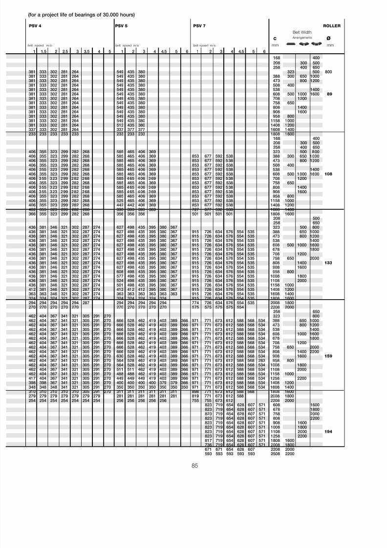
7/27/2019 31801183 Idler Roller
http://slidepdf.com/reader/full/31801183-idler-roller 87/308
85
PSV 4 PSV 5 PSV 7 ROLLER
Belt Width
C Arrangements Øbelt speed m/s belt speed m/s belt speed m/s mm mm
1 1.5 2 2.5 3 3.5 4 5 1 2 3 4 4.5 5 6 1 2 3 4 4.5 5 6168 400208 300 500258 400 650
381 333 302 281 264 549 435 380 323 500 800381 333 302 281 264 549 435 380 388 300 650 1000381 333 302 281 264 549 435 380 473 800 1200381 333 302 281 264 549 435 380 508 400381 333 302 281 264 549 435 380 538 1400381 333 302 281 264 549 435 380 608 500 1000 1600 89381 333 302 281 264 549 435 380 708 1200381 333 302 281 264 549 435 380 758 650381 333 302 281 264 549 435 380 808 1400381 333 302 281 264 549 435 380 908 1600381 333 302 281 264 549 435 380 958 800381 333 302 281 264 549 435 380 1158 1000381 333 302 281 264 512 435 380 1408 1200337 333 302 281 264 337 377 377 1608 1400233 233 233 233 233 233 233 233 1808 1600
168 400208 300 500258 400 650
406 355 323 299 282 268 585 465 406 369 323 500 800406 355 323 299 282 268 585 465 406 369 853 677 592 538 388 300 650 1000406 355 323 299 282 268 585 465 406 369 853 677 592 538 473 800 1200406 355 323 299 282 268 585 465 406 369 853 677 592 538 508 400406 355 323 299 282 268 585 465 406 369 853 677 592 538 538 1400406 355 323 299 282 268 585 465 406 369 853 677 592 538 608 500 1000 1600 108406 355 323 299 282 268 585 465 406 369 853 677 592 538 708 1200406 355 323 299 282 268 585 465 406 369 853 677 592 538 758 650
406 355 323 299 282 268 585 465 406 369 853 677 592 538 808 1400406 355 323 299 282 268 585 465 406 369 853 677 592 538 908 1600406 355 323 299 282 268 585 465 406 369 853 677 592 538 958 800406 355 323 299 282 268 529 465 406 369 853 677 592 538 1158 1000406 355 323 299 282 268 442 442 406 369 853 677 592 538 1408 1200402 355 323 299 282 268 393 393 393 369 727 677 592 538 1608 1400366 355 323 299 282 268 356 356 356 501 501 501 501 1808 1600
208 500258 650
436 381 346 321 302 287 274 627 498 435 395 380 367 323 500 800436 381 346 321 302 287 274 627 498 435 395 380 367 915 726 634 576 554 535 388 650 1000436 381 346 321 302 287 274 627 498 435 395 380 367 915 726 634 576 554 535 473 800 1200436 381 346 321 302 287 274 627 498 435 395 380 367 915 726 634 576 554 535 538 1400436 381 346 321 302 287 274 627 498 435 395 380 367 915 726 634 576 554 535 608 500 1000 1600436 381 346 321 302 287 274 627 498 435 395 380 367 915 726 634 576 554 535 678 1800436 381 346 321 302 287 274 627 498 435 395 380 367 915 726 634 576 554 535 708 1200436 381 346 321 302 287 274 627 498 435 395 380 367 915 726 634 576 554 535 758 650 2000436 381 346 321 302 287 274 627 498 435 395 380 367 915 726 634 576 554 535 808 1400 133436 381 346 321 302 287 274 627 498 435 395 380 367 915 726 634 576 554 535 908 1600436 381 346 321 302 287 274 608 498 435 395 380 367 915 726 634 576 554 535 958 800436 381 346 321 302 287 274 577 498 435 395 380 367 915 726 634 576 554 535 1008 1800
436 381 346 321 302 287 274 524 498 435 395 380 367 915 726 634 576 554 535 1108 2000436 381 346 321 302 287 274 501 498 435 395 380 367 915 726 634 576 554 535 1158 1000412 381 346 321 302 287 274 412 412 412 395 380 367 915 726 634 576 554 535 1408 1200363 363 346 321 302 287 274 363 363 363 363 363 363 915 726 634 576 554 535 1608 1400324 324 324 321 302 287 274 324 324 324 324 324 915 726 634 576 554 535 1808 1600294 294 294 294 294 287 294 294 294 294 294 774 726 634 576 554 535 2008 1800270 270 270 270 270 270 270 270 270 270 575 575 575 575 554 2208 2000
258 650462 404 367 341 321 305 291 270 323 800462 404 367 341 321 305 291 270 666 528 462 419 403 389 366 971 771 673 612 588 568 534 388 650 1000462 404 367 341 321 305 291 270 666 528 462 419 403 389 366 971 771 673 612 588 568 534 473 800 1200462 404 367 341 321 305 291 270 666 528 462 419 403 389 366 971 771 673 612 588 568 534 538 1400462 404 367 341 321 305 291 270 666 528 462 419 403 389 366 971 771 673 612 588 568 534 608 1000 1600462 404 367 341 321 305 291 270 666 528 462 419 403 389 366 971 771 673 612 588 568 534 678 1800462 404 367 341 321 305 291 270 666 528 462 419 403 389 366 971 771 673 612 588 568 534 708 1200462 404 367 341 321 305 291 270 666 528 462 419 403 389 366 971 771 673 612 588 568 534 758 650 2000462 404 367 341 321 305 291 270 666 528 462 419 403 389 366 971 771 673 612 588 568 534 808 1400 2200462 404 367 341 321 305 291 270 630 528 462 419 403 389 366 971 771 673 612 588 568 534 908 1600 159462 404 367 341 321 305 291 270 564 528 462 419 403 389 366 971 771 673 612 588 568 283 958 800462 404 367 341 321 305 291 270 564 528 462 419 403 389 366 971 771 673 612 588 568 534 1008 1800462 404 367 341 321 305 291 270 511 511 462 419 403 389 366 971 771 673 612 588 568 534 1108 2000462 404 367 341 321 305 291 270 488 488 462 419 403 389 366 971 771 673 612 588 568 534 1158 1000417 404 367 341 321 305 291 270 449 449 449 419 403 389 366 971 771 673 612 588 568 534 1258 2200398 398 367 341 321 305 291 270 400 400 400 400 379 379 366 971 771 673 612 588 568 534 1408 1200348 348 348 341 321 305 291 270 350 350 350 350 350 350 350 971 771 673 612 588 568 534 1608 1400310 310 310 310 310 305 291 270 311 311 311 311 311 311 898 771 673 612 588 568 1808 1600279 279 279 279 279 279 279 281 281 281 281 281 281 819 771 673 612 588 2008 1800254 254 254 254 254 254 254 256 256 256 256 256 755 755 673 612 2208 2000
823 719 654 628 607 571 608 1600823 719 654 628 607 571 678 1800823 719 654 628 607 571 758 2000823 719 654 628 607 571 808 2200823 719 654 628 607 571 908 1600823 719 654 628 607 571 1008 1800823 719 654 628 607 571 1108 2000 194823 719 654 628 607 571 1258 2200817 719 654 628 607 571 1808 1600736 719 654 628 607 571 2008 1800671 671 654 628 607 2208 2000593 593 593 593 593 2508 2200
(for a project life of bearings of 30.000 hours)
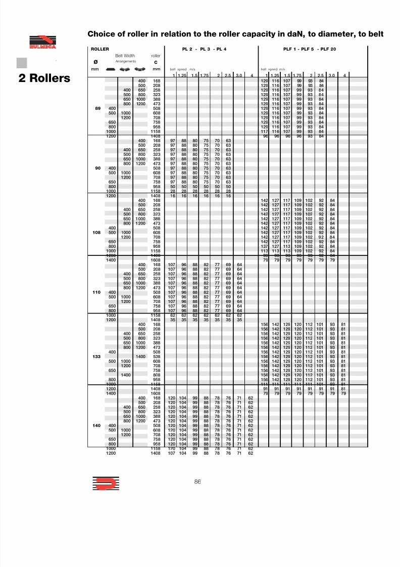
7/27/2019 31801183 Idler Roller
http://slidepdf.com/reader/full/31801183-idler-roller 88/308
86
®
2 Rollers
ROLLER PL 2 - PL 3 - PL 4 PLF 1 - PLF 5 - PLF 20
Belt Width roller
Ø Arrangements C
mm mm belt speed m/s belt speed m/s
1 1.25 1.5 1.75 2 2.5 3.0 4 1 1.25 1.5 1.75 2 2.5 3.0 4400 168 129 116 107 99 93 84500 208 129 116 107 99 93 84
400 650 258 129 116 107 99 93 84500 800 323 129 116 107 99 93 84650 1000 388 129 116 107 99 93 84800 1200 473 129 116 107 99 93 84
89 400 508 129 116 107 99 93 84500 1000 608 129 116 107 99 93 84
1200 708 129 116 107 99 93 84650 758 129 116 107 99 93 84800 958 129 116 107 99 93 84
1000 1158 117 116 107 99 93 841200 1408 96 96 96 96 93 84
400 168 97 88 80 75 70 63500 208 97 88 80 75 70 63
400 650 258 97 88 80 75 70 63500 800 323 97 88 80 75 70 63650 1000 388 97 88 80 75 70 63800 1200 473 97 88 80 75 70 63
90 400 508 97 88 80 75 70 63500 1000 608 97 88 80 75 70 63
1200 708 97 88 80 75 70 63650 758 97 88 80 75 70 63800 958 50 50 50 50 50 50
1000 1158 28 28 28 28 28 281200 1408 16 16 16 16 16 16
400 168 142 127 117 109 102 92 84500 208 142 127 117 109 102 92 84
400 650 258 142 127 117 109 102 92 84500 800 323 142 127 117 109 102 92 84650 1000 388 142 127 117 109 102 92 84800 1200 473 142 127 117 109 102 92 84
400 508 142 127 117 109 102 92 84108 500 1000 608 142 127 117 109 102 92 84
1200 708 142 127 117 109 102 92 84650 758 142 127 117 109 102 92 84800 958 137 127 113 109 102 92 84
1000 1158 113 113 113 109 102 92 841200 1408 93 93 93 93 93 92 841400 1608 79 79 79 79 79 79 79
400 168 107 96 88 82 77 69 64500 208 107 96 88 82 77 69 64
400 650 258 107 96 88 82 77 69 64500 800 323 107 96 88 82 77 69 64650 1000 388 107 96 88 82 77 69 64800 1200 473 107 96 88 82 77 69 64
110 400 508 107 96 88 82 77 69 64500 1000 608 107 96 88 82 77 69 64
1200 708 107 96 88 82 77 69 64650 758 107 96 88 82 77 69 64800 958 107 96 88 82 77 69 64
1000 1158 62 62 62 62 62 62 621200 1408 35 35 35 35 35 35 35
400 168 156 142 129 120 112 101 93 81500 208 156 142 129 120 112 101 93 81
400 650 258 156 142 129 120 112 101 93 81500 800 323 156 142 129 120 112 101 93 81650 1000 388 156 142 129 120 112 101 93 81800 1200 473 156 142 129 120 112 101 93 81
400 508 156 142 129 120 112 101 93 81133 1400 538 156 142 129 120 112 101 93 81
500 1000 608 156 142 129 120 112 101 93 811200 708 156 142 129 120 112 101 93 81
650 758 156 142 129 120 112 101 93 811400 808 156 142 129 120 112 101 93 81
800 958 156 142 129 120 112 101 93 811000 1158 111 111 111 111 111 101 93 81
1200 1408 91 91 91 91 91 91 91 811400 1608 79 79 79 79 79 79 79 79400 168 120 104 99 88 78 76 71 62500 208 120 104 99 88 78 76 71 62
400 650 258 120 104 99 88 78 76 71 62500 800 323 120 104 99 88 78 76 71 62650 1000 388 120 104 99 88 78 76 71 62800 1200 473 120 104 99 88 78 76 71 62
140 400 508 120 104 99 88 78 76 71 62500 1000 608 120 104 99 88 78 76 71 62
1200 708 120 104 99 88 78 76 71 62650 758 120 104 99 88 78 76 71 62800 958 120 104 99 88 78 76 71 62
1000 1158 120 104 99 88 78 76 71 621200 1408 107 104 99 88 78 76 71 62
Choice of roller in relation to the roller capacity in daN, to diameter, to belt
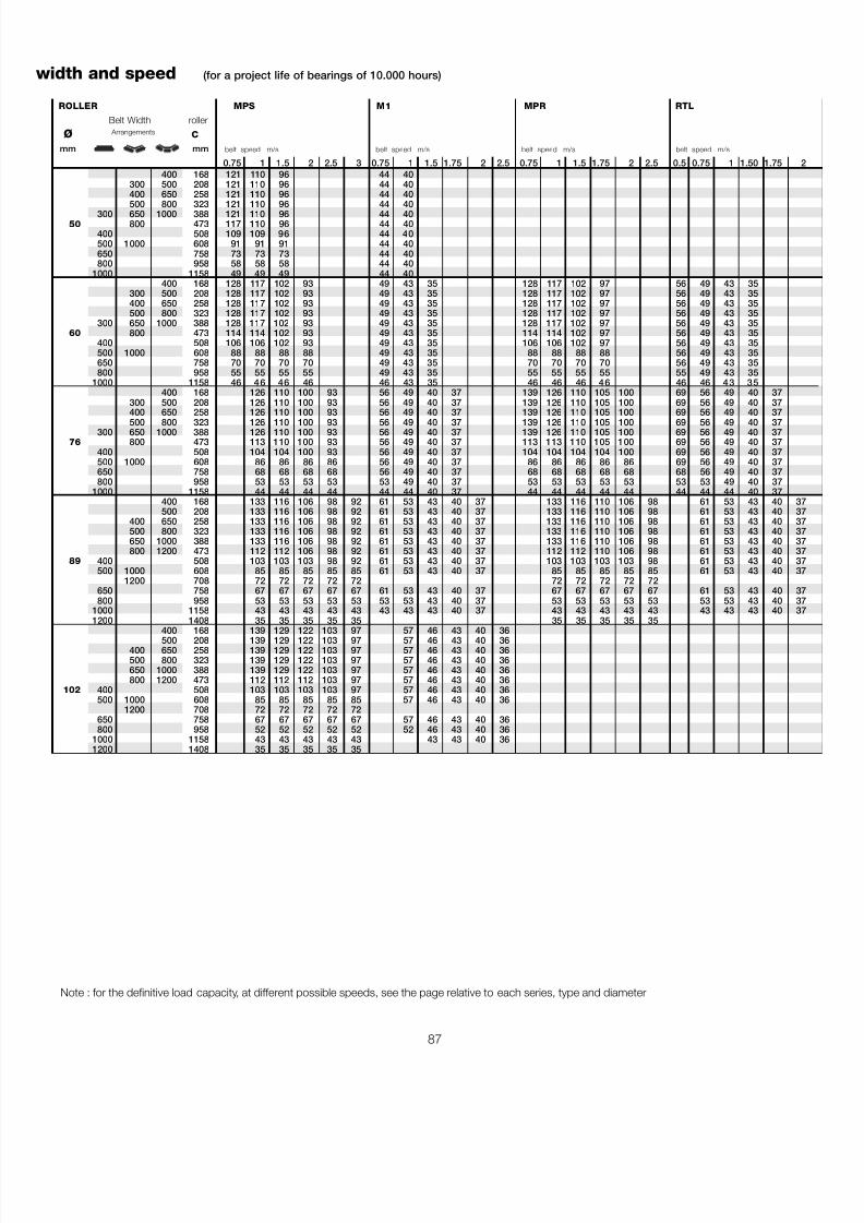
7/27/2019 31801183 Idler Roller
http://slidepdf.com/reader/full/31801183-idler-roller 89/308
87
ROLLER MPS M1 MPR RTL
Belt Width roller
Ø Arrangements C
mm mm belt speed m/s belt speed m/s belt speed m/s belt speed m/s
0.75 1 1.5 2 2.5 3 0.75 1 1.5 1.75 2 2.5 0.75 1 1.5 1.75 2 2.5 0.5 0.75 1 1.50 1.75 2400 168 121 110 96 44 40
300 500 208 121 110 96 44 40400 650 258 121 110 96 44 40500 800 323 121 110 96 44 40
300 650 1000 388 121 110 96 44 4050 800 473 117 110 96 44 40
400 508 109 109 96 44 40500 1000 608 91 91 91 44 40650 758 73 73 73 44 40800 958 58 58 58 44 40
1000 1158 49 49 49 44 40400 168 128 117 102 93 49 43 35 128 117 102 97 56 49 43 35
300 500 208 128 117 102 93 49 43 35 128 117 102 97 56 49 43 35400 650 258 128 117 102 93 49 43 35 128 117 102 97 56 49 43 35500 800 323 128 117 102 93 49 43 35 128 117 102 97 56 49 43 35
300 650 1000 388 128 117 102 93 49 43 35 128 117 102 97 56 49 43 3560 800 473 114 114 102 93 49 43 35 114 114 102 97 56 49 43 35
400 508 106 106 102 93 49 43 35 106 106 102 97 56 49 43 35500 1000 608 88 88 88 88 49 43 35 88 88 88 88 56 49 43 35650 758 70 70 70 70 49 43 35 70 70 70 70 56 49 43 35800 958 55 55 55 55 49 43 35 55 55 55 55 55 49 43 35
1000 1158 46 46 46 46 46 43 35 46 46 46 46 46 46 43 35400 168 126 110 100 93 56 49 40 37 139 126 110 105 100 69 56 49 40 37
300 500 208 126 110 100 93 56 49 40 37 139 126 110 105 100 69 56 49 40 37400 650 258 126 110 100 93 56 49 40 37 139 126 110 105 100 69 56 49 40 37500 800 323 126 110 100 93 56 49 40 37 139 126 110 105 100 69 56 49 40 37
300 650 1000 388 126 110 100 93 56 49 40 37 139 126 110 105 100 69 56 49 40 3776 800 473 113 110 100 93 56 49 40 37 113 113 110 105 100 69 56 49 40 37
400 508 104 104 100 93 56 49 40 37 104 104 104 104 100 69 56 49 40 37500 1000 608 86 86 86 86 56 49 40 37 86 86 86 86 86 69 56 49 40 37650 758 68 68 68 68 56 49 40 37 68 68 68 68 68 68 56 49 40 37800 958 53 53 53 53 53 49 40 37 53 53 53 53 53 53 53 49 40 37
1000 1158 44 44 44 44 44 44 40 37 44 44 44 44 44 44 44 44 40 37400 168 133 116 106 98 92 61 53 43 40 37 133 116 110 106 98 61 53 43 40 37500 208 133 116 106 98 92 61 53 43 40 37 133 116 110 106 98 61 53 43 40 37
400 650 258 133 116 106 98 92 61 53 43 40 37 133 116 110 106 98 61 53 43 40 37500 800 323 133 116 106 98 92 61 53 43 40 37 133 116 110 106 98 61 53 43 40 37650 1000 388 133 116 106 98 92 61 53 43 40 37 133 116 110 106 98 61 53 43 40 37800 1200 473 112 112 106 98 92 61 53 43 40 37 112 112 110 106 98 61 53 43 40 37
89 400 508 103 103 103 98 92 61 53 43 40 37 103 103 103 103 98 61 53 43 40 37500 1000 608 85 85 85 85 85 61 53 43 40 37 85 85 85 85 85 61 53 43 40 37
1200 708 72 72 72 72 72 72 72 72 72 72650 758 67 67 67 67 67 61 53 43 40 37 67 67 67 67 67 61 53 43 40 37800 958 53 53 53 53 53 53 53 43 40 37 53 53 53 53 53 53 53 43 40 37
1000 1158 43 43 43 43 43 43 43 43 40 37 43 43 43 43 43 43 43 43 40 371200 1408 35 35 35 35 35 35 35 35 35 35
400 168 139 129 122 103 97 57 46 43 40 36500 208 139 129 122 103 97 57 46 43 40 36
400 650 258 139 129 122 103 97 57 46 43 40 36500 800 323 139 129 122 103 97 57 46 43 40 36650 1000 388 139 129 122 103 97 57 46 43 40 36800 1200 473 112 112 112 103 97 57 46 43 40 36
102 400 508 103 103 103 103 97 57 46 43 40 36500 1000 608 85 85 85 85 85 57 46 43 40 36
1200 708 72 72 72 72 72650 758 67 67 67 67 67 57 46 43 40 36800 958 52 52 52 52 52 52 46 43 40 36
1000 1158 43 43 43 43 43 43 43 40 361200 1408 35 35 35 35 35
Note : for the definitive load capacity, at different possible speeds, see the page relative to each series, type and diameter
width and speed (for a project life of bearings of 10.000 hours)

7/27/2019 31801183 Idler Roller
http://slidepdf.com/reader/full/31801183-idler-roller 90/308
88
®
2 Rollers
7/27/2019 31801183 Idler Roller
http://slidepdf.com/reader/full/31801183-idler-roller 91/308
89
2.5 - Programme
The experience of Rulmeca for 40 years
producing belt conveyor rollers, hasperfected and expanded the range of products we offer, so that the user will findthe correct answer to the most diverse anddifficult applications,
This catalogue presents the different seriesof rollers in production and their relativeutilisation criteria :
1 - Rollers in steel series PSV 2 - Rollers in plastic series PL3 - Rollers in steel series MPS4 - Rollers in steel series MPR5 - Rollers in steel series RTL
1
2
3
4 5
7/27/2019 31801183 Idler Roller
http://slidepdf.com/reader/full/31801183-idler-roller 92/308
90
®
2 Rollers
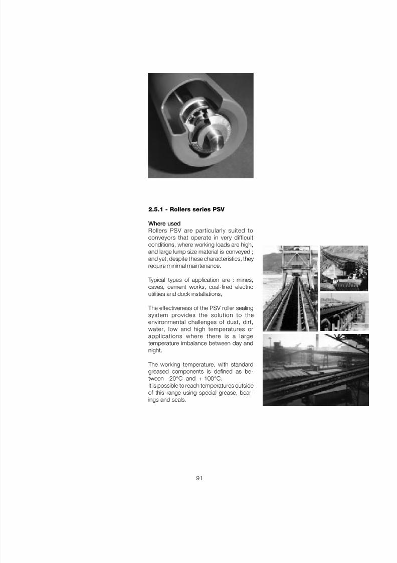
7/27/2019 31801183 Idler Roller
http://slidepdf.com/reader/full/31801183-idler-roller 93/308
91
2.5.1 - Rollers series PSV
Where usedRollers PSV are particularly suited toconveyors that operate in very difficultconditions, where working loads are high,and large lump size material is conveyed ;and yet, despite these characteristics, theyrequire minimal maintenance.
Typical types of application are : mines,caves, cement works, coal-fired electricutilities and dock installations,
The effectiveness of the PSV roller sealingsystem provides the solution to theenvironmental challenges of dust, dirt,water, low and high temperatures orapplications where there is a largetemperature imbalance between day andnight.
The working temperature, with standardgreased components is defined as be-tween -20 ° C and + 100 ° C.
It is possible to reach temperatures outsideof this range using special grease, bear-ings and seals.
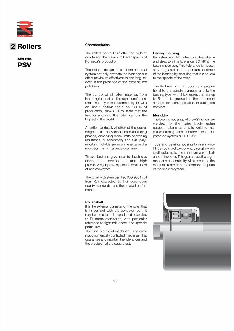
7/27/2019 31801183 Idler Roller
http://slidepdf.com/reader/full/31801183-idler-roller 94/308
92
®
2 Rollers
series
PSV
Bearing housingIt is a steel monolithic structure, deep drawnand sized to a fine tolerance ISO M7 at thebearing position, This tolerance is neces-sary to guarantee the optimum assemblyof the bearing by ensuring that it is squareto the spindle of the roller.
The thickness of the housings is propor-tional to the spindle diameter and to thebearing type, with thicknesses that are upto 5 mm, to guarantee the maximumstrength for each application, including theheaviest.
Monobloc The bearing housings of the PSV rollers arewelded to the tube body usingautocentralising automatic welding ma-chines utilising a continuous wire feed : ourpatented system “UNIBLOC”.
Tube and bearing housing form a mono-lithic structure of exceptional strength whichitself reduces to the minimum any imbal-ance in the roller, This guarantees the align-ment and concentricity with respect to theexternal diameter of the component parts
of the sealing system.
Characteristics
The rollers series PSV offer the highestquality and the maximum load capacity of Rulmeca’s production.
The unique design of our hermetic sealsystem not only protects the bearings butoffers maximum effectiveness and long life,even in the presence of the most severepollutants.
The control of all roller materials fromincoming inspection, through manufactureand assembly in the automatic cycle, withon line function tests on 100% of production, allows us to state that thefunction and life of this roller is among thehighest in the world.
Attention to detail, whether at the designstage or in the various manufacturingphases, observing close limits of startingresistance, of eccentricity and axial play,results in notable savings in energy and areduction in maintenance over time.
Th es e fact or s gi ve ri se to bu si ne sseconomies, confidence and highproductivity, objectives pursued by all users
of belt conveyors.
The Quality System certified ISO 9001 gotfrom Rulmeca attest to their continuousquality standards, and their stated perfor-mance.
Roller shellIt is the external diameter of the roller thatis in contact with the conveyor belt. Itconsists of a steel tube produced accordingto Rulmeca standards, with particularreference to tight tolerances and specific
particulars. The tube is cut and machined using auto-matic numerically controlled machines, thatguarantee and maintain the tolerances andthe precision of the square cut.
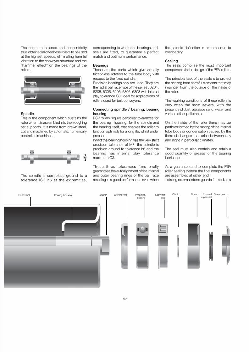
7/27/2019 31801183 Idler Roller
http://slidepdf.com/reader/full/31801183-idler-roller 95/308
93
corresponding to where the bearings andseals are fitted, to guarantee a perfectmatch and optimum performance.
Bearings These are the parts which give virtuallyfrictionless rotation to the tube body withrespect to the fixed spindle.Precision bearings only are used. They arethe radial ball race type of the series : 6204,6205, 6305, 6206, 6306, 6308 with internalplay tolerance C3, ideal for applications of rollers used for belt conveyors.
Connecting spindle / bearing, bearinghousingPSV rollers require particular tolerances forthe bearing housing, for the spindle andthe bearing itself, that enables the roller tofunction optimally for a long life, whilst underpressure.In fact the bearing housing has the very strictprecision tolerance of M7, the spindle isprecision ground to tolerance h6 and thebearing has internal play tolerancemaximum C3.
Th es e th ree to le ra nc es fu nc ti on al lyguarantees the autoalignment of the internaland outer bearing rings of the ball race
resulting in a good performance even when
The optimum balance and concentricitythus obtained allows these rollers to be usedat the highest speeds, eliminating harmfulvibration to the conveyor structure and the“hammer effect” on the bearings of therollers.
Spindle This is the component which sustains theroller when it is assembled into the troughingset supports. It is made from drawn steel,cut and machined by automatic numericallycontrolled machines.
The spindle is centreless ground to a
tolerance ISO h6 at the extremities,
Bearing housing Spindle Internal seal Precisionbearing
Labyrinthseal
Circlip Cover Stone guardExternalwiper seal
Roller shell
h 6
the spindle deflection is extreme due tooverloading.
Sealing The seals comprise the most importantcomponents in the design of the PSV rollers.
The principal task of the seals is to protectthe bearing from harmful elements that mayimpinge from the outside or the inside of the roller.
The working conditions of these rollers isvery often the most severe, with thepresence of dust, abrasive sand, water, andvarious other pollutants.
On the inside of the roller there may beparticles formed by the rusting of the internaltube body or condensation caused by thethermal changes that arise between dayand night in particular climates.
The seal must also contain and retain agood quantity of grease for the bearinglubrication.
As a guarantee and to complete the PSV roller sealing system the final componentsare assembled at either end :
- strong external stone guards formed as a
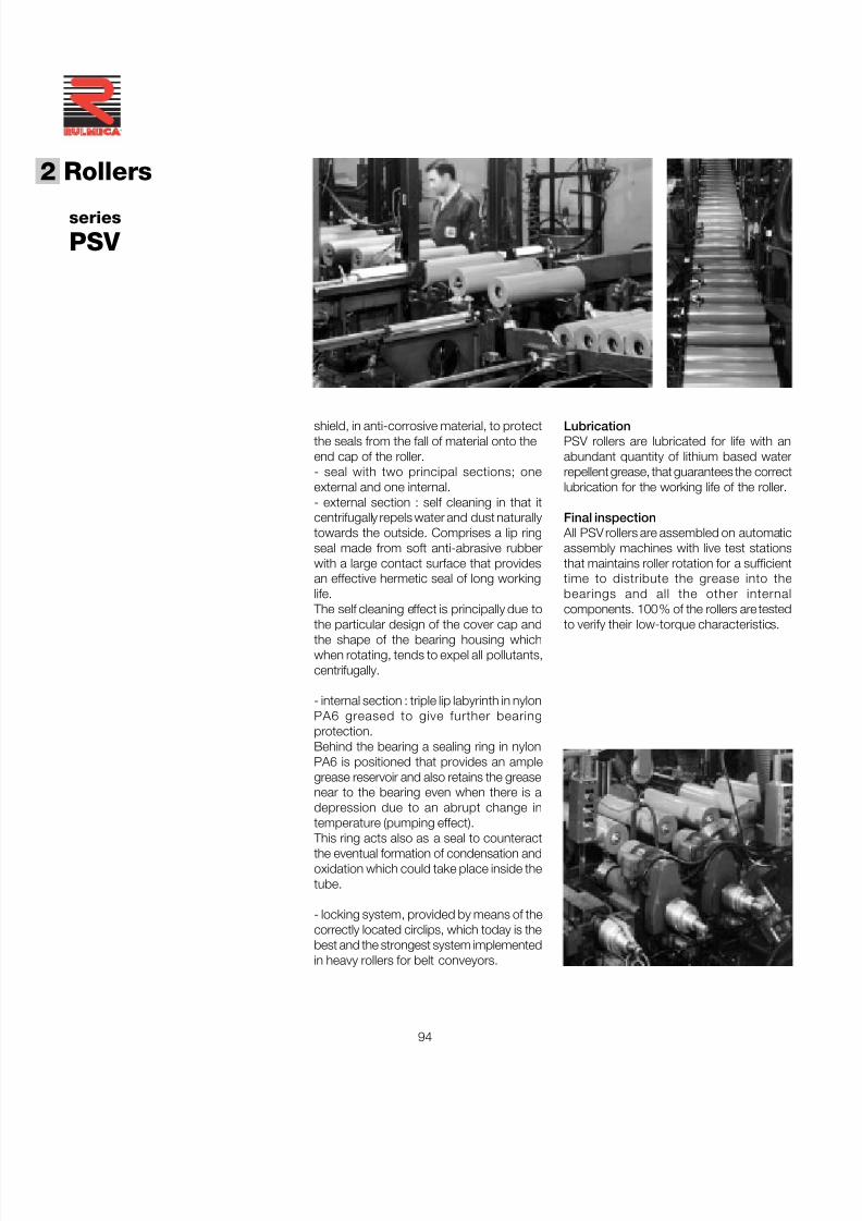
7/27/2019 31801183 Idler Roller
http://slidepdf.com/reader/full/31801183-idler-roller 96/308
94
®
2 Rollers
series
PSV
LubricationPSV rollers are lubricated for life with anabundant quantity of lithium based waterrepellent grease, that guarantees the correctlubrication for the working life of the roller.
Final inspection All PSV rollers are assembled on automaticassembly machines with live test stationsthat maintains roller rotation for a sufficienttime to distribute the grease into thebearings and all the other internalcomponents. 100% of the rollers are tested
to verify their low-torque characteristics.
shield, in anti-corrosive material, to protectthe seals from the fall of material onto theend cap of the roller.- seal with two principal sections; oneexternal and one internal.- external section : self cleaning in that itcentrifugally repels water and dust naturallytowards the outside. Comprises a lip ringseal made from soft anti-abrasive rubberwith a large contact surface that providesan effective hermetic seal of long workinglife.
The self cleaning effect is principally due to
the particular design of the cover cap andthe shape of the bearing housing whichwhen rotating, tends to expel all pollutants,centrifugally.
- internal section : triple lip labyrinth in nylonPA6 greased to give further bearingprotection.Behind the bearing a sealing ring in nylonPA6 is positioned that provides an amplegrease reservoir and also retains the greasenear to the bearing even when there is adepression due to an abrupt change intemperature (pumping effect).
This ring acts also as a seal to counteractthe eventual formation of condensation andoxidation which could take place inside thetube.
- locking system, provided by means of thecorrectly located circlips, which today is thebest and the strongest system implementedin heavy rollers for belt conveyors.
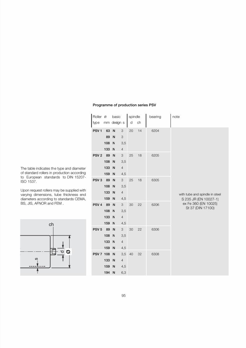
7/27/2019 31801183 Idler Roller
http://slidepdf.com/reader/full/31801183-idler-roller 97/308
95
ø d
s
ch
The table indicates the type and diameterof standard rollers in production accordingto European standards to DIN 15207-ISO 1537.
Upon request rollers may be supplied withvarying dimensions, tube thickness enddiameters according to standards CEMA,BS, JIS, AFNOR and FEM .
Programme of production series PSV
Roller ø basic spindle bearing note
type mm design s d ch
PSV 1 63 N 3 20 14 6204
89 N 3
108 N 3,5
133 N 4
PSV 2 89 N 3 25 18 6205
108 N 3,5
133 N 4
159 N 4,5
PSV 3 89 N 3 25 18 6305
108 N 3,5
133 N 4
159 N 4,5
PSV 4 89 N 3 30 22 6206
108 N 3,5
133 N 4
159 N 4,5
PSV 5 89 N 3 30 22 6306
108 N 3,5
133 N 4
159 N 4,5
PSV 7 108 N 3,5 40 32 6308
133 N 4
159 N 4,5
194 N 6,3
with tube and spindle in steelS 235 JR (EN 10027-1)ex Fe 360 (EN 10025)
St 37 (DIN 17100)

7/27/2019 31801183 Idler Roller
http://slidepdf.com/reader/full/31801183-idler-roller 98/308
96
®
2 Rollers
series
PSV 1
Ø 63 N
Bearing 6204( 20 X 47 X 14 )
d = 20ch = 14
s = 3e = 4g = 9
Example of orderingstandard designPSV1,20F,63N,608for special designsee pages 80-81
Belt roller
width dimensions weight load capacitymm mm Kg daN
arrangements rotating belt speed m/s
B C A parts total 0.5 1 1.25 1.5 1.75 2
400 160 168 186 1.3 1.8 201 160 148 140 133 127
300 500 200 208 226 1.5 2.1 201 160 148 140 133 127
400 650 250 258 276 1.7 2.4 201 160 148 140 133 127
500 800 315 323 341 2.0 2.9 201 160 148 140 133 127
300 650 1000 380 388 406 2.3 3.3 201 160 148 140 133 127
800 1200 465 473 491 2.7 3.9 201 160 148 140 133 127
400 500 508 526 2.9 4.1 201 160 148 140 133 127
500 1000 600 608 626 3.3 4.8 201 160 148 140 133 127
1200 700 708 726 3.8 5.5 184 160 148 140 133 127
650 750 758 776 4.0 5.9 172 160 148 140 133 127
800 950 958 976 4.9 7.3 138 138 138 138 133 127
1000 1150 1158 1176 5.8 8.7 116 116 116 116 116 116
1200 1400 1408 1426 6.9 10.4 99 99 99 99 99 99 The in dicated lo ad capacity relates to a project working life of 30000 h ours.
Section through sealing
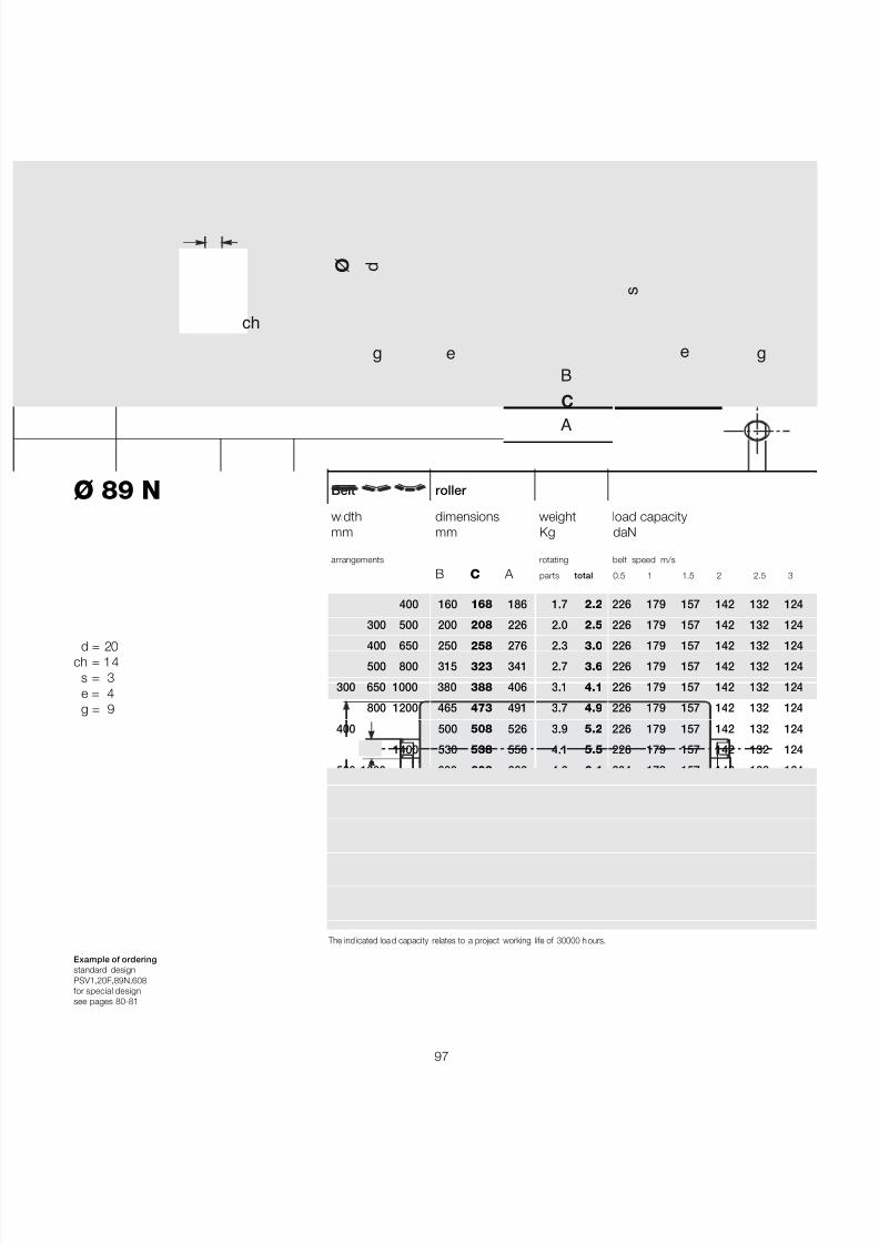
7/27/2019 31801183 Idler Roller
http://slidepdf.com/reader/full/31801183-idler-roller 99/308
97
Ø 89 N
Bearing 6204( 20 X 47 X 14 )
d = 20ch = 14
s = 3e = 4g = 9
Example of orderingstandard designPSV1,20F,89N,608for special designsee pages 80-81
Belt roller
width dimensions weight load capacitymm mm Kg daN
arrangements rotating belt speed m/s
B C A parts total 0.5 1 1.5 2 2.5 3
400 160 168 186 1.7 2.2 226 179 157 142 132 124
300 500 200 208 226 2.0 2.5 226 179 157 142 132 124
400 650 250 258 276 2.3 3.0 226 179 157 142 132 124
500 800 315 323 341 2.7 3.6 226 179 157 142 132 124
300 650 1000 380 388 406 3.1 4.1 226 179 157 142 132 124
800 1200 465 473 491 3.7 4.9 226 179 157 142 132 124
400 500 508 526 3.9 5.2 226 179 157 142 132 124
1400 530 538 556 4.1 5.5 226 179 157 142 132 124
500 1000 600 608 626 4.6 6.1 204 179 157 142 132 124
1200 700 708 726 5.2 7.0 173 173 157 142 132 124
650 750 758 776 5.5 7.4 161 161 157 142 132 124
1400 800 808 826 5.8 7.9 150 150 150 142 132 124
800 950 958 976 6.8 9.2 126 126 126 126 126 1241000 1150 1158 1176 8.1 11.0 104 104 104 104 104 104
1200 1400 1408 1426 9.7 13.2 85 85 85 85 85 85
1400 1600 1608 1626 11.0 15.0 75 75 75 75 75 75
The ind icated loa d capacity relates to a project working life of 30000 h ours.
B
A
ø
C
s
e e
ch
d
gg
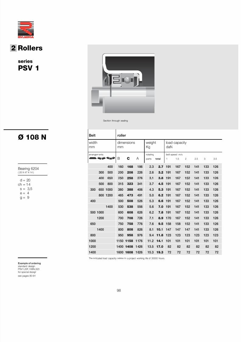
7/27/2019 31801183 Idler Roller
http://slidepdf.com/reader/full/31801183-idler-roller 100/308
98
®
2 Rollers
series
PSV 1
Ø 108 N
Bearing 6204( 20 X 47 X 14 )
d = 20ch = 14
s = 3,5e = 4g = 9
Example of orderingstandard designPSV1,20F,108N,323for special design
see pages 80-81
Section through sealing
Belt roller
width dimensions weight load capacitymm mm Kg daN
arrangements rotating belt speed m/s
B C A parts total 1 1.5 2 2.5 3 3.5
400 160 168 186 2.3 2.7 191 167 152 141 133 126
300 500 200 208 226 2.6 3.2 191 167 152 141 133 126
400 650 250 258 276 3.1 3.8 191 167 152 141 133 126
500 800 315 323 341 3.7 4.5 191 167 152 141 133 126
300 650 1000 380 388 406 4.3 5.3 191 167 152 141 133 126
800 1200 465 473 491 5.0 6.2 191 167 152 141 133 126
400 500 508 526 5.3 6.6 191 167 152 141 133 126
1400 530 538 556 5.6 7.0 191 167 152 141 133 126
500 1000 600 608 626 6.2 7.8 191 167 152 141 133 126
1200 700 708 726 7.1 8.9 170 167 152 141 133 126
650 750 758 776 7.6 9.5 158 158 152 141 133 126
1400 800 808 826 8.1 10.1 147 147 147 141 133 126
800 950 958 976 9.4 11.8 123 123 123 123 123 1231000 1150 1158 1176 11.2 14.1 101 101 101 101 101 101
1200 1400 1408 1426 13.5 17.0 82 82 82 82 82 82
1400 1600 1608 1626 15.3 19.3 72 72 72 72 72 72
The ind icated load capacity r elates to a project working life of 30000 hours.
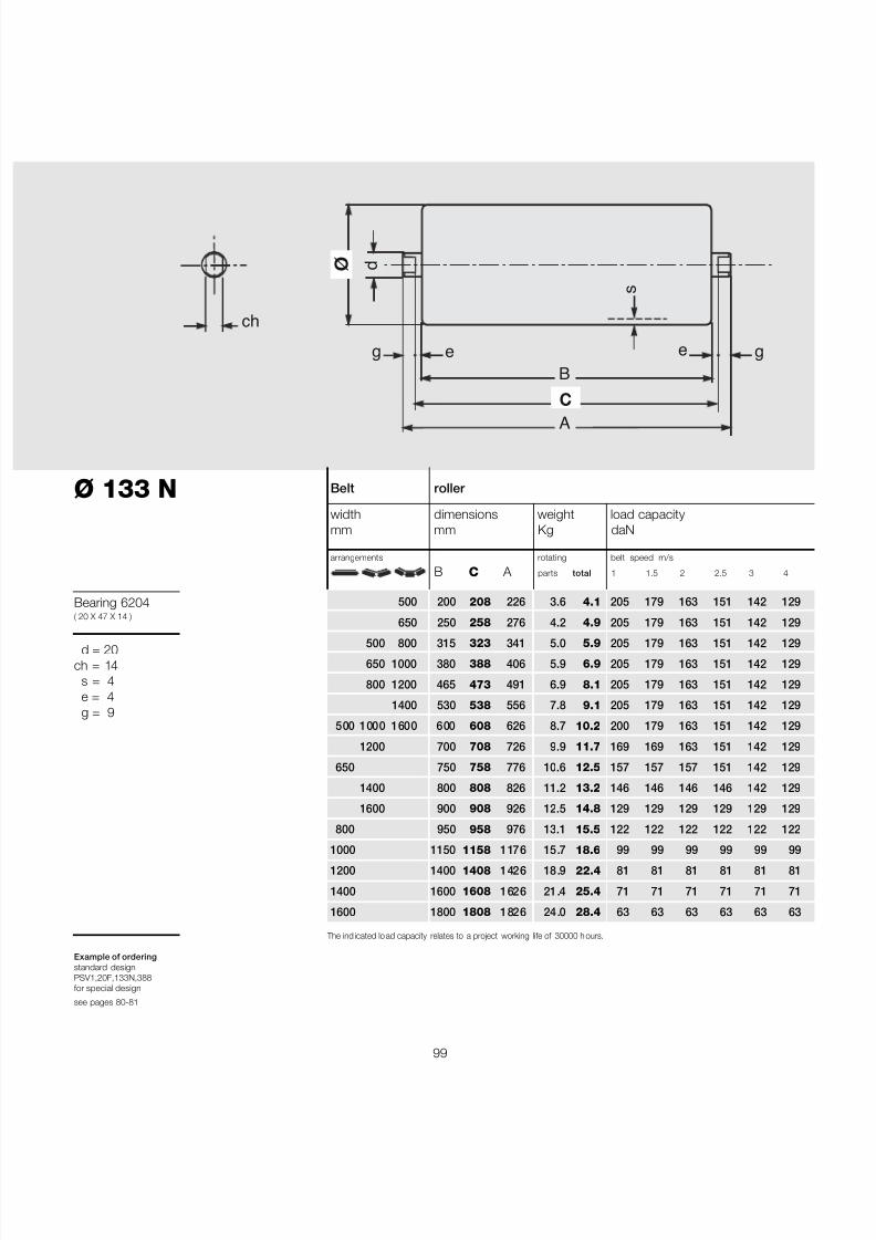
7/27/2019 31801183 Idler Roller
http://slidepdf.com/reader/full/31801183-idler-roller 101/308
99
Ø 133 N
Bearing 6204( 20 X 47 X 14 )
d = 20ch = 14
s = 4e = 4g = 9
Example of orderingstandard designPSV1,20F,133N,388for special design
see pages 80-81
Belt roller
width dimensions weight load capacitymm mm Kg daN
arrangements rotating belt speed m/s
B C A parts total 1 1.5 2 2.5 3 4
500 200 208 226 3.6 4.1 205 179 163 151 142 129
650 250 258 276 4.2 4.9 205 179 163 151 142 129
500 800 315 323 341 5.0 5.9 205 179 163 151 142 129
650 1000 380 388 406 5.9 6.9 205 179 163 151 142 129
800 1200 465 473 491 6.9 8.1 205 179 163 151 142 129
1400 530 538 556 7.8 9.1 205 179 163 151 142 129
500 1000 1600 600 608 626 8.7 10.2 200 179 163 151 142 129
1200 700 708 726 9.9 11.7 169 169 163 151 142 129
650 750 758 776 10.6 12.5 157 157 157 151 142 129
1400 800 808 826 11.2 13.2 146 146 146 146 142 129
1600 900 908 926 12.5 14.8 129 129 129 129 129 129
800 950 958 976 13.1 15.5 122 122 122 122 122 122
1000 1150 1158 1176 15.7 18.6 99 99 99 99 99 991200 1400 1408 1426 18.9 22.4 81 81 81 81 81 81
1400 1600 1608 1626 21.4 25.4 71 71 71 71 71 71
1600 1800 1808 1826 24.0 28.4 63 63 63 63 63 63
The ind icated lo ad capacity relates to a project working life of 30000 h ours.
B
A
ø
C
s
e e
ch
d
gg

7/27/2019 31801183 Idler Roller
http://slidepdf.com/reader/full/31801183-idler-roller 102/308
100
®
2 Rollers
series
PSV 2
Ø 89 N
Bearing 6205( 25 X 52 X 15 )
d = 25ch = 18
s = 3e = 4g = 12
Example of orderingstandard designPSV2,25F,89N,323for special design
see pages 80-81
Belt roller
width dimensions weight load capacitymm mm Kg daN
arrangements rotating belt speed m/s
B C A parts total 0.5 1 1.5 2 2.5 3
500 200 208 232 2.1 3.0 346 274 240 218 202 190
650 250 258 282 2.4 3.5 346 274 240 218 202 190
500 800 315 323 347 2.9 4.2 346 274 240 218 202 190
650 1000 380 388 412 3.3 4.9 346 274 240 218 202 190
800 1200 465 473 497 3.8 5.7 346 274 240 218 202 190
1400 530 538 562 4.2 6.4 346 274 240 218 202 190
500 1000 1600 600 608 632 4.7 7.1 346 274 240 218 202 190
1200 700 708 732 5.3 8.1 346 274 240 218 202 190
650 750 758 782 5.7 8.6 346 274 240 218 202 190
1400 800 808 832 6.0 9.2 346 274 240 218 202 190
1600 900 908 932 6.6 10.2 336 274 240 218 202 190
800 950 958 982 6.9 10.7 319 274 240 218 202 190
1000 1150 1158 1182 8.2 12.7 267 267 240 218 202 1901200 1400 1408 1432 9.8 15.3 224 224 224 218 202 190
1400 1600 1608 1632 11.1 17.4 201 201 201 201 201
1600 1800 1808 1832 12.4 19.4 183 183 183 183 183
The ind icated load capacity re lates to a project working life of 30000 hours.
Section through sealing
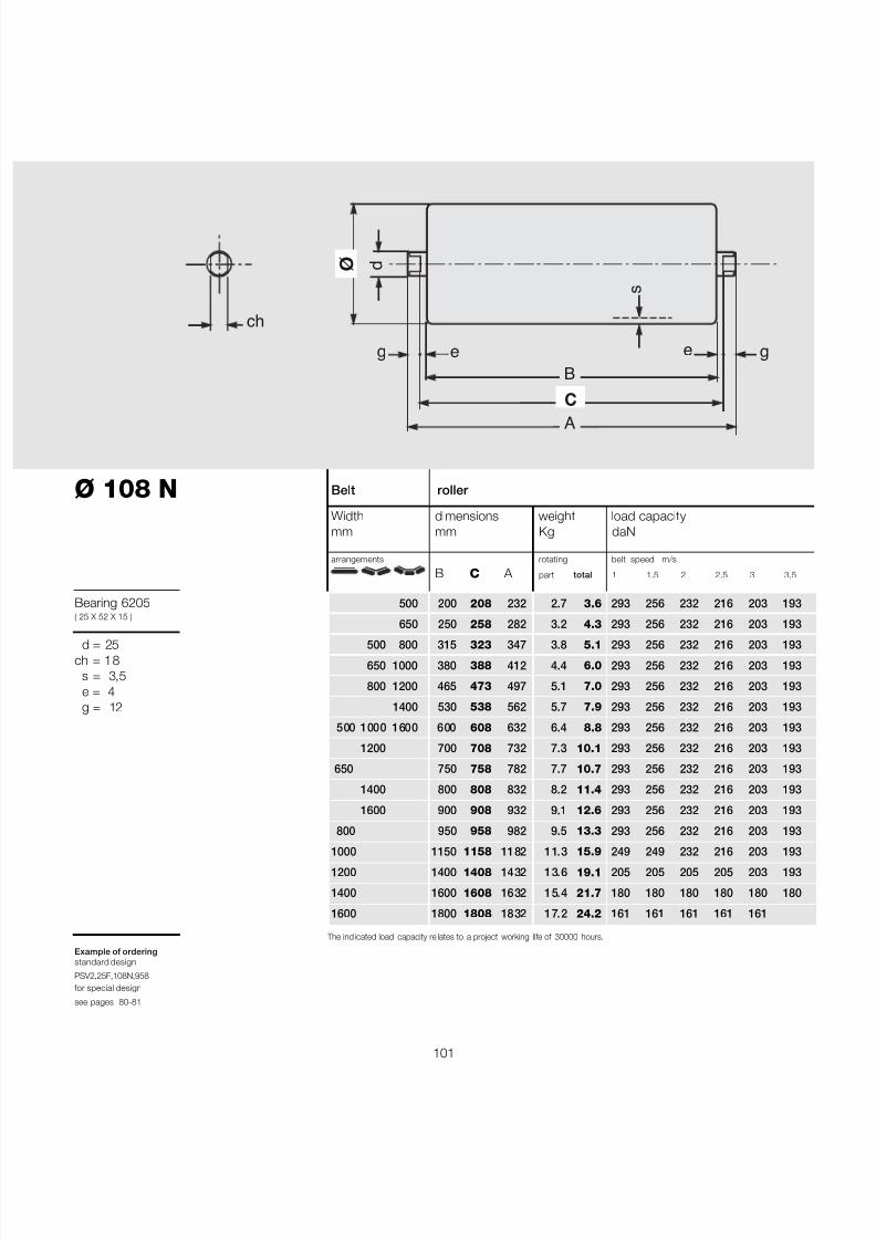
7/27/2019 31801183 Idler Roller
http://slidepdf.com/reader/full/31801183-idler-roller 103/308
101
Ø 108 N
Bearing 6205( 25 X 52 X 15 )
d = 25ch = 18
s = 3,5e = 4g = 12
Example of orderingstandard design
PSV2,25F,108N,958for special design
see pages 80-81
Belt roller
Width dimensions weight load capacitymm mm Kg daN
arrangements rotating belt speed m/s
B C A part total 1 1.5 2 2.5 3 3.5
500 200 208 232 2.7 3.6 293 256 232 216 203 193
650 250 258 282 3.2 4.3 293 256 232 216 203 193
500 800 315 323 347 3.8 5.1 293 256 232 216 203 193
650 1000 380 388 412 4.4 6.0 293 256 232 216 203 193
800 1200 465 473 497 5.1 7.0 293 256 232 216 203 193
1400 530 538 562 5.7 7.9 293 256 232 216 203 193
500 1000 1600 600 608 632 6.4 8.8 293 256 232 216 203 193
1200 700 708 732 7.3 10.1 293 256 232 216 203 193
650 750 758 782 7.7 10.7 293 256 232 216 203 193
1400 800 808 832 8.2 11.4 293 256 232 216 203 193
1600 900 908 932 9.1 12.6 293 256 232 216 203 193
800 950 958 982 9.5 13.3 293 256 232 216 203 193
1000 1150 1158 1182 11.3 15.9 249 249 232 216 203 1931200 1400 1408 1432 13.6 19.1 205 205 205 205 203 193
1400 1600 1608 1632 15.4 21.7 180 180 180 180 180 180
1600 1800 1808 1832 17.2 24.2 161 161 161 161 161
The ind icated load capacity re lates to a project working life of 30000 hours.
B
A
ø
C
s
e e
ch
d
gg

7/27/2019 31801183 Idler Roller
http://slidepdf.com/reader/full/31801183-idler-roller 104/308
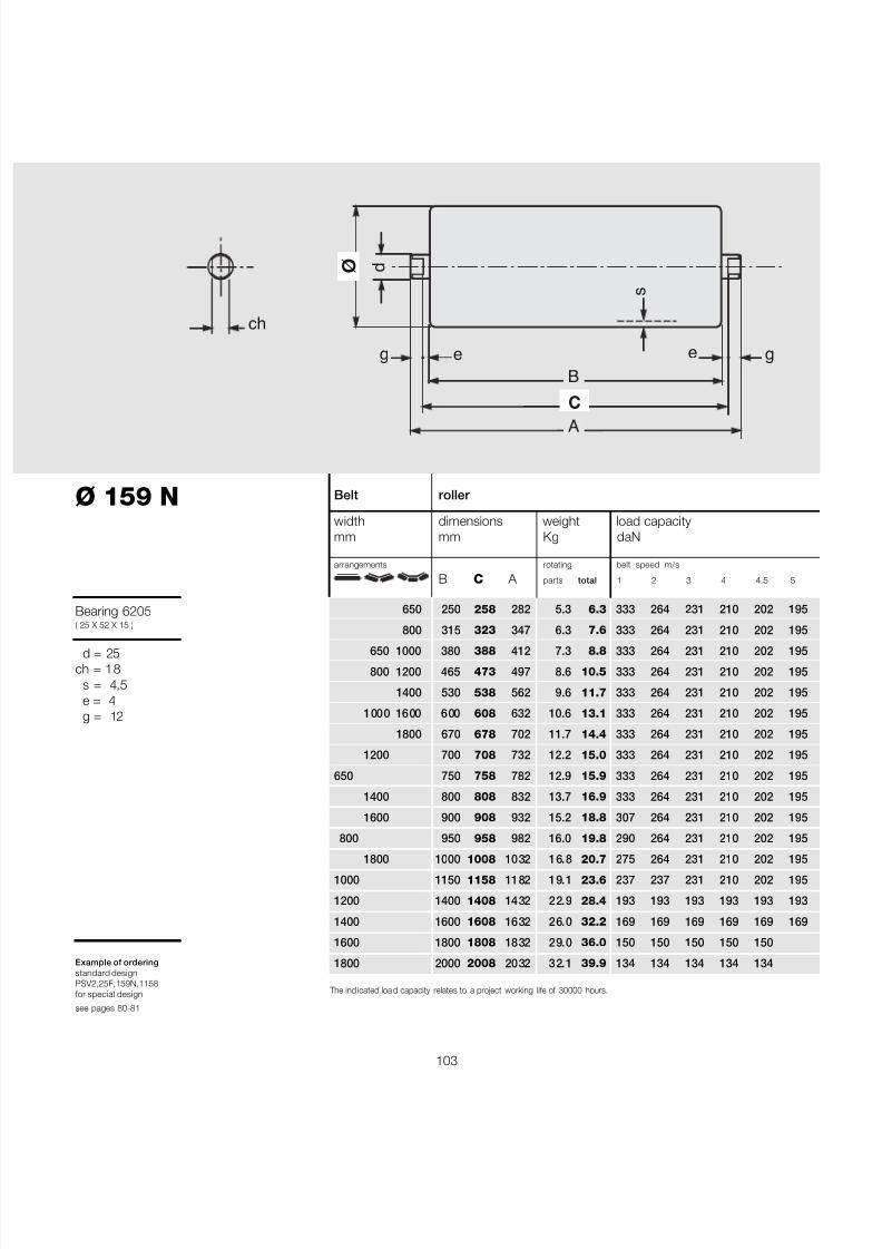
7/27/2019 31801183 Idler Roller
http://slidepdf.com/reader/full/31801183-idler-roller 105/308
103
Ø 159 N
Bearing 6205( 25 X 52 X 15 )
d = 25ch = 18
s = 4,5e = 4g = 12
Example of orderingstandard designPSV2,25F,159N,1158for special design
see pages 80-81
Belt roller
width dimensions weight load capacitymm mm Kg daN
arrangements rotating belt speed m/s
B C A parts total 1 2 3 4 4.5 5
650 250 258 282 5.3 6.3 333 264 231 210 202 195
800 315 323 347 6.3 7.6 333 264 231 210 202 195
650 1000 380 388 412 7.3 8.8 333 264 231 210 202 195
800 1200 465 473 497 8.6 10.5 333 264 231 210 202 195
1400 530 538 562 9.6 11.7 333 264 231 210 202 195
1000 1600 600 608 632 10.6 13.1 333 264 231 210 202 195
1800 670 678 702 11.7 14.4 333 264 231 210 202 195
1200 700 708 732 12.2 15.0 333 264 231 210 202 195
650 750 758 782 12.9 15.9 333 264 231 210 202 195
1400 800 808 832 13.7 16.9 333 264 231 210 202 195
1600 900 908 932 15.2 18.8 307 264 231 210 202 195
800 950 958 982 16.0 19.8 290 264 231 210 202 195
1800 1000 1008 1032 16.8 20.7 275 264 231 210 202 1951000 1150 1158 1182 19.1 23.6 237 237 231 210 202 195
1200 1400 1408 1432 22.9 28.4 193 193 193 193 193 193
1400 1600 1608 1632 26.0 32.2 169 169 169 169 169 169
1600 1800 1808 1832 29.0 36.0 150 150 150 150 150
1800 2000 2008 2032 32.1 39.9 134 134 134 134 134
The ind icated loa d capacity relates to a project working life of 30000 hours.
B
A
ø
C
s
e e
ch
d
gg

7/27/2019 31801183 Idler Roller
http://slidepdf.com/reader/full/31801183-idler-roller 106/308
104
®
2 Rollers
series
PSV 3
Ø 89 N
Bearing 6305( 25 X 62 X 17 )
d = 25ch = 18
s = 3e = 4g = 12
Example of orderingstandard designPSV3,25F,89N,323for special design
see pages 80-81
Belt roller
width dimensions weight load capacitymm mm Kg daN
arrangements rotating belt speed m/s
B C A parts total 0.5 1 1.5 2 2.5 3
650 250 258 282 2.8 3.9 509 404 353 321 298 280
800 315 323 347 3.2 4.5 509 404 353 321 298 280
650 1000 380 388 412 3.6 5.2 509 404 353 321 298 280
800 1200 465 473 497 4.2 6.1 509 404 353 321 298 280
1400 530 538 562 4.6 6.7 509 404 353 321 298 280
1000 1600 600 608 632 5.0 7.5 493 404 353 321 298 280
1200 700 708 732 5.7 8.5 420 404 353 321 298 280
650 750 758 782 6.0 9.0 392 392 353 321 298 280
1400 800 808 832 6.3 9.5 367 367 353 321 298 280
1600 900 908 932 7.0 10.5 327 327 327 321 298 280
800 950 958 982 7.3 11.1 310 310 310 310 298 280
1000 1150 1158 1182 8.6 13.1 259 259 259 259 259 259
1200 1400 1408 1432 10.2 15.7 218 218 218 218 218 2181400 1600 1608 1632 11.5 17.7 194 194 194 194 194 194
1600 1800 1808 1832 12.8 19.8 177 177 177 177 177 177
The ind icated load capacity re lates to a project working life of 30000 hours.
Section through sealing

7/27/2019 31801183 Idler Roller
http://slidepdf.com/reader/full/31801183-idler-roller 107/308
105
Ø 108 N
Bearing 6305( 25 X 62 X 17 )
d = 25ch = 18
s = 3,5e = 4g = 12
Example of orderingstandard designPSV3,25F,108N,958for special designsee pages 80-81
Belt roller
width dimensions weight load capacitymm mm Kg daN
arrangements rotating belt speed m/s
B C A parts total 1 1.5 2 2.5 3 3.5
650 250 258 282 3.6 4.7 431 376 342 317 299 284
800 315 323 347 4.2 5.5 431 376 342 317 299 284
650 1000 380 388 412 4.8 6.4 431 376 342 317 299 284
800 1200 465 473 497 5.5 7.5 431 376 342 317 299 284
1400 530 538 562 6.1 8.3 431 376 342 317 299 284
1000 1600 600 608 632 6.8 9.2 431 376 342 317 299 284
1200 700 708 732 7.7 10.5 404 376 342 317 299 284
650 750 758 782 8.1 11.1 375 375 342 317 299 284
1400 800 808 832 8.6 11.8 351 351 342 317 299 284
1600 900 908 932 9.5 13.0 310 310 310 310 299 284
800 950 958 982 9.9 13.7 294 294 294 294 294 284
1000 1150 1158 1182 11.7 16.3 242 242 242 242 242 242
1200 1400 1408 1432 14.0 19.5 199 199 199 199 199 1991400 1600 1608 1632 15.8 22.1 175 175 175 175 175 175
1600 1800 1808 1832 17.6 24.6 157 157 157 157 157
The ind icated loa d capacity relates to a project working life of 30000 hours.
B
A
ø
C
s
e e
ch
d
gg

7/27/2019 31801183 Idler Roller
http://slidepdf.com/reader/full/31801183-idler-roller 108/308

7/27/2019 31801183 Idler Roller
http://slidepdf.com/reader/full/31801183-idler-roller 109/308
107
Belt roller
width dimensions weight load capacitymm mm Kg daN
arrangements rotating belt speed m/s
B C A parts total 1 2 3 4 4.5 5
1000 380 388 412 7.8 9.4 490 389 340 309 297 287
1200 465 473 497 9.1 11.0 490 389 340 309 297 287
1400 530 538 562 10.1 12.3 490 389 340 309 297 287
1000 1600 600 608 632 11.2 13.6 467 389 340 309 297 287
1800 670 678 702 12.3 15.0 413 389 340 309 297 287
1200 700 708 732 12.7 15.5 393 389 340 309 297 287
2000 750 758 782 13.5 16.5 365 365 340 309 297 287
1400 800 808 832 14.3 17.4 340 340 340 309 297 287
1600 900 908 932 15.8 19.4 300 300 300 300 297 287
1800 1000 1008 1032 17.3 21.3 268 268 268 268 268 268
2000 1100 1108 1132 18.9 23.2 242 242 242 242 242 242
1000 1150 1158 1182 19.6 24.1 231 231 231 231 231 231
1200 1400 1408 1432 23.5 28.9 188 188 188 188 188 1881400 1600 1608 1632 26.5 32.8 164 164 164 164 164 164
1600 1800 1808 1832 29.6 36.6 146 146 146 146 146 146
1800 2000 2008 2032 32.6 40.4 131 131 131 131 131
2000 2200 2208 2232 35.7 44.3 119 119 119 119 119
Ø 159 N
Bearing 6305( 25 X 62 X 17 )
d = 25ch = 18
s = 4,5e = 4g = 12
Example of orderingstandard designPSV3,25F,159N,1158for special designsee pages 80-81
The ind icated load capacity re lates to a project working life of 30000 hours.
B
A
ø
C
s
e e
ch
d
gg
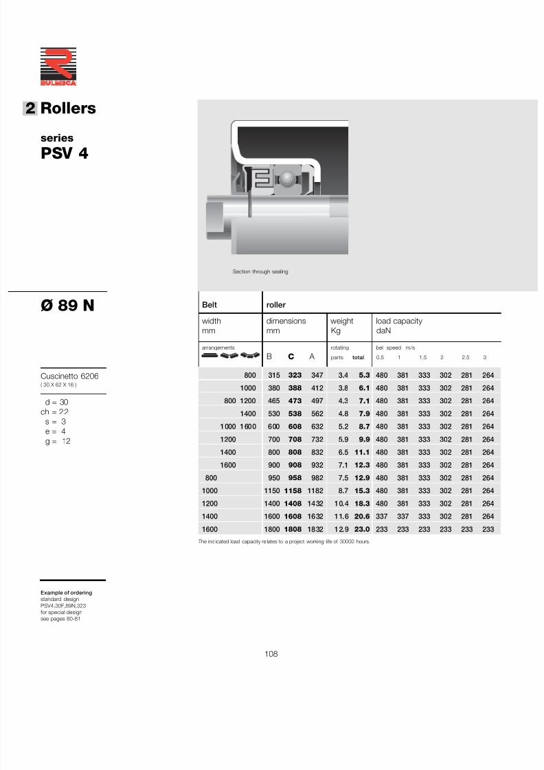
7/27/2019 31801183 Idler Roller
http://slidepdf.com/reader/full/31801183-idler-roller 110/308
108
®
2 Rollers
series
PSV 4
Ø 89 N
Cuscinetto 6206( 30 X 62 X 16 )
d = 30ch = 22
s = 3e = 4g = 12
Example of orderingstandard designPSV4,30F,89N,323for special designsee pages 80-81
Belt roller
width dimensions weight load capacitymm mm Kg daN
arrangements rotating bel speed m/s
B C A parts total 0.5 1 1.5 2 2.5 3
800 315 323 347 3.4 5.3 480 381 333 302 281 264
1000 380 388 412 3.8 6.1 480 381 333 302 281 264
800 1200 465 473 497 4.3 7.1 480 381 333 302 281 264
1400 530 538 562 4.8 7.9 480 381 333 302 281 264
1000 1600 600 608 632 5.2 8.7 480 381 333 302 281 264
1200 700 708 732 5.9 9.9 480 381 333 302 281 264
1400 800 808 832 6.5 11.1 480 381 333 302 281 264
1600 900 908 932 7.1 12.3 480 381 333 302 281 264
800 950 958 982 7.5 12.9 480 381 333 302 281 264
1000 1150 1158 1182 8.7 15.3 480 381 333 302 281 264
1200 1400 1408 1432 10.4 18.3 480 381 333 302 281 264
1400 1600 1608 1632 11.6 20.6 337 337 333 302 281 264
1600 1800 1808 1832 12.9 23.0 233 233 233 233 233 233 The ind icated load capacity re lates to a project working life of 30000 hours.
Section through sealing
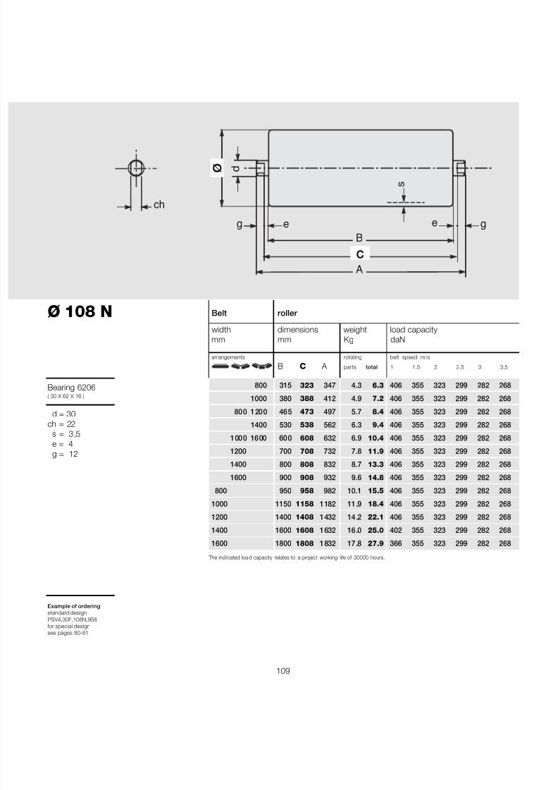
7/27/2019 31801183 Idler Roller
http://slidepdf.com/reader/full/31801183-idler-roller 111/308
109
Ø 108 N
Bearing 6206( 30 X 62 X 16 )
d = 30ch = 22
s = 3,5e = 4g = 12
Example of orderingstandard designPSV4,30F,108N,958for special designsee pages 80-81
The ind icated loa d capacity relates to a project working life of 30000 hours.
Belt roller
width dimensions weight load capacitymm mm Kg daN
arrangements rotating belt speed m/s
B C A parts total 1 1.5 2 2.5 3 3.5
800 315 323 347 4.3 6.3 406 355 323 299 282 268
1000 380 388 412 4.9 7.2 406 355 323 299 282 268
800 1200 465 473 497 5.7 8.4 406 355 323 299 282 268
1400 530 538 562 6.3 9.4 406 355 323 299 282 268
1000 1600 600 608 632 6.9 10.4 406 355 323 299 282 268
1200 700 708 732 7.8 11.9 406 355 323 299 282 268
1400 800 808 832 8.7 13.3 406 355 323 299 282 268
1600 900 908 932 9.6 14.8 406 355 323 299 282 268
800 950 958 982 10.1 15.5 406 355 323 299 282 268
1000 1150 1158 1182 11.9 18.4 406 355 323 299 282 268
1200 1400 1408 1432 14.2 22.1 406 355 323 299 282 268
1400 1600 1608 1632 16.0 25.0 402 355 323 299 282 268
1600 1800 1808 1832 17.8 27.9 366 355 323 299 282 268
B
A
ø
C
s
e e
ch
d
gg

7/27/2019 31801183 Idler Roller
http://slidepdf.com/reader/full/31801183-idler-roller 112/308
110
®
2 Rollers
series
PSV 4
Ø 133 N
Bearing 6206( 30 X 62 X 16 )
d = 30ch = 22
s = 4e = 4g = 12
Example of orderingstandard designPSV4,30F,133N,473for special designsee pages 80-81
Belt roller
width dimensions weight load capacitymm mm Kg daN
arrangements rotating belt speed m/s
B C A parts total 1 1.5 2 2.5 3 4
800 315 323 347 5.8 7.8 436 381 346 321 302 274
1000 380 388 412 6.7 8.9 436 381 346 321 302 274
800 1200 465 473 497 7.8 10.5 436 381 346 321 302 274
1400 530 538 562 8.6 11.7 436 381 346 321 302 274
1000 1600 600 608 632 9.5 13.0 436 381 346 321 302 274
1800 670 678 702 10.4 14.2 436 381 346 321 302 274
1200 700 708 732 10.8 14.8 436 381 346 321 302 274
2000 750 758 782 11.4 15.7 436 381 346 321 302 274
1400 800 808 832 12.0 16.6 436 381 346 321 302 274
1600 900 908 932 13.3 18.5 436 381 346 321 302 274
800 950 958 982 14.0 19.4 436 381 346 321 302 274
1800 1000 1008 1032 14.6 20.3 436 381 346 321 302 274
2000 1100 1108 1132 15.9 22.1 436 381 346 321 302 2741000 1150 1158 1182 16.5 23.0 436 381 346 321 302 274
1200 1400 1408 1432 19.7 27.6 412 381 346 321 302 274
1400 1600 1608 1632 22.3 31.3 363 363 346 321 302 274
1600 1800 1808 1832 24.8 34.9 324 324 324 321 302 274
1800 2000 2008 2032 27.4 38.6 294 294 294 294 294
2000 2200 2208 2232 29.9 42.2 270 270 270 270 270
The ind icated load capacity re lates to a project working life of 30000 hours.
Section through sealing
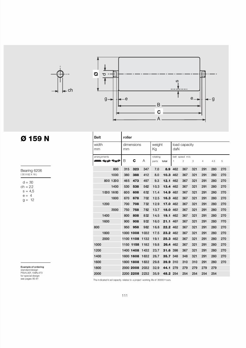
7/27/2019 31801183 Idler Roller
http://slidepdf.com/reader/full/31801183-idler-roller 113/308
111
Belt roller
width dimensions weight load capacitymm mm Kg daN
arrangements rotating belt speed m/s
B C A parts total 1 2 3 4 4.5 5
800 315 323 347 7.0 8.9 462 367 321 291 280 270
1000 380 388 412 8.0 10.3 462 367 321 291 280 270
800 1200 465 473 497 9.3 12.1 462 367 321 291 280 270
1400 530 538 562 10.3 13.4 462 367 321 291 280 270
1000 1600 600 608 632 11.4 14.9 462 367 321 291 280 270
1800 670 678 702 12.5 16.3 462 367 321 291 280 270
1200 700 708 732 12.9 17.0 462 367 321 291 280 270
2000 750 758 782 13.7 18.0 462 367 321 291 280 270
1400 800 808 832 14.5 19.1 462 367 321 291 280 270
1600 900 908 932 16.0 21.1 462 367 321 291 280 270
800 950 958 982 16.8 22.2 462 367 321 291 280 270
1800 1000 1008 1032 17.5 23.2 462 367 321 291 280 270
2000 1100 1108 1132 19.1 25.3 462 367 321 291 280 2701000 1150 1158 1182 19.8 26.4 462 367 321 291 280 270
1200 1400 1408 1432 23.7 31.6 398 367 321 291 280 270
1400 1600 1608 1632 26.7 35.7 348 348 321 291 280 270
1600 1800 1808 1832 29.8 39.9 310 310 310 291 280 270
1800 2000 2008 2032 32.9 44.1 279 279 279 279 279
2000 2200 2208 2232 35.9 48.2 254 254 254 254 254
The in dicated lo ad capacity relates to a project working life of 30000 h ours.
B
A
ø
C
s
e e
ch
d
gg
Ø 159 N
Bearing 6206( 30 X 62 X 16 )
d = 30ch = 22
s = 4,5e = 4g = 12
Example of orderingstandard designPSV4,30F,159N,473for special designsee pages 80-81
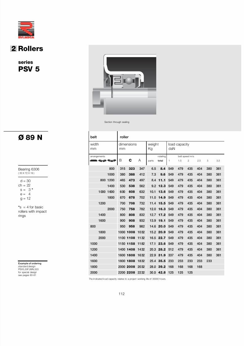
7/27/2019 31801183 Idler Roller
http://slidepdf.com/reader/full/31801183-idler-roller 114/308
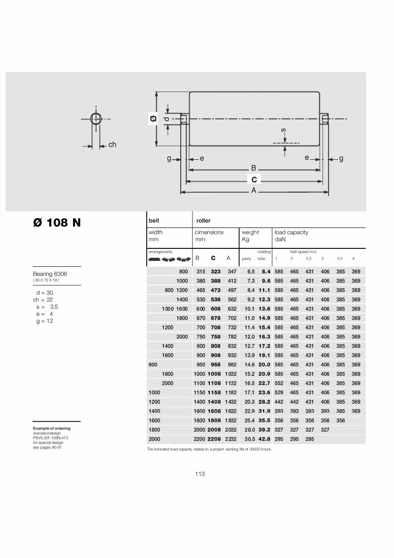
7/27/2019 31801183 Idler Roller
http://slidepdf.com/reader/full/31801183-idler-roller 115/308
113
belt roller
width dimensions weight load capacitymm mm Kg daN
arrangements rotating belt speed m/s
B C A parts total 1 2 2,5 3 3.5 4
800 315 323 347 6.5 8.4 585 465 431 406 385 369
1000 380 388 412 7.3 9.6 585 465 431 406 385 369
800 1200 465 473 497 8.4 11.1 585 465 431 406 385 369
1400 530 538 562 9.2 12.3 585 465 431 406 385 369
1000 1600 600 608 632 10.1 13.6 585 465 431 406 385 369
1800 670 678 702 11.0 14.9 585 465 431 406 385 369
1200 700 708 732 11.4 15.4 585 465 431 406 385 369
2000 750 758 782 12.0 16.3 585 465 431 406 385 369
1400 800 808 832 12.7 17.2 585 465 431 406 385 369
1600 900 908 932 13.9 19.1 585 465 431 406 385 369
800 950 958 982 14.6 20.0 585 465 431 406 385 369
1800 1000 1008 1032 15.2 20.9 585 465 431 406 385 369
2000 1100 1108 1132 16.5 22.7 552 465 431 406 385 3691000 1150 1158 1182 17.1 23.6 529 465 431 406 385 369
1200 1400 1408 1432 20.3 28.2 442 442 431 406 385 369
1400 1600 1608 1632 22.9 31.9 393 393 393 393 385 369
1600 1800 1808 1832 25.4 35.5 356 356 356 356 356
1800 2000 2008 2032 28.0 39.2 327 327 327 327
2000 2200 2208 2232 30.5 42.8 295 295 295
Ø 108 N
Bearing 6306( 30 X 72 X 19 )
d = 30ch = 22
s = 3,5e = 4g = 12
Example of orderingstandard designPSV5,30F,108N,473for special designsee pages 80-81
B
A
ø
C
s
e e
ch
d
gg
The ind icated lo ad capacity relates to a project working life of 30000 h ours.

7/27/2019 31801183 Idler Roller
http://slidepdf.com/reader/full/31801183-idler-roller 116/308
114
®
2 Rollers
series
PSV 5
Ø 133 N
Bearing 6306( 30 X 72 X 1`9 )
d = 30ch = 22
s = 4e = 4g = 12
Example of orderingstandard designPSV5,30F,133N,473for special designsee pages 80-81
Belt roller
width dimensions weight load capacitymm mm Kg daN
arrangements rotating belt speed m/s
B C A parts total 1 2 3 4 4.5 5
800 315 323 347 6.4 8.3 627 498 435 395 380 367
1000 380 388 412 7.2 9.5 627 498 435 395 380 367
800 1200 465 473 497 8.3 11.1 627 498 435 395 380 367
1400 530 538 562 9.2 12.3 627 498 435 395 380 367
1000 1600 600 608 632 10.1 13.5 627 498 435 395 380 367
1800 670 678 702 10.9 14.8 627 498 435 395 380 367
1200 700 708 732 11.3 15.4 627 498 435 395 380 367
2000 750 758 782 12.0 16.3 627 498 435 395 380 367
1400 800 808 832 12.6 17.2 627 498 435 395 380 367
1600 900 908 932 13.9 19.0 627 498 435 395 380 367
800 950 958 982 14.5 19.9 608 498 435 395 380 367
1800 1000 1008 1032 15.2 20.8 577 498 435 395 380 367
2000 1100 1108 1132 16.4 22.7 524 498 435 395 380 3671000 1150 1158 1182 17.1 23.6 501 498 435 395 380 367
1200 1400 1408 1432 20.3 28.2 412 412 412 395 380 367
1400 1600 1608 1632 22.8 31.8 363 363 363 363 363 363
1600 1800 1808 1832 25.4 35.5 324 324 324 324 324
1800 2000 2008 2032 27.9 39.1 294 294 294 294 294
2000 2200 2208 2232 30.5 42.8 270 270 270 270 270
The ind icated load capacity re lates to a project working life of 30000 hours.
Section through sealing
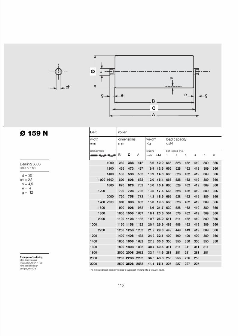
7/27/2019 31801183 Idler Roller
http://slidepdf.com/reader/full/31801183-idler-roller 117/308
115
Belt roller
width dimensions weight load capacitymm mm Kg daN
arrangements rotating belt speed m/s
B C A parts total 1 2 3 4 5 6
1000 380 388 412 8.6 10.9 666 528 462 419 389 366
1200 465 473 497 9.9 12.6 666 528 462 419 389 366
1400 530 538 562 10.9 14.0 666 528 462 419 389 366
1000 1600 600 608 632 12.0 15.4 666 528 462 419 389 366
1800 670 678 702 13.0 16.9 666 528 462 419 389 366
1200 700 708 732 13.5 17.5 666 528 462 419 389 366
2000 750 758 782 14.3 18.6 666 528 462 419 389 366
1400 2200 800 808 832 15.0 19.6 666 528 462 419 389 366
1600 900 908 932 16.6 21.7 630 528 462 419 389 366
1800 1000 1008 1032 18.1 23.8 564 528 462 419 389 366
2000 1100 1108 1132 19.6 25.9 511 511 462 419 389 366
1000 1150 1158 1182 20.4 26.9 488 488 462 419 389 366
2200 1250 1258 1282 21.9 29.0 449 449 449 419 389 3661200 1400 1408 1432 24.2 32.1 400 400 400 400 389 366
1400 1600 1608 1632 27.3 36.3 350 350 350 350 350 350
1600 1800 1808 1832 30.4 40.5 311 311 311 311 311
1800 2000 2008 2032 33.4 44.6 281 281 281 281 281
2000 2200 2208 2232 36.5 48.8 256 256 256 256
2200 2500 2508 2532 41.1 55.1 227 227 227 227
The ind icated load capacity re lates to a project working life of 30000 hours.
B
A
ø
C
s
e e
ch
d
gg
Ø 159 N
Bearing 6306( 30 X 72 X 19 )
d = 30ch = 22
s = 4,5e = 4g = 12
Example of orderingstandard designPSV5,30F,159N,1158for special designsee pages 80-81
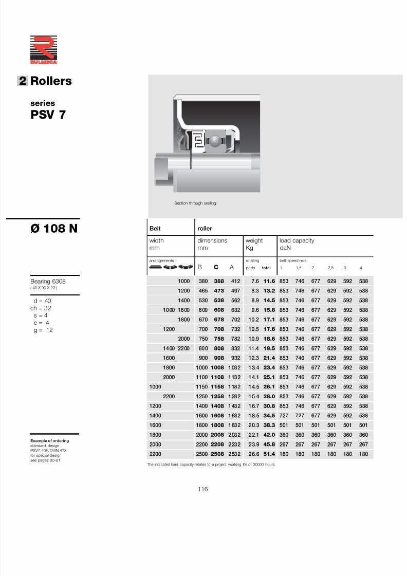
7/27/2019 31801183 Idler Roller
http://slidepdf.com/reader/full/31801183-idler-roller 118/308
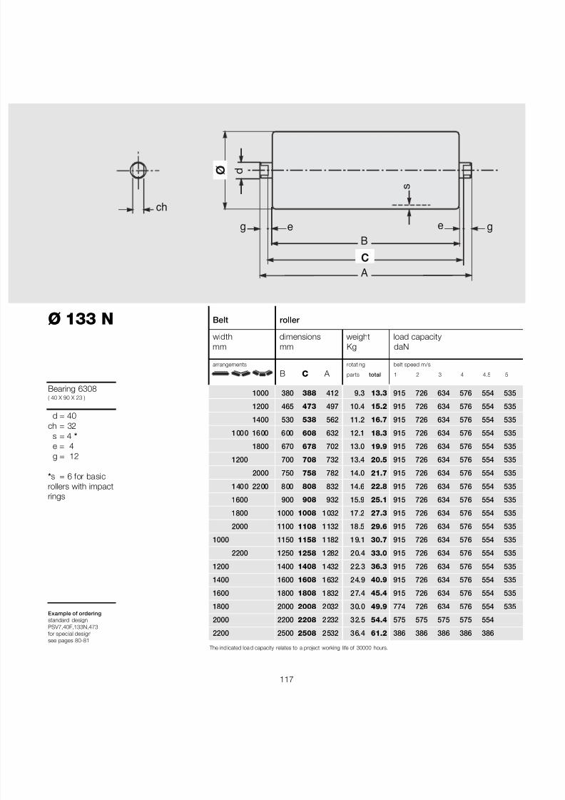
7/27/2019 31801183 Idler Roller
http://slidepdf.com/reader/full/31801183-idler-roller 119/308
117
Ø 133 N
Bearing 6308( 40 X 90 X 23 )
d = 40ch = 32
s = 4 *e = 4g = 12
*s = 6 for basicrollers with impactrings
Example of orderingstandard designPSV7,40F,133N,473for special designsee pages 80-81
B
A
ø
C
s
e e
ch
d
gg
Belt roller
width dimensions weight load capacitymm mm Kg daN
arrangements rotating belt speed m/s
B C A parts total 1 2 3 4 4.5 5
1000 380 388 412 9.3 13.3 915 726 634 576 554 535
1200 465 473 497 10.4 15.2 915 726 634 576 554 535
1400 530 538 562 11.2 16.7 915 726 634 576 554 535
1000 1600 600 608 632 12.1 18.3 915 726 634 576 554 535
1800 670 678 702 13.0 19.9 915 726 634 576 554 535
1200 700 708 732 13.4 20.5 915 726 634 576 554 535
2000 750 758 782 14.0 21.7 915 726 634 576 554 535
1400 2200 800 808 832 14.6 22.8 915 726 634 576 554 535
1600 900 908 932 15.9 25.1 915 726 634 576 554 535
1800 1000 1008 1032 17.2 27.3 915 726 634 576 554 535
2000 1100 1108 1132 18.5 29.6 915 726 634 576 554 535
1000 1150 1158 1182 19.1 30.7 915 726 634 576 554 535
2200 1250 1258 1282 20.4 33.0 915 726 634 576 554 535
1200 1400 1408 1432 22.3 36.3 915 726 634 576 554 535
1400 1600 1608 1632 24.9 40.9 915 726 634 576 554 535
1600 1800 1808 1832 27.4 45.4 915 726 634 576 554 535
1800 2000 2008 2032 30.0 49.9 774 726 634 576 554 535
2000 2200 2208 2232 32.5 54.4 575 575 575 575 554
2200 2500 2508 2532 36.4 61.2 386 386 386 386 386
The ind icated loa d capacity relates to a project working life of 30000 hours.

7/27/2019 31801183 Idler Roller
http://slidepdf.com/reader/full/31801183-idler-roller 120/308
118
®
2 Rollers
series
PSV 7
Ø 159 N
Bearing 6308(40 X 90 X 23 )
d = 40ch = 32
s = 4,5e = 4g = 12
Example of orderingstandard designPSV7,40F,159N,1158for special designsee pages 80-81
Section through sealing
Belt roller
width dimensions weight load capacitymm mm Kg daN
arrangements rotating belt speed m/s
B C A parts total 1 2 3 4 5 6
1000 380 388 412 10.6 14.7 971 771 673 612 568 534
1200 465 473 497 11.9 16.8 971 771 673 612 568 534
1400 530 538 562 12.9 18.4 971 771 673 612 568 534
1000 1600 600 608 632 14.0 20.2 971 771 673 612 568 534
1800 670 678 702 15.1 22.0 971 771 673 612 568 534
1200 700 708 732 15.5 22.7 971 771 673 612 568 534
2000 750 758 782 16.3 24.0 971 771 673 612 568 534
1400 2200 800 808 832 17.1 25.2 971 771 673 612 568 534
1600 900 908 932 18.6 27.7 971 771 673 612 568 534
1800 1000 1008 1032 20.1 30.3 971 771 673 612 568 534
2000 1100 1108 1132 21.7 32.8 971 771 673 612 568 534
1000 1150 1158 1182 22.4 34.0 971 771 673 612 568 534
2200 1250 1258 1282 24.0 36.6 971 771 673 612 568 5341200 1400 1408 1432 26.3 40.3 971 771 673 612 568 534
1400 1600 1608 1632 29.4 45.4 971 771 673 612 568 534
1600 1800 1808 1832 32.4 50.4 898 771 673 612 568
1800 2000 2008 2032 35.5 55.4 819 771 673 612 568
2000 2200 2208 2232 38.6 60.5 755 755 673 612
2200 2500 2508 2532 43.2 68.0 670 670 670 612
The ind icated loa d capacity relates to a project working life of 30000 h ours.
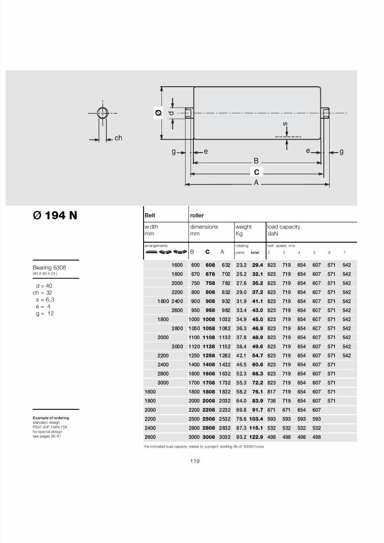
7/27/2019 31801183 Idler Roller
http://slidepdf.com/reader/full/31801183-idler-roller 121/308
119
B
A
ø
C
s
e e
ch
d
gg
The ind icated lo ad capacity relates to a project working life of 30000 h ours.
Belt roller
width dimensions weight load capacitymm mm Kg daN
arrangements rotating belt speed m/s
B C A parts total 2 3 4 5 6 7
1600 600 608 632 23.2 29.4 823 719 654 607 571 542
1800 670 678 702 25.2 32.1 823 719 654 607 571 542
2000 750 758 782 27.6 35.2 823 719 654 607 571 542
2200 800 808 832 29.0 37.2 823 719 654 607 571 542
1600 2400 900 908 932 31.9 41.1 823 719 654 607 571 542
2600 950 958 982 33.4 43.0 823 719 654 607 571 542
1800 1000 1008 1032 34.9 45.0 823 719 654 607 571 542
2800 1050 1058 1082 36.3 46.9 823 719 654 607 571 542
2000 1100 1108 1132 37.8 48.9 823 719 654 607 571 542
3000 1120 1128 1152 38.4 49.6 823 719 654 607 571 542
2200 1250 1258 1282 42.1 54.7 823 719 654 607 571 542
2400 1400 1408 1432 46.5 60.6 823 719 654 607 571
2800 1600 1608 1632 52.3 68.3 823 719 654 607 5713000 1700 1708 1732 55.3 72.2 823 719 654 607 571
1600 1800 1808 1832 58.2 76.1 817 719 654 607 571
1800 2000 2008 2032 64.0 83.9 736 719 654 607 571
2000 2200 2208 2232 69.8 91.7 671 671 654 607
2200 2500 2508 2532 78.6 103.4 593 593 593 593
2400 2800 2808 2832 87.3 115.1 532 532 532 532
2600 3000 3008 3032 93.2 122.9 498 498 498 498
Ø 194 N
Bearing 6308(40 X 90 X 23 )
d = 40ch = 32
s = 6,3e = 4g = 12
Example of orderingstandard designPSV7,40F,194N,758for special designsee pages 80-81
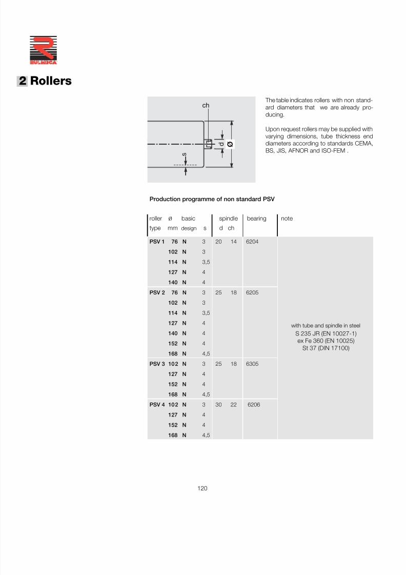
7/27/2019 31801183 Idler Roller
http://slidepdf.com/reader/full/31801183-idler-roller 122/308
120
®
2 Rollers
Production programme of non standard PSV
roller ø basic spindle bearing note
type mm design s d ch
PSV 1 76 N 3 20 14 6204
102 N 3
114 N 3,5
127 N 4
140 N 4
PSV 2 76 N 3 25 18 6205
102 N 3
114 N 3,5
127 N 4
140 N 4
152 N 4
168 N 4,5
PSV 3 102 N 3 25 18 6305
127 N 4
152 N 4
168 N 4,5PSV 4 102 N 3 30 22 6206
127 N 4
152 N 4
168 N 4,5
ø d
s
ch The table indicates rollers with non stand-ard diameters that we are already pro-ducing.
Upon request rollers may be supplied withvarying dimensions, tube thickness enddiameters according to standards CEMA,BS, JIS, AFNOR and ISO-FEM .
with tube and spindle in steelS 235 JR (EN 10027-1)ex Fe 360 (EN 10025)
St 37 (DIN 17100)
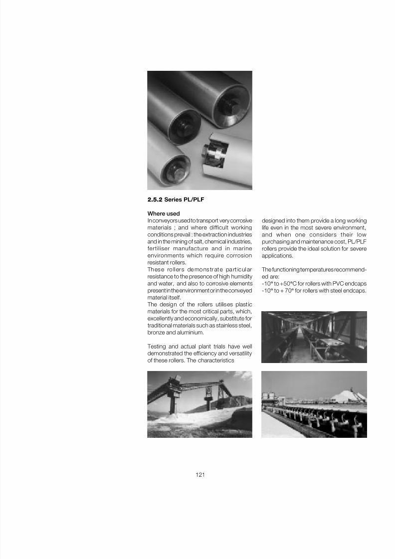
7/27/2019 31801183 Idler Roller
http://slidepdf.com/reader/full/31801183-idler-roller 123/308
121
2.5.2 Series PL/PLF
Where usedIn conveyors used to transport very corrosivematerials ; and where difficult workingconditions prevail : the extraction industriesand in the mining of salt, chemical industries,fertiliser manufacture and in marineenvironments which require corrosionresistant rollers.
These ro ll ers de mo ns tr at e pa rt icul arresistance to the presence of high humidityand water, and also to corrosive elementspresent in the environment or in the conveyedmaterial itself.
The design of the rollers utilises plast icmaterials for the most critical parts, which,excellently and economically, substitute fortraditional materials such as stainless steel,bronze and aluminium.
Testing and actual plant trials have welldemonstrated the efficiency and versatilityof these rollers. The characteristics
designed into them provide a long workinglife even in the most severe environment,and when one considers their lowpurchasing and maintenance cost, PL/PLFrollers provide the ideal solution for severeapplications.
The functioning temperatures recommend-ed are:-10 ° to +50 ° C for rollers with PVC endcaps-10 ° to + 70 ° for rollers with steel endcaps.
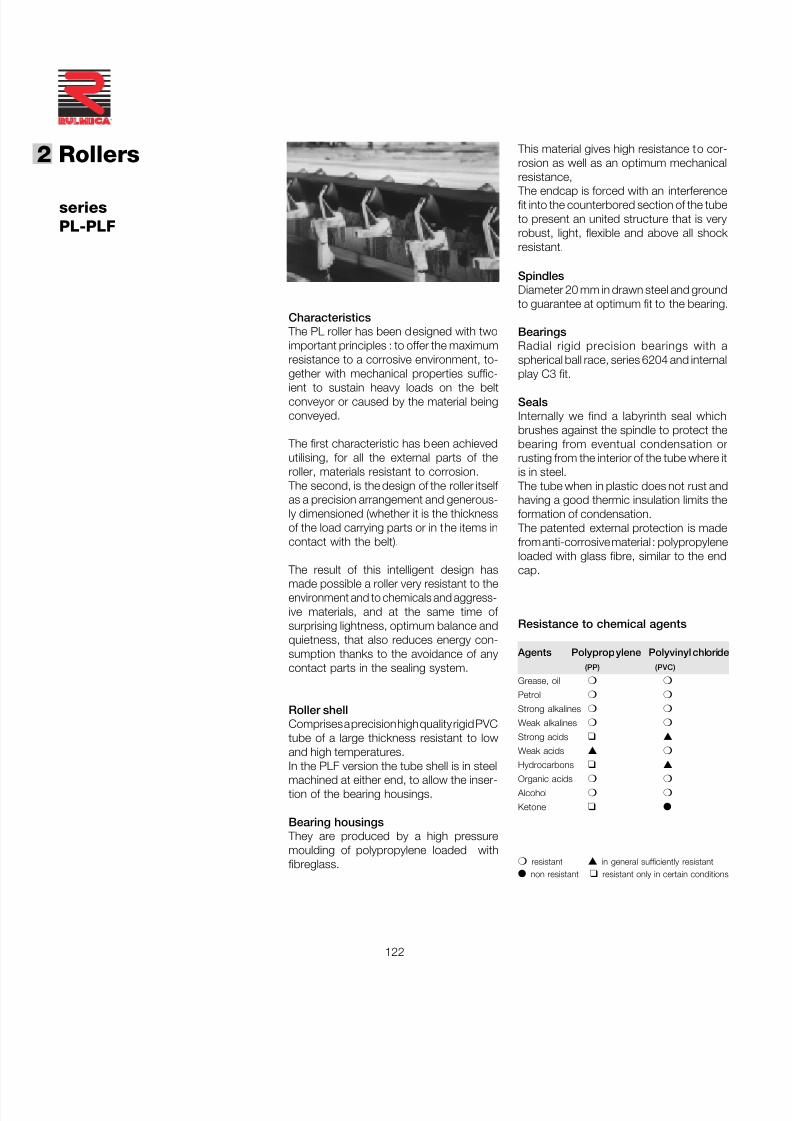
7/27/2019 31801183 Idler Roller
http://slidepdf.com/reader/full/31801183-idler-roller 124/308
122
®
2 Rollers
Characteristics The PL roller has been designed with twoimportant principles : to offer the maximumresistance to a corrosive environment, to-gether with mechanical properties suffic-ient to sustain heavy loads on the beltconveyor or caused by the material beingconveyed.
The first characteristic has been achievedutilising, for all the external parts of theroller, materials resistant to corrosion.
The second, is the design of the roller itself as a precision arrangement and generous-ly dimensioned (whether it is the thicknessof the load carrying parts or in the items incontact with the belt).
The result of this intelligent design hasmade possible a roller very resistant to theenvironment and to chemicals and aggress-ive materials, and at the same time of surprising lightness, optimum balance andquietness, that also reduces energy con-sumption thanks to the avoidance of anycontact parts in the sealing system.
Roller shellComprises a precision high quality rigid PVCtube of a large thickness resistant to lowand high temperatures.
In the PLF version the tube shell is in steelmachined at either end, to allow the inser-tion of the bearing housings.
Bearing housings They are produced by a high pressuremoulding of polypropylene loaded withfibreglass.
seriesPL-PLF
Resistance to chemical agents
Agents Polypropylene Polyvinyl chloride(PP) (PVC)
Grease, oil ❍ ❍
Petrol ❍ ❍
Strong alkalines ❍ ❍
Weak alkalines ❍ ❍
Strong acids ❑ ▲
Weak acids ▲ ❍
Hydrocarbons ❑ ▲
Organic acids ❍ ❍
Alcohol ❍ ❍
Ketone ❑ ●
❍ resistant ▲ in general sufficiently resistant● non resistant ❑ resistant only in certain conditions
SpindlesDiameter 20 mm in drawn steel and groundto guarantee at optimum fit to the bearing.
BearingsRadial rigid precision bearings with aspherical ball race, series 6204 and internalplay C3 fit.
SealsInternally we find a labyrinth seal whichbrushes against the spindle to protect thebearing from eventual condensation orrusting from the interior of the tube where itis in steel.
The tube when in plastic does not rust andhaving a good thermic insulation limits theformation of condensation.
The patented external protection is madefrom anti-corrosive material : polypropyleneloaded with glass fibre, similar to the endcap.
This material gives high resistance to cor-rosion as well as an optimum mechanicalresistance,
The endcap is forced with an interferencefit into the counterbored section of the tubeto present an united structure that is veryrobust, light, flexible and above all shock resistant.
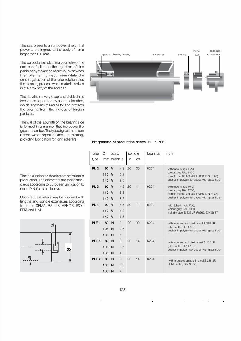
7/27/2019 31801183 Idler Roller
http://slidepdf.com/reader/full/31801183-idler-roller 125/308
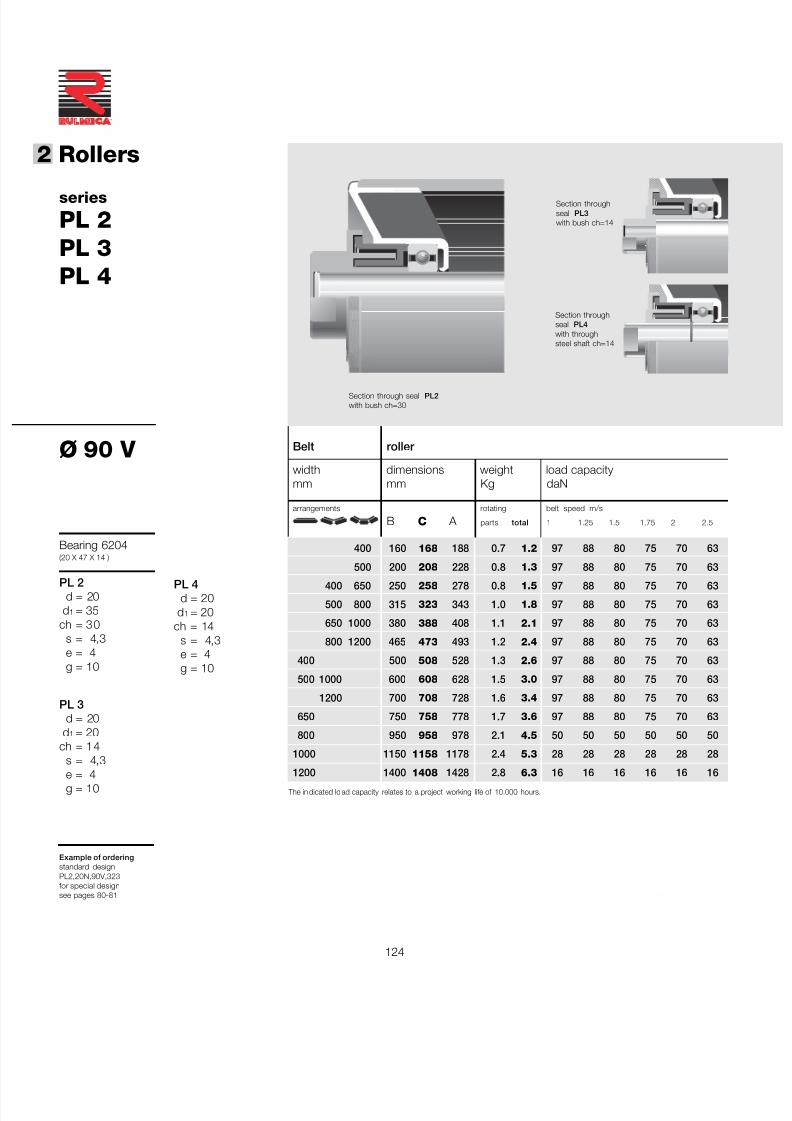
7/27/2019 31801183 Idler Roller
http://slidepdf.com/reader/full/31801183-idler-roller 126/308
124
®
2 Rollers
a richiesta
The in dicated lo ad capacity relates to a project working life of 10.000 hours.
series
PL 2PL 3PL 4
Ø 90 V
Bearing 6204(20 X 47 X 14 )
PL 2d = 20
d 1 = 35ch = 30
s = 4,3e = 4g = 10
PL 3d = 20
d 1 = 20ch = 14
s = 4,3e = 4g = 10
Example of orderingstandard designPL2,20N,90V,323for special designsee pages 80-81
Section through seal PL2with bush ch=30
Section throughseal PL4with throughsteel shaft ch=14
Belt roller
width dimensions weight load capacitymm mm Kg daN
arrangements rotating belt speed m/s
B C A parts total 1 1.25 1.5 1.75 2 2.5
400 160 168 188 0.7 1.2 97 88 80 75 70 63
500 200 208 228 0.8 1.3 97 88 80 75 70 63
400 650 250 258 278 0.8 1.5 97 88 80 75 70 63
500 800 315 323 343 1.0 1.8 97 88 80 75 70 63
650 1000 380 388 408 1.1 2.1 97 88 80 75 70 63
800 1200 465 473 493 1.2 2.4 97 88 80 75 70 63
400 500 508 528 1.3 2.6 97 88 80 75 70 63
500 1000 600 608 628 1.5 3.0 97 88 80 75 70 63
1200 700 708 728 1.6 3.4 97 88 80 75 70 63
650 750 758 778 1.7 3.6 97 88 80 75 70 63
800 950 958 978 2.1 4.5 50 50 50 50 50 50
1000 1150 1158 1178 2.4 5.3 28 28 28 28 28 28
1200 1400 1408 1428 2.8 6.3 16 16 16 16 16 16
PL 4d = 20
d 1 = 20ch = 14
s = 4,3e = 4g = 10
Section throughseal PL3with bush ch=14
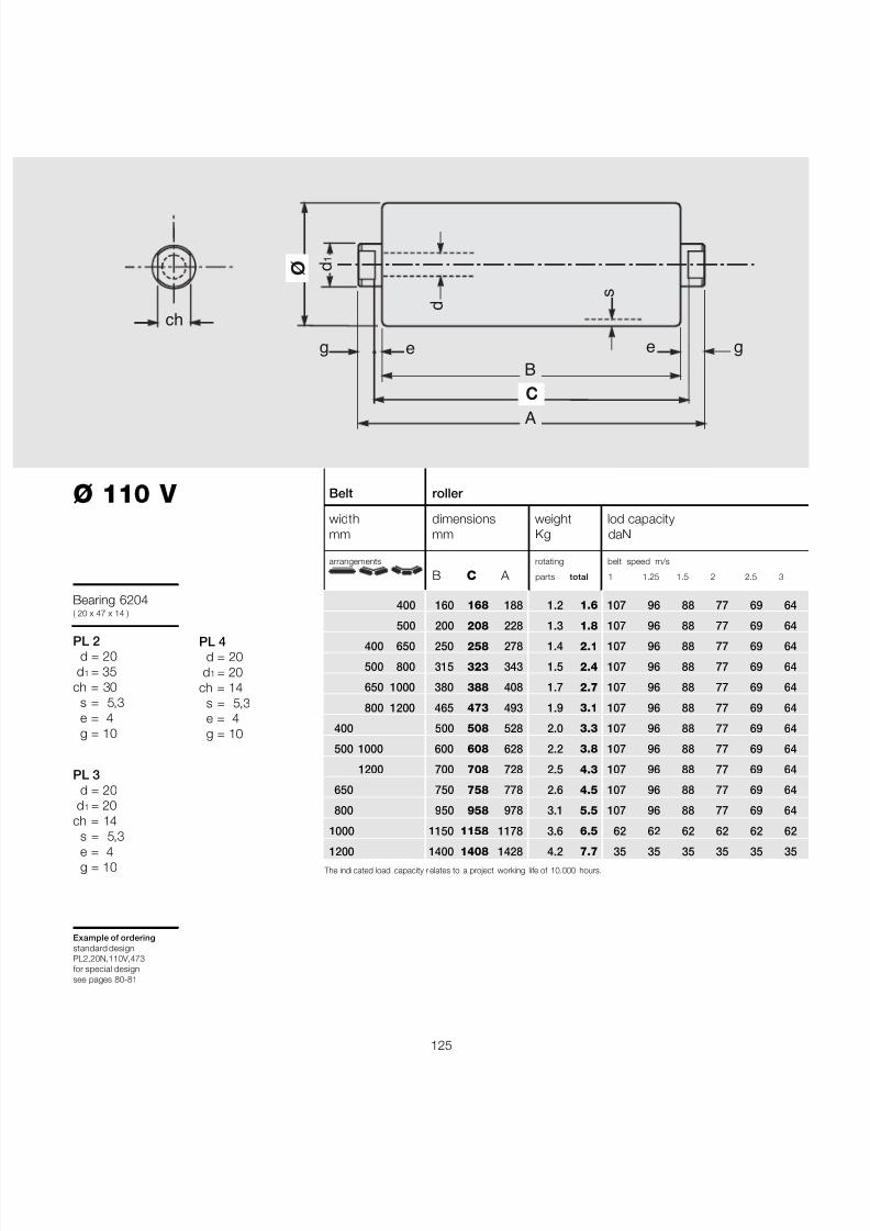
7/27/2019 31801183 Idler Roller
http://slidepdf.com/reader/full/31801183-idler-roller 127/308
125
Ø 110 V
Bearing 6204( 20 x 47 x 14 )
PL 2d = 20
d 1 = 35ch = 30
s = 5,3e = 4g = 10
PL 3d = 20
d 1 = 20ch = 14
s = 5,3e = 4g = 10
Example of orderingstandard designPL2,20N,110V,473for special designsee pages 80-81
Belt roller
width dimensions weight lod capacitymm mm Kg daN
arrangements rotating belt speed m/s
B C A parts total 1 1.25 1.5 2 2.5 3
400 160 168 188 1.2 1.6 107 96 88 77 69 64
500 200 208 228 1.3 1.8 107 96 88 77 69 64
400 650 250 258 278 1.4 2.1 107 96 88 77 69 64
500 800 315 323 343 1.5 2.4 107 96 88 77 69 64
650 1000 380 388 408 1.7 2.7 107 96 88 77 69 64
800 1200 465 473 493 1.9 3.1 107 96 88 77 69 64
400 500 508 528 2.0 3.3 107 96 88 77 69 64
500 1000 600 608 628 2.2 3.8 107 96 88 77 69 64
1200 700 708 728 2.5 4.3 107 96 88 77 69 64
650 750 758 778 2.6 4.5 107 96 88 77 69 64
800 950 958 978 3.1 5.5 107 96 88 77 69 64
1000 1150 1158 1178 3.6 6.5 62 62 62 62 62 62
1200 1400 1408 1428 4.2 7.7 35 35 35 35 35 35 The indi cated load capacity r elates to a project working life of 10.000 hours.
B
A
ø
C
s
e e
d
d 1
ch
g g
PL 4d = 20
d 1 = 20ch = 14
s = 5,3e = 4g = 10

7/27/2019 31801183 Idler Roller
http://slidepdf.com/reader/full/31801183-idler-roller 128/308
7/27/2019 31801183 Idler Roller
http://slidepdf.com/reader/full/31801183-idler-roller 129/308
127
B
A
ø
C
s
e e
d
d 1
ch
g g
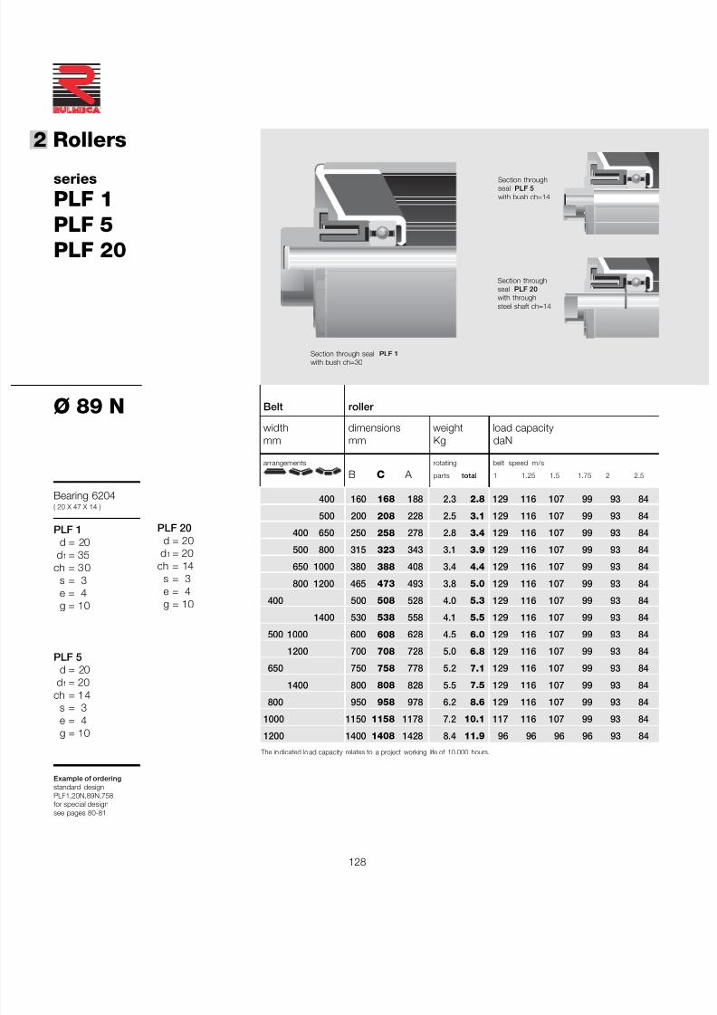
7/27/2019 31801183 Idler Roller
http://slidepdf.com/reader/full/31801183-idler-roller 130/308
128
®
2 Rollers
The in dicated lo ad capacity relates to a project working life of 10.000 hours.
Belt roller
width dimensions weight load capacitymm mm Kg daN
arrangements rotating belt speed m/s
B C A parts total 1 1.25 1.5 1.75 2 2.5
400 160 168 188 2.3 2.8 129 116 107 99 93 84
500 200 208 228 2.5 3.1 129 116 107 99 93 84
400 650 250 258 278 2.8 3.4 129 116 107 99 93 84
500 800 315 323 343 3.1 3.9 129 116 107 99 93 84
650 1000 380 388 408 3.4 4.4 129 116 107 99 93 84
800 1200 465 473 493 3.8 5.0 129 116 107 99 93 84
400 500 508 528 4.0 5.3 129 116 107 99 93 84
1400 530 538 558 4.1 5.5 129 116 107 99 93 84
500 1000 600 608 628 4.5 6.0 129 116 107 99 93 84
1200 700 708 728 5.0 6.8 129 116 107 99 93 84
650 750 758 778 5.2 7.1 129 116 107 99 93 84
1400 800 808 828 5.5 7.5 129 116 107 99 93 84
800 950 958 978 6.2 8.6 129 116 107 99 93 84
1000 1150 1158 1178 7.2 10.1 117 116 107 99 93 84
1200 1400 1408 1428 8.4 11.9 96 96 96 96 93 84
series
PLF 1PLF 5PLF 20
Ø 89 N
Bearing 6204( 20 X 47 X 14 )
PLF 1d = 20
d 1 = 35ch = 30
s = 3e = 4g = 10
PLF 5d = 20
d 1 = 20
ch = 14s = 3e = 4g = 10
Example of orderingstandard designPLF1,20N,89N,758for special designsee pages 80-81
PLF 20d = 20
d 1 = 20ch = 14
s = 3e = 4g = 10
Section through seal PLF 1with bush ch=30
Section throughseal PLF 20with throughsteel shaft ch=14
Section throughseal PLF 5with bush ch=14
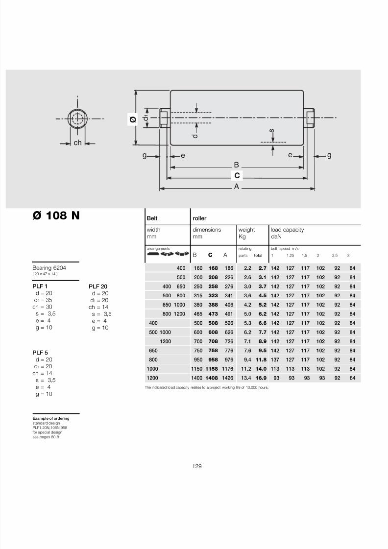
7/27/2019 31801183 Idler Roller
http://slidepdf.com/reader/full/31801183-idler-roller 131/308
129
The ind icated lo ad capacity relates to a project working life of 10.000 hours.
Belt roller
width dimensions weight load capacitymm mm Kg daN
arrangements rotating belt speed m/s
B C A parts total 1 1.25 1.5 2 2.5 3
400 160 168 186 2.2 2.7 142 127 117 102 92 84
500 200 208 226 2.6 3.1 142 127 117 102 92 84
400 650 250 258 276 3.0 3.7 142 127 117 102 92 84
500 800 315 323 341 3.6 4.5 142 127 117 102 92 84
650 1000 380 388 406 4.2 5.2 142 127 117 102 92 84
800 1200 465 473 491 5.0 6.2 142 127 117 102 92 84
400 500 508 526 5.3 6.6 142 127 117 102 92 84
500 1000 600 608 626 6.2 7.7 142 127 117 102 92 84
1200 700 708 726 7.1 8.9 142 127 117 102 92 84
650 750 758 776 7.6 9.5 142 127 117 102 92 84
800 950 958 976 9.4 11.8 137 127 117 102 92 84
1000 1150 1158 1176 11.2 14.0 113 113 113 102 92 84
1200 1400 1408 1426 13.4 16.9 93 93 93 93 92 84
B
A
ø
C
s
e e
d
d 1
ch
g g
Ø 108 N
Bearing 6204( 20 x 47 x 14 )
PLF 1d = 20
d 1 = 35ch = 30
s = 3,5e = 4g = 10
PLF 5d = 20
d 1 = 20ch = 14
s = 3,5e = 4g = 10
Example of orderingstandard designPLF1,20N,108N,958for special designsee pages 80-81
PLF 20d = 20
d 1 = 20ch = 14
s = 3,5e = 4g = 10
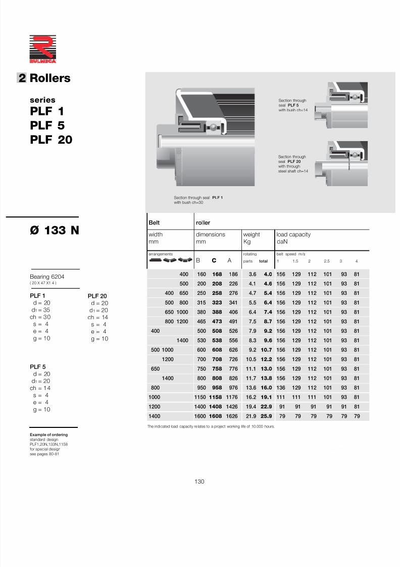
7/27/2019 31801183 Idler Roller
http://slidepdf.com/reader/full/31801183-idler-roller 132/308
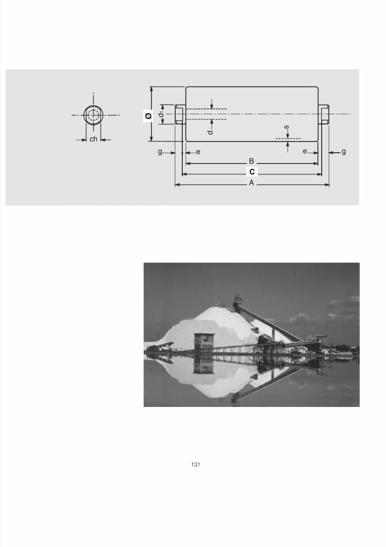
7/27/2019 31801183 Idler Roller
http://slidepdf.com/reader/full/31801183-idler-roller 133/308

7/27/2019 31801183 Idler Roller
http://slidepdf.com/reader/full/31801183-idler-roller 134/308
132
®
2 Rollers
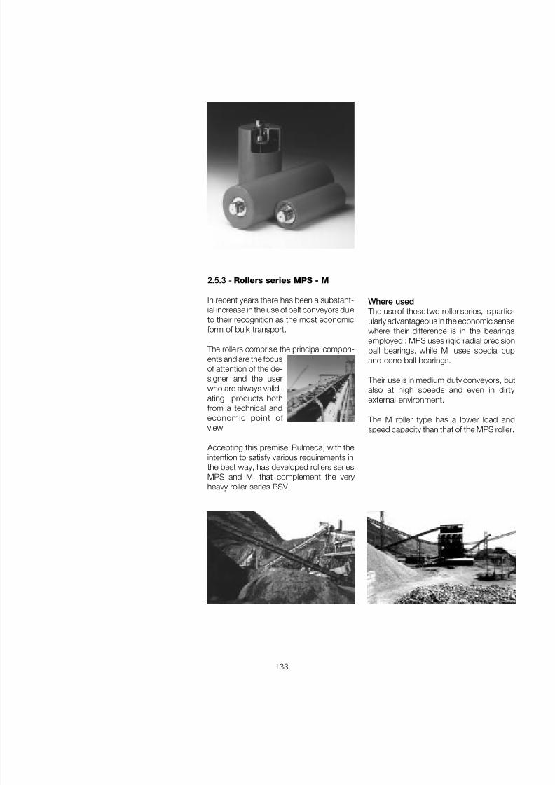
7/27/2019 31801183 Idler Roller
http://slidepdf.com/reader/full/31801183-idler-roller 135/308
133
2.5.3 - Rollers series MPS - M
In recent years there has been a substant-ial increase in the use of belt conveyors dueto their recognition as the most economicform of bulk transport.
The rollers comprise the principal compon-ents and are the focusof attention of the de-signer and the userwho are always valid-ating products bothfrom a technical andeconomic point of view.
Accepting this premise, Rulmeca, with theintention to satisfy various requirements inthe best way, has developed rollers seriesMPS and M, that complement the veryheavy roller series PSV.
Where used The use of these two roller series, is partic-ularly advantageous in the economic sensewhere their difference is in the bearingsemployed : MPS uses rigid radial precisionball bearings, while M uses special cupand cone ball bearings.
Their use is in medium duty conveyors, butalso at high speeds and even in dirtyexternal environment.
The M roller type has a lower load andspeed capacity than that of the MPS roller.
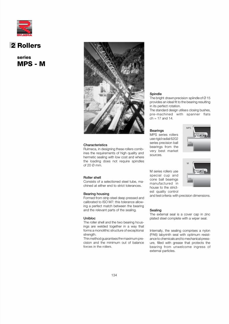
7/27/2019 31801183 Idler Roller
http://slidepdf.com/reader/full/31801183-idler-roller 136/308
134
®
2 Rollers
series
MPS - M
CharacteristicsRulmeca, in designing these rollers comb-ines the requirements of high quality andhermetic sealing with low cost and wherethe loading does not require spindlesof 20 Ø mm.
Roller shellConsists of a selectioned steel tube, ma-chined at either end to strict tolerances.
Bearing housingFormed from strip steel deep pressed andcalibrated to ISO M7: this tolerance allow-ing a perfect match between the bearingand the relevant parts of the sealing.
Unibloc
The roller shell and the two bearing hous-ings are welded together in a way thatforms a monolithic structure of exceptionalstrength.
This method guarantees the maximum pre-cision and the minimum out of balanceforces in the rollers.
Sealing The external seal is a cover cap in zincplated steel complete with a wiper seal.
Internally, the sealing comprises a nylon(PA6) labyrinth seal with optimum resist-ance to chemicals and to mechanical press-ure, filled with grease that protects thebearing from unwelcome ingress of external particles.
M
MPS
Spindle The bright drawn precision spìindle of Ø 15provides an ideal fit to the bearing resultingin its perfect rotation.
The standard design utilises closing bushes,pre-machined with spanner flatsch = 17 and 14.
BearingsMPS series rollersuse rigid radial 6202series precision ballbearings from thevery best marketsources.
M series rollers usespecial cup andcone ball bearingsmanufactured inhouse to the strict-est quality controland test criteria with precision dimensions.
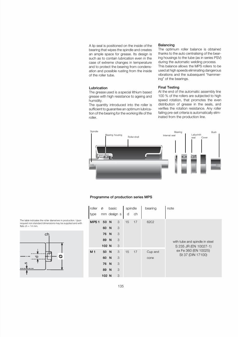
7/27/2019 31801183 Idler Roller
http://slidepdf.com/reader/full/31801183-idler-roller 137/308
135
Balancing The optimum roller balance is obtainedthanks to the auto centralising of the bear-
ing housings to the tube (as in series PSV)during the automatic welding process.
This balance allows the MPS rollers to beused at high speeds eliminating dangerousvibrations and the subsequent “hammer-ing” of the bearings.
Final Testing At the end of the automatic assembly line100 % of the rollers are subjected to highspeed rotation, that promotes the evendistribution of grease in the seals, andverifies the rotation resistance. Any rollerfailing pre-set criteria is automatically elim-inated from the production line.
A lip seal is positioned on the inside of thebearing that wipes the spindle and createsan ample space for grease. Its design issuch as to contain lubrication even in thecase of extreme changes in temperatureand to protect the bearing from condens-ation and possible rusting from the insideof the roller tube.
Lubrication The grease used is a special lithium basedgrease with high resistance to ageing andhumidity.
The quantity introduced into the roller issufficient to guarantee an optimum lubrica-tion of the bearing for the working life of theroller.
Programme of production series MPS
roller ø basic spindle bearing note
type mm design s d ch
MPS 1 50 N 3 15 17 6202
60 N 3
76 N 3
89 N 3
102 N 3
M 1 50 N 3 15 17 Cup and
60 N 3 cone
76 N 3
89 N 3
102 N 3
The table ind icates the rol ler diamet ers in prod uction. Uponrequest non standard dimensions may be supplied and withflats ch = 14 mm.
ø
s
ch
d
Bush
Cover
BearingInternal seal
Spindle
Roller shellBearing housing Labyrinth
seal
with tube and spindle in steelS 235 JR (EN 10027-1)ex Fe 360 (EN 10025)
St 37 (DIN 17100)
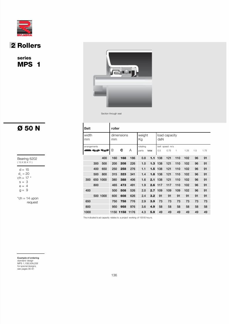
7/27/2019 31801183 Idler Roller
http://slidepdf.com/reader/full/31801183-idler-roller 138/308
136
®
2 Rollers
Belt roller
width dimensions weight load capacitymm mm Kg daN
arrangements rotating belt speed m/s
B C A parts total 0.5 0.75 1 1.25 1.5 1.75
400 160 168 186 0.8 1.1 138 121 110 102 96 91
300 500 200 208 226 1.0 1.3 138 121 110 102 96 91
400 650 250 258 276 1.1 1.5 138 121 110 102 96 91
500 800 315 323 341 1.4 1.8 138 121 110 102 96 91
300 650 1000 380 388 406 1.6 2.1 138 121 110 102 96 91
800 465 473 491 1.9 2.6 117 117 110 102 96 91
400 500 508 526 2.0 2.7 109 109 109 102 96 91
500 1000 600 608 626 2.4 3.2 91 91 91 91 91 91
650 750 758 776 2.9 3.9 73 73 73 73 73 73
800 950 958 976 3.6 4.9 58 58 58 58 58 58
1000 1150 1158 1176 4.3 5.9 49 49 49 49 49 49
series
MPS 1
Ø 50 N
Bearing 6202( 15 X 35 X 11 )
d = 15d 1 = 20
ch = 17 *s = 3e = 4g = 9
*ch = 14 uponrequest
Example of orderingstandard designMPS 1,15B,50N,208for special designssee pages 80-81
The in dicated lo ad capacity relates to a project working of 100 00 hou rs.
Section through seal
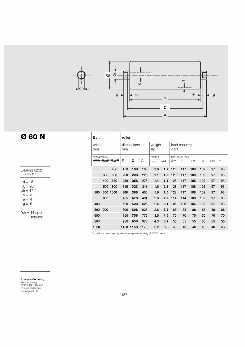
7/27/2019 31801183 Idler Roller
http://slidepdf.com/reader/full/31801183-idler-roller 139/308
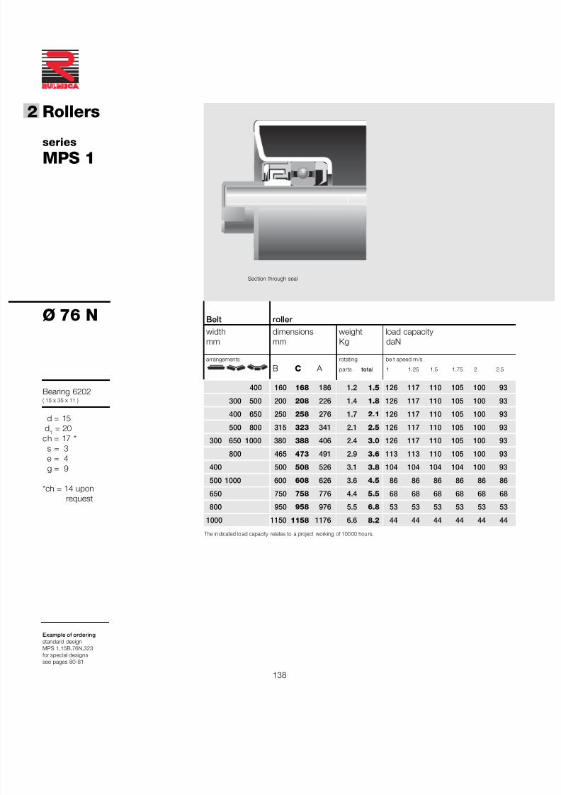
7/27/2019 31801183 Idler Roller
http://slidepdf.com/reader/full/31801183-idler-roller 140/308
138
®
2 Rollers
Belt roller width dimensions weight load capacitymm mm Kg daN
arrangements rotating belt speed m/s
B C A parts total 1 1.25 1.5 1.75 2 2.5
400 160 168 186 1.2 1.5 126 117 110 105 100 93
300 500 200 208 226 1.4 1.8 126 117 110 105 100 93
400 650 250 258 276 1.7 2.1 126 117 110 105 100 93
500 800 315 323 341 2.1 2.5 126 117 110 105 100 93
300 650 1000 380 388 406 2.4 3.0 126 117 110 105 100 93
800 465 473 491 2.9 3.6 113 113 110 105 100 93
400 500 508 526 3.1 3.8 104 104 104 104 100 93
500 1000 600 608 626 3.6 4.5 86 86 86 86 86 86
650 750 758 776 4.4 5.5 68 68 68 68 68 68
800 950 958 976 5.5 6.8 53 53 53 53 53 53
1000 1150 1158 1176 6.6 8.2 44 44 44 44 44 44
series
MPS 1
Ø 76 N
Bearing 6202( 15 x 35 x 11 )
d = 15d 1 = 20
ch = 17 *s = 3e = 4g = 9
*ch = 14 uponrequest
Example of orderingstandard designMPS 1,15B,76N,323for special designssee pages 80-81
The in dicated lo ad capacity relates to a project working of 100 00 hou rs.
Section through seal
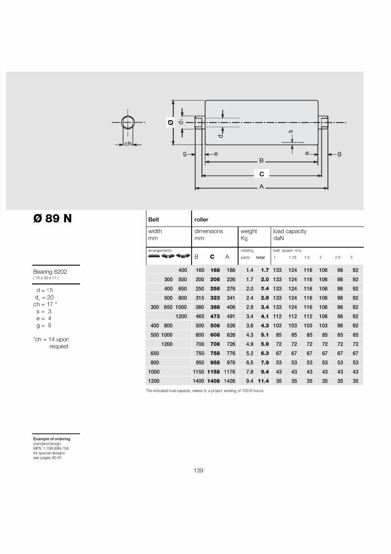
7/27/2019 31801183 Idler Roller
http://slidepdf.com/reader/full/31801183-idler-roller 141/308
139
Belt roller
width dimensions weight load capacitymm mm Kg daN
arrangements rotating belt speed m/s
B C A parts total 1 1.25 1.5 2 2.5 3
400 160 168 186 1.4 1.7 133 124 116 106 98 92
300 500 200 208 226 1.7 2.0 133 124 116 106 98 92
400 650 250 258 276 2.0 2.4 133 124 116 106 98 92
500 800 315 323 341 2.4 2.9 133 124 116 106 98 92
300 650 1000 380 388 406 2.9 3.4 133 124 116 106 98 92
1200 465 473 491 3.4 4.1 112 112 112 106 98 92
400 800 500 508 526 3.6 4.3 103 103 103 103 98 92
500 1000 600 608 626 4.3 5.1 85 85 85 85 85 85
1200 700 708 726 4.9 5.9 72 72 72 72 72 72
650 750 758 776 5.2 6.3 67 67 67 67 67 67
800 950 958 976 6.5 7.9 53 53 53 53 53 53
1000 1150 1158 1176 7.8 9.4 43 43 43 43 43 43
1200 1400 1408 1426 9.4 11.4 35 35 35 35 35 35
Ø 89 N
Bearing 6202( 15 x 35 x 11 )
d = 15d 1 = 20
ch = 17 *s = 3e = 4g = 9
*ch = 14 uponrequest
Example of orderingstandard designMPS 1,15B,89N,758for special designssee pages 80-81
The ind icated lo ad capacity relates to a project working of 100 00 hou rs.
B
A
ø d 1
C
s
e e
ch d
g g

7/27/2019 31801183 Idler Roller
http://slidepdf.com/reader/full/31801183-idler-roller 142/308
140
®
2 Rollers
Belt roller width dimensions weight load capacitymm mm Kg daN
arrangements rotating belt speed m/s
B C A parts total 1 1.25 1.5 2 2,5 3
400 160 168 186 1.7 1.9 139 129 122 111 103 97
300 500 200 208 226 2.0 2.3 139 129 122 111 103 97
400 650 250 258 276 2.3 2.7 139 129 122 111 103 97
500 800 315 323 341 2.8 3.3 139 129 122 111 103 97
300 650 1000 380 388 406 3.3 3.9 139 129 122 111 103 97
800 1200 465 473 491 3.9 4.6 112 112 112 111 103 97
400 500 508 526 4.2 4.9 103 103 103 103 103 97
500 1000 600 608 626 4.9 5.8 85 85 85 85 85 85
1200 700 708 726 5.6 6.6 72 72 72 72 72 72
650 750 758 776 6.0 7.1 67 67 67 67 67 67
800 950 958 976 7.5 8.8 52 52 52 52 52 52
1000 1150 1158 1176 8.9 10.6 43 43 43 43 43 43
1200 1400 1408 1426 10.8 12.7 35 35 35 35 35 35
series
MPS 1
Ø102 N
Bearing 6202( 15 x 35 x 11 )
d = 15d 1 = 20
ch = 17 *s = 3e = 4g = 9
*ch = 14 uponrequest
Example of orderingstandard designMPS 1,15B,102N,388for special designssee pages 80-81
The in dicated lo ad capacity relates to a project working of 100 00 hou rs.
Section through seal
7/27/2019 31801183 Idler Roller
http://slidepdf.com/reader/full/31801183-idler-roller 143/308
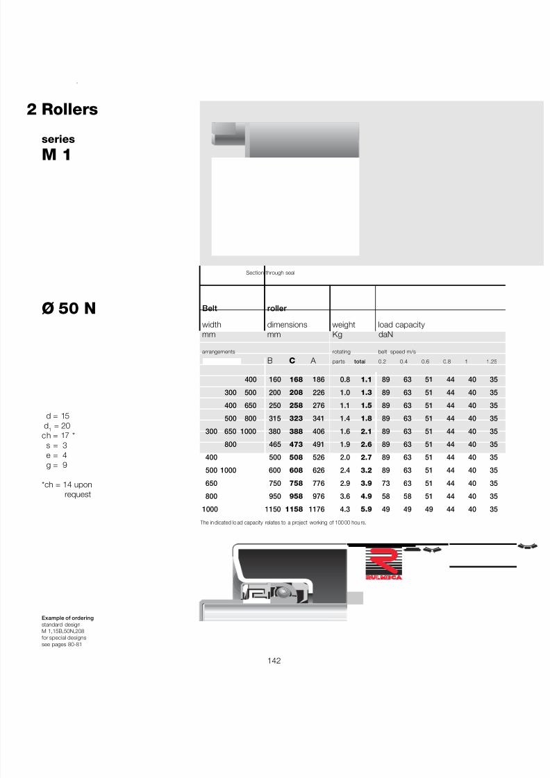
7/27/2019 31801183 Idler Roller
http://slidepdf.com/reader/full/31801183-idler-roller 144/308
142
®
2 Rollers
Belt roller
width dimensions weight load capacitymm mm Kg daN
arrangements rotating belt speed m/s
B C A parts total 0.2 0.4 0.6 0.8 1 1.25
400 160 168 186 0.8 1.1 89 63 51 44 40 35
300 500 200 208 226 1.0 1.3 89 63 51 44 40 35
400 650 250 258 276 1.1 1.5 89 63 51 44 40 35
500 800 315 323 341 1.4 1.8 89 63 51 44 40 35
300 650 1000 380 388 406 1.6 2.1 89 63 51 44 40 35
800 465 473 491 1.9 2.6 89 63 51 44 40 35
400 500 508 526 2.0 2.7 89 63 51 44 40 35
500 1000 600 608 626 2.4 3.2 89 63 51 44 40 35
650 750 758 776 2.9 3.9 73 63 51 44 40 35
800 950 958 976 3.6 4.9 58 58 51 44 40 35
1000 1150 1158 1176 4.3 5.9 49 49 49 44 40 35
series
M 1
Ø 50 N
Cup and conebearing
d = 15d 1 = 20
ch = 17 *s = 3e = 4g = 9
*ch = 14 uponrequest
Example of orderingstandard designM 1,15B,50N,208for special designssee pages 80-81
The in dicated lo ad capacity relates to a project working of 100 00 hou rs.
Section through seal
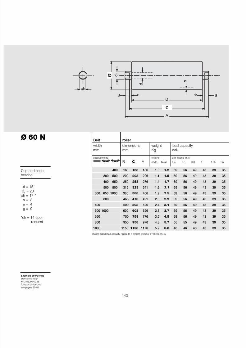
7/27/2019 31801183 Idler Roller
http://slidepdf.com/reader/full/31801183-idler-roller 145/308
143
Belt roller width dimensions weight load capacitymm mm Kg daN
arrangements rotating belt speed m/s
B C A parts total 0.4 0.6 0.8 1 1.25 1.5
400 160 168 186 1.0 1.2 69 56 49 43 39 35
300 500 200 208 226 1.1 1.5 69 56 49 43 39 35
400 650 250 258 276 1.4 1.7 69 56 49 43 39 35
500 800 315 323 341 1.6 2.1 69 56 49 43 39 35
300 650 1000 380 388 406 1.9 2.5 69 56 49 43 39 35
800 465 473 491 2.3 2.9 69 56 49 43 39 35
400 500 508 526 2.4 3.1 69 56 49 43 39 35
500 1000 600 608 626 2.8 3.7 69 56 49 43 39 35
650 750 758 776 3.5 4.5 69 56 49 43 39 35
800 950 958 976 4.3 5.7 55 55 49 43 39 35
1000 1150 1158 1176 5.2 6.8 46 46 46 43 39 35
Ø 60 N
Cup and conebearing
d = 15d 1 = 20
ch = 17 *s = 3e = 4g = 9
*ch = 14 uponrequest
Example of orderingstandard designM1,15B,60N,258for special designssee pages 80-81
The ind icated lo ad capacity relates to a project working of 100 00 hou rs.
B
A
ø d 1
C
s
e e
ch d
g g
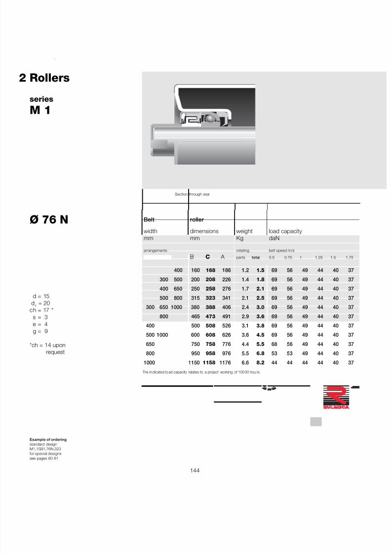
7/27/2019 31801183 Idler Roller
http://slidepdf.com/reader/full/31801183-idler-roller 146/308
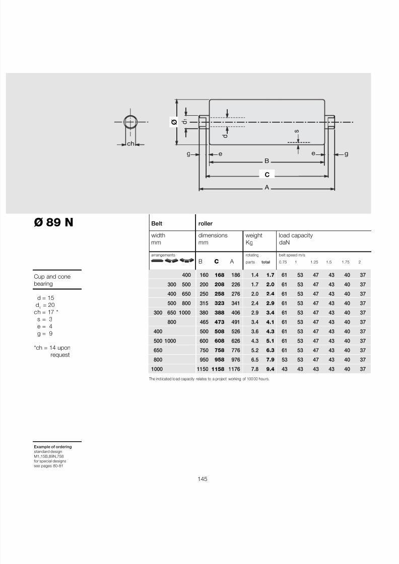
7/27/2019 31801183 Idler Roller
http://slidepdf.com/reader/full/31801183-idler-roller 147/308
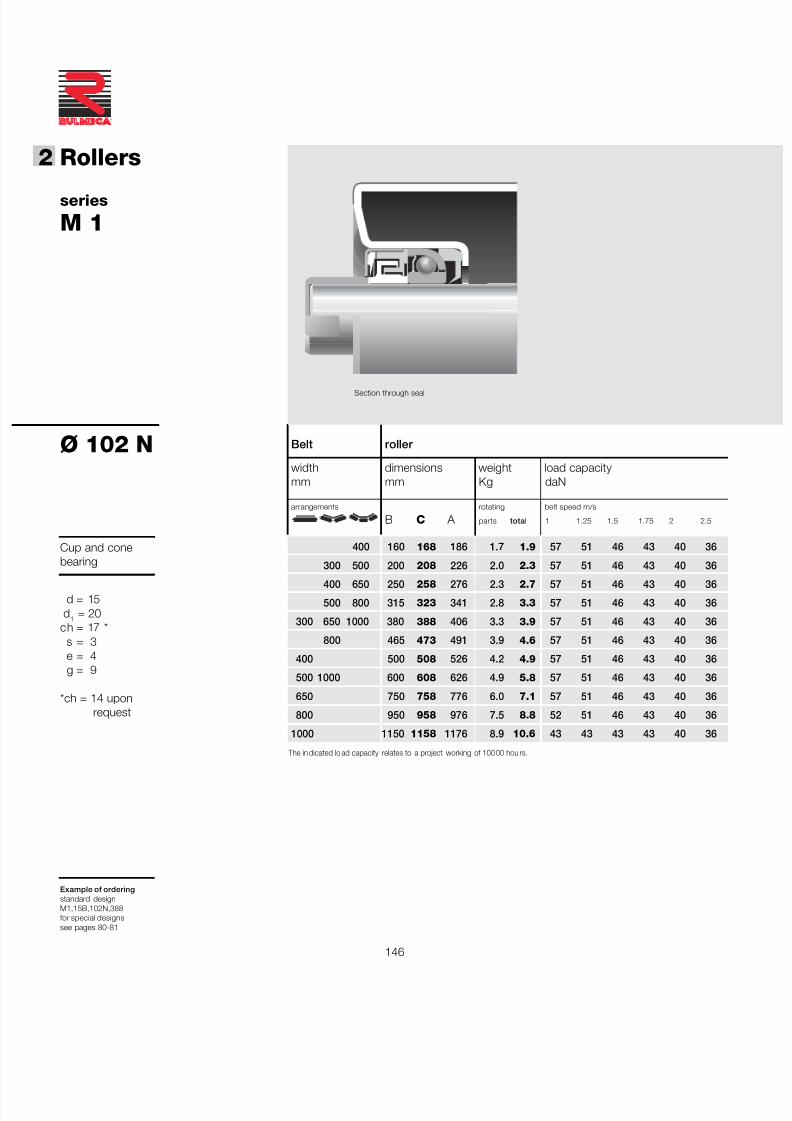
7/27/2019 31801183 Idler Roller
http://slidepdf.com/reader/full/31801183-idler-roller 148/308
146
®
2 Rollers
Belt roller
width dimensions weight load capacitymm mm Kg daN
arrangements rotating belt speed m/s
B C A parts total 1 1.25 1.5 1.75 2 2.5
400 160 168 186 1.7 1.9 57 51 46 43 40 36
300 500 200 208 226 2.0 2.3 57 51 46 43 40 36
400 650 250 258 276 2.3 2.7 57 51 46 43 40 36
500 800 315 323 341 2.8 3.3 57 51 46 43 40 36
300 650 1000 380 388 406 3.3 3.9 57 51 46 43 40 36
800 465 473 491 3.9 4.6 57 51 46 43 40 36
400 500 508 526 4.2 4.9 57 51 46 43 40 36
500 1000 600 608 626 4.9 5.8 57 51 46 43 40 36
650 750 758 776 6.0 7.1 57 51 46 43 40 36
800 950 958 976 7.5 8.8 52 51 46 43 40 36
1000 1150 1158 1176 8.9 10.6 43 43 43 43 40 36
series
M 1
Ø 102 N
Cup and conebearing
d = 15d 1 = 20
ch = 17 *s = 3e = 4g = 9
*ch = 14 uponrequest
Example of orderingstandard designM1,15B,102N,388for special designssee pages 80-81
The in dicated lo ad capacity relates to a project working of 100 00 hou rs.
Section through seal
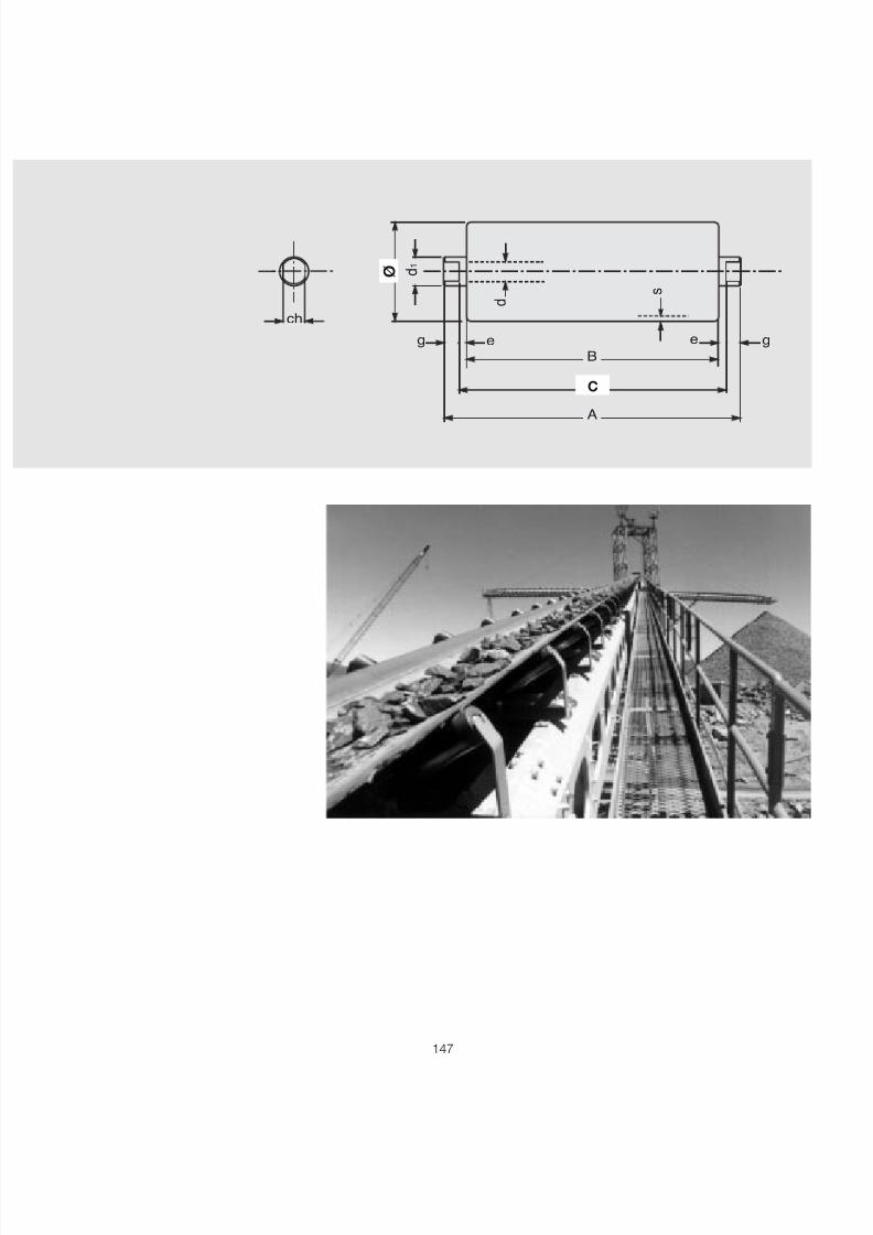
7/27/2019 31801183 Idler Roller
http://slidepdf.com/reader/full/31801183-idler-roller 149/308
147
B
A
ø d 1
C
s
e ech
d
g g

7/27/2019 31801183 Idler Roller
http://slidepdf.com/reader/full/31801183-idler-roller 150/308
148
®
2 Rollers
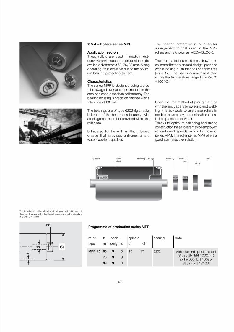
7/27/2019 31801183 Idler Roller
http://slidepdf.com/reader/full/31801183-idler-roller 151/308
149
Programme of production series MPR
roller ø basic spindle bearing note
type mm design s d ch
MPR 15 60 N 3 15 17 6202
76 N 3
89 N 3
ø
s
ch
d
Given that the method of joining the tubewith the end caps is by swaging (not weld-ing) it is advisable to use these rollers inmedium severe environments where thereis little presence of water.
Thanks to optimum balancing and strongconstruction these rollers may be employedat loads and speeds similar to those of series MPS. The roller series MPR offers agood cost effective solution.
The bearing protection is of a similararrangement to that used in the MPSrollers and is known as MECA-BLOCK.
The steel spindle is ø 15 mm, drawn andcalibrated in the standard design, providedwith a locking bush that has spanner flats(ch = 17) .The use is normally restrictedwithin the temperature range from -20 °
+100 ° C.
2.5.4 - Rollers series MPR
Application sectors
These rollers are used in medium dutyconveyors with speeds in proportion to theavailable diameters : 60, 76, 89 mm. A longoperating life is available due to the optim-um bearing protection system.
Characteristics The series MPR is designed using a steeltube swaged over at either end to join thesteel end caps in mechanical harmony. Thebearing housing is precision finished with atolerance of ISO M7.
The bearings are of type 6202 rigid radialball race of the best market supply, withample grease chamber provided within theroller seal.
Lubricated for life with a lithium basedgrease that provides anti-ageing andwater-repellent qualities.
Spindle Bearing
Cover
Labyrinthseal
BushBearing housingRollershell
The table indicates the roller diameters in production, On requestthey may be supplied with different dimensions to the standardand with ch=14 mm.
with tube and spindle in steelS 235 JR (EN 10027-1)ex Fe 360 (EN 10025)
St 37 (DIN 17100)

7/27/2019 31801183 Idler Roller
http://slidepdf.com/reader/full/31801183-idler-roller 152/308
150
®
2 Rollers
Belt roller
width dimensions weight load capacitymm mm Kg daN
arrangements rotating belt speed m/s
B C A parts total 0.5 0.75 1 1.25 1.5 1.75
400 160 168 186 0,9 1,2 147 128 117 108 102 97
300 500 200 208 226 1,1 1,4 147 128 117 108 102 97
400 650 250 258 276 1,3 1,7 147 128 117 108 102 97
500 800 315 323 341 1,6 2,1 147 128 117 108 102 97
300 650 1000 380 388 406 1,9 2,4 143 128 117 108 102 97
800 465 473 491 2,2 2,9 114 114 114 108 102 97
400 500 508 526 2,4 3,1 106 106 106 106 102 97
500 1000 600 608 626 2,8 3,7 88 88 88 88 88 88
650 750 758 776 3,4 4,5 70 70 70 70 70 70
800 950 958 976 4,3 5,6 55 55 55 55 55 55
1000 1150 1158 1176 5,1 6,7 46 46 46 46 46 46
series
MPR 15
Ø 60 N
Bearing 6202( 15 X 35 X 11 )
d = 15d 1 = 20ch = 17*
s = 3e = 4g = 9
*ch = 14 on request
Example of orderingstandard designMPR 15,60N,258for special designssee pages 80-81
The ind icated load capacity r elates to a project working life of 10.000 hours.
Section through seal
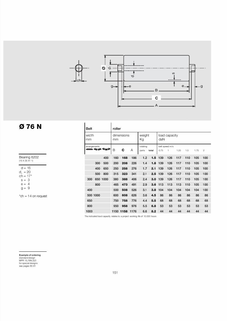
7/27/2019 31801183 Idler Roller
http://slidepdf.com/reader/full/31801183-idler-roller 153/308
151
Ø 76 N
Bearing 6202(15 X 35 X1 1)
d = 15d 1 = 20ch = 17*
s = 3e = 4g = 9
*ch = 14 on request
Example of orderingstandard designMPR 15,76N,323for special designssee pages 80-81
The ind icated loa d capacity relates to a project working life of 10.000 hours.
Belt roller
width dimensions weight load capacitymm mm Kg daN
arrangements rotating belt speed m/s
B C A parts total 0.75 1 1.25 1.5 1.75 2
400 160 168 186 1.2 1.5 139 126 117 110 105 100
300 500 200 208 226 1.4 1.8 139 126 117 110 105 100
400 650 250 258 276 1.7 2.1 139 126 117 110 105 100
500 800 315 323 341 2.1 2.5 139 126 117 110 105 100
300 650 1000 380 388 406 2.4 3.0 139 126 117 110 105 100
800 465 473 491 2.9 3.6 113 113 113 110 105 100
400 500 508 526 3.1 3.8 104 104 104 104 104 100
500 1000 600 608 626 3.6 4.5 86 86 86 86 86 86
650 750 758 776 4.4 5.5 68 68 68 68 68 68
800 950 958 976 5.5 6.8 53 53 53 53 53 53
1000 1150 1158 1176 6.6 8.2 44 44 44 44 44 44
B
A
ø d 1
C
s
e ech
d
g g
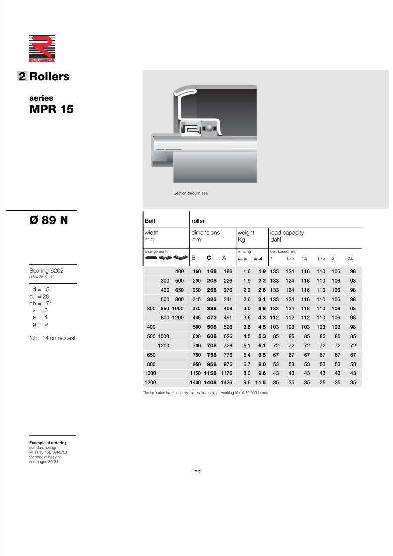
7/27/2019 31801183 Idler Roller
http://slidepdf.com/reader/full/31801183-idler-roller 154/308
152
®
2 Rollers
series
MPR 15
Ø 89 N
Bearing 6202(15 X 35 X 11 )
d = 15d 1 = 20ch = 17*
s = 3e = 4g = 9
*ch =14 on request
Example of orderingstandard designMPR 15,15B,89N,758for special designssee pages 80-81
The in dicated lo ad capacity relates to a project working life of 10.000 hours.
Section through seal
Belt roller
width dimensions weight load capacitymm mm Kg daN
arrangements rotating belt speed m/s
B C A parts total 1 1.25 1.5 1.75 2 2.5
400 160 168 186 1.6 1.9 133 124 116 110 106 98
300 500 200 208 226 1.9 2.2 133 124 116 110 106 98
400 650 250 258 276 2.2 2.6 133 124 116 110 106 98
500 800 315 323 341 2.6 3.1 133 124 116 110 106 98
300 650 1000 380 388 406 3.0 3.6 133 124 116 110 106 98
800 1200 465 473 491 3.6 4.3 112 112 112 110 106 98
400 500 508 526 3.8 4.5 103 103 103 103 103 98
500 1000 600 608 626 4.5 5.3 85 85 85 85 85 85
1200 700 708 726 5.1 6.1 72 72 72 72 72 72
650 750 758 776 5.4 6.5 67 67 67 67 67 67
800 950 958 976 6.7 8.0 53 53 53 53 53 53
1000 1150 1158 1176 8.0 9.6 43 43 43 43 43 43
1200 1400 1408 1426 9.6 11.5 35 35 35 35 35 35
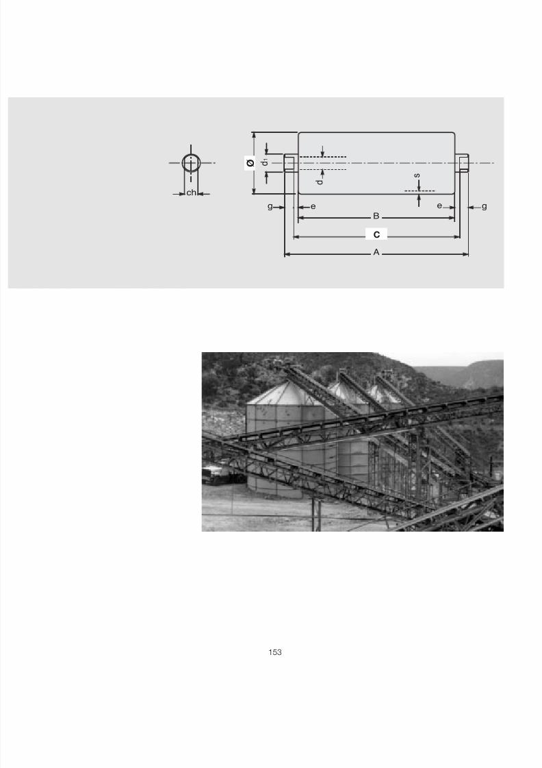
7/27/2019 31801183 Idler Roller
http://slidepdf.com/reader/full/31801183-idler-roller 155/308
153
B
A
ø d 1
C
s
e ech
d
g g

7/27/2019 31801183 Idler Roller
http://slidepdf.com/reader/full/31801183-idler-roller 156/308
154
®
2 Rollers
7/27/2019 31801183 Idler Roller
http://slidepdf.com/reader/full/31801183-idler-roller 157/308
155
A double radial labyrinth protects thebearing to allow use in medium severeenvironmental conditions.In the following tables the diameters inproduction are indicated with their loadsat varying recommended speeds.
Programme of production series RTL
roller ø basic spindle bearing notetype mm design s d ch
RTL 1 60 N 2 15 17 Cup and cone
76 N 2
89 N 2
BearingSpindle
Cover
BushLabyrinthseal
Roller shell
2.5.5 - Rollers series RTL
Where used
The roller series RTL has been designed tobe used in the movement of small or lightloads.
The roller consists of a special steel tubeswaged over the bearing housings whichare made from technopolymers which havehigh elastic properties, and resistance tomechanical forces and to corrosion.
The standard design utilises the specialcup and cone bearings, lubricated for life,a spindle of Ø15 mm with locking bush withspanner flats ch = 17 mm.
Bearing housing
ø
s
ch
d
The table indicates the roller diameters in production. On requestthey may be supplied with different dimensions to the standardand with ch = 14 mm.
with tube and spindle in steelS 235 JR (EN 10027-1)ex Fe 360 (EN 10025)
St 37 (DIN 17100)
7/27/2019 31801183 Idler Roller
http://slidepdf.com/reader/full/31801183-idler-roller 158/308
7/27/2019 31801183 Idler Roller
http://slidepdf.com/reader/full/31801183-idler-roller 159/308
157
Ø 76 N
Cup and conebearing
d = 15d 1 = 20
ch = 17 *s = 2e = 4g = 9
*ch = 14 on request
Example of orderingstandard designRTL 1,15B,76N,323for special designssee pages 80-81
The indi cated load capacity re lates to a project working life of 10.000 hours.
Belt roller
width dimensions weight load capacitymm mm Kg daN
arrangements rotating belt speedm/s
B C A parts total 0.5 0.75 1 1.25 1.5 1.75
400 160 168 186 0.8 1.1 69 56 49 44 40 37
300 500 200 208 226 1.0 1.3 69 56 49 44 40 37
400 650 250 258 276 1.1 1.5 69 56 49 44 40 37
500 800 315 323 341 1.4 1.8 69 56 49 44 40 37
300 650 1000 380 388 406 1.6 2.2 69 56 49 44 40 37
800 465 473 491 1.9 2.6 69 56 49 44 40 37
400 500 508 526 2.1 2.8 69 56 49 44 40 37
500 1000 600 608 626 2.4 3.3 69 56 49 44 40 37
650 750 758 776 3.0 4.0 68 56 49 44 40 37
800 950 958 976 3.7 5.0 53 53 49 44 40 37
1000 1150 1158 1176 4.4 6.1 44 44 44 44 40 37
B
A
ø d 1
C
s
e e
ch d
g g
7/27/2019 31801183 Idler Roller
http://slidepdf.com/reader/full/31801183-idler-roller 160/308
158
®
2 Rollers
series
RTL 1
Ø 89 N
Cup and conebearing
d = 15d 1 = 20
ch = 17 *s = 2e = 4g = 9
*ch =14 on request
Example of orderingstandard designRTL 1,15B,89N,758for special designssee pages 80-81
The in dicated lo ad capacity relates to a project working life of 10.000 hours.
Section through seal
Belt roller
width dimensions weight load capacitymm mm Kg daN
arrangements rotating belt speed m/s
B C A parts total 0.75 1 1.25 1.5 1.75 2
400 160 168 186 1.1 1.4 61 53 47 43 40 37
300 500 200 208 226 1.3 1.6 61 53 47 43 40 37
400 650 250 258 276 1.5 1.9 61 53 47 43 40 37
500 800 315 323 341 1.8 2.3 61 53 47 43 40 37
300 650 1000 380 388 406 2.1 2.6 61 53 47 43 40 37
800 465 473 491 2.4 3.1 61 53 47 43 40 37
400 500 508 526 2.6 3.3 61 53 47 43 40 37
500 1000 600 608 626 3.0 3.9 61 53 47 43 40 37
650 750 758 776 3.7 4.7 61 53 47 43 40 37
800 950 958 976 4.5 5.9 53 53 47 43 40 37
1000 1150 1158 1176 5.4 7.0 43 43 43 43 40 37
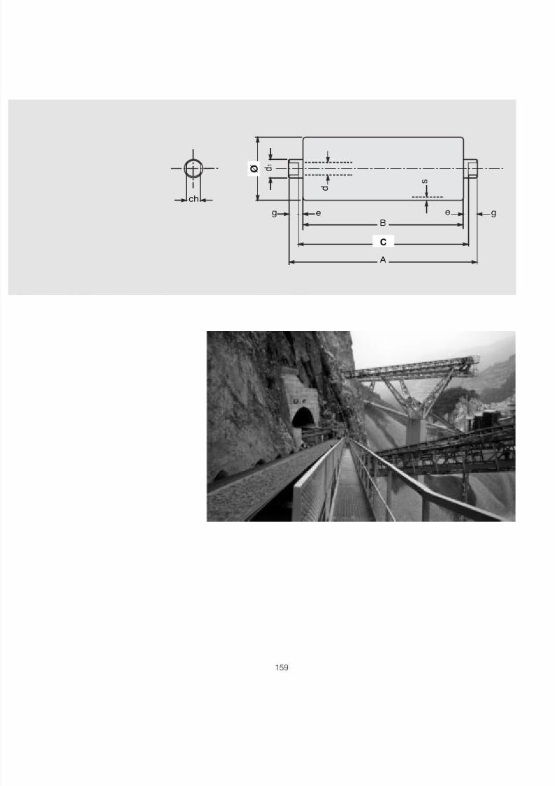
7/27/2019 31801183 Idler Roller
http://slidepdf.com/reader/full/31801183-idler-roller 161/308
159
B
A
ø d 1
C
s
e ech
d
g g

7/27/2019 31801183 Idler Roller
http://slidepdf.com/reader/full/31801183-idler-roller 162/308
160
®
2 Rollers
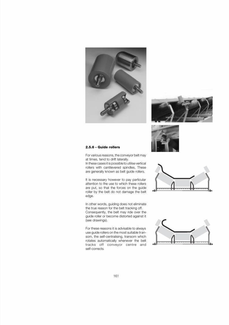
7/27/2019 31801183 Idler Roller
http://slidepdf.com/reader/full/31801183-idler-roller 163/308
161
2.5.6 - Guide rollers
For various reasons, the conveyor belt mayat times, tend to drift laterally.In these cases it is possible to utilise vertical
rollers with cantilevered spindles, Theseare generally known as belt guide rollers.
It is necessary however to pay particularattention to the use to which these rollersare put, so that the forces on the guideroller by the belt do not damage the beltedge.
In other words, guiding does not eliminatethe true reason for the belt tracking off.Consequently, the belt may ride over theguide roller or become distorted against it(see drawings).
For these reasons it is advisable to alwaysuse guide rollers on the most suitable tran-som, the self-centralising, transom whichrotates automatically whenever the belttracks off conveyor centre andself-corrects.
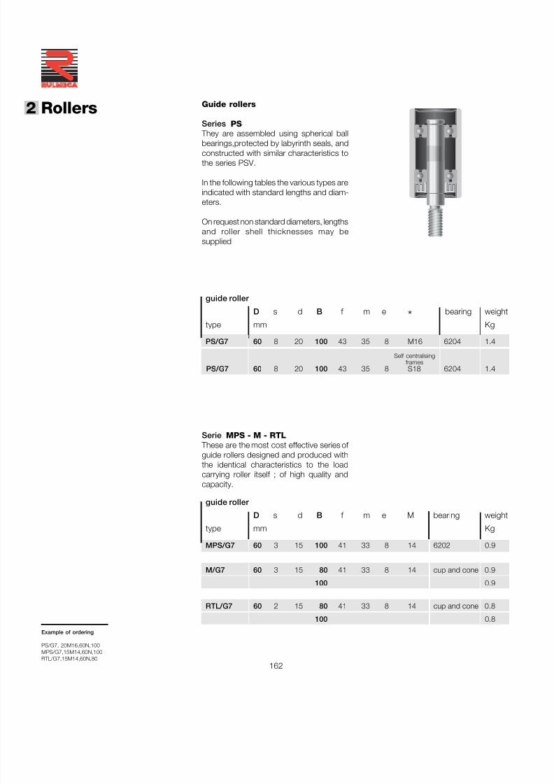
7/27/2019 31801183 Idler Roller
http://slidepdf.com/reader/full/31801183-idler-roller 164/308
162
®
2 Rollers Guide rollers
Series PS
They are assembled using spherical ballbearings,protected by labyrinth seals, andconstructed with similar characteristics tothe series PSV.
In the following tables the various types areindicated with standard lengths and diam-eters.
On request non standard diameters, lengthsand roller shell thicknesses may besupplied
Serie MPS - M - RTL These are the most cost effective series of guide rollers designed and produced withthe identical characteristics to the loadcarrying roller itself ; of high quality andcapacity.
guide roller
D s d B f m e M bearing weight
type mm Kg
MPS/G7 60 3 15 100 41 33 8 14 6202 0.9
M/G7 60 3 15 80 41 33 8 14 cup and cone 0.9
100 0.9
RTL/G7 60 2 15 80 41 33 8 14 cup and cone 0.8
100 0.8
guide roller
D s d B f m e * bearing weight
type mm Kg
PS/G7 60 8 20 100 43 35 8 M16 6204 1.4
PS/G7 60 8 20 100 43 35 8 S18 6204 1.4
Example of ordering
PS/G7, 20M16,60N,100MPS/G7,15M14,60N,100RTL/G7,15M14,60N,80
Self centralisingframes
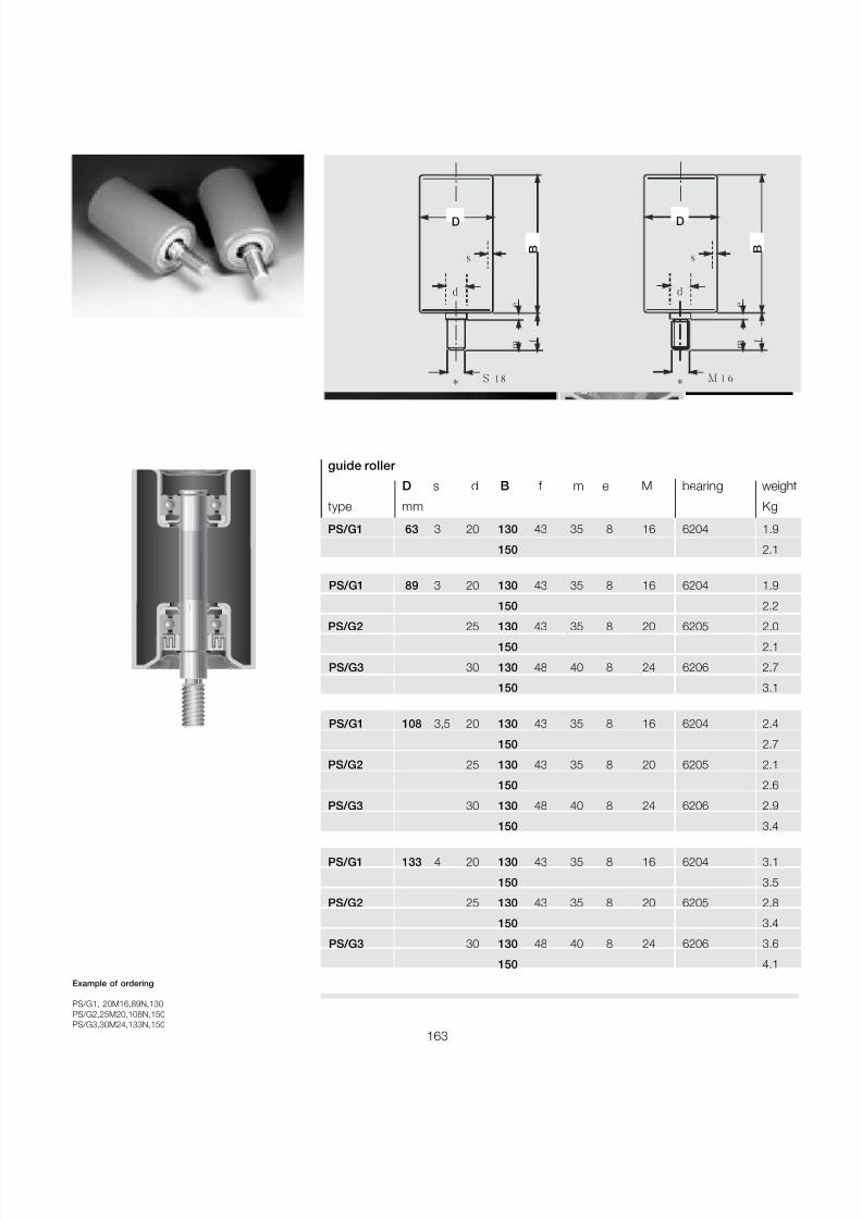
7/27/2019 31801183 Idler Roller
http://slidepdf.com/reader/full/31801183-idler-roller 165/308
163
D
d
s
M 16
mf
e
B
*
D
d
s
S 18
mf
e
B
*
guide roller
D s d B f m e M bearing weight
type mm Kg
PS/G1 63 3 20 130 43 35 8 16 6204 1.9
150 2.1
PS/G1 89 3 20 130 43 35 8 16 6204 1.9
150 2.2
PS/G2 25 130 43 35 8 20 6205 2.0150 2.1
PS/G3 30 130 48 40 8 24 6206 2.7
150 3.1
PS/G1 108 3,5 20 130 43 35 8 16 6204 2.4
150 2.7
PS/G2 25 130 43 35 8 20 6205 2.1
150 2.6
PS/G3 30 130 48 40 8 24 6206 2.9
150 3.4
PS/G1 133 4 20 130 43 35 8 16 6204 3.1
150 3.5
PS/G2 25 130 43 35 8 20 6205 2.8
150 3.4
PS/G3 30 130 48 40 8 24 6206 3.6
150 4.1
Example of ordering
PS/G1, 20M16,89N,130PS/G2,25M20,108N,150PS/G3,30M24,133N,150
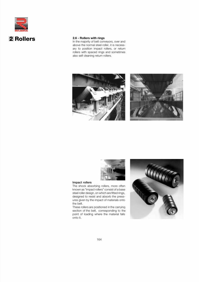
7/27/2019 31801183 Idler Roller
http://slidepdf.com/reader/full/31801183-idler-roller 166/308
164
®
2 Rollers 2.6 - Rollers with ringsIn the majority of belt conveyors, over andabove the normal steel roller, it is necess-
ary to position impact rollers, or returnrollers with spaced rings and sometimesalso self cleaning return rollers.
Impact rollers The shock absorbing rollers, more oftenknown as “impact rollers” consist of a base
steel roller design, on which are fitted rings,designed to resist and absorb the press-ures given by the impact of materials ontothe belt.
These rollers are positioned in the carryingsection of the belt, corresponding to thepoint of loading where the material fallsonto it.
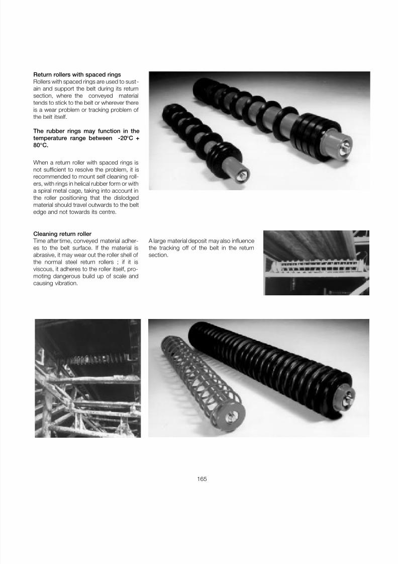
7/27/2019 31801183 Idler Roller
http://slidepdf.com/reader/full/31801183-idler-roller 167/308
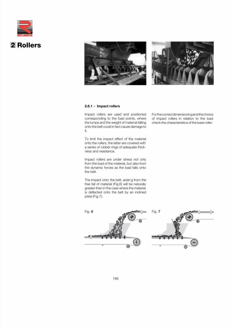
7/27/2019 31801183 Idler Roller
http://slidepdf.com/reader/full/31801183-idler-roller 168/308
166
®
2 Rollers
2.6.1 - Impact rollers
Impact rollers are used and positionedcorresponding to the load points, wherethe lumps and the weight of material fallingonto the belt could in fact cause damage toit.
To limit the impact effect of the materialonto the rollers, the latter are covered witha series of rubber rings of adequate thick-ness and resistance.
Impact rollers are under stress not onlyfrom the load of the material, but also from
the dynamic forces as the load falls ontothe belt.
The impact onto the belt, arising from thefree fall of material (Fig.6) will be naturallygreater than in the case where the materialis deflected onto the belt by an inclinedplate (Fig.7).
For the correct dimensioning and the choiceof impact rollers in relation to the loadcheck the characteristics of the base roller.
Fig. 6 Fig. 7
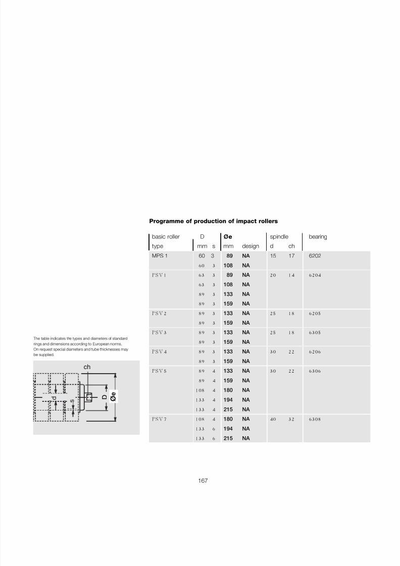
7/27/2019 31801183 Idler Roller
http://slidepdf.com/reader/full/31801183-idler-roller 169/308
167
The table indicates the types and diameters of standardrings and dimensions according to European norms.On request special diameters and tube thicknesses maybe supplied.
ø e
D d
ch
s
basic roller D ø e spindle bearing
type mm s mm design d ch
MPS 1 60 3 89 NA 15 17 6202
60 3 108 NA
P S V 1 63 3 89 NA 20 14 6204
63 3 108 NA
89 3 133 NA
89 3 159 NA
P S V 2 89 3 133 NA 25 18 6205
89 3 159 NA
P S V 3 89 3 133 NA 25 18 6305
89 3 159 NA
P S V 4 89 3 133 NA 30 22 6206
89 3 159 NA
P S V 5 89 4 133 NA 30 22 6306
89 4 159 NA
108 4 180 NA
133 4 194 NA
133 4 215 NA
P S V 7 108 4 180 NA 40 32 6308
133 6 194 NA
133 6 215 NA
Programme of production of impact rollers
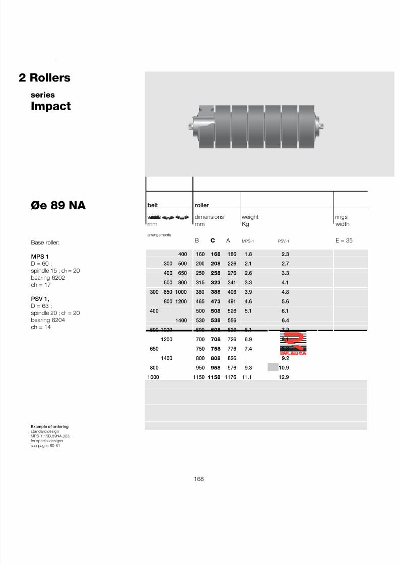
7/27/2019 31801183 Idler Roller
http://slidepdf.com/reader/full/31801183-idler-roller 170/308
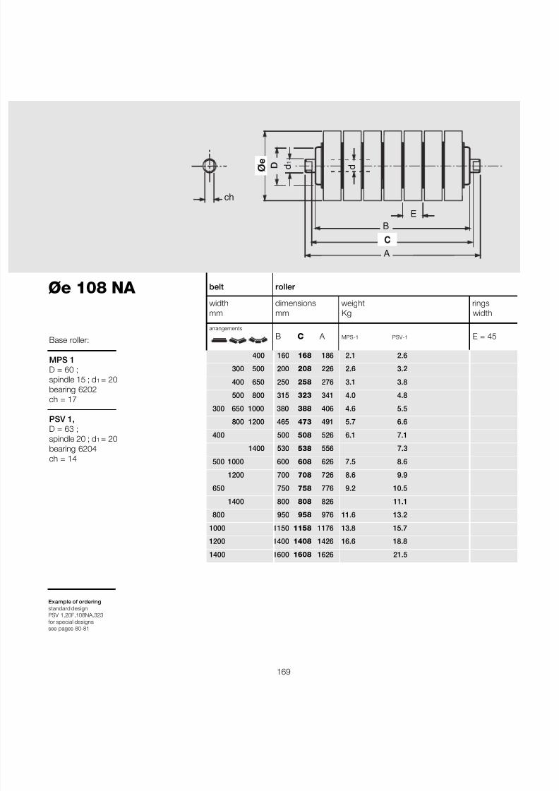
7/27/2019 31801183 Idler Roller
http://slidepdf.com/reader/full/31801183-idler-roller 171/308
169
belt roller
width dimensions weight ringsmm mm Kg width
arrangements
B C A MPS-1 PSV-1 E = 45
400 160 168 186 2.1 2.6
300 500 200 208 226 2.6 3.2
400 650 250 258 276 3.1 3.8
500 800 315 323 341 4.0 4.8
300 650 1000 380 388 406 4.6 5.5800 1200 465 473 491 5.7 6.6
400 500 508 526 6.1 7.1
1400 530 538 556 7.3
500 1000 600 608 626 7.5 8.6
1200 700 708 726 8.6 9.9
650 750 758 776 9.2 10.5
1400 800 808 826 11.1
800 950 958 976 11.6 13.2
1000 1150 1158 1176 13.8 15.7
1200 1400 1408 1426 16.6 18.81400 1600 1608 1626 21.5
Øe 108 NA
Example of orderingstandard designPSV 1,20F,108NA,323for special designssee pages 80-81
Base roller:
MPS 1D = 60 ;spindle 15 ; d 1 = 20bearing 6202ch = 17
PSV 1,D = 63 ;spindle 20 ; d 1 = 20bearing 6204ch = 14
B
A
ø e
C
ch
d 1
d D
E
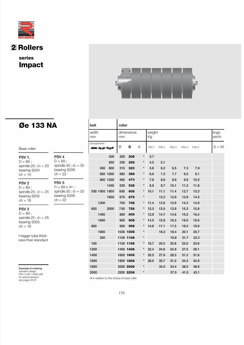
7/27/2019 31801183 Idler Roller
http://slidepdf.com/reader/full/31801183-idler-roller 172/308
170
®
2 Rollers
seriesImpact
Øe 133 NA
Example of orderingstandard designPSV 2,25F,133NA,388for special designssee pages 80-81
Base roller:
PSV 1,D = 89 ;spindle 20 ; d 1 = 20bearing 6204ch = 14
PSV 2D = 89 ;spindle 25 ; d 1 = 25bearing 6205ch = 18
PSV 3D = 89 ;spindle 25 ; d 1 = 25bearing 6305ch = 18
PSV 4D = 89 ;spindle 30 ; d 1 = 30bearing 6206ch = 22
PSV 5D = 89 x 4 * ;spindle 30 ; d 1 = 30bearing 6306ch = 22
* in relation to the choice of base roller
belt roller
width dimensions weight ringsmm mm Kg width
arrangements
B C A PSV 1 PSV 2 PSV 3 PSV 4 PSV 5 E = 35
500 200 208 * 3.7
650 250 258 * 4.5 5.1
500 800 315 323 * 5.6 6.2 6.5 7.3 7.9
650 1000 380 388 * 6.6 7.3 7.7 8.5 9.1
800 1200 465 473 * 7.8 8.6 8.9 9.9 10.5
1400 530 538 * 8.8 9.7 10.1 11.2 11.8
500 1000 1600 600 608 * 10.1 11.1 11.4 12.7 13.3
1800 670 678 * 12.2 12.6 13.9 14.5
1200 700 708 * 11.4 12.6 12.9 14.3 14.9
650 2000 750 758 * 12.3 13.5 13.9 15.3 15.9
1400 800 808 * 12.9 14.2 14.6 16.2 16.4
1600 900 908 * 14.5 15.9 16.3 18.0 18.6
800 950 958 * 14.6 17.1 17.5 19.3 19.9
1800 1000 1008 * 18.2 18.4 20.1 20.7
200 1100 1108 * 19.8 21.7 22.3100 1150 1158 * 18.7 20.5 20.8 23.0 23.6
1200 1400 1408 * 22.4 24.6 24.9 27.5 28.1
1400 1600 1608 * 25.5 27.9 28.3 31.2 31.8
1600 1800 1808 * 28.0 30.7 31.0 34.3 34.9
1800 2000 2008 * 34.0 34.4 38.0 38.6
2000 2200 2208 * 37.5 41.5 42.1
*bigger tube thick-ness than standard
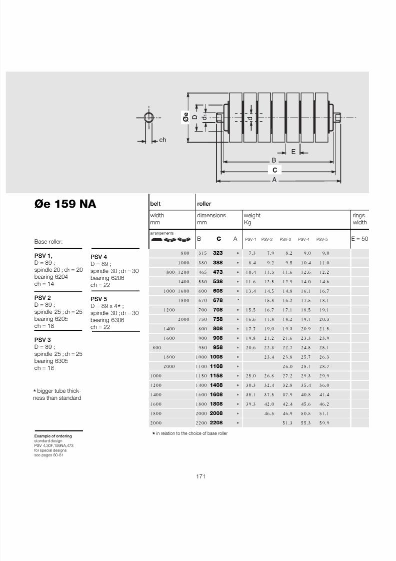
7/27/2019 31801183 Idler Roller
http://slidepdf.com/reader/full/31801183-idler-roller 173/308
171
Øe 159 NA
Example of orderingstandard designPSV 4,30F,159NA,473for special designssee pages 80-81
B
A
ø e
C
ch
d 1
d D
E
belt roller
width dimensions weight ringsmm mm Kg width
arrangements
B C A PSV-1 PSV-2 PSV-3 PSV-4 PSV-5 E = 5
800 315 323 * 7.3 7.9 8.2 9.0 9.0
1000 380 388 * 8.4 9.2 9.5 10.4 11.0
800 1200 465 473 * 10.4 11.3 11.6 12.6 12.2
1400 530 538 * 11.6 12.5 12.9 14.0 14.6
1000 1600 600 608 * 13.4 14.5 14.8 16.1 16.7
1800 670 678 * 15.8 16.2 17.5 18.1
1200 700 708 * 15.5 16.7 17.1 18.5 19.1
2000 750 758 * 16.6 17.8 18.2 19.7 20.3
1400 800 808 * 17.7 19,0 19.3 20.9 21.5
1600 900 908 * 19.8 21.2 21.6 23.3 23.9
800 950 958 * 20.6 22.3 22.7 24.5 25.1
1800 1000 1008 * 23.4 23.8 25.7 26.3
2000 1100 1108 * 26.0 28.1 28.7
1000 1150 1158 * 25.0 26.8 27.2 29.3 29.9
1200 1400 1408 * 30.3 32.4 32.8 35.4 36.0
1400 1600 1608 * 35.1 37.5 37.9 40.8 41.4
1600 1800 1808 * 39.3 42.0 42.4 45.6 46.2
1800 2000 2008 * 46.5 46.9 50.5 51.1
2000 2200 2208 * 51.3 55.3 59.9
* in relation to the choice of base roller
PSV 4D = 89 ;spindle 30 ; d 1 = 30bearing 6206ch = 22
PSV 5D = 89 x 4 * ;spindle 30 ; d 1 = 30bearing 6306ch = 22
Base roller:
PSV 1,D = 89 ;spindle 20 ; d 1 = 20bearing 6204ch = 14
PSV 2D = 89 ;spindle 25 ; d 1 = 25bearing 6205ch = 18
PSV 3D = 89 ;spindle 25 ; d 1 = 25bearing 6305ch = 18
*bigger tube thick-ness than standard
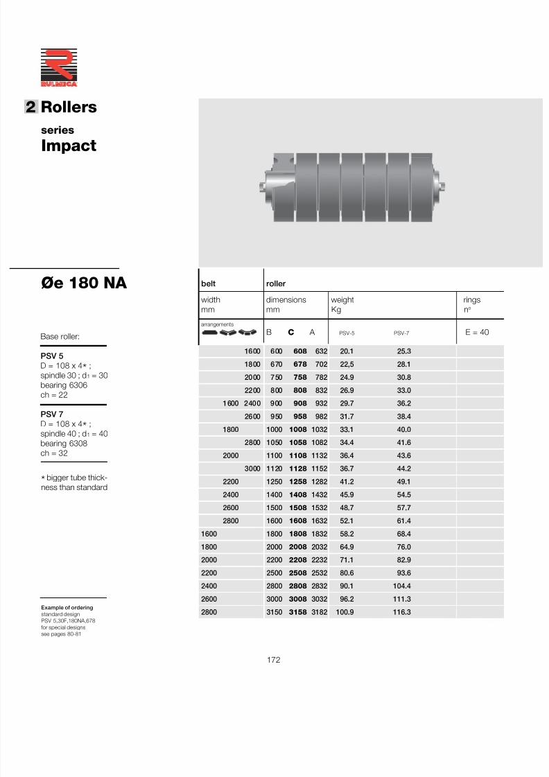
7/27/2019 31801183 Idler Roller
http://slidepdf.com/reader/full/31801183-idler-roller 174/308
172
®
2 Rollers
seriesImpact
Øe 180 NA
Example of orderingstandard designPSV 5,30F,180NA,678for special designssee pages 80-81
belt roller
width dimensions weight ringsmm mm Kg n o
arrangements
B C A PSV-5 PSV-7 E = 40
1600 600 608 632 20.1 25.3
1800 670 678 702 22,5 28.1
2000 750 758 782 24.9 30.8
2200 800 808 832 26.9 33.0
1600 2400 900 908 932 29.7 36.2
2600 950 958 982 31.7 38.4
1800 1000 1008 1032 33.1 40.0
2800 1050 1058 1082 34.4 41.6
2000 1100 1108 1132 36.4 43.6
3000 1120 1128 1152 36.7 44.2
2200 1250 1258 1282 41.2 49.1
2400 1400 1408 1432 45.9 54.5
2600 1500 1508 1532 48.7 57.7
2800 1600 1608 1632 52.1 61.4
1600 1800 1808 1832 58.2 68.41800 2000 2008 2032 64.9 76.0
2000 2200 2208 2232 71.1 82.9
2200 2500 2508 2532 80.6 93.6
2400 2800 2808 2832 90.1 104.4
2600 3000 3008 3032 96.2 111.3
2800 3150 3158 3182 100.9 116.3
Base roller:
PSV 5D = 108 x 4 * ;spindle 30 ; d 1 = 30bearing 6306ch = 22
PSV 7D = 108 x 4 * ;spindle 40 ; d 1 = 40bearing 6308ch = 32
*bigger tube thick-ness than standard
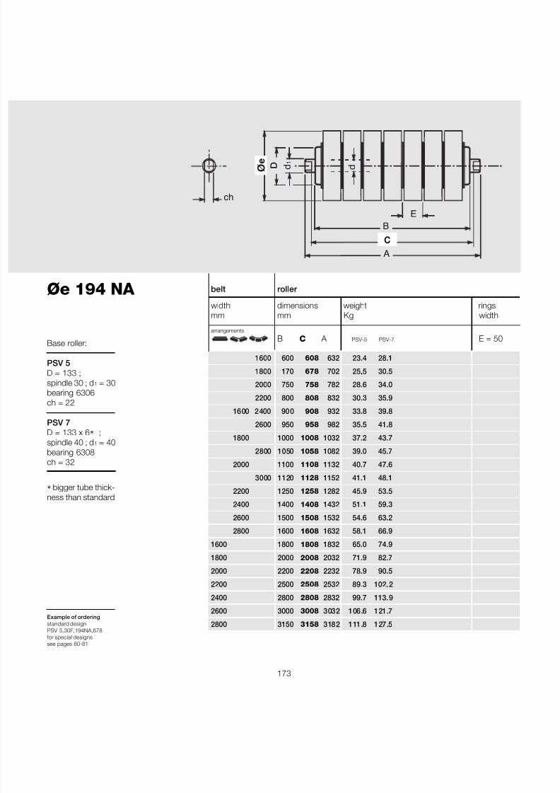
7/27/2019 31801183 Idler Roller
http://slidepdf.com/reader/full/31801183-idler-roller 175/308
173
B
A
ø e
C
ch
d 1
d D
E
belt roller
width dimensions weight ringsmm mm Kg width
arrangements
B C A PSV-5 PSV-7 E = 50
1600 600 608 632 23.4 28.1
1800 170 678 702 25,5 30.5
2000 750 758 782 28.6 34.0
2200 800 808 832 30.3 35.9
1600 2400 900 908 932 33.8 39.8
2600 950 958 982 35.5 41.8
1800 1000 1008 1032 37.2 43.7
2800 1050 1058 1082 39.0 45.7
2000 1100 1108 1132 40.7 47.6
3000 1120 1128 1152 41.1 48.1
2200 1250 1258 1282 45.9 53.5
2400 1400 1408 1432 51.1 59.3
2600 1500 1508 1532 54.6 63.2
2800 1600 1608 1632 58.1 66.9
1600 1800 1808 1832 65.0 74.91800 2000 2008 2032 71.9 82.7
2000 2200 2208 2232 78.9 90.5
2200 2500 2508 2532 89.3 102.2
2400 2800 2808 2832 99.7 113.9
2600 3000 3008 3032 106.6 121.7
2800 3150 3158 3182 111.8 127.5
Øe 194 NA
Example of orderingstandard designPSV 5,30F,194NA,678for special designssee pages 80-81
*bigger tube thick-ness than standard
Base roller:
PSV 5D = 133 ;spindle 30 ; d 1 = 30bearing 6306ch = 22
PSV 7D = 133 x 6 * ;spindle 40 ; d 1 = 40bearing 6308ch = 32
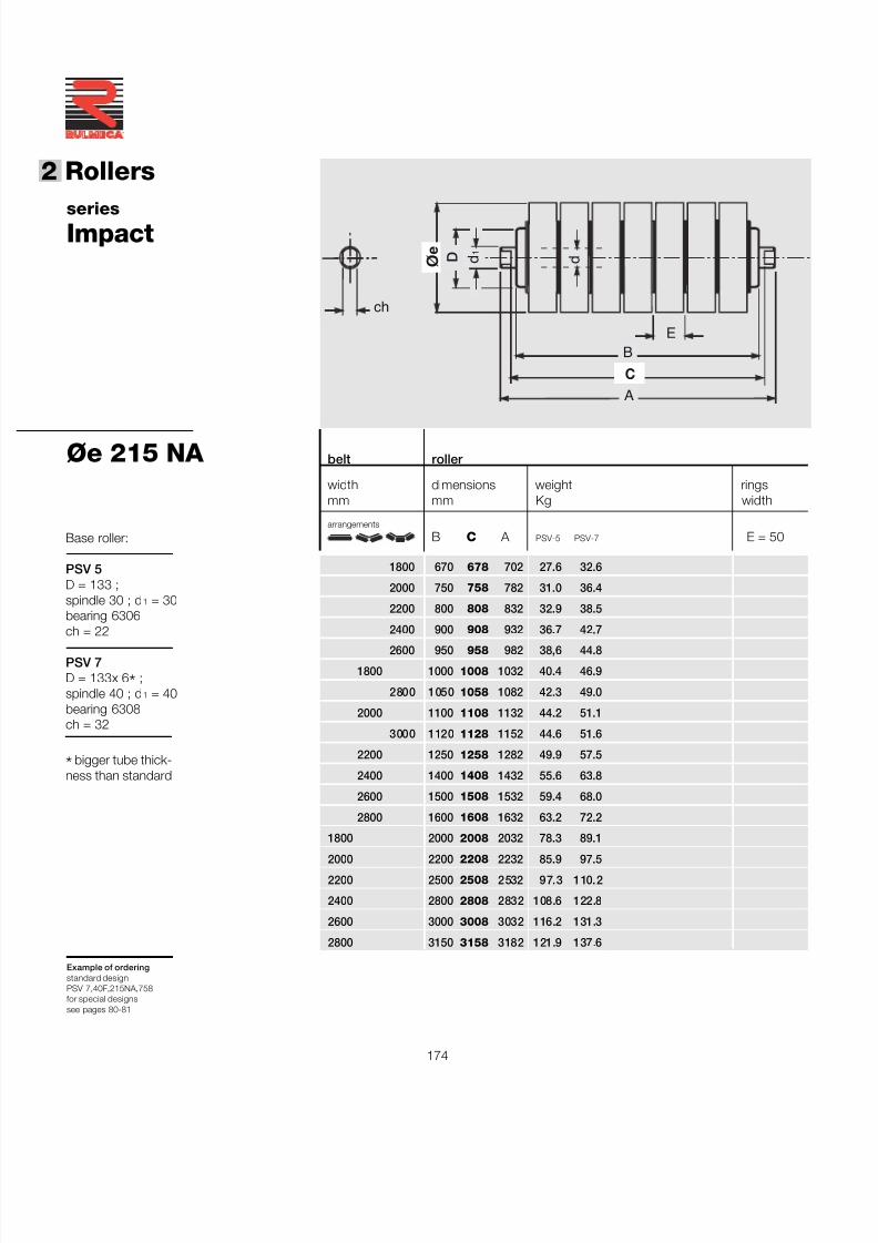
7/27/2019 31801183 Idler Roller
http://slidepdf.com/reader/full/31801183-idler-roller 176/308
174
®
2 Rollers
belt roller
width dimensions weight ringsmm mm Kg width
arrangements
B C A PSV-5 PSV-7 E = 50
1800 670 678 702 27.6 32.6
2000 750 758 782 31.0 36.4
2200 800 808 832 32.9 38.5
2400 900 908 932 36.7 42.7
2600 950 958 982 38,6 44.8
1800 1000 1008 1032 40.4 46.9
2800 1050 1058 1082 42.3 49.0
2000 1100 1108 1132 44.2 51.1
3000 1120 1128 1152 44.6 51.6
2200 1250 1258 1282 49.9 57.5
2400 1400 1408 1432 55.6 63.8
2600 1500 1508 1532 59.4 68.0
2800 1600 1608 1632 63.2 72.2
1800 2000 2008 2032 78.3 89.1
2000 2200 2208 2232 85.9 97.5
2200 2500 2508 2532 97.3 110.2
2400 2800 2808 2832 108.6 122.8
2600 3000 3008 3032 116.2 131.3
2800 3150 3158 3182 121.9 137.6
seriesImpact
Øe 215 NA
Example of orderingstandard designPSV 7,40F,215NA,758for special designssee pages 80-81
B
A
ø e
C
ch
d 1
d D
E
Base roller:
PSV 5D = 133 ;spindle 30 ; d 1 = 30bearing 6306ch = 22
PSV 7D = 133x 6 * ;spindle 40 ; d 1 = 40bearing 6308ch = 32
*bigger tube thick-ness than standard
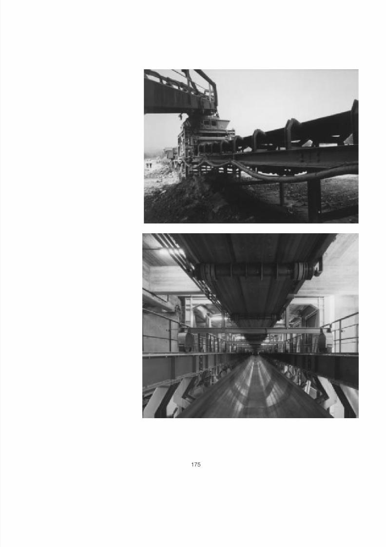
7/27/2019 31801183 Idler Roller
http://slidepdf.com/reader/full/31801183-idler-roller 177/308
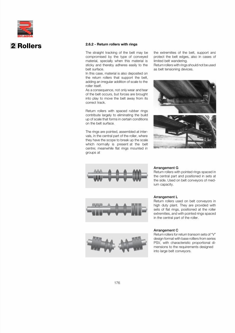
7/27/2019 31801183 Idler Roller
http://slidepdf.com/reader/full/31801183-idler-roller 178/308
176
®
2 Rollers 2.6.2 - Return rollers with rings
The straight tracking of the belt may be
compromised by the type of conveyedmaterial, specially when this material issticky and thereby adheres easily to thebelt surface.In this case, material is also deposited onthe return rollers that support the belt,adding an irregular addition of scale to theroller itself.
As a consequence, not only wear and tearof the belt occurs, but forces are broughtinto play to move the belt away from itscorrect track.
Return rollers with spaced rubber ringscontribute largely to eliminating the buildup of scale that forms in certain conditionson the belt surface.
The rings are pointed, assembled at inter-vals, in the central part of the roller, wherethey have the scope to break up the scalewhich normally is present at the beltcentre; meanwhile flat rings mounted ingroups at
Arrangement G
Return rollers with pointed rings spaced inthe central part and positioned in sets atthe side. Used on belt conveyors of med-ium capacity.
Arrangement LReturn rollers used on belt conveyors inhigh duty plant. They are provided withsets of flat rings, positioned at the rollerextremities, and with pointed rings spacedin the central part of the roller.
Arrangement CReturn rollers for return transom sets of “V”design format with base rolllers from seriesPSV, with characteristic proportional di-mensions to the requirements designedinto large belt conveyors.
the extremities of the belt, support and
protect the belt edges, also in cases of limited belt wandering.Return rollers with rings should not be usedas belt tensioning devices.
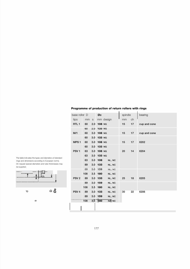
7/27/2019 31801183 Idler Roller
http://slidepdf.com/reader/full/31801183-idler-roller 179/308
177
base roller D ø e spindle bearing
tipo mm s mm design mm ch
RTL 1 60 2.0 108 NG 15 17 cup and cone
60 2.0 133 NG
M/1 60 3.0 108 NG 15 17 cup and cone
60 3.0 133 NGMPS 1 60 3.0 108 NG 15 17 6202
60 3.0 133 NG
PSV 1 63 3.0 108 NG 20 14 6204
63 3.0 133 NG
63 3.0 108 NL , NC
89 3.0 133 NL , NC
89 3.0 159 NL , NC
108 3.5 180 NL , NC
PSV 2 89 3.0 133 NL , NC 25 18 6205
89 3.0 159 NL , NC
108 3.5 180 NL , NC
PSV 4 89 3.0 133 NL , NC 30 22 6206
89 3.0 159 NL , NC
108 3.5 180 NL , NC
PSV 7 108 3.5 180 NL , NC 40 32 6308
Programme of production of return rollers with rings
The table indi cates the types and diameter s of standard
rings and dimensions according to European norms.
On request special diameters and tube thicknesses may
be supplied.
ø e
D d
ch
s
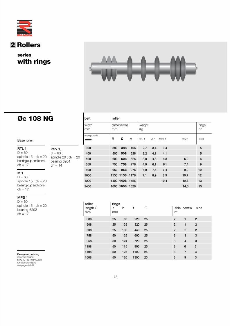
7/27/2019 31801183 Idler Roller
http://slidepdf.com/reader/full/31801183-idler-roller 180/308
178
®
2 Rollers
Example of orderingstandard designMPS 1,,15B,108NG,508for special designssee pages 80-81
belt roller
width dimensions weight ringsmm mm Kg n o
arrangements
B C A RTL-1 M -1 MPS-1 PSV-1 total
300 380 388 406 2,7 3,4 3,4 5
400 500 508 526 3,2 4,1 4,1 5
500 600 608 626 3,8 4,8 4,8 5,9 6
650 750 758 776 4,9 6,1 6,1 7,4 9
800 950 958 976 6,0 7,4 7,4 9,0 10
1000 1150 1158 1176 7,1 8,9 8,9 10,7 12
1200 1400 1408 1426 10,4 12,6 13
1400 1600 1608 1626 14,3 15
Øe 108 NG
Base roller:
RTL 1D = 60 ;spindle 15 ; d 1 = 20bearing cup and conech = 17
M 1D = 60 ;spindle 15 ; d 1 = 20bearing cup and conech = 17
MPS 1D = 60 ;spindle 15 ; d 1 = 20bearing 6202ch = 17
PSV 1,D = 63 ;spindle 20 ; d 1 = 20bearing 6204ch = 14
serieswith rings
roller ringslength C a b t E side central sidemm mm n o
388 25 85 220 25 2 1 2
508 25 135 320 25 2 1 2608 25 130 440 25 2 2 2
758 50 125 600 25 3 3 3
958 50 124 720 25 3 4 3
1158 50 115 905 25 3 6 3
1408 50 125 1100 25 3 7 3
1608 50 120 1300 25 3 9 3
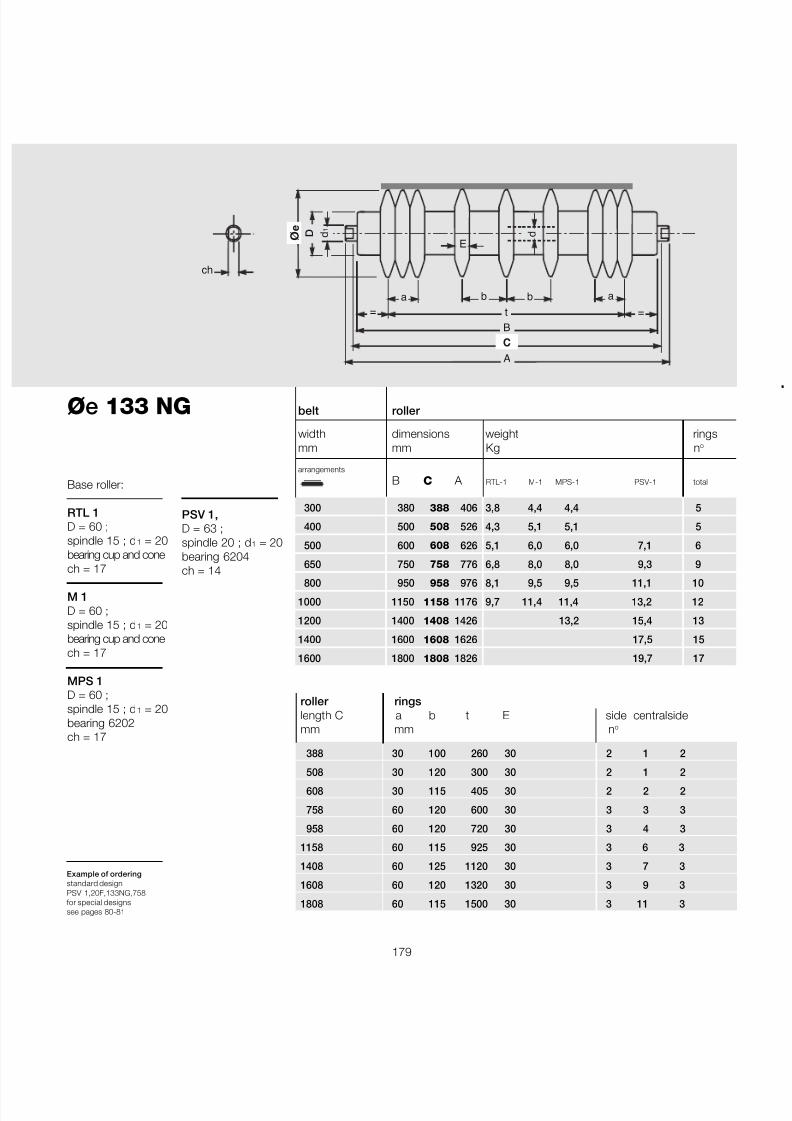
7/27/2019 31801183 Idler Roller
http://slidepdf.com/reader/full/31801183-idler-roller 181/308
179
Example of orderingstandard designPSV 1,20F,133NG,758for special designssee pages 80-81
Øe 133 NG
Base roller:
RTL 1D = 60 ;spindle 15 ; d 1 = 20bearing cup and conech = 17
M 1D = 60 ;spindle 15 ; d 1 = 20bearing cup and conech = 17
MPS 1D = 60 ;spindle 15 ; d 1 = 20bearing 6202ch = 17
B
A
ø e
C
ch
d 1
d D
E
a b b a= =t
belt roller
width dimensions weight ringsmm mm Kg n o
arrangements
B C A RTL-1 M-1 MPS-1 PSV-1 total
300 380 388 406 3,8 4,4 4,4 5
400 500 508 526 4,3 5,1 5,1 5
500 600 608 626 5,1 6,0 6,0 7,1 6
650 750 758 776 6,8 8,0 8,0 9,3 9
800 950 958 976 8,1 9,5 9,5 11,1 10
1000 1150 1158 1176 9,7 11,4 11,4 13,2 12
1200 1400 1408 1426 13,2 15,4 13
1400 1600 1608 1626 17,5 15
1600 1800 1808 1826 19,7 17
PSV 1,D = 63 ;spindle 20 ; d 1 = 20bearing 6204ch = 14
roller ringslength C a b t E side centralsidemm mm n o
388 30 100 260 30 2 1 2
508 30 120 300 30 2 1 2608 30 115 405 30 2 2 2
758 60 120 600 30 3 3 3
958 60 120 720 30 3 4 3
1158 60 115 925 30 3 6 3
1408 60 125 1120 30 3 7 3
1608 60 120 1320 30 3 9 3
1808 60 115 1500 30 3 11 3
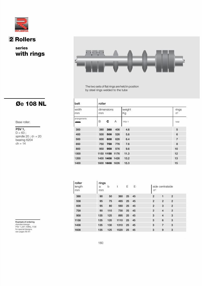
7/27/2019 31801183 Idler Roller
http://slidepdf.com/reader/full/31801183-idler-roller 182/308
180
®
2 Rollers
Base roller:
PSV 1,D = 63 ;spindle 20 ; d 1 = 20bearing 6204ch = 14
Øe 108 NL
serieswith rings
belt roller
width dimensions weight ringsmm mm Kg n o
arrangements
B C A PSV-1 total
300 380 388 406 4.6 5
400 500 508 526 5.6 6
500 600 608 626 6.4 7
650 750 758 776 7.6 8
800 950 958 976 9.6 10
1000 1150 1158 1176 11.3 12
1200 1400 1408 1426 13.2 13
1400 1600 1608 1626 15.3 15
roller ringslength a b t E E 1 side centralsidemm mm n o
388 90 50 360 25 45 2 1 2508 95 75 465 25 45 2 2 2
608 95 80 560 25 45 2 3 2
758 90 110 730 25 45 2 4 2
958 135 125 895 25 45 3 4 3
1158 135 120 1110 25 45 3 6 3
1408 135 130 1310 25 45 3 7 3
1608 135 125 1520 25 45 3 9 3
Example of orderingstandard designPSV 1,20F,108NL,1158for special designssee pages 80-81
The two sets of flat rings are held in positionby steel rings welded to the tube
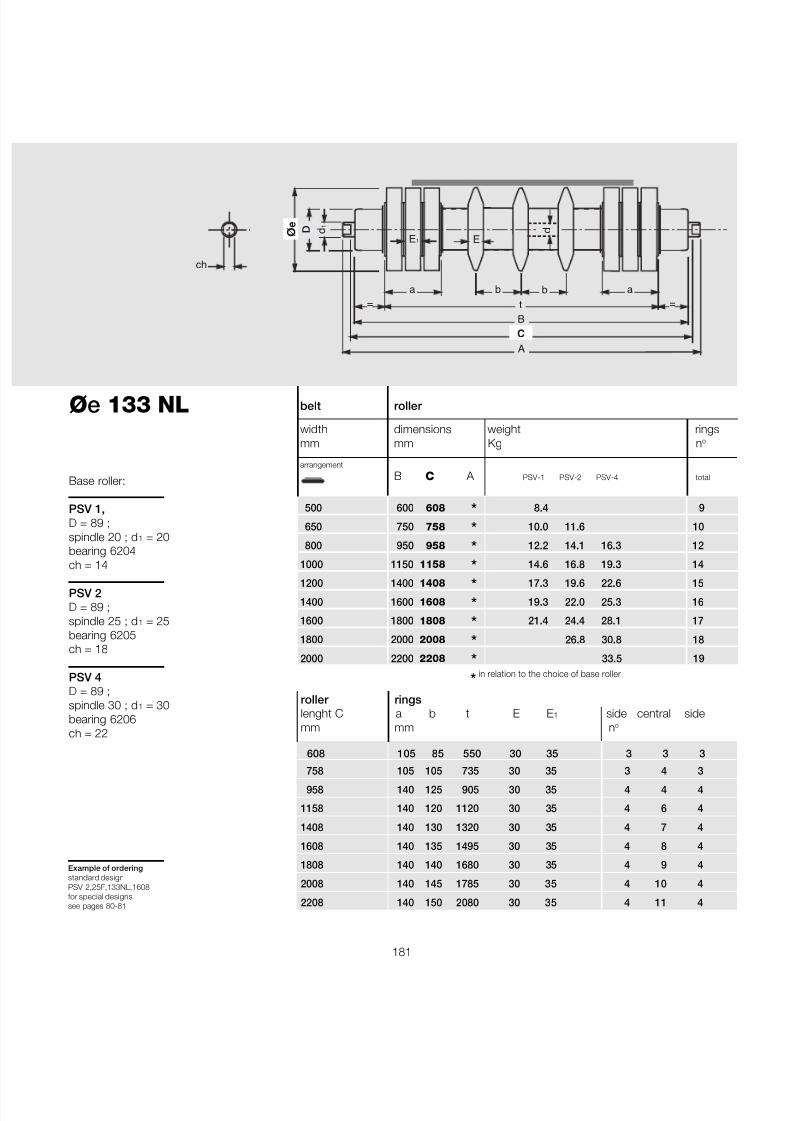
7/27/2019 31801183 Idler Roller
http://slidepdf.com/reader/full/31801183-idler-roller 183/308
181
Base roller:
PSV 1,D = 89 ;spindle 20 ; d 1 = 20bearing 6204ch = 14
PSV 2D = 89 ;spindle 25 ; d 1 = 25bearing 6205ch = 18
PSV 4D = 89 ;spindle 30 ; d 1 = 30bearing 6206ch = 22
Øe 133 NL
B
A
ø e
C
ch
d 1
d D
E
a b b a
= =t
E 1
Example of orderingstandard designPSV 2,25F,133NL,1608for special designssee pages 80-81
roller ringslenght C a b t E E 1 side central sidemm mm n o
608 105 85 550 30 35 3 3 3
758 105 105 735 30 35 3 4 3958 140 125 905 30 35 4 4 4
1158 140 120 1120 30 35 4 6 4
1408 140 130 1320 30 35 4 7 4
1608 140 135 1495 30 35 4 8 4
1808 140 140 1680 30 35 4 9 4
2008 140 145 1785 30 35 4 10 4
2208 140 150 2080 30 35 4 11 4
belt roller
width dimensions weight ringsmm mm Kg n o
arrangement
B C A PSV-1 PSV-2 PSV-4 total
500 600 608 * 8.4 9
650 750 758 * 10.0 11.6 10
800 950 958 * 12.2 14.1 16.3 12
1000 1150 1158 * 14.6 16.8 19.3 14
1200 1400 1408 * 17.3 19.6 22.6 15
1400 1600 1608 * 19.3 22.0 25.3 16
1600 1800 1808 * 21.4 24.4 28.1 17
1800 2000 2008 * 26.8 30.8 18
2000 2200 2208 * 33.5 19 *in relation to the choice of base roller
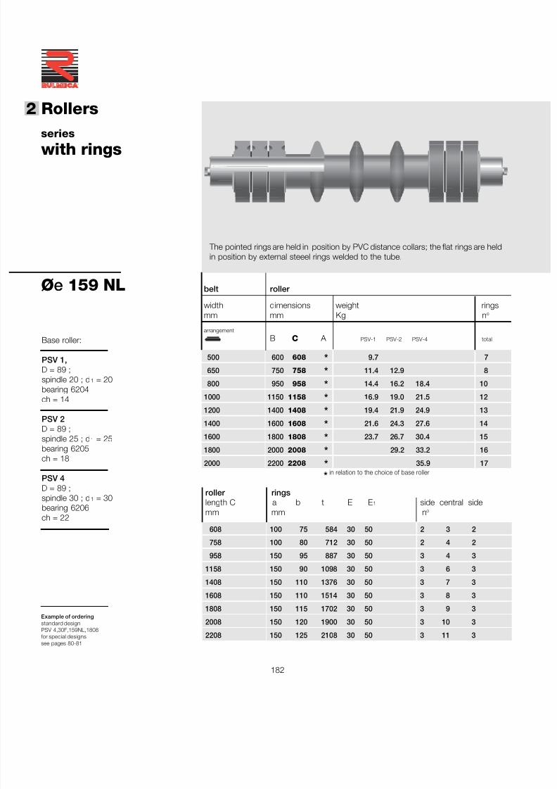
7/27/2019 31801183 Idler Roller
http://slidepdf.com/reader/full/31801183-idler-roller 184/308
182
®
2 Rollers
Øe 159 NL
Example of orderingstandard designPSV 4,30F,159NL,1808for special designssee pages 80-81
Base roller:
PSV 1,D = 89 ;spindle 20 ; d 1 = 20bearing 6204ch = 14
PSV 2D = 89 ;spindle 25 ; d 1 = 25bearing 6205ch = 18
PSV 4D = 89 ;spindle 30 ; d 1 = 30bearing 6206ch = 22
serieswith rings
The pointed rings are held in position by PVC distance collars; the flat rings are heldin position by external steeel rings welded to the tube.
roller ringslength C a b t E E 1 side central sidemm mm n o
608 100 75 584 30 50 2 3 2
758 100 80 712 30 50 2 4 2958 150 95 887 30 50 3 4 3
1158 150 90 1098 30 50 3 6 3
1408 150 110 1376 30 50 3 7 3
1608 150 110 1514 30 50 3 8 3
1808 150 115 1702 30 50 3 9 3
2008 150 120 1900 30 50 3 10 3
2208 150 125 2108 30 50 3 11 3
belt roller
width dimensions weight ringsmm mm Kg n o
arrangement
B C A PSV-1 PSV-2 PSV-4 total
500 600 608 * 9.7 7
650 750 758 * 11.4 12.9 8
800 950 958 * 14.4 16.2 18.4 10
1000 1150 1158 * 16.9 19.0 21.5 12
1200 1400 1408 * 19.4 21.9 24.9 13
1400 1600 1608 * 21.6 24.3 27.6 14
1600 1800 1808 * 23.7 26.7 30.4 15
1800 2000 2008 * 29.2 33.2 16
2000 2200 2208 * 35.9 17 *in relation to the choice of base roller
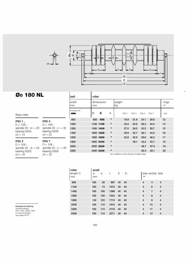
7/27/2019 31801183 Idler Roller
http://slidepdf.com/reader/full/31801183-idler-roller 185/308
183
Øe 180 NL
Example of orderingstandard designPSV 4,30F,180NL,1808for special designssee pages 80-81
Base roller:
PSV 1 ,D = 108 ;spindle 20 ; d 1 = 20bearing 6204ch = 14
PSV 2D = 108 ;spindle 25 ; d 1 = 25bearing 6205ch = 18
PSV 4D = 108 ;spindle 30 ; d 1 = 30bearing 6206ch = 22
PSV 7D = 108 ;spindle 40 ; d 1 = 40bearing 6308ch = 32
B
A
ø e
C
ch
d 1
d D
E
a b b a
= =t
E 1
roller anellilength C a b t E E 1 side central sidemm mm n o
958 160 85 897 40 40 4 4 41158 160 75 1073 40 40 4 6 4
1408 160 100 1386 40 40 4 7 4
1608 160 100 1524 40 40 4 8 4
1808 160 105 1712 40 40 4 9 4
2008 160 110 1910 40 40 4 10 4
2208 160 115 2118 40 40 4 11 4
2408 160 115 2271 40 40 4 12 4
belt roller
width dimensions weight ringsmm mm Kg n o
arrangement
B C A PSV-1 PSV-2 PSV-4 PSV-7 total
800 950 958 * 19.9 21.8 24.1 29.6 12
1000 1150 1158 * 23.5 25.6 28.3 34.5 14
1200 1400 1408 * 27.0 29.5 32.5 39.7 15
1400 1600 1608 * 29.9 32.7 36.1 44.0 16
1600 1800 1808 * 32.8 35.9 39.6 48.3 17
1800 2000 2008 * 39.1 43.2 52.7 18
2000 2200 2208 * 46.7 57.0 19
2200 2400 2408 * 50.3 63.1 20 * in relation to the choice of base roller
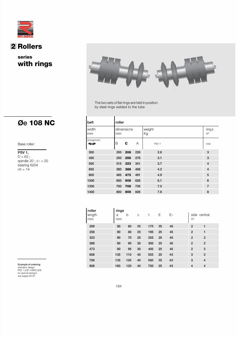
7/27/2019 31801183 Idler Roller
http://slidepdf.com/reader/full/31801183-idler-roller 186/308
184
®
2 Rollers
belt roller
width dimensions weight ringsmm mm Kg n o
arrangement
B C A PSV-1 total
300 200 208 226 2.8 3
400 250 258 276 3.1 3
500 315 323 341 3.7 4
650 380 388 406 4.2 4
800 465 473 491 4.9 5
1000 600 608 626 6.1 6
1200 700 708 726 7.0 7
1400 800 808 826 7.9 8
Øe 108 NC
Example of orderingstandard designPSV 1,20F,108NC,608for special designssee pages 80-81
Base roller:
PSV 1,D = 63 ;spindle 20 ; d 1 = 20bearing 6204ch = 14
serieswith rings
roller ringslength a b c t E E 1 side centralmm mm n o
208 90 60 25 175 25 45 2 1
258 90 80 25 195 25 45 2 1323 90 70 25 255 25 45 2 2
388 90 90 30 300 25 45 2 2
473 90 95 30 405 25 45 2 3
608 135 110 40 505 25 45 3 3
708 135 105 40 595 25 45 3 4
808 180 120 40 700 25 45 4 4
The two sets of flat rings are held in positionby steel rings welded to the tube
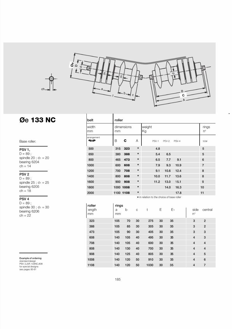
7/27/2019 31801183 Idler Roller
http://slidepdf.com/reader/full/31801183-idler-roller 187/308
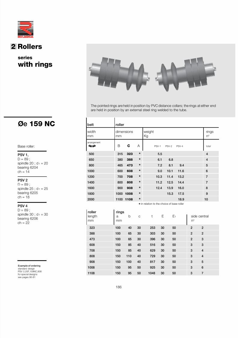
7/27/2019 31801183 Idler Roller
http://slidepdf.com/reader/full/31801183-idler-roller 188/308
186
®
2 Rollers
Øe 159 NC
Example of orderingstandard designPSV 2,25F,159NC,908for special designssee pages 80-81
serieswith rings
roller ringslength a b c t E E 1 side centralmm mm n o
323 100 40 30 253 30 50 2 2
388 100 65 30 303 30 50 2 2
473 100 65 30 396 30 50 2 3
608 150 85 40 516 30 50 3 3
708 150 85 40 629 30 50 3 4
808 150 110 40 729 30 50 3 4
908 150 100 40 817 30 50 3 5
1008 150 95 50 925 30 50 3 6
1108 150 95 50 1048 30 50 3 7
Base roller:
PSV 1,D = 89 ;spindle 20 ; d 1 = 20bearing 6204ch = 14
PSV 2D = 89 ;spindle 25 ; d 1 = 25bearing 6205ch = 18
PSV 4D = 89 ;spindle 30 ; d 1 = 30bearing 6206ch = 22
belt roller
width dimensions weight ringsmm mm Kg n o
arrangement
B C A PSV-1 PSV-2 PSV-4 total
500 315 323 * 5.5 4
650 380 388 * 6.1 6.8 4
800 465 473 * 7.2 8.1 9.4 5
1000 600 608 * 9.0 10.1 11.6 6
1200 700 708 * 10.3 11.4 13.2 7
1400 800 808 * 11.2 12.5 14.4 7
1600 900 908 * 12.4 13.9 16.0 8
1800 1000 1008 * 15.3 17.5 9
2000 1100 1108 * 18.9 10 * in relation to the choice of base roller
The pointed rings are held in position by PVC distance collars; the rings at either endare held in position by an external steel ring welded to the tube.
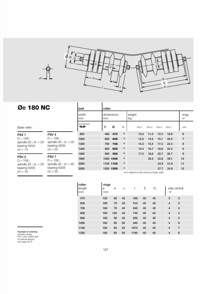
7/27/2019 31801183 Idler Roller
http://slidepdf.com/reader/full/31801183-idler-roller 189/308
187
Øe 180 NC
Example of orderingstandard designPSV 2,25F,180NC,908for special designssee pages 80-81
roller ringslength a b c t E E 1 side centralmm mm n o
473 120 60 45 435 40 40 3 3
608 160 70 45 515 40 40 4 3
708 160 75 45 645 40 40 4 4
808 160 100 45 745 40 40 4 4
908 160 90 45 835 40 40 4 5
1008 160 85 55 945 40 40 4 6
1108 160 85 55 1070 40 40 4 7
1258 160 85 55 1195 40 40 4 8
belt roller
width dimensions weight ringsmm mm Kg n o
arrangement
B C A PSV-1 PSV-2 PSV-4 PSV-7 total
800 465 473 * 10.2 11.0 12.4 16.8 6
1000 600 608 * 12.5 13.5 15.1 20.0 7
1200 700 708 * 14.2 15.4 17.2 22.4 8
1400 800 808 * 15.4 16.7 18.6 24.3 8
1600 900 908 * 17.2 18.6 20.7 26.7 9
1800 1000 1008 * 20.5 22.8 29.1 10
2000 1100 1108 * 24.9 31.6 11
2200 1250 1258 * 27.7 34.9 12 * in relation to the choice of base roller
ch B
A
C
d
ø e
d 1 D
E
a
b
t
E 1
c
Base roller:
PSV 1D = 108 ;spindle 20 ; d 1 = 20bearing 6204ch = 14
PSV 2D = 108 ;spindle 25 ; d 1 = 25bearing 6205ch = 18
PSV 4D = 108 ;spindle 30 ; d 1 = 30bearing 6206ch = 22
PSV 7D = 108 ;spindle 40 ; d 1 = 40bearing 6308ch = 32
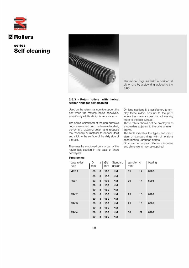
7/27/2019 31801183 Idler Roller
http://slidepdf.com/reader/full/31801183-idler-roller 190/308
188
®
2 Rollers
2.6.3 - Return rollers with helicalrubber rings for self cleaning
Used on the return transom to support thebelt when the material being conveyed,even if only a little sticky, is very viscous.
The helical spiral form of the non-abrasiverings, assembled onto the base roller shell,performs a cleaning action and reducesthe tendency of material to deposit itself and stick to the surface of the dirty side of the belt.
They may be employed on any part of thereturn belt section in the case of shortconveyors.
seriesSelf cleaning
On long sections it is satisfactory to em-ploy these rollers only up to the pointwhere the material does not adhere anymore to the belt surface.
These rollers should not be employed assnub rollers adjacent to the drive or returndrums.
The table indicates the types and diam-eters of standard rings with dimensionsaccording to European norms.On customer request different diametersand dimensions may be supplied.
The rubber rings are held in position ateither end by a steel ring welded to thetube.
Programme
base roller D s ø e Standard spindle ch bearingtype mm mm design mm
MPS 1 60 3 108 NM 15 17 6202
89 3 133 NM
PSV 1 63 3 108 NM 20 14 6204
89 3 133 NM
89 3 180 NM
PSV 2 89 3 133 NM 25 18 6205
89 3 180 NM
PSV 3 89 3 133 NM 25 18 6305
89 3 180 NM
PSV 4 89 3 133 NM 30 22 6206
89 3 180 NM
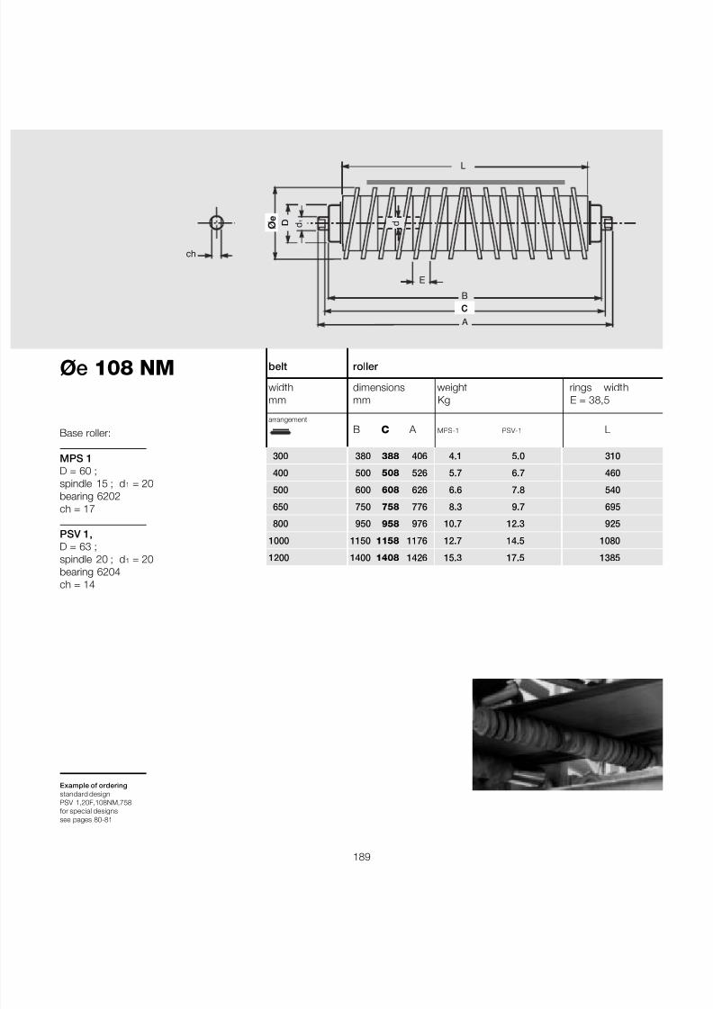
7/27/2019 31801183 Idler Roller
http://slidepdf.com/reader/full/31801183-idler-roller 191/308
189
Øe 108 NM
Example of orderingstandard designPSV 1,20F,108NM,758for special designssee pages 80-81
belt roller
width dimensions weight rings widthmm mm Kg E = 38,5
arrangement
B C A MPS-1 PSV-1 L
300 380 388 406 4.1 5.0 310
400 500 508 526 5.7 6.7 460
500 600 608 626 6.6 7.8 540
650 750 758 776 8.3 9.7 695
800 950 958 976 10.7 12.3 925
1000 1150 1158 1176 12.7 14.5 1080
1200 1400 1408 1426 15.3 17.5 1385
Base roller:
MPS 1D = 60 ;spindle 15 ; d 1 = 20bearing 6202ch = 17
PSV 1,D = 63 ;spindle 20 ; d 1 = 20bearing 6204ch = 14
B
A
ø e
C
ch
d 1 D
E
d
L
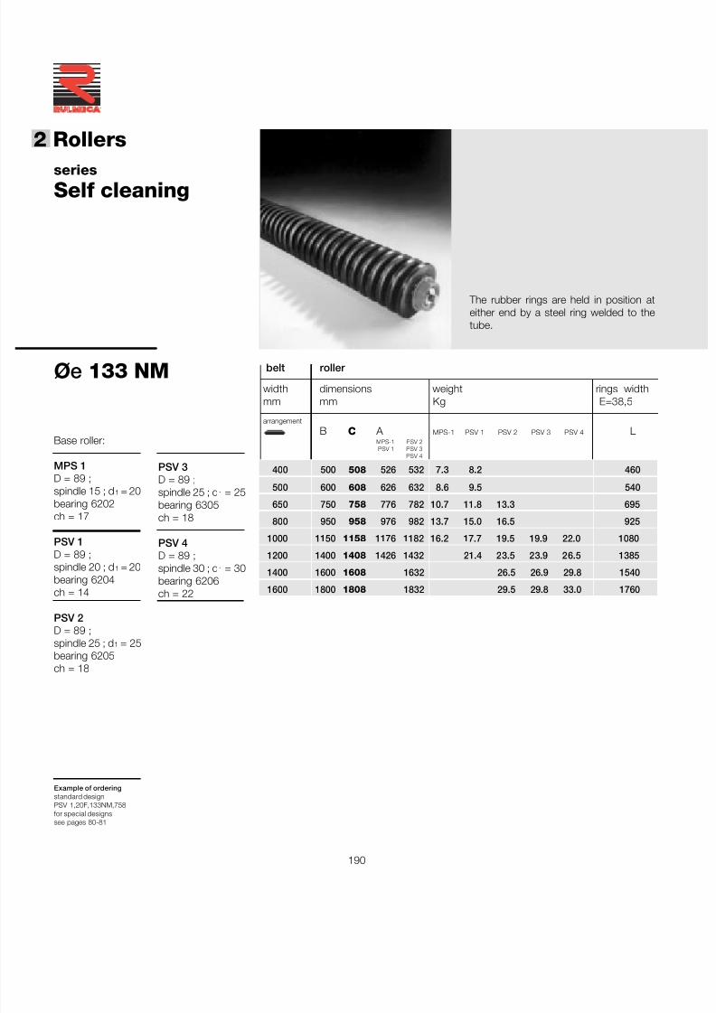
7/27/2019 31801183 Idler Roller
http://slidepdf.com/reader/full/31801183-idler-roller 192/308
190
®
2 Rollers
Øe 133 NM
Example of orderingstandard designPSV 1,20F,133NM,758for special designssee pages 80-81
seriesSelf cleaning
belt roller
width dimensions weight rings widthmm mm Kg E=38,5
arrangement
B C A MPS-1 PSV 1 PSV 2 PSV 3 PSV 4 LMPS-1 PSV 2PSV 1 PSV 3
PSV 4
400 500 508 526 532 7.3 8.2 460
500 600 608 626 632 8.6 9.5 540
650 750 758 776 782 10.7 11.8 13.3 695
800 950 958 976 982 13.7 15.0 16.5 9251000 1150 1158 1176 1182 16.2 17.7 19.5 19.9 22.0 1080
1200 1400 1408 1426 1432 21.4 23.5 23.9 26.5 1385
1400 1600 1608 1632 26.5 26.9 29.8 1540
1600 1800 1808 1832 29.5 29.8 33.0 1760
PSV 3D = 89 ;spindle 25 ; d 1 = 25bearing 6305
ch = 18
PSV 4D = 89 ;spindle 30 ; d 1 = 30bearing 6206ch = 22
Base roller:
MPS 1D = 89 ;spindle 15 ; d 1 = 20bearing 6202ch = 17
PSV 1D = 89 ;spindle 20 ; d 1 = 20bearing 6204ch = 14
PSV 2D = 89 ;spindle 25 ; d 1 = 25bearing 6205ch = 18
The rubber rings are held in position ateither end by a steel ring welded to thetube.
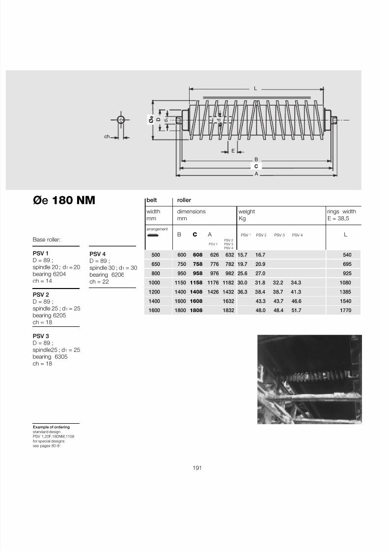
7/27/2019 31801183 Idler Roller
http://slidepdf.com/reader/full/31801183-idler-roller 193/308
191
Øe 180 NM
Example of orderingstandard designPSV 1,20F,180NM,1158for special designssee pages 80-81
B
A
ø e
C
ch
d 1 D
E
d
L
PSV 4D = 89 ;spindle 30 ; d 1 = 30bearing 6206
ch = 22
Base roller:
PSV 1D = 89 ;spindle 20 ; d 1 = 20bearing 6204ch = 14
PSV 2D = 89 ;spindle 25 ; d 1 = 25bearing 6205ch = 18
PSV 3D = 89 ;spindle25 ; d 1 = 25bearing 6305ch = 18
belt roller
width dimensions weight rings widthmm mm Kg E = 38,5
arrangement
B C A PSV 1 PSV 2 PSV 3 PSV 4 LPSV 2
PSV 1 PSV 3PSV 4
500 600 608 626 632 15.7 16.7 540
650 750 758 776 782 19.7 20.9 695
800 950 958 976 982 25.6 27.0 925
1000 1150 1158 1176 1182 30.0 31.8 32.2 34.3 10801200 1400 1408 1426 1432 36.3 38.4 38.7 41.3 1385
1400 1600 1608 1632 43.3 43.7 46.6 1540
1600 1800 1808 1832 48.0 48.4 51.7 1770
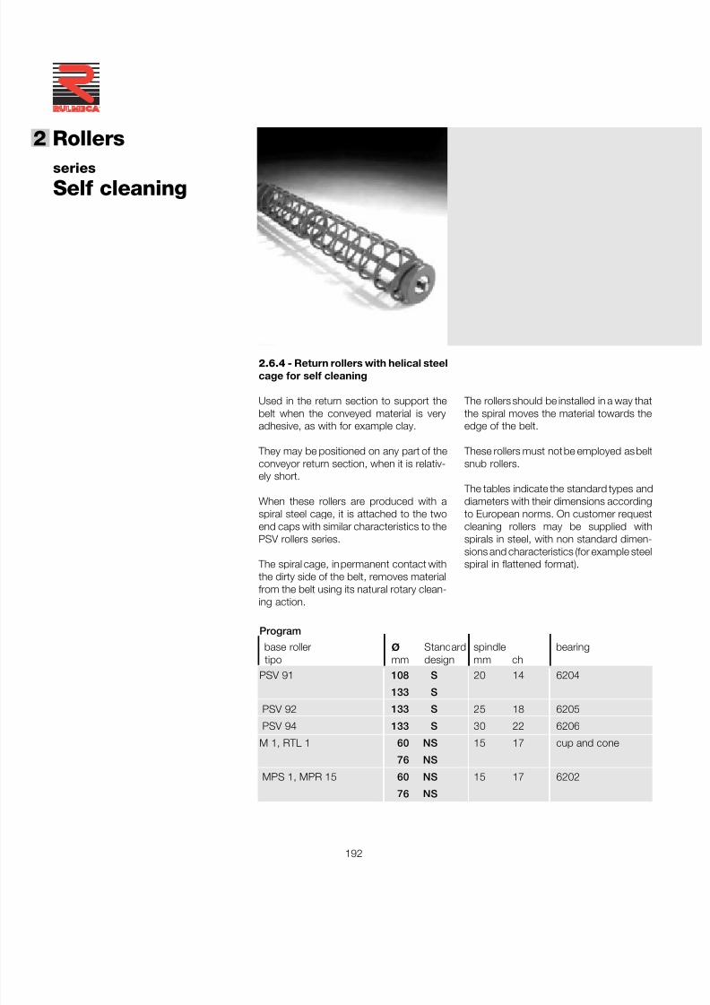
7/27/2019 31801183 Idler Roller
http://slidepdf.com/reader/full/31801183-idler-roller 194/308
192
®
2 Rollers
seriesSelf cleaning
The rollers should be installed in a way thatthe spiral moves the material towards theedge of the belt.
These rollers must not be employed as beltsnub rollers.
The tables indicate the standard types anddiameters with their dimensions according
to European norms. On customer requestcleaning rollers may be supplied withspirals in steel, with non standard dimen-sions and characteristics (for example steelspiral in flattened format).
2.6.4 - Return rollers with helical steelcage for self cleaning
Used in the return section to support thebelt when the conveyed material is veryadhesive, as with for example clay.
They may be positioned on any part of theconveyor return section, when it is relativ-ely short.
When these rollers are produced with a
spiral steel cage, it is attached to the twoend caps with similar characteristics to thePSV rollers series.
The spiral cage, in permanent contact withthe dirty side of the belt, removes materialfrom the belt using its natural rotary clean-ing action.
Program
base roller ø Standard spindle bearing tipo mm design mm chPSV 91 108 S 20 14 6204
133 SPSV 92 133 S 25 18 6205
PSV 94 133 S 30 22 6206
M 1, RTL 1 60 NS 15 17 cup and cone
76 NS
MPS 1, MPR 15 60 NS 15 17 6202
76 NS
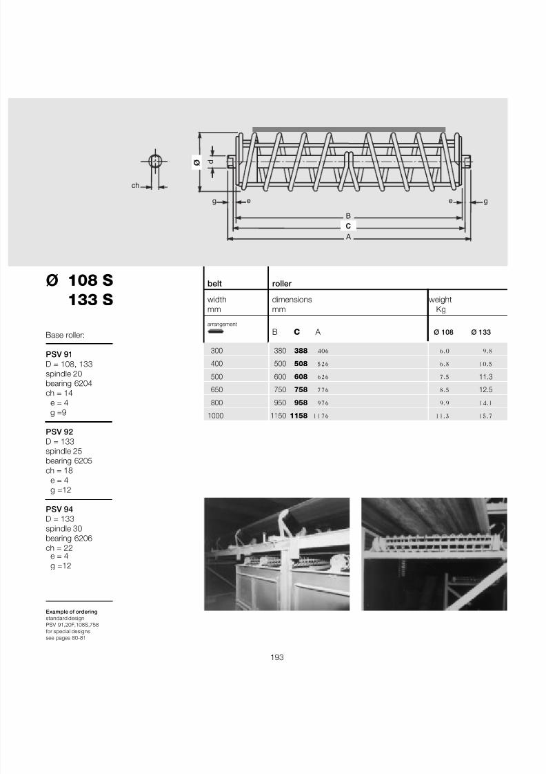
7/27/2019 31801183 Idler Roller
http://slidepdf.com/reader/full/31801183-idler-roller 195/308
193
Ø 108 S 133 S
e = 4g =12
Example of orderingstandard designPSV 91,20F,108S,758for special designssee pages 80-81
B
A
ø
C
g g
ch
d
e e
belt roller
width dimensions weightmm mm Kg
arrangement
B C A Ø 108 Ø 133
300 380 388 406 6.0 9.8
400 500 508 526 6.8 10.5
500 600 608 626 7.5 11.3
650 750 758 776 8.5 12.5
800 950 958 976 9.9 14.1
1000 1150 1158 1176 11.3 15.7
Base roller:
PSV 91D = 108, 133spindle 20bearing 6204ch = 14
e = 4g =9
PSV 92D = 133spindle 25bearing 6205ch = 18
e = 4g =12
PSV 94D = 133
spindle 30bearing 6206ch = 22
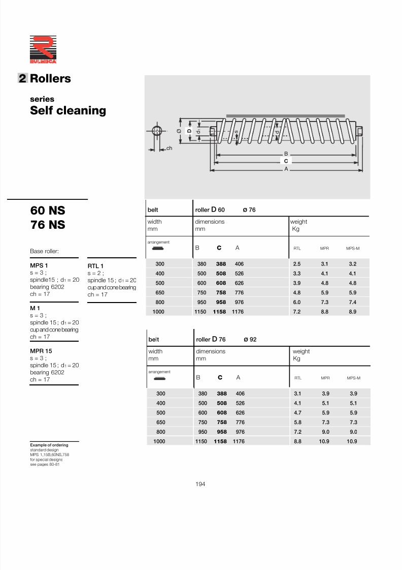
7/27/2019 31801183 Idler Roller
http://slidepdf.com/reader/full/31801183-idler-roller 196/308
194
®
2 Rollers
60 NS76 NS
Example of orderingstandard designMPS 1,15B,60NS,758for special designssee pages 80-81
seriesSelf cleaning
belt roller D 60 ø 76
width dimensions weightmm mm Kg
arrangement
B C A RTL MPR MPS-M
300 380 388 406 2.5 3.1 3.2
400 500 508 526 3.3 4.1 4.1
500 600 608 626 3.9 4.8 4.8
650 750 758 776 4.8 5.9 5.9800 950 958 976 6.0 7.3 7.4
1000 1150 1158 1176 7.2 8.8 8.9
Base roller:
MPS 1s = 3 ;spindle15 ; d 1 = 20bearing 6202
ch = 17
M 1s = 3 ;spindle 15 ; d 1 = 20cup and cone bearingch = 17
MPR 15s = 3 ;spindle 15 ; d 1 = 20bearing 6202ch = 17
B
Ø
C
ch
d 1
A
d D s
belt roller D 76 ø 92
width dimensions weightmm mm Kg
arrangement
B C A RTL MPR MPS-M
300 380 388 406 3.1 3.9 3.9
400 500 508 526 4.1 5.1 5.1
500 600 608 626 4.7 5.9 5.9
650 750 758 776 5.8 7.3 7.3
800 950 958 976 7.2 9.0 9.0
1000 1150 1158 1176 8.8 10.9 10.9
RTL 1s = 2 ;spindle 15 ; d 1 = 20cup and cone bearing
ch = 17
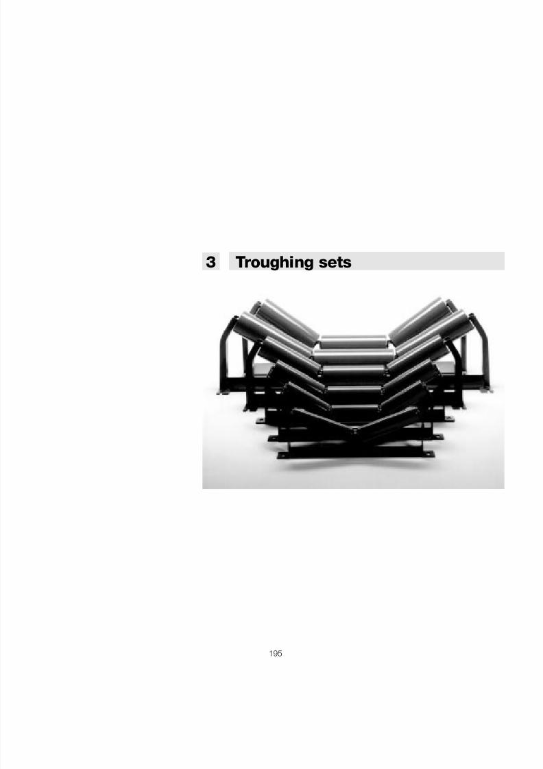
7/27/2019 31801183 Idler Roller
http://slidepdf.com/reader/full/31801183-idler-roller 197/308
195
3 Troughing sets
7/27/2019 31801183 Idler Roller
http://slidepdf.com/reader/full/31801183-idler-roller 198/308
196
®
3 Troughing
sets
Summary 3 Troughing sets page195
3.1 Introduction ...............................................................197
3.2 Choice of troughing set ........................................ 1983.2.1 Choice of the transom in relation to load .......................200
3.3 Arrangements ........................................................... 2023.3.1 Carrying troughing sets ................................................ 2023.3.2 Return sets ................................................................. 2033.3.3 Order codes .............................................................. 2043.3.4 Programme of transoms and bracketry ........................ 205
3.4 Self-centralising troughing sets .......................... 222
3.5 Cantilevered sets .................................................... 234
3.6 Suspended sets ....................................................... 2393.6.1 Characteristics ............................................................ 2403.6.2 Applications and arrangements .................................... 2413.6.3 Programme ................................................................. 2433.6.4 Suspension designs ..................................................... 250
7/27/2019 31801183 Idler Roller
http://slidepdf.com/reader/full/31801183-idler-roller 199/308
197
3.1 - Introduction
In a belt conveyor one may identify twotypes of troughing sets : the upper carryingsets, that have the function to support theloaded sections of the belt and to move thematerial ; and the lower sets that supportthe unloaded belt on its return section.
The upper troughing sets may basically bein two arrangements : flat, with a singlehorizontal roller generally supported by twofixed brackets from the convey orstructure ; troughed, generally with 3rollers supported within a frame which isitself fixed to the conveyor structure.
There may be then, in the loaded sections,impact troughing sets with rollers withrubber rings or suspended “garland” setswith 3 or 5 rollers.
In the majority of belt conveyors, the uppertroughing sets are used in a troughingarrangement, so that the carrying belt maytransport a much greater amount of mater-ial than it could if the belt was flat, assumingan equal belt width and speed.
The rollers of an upper troughing set areundoubtedly the most important compon-ents to be considered during the projectphase.
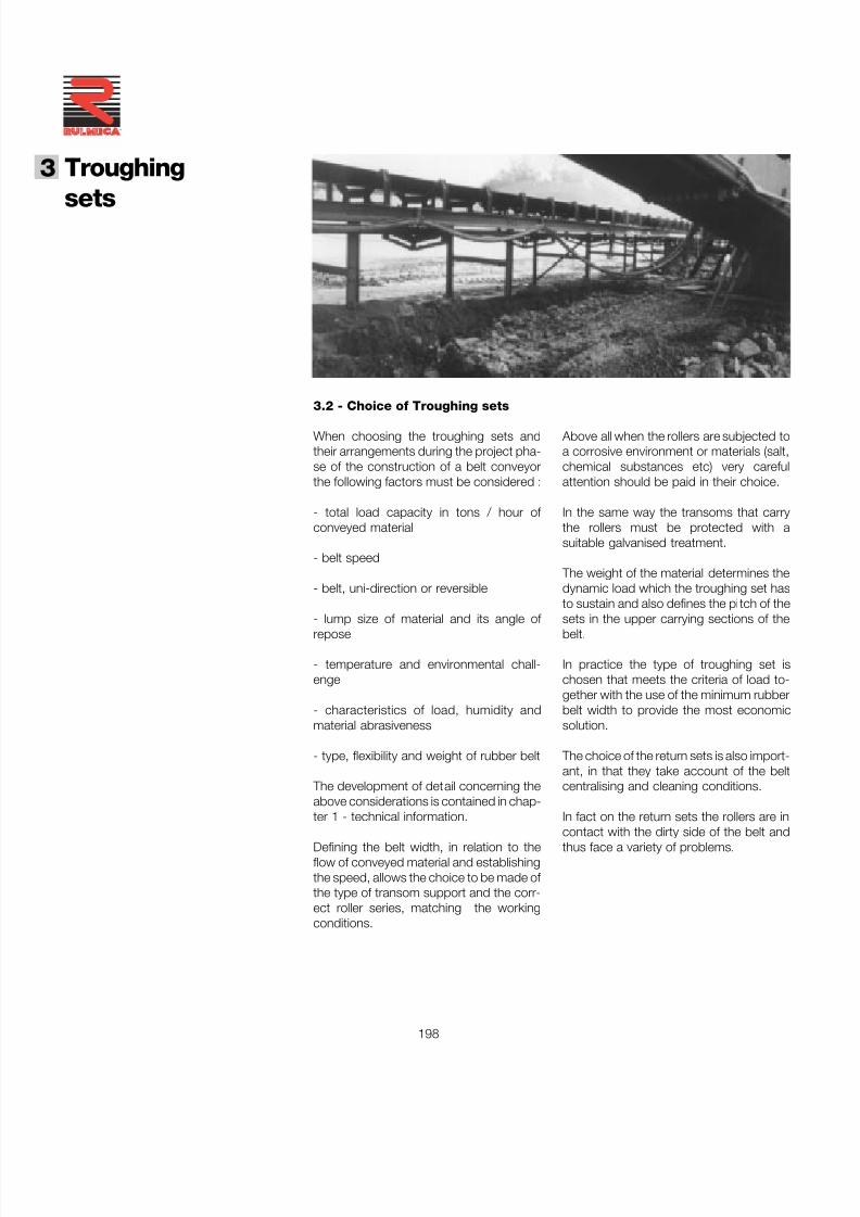
7/27/2019 31801183 Idler Roller
http://slidepdf.com/reader/full/31801183-idler-roller 200/308
198
®
3 Troughing
sets
3.2 - Choice of Troughing sets
When choosing the troughing sets andtheir arrangements during the project pha-se of the construction of a belt conveyorthe following factors must be considered :
- total load capacity in tons / hour of conveyed material
- belt speed
- belt, uni-direction or reversible
- lump size of material and its angle of repose
- temperature and environmental chall-enge
- characteristics of load, humidity andmaterial abrasiveness
- type, flexibility and weight of rubber belt
The development of detail concerning theabove considerations is contained in chap-ter 1 - technical information.
Defining the belt width, in relation to theflow of conveyed material and establishingthe speed, allows the choice to be made of the type of transom support and the corr-ect roller series, matching the workingconditions.
Above all when the rollers are subjected toa corrosive environment or materials (salt,chemical substances etc) very carefulattention should be paid in their choice.
In the same way the transoms that carrythe rollers must be protected with asuitable galvanised treatment.
The weight of the material determines thedynamic load which the troughing set hasto sustain and also defines the pitch of thesets in the upper carrying sections of thebelt.
In practice the type of troughing set ischosen that meets the criteria of load to-gether with the use of the minimum rubberbelt width to provide the most economicsolution.
The choice of the return sets is also import-ant, in that they take account of the beltcentralising and cleaning conditions.
In fact on the return sets the rollers are in
contact with the dirty side of the belt andthus face a variety of problems.
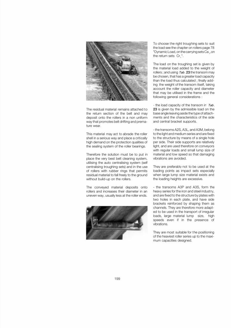
7/27/2019 31801183 Idler Roller
http://slidepdf.com/reader/full/31801183-idler-roller 201/308
199
The residual material remains attached tothe return section of the belt and maydeposit onto the rollers in a non uniformway that promotes belt drifting and prema-ture wear.
This material may act to abrade the rollershell in a serious way and place a crit icallyhigh demand on the protection qualities of the sealing system of the roller bearings.
Therefore the solution must be to put inplace the very best belt cleaning system,utilising the auto centralising system (self centralising troughing sets) and in the useof rollers with rubber rings that permitsresidual material to fall freely to the groundwithout build-up on the rollers.
The conveyed material deposits ontorollers and increases their diameter in anuneven way, usually less at the roller ends.
To choose the right troughing sets to suitthe load see the chapter on rollers page 78"Dynamic Load, on the carrying sets Ca 1,o
the return sets Cr 1".
The load on the troughing set is given bythe material load added to the weight of rollers ; and using Tab . 23 the transom maybe chosen, that has a greater load capacitythan the load thus calculated ; finally add-ing the weight of the transom itself, takingaccount the roller capacity and diameterthat may be utilised in the frame and thefollowing general considerations :
- the load capacity of the transom in Tab23 is given by the admissible load on thebase angle leaving aside the type of attach-ments and the characteristics of the sideand central bracket supports.
- the transoms A2S, A3L, and A3M, belongto the light and medium series and are fixedto the structure by means of a single holeper side. Their side supports are relativelylight, and are used therefore on conveyorswith regular loads and small lump size of material and low speed so that damagingvibrations are avoided.
They are preferably not to be used at theloading points as impact sets especiallywhen large lump size material exists andthe loading heights are excessive.
- the transoms A3P and A3S, form theheavy series for the iron and steel industry,and are fixed to the structure by plates withtwo holes in each plate, and have sidebrackets reinforced by shaping them aschannels. They are therefore more adapt-ed to be used in the transport of irregularloads, large material lump size, highspeeds even if in the presence of
vibrations.
They are most suitable for the positioningof the heaviest roller series up to the maxi-mum capacities designed.
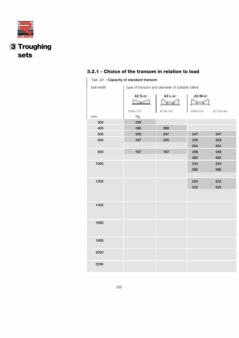
7/27/2019 31801183 Idler Roller
http://slidepdf.com/reader/full/31801183-idler-roller 202/308
200
®
3 Troughing
sets3.2.1 - Choice of the transom in relation to load
Tab. 23 - Capacity of standard transom
belt width type of transom and diameter of suitable rollers
A2 S -20 ° A3 L -30 ° A3 M -30 °
Ø 60 ÷ 110 Ø 76 ÷ 110 Ø 89 ÷ 110 Ø 110
mm Kg300 338
400 286 286
500 205 247 247 247
650 167 205 205 205
354 354
800 167 167 289 289
460 460
1000 244 244
388 388
1200 204 204
325 325
1400
1600
1800
2000
2200
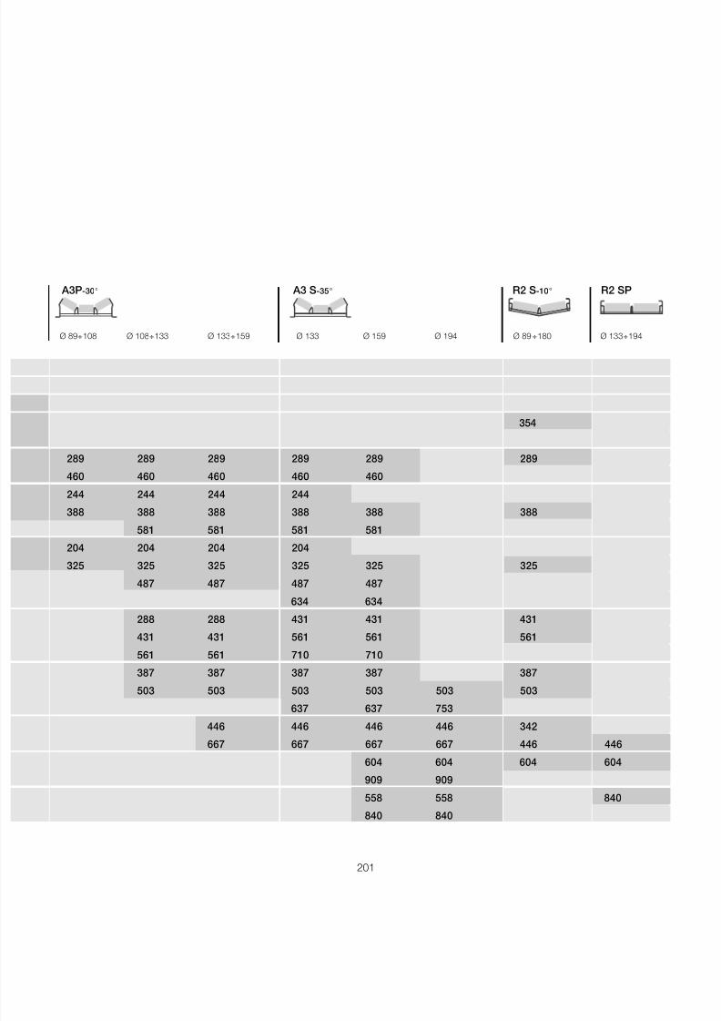
7/27/2019 31801183 Idler Roller
http://slidepdf.com/reader/full/31801183-idler-roller 203/308
201
A3P -30 ° A3 S -35 ° R2 S -10 ° R2 SP
Ø 89 ÷ 108 Ø 108 ÷ 133 Ø 133 ÷ 159 Ø 133 Ø 159 Ø 194 Ø 89 ÷ 180 Ø 133 ÷ 194
354
289 289 289 289 289 289
460 460 460 460 460
244 244 244 244
388 388 388 388 388 388
581 581 581 581
204 204 204 204
325 325 325 325 325 325
487 487 487 487
634 634
288 288 431 431 431
431 431 561 561 561
561 561 710 710
387 387 387 387 387
503 503 503 503 503 503
637 637 753
446 446 446 446 342
667 667 667 667 446 446
604 604 604 604
909 909
558 558 840
840 840
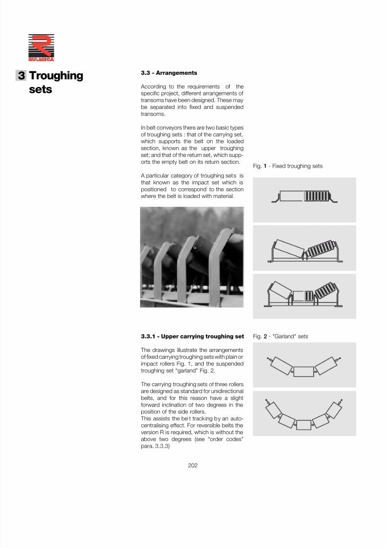
7/27/2019 31801183 Idler Roller
http://slidepdf.com/reader/full/31801183-idler-roller 204/308
202
®
3 Troughing
sets
3.3 - Arrangements
According to the requirements of the
specific project, different arrangements of transoms have been designed. These maybe separated into fixed and suspendedtransoms.
In belt conveyors there are two basic typesof troughing sets : that of the carrying set,which supports the belt on the loadedsection, known as the upper troughingset; and that of the return set, which supp-orts the empty belt on its return section.
A particular category of troughing sets isthat known as the impact set which ispositioned to correspond to the sectionwhere the belt is loaded with material.
Fig. 2 - "Garland" sets
Fig. 1 - Fixed troughing sets
3.3.1 - Upper carrying troughing set
The drawings illustrate the arrangementsof fixed carrying troughing sets with plain orimpact rollers Fig. 1, and the suspendedtroughing set “garland” Fig. 2.
The carrying troughing sets of three rollersare designed as standard for unidirectionalbelts, and for this reason have a slightforward inclination of two degrees in theposition of the side rollers.
This assists the belt tracking by an auto-centralising effect. For reversible belts theversion R is required, which is without theabove two degrees (see “order codes”para. 3.3.3)
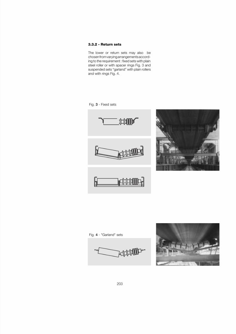
7/27/2019 31801183 Idler Roller
http://slidepdf.com/reader/full/31801183-idler-roller 205/308
203
Fig. 4 - "Garland" sets
3.3.2 - Return sets
The lower or return sets may also be
chosen from varying arrangements accord-ing to the requirement : fixed sets with plainsteel roller or with spacer rings Fig. 3 andsuspended sets “garland” with plain rollersand with rings Fig. 4.
Fig. 3 - Fixed sets
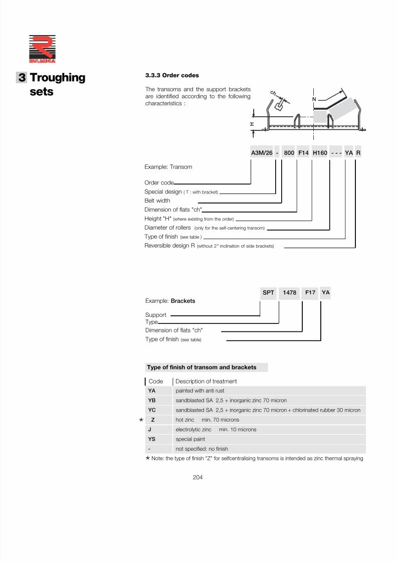
7/27/2019 31801183 Idler Roller
http://slidepdf.com/reader/full/31801183-idler-roller 206/308
204
®
3 Troughing
sets
3.3.3 Order codes
The transoms and the support brackets
are identified according to the followingcharacteristics :
YA painted with anti rust
YB sandblasted SA 2,5 + inorganic zinc 70 micron
YC sandblasted SA 2,5 + inorganic zinc 70 micron + chlorinated rubber 30 micron
Z hot zinc min. 70 microns
J electrolytic zinc min. 10 microns
YS special paint
- not specified: no finish
*Note: the type of finish "Z" for selfcentralising transoms is intended as zinc thermal spraying
SPT 1478 F17 YA Example: Brackets
Support TypeDimension of flats "ch"
Type of finish (see table)
Type of finish of transom and brackets
Code Description of treatment
A3M/26 - 800 F14 H160 - - - YA R
Order code
Special design ( T : with bracket)Belt width
Dimension of flats "ch"
Height "H" (where existing from the order)
Diameter of rollers (only for the self-centering transom)
Type of finish (see table )
Reversible design R (without 2 ° inclination of side brackets)
Example: Transom
H
N
c h
*
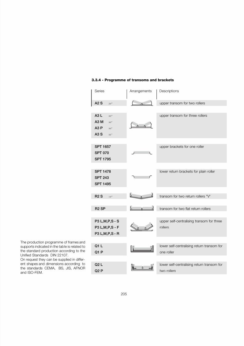
7/27/2019 31801183 Idler Roller
http://slidepdf.com/reader/full/31801183-idler-roller 207/308
205
3.3.4 - Programme of transoms and brackets
Series Arrangements Descriptions
A2 S 20 ° upper transom for two rollers
A3 L 30 ° upper transom for three rollers
A3 M 30 °
A3 P 30 °
A3 S 35 °
SPT 1657 upper brackets for one roller
SPT 070
SPT 1795
SPT 1478 lower return brackets for plain roller
SPT 243 SPT 1495
R2 S 10 ° transom for two return rollers "V"
R2 SP transom for two flat return rollers
P3 L,M,P,S - S upper self-centralising transom for three
P3 L,M,P,S - F rollers
P3 L,M,P,S - R
Q1 L lower self-centralising return transom for
Q1 P one roller
Q2 L lower self-centralising return transom for
Q2 P two rollers
The production programme of frames andsupports indicated in the table is related tothe standard production according to theUnified Standards DIN 22107.On request they can be supplied in differ-ent shapes and dimensions according tothe standards CEMA, BS, JIS, AFNORand ISO-FEM.
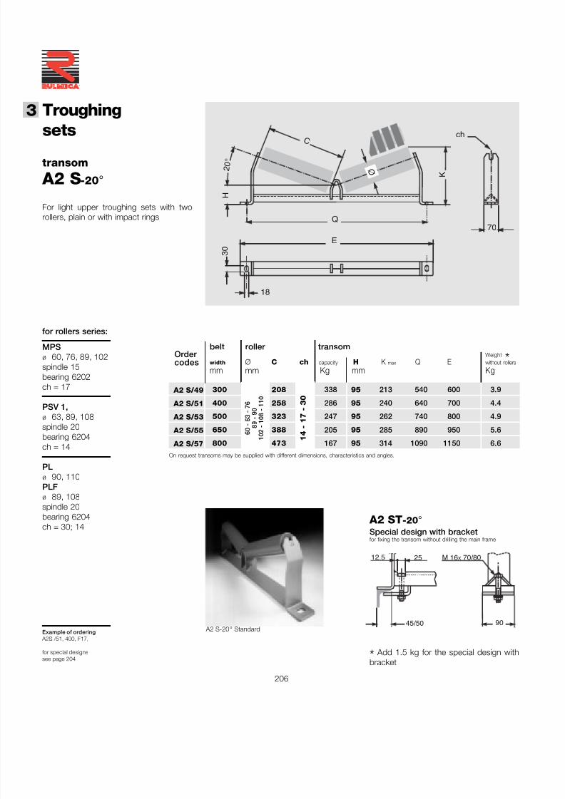
7/27/2019 31801183 Idler Roller
http://slidepdf.com/reader/full/31801183-idler-roller 208/308
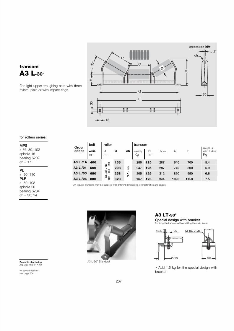
7/27/2019 31801183 Idler Roller
http://slidepdf.com/reader/full/31801183-idler-roller 209/308
207
For light upper troughing sets with threerollers, plain or with impact rings
for rollers series:
ch
70Q
3 0
°
H
KØ
C
2
E 3 0
18
C
Belt direction
A3 LT -30 °
Special design with bracketfor fixing the transom without drilling the main frame
MPSø 76, 89, 102spindle 15bearing 6202ch = 17
PLø 90, 110PLFø 89, 108spindle 20bearing 6204ch = 30; 14
Example of ordering A3L /03, 650, F17, YA
for special designssee page 204
belt roller transomWeight *width Ø C ch capacity H K max Q E without roller
mm mm Kg mm Kg
400 168 286 125 267 640 700 5.4
500 208 247 125 287 740 800 5.9
650 258 205 125 312 890 950 6.6
800 323 167 125 344 1090 1150 7.576 - 89
- 90
102 - 108 - 110
17 - 30
transom
A3 L -30 °
A3 L-30 ° Standard
A3 L /1A
A3 L /01
A3 L /03
A3 L /05
Order codes
On request transoms may be supplied with different dimensions, characteristics and angles.
90
M 16 X 70/80
45/50
2512.5
* Add 1.5 kg for the special design withbracket
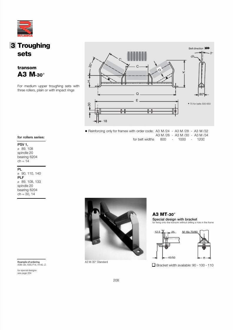
7/27/2019 31801183 Idler Roller
http://slidepdf.com/reader/full/31801183-idler-roller 210/308
208
®
3 Troughing
setstransom
A3 M -30 °
Example of ordering A3M /28 ,1000, F14, H140, Z
for special designssee page 204
for rollers series:
ch
80 *
C
Q
3 0
°
H
KØ
C
2 °
E 3 0
18
Belt direction
A3 MT -30 °
Special design with bracketfor fixing onto the transom without drilling a hole in the frame
PSV 1,ø 89, 108spindle 20bearing 6204ch = 14
PLø 90, 110, 140PLFø 89, 108, 133spindle 20bearing 6204ch = 30, 14
For medium upper troughing sets withthree rollers, plain or with impact rings
*70 for belts 500-650
• Reinforcing only for frames with order code: A3 M /24 - A3 M /28 - A3 M /32A3 M /26 - A3 M /30 - A3 M /34
for belt widths 800 - 1000 - 1200
A3 M-30 ° Standard
• •
M 16 X 70/80
45/50
2512.5
Bracket width available: 90 - 100 - 110
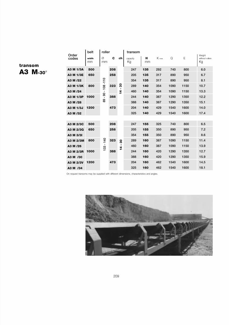
7/27/2019 31801183 Idler Roller
http://slidepdf.com/reader/full/31801183-idler-roller 211/308
209
belt roller transomWeight
width Ø C ch capacity H K max Q E without roller
mm mm Kg mm Kg
500 208 247 135 292 740 800 6.0
650 258 205 135 317 890 950 6.7
354 135 317 890 950 8.1
800 323 289 140 354 1090 1150 10.7
460 140 354 1090 1150 13.3
1000 388 244 140 387 1290 1350 12.2
388 140 387 1290 1350 15.1
1200 473 204 140 429 1540 1600 14.0
325 140 429 1540 1600 17.4
500 208 247 155 325 740 800 6.5
650 258 205 155 350 890 950 7.2
354 155 350 890 950 8.6
800 323 289 160 387 1090 1150 11.4
460 160 387 1090 1150 13.9
1000 388 244 160 420 1290 1350 12.7
388 160 420 1290 1350 15.9
1200 473 204 160 462 1540 1600 14.5
325 160 462 1540 1600 18.1
14 - 30
transom
A3 M -30 ° A3 M 1/3A
A3 M 1/3E
A3 M /22
A3 M 1/3K
A3 M /24
A3 M 1/3P
A3 M /28
A3 M 1/3J
A3 M /32
A3 M 2/3C
A3 M 2/3G
A3 M 3/3I
A3 M 2/3M
A3 M /26
A3 M 2/3R
A3 M /30
A3 M 2/3V
A3 M /34
Order codes
89 - 90 - 108 -110
133 - 140
14 - 30
On request transoms may be supplied with different dimensions, characteristics and angles.
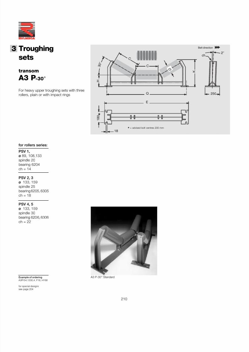
7/27/2019 31801183 Idler Roller
http://slidepdf.com/reader/full/31801183-idler-roller 212/308
210
®
3 Troughing
setstransom
A3 P -30 °
Example of ordering A3P/54,1200,4, F18, H168
for special designssee page 204
for rollers series:
ch
250
C
Q
E
3 0
°
H
KØ
C
2 °
1 8 0
18
Belt direction
PSV 1,ø 89, 108,133spindle 20bearing 6204ch = 14
PSV 2, 3ø 133, 159spindle 25bearing 6205, 6305ch = 18
PSV 4, 5ø 133, 159spindle 30bearing 6206, 6306ch = 22
*= advised bolt centres 200 mm
*
For heavy upper troughing sets with threerollers, plain or with impact rings
A3 P-30 ° Standard
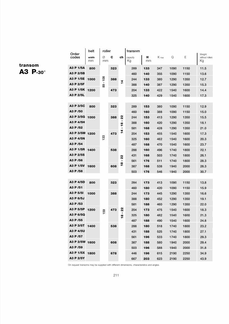
7/27/2019 31801183 Idler Roller
http://slidepdf.com/reader/full/31801183-idler-roller 213/308
211
transom
A3 P -30 °
Order codes
belt roller transomWeight
width Ø C ch capacity H K max Q E without rolle
mm mm Kg mm Kg
800 323 289 133 347 1090 1150 11.5
460 140 355 1090 1150 13.6
1000 388 244 133 380 1290 1350 12.7
388 140 387 1290 1350 15.3
1200 473 204 133 422 1540 1600 14.4
325 140 429 1540 1600 17.3
800 323 289 153 380 1090 1150 12.9
460 160 388 1090 1150 15.01000 388 244 153 413 1290 1350 15.5
388 160 420 1290 1350 18.1
581 168 428 1290 1350 21.0
1200 473 204 153 455 1540 1600 17.3
325 160 462 1540 1600 20.3
487 168 470 1540 1600 23.7
1400 538 288 160 496 1740 1800 22.1
431 168 503 1740 1800 26.1
561 176 511 1740 1800 28.3
1600 608 387 168 538 1940 2000 28.3503 176 546 1940 2000 30.7
800 323 284 173 413 1090 1150 13.8
460 180 420 1090 1150 15.9
1000 388 244 173 445 1290 1350 16.6
388 180 452 1290 1350 19.1
581 188 460 1290 1350 22.0
1200 473 204 173 475 1540 1600 18.3
325 180 482 1540 1600 21.3
487 188 490 1540 1600 24.8
1400 538 288 180 518 1740 1800 23.2
431 188 525 1740 1800 27.1
561 196 533 1740 1800 29.3
1600 608 387 188 580 1940 2000 29.4
503 196 588 1940 2000 31.8
1800 678 446 196 615 2190 2250 34.9
667 203 623 2190 2250 43.9
159
18 - 22
14
89 - 108
133
14 - 18 - 22
18 - 22
A3 P 1/5A
A3 P 2/5B
A3 P 1/5E
A3 P 2/5F
A3 P 1/5K
A3 P 2/5L
A3 P 3/5C
A3 P /50 A3 P 3/5G
A3 P 4/5H
A3 P /52
A3 P 3/5M
A3 P 4/5N
A3 P /54
A3 P 1/5R
A3 P 2/5S
A3 P /56
A3 P 1/5V A3 P /58
A3 P 4/5D
A3 P /51
A3 P 5/5I
A3 P 6/5J
A3 P /53
A3 P 5/5P
A3 P 6/5Q
A3 P /55
A3 P 3/5T
A3 P 4/5U
A3 P /57
A3 P 2/5W
A3 P /59
A3 P 1/5X
A3 P 2/5Y
On request transoms may be supplied with different dimensions, characteristics and angles.
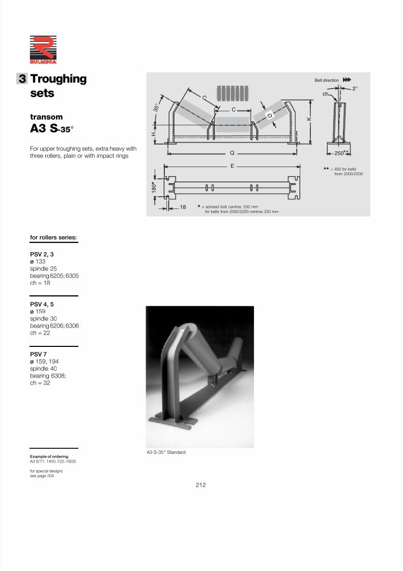
7/27/2019 31801183 Idler Roller
http://slidepdf.com/reader/full/31801183-idler-roller 214/308
212
®
3 Troughing
setstransom
A3 S -35 °
Example of ordering A3 S/77, 1400, F22, H205
for special designssee page 204
ch
250 **
C
Q
E
3 5
°
H
KØ
C
2 °
1 8 0
18
Belt direction
* = advised bolt centres 200 mmfor belts from 2000/2200 centres 330 mm
** = 450 for beltsfrom 2000/2200
PSV 2, 3ø 133spindle 25bearing 6205; 6305ch = 18
PSV 4, 5ø 159spindle 30bearing 6206; 6306ch = 22
PSV 7ø 159, 194spindle 40bearing 6308;ch = 32
for rollers series:
*
For upper troughing sets, extra heavy withthree rollers, plain or with impact rings
A3 S-35 ° Standard
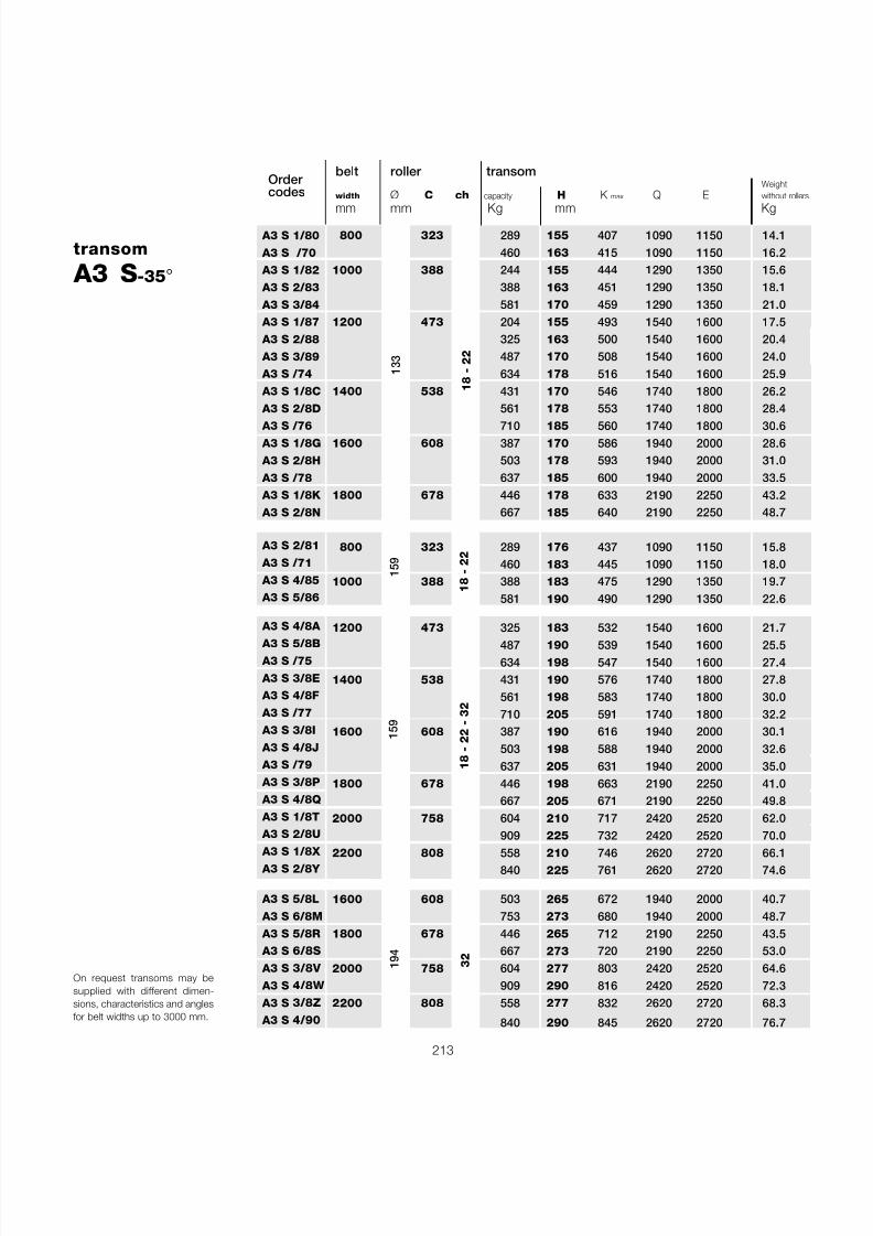
7/27/2019 31801183 Idler Roller
http://slidepdf.com/reader/full/31801183-idler-roller 215/308
213
133
194
32
18 - 22 - 32
159
18 - 22
On request transoms may besupplied with different dimen-sions, characteristics and anglesfor belt widths up to 3000 mm.
belt roller transomWeight
width Ø C ch capacity H K max Q E without rolle
mm mm Kg mm Kg800 323 289 155 407 1090 1150 14.1
460 163 415 1090 1150 16.21000 388 244 155 444 1290 1350 15.6
388 163 451 1290 1350 18.1581 170 459 1290 1350 21.0
1200 473 204 155 493 1540 1600 17.5325 163 500 1540 1600 20.4487 170 508 1540 1600 24.0634 178 516 1540 1600 25.9
1400 538 431 170 546 1740 1800 26.2561 178 553 1740 1800 28.4
710 185 560 1740 1800 30.61600 608 387 170 586 1940 2000 28.6
503 178 593 1940 2000 31.0637 185 600 1940 2000 33.5
1800 678 446 178 633 2190 2250 43.2667 185 640 2190 2250 48.7
800 323 289 176 437 1090 1150 15.8460 183 445 1090 1150 18.0
1000 388 388 183 475 1290 1350 19.7581 190 490 1290 1350 22.6
1200 473 325 183 532 1540 1600 21.7487 190 539 1540 1600 25.5634 198 547 1540 1600 27.4
1400 538 431 190 576 1740 1800 27.8561 198 583 1740 1800 30.0710 205 591 1740 1800 32.2
1600 608 387 190 616 1940 2000 30.1503 198 588 1940 2000 32.6637 205 631 1940 2000 35.0
1800 678 446 198 663 2190 2250 41.0667 205 671 2190 2250 49.8
2000 758 604 210 717 2420 2520 62.0909 225 732 2420 2520 70.0
2200 808 558 210 746 2620 2720 66.1840 225 761 2620 2720 74.6
1600 608 503 265 672 1940 2000 40.7753 273 680 1940 2000 48.7
1800 678 446 265 712 2190 2250 43.5667 273 720 2190 2250 53.0
2000 758 604 277 803 2420 2520 64.6909 290 816 2420 2520 72.3
2200 808 558 277 832 2620 2720 68.3
840 290 845 2620 2720 76.7
159
18 - 22
transom
A3 S -35 °
A3 S 1/80
A3 S /70
A3 S 1/82
A3 S 2/83
A3 S 3/84
A3 S 1/87
A3 S 2/88
A3 S 3/89
A3 S /74
A3 S 1/8C
A3 S 2/8D
A3 S /76 A3 S 1/8G
A3 S 2/8H
A3 S /78
A3 S 1/8K
A3 S 2/8N
A3 S 2/81
A3 S /71
A3 S 4/85
A3 S 5/86
A3 S 4/8A
A3 S 5/8B
A3 S /75
A3 S 3/8E
A3 S 4/8F
A3 S /77
A3 S 3/8I
A3 S 4/8J
A3 S /79
A3 S 3/8P
A3 S 4/8Q
A3 S 1/8T
A3 S 2/8U
A3 S 1/8X A3 S 2/8Y
A3 S 5/8L
A3 S 6/8M
A3 S 5/8R
A3 S 6/8S
A3 S 3/8V
A3 S 4/8W
A3 S 3/8Z
A3 S 4/90
Order codes
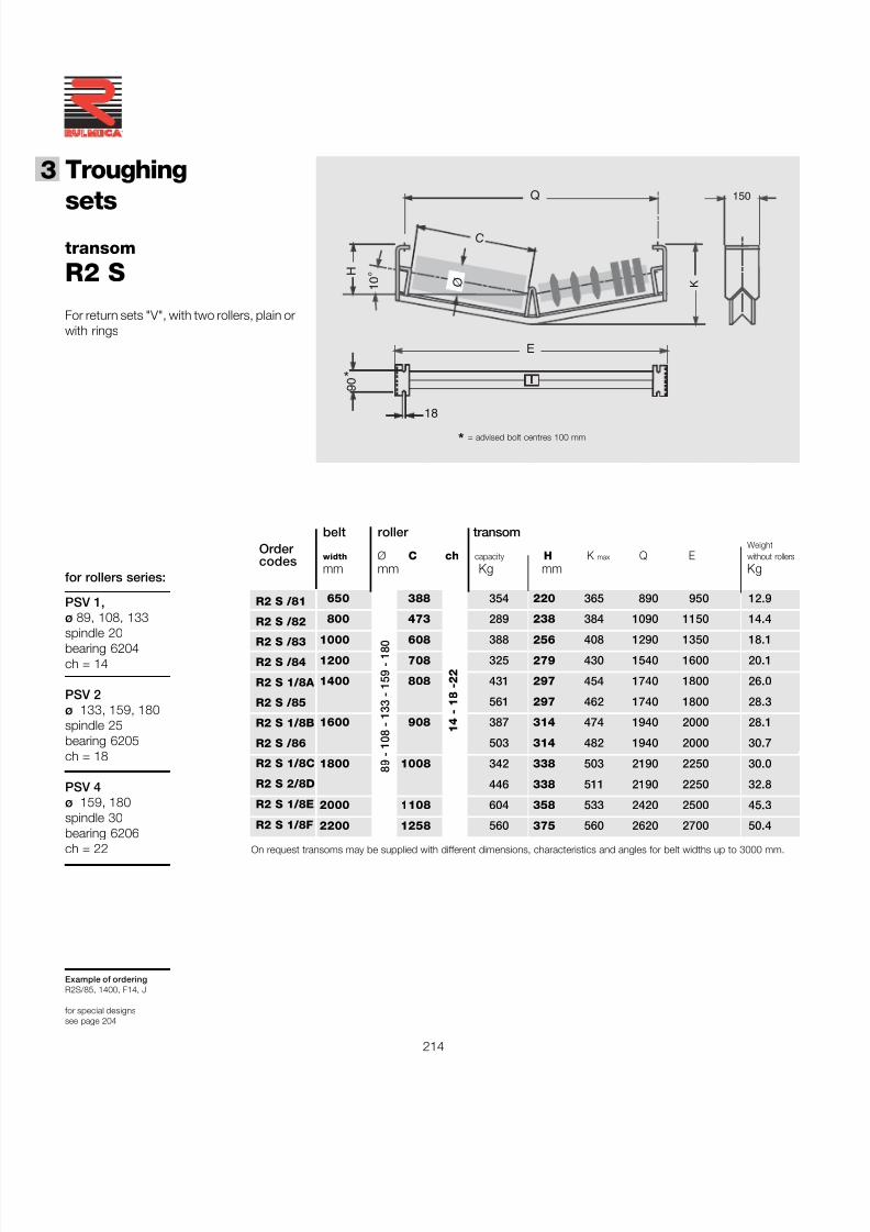
7/27/2019 31801183 Idler Roller
http://slidepdf.com/reader/full/31801183-idler-roller 216/308
214
®
3 Troughing
setstransom
R2 S
Example of orderingR2S/85, 1400, F14, J
for special designssee page 204
Q
H
C
Ø
E
150
9 0
18
1 0
°
K
*
for rollers series:
PSV 1,ø 89, 108, 133
spindle 20bearing 6204ch = 14
PSV 2ø 133, 159, 180spindle 25bearing 6205ch = 18
PSV 4ø 159, 180spindle 30bearing 6206ch = 22
For return sets "V", with two rollers, plain orwith rings
* = advised bolt centres 100 mm
14 - 18 -22
belt roller transomWeight
width Ø C ch capacity H K max Q E without rollers
mm mm Kg mm Kg
650 388 354 220 365 890 950 12.9
800 473 289 238 384 1090 1150 14.4
1000 608 388 256 408 1290 1350 18.1
1200 708 325 279 430 1540 1600 20.1
1400 808 431 297 454 1740 1800 26.0
561 297 462 1740 1800 28.3
1600 908 387 314 474 1940 2000 28.1
503 314 482 1940 2000 30.7
1800 1008 342 338 503 2190 2250 30.0
446 338 511 2190 2250 32.8
2000 1108 604 358 533 2420 2500 45.3
2200 1258 560 375 560 2620 2700 50.4
89 - 108 - 133 - 159 - 180
R2 S /81
R2 S /82
R2 S /83
R2 S /84
R2 S 1/8A
R2 S /85
R2 S 1/8B
R2 S /86
R2 S 1/8C
R2 S 2/8D
R2 S 1/8E
R2 S 1/8F
Order codes
On request transoms may be supplied with different dimensions, characteristics and angles for belt widths up to 3000 mm.
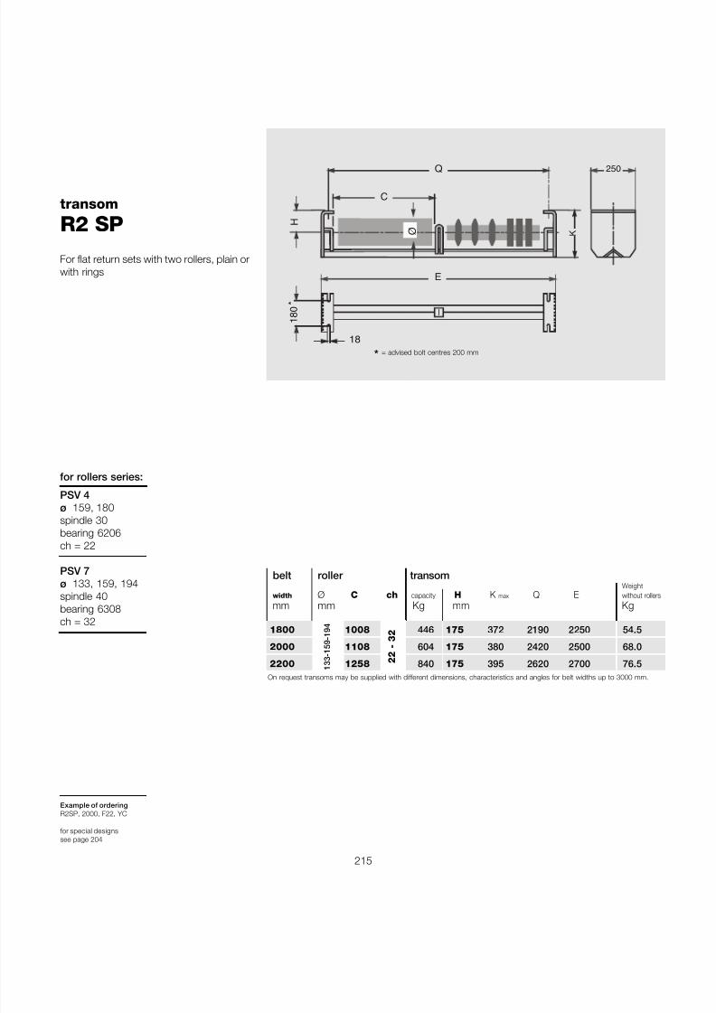
7/27/2019 31801183 Idler Roller
http://slidepdf.com/reader/full/31801183-idler-roller 217/308
215
133-159-194
belt roller transomWeight
width Ø C ch capacity H K max Q E without roller
mm mm Kg mm Kg
1800 1008 446 175 372 2190 2250 54.5
2000 1108 604 175 380 2420 2500 68.0
2200 1258 840 175 395 2620 2700 76.5On request transoms may be supplied with different dimensions, characteristics and angles for belt widths up to 3000 mm.
22 - 32
Q
H
C
Ø
E
250
1 8 0 *
18
K
* = advised bolt centres 200 mm
transom
R2 SP
Example of orderingR2SP, 2000, F22, YC
for special designssee page 204
for rollers series:
PSV 4ø 159, 180
spindle 30bearing 6206ch = 22
PSV 7ø 133, 159, 194spindle 40bearing 6308ch = 32
For flat return sets with two rollers, plain orwith rings
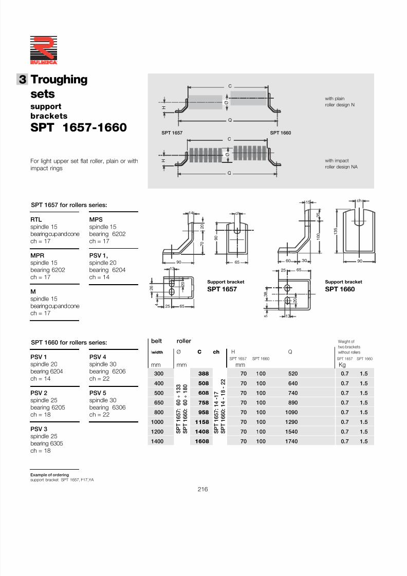
7/27/2019 31801183 Idler Roller
http://slidepdf.com/reader/full/31801183-idler-roller 218/308
216
®
3 Troughing
setssupportbrackets
SPT 1657-1660
Example of orderingsupport bracket SPT 1657, F17,YA
with plainroller design N
with impactroller design NA
Q
H Ø
C
Q
H
C
Ø
Support bracket
SPT 1657
For light upper set flat roller, plain or withimpact rings
7 0
2 0
90
14
6525
2 6
13
65
9 0
ch
2 0
4
13
6525
3 8
2 0
5
60 30
1 0 0
15
90
1 3 5
ch
3 5
Support bracket
SPT 1660
belt roller Weight of two brackets
lwidth Ø C ch H Q without rollers
SPT 1657 SPT 1660 SPT 1657 SPT 1660
mm mm mm Kg 300 388 70 100 520 0.7 1.5
400 508 70 100 640 0.7 1.5
500 608 70 100 740 0.7 1.5
650 758 70 100 890 0.7 1.5
800 958 70 100 1090 0.7 1.5
1000 1158 70 100 1290 0.7 1.5
1200 1408 70 100 1540 0.7 1.5
1400 1608 70 100 1740 0.7 1.5
SPT 1657: 60 ÷
133
SPT 1660: 60 ÷
180
SPT 1657: 14 -17
SPT 1660: 14 - 18 - 22
SPT 1657 SPT 1660
PSV 1spindle 20bearing 6204ch = 14
PSV 2spindle 25bearing 6205ch = 18
PSV 3spindle 25bearing 6305ch = 18
PSV 4spindle 30bearing 6206ch = 22
PSV 5spindle 30bearing 6306ch = 22
SPT 1660 for rollers series:
RTLspindle 15bearing cup and conech = 17
MPRspindle 15bearing 6202ch = 17
Mspindle 15bearing cup and conech = 17
MPSspindle 15bearing 6202ch = 17
PSV 1,spindle 20bearing 6204ch = 14
SPT 1657 for rollers series:
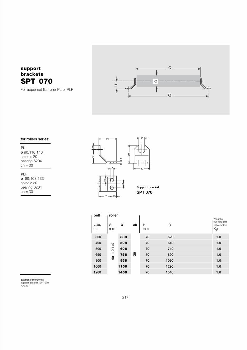
7/27/2019 31801183 Idler Roller
http://slidepdf.com/reader/full/31801183-idler-roller 219/308
217
supportbrackets
SPT 070
Example of orderingsupport bracket SPT 070,F30,YC
7 0
2 0
90
6
65 25
4 0
80
ch
9 0
15
2 0
Q
H Ø
C
belt roller Weight of two brackets
width Ø C ch H Q without rollers
mm mm mm Kg
300 388 70 520 1.0
400 508 70 640 1.0
500 608 70 740 1.0
650 758 70 890 1.0
800 958 70 1090 1.0
1000 1158 70 1290 1.0
1200 1408 70 1540 1.0
30
90-110-140
for rollers series:
PLø 90,110,140spindle 20bearing 6204ch = 30
PLFø 89,108,133spindle 20bearing 6204ch = 30
Support bracket
SPT 070
For upper set flat roller PL or PLF
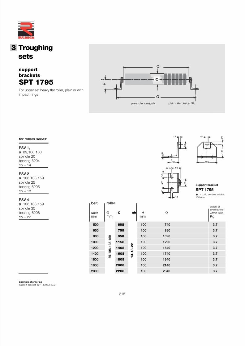
7/27/2019 31801183 Idler Roller
http://slidepdf.com/reader/full/31801183-idler-roller 220/308
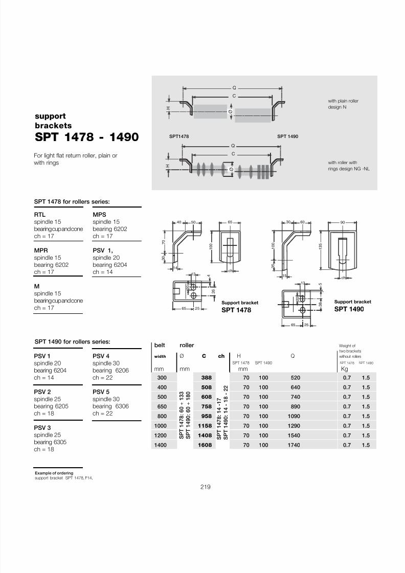
7/27/2019 31801183 Idler Roller
http://slidepdf.com/reader/full/31801183-idler-roller 221/308
219
supportbrackets
SPT 1478 - 1490
Example of orderingsupport bracket SPT 1478, F14,
with plain rollerdesign N
with roller withrings design NG -NL
H
C
Ø
Q
H
C
Ø
Q
For light flat return roller, plain orwith rings
65
1 0 0
13ch
5040
7 0
3 0
14
65 25
2 6
2 0
4
belt roller Weight of two brackets
width Ø C ch H Q without rollers
SPT 1478 SPT 1490 SPT 1478 SPT 1490
mm mm mm Kg 300 388 70 100 520 0.7 1.5
400 508 70 100 640 0.7 1.5
500 608 70 100 740 0.7 1.5
650 758 70 100 890 0.7 1.5
800 958 70 100 1090 0.7 1.5
1000 1158 70 100 1290 0.7 1.5
1200 1408 70 100 1540 0.7 1.5
1400 1608 70 100 1740 0.7 1.5
SPT 1478: 60 ÷ 133
SPT 1490: 60 ÷ 180
Support bracket
SPT 1478Support bracket
SPT 1490
SPT 1478: 14 -17
SPT 1490: 14 - 18 - 22
90
1 3 5
13
ch
6030
1 0 0
3 5
15
65 25
3 8
2 0
5
SPT1478 SPT 1490
SPT 1478 for rollers series:
RTLspindle 15bearing cup and conech = 17
MPRspindle 15bearing 6202ch = 17
M
spindle 15bearing cup and conech = 17
MPSspindle 15bearing 6202ch = 17
PSV 1,spindle 20bearing 6204ch = 14
PSV 1spindle 20bearing 6204ch = 14
PSV 2spindle 25bearing 6205ch = 18
PSV 3spindle 25bearing 6305ch = 18
PSV 4spindle 30bearing 6206ch = 22
PSV 5spindle 30bearing 6306ch = 22
SPT 1490 for rollers series:
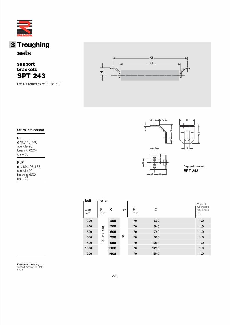
7/27/2019 31801183 Idler Roller
http://slidepdf.com/reader/full/31801183-idler-roller 222/308
220
®
3 Troughing
setssupportbrackets
SPT 243
Example of orderingsupport bracket SPT 243,F30,Z
50 40
7 0
3 0
6
25 65
4 0
15
2 0
80
1 0 0
ch
H
C
Q
for rollers series:
PLø 90,110,140spindle 20bearing 6204ch = 30
PLF
ø , 89,108,133spindle 20bearing 6204ch = 30
belt roller Weight of two brackets
width Ø C ch H Q without rollers
mm mm mm Kg
300 388 70 520 1.0
400 508 70 640 1.0
500 608 70 740 1.0
650 758 70 890 1.0
800 958 70 1090 1.0
1000 1158 70 1290 1.0
1200 1408 70 1540 1.0
30
90-110-140
Support bracket
SPT 243
For flat return roller PL or PLF
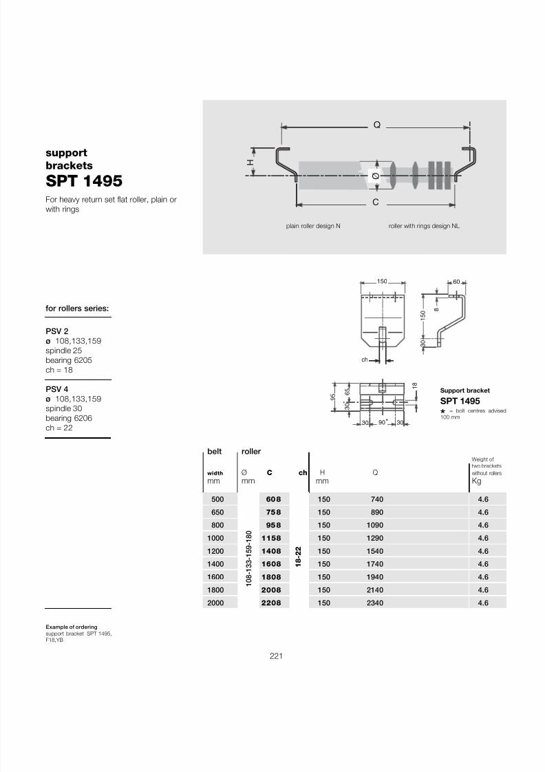
7/27/2019 31801183 Idler Roller
http://slidepdf.com/reader/full/31801183-idler-roller 223/308
221
supportbrackets
SPT 1495
Example of orderingsupport bracket SPT 1495,F18,YB
Q
H
C
Ø
plain roller design N roller with rings design NL
Support bracket
SPT 1495
belt roller Weight of two brackets
width Ø C ch H Q without rollers
mm mm mm Kg
500 608 150 740 4.6
650 758 150 890 4.6
800 958 150 1090 4.6
1000 1158 150 1290 4.6
1200 1408 150 1540 4.6
1400 1608 150 1740 4.6
1600 1808 150 1940 4.6
1800 2008 150 2140 4.6
2000 2208 150 2340 4.6
18-22
108-133-159-180
for rollers series:
PSV 2ø 108,133,159spindle 25bearing 6205ch = 18
PSV 4ø 108,133,159spindle 30bearing 6206ch = 22
150
3 0
6 5
30 90 30
1 8
ch
*
60
1 5 0
3 0
8
9 5
For heavy return set flat roller, plain orwith rings
* = bolt centres advised100 mm
7/27/2019 31801183 Idler Roller
http://slidepdf.com/reader/full/31801183-idler-roller 224/308
222
®
3 Troughing
sets
The installation of the self-centralisingtroughing sets is advised to be positionedon the upper strand rather than the returnsection, and used only when the workingconditions require.
Self - centralising troughing set for loaded strand of belt
The self-centralising troughing sets aredesigned and manufactured in a way thatallows them to be entirely interchangeablewith the normal transom.
Normally it is a good standard to installthem at an approximate distance of 15metre from the pulley and at a pitch of about 30 m.
It is not advised to use self-centralisingtroughing sets on very short conveyors.
The self-centralising troughing sets aredesigned in 3 different versions : model
S, with rigid arm; model F, with pivotingarm with brake; model R, with centrali-sed pivoting arm with brake, for rever-sible belts.
3.4 - Self-centralising troughing sets
Sometimes the difficult working conditionsof the plant results in a lateral movement of the belt. In this case a self-centralisingtroughing set is used which acts in a waythat corrects the belt tracking and main-tains it constantly in the central position.
The self-centralising troughing set is design-ed as a series of rollers arranged in a troughpositioned onto the supporting transomwhich itself is fixed to a slewing ring Fig. 5which permits rotation.
The slewing ring (a large ball bearing) per-mits a rotation limited to 5-8 degrees andis sized in proportion to the vertical loading;a tapered roller bearing assembled to theshaft of the slewing ring, absorbs any sideforces or overturning pressures.
Fig. 5
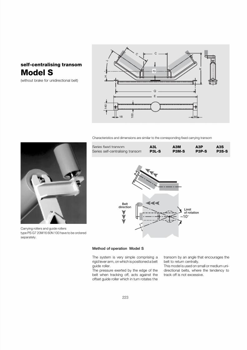
7/27/2019 31801183 Idler Roller
http://slidepdf.com/reader/full/31801183-idler-roller 225/308
223
Method of operation Model S
The system is very simple comprising arigid lever arm, on which is positioned a beltguide roller.
The pressure exerted by the edge of thebelt when tracking off, acts against theoffset guide roller which in turn rotates the
~10 °
Limitof rotation
Beltdirection
self-centralising transom
Model S(without brake for unidirectional belt)
Ø
C
Q
E
H
1 4 0
C
λ
80 1 0 0
18
K
Characteristics and dimensions are similar to the corresponding fixed carrying transom
Series fixed transom A3L A3M A3P A3SSeries self-centralising transom P3L-S P3M-S P3P-S P3S-S
Carrying rollers and guide rollerstype PS G7 20M16 60N 100 have to be orderedseparately.
transom by an angle that encourages thebelt to return centrally.
This model is used on small or medium uni-directional belts, where the tendency totrack off is not excessive.
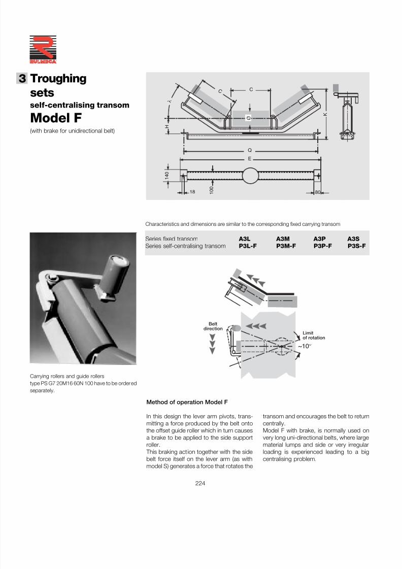
7/27/2019 31801183 Idler Roller
http://slidepdf.com/reader/full/31801183-idler-roller 226/308
224
®
3 Troughing
sets
Method of operation Model F
In this design the lever arm pivots, trans-mitting a force produced by the belt ontothe offset guide roller which in turn causesa brake to be applied to the side supportroller.
This braking action together with the sidebelt force itself on the lever arm (as withmodel S) generates a force that rotates the
~10 °
Limitof rotation
Beltdirection
1 4 0
80 1 0 0
18
Ø
C
Q
E
H
C
λ
K
self-centralising transom
Model F(with brake for unidirectional belt)
Characteristics and dimensions are similar to the corresponding fixed carrying transom
Series fixed transom A3L A3M A3P A3SSeries self-centralising transom P3L-F P3M-F P3P-F P3S-F
Carrying rollers and guide rollerstype PS G7 20M16 60N 100 have to be ordered
separately.
transom and encourages the belt to returncentrally.Model F with brake, is normally used onvery long uni-directional belts, where largematerial lumps and side or very irregularloading is experienced leading to a bigcentralising problem.
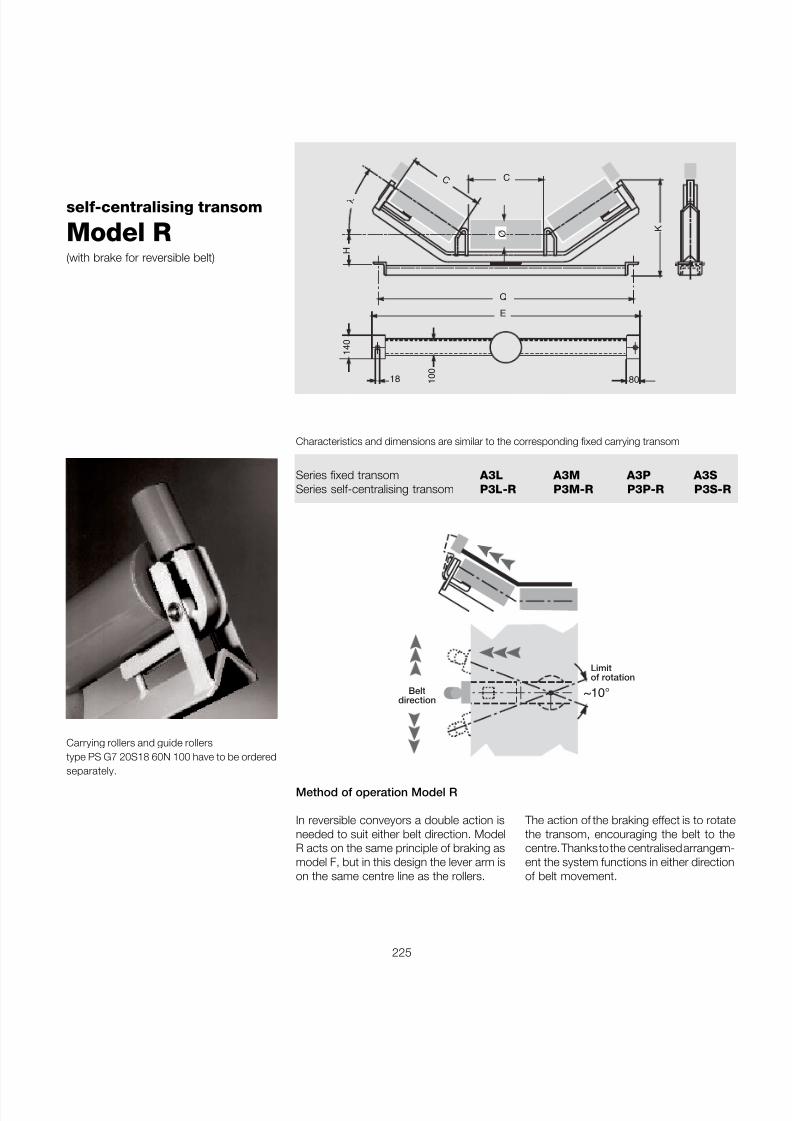
7/27/2019 31801183 Idler Roller
http://slidepdf.com/reader/full/31801183-idler-roller 227/308
225
Method of operation Model R
In reversible conveyors a double action isneeded to suit either belt direction. ModelR acts on the same principle of braking asmodel F, but in this design the lever arm ison the same centre line as the rollers.
~10 °
Limitof rotation
Beltdirection
1 4 0
80 1 0 0
18
Ø
C
Q
E
H
C
λ
K
self-centralising transom
Model R(with brake for reversible belt)
Characteristics and dimensions are similar to the corresponding fixed carrying transom
Series fixed transom A3L A3M A3P A3SSeries self-centralising transom P3L-R P3M-R P3P-R P3S-R
The action of the braking effect is to rotatethe transom, encouraging the belt to thecentre. Thanks to the centralised arrangem-ent the system functions in either directionof belt movement.
Carrying rollers and guide rollerstype PS G7 20S18 60N 100 have to be ordered
separately.
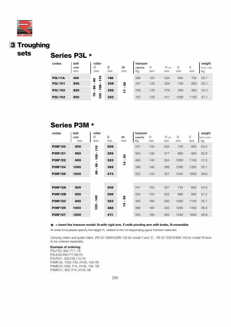
7/27/2019 31801183 Idler Roller
http://slidepdf.com/reader/full/31801183-idler-roller 228/308
226
®
3 Troughing
sets
codes belt roller transom weightwidth Ø C ch capacity H K max Q E without rollers
mm mm mm mm Kg mm mm mm mm kg
P3M*/20 500 208 247 135 292 740 800 23.5
P3M*/21 650 258 354 135 317 890 950 25.9
P3M*/22 800 323 460 140 354 1090 1150 31.5
P3M*/24 1000 388388 140 386 1290 1350 35.1
P3M*/26 1200 473 325 140 427 1540 1600 39.6
P3M*/2A 500 208 247 155 327 740 800 24.8
P3M*/2B 650 258 354 155 352 890 950 27.2
P3M*/23 800 323 460 160 390 1090 1150 32.7
P3M*/25 1000 388 388 160 422 1290 1350 36.3
P3M*/27 1200 47 3 325 160 465 1540 1600 40.8
89 - 90 - 108 -110
14 - 30
Series P3M *
* = insert the transom model: S=with rigid arm, F=with pivoting arm with brake, R=reversible At order time please specify the height H, related to the corresponding upper transom selec ted.
Carrying rollers and guide rollers (PS G7 20M16 60N 100 for model F and S , PS G7 20S18 60N 100 for model R) haveto be ordered separately.
codes belt roller transom weightwidth Ø C ch capacity H K max Q E without rollers
mm mm mm mm Kg mm mm mm mm kg
P3L*/1A 400 168 286 125 334 640 700 20.7
P3L*/01 500 208 247 125 354 740 800 22.1
P3L*/02 650 258 205 125 379 890 950 24.3
P3L*/03 800 323 167 125 411 1090 1150 27.1
17 - 30
76 - 89 - 90
102 -108 -110
Series P3L *
Example of ordering:P3LF/03, 800, F17, 76P3LS/02,650,F17,89,YA P3LR/01, 500,F30,110,YA P3MF/25, 1000, F30, H160, 140 YBP3MS/24,1000, F14, H140, 108, YBP3MR/21, 650, F14, H135, 89
133 -140
14 - 30
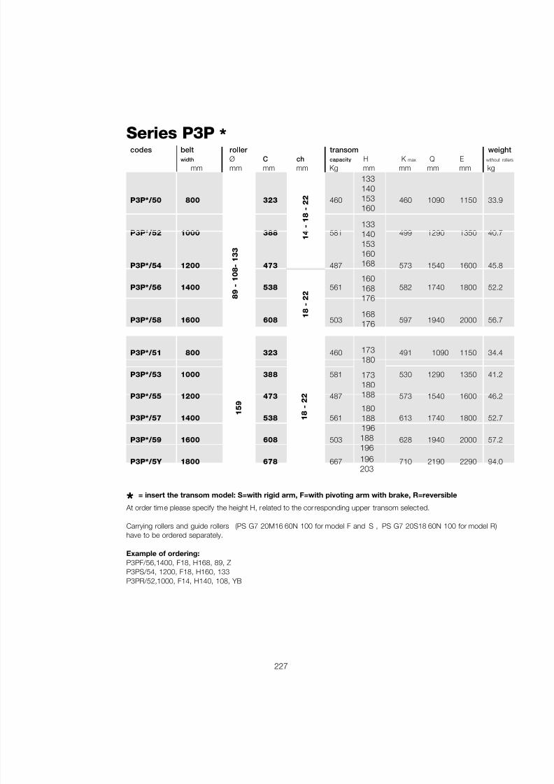
7/27/2019 31801183 Idler Roller
http://slidepdf.com/reader/full/31801183-idler-roller 229/308
227
Series P3P *
18 - 22
159
* = insert the transom model: S=with rigid arm, F=with pivoting arm with brake, R=reversible
At order time please specify the height H, related to the corresponding upper transom selected.
Carrying rollers and guide rollers (PS G7 20M16 60N 100 for model F and S , PS G7 20S18 60N 100 for model R)have to be ordered separately.
Example of ordering:P3PF/56,1400, F18, H168, 89, ZP3PS/54, 1200, F18, H160, 133P3PR/52,1000, F14, H140, 108, YB
14 - 18 - 22
89 - 108- 133
codes belt roller transom weightwidth Ø C ch capacity H K max Q E without rolle
mm mm mm mm Kg mm mm mm mm kg
P3P*/50 800 323 460 460 1090 1150 33.9
P3P*/52 1000 388 581 499 1290 1350 40.7
P3P*/54 1200 473487 573 1540 1600 45.8
P3P*/56 1400 538 561 582 1740 1800 52.2
P3P*/58 1600 608 503 597 1940 2000 56.7
P3P*/51 800 323 460 491 1090 1150 34.4
P3P*/53 1000 388 581 530 1290 1350 41.2
P3P*/55 1200 473 487 573 1540 1600 46.2
P3P*/57 1400 538 561 613 1740 1800 52.7
P3P*/59 1600 608 503 628 1940 2000 57.2
P3P*/5Y 1800 678 667 710 2190 2290 94.0
133140153160
133140153160168
173180188
18 - 22
168176
173180
180188196188196196203
160168176
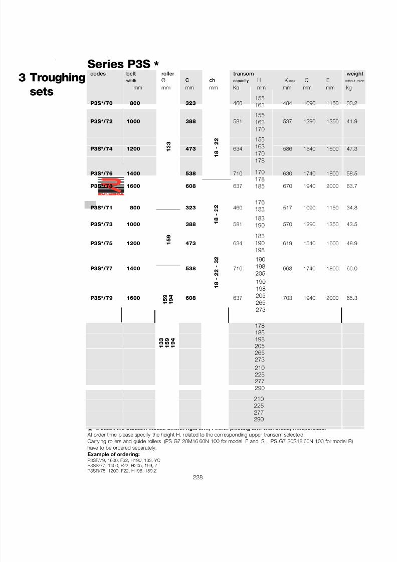
7/27/2019 31801183 Idler Roller
http://slidepdf.com/reader/full/31801183-idler-roller 230/308
228
®
3 Troughing
sets
codes belt roller transom weightwitdh Ø C ch capacity H K max Q E without rollers
mm mm mm mm Kg mm mm mm mm kg
P3S*/70 800 323 460 484 1090 1150 33.2
P3S*/72 1000 388 581 537 1290 1350 41.9
P3S*/74 1200 473 634 586 1540 1600 47.3
P3S*/76 1400 538 710 630 1740 1800 58.5
P3S*/78 1600 608 637 670 1940 2000 63.7
P3S*/71 800 323 460 517 1090 1150 34.8
P3S*/73 1000 388 581 570 1290 1350 43.5
P3S*/75 1200 473 634 619 1540 1600 48.9
P3S*/77 1400 538 710 663 1740 1800 60.0
P3S*/79 1600 608 637 703 1940 2000 65.3
P3S*/8S 1800 678 667 849 2190 2290 104.0
P3S*/8W 2000 758 909 912 2420 2520 126.6
P3S*/90 2200 808 840 641 2620 2720 133.1
133
Series P3S *
18 - 22
159
159 - 19
4
18 - 22 - 32
* = insert the transom model: S=with rigid arm, F=with pivoting arm with brake, R=reversible. At order time please specify the height H, related to the corresponding upper transom selected.Carrying rollers and guide rollers (PS G7 20M16 60N 100 for model F and S , PS G7 20S18 60N 100 for model R)have to be ordered separately.Example of ordering:P3SF/79, 1600, F32, H190, 133, YCP3SS/77, 1400, F22, H205, 159, ZP3SR/75, 1200, F22, H198, 159,Z
155163
155163170
155163170178
170178185
18 - 22
176183
183190
183190198
190198205
18 - 22 - 32
190
198205265273
178185198205265273
159
194
210225277290
210225277290
133
159
194
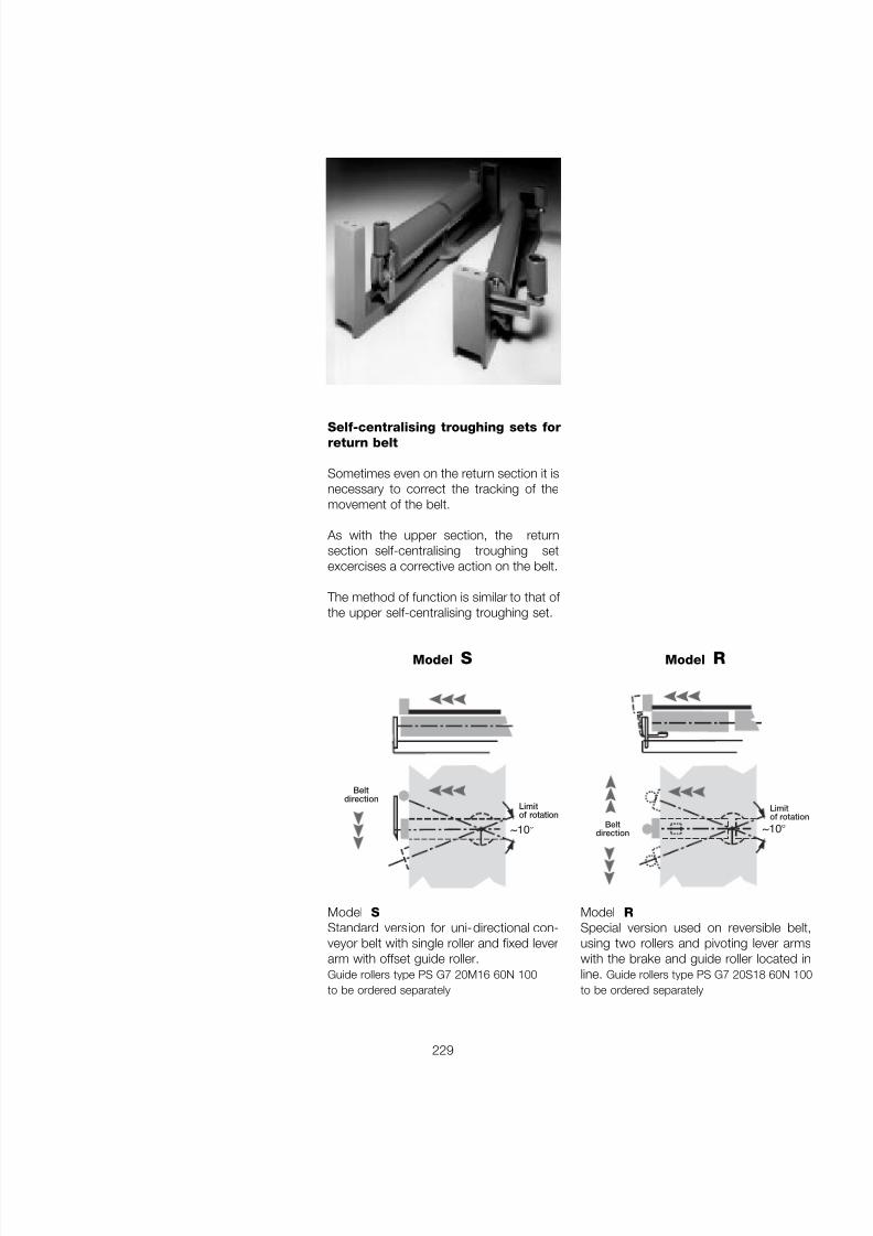
7/27/2019 31801183 Idler Roller
http://slidepdf.com/reader/full/31801183-idler-roller 231/308
229
Self-centralising troughing sets forreturn belt
Sometimes even on the return section it isnecessary to correct the tracking of themovement of the belt.
As with the upper section, the returnsection self-centralising troughing setexcercises a corrective action on the belt.
The method of function is similar to that of the upper self-centralising troughing set.
Model SStandard version for uni-directional con-veyor belt with single roller and fixed leverarm with offset guide roller.Guide rollers type PS G7 20M16 60N 100to be ordered separately
Model RSpecial version used on reversible belt,using two rollers and pivoting lever armswith the brake and guide roller located inline. Guide rollers type PS G7 20S18 60N 100to be ordered separately
~10 °
Limitof rotation
Beltdirection
~10 °
Limitof rotation
Beltdirection
Model S Model R
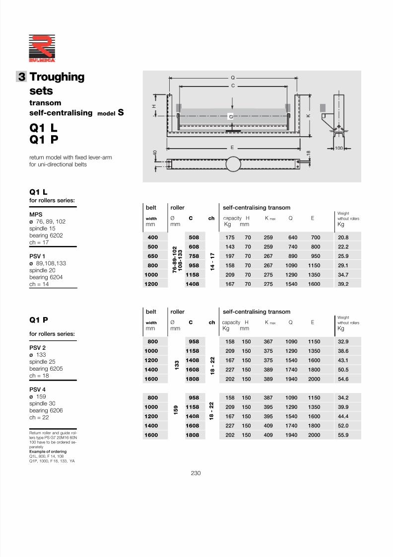
7/27/2019 31801183 Idler Roller
http://slidepdf.com/reader/full/31801183-idler-roller 232/308
230
®
3 Troughing
sets
Return roller and guide rol-lers type PS G7 20M16 60N100 have to be ordered se-paratelyExample of orderingQ1L, 800, F 14, 108Q1P, 1000, F 18, 133, YA
Q1 L
Q1 P
for rollers series:
MPSø 76, 89, 102spindle 15bearing 6202ch = 17
PSV 1ø 89,108,133spindle 20bearing 6204ch = 14
for rollers series:
PSV 2ø 133spindle 25bearing 6205ch = 18
PSV 4ø 159spindle 30bearing 6206ch = 22
belt roller self-centralising transomWeight
width Ø C ch capacity H K max Q E without rollers
mm mm Kg mm Kg
800 958 158 150 367 1090 1150 32.9
1000 1158 209 150 375 1290 1350 38.6
1200 1408 167 150 375 1540 1600 43.1
1400 1608 227 150 389 1740 1800 50.5
1600 1808 202 150 389 1940 2000 54.6
800 958 158 150 387 1090 1150 34.2
1000 1158 209 150 395 1290 1350 39.9
1200 1408 167 150 395 1540 1600 44.4
1400 1608 227 150 409 1740 1800 52.0
1600 1808 202 150 409 1940 2000 55.9
belt roller self-centralising transomWeight
width Ø C ch capacity H K max Q E without rollers
mm mm Kg mm Kg
400 508 175 70 259 640 700 20.8
500 608 143 70 259 740 800 22.2
650 758 197 70 267 890 950 25.9
800 958 158 70 267 1090 1150 29.1
1000 1158 209 70 275 1290 1350 34.7
1200 1408 167 70 275 1540 1600 39.2
14 - 17
133
18 - 22
159
18 - 22
H
K
Q
E
Ø
100 4 0
C
1 8
76-89-102
108-133
transomself-centralising model S
Q1 LQ1 Preturn model with fixed lever-armfor uni-directional belts
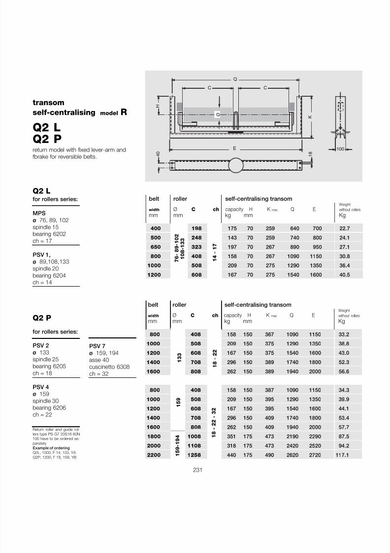
7/27/2019 31801183 Idler Roller
http://slidepdf.com/reader/full/31801183-idler-roller 233/308
231
Return roller and guide rol-lers type PS G7 20S18 60N100 have to be ordered se-paratelyExample of orderingQ2L, 1000, F 14, 133, YA Q2P, 1200, F 18, 159, YB
Q2 L
Q2 P
for rollers series:
MPSø 76, 89, 102spindle 15bearing 6202ch = 17
PSV 1,ø 89,108,133spindle 20bearing 6204
ch = 14
for rollers series:
PSV 2ø 133spindle 25bearing 6205ch = 18
PSV 4ø 159spindle 30bearing 6206ch = 22
H
K
Q
E
Ø
100
C C
4 0
1 8
transomself-centralising model R
Q2 LQ2 Preturn model with fixed lever-arm andfbrake for reversible belts.
belt roller self-centralising transomWeight
width Ø C ch capacity H K max Q E without roller
mm mm kg mm Kg
400 198 175 70 259 640 700 22.7
500 248 143 70 259 740 800 24.1
650 323 197 70 267 890 950 27.1
800 408 158 70 267 1090 1150 30.8
1000 508 209 70 275 1290 1350 36.4
1200 608 167 70 275 1540 1600 40.5
belt roller self-centralising transomWeight
width Ø C ch capacity H K max Q E without roller
mm mm kg mm Kg
800 408 158 150 367 1090 1150 33.2
1000 508 209 150 375 1290 1350 38.8
1200 608 167 150 375 1540 1600 43.0
1400 708 296 150 389 1740 1800 52.3
1600 808 262 150 389 1940 2000 56.6
800 408 158 150 387 1090 1150 34.3
1000 508 209 150 395 1290 1350 39.9
1200 608 167 150 395 1540 1600 44.1
1400 708 296 150 409 1740 1800 53.4
1600 808 262 150 409 1940 2000 57.7
1800 1008 351 175 473 2190 2290 87.5
2000 1108 318 175 473 2420 2520 94.2
2200 1258 440 175 490 2620 2720 117.1
133
18 - 22
159
18 - 22 - 32
14 - 17
76- 89-102
108-133
PSV 7ø 159, 194asse 40cuscinetto 6308ch = 32
159-194
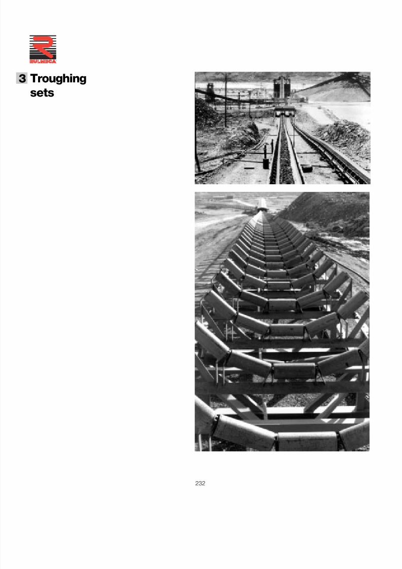
7/27/2019 31801183 Idler Roller
http://slidepdf.com/reader/full/31801183-idler-roller 234/308
232
®
3 Troughing
sets
7/27/2019 31801183 Idler Roller
http://slidepdf.com/reader/full/31801183-idler-roller 235/308
233
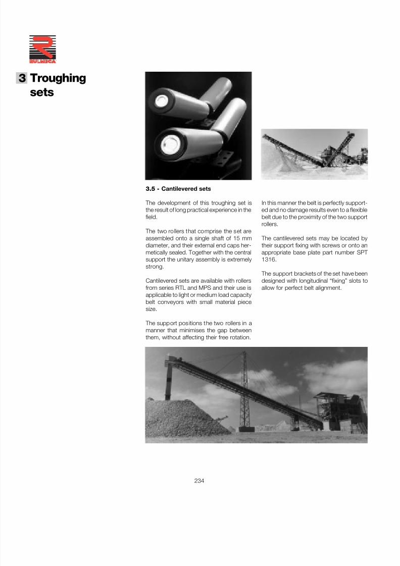
7/27/2019 31801183 Idler Roller
http://slidepdf.com/reader/full/31801183-idler-roller 236/308
234
®
3 Troughing
sets
In this manner the belt is perfectly support-ed and no damage results even to a flexiblebelt due to the proximity of the two supportrollers.
The cantilevered sets may be located bytheir support fixing with screws or onto anappropriate base plate part number SPT 1316.
The support brackets of the set have beendesigned with longitudinal “fixing” slots toallow for perfect belt alignment.
3.5 - Cantilevered sets
The development of this troughing set isthe result of long practical experience in thefield.
The two rollers that comprise the set areassembled onto a single shaft of 15 mmdiameter, and their external end caps her-metically sealed. Together with the centralsupport the unitary assembly is extremelystrong.
Cantilevered sets are available with rollersfrom series RTL and MPS and their use isapplicable to light or medium load capacitybelt conveyors with small material piecesize.
The support positions the two rollers in amanner that minimises the gap betweenthem, without affecting their free rotation.
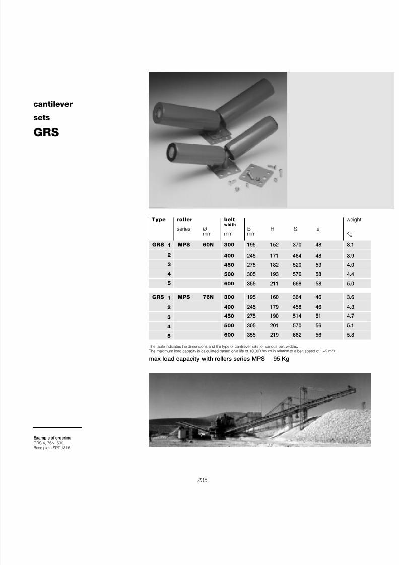
7/27/2019 31801183 Idler Roller
http://slidepdf.com/reader/full/31801183-idler-roller 237/308
235
max load capacity with rollers series MPS 95 Kg
cantilever
sets
GRS
Type roller belt weightwidth
series Ø B H S emm mm mm Kg
GRS MPS 60N 300 195 152 370 48 3.1
400 245 171 464 48 3.9
450 275 182 520 53 4.0
500 305 193 576 58 4.4
600 355 211 668 58 5.0
GRS MPS 76N 300 195 160 364 46 3.6
400 245 179 458 46 4.3
450 275 190 514 51 4.7
500 305 201 570 56 5.1
600 355 219 662 56 5.8
The table indicates the dimensions and the type of cantilever sets for various belt widths. The maximum load capacity is calculated based on a life of 10,000 hours in relation to a belt speed of 1 ÷ 2 m/s.
1
2
3
4
5
1
2
3
4
5
Example of orderingGRS 4, 76N, 500Base plate SPT 1316
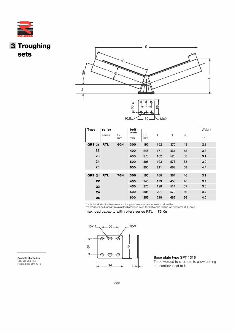
7/27/2019 31801183 Idler Roller
http://slidepdf.com/reader/full/31801183-idler-roller 238/308
236
®
3 Troughing
sets
Type roller belt Weightwidth
series Ø B H S emm mm mm Kg
GRS RTL 60N 300 195 152 370 48 2.8
400 245 171 464 48 3.8
450 275 182 520 53 3.1
500 305 193 576 58 3.2
600 355 211 668 58 4.4
GRS RTL 76N 300 195 160 364 46 3.1
400 245 179 458 46 3.4
450 275 190 514 51 3.5
500 305 201 570 56 3.7
600 355 219 662 56 4.0
The table indicates the dimensions and the type of cantilever sets for various belt widths. The maximum load capacity is calculated based on a life of 10,000 hours in relation to a belt speed of 1 ÷ 2 m/s.
Base plate type SPT 1316 To be welded to structure to allow boltingthe cantilever set to it.
21
22
23
24
25
21
22
23
24
25
Example of orderingGRS 23, 76J, 450Piastra base SPT 1316
max load capacity with rollers series RTL 75 Kg
15x11 60
94
8 5
4
6 0
12x9
S
H
4 7
2 0 °
B
Ø
e
10,5 80
8 5
12x9
6 0 60
7/27/2019 31801183 Idler Roller
http://slidepdf.com/reader/full/31801183-idler-roller 239/308
237

7/27/2019 31801183 Idler Roller
http://slidepdf.com/reader/full/31801183-idler-roller 240/308
3 Troughing
sets
238
®
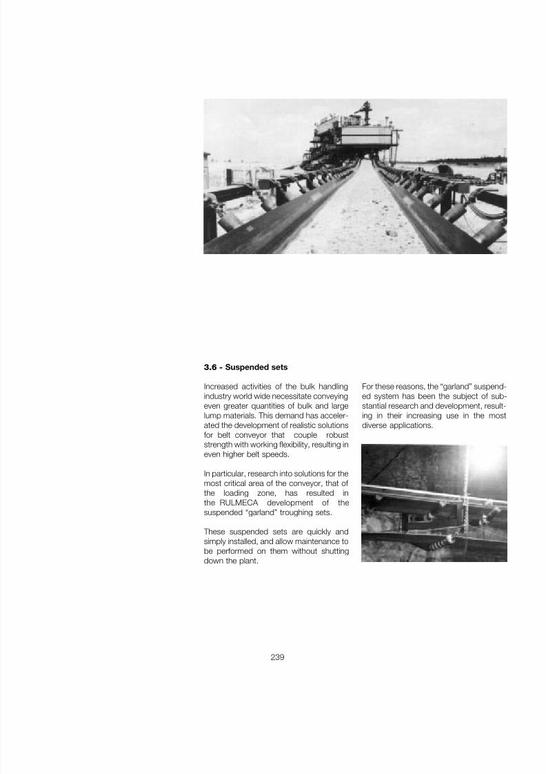
7/27/2019 31801183 Idler Roller
http://slidepdf.com/reader/full/31801183-idler-roller 241/308
239
3.6 - Suspended sets
Increased activities of the bulk handling
industry world wide necessitate conveyingeven greater quantities of bulk and largelump materials. This demand has acceler-ated the development of realistic solutionsfor belt conveyor that couple robuststrength with working flexibility, resulting ineven higher belt speeds.
In particular, research into solutions for themost critical area of the conveyor, that of the loading zone, has resulted inthe RULMECA development of thesuspended “garland” troughing sets.
These suspended sets are quickly andsimply installed, and allow maintenance tobe performed on them without shuttingdown the plant.
For these reasons, the “garland” suspend-
ed system has been the subject of sub-stantial research and development, result-ing in their increasing use in the mostdiverse applications.
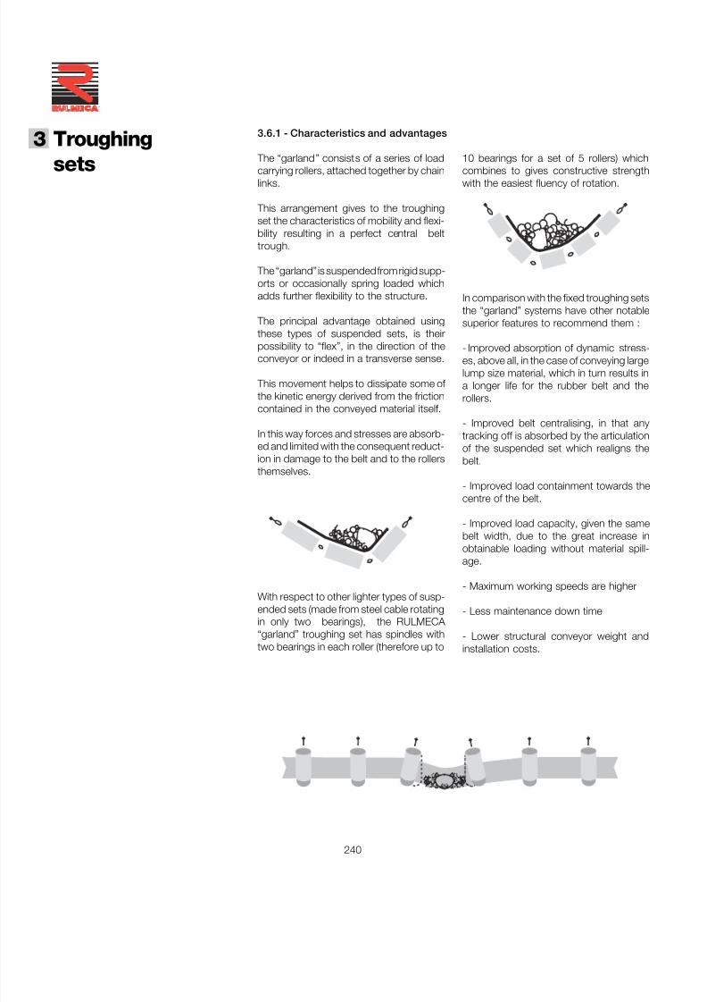
7/27/2019 31801183 Idler Roller
http://slidepdf.com/reader/full/31801183-idler-roller 242/308
3 Troughing
sets
240
®
3.6.1 - Characteristics and advantages
The “garland” consists of a series of load
carrying rollers, attached together by chainlinks.
This arrangement gives to the troughingset the characteristics of mobility and flexi-bility resulting in a perfect central belttrough.
The “garland” is suspended from rigid supp-orts or occasionally spring loaded whichadds further flexibility to the structure.
The principal advantage obtained usingthese types of suspended sets, is theirpossibility to “flex”, in the direction of theconveyor or indeed in a transverse sense.
This movement helps to dissipate some of the kinetic energy derived from the frictioncontained in the conveyed material itself.
In this way forces and stresses are absorb-ed and limited with the consequent reduct-ion in damage to the belt and to the rollersthemselves.
With respect to other lighter types of susp-ended sets (made from steel cable rotatingin only two bearings), the RULMECA “garland” troughing set has spindles withtwo bearings in each roller (therefore up to
In comparison with the fixed troughing setsthe “garland” systems have other notablesuperior features to recommend them :
- Improved absorption of dynamic stress-es, above all, in the case of conveying largelump size material, which in turn results ina longer life for the rubber belt and therollers.
- Improved belt centralising, in that anytracking off is absorbed by the articulationof the suspended set which realigns thebelt.
- Improved load containment towards thecentre of the belt.
- Improved load capacity, given the samebelt width, due to the great increase inobtainable loading without material spill-age.
- Maximum working speeds are higher
- Less maintenance down time
- Lower structural conveyor weight andinstallation costs.
10 bearings for a set of 5 rollers) which
combines to gives constructive strengthwith the easiest fluency of rotation.
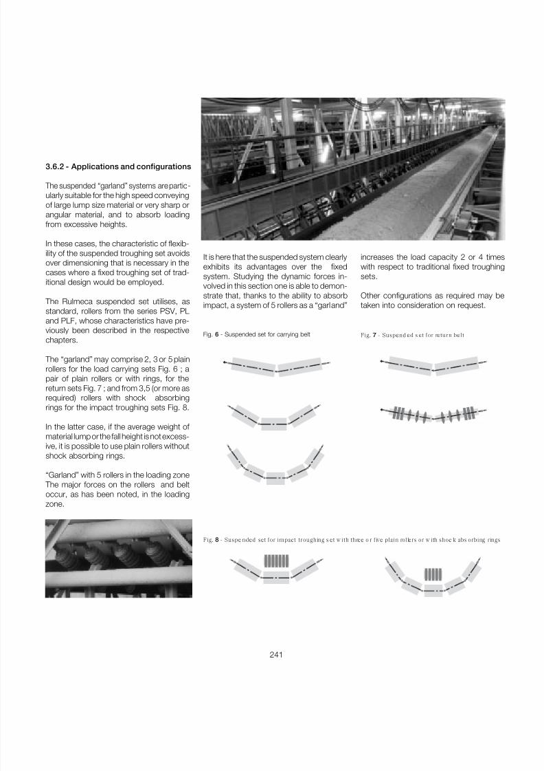
7/27/2019 31801183 Idler Roller
http://slidepdf.com/reader/full/31801183-idler-roller 243/308
241
3.6.2 - Applications and configurations
The suspended “garland” systems are partic -ularly suitable for the high speed conveyingof large lump size material or very sharp orangular material, and to absorb loadingfrom excessive heights.
In these cases, the characteristic of flexib-ility of the suspended troughing set avoids
over dimensioning that is necessary in thecases where a fixed troughing set of trad-itional design would be employed.
The Rulmeca suspended set utilises, asstandard, rollers from the series PSV, PLand PLF, whose characteristics have pre-viously been described in the respectivechapters.
The “garland” may comprise 2, 3 or 5 plainrollers for the load carrying sets Fig. 6 ; apair of plain rollers or with rings, for thereturn sets Fig. 7 ; and from 3,5 (or more as
required) rollers with shock absorbingrings for the impact troughing sets Fig. 8.
In the latter case, if the average weight of material lump or the fall height is not excess-ive, it is possible to use plain rollers withoutshock absorbing rings.
“Garland” with 5 rollers in the loading zone The major forces on the rollers and beltoccur, as has been noted, in the loadingzone.
Fig. 7 - Suspend ed s et for return beltFig. 6 - Suspended set for carrying belt
Fig. 8 - Suspe nded set for impact troughing s et w ith three o r five plain rollers or w ith shoc k abs orbing rings
It is here that the suspended system clearlyexhibits its advantages over the fixedsystem. Studying the dynamic forces in-volved in this section one is able to demon-strate that, thanks to the ability to absorbimpact, a system of 5 rollers as a “garland”
increases the load capacity 2 or 4 timeswith respect to traditional fixed troughingsets.
Other configurations as required may betaken into consideration on request.
7/27/2019 31801183 Idler Roller
http://slidepdf.com/reader/full/31801183-idler-roller 244/308
3 Troughing
sets
242
®
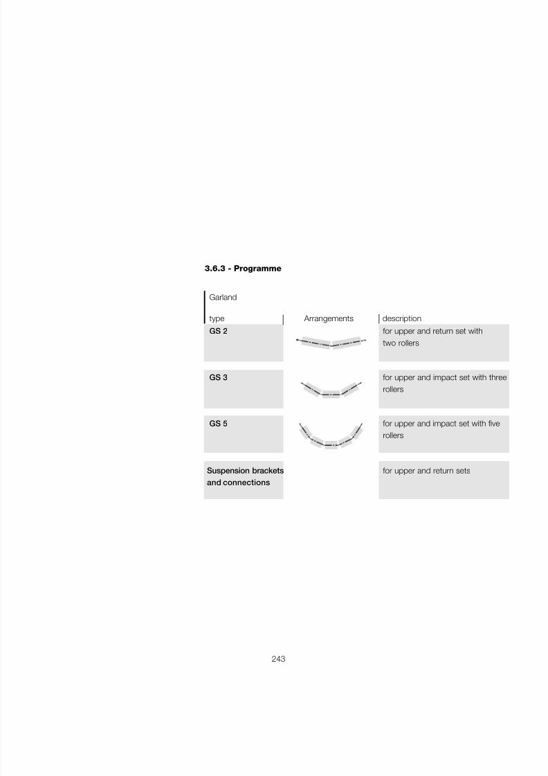
7/27/2019 31801183 Idler Roller
http://slidepdf.com/reader/full/31801183-idler-roller 245/308
243
3.6.3 - Programme
Garland
type Arrangements description
GS 2 for upper and return set withtwo rollers
GS 3 for upper and impact set with threerollers
GS 5 for upper and impact set with fiverollers
Suspension brackets for upper and return setsand connections
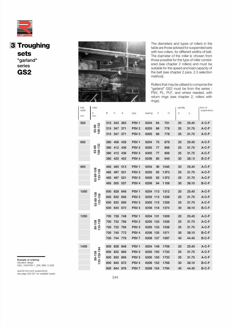
7/27/2019 31801183 Idler Roller
http://slidepdf.com/reader/full/31801183-idler-roller 246/308
3 Troughing
sets
244
®
"garland"series
GS2
The diameters and types of rollers in thetable are those advised for suspended setswith two rollers, for different widths of belt.
The diameter of the roller is chosen fromthose possible for the type of roller consid-ered (see chapter 2 rollers) and must besuitable for the speed and load capacity of the belt (see chapter 2 para. 2.3 selectionmethod).
Rollers that may be utilised to comprise the“garland” GS2 must be from the series :PSV, PL, PLF, and where needed, withreturn rings (see chapter 2, rollers withrings).
Example of orderingstandard designGS2, 1000/PSV 1, 20K, 89N, C=628
specify form and suspensionssee page 250-251 for available types)
belt roller spindle form of width suspensions
D B C A type bearing V O d pmm mm
500 315 343 363 PSV 1 6204 64 751 20 25.40 A-C-F
315 347 371 PSV 2 6205 66 778 25 31.75 A-C-F
315 347 371 PSV 3 6305 66 778 25 31.75 A-C-F
650 380 408 428 PSV 1 6204 75 879 20 25.40 A-C-F
380 412 436 PSV 2 6205 77 906 25 31.75 A-C-F
380 412 436 PSV 3 6305 77 906 25 31.75 A-C-F
380 420 452 PSV 4 6206 80 940 30 38.10 B-C-F
800 465 493 513 PSV 1 6204 90 1046 20 25.40 A-C-F
465 497 521 PSV 2 6205 92 1 073 25 31.75 A-C-F
465 497 521 PSV 3 6305 92 1 073 25 31.75 A-C-F
465 505 537 PSV 4 6206 94 1 108 30 38.10 B-C-F
1000 600 628 648 PSV 1 6204 113 1312 20 25.40 A-C-F
600 632 656 PSV 2 6205 115 1339 25 31.75 A-C-F
600 632 656 PSV 3 6305 115 1339 25 31.75 A-C-F
600 640 672 PSV 4 6206 118 1374 30 38.10 B-C-F
1200 700 728 748 PSV 1 6204 131 1509 20 25.40 A-C-F
700 732 756 PSV 2 6205 133 1536 25 31.75 A-C-F
700 732 756 PSV 3 6305 133 1536 25 31.75 A-C-F
700 740 772 PSV 4 6206 135 1571 30 38.10 B-C-F
700 744 776 PSV 7 6308 137 1597 40 44.45 B-C-F
1400 800 828 848 PSV 1 6204 148 1706 20 25.40 A-C-F
800 832 856 PSV 2 6205 150 1733 25 31.75 A-C-F
800 832 856 PSV 3 6305 150 1733 25 31.75 A-C-F
800 840 872 PSV 4 6206 152 1768 30 38.10 B-C-F
800 844 876 PSV 7 6308 154 1794 40 44.45 B-C-F
6 3
- 8 9
1 0 8
- 1 3 3
6 3
- 8 9
1 0 8
- 1 3 3
6 3
- 8 9
- 1 0 8
1 3 3
- 1 5 9
6 3
- 8 9
- 1 0 8
1 3 3
- 1 5 9
8 9
- 1 0 8
1 3 3 - 1 5 9
8 9
- 1 0 8
1 3 3
- 1 5 9
- 1 9 4
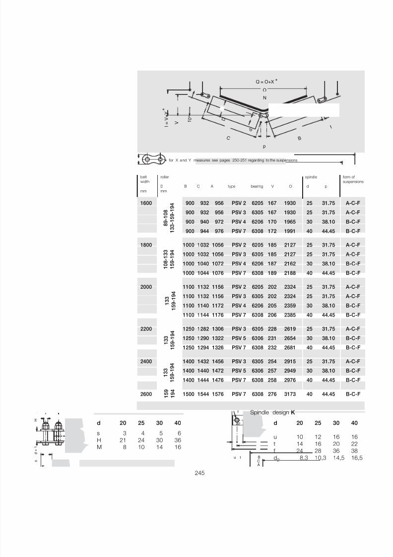
7/27/2019 31801183 Idler Roller
http://slidepdf.com/reader/full/31801183-idler-roller 247/308
245
N
BC
t
p
D
d
O
Q = O+X
V I =
V +
Y
1 0 °
M
d +
1
s
H
d 20 25 30 40
s 3 4 5 6H 21 24 30 36M 8 10 14 16
d 20 25 30 40
u 10 12 16 16t 14 16 20 22f 24 28 36 38d2 8,3 10,3 14,5 16,5
Spindle design K f
u t
A
BC
d2
belt roller spindle form of width suspensions
D B C A type bearing V O d p
mm mm
1600 900 932 956 PSV 2 6205 167 1930 25 31.75 A-C-F
900 932 956 PSV 3 6305 167 1930 25 31.75 A-C-F
900 940 972 PSV 4 6206 170 1965 30 38.10 B-C-F
900 944 976 PSV 7 6308 172 1991 40 44.45 B-C-F
1800 1000 1032 1056 PSV 2 6205 185 2127 25 31.75 A-C-F
1000 1032 1056 PSV 3 6305 185 2127 25 31.75 A-C-F
1000 1040 1072 PSV 4 6206 187 2162 30 38.10 B-C-F
1000 1044 1076 PSV 7 6308 189 2188 40 44.45 B-C-F
2000 1100 1132 1156 PSV 2 6205 202 2324 25 31.75 A-C-F1100 1132 1156 PSV 3 6305 202 2324 25 31.75 A-C-F
1100 1140 1172 PSV 4 6206 205 2359 30 38.10 B-C-F
1100 1144 1176 PSV 7 6308 206 2385 40 44.45 B-C-F
2200 1250 1282 1306 PSV 3 6305 228 2619 25 31.75 A-C-F
1250 1290 1322 PSV 5 6306 231 2654 30 38.10 B-C-F
1250 1294 1326 PSV 7 6308 232 2681 40 44.45 B-C-F
2400 1400 1432 1456 PSV 3 6305 254 2915 25 31.75 A-C-F
1400 1440 1472 PSV 5 6306 257 2949 30 38.10 B-C-F
1400 1444 1476 PSV 7 6308 258 2976 40 44.45 B-C-F
2600 1500 1544 1576 PSV 7 6308 276 3173 40 44.45 B-C-F
8 9
- 1 0 8
1 3 3
- 1 5 9
- 1 9 4
1 0 8
- 1 3 3
1 5 9
- 1 9 4
1 3 3
1 5 9
- 1 9 4
1 3 3
1 5 9
- 1 9 4
1 3 3
1 5 9
- 1 9 4
1 5 9
1 9 4
*
* for X a nd Y measures see pages 250-251 regarding to the suspensions
*
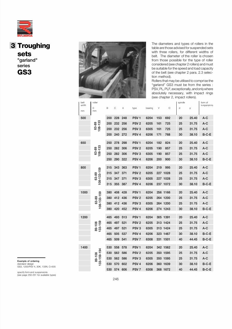
7/27/2019 31801183 Idler Roller
http://slidepdf.com/reader/full/31801183-idler-roller 248/308
3 Troughing
sets
246
®
"garland"series
GS3
The diameters and types of rollers in thetable are those advised for suspended setswith three rollers, for different widths of
belt. The diameter of the roller is chosenfrom those possible for the type of rollerconsidered (see chapter 2 rollers) and mustbe suitable for the speed and load capacityof the belt (see chapter 2 para. 2.3 selec-tion method).Rollers that may be utilised to comprise the“garland” GS3 must be from the series :PSV, PL, PLF, exceptionally, and only whereabsolutely necessary, with impact rings(see chapter 2, impact rollers).
Example of orderingstandard designGS3, 1200/PSV 4, 30K, 133N, C=505
specify form and suspensions(see page 250-251 for available types)
belt roller spindle form of width suspensions
D B C A type bearing V O d pmm mm
500 200 228 248 PSV 1 6204 153 692 20 25.40 A-C
200 232 256 PSV 2 6205 161 725 25 31.75 A-C
200 232 256 PSV 3 6305 161 725 25 31.75 A-C
200 240 272 PSV 4 6206 171 768 30 38.10 B-C-E
650 250 278 298 PSV 1 6204 182 824 20 25.40 A-C
250 282 306 PSV 2 6205 190 857 25 31.75 A-C
250 282 306 PSV 3 6305 190 857 25 31.75 A-C
250 290 322 PSV 4 6206 200 900 30 38.10 B-C-E
800 315 343 363 PSV 1 6204 219 995 20 25.40 A-C
315 347 371 PSV 2 6205 227 1028 25 31.75 A-C
315 347 371 PSV 3 6305 227 1028 25 31.75 A-C
315 355 387 PSV 4 6206 237 1072 30 38.10 B-C-E
1000 380 408 428 PSV 1 6204 256 1166 20 25.40 A-C
380 412 436 PSV 2 6205 264 1200 25 31.75 A-C
380 412 436 PSV 3 6305 264 1200 25 31.75 A-C
380 420 452 PSV 4 6206 274 1243 30 38.10 B-C-E
1200 465 493 513 PSV 1 6204 305 1391 20 25.40 A-C
465 497 521 PSV 2 6205 313 1424 25 31.75 A-C
465 497 521 PSV 3 6305 313 1424 25 31.75 A-C
465 505 537 PSV 4 6206 323 1467 30 38.10 B-C-E
465 509 541 PSV 7 6308 331 1501 40 44.45 B-C-E
1400 530 558 578 PSV 1 6204 342 1562 20 25.40 A-C
530 562 586 PSV 2 6205 350 1595 25 31.75 A-C
530 562 586 PSV 3 6305 350 1595 25 31.75 A-C
530 570 602 PSV 4 6206 360 1639 30 38.10 B-C-E
530 574 606 PSV 7 6308 368 1672 40 44.45 B-C-E
6 3
- 8 9
1 0 8
- 1 3 3
6 3
- 8 9
1 0 8
- 1 3 3
6 3
- 8 9
1 0 8
- 1 3 3
- 1 5 9
6 3
- 8 9
1 0 8
- 1 3 3
- 1 5 9
8 9
- 1
0 8
1 3 3 - 1 5 9
8 9
- 1 0 8
1 3 3
- 1 5 9
- 1 9 4
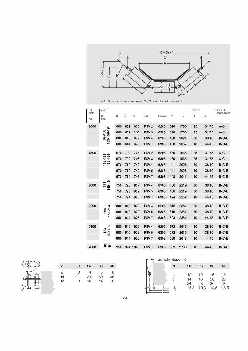
7/27/2019 31801183 Idler Roller
http://slidepdf.com/reader/full/31801183-idler-roller 249/308
247
N
p
C B
t
D d
O
Q = O+X
V I =
V +
Y
3 5 °
*
*
belt roller spindle form of width suspension
D B C A type bearing V O d pmm mm
1600 600 632 656 PSV 2 6205 390 1780 25 31.75 A-C
600 632 6 56 PSV 3 6305 390 1780 25 31.75 A-C
600 640 672 PSV 4 6206 400 1824 30 38.10 B-C-E
600 644 676 PSV 7 6308 408 1857 40 44.45 B-C-E
1800 670 702 726 PSV 2 6205 430 1965 25 31.75 A-C
670 702 7 26 PSV 3 6305 430 1965 25 31.75 A-C
670 710 742 PSV 4 6206 441 2008 30 38.10 B-C-E
670 710 742 PSV 5 6306 441 2008 30 38.10 B-C-E
670 714 746 PSV 7 6308 448 2041 40 44.45 B-C-E
2000 750 790 822 PSV 4 6206 486 2219 30 38.10 B-C-E
750 790 822 PSV 5 6306 486 2219 30 38.10 B-C-E
750 794 826 PSV 7 6308 494 2252 40 44.45 B-C-E
2200 800 840 872 PSV 4 6206 515 2351 30 38.10 B-C-E
800 840 872 PSV 5 6306 515 2351 30 38.10 B-C-E
800 844 876 PSV 7 6308 523 2384 40 44.45 B-C-E
2400 900 940 972 PSV 4 6206 572 2615 30 38.10 B-C-E
900 940 972 PSV 5 6306 572 2615 30 38.10 B-C-E
900 944 976 PSV 7 6308 580 2648 40 44.45 B-C-E
2600 950 994 1026 PSV 7 6308 609 2780 40 44.45 B-C-E
8 9
- 1 0 8
1 3 3
- 1 5 9
- 1 9 4
1 0 8
- 1 3 3
1 5 9
- 1 9 4
1 3 3
1 5 9
- 1 9 4
1 3 3
1 5 9
- 1 9 4
1 3 3
1 5 9
- 1 9 4
1 5 9
1 9 4
M
d +
1
s
H
d 20 25 30 40
s 3 4 5 6H 21 24 30 36M 8 10 14 16
d 20 25 30 40
u 10 12 16 16t 14 16 20 22f 24 28 36 38d2 8,3 10,3 14,5 16,5
Spindle design K f
u t
A
BC
d2
* for X and Y measures see pages 250-251 regarding to the suspensions
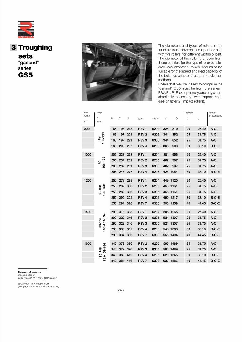
7/27/2019 31801183 Idler Roller
http://slidepdf.com/reader/full/31801183-idler-roller 250/308
3 Troughing
sets
248
®
"garland"series
GS5
The diameters and types of rollers in thetable are those advised for suspended setswith five rollers, for different widths of belt.
The diameter of the roller is chosen fromthose possible for the type of roller consid-ered (see chapter 2 rollers) and must besuitable for the speed and load capacity of the belt (see chapter 2 para. 2.3 selectionmethod).Rollers that may be utilised to comprise the“garland” GS5 must be from the series :PSV, PL, PLF, exceptionally, and only whereabsolutely necessary, with impact rings(see chapter 2, impact rollers).
Example of orderingstandard designGS5, 1600/PSV 7, 40K, 159N,C=384
specify form and suspensions(see page 250-251 for available types)
belt roller spindle form of width suspensions
D B C A type bearing V O d pmm mm
800 165 193 213 PSV 1 6204 326 810 20 25.40 A-C
165 197 221 PSV 2 6205 344 852 25 31.75 A-C
165 197 221 PSV 3 6305 344 852 25 31.75 A-C
165 205 237 PSV 4 6206 368 908 30 38.10 B-C-E
1000 205 233 253 PSV 1 6204 384 956 20 25.40 A-C
205 237 261 PSV 2 6205 402 997 25 31.75 A-C
205 237 261 PSV 3 6305 402 997 25 31.75 A-C
205 245 277 PSV 4 6206 425 1054 30 38.10 B-C-E
1200 250 278 298 PSV 1 6204 449 1120 20 25.40 A-C
250 282 306 PSV 2 6205 466 1161 25 31.75 A-C
250 282 306 PSV 3 6305 466 1161 25 31.75 A-C
250 290 322 PSV 4 6206 490 1217 30 38.10 B-C-E
250 294 326 PSV 7 6308 508 1259 40 44.45 B-C-E
1400 290 318 338 PSV 1 6204 506 1265 20 25.40 A-C
290 322 346 PSV 2 6205 524 1307 25 31.75 A-C
290 322 346 PSV 3 6305 524 1307 25 31.75 A-C
290 330 362 PSV 4 6206 548 1363 30 38.10 B-C-E
290 334 366 PSV 7 6308 565 1404 40 44.45 B-C-E
1600 340 372 396 PSV 2 6205 596 1489 25 31.75 A-C
340 372 396 PSV 3 6305 596 1489 25 31.75 A-C
340 380 412 PSV 4 6206 620 1545 30 38.10 B-C-E
340 384 416 PSV 7 6308 637 1586 40 44.45 B-C-E
8 9
1 0 8
- 1 3 3
8 9
1 0 8
- 1 3 3
8 9
- 1 0 8
1 3 3
- 1 5 9
8 9
- 1 0 8
1 3 3
- 1 5 9
- 1 9 4
8 9
- 1 0 8
1 3 3
- 1 5 9
- 1 9 4
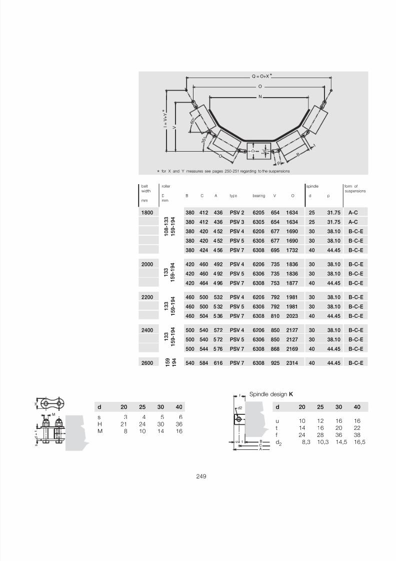
7/27/2019 31801183 Idler Roller
http://slidepdf.com/reader/full/31801183-idler-roller 251/308
249
p
D d
C
N
B
t
O
Q = O+X
V I =
V +
Y
6 0
°
3 5
°
M
d +
1
s
H
d 20 25 30 40
s 3 4 5 6H 21 24 30 36M 8 10 14 16
d 20 25 30 40
u 10 12 16 16t 14 16 20 22f 24 28 36 38d2 8,3 10,3 14,5 16,5
Spindle design K f
u t
A
BC
d2
belt roller spindle form of
width suspensionsD B C A type bearing V O d pmm mm
1800 380 412 436 PSV 2 6205 654 1634 25 31.75 A-C
380 412 436 PSV 3 6305 654 1634 25 31.75 A-C
380 420 4 52 PSV 4 6206 677 1690 30 38.10 B-C-E
380 420 4 52 PSV 5 6306 677 1690 30 38.10 B-C-E
380 424 4 56 PSV 7 6308 695 1732 40 44.45 B-C-E
2000 420 460 492 PSV 4 6206 735 1836 30 38.10 B-C-E
420 460 4 92 PSV 5 6306 735 1836 30 38.10 B-C-E
420 464 4 96 PSV 7 6308 753 1877 40 44.45 B-C-E
2200 460 500 532 PSV 4 6206 792 1981 30 38.10 B-C-E
460 500 5 32 PSV 5 6306 792 1981 30 38.10 B-C-E
460 504 5 36 PSV 7 6308 810 2023 40 44.45 B-C-E
2400 500 540 572 PSV 4 6206 850 2127 30 38.10 B-C-E
500 540 5 72 PSV 5 6306 850 2127 30 38.10 B-C-E
500 544 5 76 PSV 7 6308 868 2169 40 44.45 B-C-E
2600 540 584 616 PSV 7 6308 925 2314 40 44.45 B-C-E
1 0 8
- 1 3 3
1 5 9
- 1 9 4
1 3 3
1 5 9
- 1 9 4
1 3 3
1 5 9
- 1 9 4
1 3 3
1 5 9
- 1 9 4
1 5 9
1 9 4
*
*
* for X and Y measures see pages 250-251 regarding to the suspensions
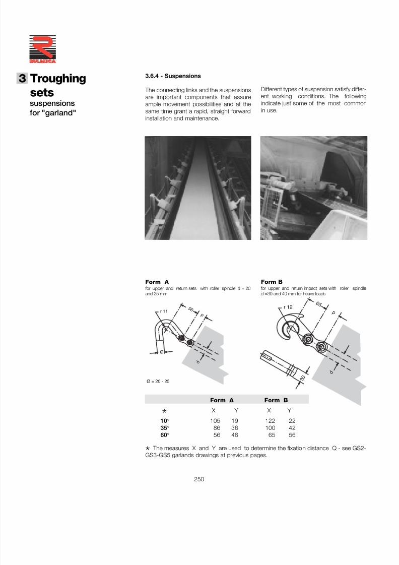
7/27/2019 31801183 Idler Roller
http://slidepdf.com/reader/full/31801183-idler-roller 252/308
3 Troughing
sets
250
®
suspensionsfor "garland"
3.6.4 - Suspensions
The connecting links and the suspensions
are important components that assureample movement possibilities and at thesame time grant a rapid, straight forwardinstallation and maintenance.
Different types of suspension satisfy differ-
ent working conditions. The followingindicate just some of the most commonin use.
5 6
Ø
d
p
Ø = 20 - 25
r 11
d
6 5
p
3 0
r 12
Form Bfor upper and return impact sets with roller spindled =30 and 40 mm for heavy loads
Form A for upper and return sets with roller spindle d = 20and 25 mm
Form A Form B
* X Y X Y
10 ° 105 19 122 22 35 ° 86 36 100 42 60 ° 56 48 65 56
* The measures X and Y are used to determine the fixation distance Q - see GS2-GS3-GS5 garlands drawings at previous pages.
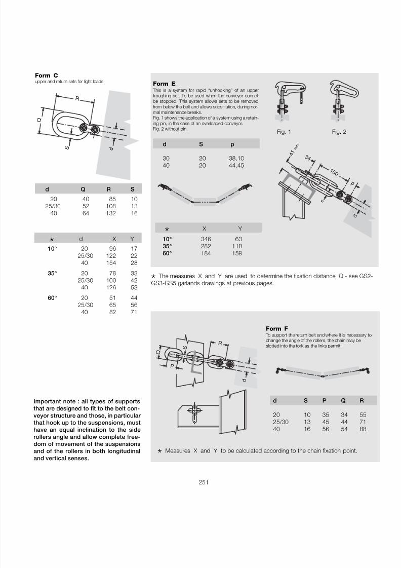
7/27/2019 31801183 Idler Roller
http://slidepdf.com/reader/full/31801183-idler-roller 253/308
251
Form Cupper and return sets for light loads
Q
S
R
d
3 4
1 5 0
p
4 1 m i n .
d
S
Form E This is a system for rapid “unhooking” of an upper
troughing set. To be used when the conveyor cannotbe stopped. This system allows sets to be removedfrom below the belt and allows substitution, during nor-mal maintenance breaks.Fig. 1 shows the application of a system using a retain-ing pin, in the case of an overloaded conveyor.Fig. 2 without pin.
d S p
30 20 38,1040 20 44,45
Fig. 1 Fig. 2
d S P Q R
20 10 35 34 5525/30 13 45 44 7140 16 56 54 88
d
R
Q S
P
* X Y
10 ° 346 63 35 ° 282 118 60 ° 184 159
d Q R S
20 40 85 1025/30 52 108 13
40 64 132 16
* d X Y
10 ° 20 96 1725/30 122 22
40 154 28
35 ° 20 78 3325/30 100 42
40 126 53
60 ° 20 51 4425/30 65 56
40 82 71
* The measures X and Y are used to determine the fixation distance Q - see GS2-GS3-GS5 garlands drawings at previous pages.
* Measures X and Y to be calculated according to the chain fixation point.
Form F To support the return belt and where it is necessary tochange the angle of the rollers, the chain may beslotted into the fork as the links permit.
Important note : all types of supportsthat are designed to fit to the belt con-veyor structure and those, in particular that hook up to the suspensions, musthave an equal inclination to the siderollers angle and allow complete free-dom of movement of the suspensionsand of the rollers in both longitudinaland vertical senses.
7/27/2019 31801183 Idler Roller
http://slidepdf.com/reader/full/31801183-idler-roller 254/308
3 Troughing
sets
252
®

7/27/2019 31801183 Idler Roller
http://slidepdf.com/reader/full/31801183-idler-roller 255/308
253
4 Pulleys
7/27/2019 31801183 Idler Roller
http://slidepdf.com/reader/full/31801183-idler-roller 256/308
254
Pulleys4
®
Summary 4 Pulleys page 253
4.1 Introduction ................................................................ 255
4.2 Dimension of pul leys ............................................... 2564.2.1 Shaft importance ......................................................... 257
4.3 General construction data ..................................... 2584.3.1 Types and designs ...................................................... 259
4.4 Order codes .............................................................. 260
4.5 Programme .............................................................. 2614.5.1 Series USC drive with clampig units............................... 2624.5.2 Series USF idler with clampig units................................ 2644.5.3 Series CUF idler with incorporated bearings .................. 2664.5.4 Screw tension unit ........................................................ 2674.5.5 Special pulleys ..............................................................268
7/27/2019 31801183 Idler Roller
http://slidepdf.com/reader/full/31801183-idler-roller 257/308
255
4.1 - Introduction
Pulleys are dimensioned according to thecharacteristics of each conveyor and maybe designed to meet a great variety of construction methods.
For 40 years Rulmeca has designed andmanufactured pulleys, using materials of the highest quality in a production processemploying advanced technology. This to-gether with the application of the Quality
Assurance system certified to ISO 9001,contributes to the production of high
4 - change direction pulley5 - tension pulley6 - snubbing pulley
1 - drive pulley2 - return pulley
quality products offering dependable, longlifeperformance in the field and appreciablyreducing maintenance costs.
In the following drawings various arrange-ments of traditional belt conveyors areshown, with the pulleys numbered anddescribed according to their function andposition in the belt conveyor layout.
62 6 1
6 1
2
6
62
1
3
5 64
7/27/2019 31801183 Idler Roller
http://slidepdf.com/reader/full/31801183-idler-roller 258/308
256
Pulleys4
®
4.2 - Dimensioning pulleys
According to the position that they occupyin a belt conveyor, the pulleys must with-stand the forces imposed by both belttension and conveyed load.
To be as efficient as possible both forreplacement and for new installation, properselection of pulleys requires the followingdata that allows the determination of theconstruction characteristics and dimens-ions.
The principal data necessary to design apulley comprises the following :
- belt width ;
- diameter of drum in relation to the belttype and characteristics ;
- locking arrangement of the shaft to thepulley (locking ring, key, welding);
- position of pulley (drive,return, snub etc...)
- wrap angle of belt on pulley " α ";
- belt tensions T1, T2 or T3 ;
- distance between the supports andflange of the pulley "a g" ;
- type of lagging as required..
a g
G
B
N
D d α
7/27/2019 31801183 Idler Roller
http://slidepdf.com/reader/full/31801183-idler-roller 259/308
257
Limitation of deflection and rotation
After having sized the diameter of the shaftfor various pulleys, the next selection check is to verify that the deflection of the shaftdoes not exceed allowable values.
In particular the deflection " ft " and theangle of inclination " α t " must respect therelationship:
C 1ft max ≤ ______ α t ≤ ______
3000 1000
(Cpr 2)a g c
ft = _________ [ 3(b+2a g )2- 4a g2 ] ≤ _____
24 xExJ 3000
(Cpr 2 ) 1 α t = ________ a g (c - a g )
≤ ______
2xExJ 1000
where:ag = expressed in mmE = modulus of elasticity of steel
(20600 [daN/mm 2 ])
J = moment of inertia of shaft section (0,0491 D 4 [mm 4 ])
Cpr = load on shaft [daN ]
Upon the request for pulleys with charac-teristics and dimensions different fromthose indicated in this catalogue it is advis-able to supply a dimensioned drawing of the pulley with the required features.
4.2.1 - Shaft importance
Excessive deflection of the pulley shaftconstitutes the major reason for failure of the drum structure.
α t
C
a g a gb
f t
The correct sizing of the shaft is thereforeof the greatest importance and must takeinto account an extra high safety factor.
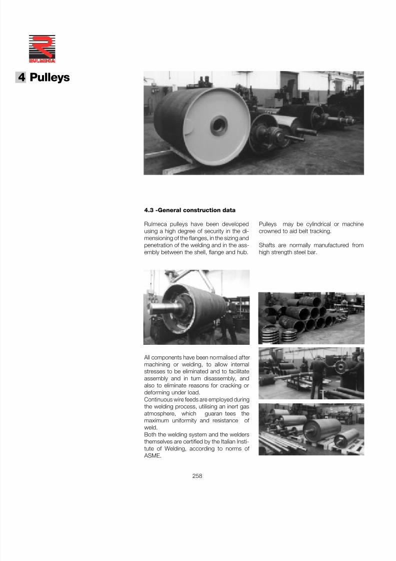
7/27/2019 31801183 Idler Roller
http://slidepdf.com/reader/full/31801183-idler-roller 260/308
258
Pulleys4
®
4.3 -General construction data
Rulmeca pulleys have been developedusing a high degree of security in the di-mensioning of the flanges, in the sizing andpenetration of the welding and in the ass-embly between the shell, flange and hub.
All components have been normalised aftermachining or welding, to allow internalstresses to be eliminated and to facilitateassembly and in turn disassembly, and
also to eliminate reasons for cracking ordeforming under load.Continuous wire feeds are employed duringthe welding process, utilising an inert gasatmosphere, which guaran tees themaximum uniformity and resistance of weld.Both the welding system and the weldersthemselves are certified by the Italian Insti-tute of Welding, according to norms of
ASME.
Pulleys may be cylindrical or machinecrowned to aid belt tracking.
Shafts are normally manufactured fromhigh strength steel bar.
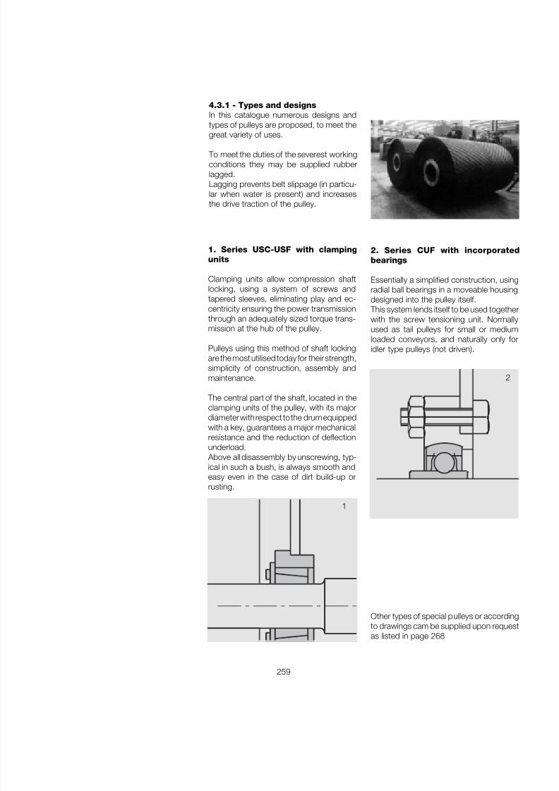
7/27/2019 31801183 Idler Roller
http://slidepdf.com/reader/full/31801183-idler-roller 261/308
259
2. Series CUF with incorporatedbearings
Essentially a simplified construction, usingradial ball bearings in a moveable housingdesigned into the pulley itself.
This system lends itself to be used togetherwith the screw tensioning unit. Normallyused as tail pulleys for small or mediumloaded conveyors, and naturally only foridler type pulleys (not driven).
1. Series USC-USF with clampingunits
Clamping units allow compression shaftlocking, using a system of screws andtapered sleeves, eliminating play and ec-centricity ensuring the power transmissionthrough an adequately sized torque trans-mission at the hub of the pulley.
Pulleys using this method of shaft lockingare the most utilised today for their strength,simplicity of construction, assembly andmaintenance.
The central part of the shaft, located in the
clamping units of the pulley, with its majordiameter with respect to the drum equippedwith a key, guarantees a major mechanicalresistance and the reduction of deflectionunderload.
Above all disassembly by unscrewing, typ-ical in such a bush, is always smooth andeasy even in the case of dirt build-up orrusting.
4.3.1 - Types and designsIn this catalogue numerous designs andtypes of pulleys are proposed, to meet the
great variety of uses.
To meet the duties of the severest workingconditions they may be supplied rubberlagged.Lagging prevents belt slippage (in particu-lar when water is present) and increasesthe drive traction of the pulley.
2
1
Other types of special pulleys or accordingto drawings cam be supplied upon requestas listed in page 268
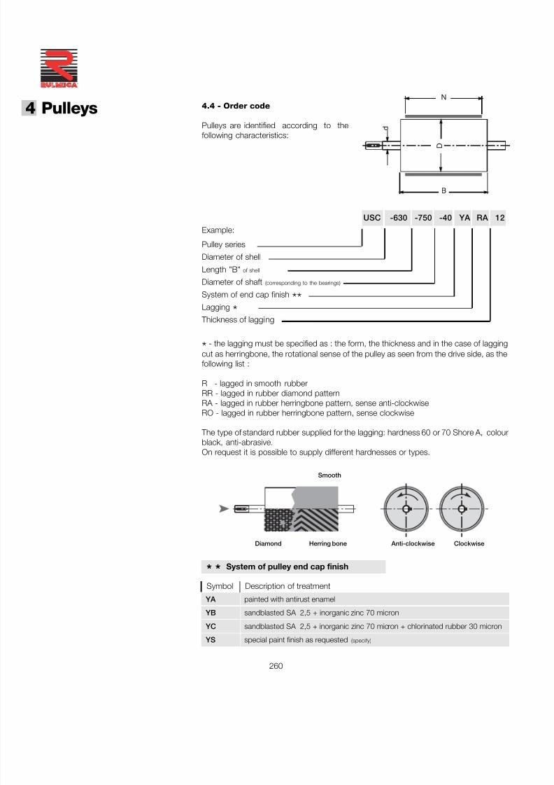
7/27/2019 31801183 Idler Roller
http://slidepdf.com/reader/full/31801183-idler-roller 262/308
260
Pulleys4
®
4.4 - Order code
Pulleys are identified according to the
following characteristics:
B
N
D
d
YA painted with antirust enamel
YB sandblasted SA 2,5 + inorganic zinc 70 micron
YC sandblasted SA 2,5 + inorganic zinc 70 micron + chlorinated rubber 30 micron
YS special paint finish as requested (specify)
* * System of pulley end cap finish
Symbol Description of treatment
USC -630 -750 -40 YA RA 12
Pulley series
Diameter of shell
Length "B" of shell
Diameter of shaft (corresponding to the bearings)
System of end cap finish **Lagging *
Thickness of lagging
Example:
*- the lagging must be specified as : the form, the thickness and in the case of laggingcut as herringbone, the rotational sense of the pulley as seen from the drive side, as thefollowing list :
R - lagged in smooth rubberRR - lagged in rubber diamond pattern
RA - lagged in rubber herringbone pattern, sense anti-clockwiseRO - lagged in rubber herringbone pattern, sense clockwise
The type of standard rubber supplied for the lagging: hardness 60 or 70 Shore A, colourblack, anti-abrasive.On request it is possible to supply different hardnesses or types.
Anti-clockwise ClockwiseHerring bone
Smooth
Diamond
7/27/2019 31801183 Idler Roller
http://slidepdf.com/reader/full/31801183-idler-roller 263/308
261
4.5 - Programme
Pulleys Series Design
type
USC drive pulley with clamping units
USF idler pulley with clamping units
CUF idler pulley with incorporated bearings
TDV screw tension unit simple
Special PULLEY

7/27/2019 31801183 Idler Roller
http://slidepdf.com/reader/full/31801183-idler-roller 264/308
262
Pulleys4
®
Example of orderingstandard designUSC, 800, 1150, 90, YB, RR,12
Serie
USC drive
with clamping units
4.5.1 - Drive pulleys with clamping units
On request pulleys may be supplied withcharacteristics and dimensions differentfrom those indicated in the table or usingthe customer’s drawing.
B
D
N
L
FGK
d
d 1
C = Serie USC mando
UNI 6604
M
For the order code of execution and lag-ging see page 260
The weight stated on the list is referred tothe complete pulley without supports whichcan be supplied upon request.
Pulley with dimensions according to stand-ard NFH 95330
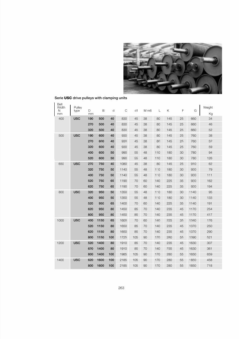
7/27/2019 31801183 Idler Roller
http://slidepdf.com/reader/full/31801183-idler-roller 265/308
263
400 USC 190 500 40 830 45 38 80 145 25 660 34
270 500 40 830 45 38 80 145 25 660 46
320 500 40 830 45 38 80 145 25 660 52
500 USC 190 600 40 930 45 38 80 145 25 760 38
270 600 40 930 45 38 80 145 25 760 52
320 600 40 930 45 38 80 145 25 760 59
400 600 50 990 55 48 110 180 30 780 94
520 600 50 990 55 48 110 180 30 780 126
650 USC 270 750 40 1080 45 38 80 145 25 910 62
320 750 50 1140 55 48 110 180 30 930 79
400 750 50 1140 55 48 110 180 30 930 111520 750 65 1190 70 60 140 225 35 930 162
620 750 65 1190 70 60 140 225 35 930 194
800 USC 320 950 50 1350 55 48 110 180 30 1140 95
400 950 50 1350 55 48 110 180 30 1140 133
520 950 65 1400 70 60 140 225 35 1140 191
620 950 80 1450 85 70 140 235 45 1170 254
800 950 80 1450 85 70 140 235 45 1170 417
1000 USC 400 1150 65 1600 70 60 140 225 35 1340 176
520 1150 80 1650 85 70 140 235 45 1370 250
620 1150 80 1650 85 70 140 235 45 1370 290800 1150 100 1725 105 90 170 280 55 1390 521
1200 USC 520 1400 80 1910 85 70 140 235 45 1630 307
620 1400 80 1910 85 70 140 235 45 1630 361
800 1400 100 1985 105 90 170 280 55 1650 659
1400 USC 620 1600 100 2185 105 90 170 280 55 1850 458
800 1600 100 2185 105 90 170 280 55 1850 718
BeltWidth Pulley WeightN type D B d C d1 M m6 L K F G
mm mm Kg
Serie USC drive pulleys with clamping units
7/27/2019 31801183 Idler Roller
http://slidepdf.com/reader/full/31801183-idler-roller 266/308
264
Pulleys4
®
Serie
USF idler
with clamping units
Example of orderingstandard designUSF, 500, 750, 70, YC, RO, 10
For the order code of execution and lagg-ing see page 260
The weight stated on the list is referred tothe complete pulley without supports whichcam be supplied upon request.
Pulley with dimensions according to stand-ard NFH 95330
FB
D
N
FG
d
d 1
C = Serie USF loco
4.5.2 - Idler pulleys with clamping units
On request pulleys may be supplied withcharacteristics and dimensions differentfrom those indicated in the table or usingthe customer’s drawing.
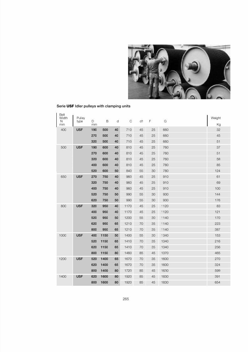
7/27/2019 31801183 Idler Roller
http://slidepdf.com/reader/full/31801183-idler-roller 267/308
265
400 USF 190 500 40 710 45 25 660 32
270 500 40 710 45 25 660 45
320 500 40 710 45 25 660 51
500 USF 190 600 40 810 45 25 760 37
270 600 40 810 45 25 760 51
320 600 40 810 45 25 760 58
400 600 40 810 45 25 780 85
520 600 50 840 55 30 780 124
650 USF 270 750 40 960 45 25 910 61
320 750 40 960 45 25 910 69
400 750 40 960 45 25 910 100
520 750 50 990 55 30 930 144
620 750 50 990 55 30 930 176
800 USF 320 950 40 1170 45 25 1120 83
400 950 40 1170 45 25 1120 121
520 950 50 1200 55 30 1140 170
620 950 65 1210 70 35 1140 223
800 950 65 1210 70 35 1140 387
1000 USF 400 1150 50 1400 55 30 1340 153
520 1150 65 1410 70 35 1340 216620 1150 65 1410 70 35 1340 256
800 1150 80 1460 85 45 1370 465
1200 USF 520 1400 65 1670 70 35 1600 270
620 1400 65 1670 70 35 1600 324
800 1400 80 1720 85 45 1630 599
1400 USF 620 1600 80 1920 85 45 1830 391
800 1600 80 1920 85 45 1830 654
BeltWidth Pulley WeightN type D B d C d1 F G
mm mm Kg
Serie USF Idler pulleys with clamping units
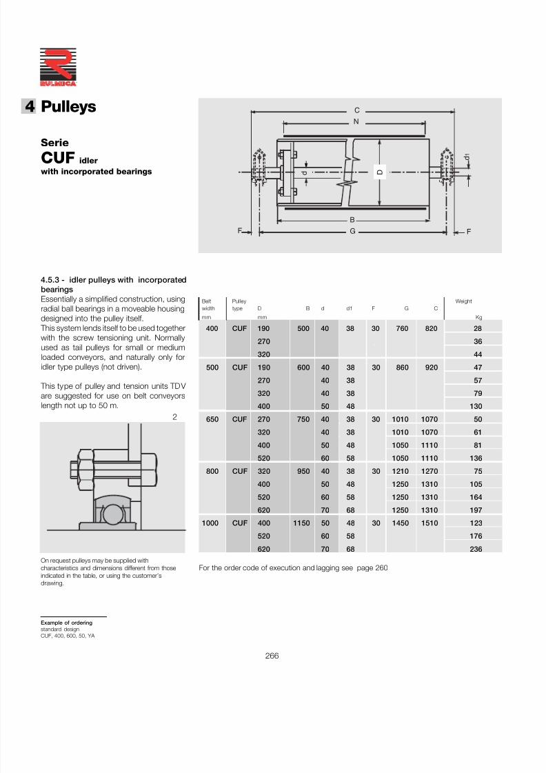
7/27/2019 31801183 Idler Roller
http://slidepdf.com/reader/full/31801183-idler-roller 268/308
266
Pulleys4
®
Serie
CUF idlerwith incorporated bearings
Example of orderingstandard designCUF, 400, 600, 50, YA
B
D
N
FG
d
C
F
d 1
On request pulleys may be supplied withcharacteristics and dimensions different from thoseindicated in the table, or using the customer’sdrawing.
Belt Pulley Weightwidth type D B d d1 F G C
mm mm Kg
400 CUF 190 500 40 38 30 760 820 28
270 36
320 44
500 CUF 190 600 40 38 30 860 920 47
270 40 38 57
320 40 38 79
400 50 48 130
650 CUF 270 750 40 38 30 1010 1070 50
320 40 38 1010 1070 61
400 50 48 1050 1110 81
520 60 58 1050 1110 136
800 CUF 320 950 40 38 30 1210 1270 75
400 50 48 1250 1310 105
520 60 58 1250 1310 164
620 70 68 1250 1310 197
1000 CUF 400 1150 50 48 30 1450 1510 123
520 60 58 176
620 70 68 236
4.5.3 - idler pulleys with incorporatedbearingsEssentially a simplified construction, usingradial ball bearings in a moveable housingdesigned into the pulley itself.
This system lends itself to be used togetherwith the screw tensioning unit. Normallyused as tail pulleys for small or mediumloaded conveyors, and naturally only foridler type pulleys (not driven).
This type of pulley and tension units TDV
are suggested for use on belt conveyorslength not up to 50 m.2
For the order code of execution and lagging see page 260
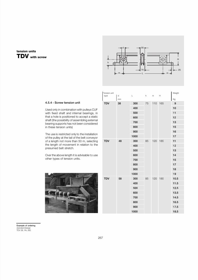
7/27/2019 31801183 Idler Roller
http://slidepdf.com/reader/full/31801183-idler-roller 269/308
267
tension units
TDV with screw
Example of orderingstandard design
TDV 38, YA, 300
4.5.4 - Screw tension unit
Used only in combination with pulleys CUFwith fixed shaft and internal bearings, inthat a hole is positioned to accept a staticshaft (the possibility of assembling externalbearing supports has not been consideredin these tension units)
The use is restricted only to the installationof the pulley at the tail of the belt conveyorof a length not more than 50 m, selecting
the length of movement in relation to thepresumed belt stretch.
Over the above length it is advisable to useother types of tension units.
d
h
m
H
2570
55
Lm
Tension unit Weight
type d L h m Hmm Kg
TDV 38 300 75 110 165 9
400 10
500 11
600 12
700 13
800 15
900 16
1000 17
TDV 48 300 85 120 185 11
400 12
500 13
600 14
700 15
800 17
900 18
1000 19
TDV 58 300 85 120 185 10.5
400 11.5
500 12.5
600 13.5700 14.5
800 16.5
900 17.5
1000 18.5
7/27/2019 31801183 Idler Roller
http://slidepdf.com/reader/full/31801183-idler-roller 270/308
268
Pulleys4
®
54
B
D
N
L
FGK
d
d 1
C
UNI 6604
M
1
B
D
N
L
FGK
d
d 1
C
UNI 6604
M
2
B
D
N
FG
d d 1
C
F
3
4.5.5 - Special pulleysFollowing specific requests and, if poss-ible, a reference drawing provided by the
customer, Rulmeca is able to manufacturedifferent types of special pulleys such as:
Type 1 - pulleys with shaft-to-hub connec-tion by means of key locking device (in-stead of clamping units).
These pulleys, of more traditional design,may have some limitation if compared tothose pulleys having a shaft-to-hubconnection by means of clamping units:lower shaft strength due to the reduceddiameter in the centre and to the groovesfor the keys.Furthermore they have a lower centeringprecision between the shaft and the hubsand, in the frequent case of oxidation, thedisassembly of the two parts can be verydifficult if not impossible.
Type 2 - Pulleys with flanges directly weld-ed to the shaft.
Type 3 - Pulleys without shaft, with flangesand stub axles.
These simplified types of pulleys are suit-able only for light applications and shouldbe used only for deviation, contrast or takeup positions. Continuous service shaftsubstitution should not be foreseen forthese pulleys.
For particular applications, where very wetmaterials are conveyed and the belt innersurface gets very dirty, special pulleys canbe supplied such as:
Type 4 - squirrel cage pulleys Type 5 - wing pulleys
Pulleys according to other types and di-mensions than those described in this cat-alogue can be quoted and manufactured if requested and provided that the customersubmits a drawing.

7/27/2019 31801183 Idler Roller
http://slidepdf.com/reader/full/31801183-idler-roller 271/308
269
5 Belt Cleaners
7/27/2019 31801183 Idler Roller
http://slidepdf.com/reader/full/31801183-idler-roller 272/308
Beltcleaners
5
270
®
Summary 5 Belt cleaners page 269
5.1 Introduction ............................................................... 271
5.2 Selection criteria ....................................................... 272
5.3 Programme ................................................................ 2735.3.1 Belt cleaners type-P ..................................................... 2745.3.2 Belt cleaners type-R .................................................... 2765.3.3 Belt cleaners type-H .................................................... 2785.3.4 Belt cleaners type-U .................................................... 2805.3.5 Belt cleaners simple and plough types........................... 282
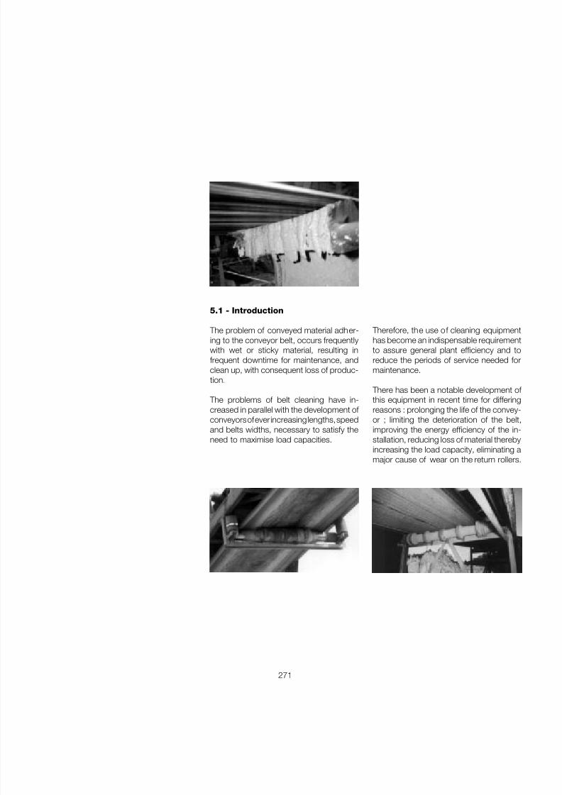
7/27/2019 31801183 Idler Roller
http://slidepdf.com/reader/full/31801183-idler-roller 273/308
271
5.1 - Introduction
The problem of conveyed material adher-ing to the conveyor belt, occurs frequentlywith wet or sticky material, resulting infrequent downtime for maintenance, andclean up, with consequent loss of produc-tion.
The problems of belt cleaning have in-
creased in parallel with the development of conveyors of ever increasing lengths, speedand belts widths, necessary to satisfy theneed to maximise load capacities.
Therefore, the use of cleaning equipmenthas become an indispensable requirementto assure general plant efficiency and toreduce the periods of service needed formaintenance.
There has been a notable development of this equipment in recent time for differing
reasons : prolonging the life of the convey-or ; limiting the deterioration of the belt,improving the energy efficiency of the in-stallation, reducing loss of material therebyincreasing the load capacity, eliminating amajor cause of wear on the return rollers.
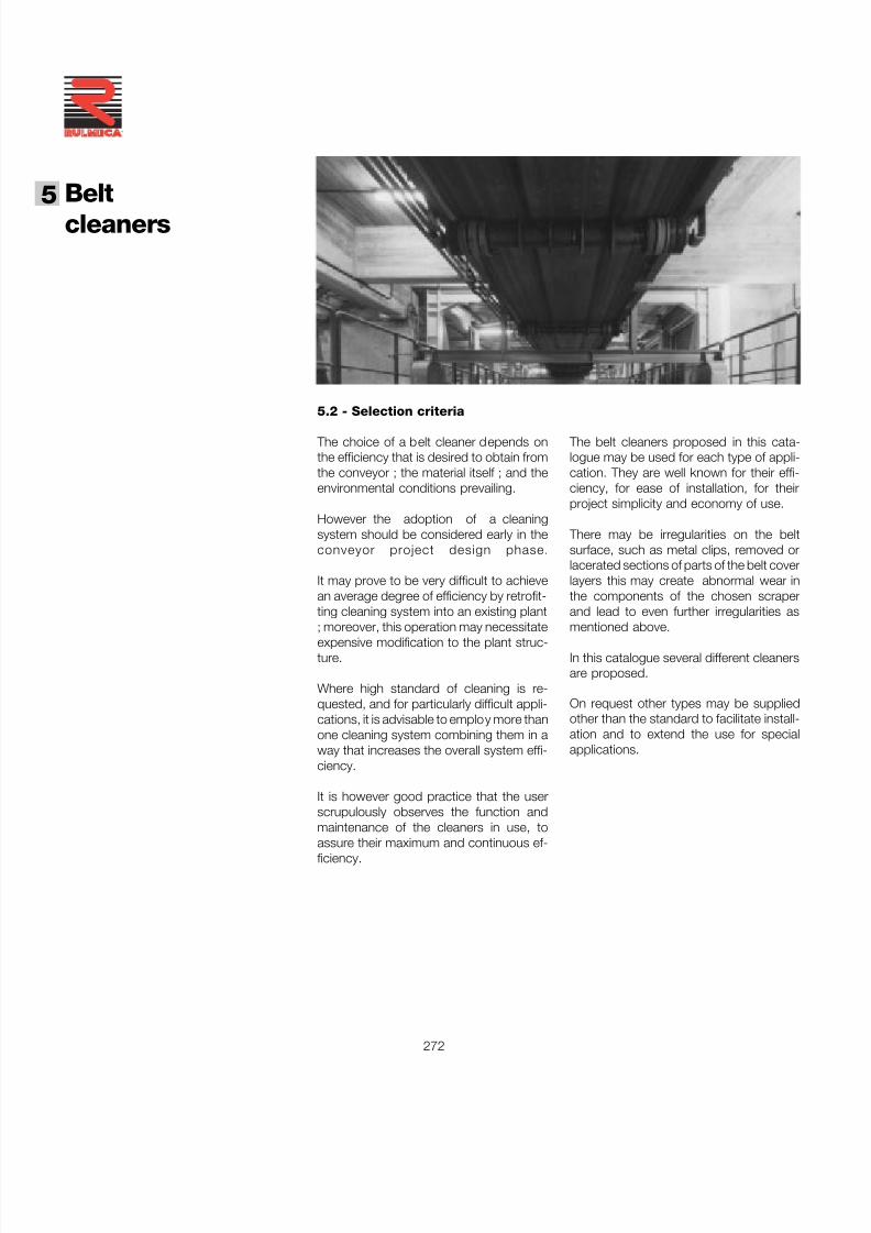
7/27/2019 31801183 Idler Roller
http://slidepdf.com/reader/full/31801183-idler-roller 274/308
Beltcleaners
5
272
®
The belt cleaners proposed in this cata-logue may be used for each type of appli-cation. They are well known for their effi-ciency, for ease of installation, for theirproject simplicity and economy of use.
There may be irregularities on the beltsurface, such as metal clips, removed orlacerated sections of parts of the belt coverlayers this may create abnormal wear inthe components of the chosen scraperand lead to even further irregularities asmentioned above.
In this catalogue several different cleanersare proposed.
5.2 - Selection criteria
The choice of a belt cleaner depends onthe efficiency that is desired to obtain fromthe conveyor ; the material itself ; and theenvironmental conditions prevailing.
However the adoption of a cleaningsystem should be considered early in theconveyor project design phase.
It may prove to be very difficult to achievean average degree of efficiency by retrofit-ting cleaning system into an existing plant; moreover, this operation may necessitateexpensive modification to the plant struc-ture.
Where high standard of cleaning is re-quested, and for particularly difficult appli-cations, it is advisable to employ more thanone cleaning system combining them in away that increases the overall system effi-ciency.
It is however good practice that the userscrupulously observes the function andmaintenance of the cleaners in use, to
assure their maximum and continuous ef-ficiency.
On request other types may be suppliedother than the standard to facilitate install-ation and to extend the use for specialapplications.
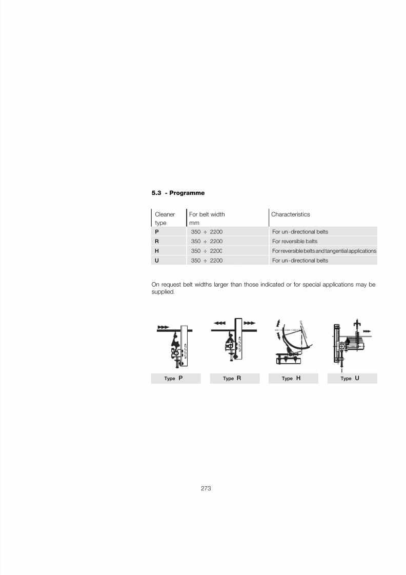
7/27/2019 31801183 Idler Roller
http://slidepdf.com/reader/full/31801183-idler-roller 275/308
273
Cleaner For belt width Characteristicstype mm
P 350 ÷ 2200 For uni-directional belts
R 350 ÷ 2200 For reversible belts
H 350 ÷ 2200 For reversible belts and tangential applications
U 350 ÷ 2200 For uni-directional belts
5.3 - Programme
On request belt widths larger than those indicated or for special applications may besupplied.
Type P Type R Type H Type U
D i a m
e t r o t a m
b u r o
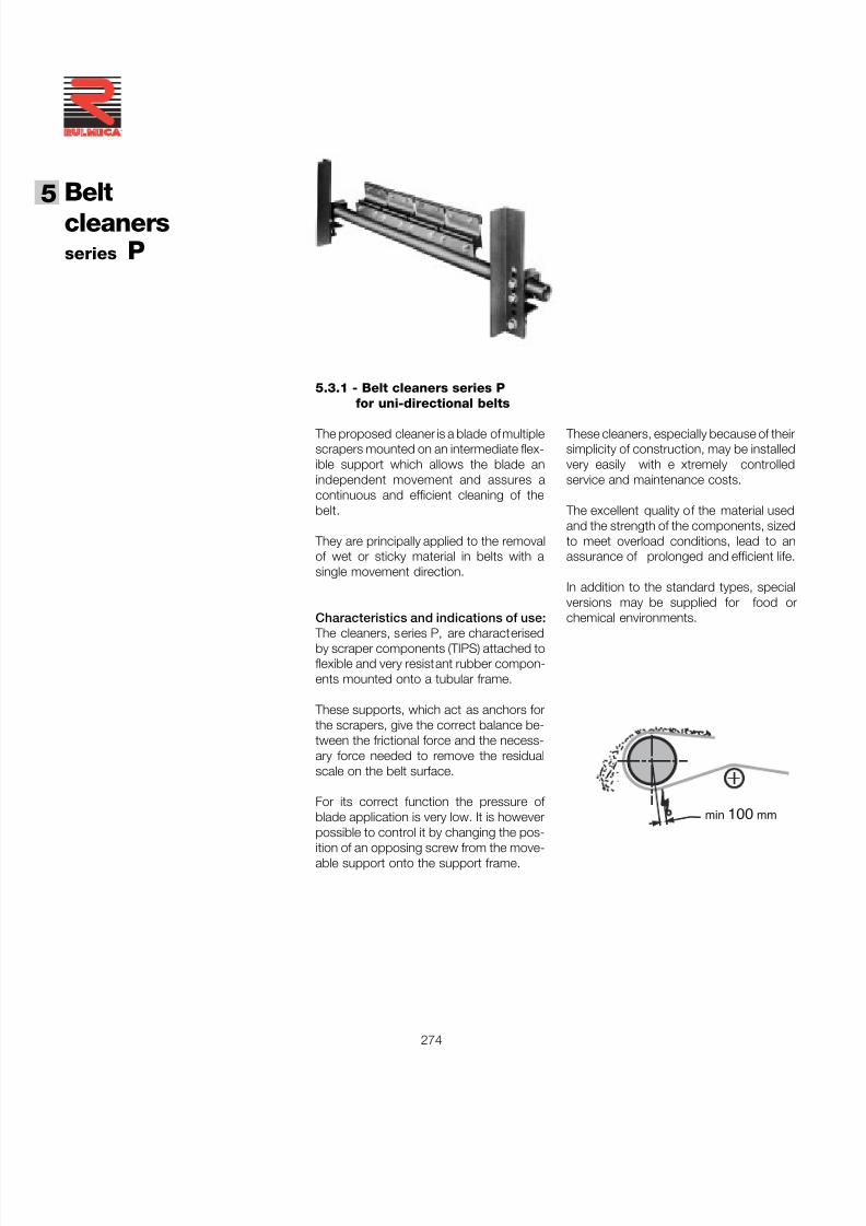
7/27/2019 31801183 Idler Roller
http://slidepdf.com/reader/full/31801183-idler-roller 276/308
Beltcleaners
5
274
®
series P
5.3.1 - Belt cleaners series Pfor uni-directional belts
The proposed cleaner is a blade of multiplescrapers mounted on an intermediate flex-ible support which allows the blade anindependent movement and assures acontinuous and efficient cleaning of thebelt.
They are principally applied to the removalof wet or sticky material in belts with asingle movement direction.
Characteristics and indications of use:
The cleaners, series P, are characterisedby scraper components (TIPS) attached toflexible and very resistant rubber compon-ents mounted onto a tubular frame.
These supports, which act as anchors forthe scrapers, give the correct balance be-tween the frictional force and the necess-ary force needed to remove the residualscale on the belt surface.
For its correct function the pressure of blade application is very low. It is howeverpossible to control it by changing the pos-ition of an opposing screw from the move-able support onto the support frame.
These cleaners, especially because of theirsimplicity of construction, may be installedvery easily with e xtremely controlledservice and maintenance costs.
The excellent quality of the material usedand the strength of the components, sizedto meet overload conditions, lead to anassurance of prolonged and efficient life.
In addition to the standard types, specialversions may be supplied for food orchemical environments.
min 100 mm
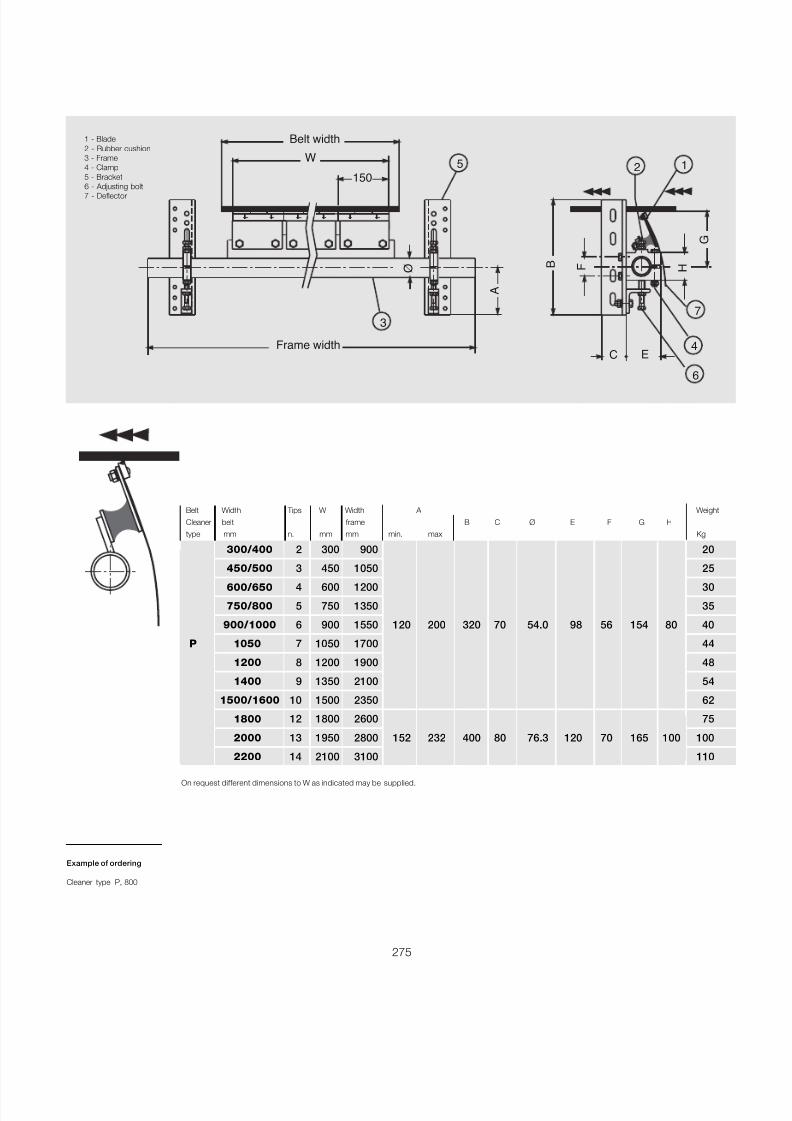
7/27/2019 31801183 Idler Roller
http://slidepdf.com/reader/full/31801183-idler-roller 277/308
275
1 - Blade2 - Rubber cushion3 - Frame4 - Clamp5 - Bracket6 - Adjusting bolt7 - Deflector
Example of ordering
Cleaner type P, 800
5 2 1
7
6
4
3
Belt width
150
W
B
G
H F
C E
Ø
Frame width
A
On request different dimensions to W as indicated may be supplied.
Belt Width Tips W Width A Weight
Cleaner belt frame B C Ø E F G Htype mm n. mm mm min. max Kg
300/400 2 300 900 20
450/500 3 450 1050 25
600/650 4 600 1200 30
750/800 5 750 1350 35
900/1000 6 900 1550 120 200 320 70 54.0 98 56 154 80 40
P 1050 7 1050 1700 44
1200 8 1200 1900 48
1400 9 1350 2100 54
1500/1600 10 1500 2350 62
1800 12 1800 2600 75
2000 13 1950 2800 152 232 400 80 76.3 120 70 165 100 100
2200 14 2100 3100 110
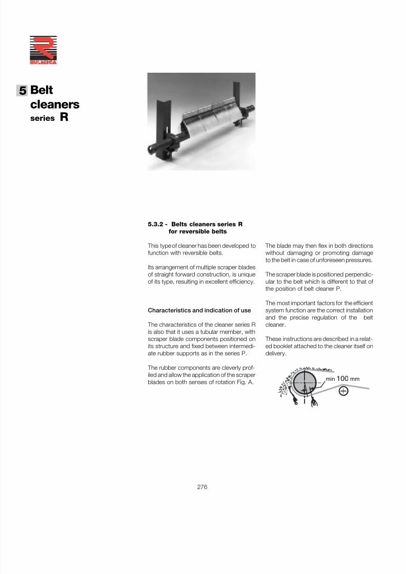
7/27/2019 31801183 Idler Roller
http://slidepdf.com/reader/full/31801183-idler-roller 278/308
Beltcleaners
5
276
®
5.3.2 - Belts cleaners series Rfor reversible belts
This type of cleaner has been developed tofunction with reversible belts.
Its arrangement of multiple scraper bladesof straight forward construction, is uniqueof its type, resulting in excellent efficiency.
Characteristics and indication of use
The characteristics of the cleaner series Ris also that it uses a tubular member, withscraper blade components positioned onits structure and fixed between intermedi-ate rubber supports as in the series P.
The rubber components are cleverly prof-iled and allow the application of the scraperblades on both senses of rotation Fig. A.
The blade may then flex in both directionswithout damaging or promoting damageto the belt in case of unforeseen pressures.
The scraper blade is positioned perpendic-ular to the belt which is different to that of the position of belt cleaner P.
The most important factors for the efficientsystem function are the correct installationand the precise regulation of the beltcleaner.
These instructions are described in a relat-ed booklet attached to the cleaner itself ondelivery.
min 100 mm
series R
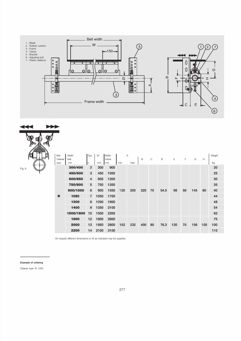
7/27/2019 31801183 Idler Roller
http://slidepdf.com/reader/full/31801183-idler-roller 279/308
277
1 - Blade2 - Rubber cushion3 - Frame4 - Clamp5 - Bracket
6 - Adjusting bolt7 - Plastic deflector
Fig. A
Example of ordering
Cleaner type R, 1200
On request different dimensions to W as indicated may be supplied.
Belt Width Tips W Width A WeightCleaner belt frame B C Ø E F G Htype mm n. mm mm min. max Kg
300/400 2 300 900 20
450/500 3 450 1050 25
600/650 4 600 1200 30
750/800 5 750 1350 35
900/1000 6 900 1550 120 200 320 70 54.0 98 56 145 80 40
R 1050 7 1050 1700 44
1200 8 1200 1900 48
1400 9 1350 2100 54
1500/1600 10 1500 2350 62
1800 12 1800 2600 75
2000 13 1950 2800 152 232 400 80 76.3 120 70 156 100 100
2200 14 2100 3100 110
5 21 7
6
43
Belt width
150
W
B
G
H F
C E
Ø
A
Frame width
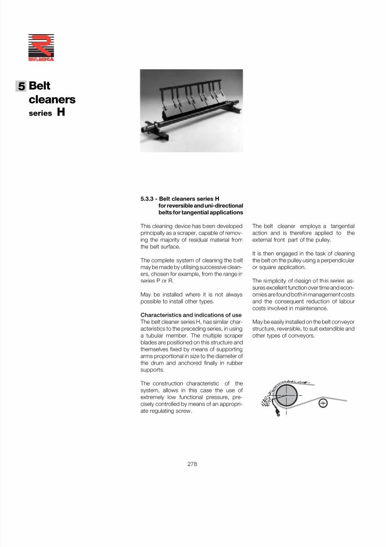
7/27/2019 31801183 Idler Roller
http://slidepdf.com/reader/full/31801183-idler-roller 280/308
Beltcleaners
5
278
®
5.3.3 - Belt cleaners series Hfor reversible and uni-directionalbelts for tangential applications
This cleaning device has been developedprincipally as a scraper, capable of remov-ing the majority of residual material fromthe belt surface.
The complete system of cleaning the beltmay be made by utilising successive clean-ers, chosen for example, from the range in
series P or R.
May be installed where it is not alwayspossible to install other types.
Characteristics and indications of use The belt cleaner series H, has similar char-acteristics to the preceding series, in usinga tubular member. The multiple scraperblades are positioned on this structure andthemselves fixed by means of supportingarms proportional in size to the diameter of the drum and anchored finally in rubbersupports.
The construction characteristic of thesystem, allows in this case the use of extremely low functional pressure, pre-cisely controlled by means of an appropri-ate regulating screw.
The belt cleaner employs a tangentialaction and is therefore applied to theexternal front part of the pulley.
It is then engaged in the task of cleaningthe belt on the pulley using a perpendicularor square application.
The simplicity of design of this series as-sures excellent function over time and econ-omies are found both in management costsand the consequent reduction of labourcosts involved in maintenance.
May be easily installed on the belt conveyorstructure, reversible, to suit extendible andother types of conveyors.
series H
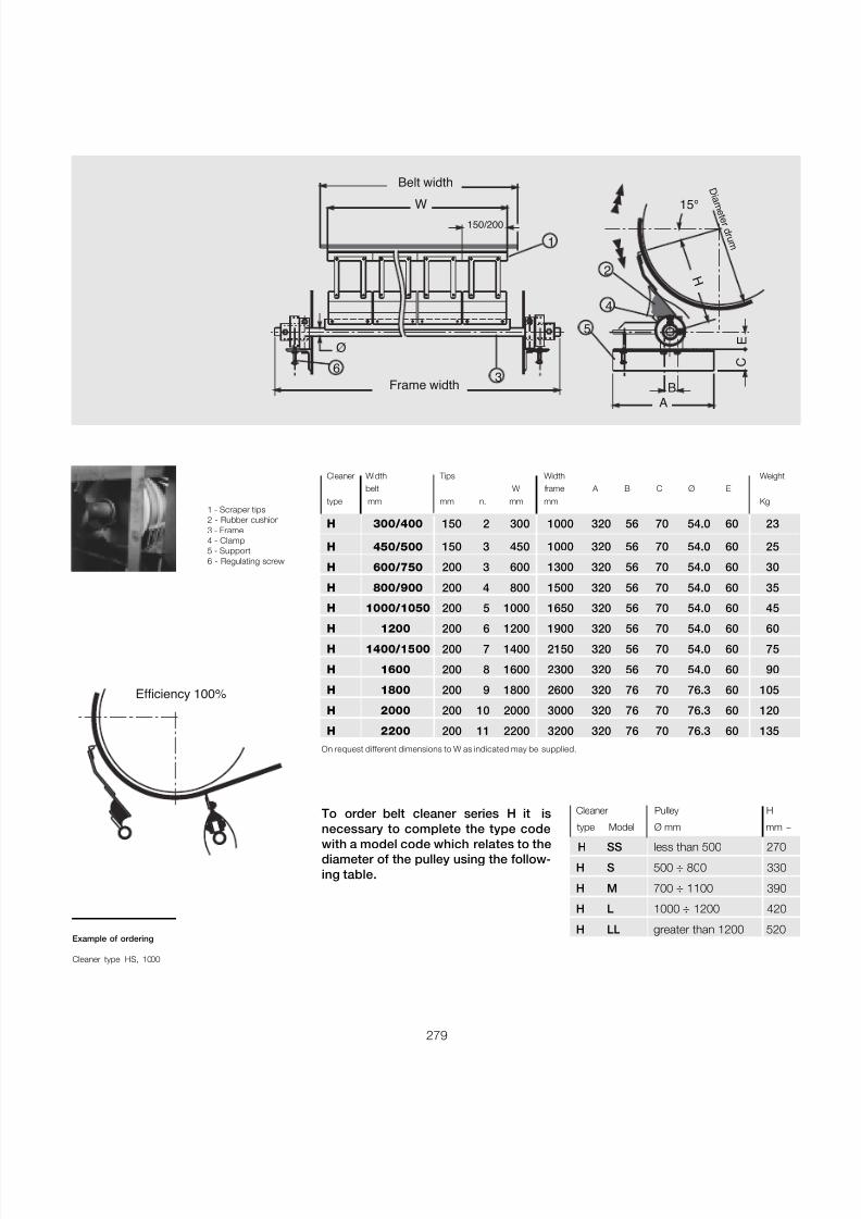
7/27/2019 31801183 Idler Roller
http://slidepdf.com/reader/full/31801183-idler-roller 281/308
279
Ø
150/200W
E
C
BA
H
15°
D i a m e t e r d r u m
2
1
3
4
5
6
Belt width
Frame width
1 - Scraper tips2 - Rubber cushion3 - Frame4 - Clamp5 - Support6 - Regulating screw
Cleaner Width Tips Width Weightbelt W frame A B C Ø E
type mm mm n. mm mm Kg
H 300/400 150 2 300 1000 320 56 70 54.0 60 23
H 450/500 150 3 450 1000 320 56 70 54.0 60 25
H 600/750 200 3 600 1300 320 56 70 54.0 60 30
H 800/900 200 4 800 1500 320 56 70 54.0 60 35
H 1000/1050 200 5 1000 1650 320 56 70 54.0 60 45
H 1200 200 6 1200 1900 320 56 70 54.0 60 60H 1400/1500 200 7 1400 2150 320 56 70 54.0 60 75
H 1600 200 8 1600 2300 320 56 70 54.0 60 90
H 1800 200 9 1800 2600 320 76 70 76.3 60 105
H 2000 200 10 2000 3000 320 76 70 76.3 60 120
H 2200 200 11 2200 3200 320 76 70 76.3 60 135On request different dimensions to W as indicated may be supplied.
Efficiency 100%
To order belt cleaner series H it isnecessary to complete the type codewith a model code which relates to thediameter of the pulley using the follow-ing table.
Cleaner Pulley H
type Model Ø mm mm ~
H SS less than 500 270
H S 500 ÷ 800 330
H M 700 ÷ 1100 390
H L 1000 ÷ 1200 420
H LL greater than 1200 520Example of ordering
Cleaner type HS, 1000
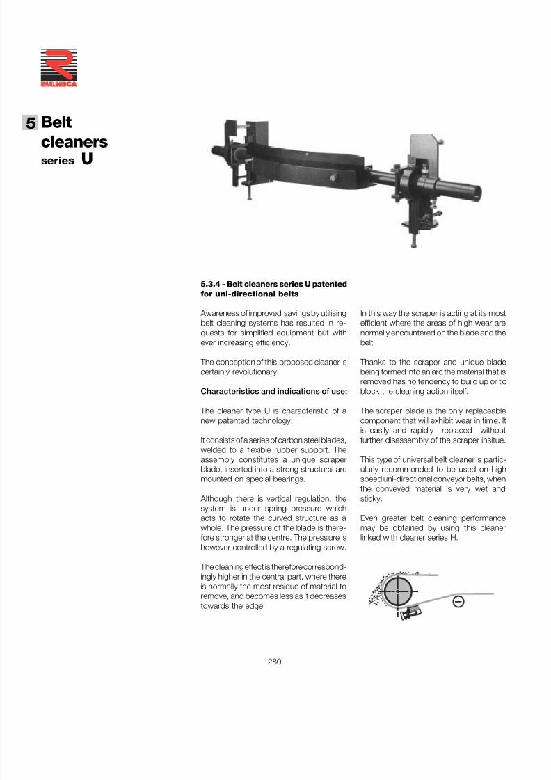
7/27/2019 31801183 Idler Roller
http://slidepdf.com/reader/full/31801183-idler-roller 282/308
Beltcleaners
5
280
®
5.3.4 - Belt cleaners series U patentedfor uni-directional belts
Awareness of improved savings by utilisingbelt cleaning systems has resulted in re-quests for simplified equipment but withever increasing efficiency.
The conception of this proposed cleaner iscertainly revolutionary.
Characteristics and indications of use:
The cleaner type U is characteristic of anew patented technology.
It consists of a series of carbon steel blades,welded to a flexible rubber support. Theassembly constitutes a unique scraperblade, inserted into a strong structural arcmounted on special bearings.
Although there is vertical regulation, thesystem is under spring pressure whichacts to rotate the curved structure as awhole. The pressure of the blade is there-fore stronger at the centre. The pressure ishowever controlled by a regulating screw.
The cleaning effect is therefore correspond-ingly higher in the central part, where thereis normally the most residue of material toremove, and becomes less as it decreasestowards the edge.
In this way the scraper is acting at its mostefficient where the areas of high wear arenormally encountered on the blade and thebelt.
Thanks to the scraper and unique bladebeing formed into an arc the material that isremoved has no tendency to build up or toblock the cleaning action itself.
The scraper blade is the only replaceablecomponent that will exhibit wear in time. Itis easily and rapidly replaced withoutfurther disassembly of the scraper insitue.
This type of universal belt cleaner is partic-ularly recommended to be used on highspeed uni-directional conveyor belts, whenthe conveyed material is very wet andsticky.
Even greater belt cleaning performancemay be obtained by using this cleanerlinked with cleaner series H.
series U
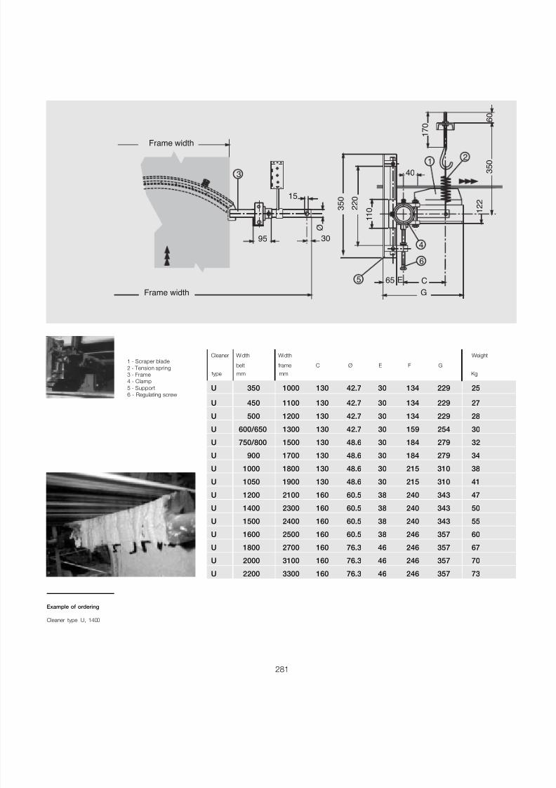
7/27/2019 31801183 Idler Roller
http://slidepdf.com/reader/full/31801183-idler-roller 283/308
281
15
30
Frame width
Frame width
Ø
3
95
65 E C
G
1 2 2
3 5 0
12
4
6
5
2 2 0
1 1 0
3 5 0
6 0
1 7 0
40
1 - Scraper blade2 - Tension spring3 - Frame4 - Clamp5 - Support6 - Regulating screw
Cleaner Width Width Weight
belt frame C Ø E F Gtype mm mm Kg
U 350 1000 130 42.7 30 134 229 25
U 450 1100 130 42.7 30 134 229 27U 500 1200 130 42.7 30 134 229 28
U 600/650 1300 130 42.7 30 159 254 30
U 750/800 1500 130 48.6 30 184 279 32
U 900 1700 130 48.6 30 184 279 34
U 1000 1800 130 48.6 30 215 310 38
U 1050 1900 130 48.6 30 215 310 41
U 1200 2100 160 60.5 38 240 343 47
U 1400 2300 160 60.5 38 240 343 50
U 1500 2400 160 60.5 38 240 343 55
U 1600 2500 160 60.5 38 246 357 60
U 1800 2700 160 76.3 46 246 357 67
U 2000 3100 160 76.3 46 246 357 70
U 2200 3300 160 76.3 46 246 357 73
Example of ordering
Cleaner type U, 1400
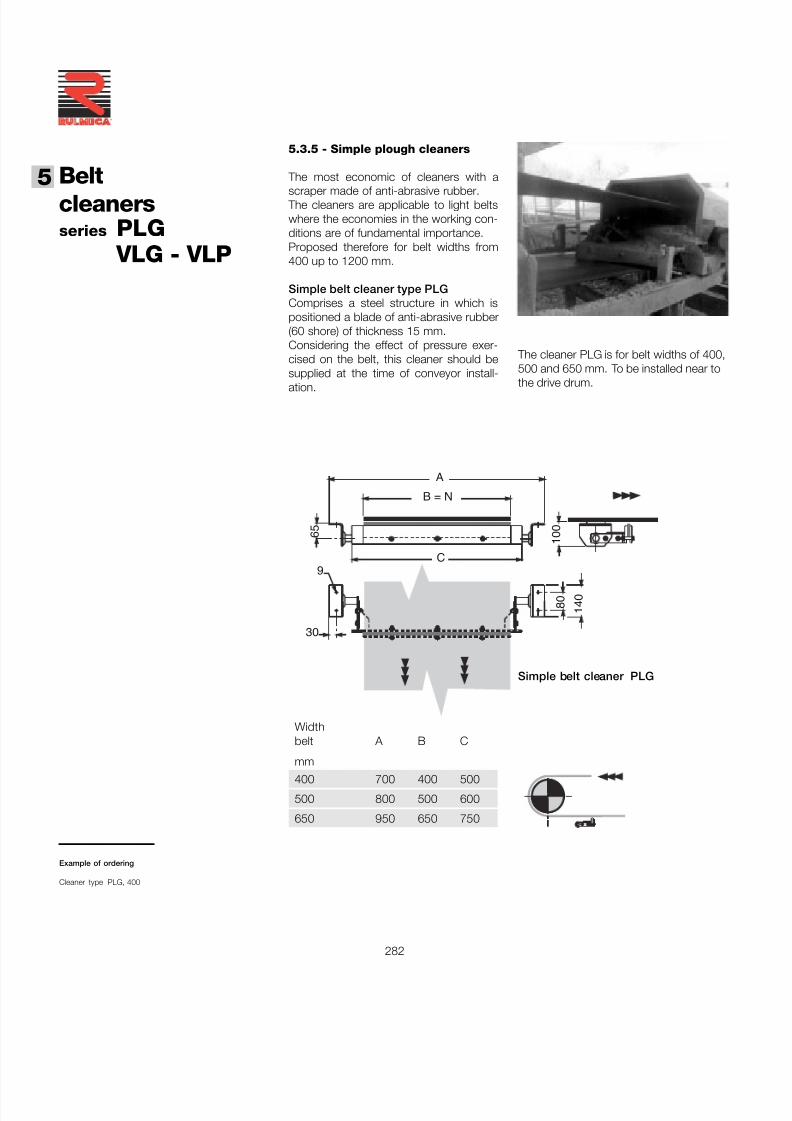
7/27/2019 31801183 Idler Roller
http://slidepdf.com/reader/full/31801183-idler-roller 284/308
Beltcleaners
5
282
®
5.3.5 - Simple plough cleaners
The most economic of cleaners with a
scraper made of anti-abrasive rubber. The cleaners are applicable to light beltswhere the economies in the working con-ditions are of fundamental importance.Proposed therefore for belt widths from400 up to 1200 mm.
Simple belt cleaner type PLGComprises a steel structure in which ispositioned a blade of anti-abrasive rubber(60 shore) of thickness 15 mm.Considering the effect of pressure exer-cised on the belt, this cleaner should besupplied at the time of conveyor install-ation.
B = N
A
C
6 5
1 0 0
8 0
1 4 0
30
9
The cleaner PLG is for belt widths of 400,500 and 650 mm. To be installed near to
the drive drum.
Widthbelt A B C
mm
400 700 400 500
500 800 500 600
650 950 650 750
Simple belt cleaner PLG
series PLGVLG - VLP
Example of ordering
Cleaner type PLG, 400
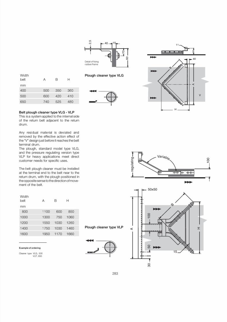
7/27/2019 31801183 Idler Roller
http://slidepdf.com/reader/full/31801183-idler-roller 285/308
283
Belt plough cleaner type VLG - VLP This is a system applied to the internal sideof the return belt adjacent to the returndrum.
Any residual material is deviated andremoved by the effective action effect of the “V” design just before it reaches the beltterminal drum.
The plough, standard model type VLG,and the pressure regulating version type
VLP for heavy applications meet directcustomer needs for specific uses.
The belt plough cleaner must be installedat the terminal end to the belt near to thereturn drum, with the plough positioned inthe opposite sense to the direction of move-ment of the belt.
Widthbelt A B H
mm
400 500 350 360
500 600 420 410
650 740 525 480
Plough cleaner type VLP
Va r i a b l e
r e g u
l a t i n g
A H
B
15
1 0 0
50x50
3 0
5 0
Plough cleaner type VLG
1 0 0
40
A
H
V
B
1140 15 2
, 5
2 3
6 0
Detail of fixingrubber/frame
Example of ordering
Cleaner type VLG, 500VLP, 650
Widthbelt A B H
mm
800 1100 600 850
1000 1300 750 1060
1200 1550 1030 1260
1400 1750 1030 1460
1600 1950 1170 1660

7/27/2019 31801183 Idler Roller
http://slidepdf.com/reader/full/31801183-idler-roller 286/308
Beltcleaners
5
284
®

7/27/2019 31801183 Idler Roller
http://slidepdf.com/reader/full/31801183-idler-roller 287/308
285
6 Covers
7/27/2019 31801183 Idler Roller
http://slidepdf.com/reader/full/31801183-idler-roller 288/308
Covers6
286
®
Summary 6 Covers page 285
6.1 Introduction and methods of use .............................. 287
6.2 Styles and characteristics ......................................... 287
6.3 Programme of plastic covers ................................... 289
6.3.1 Installation method ....................................................... 2906.4 Programme of stee l covers ........................................ 2936.4.1 Installation methodand fixing accessories ..................... 294
7/27/2019 31801183 Idler Roller
http://slidepdf.com/reader/full/31801183-idler-roller 289/308
287
6.1 - Introduction and methods
In the project design of a belt conveyor,after having defined the components of primary importance, it is important to con-sider other accessories such as covers forthe conveyor.
The necessity to protect belt conveyorsmay arise from the weather, from the vola-tile characteristics of the conveyed materi-al, or from the type of works plant, and alsofrom European norms that require the cov-ering of the total length of a belt conveyorin the open.
For example rain may create a problem of belt slip on the drums causing a trackingproblem.Extreme temperatures may cause the plantto mal-function or stop, whilst very strongwind may move the conveyor belt off its
natural position causing serious problemsto the business or loss of conveyed mate-rial.
6.2 - Styles and characteristics
Belt conveyors covers do not require main-tenance and are very easy to install andmove around.
The fixing system is designed in a way thatallows quick and easy relocation of thecovers to facilitate the inspection of theconveyor.
There are two styles of covers that areproposed : those in pre-formed PVC andthose in corrugated galvanised sheet steel.
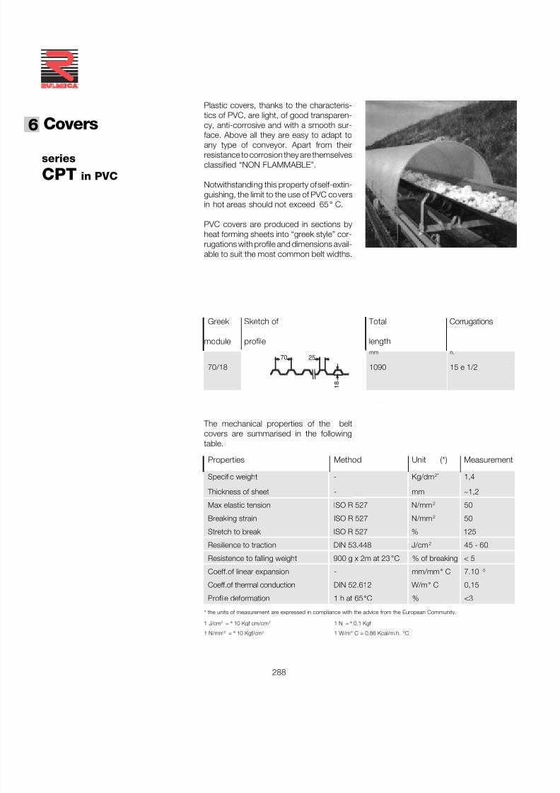
7/27/2019 31801183 Idler Roller
http://slidepdf.com/reader/full/31801183-idler-roller 290/308
Covers6
288
®
series
CPT in PVC
Greek Sketch of Total Corrugations
module profile lengthmm n.
70/18 1090 15 e 1/2
The mechanical properties of the beltcovers are summarised in the followingtable.
70 25
1 8
Properties Method Unit (*) Measurement
Specific weight - Kg/dm 2" 1,4
Thickness of sheet - mm ~1,2
Max elastic tension ISO R 527 N/mm 2 50
Breaking strain ISO R 527 N/mm 2 50
Stretch to break ISO R 527 % 125
Resilience to traction DIN 53.448 J/cm 2 45 - 60Resistence to falling weight 900 g x 2m at 23 °C % of breaking < 5
Coeff.of linear expansion - mm/mm ° C 7.10 -5
Coeff.of thermal conduction DIN 52.612 W/m ° C 0,15
Profile deformation 1 h at 65 °C % <3
* the units of measurement are expressed in compliance with the advice from the European Community.
1 J/cm 2 = ª 10 Kgf cm/cm 2 1 N = ª 0.1 Kgf
1 N/mm 2 = ª 10 Kgf/cm 2 1 W/m ° C = 0.86 Kcal/m.h. °C
Plastic covers, thanks to the characteris-tics of PVC, are light, of good transparen-cy, anti-corrosive and with a smooth sur-
face. Above all they are easy to adapt toany type of conveyor. Apart from theirresistance to corrosion they are themselvesclassified “NON FLAMMABLE”.
Notwithstanding this property of self-extin-guishing, the limit to the use of PVC coversin hot areas should not exceed 65 ° C.
PVC covers are produced in sections byheat forming sheets into “greek style” cor-rugations with profile and dimensions avail-able to suit the most common belt widths.
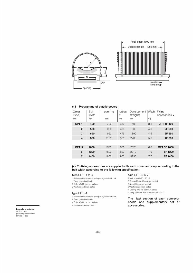
7/27/2019 31801183 Idler Roller
http://slidepdf.com/reader/full/31801183-idler-roller 291/308
289
type CPT -1-2-31 Stainless steel strap and spring with galvanised hook 1 Fixed galvanised hook 2 Bolts M8x20 cadmium plated
2 Washers cadmium plated
type CPT -42 Stainless steel strap and spring with galvanised hook 2 Fixed galvanised hooks4 Bolts M8x20 cadmium plated
4 Washers cadmium plated
type CPT -5-6-72 Arch in profile 20 x 20 x 26 Screws M 6 x 35 cadmium plated4 Nuts M6 cadmium plated
6 Washers cadmium plated4 Locking ruts M6 cadmium plated2 Fixing brackets 30 x 40 in zinc plated steel
The last section of each conveyor needs one supplementary set ofaccessories.
Cover Belt opening radius Development Weight FixingType width r straights accessories *mm mm mm mm mm Kg
CPT 1 400 700 350 1500 3.6 CPT 1F 400
2 500 800 400 1660 4.0 2F 500
3 650 950 475 1890 4.5 3F 650
4 800 1150 575 2200 5.3 4F 800
CPT 5 1000 1350 675 2520 6.0 CPT 5F 1000
6 1200 1600 800 2910 7.0 6F 1200
7 1400 1800 900 3230 7.7 7F 1400
6.3 - Programme of plastic covers
(∗ )(∗ )(∗ )(∗ )(∗ ) To fixing accessories are supplied with each cover and vary according to thebelt width according to the following specification :
gap
r
2 0 0
N
opening
Actal length 1090 mm
Useable length ~ 1050 mm
stainlesssteel strap
Example of orderingCPT 5, 1000plus fixing accessoriesCPT 5F, 1000
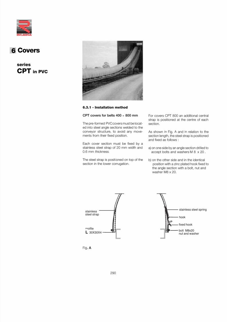
7/27/2019 31801183 Idler Roller
http://slidepdf.com/reader/full/31801183-idler-roller 292/308
Covers6
290
®
series
CPT in PVC
6.3.1 - Installation method
CPT covers for belts 400 ÷ 800 mm
The pre-formed PVC covers must be locat-ed into steel angle sections welded to theconveyor structure, to avoid any move-ments from their fixed position.
Each cover section must be fixed by astainless steel strap of 20 mm width and0.6 mm thickness.
The steel strap is posit ioned on top of thesection in the lower corrugation.
For covers CPT 800 an additional centralstrap is positioned at the centre of eachsection.
As shown in Fig. A and in relation to thesection length, the steel strap is positionedand fixed as follows :
a) on one side by an angle section dril led toaccept bolts and washers M 8 x 20 .
b) on the other side and in the identicalposition with a zinc plated hook fixed tothe angle section with a bolt, nut andwasher M8 x 20.
Fig. A
stainlesssteel strap
stainless steel spring
hook
nut and washerbolt M8x20
fixed hookprofileL 30X30X4
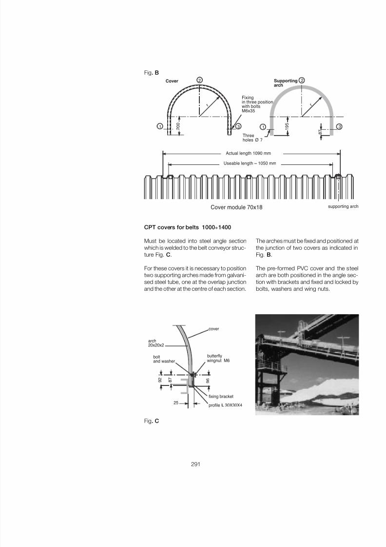
7/27/2019 31801183 Idler Roller
http://slidepdf.com/reader/full/31801183-idler-roller 293/308
291
Fig. B
CPT covers for belts 1000 ÷1400
Must be located into steel angle sectionwhich is welded to the belt conveyor struc-ture Fig. C .
For these covers it is necessary to positiontwo supporting arches made from galvani-
sed steel tube, one at the overlap junctionand the other at the centre of each section.
The arches must be fixed and positioned atthe junction of two covers as indicated inFig. B.
The pre-formed PVC cover and the steelarch are both positioned in the angle sec-
tion with brackets and fixed and locked bybolts, washers and wing nuts.
cover
arch20x20x2
profile L 30X30X4
fixing bracket
wingnut M6butterflybolt
and washer
9 2
8 7
25
9 6
Fig. C
Cover
2 0 0
r r
Fixingin three positionwith boltsM6x35
Supportingarch
Threeholes Ø 7
8 7
1 9 5
Actual length 1090 mm
Useable length ~ 1050 mm
Cover module 70x18 supporting arch
2 2
1 1 33
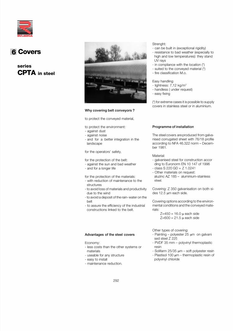
7/27/2019 31801183 Idler Roller
http://slidepdf.com/reader/full/31801183-idler-roller 294/308
Covers6
292
®
series
CPTA in steel
Why covering belt conveyors ?
to protect the conveyed material,
to protect the environment:- against dust- against noise- and for a better integration in the
landscape
for the operators’ safety,
for the protection of the belt:- against the sun and bad weather- and for a longer life
for the protection of the materials:- with reduction of maintenance to the
structures- to avoid loss of materials and productivity
due to the wind- to avoid a deposit of the rain-water on the
belt- to assure the efficiency of the industrial
constructions linked to the belt.
Advantages of the steel covers
Economy:- less costs than the other systems or
materials- useable for any structure- easy to install- maintenance reduction.
Strenght:- can be built in (exceptional rigidity)- resistance to bad weather (especially to
high and low temperatures): they standUV rays
- in compliance with the location (*)- suited to the conveyed material (*)- fire classification M.o.
Easy handling:- lightness: 7,12 kg/m 2
- handless ( under request)- easy fixing
(*) for extreme cases it is possible to supplycovers in stainless steel or in aluminium.
Programme of installation
The steel covers are produced from galva-nised corrugated sheet with 76/18 profileaccording to NFA 46.322 norm – Decem-ber 1981.
Material:- galvanised steel for construction accor
ding to Euronorm EN 10 147 of 1996- class S 220 GD + Z 1.0241- Other materials on request:
aluzinc AZ 185 – aluminium-stainlesssteel.
Covering: Z 350 galvanisation on both si-des 12.5 µm each side.
Covering options according to the environ-mental conditions and the conveyed mate-rials:
Z=450 = 16.0 µ each sideZ=600 = 21.5 µ each side
Other types of covering:- Painting – polyester 25 µm on galvani
sed steel Z 225- PVDF 35 mm – polyvinyl thermoplastic
resin- Solifarm 25/35 µm – soft polyester resin- Plastisol 100 µm – thermoplastic resin of
polyvinyl chloride
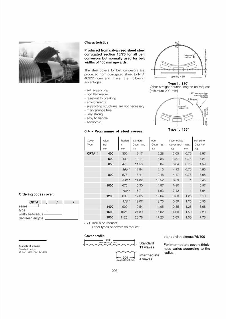
7/27/2019 31801183 Idler Roller
http://slidepdf.com/reader/full/31801183-idler-roller 295/308
293
Characteristics
Produced from galvanised sheet steel
corrugated section 18/76 for all beltconveyors but normally used for beltwidths of 400 mm upwards.
The steel covers for belt conveyors areproduced from corrugated sheet to NFA 46322 norm and have the followingadvantages :
- self supporting- non flammable- resistant to breaking- environmental- supporting structures are not necessary- maintenance free- very strong- easy to handle- economic
6.4 - Programme of steel covers
Cover width Radius standard open intermediate complete
Type belt r Cover 180 ° Cover 135 ° Cover 180 ° Thick. Door 45 °
mm mm Kg Kg Kg mm Kg
CPTA 1 400 350 9.17 6.28 3.05 0.75 3.97
500 400 10.11 6.86 3.37 0.75 4.21
650 475 11.53 8.04 3.84 0.75 4.59 550 * 12.94 9.10 4.32 0.75 4.95
800 575 13.41 9.46 4.47 0.75 5.08
650 * 14.82 10.52 6.59 1 5.45
1000 675 15.30 10.87 6.80 1 5.57
750 * 16.71 11.93 7.42 1 5.94
1200 800 17.65 12.64 9.80 1.25 5.19
875 * 19.07 13.70 10.59 1.25 6.55
1400 900 19.54 14.05 10.85 1.25 6.68
1600 1025 21.89 15.82 14.60 1.50 7.29
1800 1125 23.78 17.23 15.85 1.50 7.78
Cover profile
Example of orderingStandard design:CPTA 1, 650/475, 180 ° /836
( * ) Radius on requestOther types of covers on request
836useable length mm
304useable length mm
standard thickness 75/100
For intermediate covers thick-ness varies according to theradius.
Standard11 waves
intermediate4 waves
Type 1, 180 °Other straight haunch lengths on request(minimum 200 mm)
Type 1, 135 °
Ordering codes cover:
CPTA . , / , / seriestypewidth belt/radius
degrees/ lengths
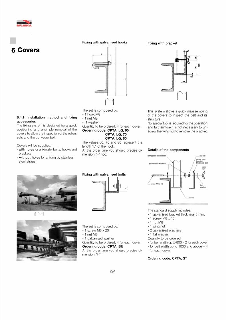
7/27/2019 31801183 Idler Roller
http://slidepdf.com/reader/full/31801183-idler-roller 296/308
Covers6
294
®
6.4.1. Installation method and fixingaccessories
The fixing system is designed for a quick positioning and a simple removal of thecovers to allow the inspection of the rollerssets and the conveyor belt.
Covers will be supplied:- with holes for a fixing by bolts, hooks and
brackets- without holes for a fixing by stainless
steel straps.
Fixing with galvanised hooks
The set is composed by:- 1 hook M8- 1 nut M8- 1 washerQuantity to be ordered: 4 for each coverOrdering code: CPTA, LG, 60
CPTA, LG, 70CPTA, LG, 80
The values 60, 70 and 80 represent thelength “L” of the hook.
At the order time you should precise di-mension “H” too.
Fixing with galvanised bolts
The set is composed by:- 1 screw M8 x 20- 1 nut M8- 1 galvanised washerQuantity to be ordered: 4 for each coverOrdering code: CPTA, BU
At the order time you should precise di-mension “H”.
The standard supply includes:- 1 galvanised bracket thickness 3 mm.
- 1 screw M8 x 40- 1 nut M8- 1 wing nut- 2 galvanised washers- 1 flat washerQuantity to be ordered:- for belt width up to 800 = 2 for each cover- for belt width up to 1000 and above = 4
for each cover
Ordering code: CPTA, ST
Details of the components
Fixing with bracket
This system allows a quick disassemblingof the covers to inspect the belt and itsstructure.No special tool is required for the operationand furthermore it is not necessary to un-screw the wing nut to remove the bracket.
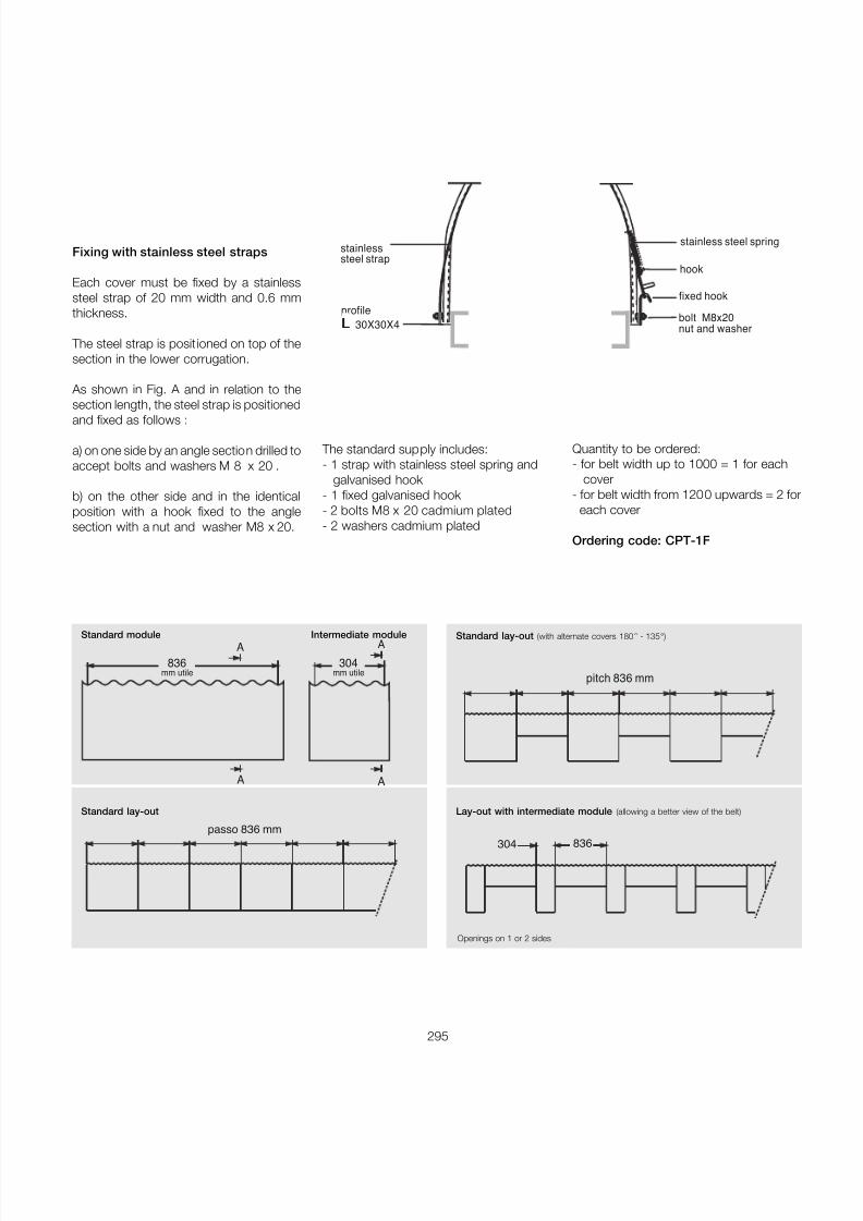
7/27/2019 31801183 Idler Roller
http://slidepdf.com/reader/full/31801183-idler-roller 297/308
295
Fixing with stainless steel straps
Each cover must be fixed by a stainlesssteel strap of 20 mm width and 0.6 mmthickness.
The steel strap is posit ioned on top of thesection in the lower corrugation.
As shown in Fig. A and in relation to thesection length, the steel strap is positioned
and fixed as follows :
a) on one side by an angle section drilled toaccept bolts and washers M 8 x 20 .
b) on the other side and in the identicalposition with a hook fixed to the anglesection with a nut and washer M8 x 20.
The standard supply includes:- 1 strap with stainless steel spring and
galvanised hook - 1 fixed galvanised hook - 2 bolts M8 x 20 cadmium plated- 2 washers cadmium plated
Quantity to be ordered:- for belt width up to 1000 = 1 for each
cover- for belt width from 1200 upwards = 2 for
each cover
Ordering code: CPT-1F
836mm utile
A
A
304mm utile
A
A
Standard module Intermediate module
Standard lay-out
Standard lay-out (with alternate covers 180 ° - 135 ° )
pitch 836 mm
836304
Lay-out with intermediate module (allowing a better view of the belt)
passo 836 mm
Openings on 1 or 2 sides
stainlesssteel strap
stainless steel spring
hook
nut and washerbolt M8x20
fixed hookprofileL 30X30X4
7/27/2019 31801183 Idler Roller
http://slidepdf.com/reader/full/31801183-idler-roller 298/308
®
RULMECA GROUP
On the 3rd July 2003 Rulli RulmecaS.p.A. finalised the acquisition of the“Bulk” Business Units of the InterrollGroup. This was composed of four com-panies specialising in the production ofequipment for belt conveyors in bulkhandling applications.
The 4 companies will immediately takethe name of Rulmeca as follows:
• Rulmeca FAA Gmbh. With premiseslocated in Aschersleben, Germany, theymanufacture motorized pulleys in diame-ters from 216 to 800 mm, and fabricatedpulleys and heavy duty rollers with shaftdiameters up to 90 mm for the brown-coal industry.• Rulmeca España S.L. A companylocated in Barbera del Vallès (Barcelona)and manufacturer of mainly Rulmeca PSVtypes of rollers for the Spanish market.• Rulmeca UK Ltd.A company locatedin Corby, UK, and manufacturer of main-ly Rulmeca PSV types of rollers for GreatBritain.• Rulmeca Thailand Co. Ltd. A compa-ny located in Bangkok, Thailand, who
manufacture mainly Rulmeca PSV typeof rollers for Thai markets and parts ofSouth-East Asia.
Through this acquisition the RulmecaGroup strengthens its international pres-ence (already represented thanks to theproduction units Precismeca-RulmecaGroup in France, Germany and Canadaand Rulmeca de Portugal andVenezuela), especially in some tradition-ally important markets of belt conveyorengineering such as Spain and UnitedKingdom or for medium-term strategic
locations such as the new ThailandCompany.
With the acquisition of Rulmeca FAA andtheir specialised production of motor-ized pulleys, the Rulmeca Group adds,not only a new product to its portfolio,but also a new technology to its skillswhen looking ahead to developing thepotential of future markets.
HEADQUARTERS - ITALY RULLI RULMECA S.P.A.Via A. Toscanini, 1I-24011 Almè (Bergamo)ItalyPhone:+39 035 4300111Fax: +39 035 545523Web: www.rulmeca.itE-mail:[email protected]
EuropeFRANCEPRÉCISMÉCA Equipements de ManutentionRue de La GareF-67700 OtterswillerFrancePhone:+33 3 88 71 58 00Fax: +33 3 88 91 28 01http://[email protected]
GERMANY RULMECA FAA GmbHWilslebener Chaussee 12-14D-06449 AscherslebenTel.: +49 (0) 3473 956-0Fax: +49 (0) 3473 956-210Web: www.rulmeca.comE-mail:[email protected]
PRECISMECA-MONTAN GMBH.P.O. Box 1127D-04112 LeipzigGermanyPhone:+49 341 339 898 - 0Fax: +49 341 9010 549http://www.precismeca.netE-mail:[email protected]
PRECISMECA-MONTAN GMBH.Sales Office Dudweiler Landstrasse 151D-66123 SaarbrückenGermanyPhone:+49 681 91012 0Fax: +49 681 91012 10http://[email protected]
GREAT BRITAINRULMECA UK Ltd.Brunel Road, Earlstrees Ind. EstateGB – Corby, Northants NN17 4UXTel.: +44 1536 200 322Fax: +44 1536 748 505Web: www.rulmeca.comE-mail:[email protected]
PORTUGALRULMECA INTERROLL DE PORTUGALApartado 69 – Centro Cívico6201-909 CovilhaPortugalPhone:+351 75 330780Fax: +351 75 330789E-mail:[email protected]
RUSSIA
RULMECA FAA GmbHBüro Moskau:Leninski Prospekt 95 A117313 MoskauRussiaTel.: +7 095 937 5243Fax: +7 095 132 3774E-mail:[email protected]
SPAINRULMECA ESPAÑA S.L.C.I. Santiga, C/ Puig dels Tudons, 5E-08210 Barberà del Vallès (Barcelona)SpainPhone:+34 93 729 96 52Fax: +34 93 718 96 50Web: www.rulmeca.comE-mail:[email protected]
North & South AmericaCANADA / USA PRECISMECA LIMITED606 – 19th AvenueNisku, Alberta T9E 7W1CanadaPhone:+1 780 955 2733Toll free: 1-800-661-4065Fax: +1 780 955 9412http://[email protected]
VENEZUELA INDUSTRIAS RULMECA S.A.Zona Industrial Municipal NorteCalle Este Oeste Galpón 67-200Valencia, Edo. Carabobo. VenezuelaPhone:+58-241-833.62.49/833.60.97/833.61.12Fax: +58-241-832.15.17http://www.rulmeca.com.veE-mail:[email protected]
AsiaTHAILANDRULMECA Thailand Co. Ltd.41/6 Moo 6, Bangchalong, BangpleeSamutprakarn 10540 ThailandTel.: +66 2 337 0188 91Fax: +66 2 337 01 92Web: www.rulmeca.comE-mail:[email protected]
AGENTS
Europe AUSTRIA RULLI RULMECA S.p.A.Tel.: +39 035 4300111E-mail:[email protected]
BELGIUMRULLI RULMECA S.p.A.Tel.: +39 035 4300111E-mail:[email protected]
CZECH REPUBLIK INTERROLL CZ, s.r.o.Ulica G. Simka c.p. 3147CZ - 69003 BreclavCzech RepublikTel.: +420 627 330 210Fax: +420 627 330 211E-mail:[email protected]
DENMARK / SWEDENINTERROLL NORDICHammerholmen 2-6DK - 2650 HvidovreDenmarkTel.: +45 36 88 33 43Fax: +45 36 88 33 72E-mail:[email protected]
GREECETECOM KOUKOULIS LTD.Ag. Nicolaou 6016674 GlyfadaGreeceTel.: +30-2109604101 , 9604102Fax: +30-2109604100
FINLANDINTERROLL SBU-BULK Markku SarjokoskiFinerintie 20FIN-03250 Ojakkala – FINLANDTel.: +358 922435510Fax: +358 922435100E-mail:[email protected]
296
7/27/2019 31801183 Idler Roller
http://slidepdf.com/reader/full/31801183-idler-roller 299/308
KOSOVOSM KOMERCPristineArta EmshirKosovo
Tel.: +381 38549247Fax: +381 38549248
NORVAY INTERROLL NORWAY Tel.: +47 32 882600Fax: +47 32 882610E-mail:[email protected]
MACEDONIA ROLLERPestani, 9600 OhridMakedonijaTel./Fax:+389 96 285781E-mail:[email protected]
NEDERLANDRULLI RULMECA S.p.A.Tel.: +39 035 4300111E-mail:[email protected]
POLANDINTERROLL POLSKA Sp. Z.o.o.Ul. Jagiellonska 78 pok. 3.3103-301 WarszawaTel.: +48 22 3346343Fax: +48 22 6757292
SLOVENIJA / CR OATIA 3-TEC prehrambena tehnologija-hlajenjein energetika-logistika d.o.o.SI-1000 Ljbljana Dravska ulica 7Tel.: + 386 1 5656370Tel.: +386 1 5656371Fax: +386 1 5656372E-mail:[email protected]
SWITZERLANDRULLI RULMECA SPA Tel.: +39 035 4300111E-mail:[email protected]
TURKEY ROL-ER MAKINA SAN. VE. TIC. LTD. STI.Zihni Sakaryali sok.UFUKApt. No.1 D.11TUR - 81070 Suadiye Istanbul
Phone: +90-216-386 3775Fax: +090-216-386 [email protected]
North & South America ARGENTINA INTERROLL SOUTH AMERICA Calle 117 Nro. 3591AR - B1650NRU San MartinProvincia de Buenos AiresArgentinaTel.: +54 11 4753 8005Fax: +54 11 4754 1332E-mail:[email protected]
CHILESOCIEDAD COMERCIAL POLYBANDAS LIMITADA Santa Lucia # 10813 La FloridaSantiagoRUT: 77.595.750 – 6Tel.: +52 229 92 74 777Fax: +52 229 92 18 119E-mail:[email protected]
Avda. 5 de Abril # 3743 Estación CentralSantiagoRUT: 77.595.750 – 6Tel.: +56 2 778 3468 – 776 1756Fax: +56 2 779 6721E-mail:[email protected]
COSTA RICA ISOTEX DE CENTROAMERICA S.A.Apdo. 6493-1000, San José – Costa RicaCarretera A Heredia, Frente Al CementerioJardines Del Recuerdo, Heredia,Costa RicaTel: +506-262-51-11Fax:+506-260-14-20E-mail: [email protected]
MEXICOEUROPEAN CONSULTING CORP. S.C.Bugambilia N. 7 Desp. 10Fracc. Jardines del VirginiaC.P. 94294 Boca del Rio
Veracruz, Ver. MexicoTel./Fax: +52 229 92 58 000 or +52 229 92 74 777E-mail: [email protected]
AsiaSINGAPOREINTERROLL (ASIA) PTE. LTD.11 Kian Teck Drive628828 SingaporeRepublic of SingaporeTel.: +65 266 6322Fax: +65 266 6849E-mail:[email protected]
BANGLADESHS.A. TRADING COMPANY 1686 Halishahar RoadPathantoolyChittagong 4100BangladeshTel.: +880 - 31 - 623376 (610063 / 723931)Fax: +880 - 31 - 610063 (710957 / 723931)E-mail:[email protected]
CHINA INTERROLL (ASIA) Pte. Ltd.Suzhou Office, Room 6 D6 Floor, Jiancheng MansionNo. 128 Jinjhiu RoadSuzhou Industrial Park215021 SuzhouChinaTel.: +86 512 761 93 95Fax: +86 512 761 93 92E-mail:[email protected]
JAPANINTERROLL (JAPAN) CO. LTD.Tokyo Genbuko Kaikan 10F,5-30-13 Toyo Koto-ku,Tokyo 135-0016,JapanTel.: +81 3 5617 8071Fax: +81 3 5617 80 72
E-mail:[email protected] P.T. Himalaya Everest JayaJl. Daan Mogot Km.10 No. 151, Pesing Poglar,Jakarta 11710, IndonesiaTel.: +62-21 5448966Fax: +62-21-6194658, 6191925E-mail:[email protected]
PAKISTANMUNIR ASSOCIATES124 – A. Main ShadmanLahore – 54000PakistanTel: +92 42 7587890 – 7561498 – 412921Fax: +92 42 7574846 – 7561499E-mail: [email protected]
PHILIPPINESTIGER MACHINERY & INDUSTRIAL CORPORATION359 F. San Diego St., Viente RealesDalandanan, Valenzuela City 1440PhilippinesTel: +63-2-291-2222Fax: +63-2-291-2226
OceaniaNUEVA ZELANDA APPLIED CONVEYOR AND POLYMERS LTD.21 Holmes Rd, Manurewa,Auckland,New ZealandTel. +64-9-2676070Fax: +64-9-2676080
Africa ALGERIA ABDELHAMID HOCINEVilla N° 9 Cité EssaadaMont-PlaisantAnnabaAlgeriaTel.: +213 - 8 - 866838Fax: +213 - 8 - 864580
CAP MED MONTPELLIER29, Rue Balard34000 MontpellierTel./Fax: +33 4 67927961
EGYPTRODANThe Egyptian Center for road and quarry equipment163 Gesr El-Suez Heliopolis,Cairo EgyptTel.: +20 2 2979040Fax: +20 2 2978960E-mail:[email protected]
MAURITANIA M.R.P.S.Rue Médiane BP 631
NouadhibouMauritanieTel.: +222 5 746 017Fax: +222 5 745 476
MAROCCOSNR MOROCCO17, Rue Buzancy BelvédèreCasablanca 20300MarocTel.: +212 22 66 76 80Fax: +212 22 66 51 66E-mail:[email protected]
SOUTH AFRICA INTERROLL S.A. (PTY. Ltd.)P.O. Box 327Isando 1600ZA - GautengSouth AfricaTel.: +27 11 974 19 01Fax: +27 11 974 18 96E-mail:[email protected]
Middle EastJORDANFUAD ABUJABER & SONSFARRADJ & COP.O. Box 974 AmmanJordanTel.: +962-6-4893020 4885980 4885981Fax: +962-6-4891205E-mail:[email protected]
KUWAITUnited Maintenance Equipment CO. W.L.L.P.O. Box: 42387 Shuwaikh (70654)KuwaitTel.: +965 4844835 – 4837069 – 4816598Fax: +965 4837068E-mail:[email protected]
SAUDI ARABIA AZZAM TRADING & CONT. EST.P.O. Box 14542
Jeddah 21491Saudi ArabiaTel.: +966 2 694 0930Fax: +966 2 664 0982
UNITED ARAB EMIRATESDIESEL EQUIPMENT ESTABLISHMENTP.O. BOX 2206 Dubai,United Arab EmiratesTel.: +971 4 2894407Fax:+971 4 2894408
297

7/27/2019 31801183 Idler Roller
http://slidepdf.com/reader/full/31801183-idler-roller 300/308
NOTES

7/27/2019 31801183 Idler Roller
http://slidepdf.com/reader/full/31801183-idler-roller 301/308
NOTES

7/27/2019 31801183 Idler Roller
http://slidepdf.com/reader/full/31801183-idler-roller 302/308
NOTES

7/27/2019 31801183 Idler Roller
http://slidepdf.com/reader/full/31801183-idler-roller 303/308
NOTES

7/27/2019 31801183 Idler Roller
http://slidepdf.com/reader/full/31801183-idler-roller 304/308
NOTES

7/27/2019 31801183 Idler Roller
http://slidepdf.com/reader/full/31801183-idler-roller 305/308
NOTES

7/27/2019 31801183 Idler Roller
http://slidepdf.com/reader/full/31801183-idler-roller 306/308
Co pyright © J uly 2003RULLI RULMECA S.p.A.
7/27/2019 31801183 Idler Roller
http://slidepdf.com/reader/full/31801183-idler-roller 307/308
All dimensions indicated in this catalogue
are subject to working tolerances and,although the drawings are faithfully produ-ced they are not necessarily binding.
Rulli Rulmeca SpA reserves the right tomodify any product without notice.
7/27/2019 31801183 Idler Roller
http://slidepdf.com/reader/full/31801183-idler-roller 308/308