Embed Size (px)
Citation preview

Installation Manual
Pure IP-PBX
Thank you for purchasing this Panasonic product.
Please read this manual carefully before using this product and save this manual for future use.
KX-NS1000: PCMPR Software File Version 001.10000 or later
Model No. KX-NS1000
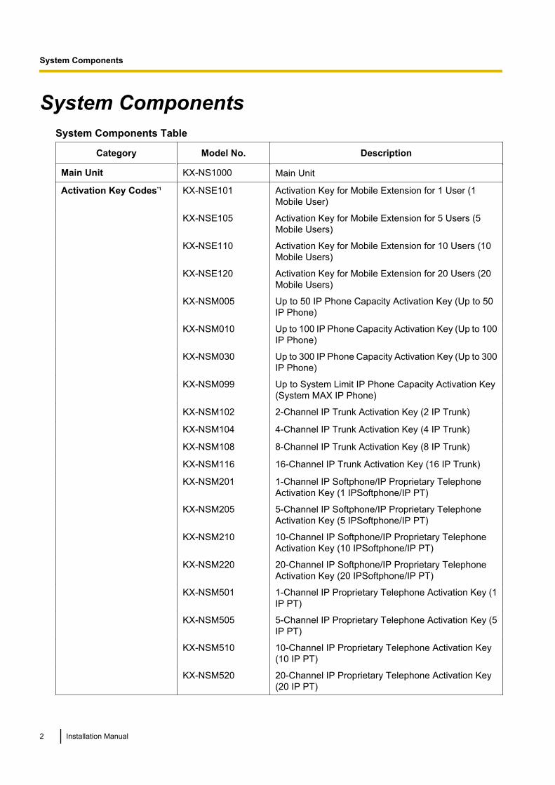
System ComponentsSystem Components Table
Category Model No. Description
Main Unit KX-NS1000 Main Unit
Activation Key Codes*1 KX-NSE101 Activation Key for Mobile Extension for 1 User (1Mobile User)
KX-NSE105 Activation Key for Mobile Extension for 5 Users (5Mobile Users)
KX-NSE110 Activation Key for Mobile Extension for 10 Users (10Mobile Users)
KX-NSE120 Activation Key for Mobile Extension for 20 Users (20Mobile Users)
KX-NSM005 Up to 50 IP Phone Capacity Activation Key (Up to 50IP Phone)
KX-NSM010 Up to 100 IP Phone Capacity Activation Key (Up to 100IP Phone)
KX-NSM030 Up to 300 IP Phone Capacity Activation Key (Up to 300IP Phone)
KX-NSM099 Up to System Limit IP Phone Capacity Activation Key(System MAX IP Phone)
KX-NSM102 2-Channel IP Trunk Activation Key (2 IP Trunk)
KX-NSM104 4-Channel IP Trunk Activation Key (4 IP Trunk)
KX-NSM108 8-Channel IP Trunk Activation Key (8 IP Trunk)
KX-NSM116 16-Channel IP Trunk Activation Key (16 IP Trunk)
KX-NSM201 1-Channel IP Softphone/IP Proprietary TelephoneActivation Key (1 IPSoftphone/IP PT)
KX-NSM205 5-Channel IP Softphone/IP Proprietary TelephoneActivation Key (5 IPSoftphone/IP PT)
KX-NSM210 10-Channel IP Softphone/IP Proprietary TelephoneActivation Key (10 IPSoftphone/IP PT)
KX-NSM220 20-Channel IP Softphone/IP Proprietary TelephoneActivation Key (20 IPSoftphone/IP PT)
KX-NSM501 1-Channel IP Proprietary Telephone Activation Key (1IP PT)
KX-NSM505 5-Channel IP Proprietary Telephone Activation Key (5IP PT)
KX-NSM510 10-Channel IP Proprietary Telephone Activation Key(10 IP PT)
KX-NSM520 20-Channel IP Proprietary Telephone Activation Key(20 IP PT)
2 Installation Manual
System Components
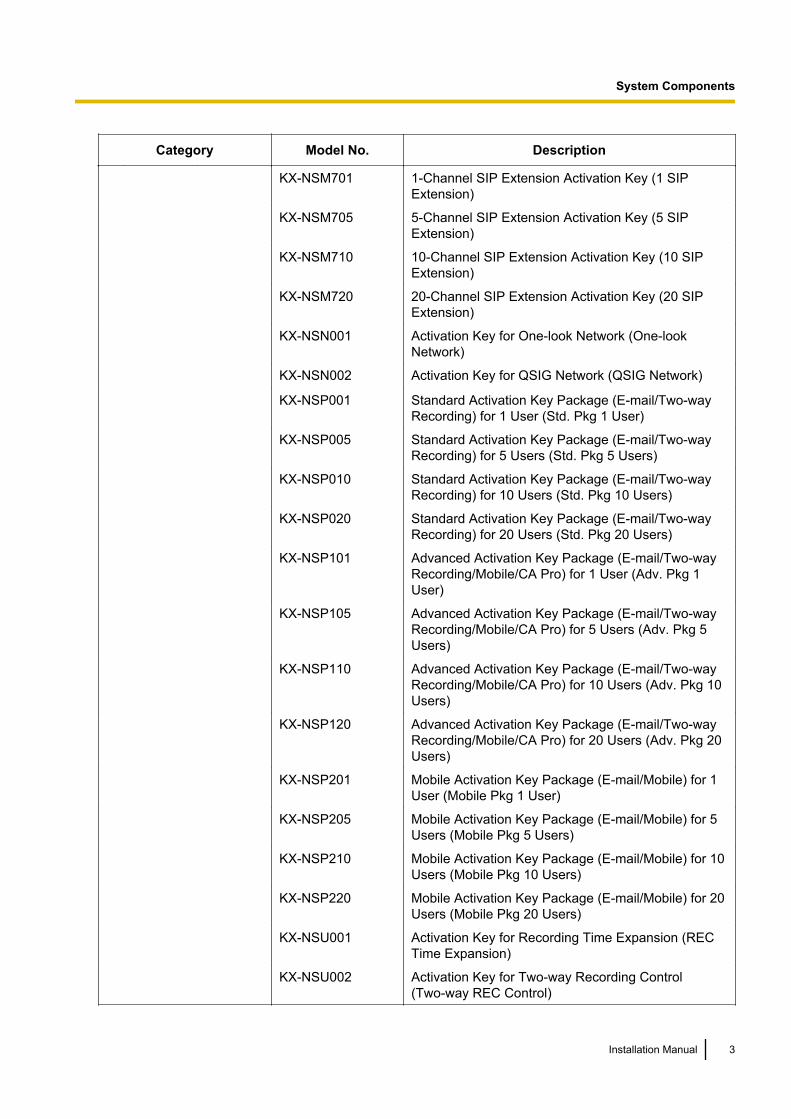
Category Model No. Description
KX-NSM701 1-Channel SIP Extension Activation Key (1 SIPExtension)
KX-NSM705 5-Channel SIP Extension Activation Key (5 SIPExtension)
KX-NSM710 10-Channel SIP Extension Activation Key (10 SIPExtension)
KX-NSM720 20-Channel SIP Extension Activation Key (20 SIPExtension)
KX-NSN001 Activation Key for One-look Network (One-lookNetwork)
KX-NSN002 Activation Key for QSIG Network (QSIG Network)
KX-NSP001 Standard Activation Key Package (E-mail/Two-wayRecording) for 1 User (Std. Pkg 1 User)
KX-NSP005 Standard Activation Key Package (E-mail/Two-wayRecording) for 5 Users (Std. Pkg 5 Users)
KX-NSP010 Standard Activation Key Package (E-mail/Two-wayRecording) for 10 Users (Std. Pkg 10 Users)
KX-NSP020 Standard Activation Key Package (E-mail/Two-wayRecording) for 20 Users (Std. Pkg 20 Users)
KX-NSP101 Advanced Activation Key Package (E-mail/Two-wayRecording/Mobile/CA Pro) for 1 User (Adv. Pkg 1User)
KX-NSP105 Advanced Activation Key Package (E-mail/Two-wayRecording/Mobile/CA Pro) for 5 Users (Adv. Pkg 5Users)
KX-NSP110 Advanced Activation Key Package (E-mail/Two-wayRecording/Mobile/CA Pro) for 10 Users (Adv. Pkg 10Users)
KX-NSP120 Advanced Activation Key Package (E-mail/Two-wayRecording/Mobile/CA Pro) for 20 Users (Adv. Pkg 20Users)
KX-NSP201 Mobile Activation Key Package (E-mail/Mobile) for 1User (Mobile Pkg 1 User)
KX-NSP205 Mobile Activation Key Package (E-mail/Mobile) for 5Users (Mobile Pkg 5 Users)
KX-NSP210 Mobile Activation Key Package (E-mail/Mobile) for 10Users (Mobile Pkg 10 Users)
KX-NSP220 Mobile Activation Key Package (E-mail/Mobile) for 20Users (Mobile Pkg 20 Users)
KX-NSU001 Activation Key for Recording Time Expansion (RECTime Expansion)
KX-NSU002 Activation Key for Two-way Recording Control(Two-way REC Control)
Installation Manual 3
System Components
Category Model No. Description
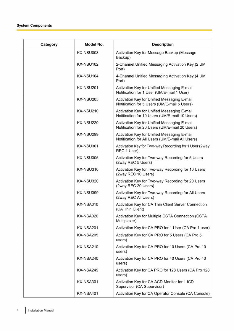
KX-NSU003 Activation Key for Message Backup (MessageBackup)
KX-NSU102 2-Channel Unified Messaging Activation Key (2 UMPort)
KX-NSU104 4-Channel Unified Messaging Activation Key (4 UMPort)
KX-NSU201 Activation Key for Unified Messaging E-mailNotification for 1 User (UM/E-mail 1 User)
KX-NSU205 Activation Key for Unified Messaging E-mailNotification for 5 Users (UM/E-mail 5 Users)
KX-NSU210 Activation Key for Unified Messaging E-mailNotification for 10 Users (UM/E-mail 10 Users)
KX-NSU220 Activation Key for Unified Messaging E-mailNotification for 20 Users (UM/E-mail 20 Users)
KX-NSU299 Activation Key for Unified Messaging E-mailNotification for All Users (UM/E-mail All Users)
KX-NSU301 Activation Key for Two-way Recording for 1 User (2wayREC 1 User)
KX-NSU305 Activation Key for Two-way Recording for 5 Users(2way REC 5 Users)
KX-NSU310 Activation Key for Two-way Recording for 10 Users(2way REC 10 Users)
KX-NSU320 Activation Key for Two-way Recording for 20 Users(2way REC 20 Users)
KX-NSU399 Activation Key for Two-way Recording for All Users(2way REC All Users)
KX-NSA010 Activation Key for CA Thin Client Server Connection(CA Thin Client)
KX-NSA020 Activation Key for Multiple CSTA Connection (CSTAMultiplexer)
KX-NSA201 Activation Key for CA PRO for 1 User (CA Pro 1 user)
KX-NSA205 Activation Key for CA PRO for 5 Users (CA Pro 5users)
KX-NSA210 Activation Key for CA PRO for 10 Users (CA Pro 10users)
KX-NSA240 Activation Key for CA PRO for 40 Users (CA Pro 40users)
KX-NSA249 Activation Key for CA PRO for 128 Users (CA Pro 128users)
KX-NSA301 Activation Key for CA ACD Monitor for 1 ICDSupervisor (CA Supervisor)
KX-NSA401 Activation Key for CA Operator Console (CA Console)
4 Installation Manual
System Components
Category Model No. Description
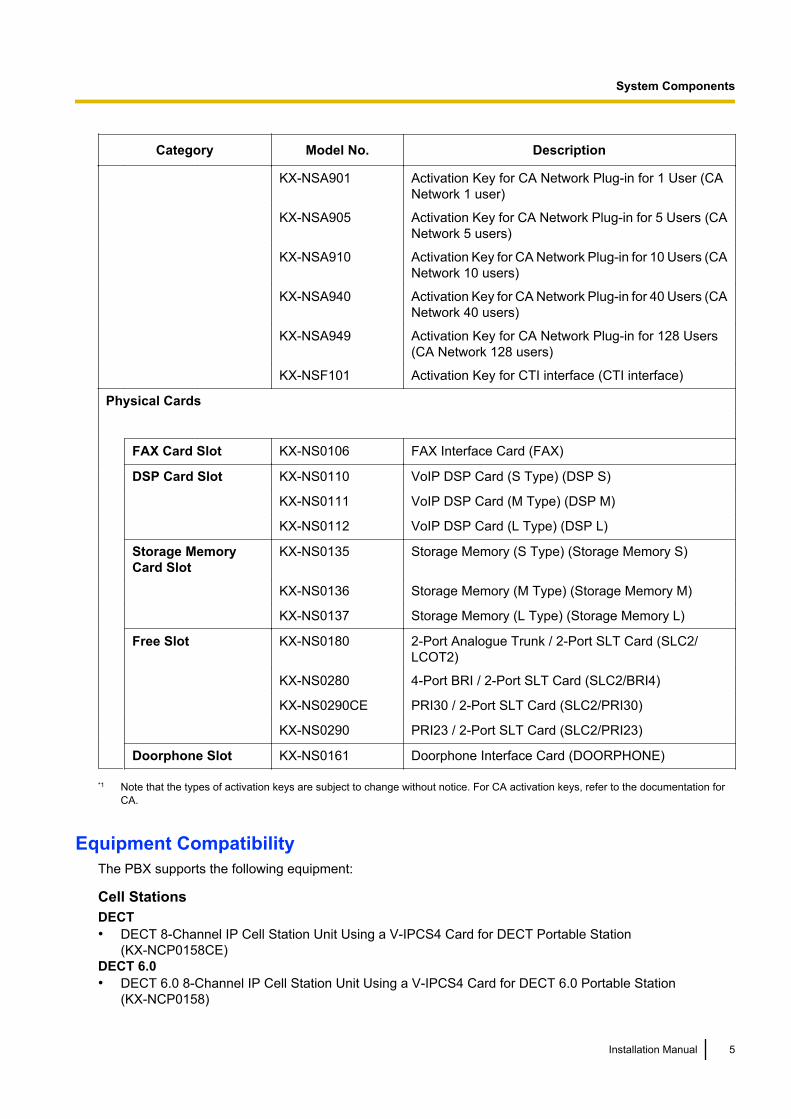
KX-NSA901 Activation Key for CA Network Plug-in for 1 User (CANetwork 1 user)
KX-NSA905 Activation Key for CA Network Plug-in for 5 Users (CANetwork 5 users)
KX-NSA910 Activation Key for CA Network Plug-in for 10 Users (CANetwork 10 users)
KX-NSA940 Activation Key for CA Network Plug-in for 40 Users (CANetwork 40 users)
KX-NSA949 Activation Key for CA Network Plug-in for 128 Users(CA Network 128 users)
KX-NSF101 Activation Key for CTI interface (CTI interface)
Physical Cards
FAX Card Slot KX-NS0106 FAX Interface Card (FAX)
DSP Card Slot KX-NS0110 VoIP DSP Card (S Type) (DSP S)
KX-NS0111 VoIP DSP Card (M Type) (DSP M)
KX-NS0112 VoIP DSP Card (L Type) (DSP L)
Storage MemoryCard Slot
KX-NS0135 Storage Memory (S Type) (Storage Memory S)
KX-NS0136 Storage Memory (M Type) (Storage Memory M)
KX-NS0137 Storage Memory (L Type) (Storage Memory L)
Free Slot KX-NS0180 2-Port Analogue Trunk / 2-Port SLT Card (SLC2/LCOT2)
KX-NS0280 4-Port BRI / 2-Port SLT Card (SLC2/BRI4)
KX-NS0290CE PRI30 / 2-Port SLT Card (SLC2/PRI30)
KX-NS0290 PRI23 / 2-Port SLT Card (SLC2/PRI23)
Doorphone Slot KX-NS0161 Doorphone Interface Card (DOORPHONE)
*1 Note that the types of activation keys are subject to change without notice. For CA activation keys, refer to the documentation forCA.
Equipment CompatibilityThe PBX supports the following equipment:
Cell StationsDECT• DECT 8-Channel IP Cell Station Unit Using a V-IPCS4 Card for DECT Portable Station
(KX-NCP0158CE)DECT 6.0• DECT 6.0 8-Channel IP Cell Station Unit Using a V-IPCS4 Card for DECT 6.0 Portable Station
(KX-NCP0158)
Installation Manual 5
System Components
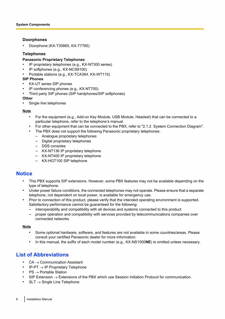
Doorphones• Doorphone (KX-T30865, KX-T7765)
TelephonesPanasonic Proprietary Telephones• IP proprietary telephones (e.g., KX-NT300 series)• IP softphones (e.g., KX-NCS8100)• Portable stations (e.g., KX-TCA364, KX-WT115)SIP Phones• KX-UT series SIP phones• IP conferencing phones (e.g., KX-NT700)• Third party SIP phones (SIP hardphones/SIP softphones)Other• Single line telephones
Note• For the equipment (e.g., Add-on Key Module, USB Module, Headset) that can be connected to a
particular telephone, refer to the telephone’s manual.• For other equipment that can be connected to the PBX, refer to "2.1.2 System Connection Diagram".• The PBX does not support the following Panasonic proprietary telephones:
– Analogue proprietary telephones– Digital proprietary telephones– DSS consoles– KX-NT136 IP proprietary telephone– KX-NT400 IP proprietary telephone– KX-HGT100 SIP telephone
Notice• This PBX supports SIP extensions. However, some PBX features may not be available depending on the
type of telephone.• Under power failure conditions, the connected telephones may not operate. Please ensure that a separate
telephone, not dependent on local power, is available for emergency use.• Prior to connection of this product, please verify that the intended operating environment is supported.
Satisfactory performance cannot be guaranteed for the following:– interoperability and compatibility with all devices and systems connected to this product– proper operation and compatibility with services provided by telecommunications companies over
connected networks
Note• Some optional hardware, software, and features are not available in some countries/areas. Please
consult your certified Panasonic dealer for more information.• In this manual, the suffix of each model number (e.g., KX-NS1000NE) is omitted unless necessary.
List of Abbreviations• CA ® Communication Assistant• IP-PT ® IP Proprietary Telephone• PS ® Portable Station• SIP Extension ® Extensions of the PBX which use Session Initiation Protocol for communication.• SLT ® Single Line Telephone
6 Installation Manual
System Components

IntroductionThis Installation Manual is designed to serve as an overall technical reference for the Panasonic Pure IP-PBX,KX-NS1000. It provides instructions for installing the hardware, and programming the PBX using WebMaintenance Console.
The Structure of this ManualThis manual contains the following sections:Section 1 Safety Precautions
Provides important information intended to prevent personal injury and property damage.Section 2 System Outline
Provides general information on the PBX, including the system capacity and specifications.Section 3 Information about the Activation Keys
Provides information on activation keys, including how to obtain activation keys.Section 4 Installation
Describes the procedures to install the PBX. Detailed instructions for planning the installation site, optionalservice cards, and cabling of peripheral equipment are provided. Further information on system expansionand peripheral equipment installation is included.
Section 5 Programming with Web Maintenance ConsoleDescribes the installation procedure, structure, and functions of the Web Maintenance Console forprogramming IP telephones and the PBX. Further information on programming the PBX for use with SIPtrunks and a VoIP network is included.
Section 6 TroubleshootingProvides information on the PBX and telephone troubleshooting.
Section 7 AppendixProvides information on using the PBX with a VoIP network, the ports used by the PBX, and PBX RegionSuffix Codes and Areas.
About the Other ManualsAlong with this Installation Manual, the following manuals are available:Feature Guide
Describes all basic, optional and programmable features of the PBX.PC Programming Manual
Provides step-by-step instructions for performing system programming using a PC.User Manual
Provides operating instructions for end users using IP-PTs, SIP phones, SLTs, or PSs.
About the software version of your PBXThe contents of this manual apply to PBXs with a certain software version, as indicated on the cover of thismanual. To confirm the software version of your PBX, see "How do I confirm the software version of the PBXor installed cards?" in "2.3 Frequently Asked Questions (FAQ)" of the PC Programming Manual.
Trademarks• The Bluetooth® word mark and logos are owned by the Bluetooth SIG, Inc. and any use of such marks by
Panasonic Corporation is under licence.• Microsoft, Outlook, Internet Explorer, Windows and Windows Vista are either registered trademarks or
trademarks of Microsoft Corporation in the United States and/or other countries.• Mozilla and Firefox are registered trademarks of the Mozilla Foundation.• All other trademarks identified herein are the property of their respective owners.• Microsoft product screen shot(s) reprinted with permission from Microsoft Corporation.
Installation Manual 7
Introduction
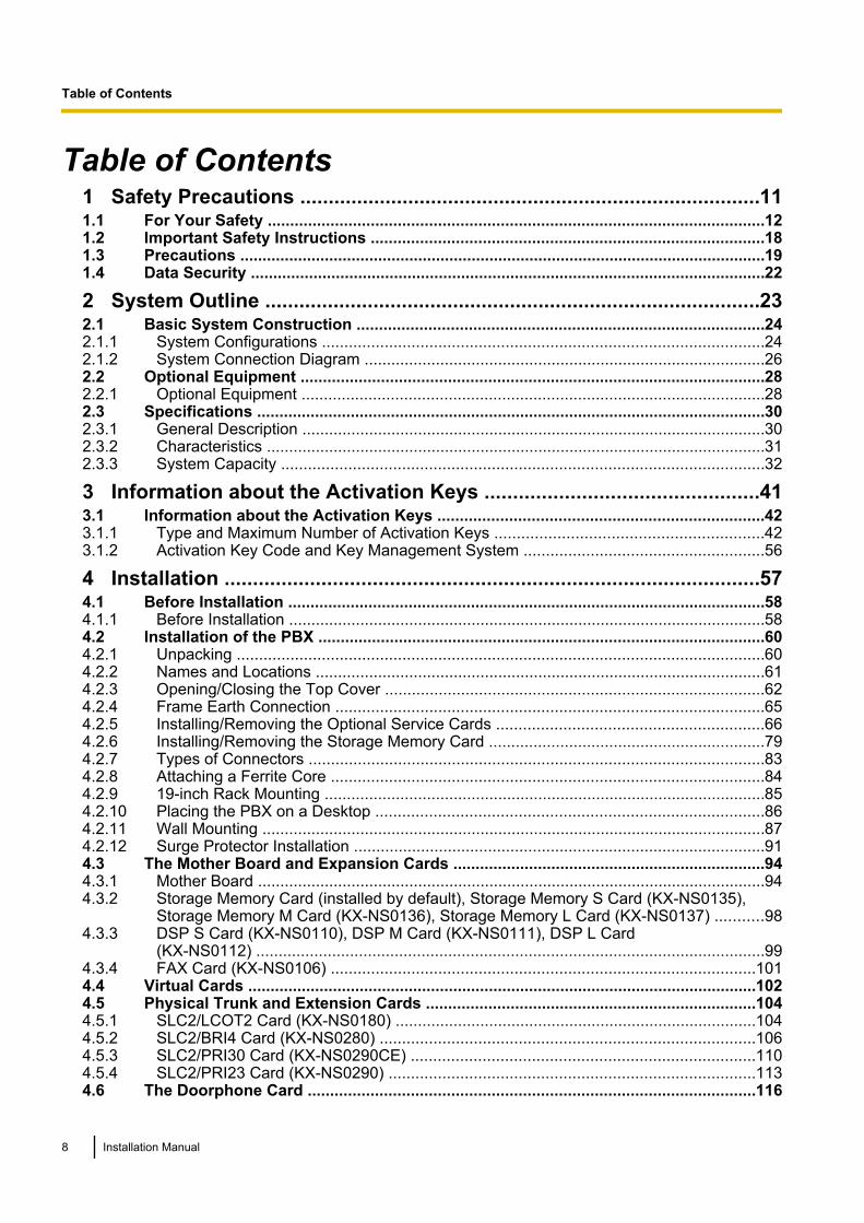
Table of Contents1 Safety Precautions .................................................................................111.1 For Your Safety ...............................................................................................................121.2 Important Safety Instructions ........................................................................................181.3 Precautions ......................................................................................................................191.4 Data Security ...................................................................................................................22
2 System Outline .......................................................................................232.1 Basic System Construction ...........................................................................................242.1.1 System Configurations ...................................................................................................242.1.2 System Connection Diagram ..........................................................................................262.2 Optional Equipment ........................................................................................................282.2.1 Optional Equipment ........................................................................................................282.3 Specifications ..................................................................................................................302.3.1 General Description ........................................................................................................302.3.2 Characteristics ................................................................................................................312.3.3 System Capacity ............................................................................................................32
3 Information about the Activation Keys ................................................413.1 Information about the Activation Keys .........................................................................423.1.1 Type and Maximum Number of Activation Keys ............................................................423.1.2 Activation Key Code and Key Management System ......................................................56
4 Installation ..............................................................................................574.1 Before Installation ...........................................................................................................584.1.1 Before Installation ...........................................................................................................584.2 Installation of the PBX ....................................................................................................604.2.1 Unpacking ......................................................................................................................604.2.2 Names and Locations .....................................................................................................614.2.3 Opening/Closing the Top Cover .....................................................................................624.2.4 Frame Earth Connection ................................................................................................654.2.5 Installing/Removing the Optional Service Cards ............................................................664.2.6 Installing/Removing the Storage Memory Card ..............................................................794.2.7 Types of Connectors ......................................................................................................834.2.8 Attaching a Ferrite Core .................................................................................................844.2.9 19-inch Rack Mounting ...................................................................................................854.2.10 Placing the PBX on a Desktop .......................................................................................864.2.11 Wall Mounting .................................................................................................................874.2.12 Surge Protector Installation ............................................................................................914.3 The Mother Board and Expansion Cards ......................................................................944.3.1 Mother Board ..................................................................................................................944.3.2 Storage Memory Card (installed by default), Storage Memory S Card (KX-NS0135),
Storage Memory M Card (KX-NS0136), Storage Memory L Card (KX-NS0137) ...........984.3.3 DSP S Card (KX-NS0110), DSP M Card (KX-NS0111), DSP L Card
(KX-NS0112) ..................................................................................................................994.3.4 FAX Card (KX-NS0106) ...............................................................................................1014.4 Virtual Cards ..................................................................................................................1024.5 Physical Trunk and Extension Cards ..........................................................................1044.5.1 SLC2/LCOT2 Card (KX-NS0180) .................................................................................1044.5.2 SLC2/BRI4 Card (KX-NS0280) ....................................................................................1064.5.3 SLC2/PRI30 Card (KX-NS0290CE) .............................................................................1104.5.4 SLC2/PRI23 Card (KX-NS0290) ..................................................................................1134.6 The Doorphone Card ....................................................................................................116
8 Installation Manual
Table of Contents
4.6.1 DOORPHONE Card (KX-NS0161) ...............................................................................1164.7 Connection of SLTs ......................................................................................................1184.7.1 Maximum Cabling Distances of the Extension Wiring (Twisted Cable) ........................1184.8 Connecting to a Doorphone, Door Opener, and/or External Sensor .......................1194.9 Connection of Peripherals ...........................................................................................1224.10 LAN Connection ............................................................................................................1274.10.1 LAN Connection for the Main Unit ................................................................................1274.10.2 LAN Connections for IP Telephones ............................................................................1294.11 Power Failure Ports ......................................................................................................1324.12 Starting the PBX ............................................................................................................133
5 Programming with Web Maintenance Console .................................1375.1 Overview of Web Maintenance Console .....................................................................1385.2 PC Connection ..............................................................................................................1395.3 Starting Web Maintenance Console ............................................................................1425.4 Programming the PBX ..................................................................................................1455.4.1 Easy Setup Wizard .......................................................................................................1455.4.2 Enabling the DHCP Server Feature .............................................................................1485.4.3 Installing the Virtual IP Cards to the PBX .....................................................................1495.4.4 Installing Additional Activation Keys .............................................................................1495.4.5 Configuration of the Activation Keys ............................................................................1495.5 Programming a One-look Network ..............................................................................1515.6 Programming a H.323 QSIG Network ..........................................................................1535.6.1 Assigning the Hunt Pattern ...........................................................................................1535.6.2 Programming the Address Translation Table ...............................................................1545.6.3 Programming the Network Settings ..............................................................................1565.7 Programming SIP Trunks .............................................................................................1605.8 Assigning Networking Information to IP Telephones ................................................1625.8.1 Assigning IP Addressing Information ...........................................................................1625.8.2 Setting VLAN Parameters ............................................................................................1805.8.3 Setting Diffserv Parameters .........................................................................................1835.8.4 Configuration of IP Ports ..............................................................................................1865.9 Registering IP Telephones ...........................................................................................1925.9.1 Registering IP Telephones ...........................................................................................1925.9.2 De-registering IP Telephones .......................................................................................1985.10 Configuration of Users .................................................................................................201
6 Troubleshooting ...................................................................................2036.1 Troubleshooting ............................................................................................................2046.1.1 Installation ....................................................................................................................2046.1.2 Connection ...................................................................................................................2066.1.3 Operation ......................................................................................................................2076.1.4 Error Messages ............................................................................................................2096.1.5 Restarting the PBX .......................................................................................................2116.1.6 Troubleshooting by Error Log .......................................................................................213
7 Appendix ...............................................................................................2157.1 Information about Using an IP Network ......................................................................2167.1.1 Using a VoIP Network with the PBX .............................................................................2167.1.2 DHCP (Dynamic Host Configuration Protocol) Server .................................................2197.1.3 VLAN (Virtual LAN) ......................................................................................................2207.1.4 Jitter Buffer ...................................................................................................................2217.1.5 Voice Activity Detection (VAD) .....................................................................................2217.1.6 Network Configuration ..................................................................................................2227.1.7 Network Devices ..........................................................................................................226
Installation Manual 9
Table of Contents
7.1.8 QoS (Quality of Service) ...............................................................................................2277.2 H.323 Trunks ..................................................................................................................2287.2.1 Avoid Multiple IP Networks ...........................................................................................2287.2.2 Gatekeeper ...................................................................................................................2297.2.3 Bandwidth Assessment ................................................................................................2297.2.4 Virtual VoIP Gateway Card Specifications ...................................................................2327.3 SIP Trunks .....................................................................................................................2337.3.1 IP Telephony Service ...................................................................................................2337.3.2 SIP Requirements ........................................................................................................2367.3.3 Router Requirements ...................................................................................................2367.3.4 Bandwidth Requirements .............................................................................................2367.3.5 Virtual SIP Trunk Card Specifications ..........................................................................2387.4 Types of PBX Networks ................................................................................................2397.4.1 One-look Network .........................................................................................................2397.4.2 H.323 QSIG Network ....................................................................................................2437.4.3 Working with Multiple PBX Networks ...........................................................................2447.5 Port Security ..................................................................................................................2457.6 PBX Region Suffix Codes and Areas ..........................................................................2507.7 System Prompt Languages ..........................................................................................252
Index............................................................................................................255
10 Installation Manual
Table of Contents

Section 1
Safety Precautions
This section provides important information intended toprevent personal injury and property damage.
Installation Manual 11
1.1 For Your SafetyTo prevent personal injury and/or damage to property, be sure to observe the following safety precautions.
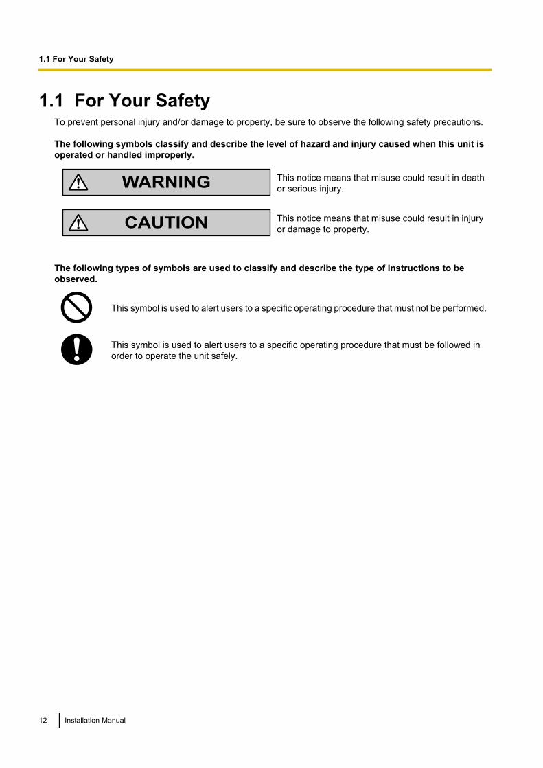
The following symbols classify and describe the level of hazard and injury caused when this unit isoperated or handled improperly.
WARNINGThis notice means that misuse could result in deathor serious injury.
CAUTIONThis notice means that misuse could result in injuryor damage to property.
The following types of symbols are used to classify and describe the type of instructions to beobserved.
This symbol is used to alert users to a specific operating procedure that must not be performed.
This symbol is used to alert users to a specific operating procedure that must be followed inorder to operate the unit safely.
12 Installation Manual
1.1 For Your Safety
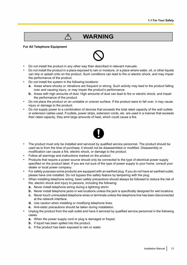
WARNING
For All Telephone Equipment
• Do not install the product in any other way than described in relevant manuals.• Do not install the product in a place exposed to rain or moisture, or a place where water, oil, or other liquids
can drip or splash onto on the product. Such conditions can lead to fire or electric shock, and may impairthe performance of the product.
• Do not install the system in the following locations:a. Areas where shocks or vibrations are frequent or strong. Such activity may lead to the product falling
over and causing injury, or may impair the product’s performance.b. Areas with high amounts of dust. High amounts of dust can lead to fire or electric shock, and impair
the performance of the product.• Do not place the product on an unstable or uneven surface. If the product were to fall over, it may cause
injury or damage to the product.• Do not supply power to a combination of devices that exceeds the total rated capacity of the wall outlets
or extension cables used. If outlets, power strips, extension cords, etc. are used in a manner that exceedstheir rated capacity, they emit large amounts of heat, which could cause a fire.
• The product must only be installed and serviced by qualified service personnel. The product should beused as-is from the time of purchase; it should not be disassembled or modified. Disassembly ormodification can cause a fire, electric shock, or damage to the product.
• Follow all warnings and instructions marked on the product.• Products that require a power source should only be connected to the type of electrical power supply
specified on the product label. If you are not sure of the type of power supply to your home, consult yourdealer or local power company.
• For safety purposes some products are equipped with an earthed plug. If you do not have an earthed outlet,please have one installed. Do not bypass this safety feature by tampering with the plug.
• When installing telephone wiring, basic safety precautions should always be followed to reduce the risk offire, electric shock and injury to persons, including the following:a. Never install telephone wiring during a lightning storm.b. Never install telephone jacks in wet locations unless the jack is specifically designed for wet locations.c. Never touch uninsulated telephone wires or terminals unless the telephone line has been disconnected
at the network interface.d. Use caution when installing or modifying telephone lines.e. Anti-static precautions should be taken during installation.
• Unplug the product from the wall outlet and have it serviced by qualified service personnel in the followingcases:a. When the power supply cord or plug is damaged or frayed.b. If liquid has been spilled into the product.c. If the product has been exposed to rain or water.
Installation Manual 13
1.1 For Your Safety
d. If the product does not operate according to the operating instructions. Adjust only the controls that areexplained in the operating instructions. Improper adjustment of other controls may result in damageand may require service by a qualified technician to restore the product to normal operation.
e. If the product has been dropped or the cabinet has been damaged.f. If product performance deteriorates.
For the PBX
• Do not insert objects of any kind into this product, as they may touch dangerous voltage points or short outparts that could result in a fire or electric shock.
• Do not pull, bend, rest objects on, or chafe the power cord and plug. Damage to the power cord or plugcan cause fire or electric shock.
• Do not attempt to repair the power cord or plug. If the power cord or plug is damaged or frayed, contactan authorised Panasonic Factory Service Centre for a replacement.
• When mounting the PBX on a 19-inch rack, only use the 19-inch rack mounting equipment (attachmentbracket, screws) included with the PBX.
• If damage to the unit exposes any internal parts, disconnect the power supply cord immediately and returnthe unit to your dealer.
• To prevent fires, electric shock, injury, or damage to the product, be sure to follow these guidelines whenperforming any wiring or cabling:a. Before performing any wiring or cabling, unplug the product’s power cord from the outlet. After
completing all wiring and cabling, plug the power cord back into the outlet.b. When laying cables, do not bundle the product’s power cord with the power cords of other devices.c. Do not place any objects on top of the cables connected to the PBX.d. When running cables along the floor, use protectors to prevent the cables from being stepped on.e. Do not run any cables under carpeting.
• Unplug this unit from the AC outlet if it emits smoke, an abnormal smell or makes unusual noise. Theseconditions can cause fire or electric shock. Confirm that smoke has stopped and contact an authorisedPanasonic Factory Service Centre.
• Make sure that the wall that the unit will be attached to is strong enough to support approximately 4 timesthe weight of the unit. If not, it is necessary for the wall to be reinforced.
• When mounting the PBX on a wall, only use the wall-mounting equipment (anchor plugs, screws, metalbrackets) included with the PBX and the wall mounting kit.
• The earthing wire of the AC cable has an effect against external noise and lightning strikes, but it may notbe enough to protect the PBX and to ensure electromagnetic compatibility. A permanent connectionbetween earth and the earth terminal of the PBX must be made.
• Proper earthing (connection to earth) is very important to reduce the risk to the user of electrocution or toprotect the PBX from the bad effects of external noise in the case of a lightning strike. (See "4.2.4 FrameEarth Connection".)
• Plug the power cord firmly into an AC outlet. Otherwise, it can cause fire or electric shock.• Be careful not to drop any components. Dropping components may damage them or cause an injury.• Make sure that the AC outlet is properly earthed, then securely connect the 3-pin AC plug including the
earthed pin.• A lithium battery is used in the mother board. There is a risk of explosion if the battery is replaced with the
incorrect type. Dispose of used batteries according to the manufacturer’s instructions.
14 Installation Manual
1.1 For Your Safety
CAUTION
For All Telephone Equipment
• The product should be kept free of dust, moisture, high temperature (more than 40 °C) and vibration, andshould not be exposed to direct sunlight.
• Unplug the product from the wall outlet before cleaning. Wipe the product with a soft cloth. Do not cleanwith abrasive powders or with chemical agents such as benzene or thinner. Do not use liquid cleaners oraerosol cleaners.
For the PBX
• Do not install the system in the following locations:a. In direct sunlight and hot, cold, or humid places. (Temperature range: 0 °C to 40 °C)b. Areas where sulphuric gases may be present, such as near thermal springs.c. Near devices that generate high frequencies, such as sewing machines or electric welders.
• Do not block the openings of the PBX. Allow space of at least 20 cm above and 10 cm at the sides of thePBX.
• When the PBX is mounted on a 19-inch rack, do not block the openings of the PBX. Allow space of at least10 cm around the PBX’s fan.
• When installing or removing the Storage Memory Card, do not put pressure on any parts of the motherboard. Doing so may result in damage to the PBX.
• When installing or removing the optional service cards, do not put pressure on any parts of the motherboard. Doing so may result in damage to the PBX.
• The Storage Memory Card contains software for all the processes of the PBX and all the customer data.Therefore, do not allow unauthorised access to prevent data leakage.
• Once you have started the PBX, if you unplug the PBX, do not initialise it again as described in "SystemInitialisation Procedure". Otherwise, your programmed data will be cleared. To restart the PBX, refer to"6.1.5 Restarting the PBX".
• Before touching the product (PBX, cards, etc.), discharge static electricity by touching ground or wearingan earthing strap. Failure to do so may cause the PBX to malfunction due to static electricity.
• When relocating the equipment, first disconnect the telecom connection before disconnecting the powerconnection. When the unit is installed in the new location, reconnect the power first, and then reconnectthe telecom connection.
• The power supply cord is used as the main disconnect device. Ensure that the AC outlet is located nearthe equipment and is easily accessible.
• The hook clip poses a choking hazard. Keep the hook clip out of reach of children.• Slots and openings in the front, back and bottom of the cabinet are provided for ventilation; to protect it
from overheating, these openings must not be blocked or covered. The openings should never be blocked
Installation Manual 15
1.1 For Your Safety
by placing the product on a bed, sofa, rug, or other similar surface while in use. The product should neverbe placed near or over a radiator or other heat source. This product should not be placed in a sealedenvironment unless proper ventilation is provided.
• Make sure that the surface behind the PBX is flat and free of obstacles, so that the openings on the backof the PBX will not be blocked.
• Make sure that the surface behind the PBX is not made of wood.• When this product is no longer in use, make sure to detach it from the rack or wall.• Use only the AC power cord included with the PBX.• When the PBX is mounted on a 19-inch rack, make sure that the installation of the unit does not cause the
temperature of the rack to exceed its limit.• Make sure to install all necessary optional service cards in the PBX before performing the wall mounting
procedure. If it is necessary to install or remove a card, make sure to detach the PBX from the wall beforeinstalling or removing the card.
• When driving the screws into the wall, be careful to avoid touching any metal laths, wire laths or plates inthe wall.
• When placing the PBX onto the wall, make sure that the arrows on the metal brackets are pointing upward.If the arrows are not pointing upward, the PBX may fall, resulting in injury.
• When opening the top cover, the power switch must be turned off.• For safety reasons, close the top cover and tighten the screws before operating the PBX.• If the PBX is not installed properly using the securing correct methods, the PBX may fall causing serious
damage.• When the PBX is placed on a desktop, make sure that the PBX is placed as indicated in "4.2.10 Placing
the PBX on a Desktop". Do not place it on its side or upside down.• Performing surge protection is essential. Make sure to follow the instructions in "4.2.12 Surge Protector
Installation".• It is strongly recommended to use SSL encrypted communication when the PC is accessing the PBX via
the Internet. To use SSL encryption, routers must have a port set up for https communication.• To prevent data leakage, render the Storage Memory Card physically unusable before disposal.• Avoid using the same AC outlet for computers and other office equipment, as noise generated by such
equipment may hamper system performance or interrupt the system.• Unplug the system from its power source when wiring, and plug the system back in only after all wiring is
completed.• Trunks should be installed with surge protectors. For details, refer to "4.2.12 Surge Protector
Installation".• When installing or removing the Storage Memory Card, the power switch must be turned off.• When installing or removing the optional service cards, the power switch must be turned off.• For earthing wire, green-and-yellow insulation is required, and the cross-sectional area of the conductor
must be more than 0.75 mm2 or 18 AWG.• When connecting a SLC2/BRI4, SLC2/PRI30 or SLC2/PRI23 card to the trunk, connect through an NT1;
do not connect to the U interface of the trunk directly.• PRI ports of SLC2/PRI30 and SLC2/PRI23 cards are SELV ports and should only be connected to SELV
services.• The MOH port and Pager port are SELV ports and should only be connected to approved SELV devices,
or in Australia, via a Line Isolation Unit with a Telecommunications Compliance Label.• To protect the system, keep the following in mind:
a. Make sure that both connector cases (frame ground) of the RS-232C cross cable (shielded cable) areconductive. If they are not conductive, make sure that both connector cases of the cable are firmlyconnected.
b. If this is not possible, connect the frame of the PBX to the frame of the PC/Printer using an earthingwire in order to prevent difference in the electrical potentials.
16 Installation Manual
1.1 For Your Safety
NoticeFor All Telephone Equipment• Read and understand all instructions.
For the PBX• Keep the unit away from heating appliances and devices that generate electrical noise such as
fluorescent lamps, motors and televisions. These noise sources can interfere with the performance ofthe PBX.
• If you are having problems making calls to outside destinations, follow this procedure to test the trunks:a. Disconnect the PBX from all trunks.b. Connect known working SLTs to those trunks.c. Make a call to an external destination using those SLTs.If a call cannot be carried out correctly, there may be a problem with the trunk that the SLT is connectedto. Contact your telephone company.If all SLTs operate properly, there may be a problem with your PBX. Do not reconnect the PBX to thetrunks until it has been serviced by an authorised Panasonic Factory Service Centre.
Installation Manual 17
1.1 For Your Safety
1.2 Important Safety InstructionsWhen using your telephone equipment, basic safety precautions should always be followed to reduce the riskof fire, electric shock and injury to persons, including the following:• Do not use the product near water, for example, near a bathtub, wash bowl, kitchen sink, or laundry tub,
in a wet basement, or near a swimming pool.• Avoid using wired telephones during an electrical storm. There is a remote risk of electric shock from
lightning.• Do not use a telephone in the vicinity of a gas leak to report the leak.• Rack Mount Instructions—The following or similar rack-mount instructions are included with the installation
instructions:a. Elevated Operating Ambient—If installed in a closed or multi-unit rack assembly, the operating ambient
temperature of the rack environment may be greater than room ambient. Therefore, considerationshould be given to installing the equipment in an environment compatible with the maximum ambienttemperature (Tma) specified by the manufacturer.
b. Reliable Earthing—Reliable earthing of rack-mounted equipment should be maintained. Particularattention should be given to supply connections other than direct connections to the branch circuit (e.g.,use of power strips).
SAVE THESE INSTRUCTIONS
18 Installation Manual
1.2 Important Safety Instructions
1.3 PrecautionsFor users in the United KingdomFOR YOUR SAFETY, PLEASE READ THE FOLLOWING TEXT CAREFULLY.
This appliance is supplied with a moulded three-pin mains plug for your safety and convenience. Should thefuse need to be replaced, please ensure that the replacement fuse is of the same rating and that it is approvedby ASTA or BSI to BS1362.
Check for the ASTA mark or the BSI mark on the body of the fuse.
If the plug contains a removable fuse cover, you must ensure that it is refitted when the fuse is replaced. If youlose the fuse cover, the plug must not be used until a replacement cover is obtained. A replacement fuse covercan be purchased from your local Panasonic dealer.
IF THE FITTED MOULDED PLUG IS UNSUITABLE FOR THE AC OUTLET IN YOUR PREMISES, THEN THEFUSE SHOULD BE REMOVED AND THE PLUG CUT OFF AND DISPOSED OF SAFELY. THERE IS ADANGER OF SEVERE ELECTRICAL SHOCK IF THE CUT-OFF PLUG IS INSERTED INTO ANY 13 AMPSOCKET.
If a new plug is to be fitted, please observe the wiring code as shown below. If in any doubt, please consult aqualified electrician.
WARNINGThis appliance must be earthed.
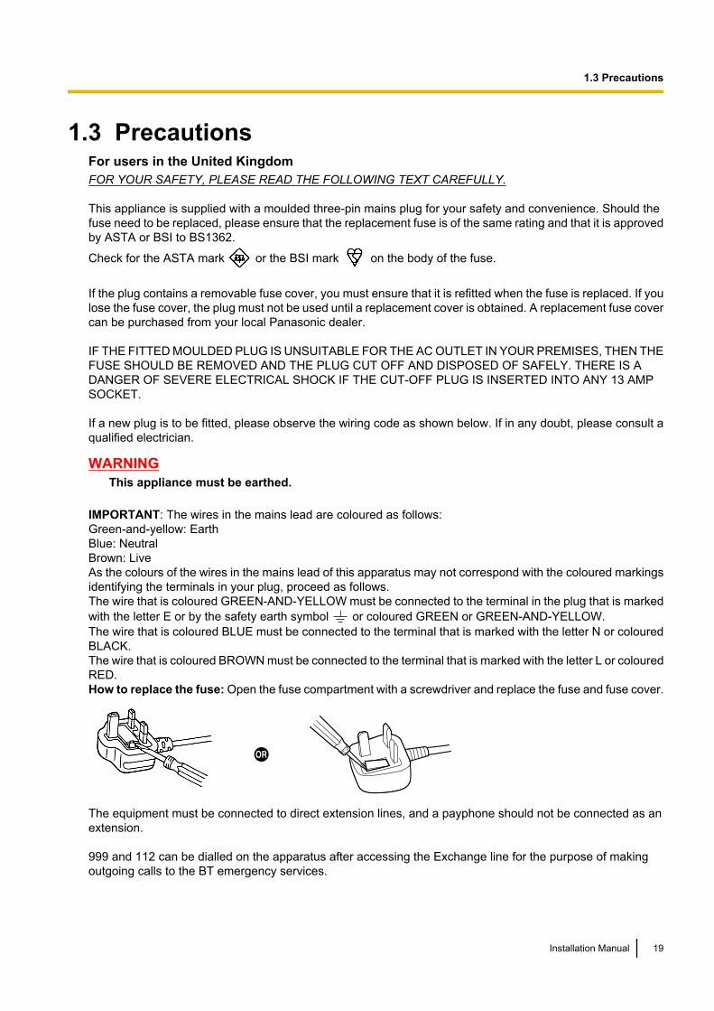
IMPORTANT: The wires in the mains lead are coloured as follows:Green-and-yellow: EarthBlue: NeutralBrown: LiveAs the colours of the wires in the mains lead of this apparatus may not correspond with the coloured markingsidentifying the terminals in your plug, proceed as follows.The wire that is coloured GREEN-AND-YELLOW must be connected to the terminal in the plug that is markedwith the letter E or by the safety earth symbol or coloured GREEN or GREEN-AND-YELLOW.The wire that is coloured BLUE must be connected to the terminal that is marked with the letter N or colouredBLACK.The wire that is coloured BROWN must be connected to the terminal that is marked with the letter L or colouredRED.How to replace the fuse: Open the fuse compartment with a screwdriver and replace the fuse and fuse cover.
The equipment must be connected to direct extension lines, and a payphone should not be connected as anextension.
999 and 112 can be dialled on the apparatus after accessing the Exchange line for the purpose of makingoutgoing calls to the BT emergency services.
Installation Manual 19
1.3 Precautions
During dialling, this apparatus may tinkle the bells of other telephones using the same line. This is not a faultand we advise you not to call the Fault Repair Service.
For users in the European Union only
Information for Users on Collection and Disposal of Old Equipment and used Batteries
These symbols on the products, packaging, and/or accompanying documents mean thatused electrical and electronic products and batteries should not be mixed with generalhousehold waste.For proper treatment, recovery and recycling of old products and used batteries, please takethem to applicable collection points, in accordance with your national legislation and theDirectives 2002/96/EC and 2006/66/EC.By disposing of these products and batteries correctly, you will help to save valuableresources and prevent any potential negative effects on human health and the environmentwhich could otherwise arise from inappropriate waste handling.For more information about collection and recycling of old products and batteries, pleasecontact your local municipality, your waste disposal service or the point of sale where youpurchased the items.Penalties may be applicable for incorrect disposal of this waste, in accordance with nationallegislation.
For business users in the European UnionIf you wish to discard electrical and electronic equipment, please contact your dealer orsupplier for further information.
Information on Disposal in other Countries outside the European UnionThese symbols are only valid in the European Union. If you wish to discard these items,please contact your local authorities or dealer and ask for the correct method of disposal.
Note for the battery symbol (bottom two symbol examples):This symbol might be used in combination with a chemical symbol. In this case it complieswith the requirement set by the Directive for the chemical involved.
For users in Germany only• Machine Noise Information Ordinance, 3rd GPSGV: The highest sound pressure level is 70 dB (A) or less
according to EN ISO 7779.• This equipment is not for use at video display work stations according to BildscharbV.
For users in Finland, Norway and Sweden only• This equipment is intended for installation in restricted access locations where only authorised personnel
may gain access through the use of a special tool, lock and key or other means of security.
For users in New Zealand only• This equipment shall not be set to make automatic calls to the Telecom ‘111’ Emergency Service.• The grant of a Telepermit for any item of terminal equipment indicates only that Telecom has accepted
that the item complies with minimum conditions for connection to its network. It indicates no endorsementof the product by Telecom, nor does it provide any sort of warranty. Above all, it provides no assurance
20 Installation Manual
1.3 Precautions
that any item will work correctly in all respects with another item of Telepermitted equipment of a differentmake or model, nor does it imply that any product is compatible with all of Telecom’s network services.
• This equipment is not capable, under all operating conditions, of correct operation at the higher speeds forwhich it is designed. Telecom will accept no responsibility should difficulties arise in such circumstances.
• Some parameters required for compliance with Telecom’s Telepermit requirements are dependent on theequipment (PBX) associated with this modem. In order to operate within the limits for compliance withTelecom’s Specifications, the associated PBX equipment shall be set to ensure that modem calls areanswered between 3 and 30 seconds of receipt of ringing.
• Using the toll services of a company other than Telecom:If the PBX is set up to use the toll services of a company other than Telecom, the telephone numbersdialled from the Caller Display listings within the PBX will be directed through the toll services of the othercompany because the telephone numbers include the toll access digit and area code digit. A toll chargemay be incurred. Please check with the toll carrier concerned.
• APPLICABLE ONLY TO TELECOM CUSTOMERS WHO HAVE AUTOMATIC ACCESS TO OTHERCARRIERS FOR TOLL CALLSWhen calling back a number from the Caller ID list, all numbers prefixed with "0 + AREA CODE" will beautomatically forwarded to your toll carrier. This includes numbers in your local calling area. The zero +area code should either be removed when calling back local numbers, or check with your toll carrier thata charge will not be levied.
• All persons using this device for recording telephone conversations shall comply with New Zealand law.This requires that at least one party to the conversation is to be aware that it is being recorded. In addition,the principles enumerated in the Privacy Act 1993 shall be complied with in respect to the nature of thepersonal information collected, the purpose for its collection, how it is used, and what is disclosed to anyother party.
• The SLT ports are not specifically designed for 3-wire-connected equipment. 3-wire-connected equipmentmight not respond to incoming ringing when attached to these ports.
For users in Australia only• No External TRC Terminal is provided due to an Internal Link between PE and TRC.
For users in Taiwan only• Lithium batteries can be found in the circuit boards of the mother board and optional service cards of the
PBX.
NoticeRegarding removing or replacing a battery in the circuit board, consult your dealer.
Note• When disposing of any of the above products, all batteries must be removed. Follow the applicable
laws, regulations, and guidelines in your country/area regarding disposal of batteries.• When replacing a battery, use only the same battery type, or an equivalent recommended by the battery
manufacturer.
Installation Manual 21
1.3 Precautions
1.4 Data SecurityIn order to use the PBX safely and correctly, the Security Requirements below must be observed. Failure todo so may result in:• Loss, leakage, falsification or theft of user information.• Illegal use of the PBX by a third party.• Interference or suspension of service caused by a third party.
What is User Information?User Information is defined as:1. Information stored on the Storage Memory Card:
System data, error data and activation key files.2. Information sent from the PBX to a PC or a USB memory device:
System data, sound files for MOH (Music on Hold) and OGM (Outgoing Messages), and activation keyfiles.
Requirements1. The Storage Memory Card contains software for all the processes of the PBX and all the customer data.
Therefore, do not allow unauthorised access to prevent data leakage.2. Always make backups of data stored on the Storage Memory Card and/or perform regular system data
backups to a USB memory device.For details about making backups of data stored on the Storage Memory Card, refer to "7.2.2 Utility—File—File Transfer PBX to PC" in the PC Programming Manual.For details about backing up the system data to a USB memory device, refer to "6.1 Tool—System DataBackup to USB" in the PC Programming Manual.
3. To prevent illegal access from the Internet, activate a Firewall.4. To avoid unauthorised access and possible abuse of the PBX, we strongly recommend:
a. Keeping the password secret.b. Selecting a complex, random password that cannot be easily guessed.c. Changing your password regularly.
5. Perform the following when sending the PBX for repair or handing it over to a third party.a. Make a backup of data stored on the Storage Memory Card.b. Using a formatter, format the Storage Memory Card so that information cannot be retrieved from it.
6. To prevent data leakage, render the Storage Memory Card physically unusable before disposal.7. When user information is sent from the PBX to a PC or a USB memory device, the confidentiality of that
information becomes the responsibility of the customer. Before disposing of the PC or the USB memorydevice, ensure that data cannot be retrieved from it by formatting the hard disk and/or rendering it physicallyunusable.
22 Installation Manual
1.4 Data Security
Section 2
System Outline
This section provides general information on the PBX,including the system capacity and specifications.
Installation Manual 23
2.1 Basic System Construction
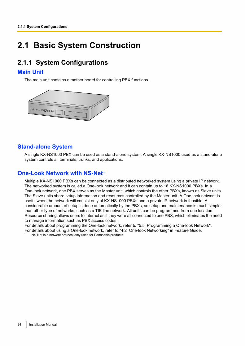
2.1.1 System ConfigurationsMain Unit
The main unit contains a mother board for controlling PBX functions.
Stand-alone SystemA single KX-NS1000 PBX can be used as a stand-alone system. A single KX-NS1000 used as a stand-alonesystem controls all terminals, trunks, and applications.
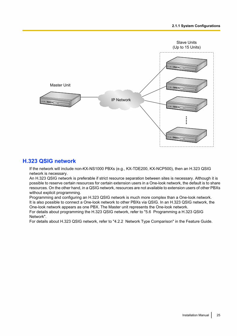
One-Look Network with NS-Net*1
Multiple KX-NS1000 PBXs can be connected as a distributed networked system using a private IP network.The networked system is called a One-look network and it can contain up to 16 KX-NS1000 PBXs. In aOne-look network, one PBX serves as the Master unit, which controls the other PBXs, known as Slave units.The Slave units share setup information and resources controlled by the Master unit. A One-look network isuseful when the network will consist only of KX-NS1000 PBXs and a private IP network is feasible. Aconsiderable amount of setup is done automatically by the PBXs, so setup and maintenance is much simplerthan other type of networks, such as a TIE line network. All units can be programmed from one location.Resource sharing allows users to interact as if they were all connected to one PBX, which eliminates the needto manage information such as PBX access codes.For details about programming the One-look network, refer to "5.5 Programming a One-look Network".For details about using a One-look network, refer to "4.2 One-look Networking" in Feature Guide.*1 NS-Net is a network protocol only used for Panasonic products.
24 Installation Manual
2.1.1 System Configurations
IP Network
Master Unit
Slave Units
(Up to 15 Units).....
H.323 QSIG networkIf the network will include non-KX-NS1000 PBXs (e.g., KX-TDE200, KX-NCP500), then an H.323 QSIGnetwork is necessary.An H.323 QSIG network is preferable if strict resource separation between sites is necessary. Although it ispossible to reserve certain resources for certain extension users in a One-look network, the default is to shareresources. On the other hand, in a QSIG network, resources are not available to extension users of other PBXswithout explicit programming.Programming and configuring an H.323 QSIG network is much more complex than a One-look network.It is also possible to connect a One-look network to other PBXs via QSIG. In an H.323 QSIG network, theOne-look network appears as one PBX. The Master unit represents the One-look network.For details about programming the H.323 QSIG network, refer to "5.6 Programming a H.323 QSIGNetwork".For details about H.323 QSIG network, refer to "4.2.2 Network Type Comparison" in the Feature Guide.
Installation Manual 25
2.1.1 System Configurations
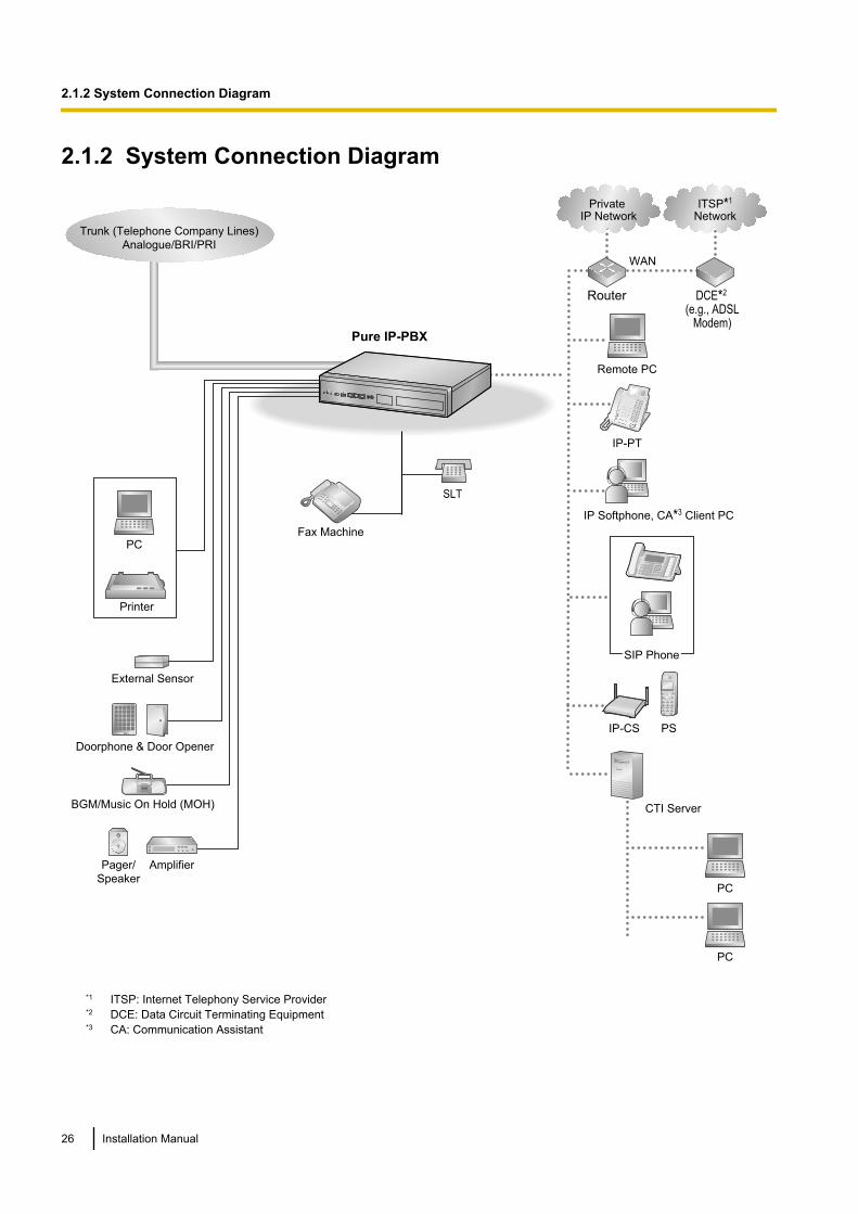
2.1.2 System Connection Diagram
Doorphone & Door Opener
BGM/Music On Hold (MOH)
Pager/
Speaker
PC
Printer
Router
Trunk (Telephone Company Lines)
Analogue/BRI/PRI
Pure IP-PBX
Remote PC
Fax Machine
Amplifier
SLT
External Sensor
IP-PT
IP Softphone, CA*3 Client PC
PC
PC
CTI Server
Private IP Network
ITSP*1
Network
DCE*2
(e.g., ADSL Modem)
WAN
IP-CS PS
SIP Phone
*1 ITSP: Internet Telephony Service Provider*2 DCE: Data Circuit Terminating Equipment*3 CA: Communication Assistant
26 Installation Manual
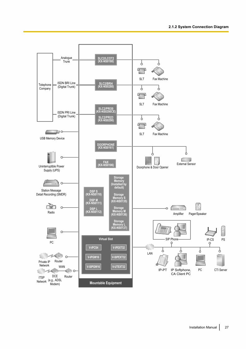
2.1.2 System Connection Diagram
SLT Fax Machine
SLT Fax Machine
SLT Fax Machine
DSP S(KX-NS0110)
DSP M(KX-NS0111)
DSP L(KX-NS0112)
V-IPGW16
V-IPEXT32
V-SIPGW16
V-SIPEXT32
V-IPCS4
V-UTEXT32
FAX(KX-NS0106)
Storage
Memory
(Installed by
default)
Storage
Memory S
(KX-NS0135)
Storage
Memory M
(KX-NS0136)
Storage
Memory L
(KX-NS0137)
Doorphone & Door Opener
Mountable Equipment
External Sensor
Telephone Company
Analogue Trunk
ISDN BRI Line (Digital Trunk)
ISDN PRI Line (Digital Trunk)
PC
Router
Amplifier Pager/Speaker
PCIP Softphone,
CA Client PC
LAN
CTI ServerIP-PT
IP-CS
Private IP Network
ITSP
Network
DCE
(e.g., ADSL
Modem)
WAN
Router
PS
DOORPHONE(KX-NS0161)
SLC2/LCOT2(KX-NS0180)
SLC2/BRI4(KX-NS0280)
SLC2/PRI30(KX-NS0290CE)
SLC2/PRI23(KX-NS0290)
Radio
Station Message
Detail Recording (SMDR)
SIP Phone
Uninterruptible Power
Supply (UPS)
Virtual Slot
USB Memory Device
Installation Manual 27
2.1.2 System Connection Diagram
2.2 Optional Equipment
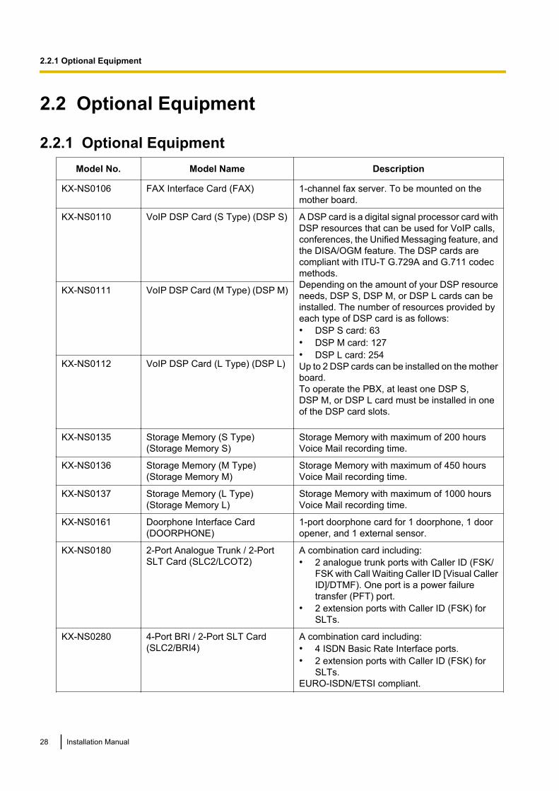
2.2.1 Optional EquipmentModel No. Model Name Description
KX-NS0106 FAX Interface Card (FAX) 1-channel fax server. To be mounted on themother board.
KX-NS0110 VoIP DSP Card (S Type) (DSP S) A DSP card is a digital signal processor card withDSP resources that can be used for VoIP calls,conferences, the Unified Messaging feature, andthe DISA/OGM feature. The DSP cards arecompliant with ITU-T G.729A and G.711 codecmethods.Depending on the amount of your DSP resourceneeds, DSP S, DSP M, or DSP L cards can beinstalled. The number of resources provided byeach type of DSP card is as follows:• DSP S card: 63• DSP M card: 127• DSP L card: 254Up to 2 DSP cards can be installed on the motherboard.To operate the PBX, at least one DSP S,DSP M, or DSP L card must be installed in oneof the DSP card slots.
KX-NS0111 VoIP DSP Card (M Type) (DSP M)
KX-NS0112 VoIP DSP Card (L Type) (DSP L)
KX-NS0135 Storage Memory (S Type)(Storage Memory S)
Storage Memory with maximum of 200 hoursVoice Mail recording time.
KX-NS0136 Storage Memory (M Type)(Storage Memory M)
Storage Memory with maximum of 450 hoursVoice Mail recording time.
KX-NS0137 Storage Memory (L Type)(Storage Memory L)
Storage Memory with maximum of 1000 hoursVoice Mail recording time.
KX-NS0161 Doorphone Interface Card(DOORPHONE)
1-port doorphone card for 1 doorphone, 1 dooropener, and 1 external sensor.
KX-NS0180 2-Port Analogue Trunk / 2-PortSLT Card (SLC2/LCOT2)
A combination card including:• 2 analogue trunk ports with Caller ID (FSK/
FSK with Call Waiting Caller ID [Visual CallerID]/DTMF). One port is a power failuretransfer (PFT) port.
• 2 extension ports with Caller ID (FSK) forSLTs.
KX-NS0280 4-Port BRI / 2-Port SLT Card(SLC2/BRI4)
A combination card including:• 4 ISDN Basic Rate Interface ports.• 2 extension ports with Caller ID (FSK) for
SLTs.EURO-ISDN/ETSI compliant.
28 Installation Manual
2.2.1 Optional Equipment
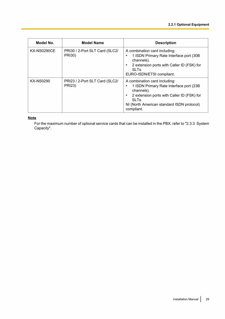
Model No. Model Name Description
KX-NS0290CE PRI30 / 2-Port SLT Card (SLC2/PRI30)
A combination card including:• 1 ISDN Primary Rate Interface port (30B
channels).• 2 extension ports with Caller ID (FSK) for
SLTs.EURO-ISDN/ETSI compliant.
KX-NS0290 PRI23 / 2-Port SLT Card (SLC2/PRI23)
A combination card including:• 1 ISDN Primary Rate Interface port (23B
channels).• 2 extension ports with Caller ID (FSK) for
SLTs.NI (North American standard ISDN protocol)compliant.
NoteFor the maximum number of optional service cards that can be installed in the PBX, refer to "2.3.3 SystemCapacity".
Installation Manual 29
2.2.1 Optional Equipment
2.3 Specifications
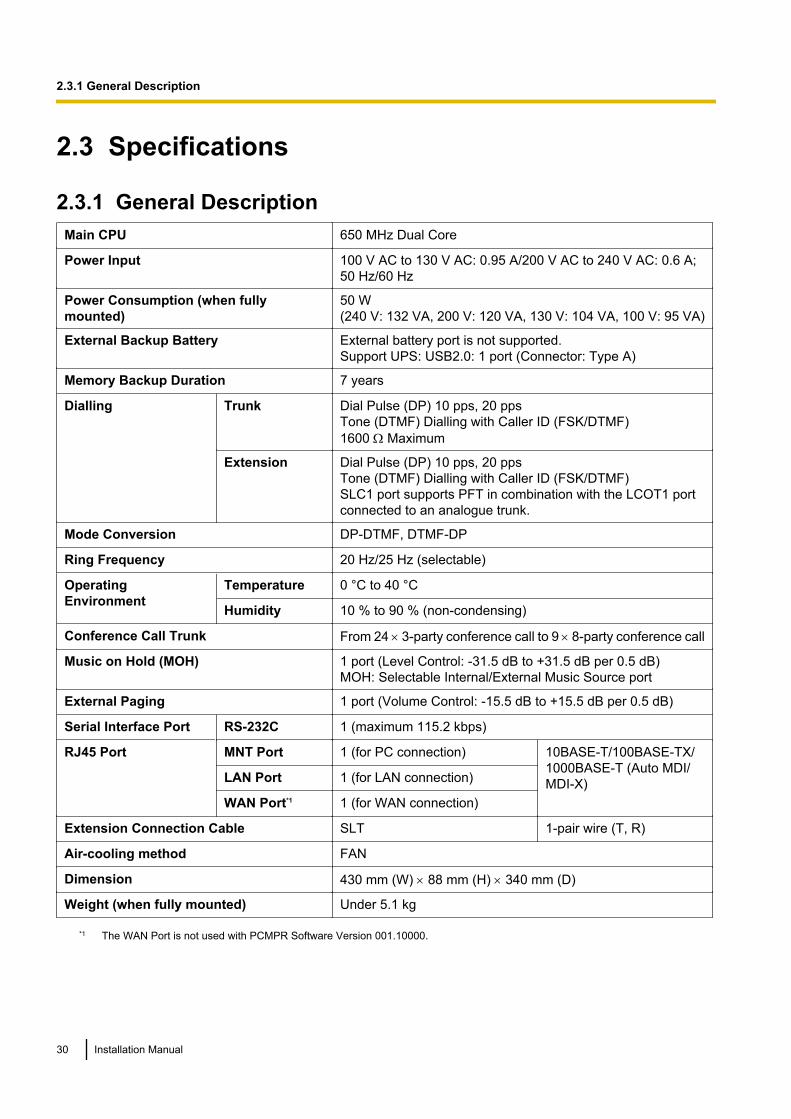
2.3.1 General DescriptionMain CPU 650 MHz Dual Core
Power Input 100 V AC to 130 V AC: 0.95 A/200 V AC to 240 V AC: 0.6 A;50 Hz/60 Hz
Power Consumption (when fullymounted)
50 W(240 V: 132 VA, 200 V: 120 VA, 130 V: 104 VA, 100 V: 95 VA)
External Backup Battery External battery port is not supported.Support UPS: USB2.0: 1 port (Connector: Type A)
Memory Backup Duration 7 years
Dialling Trunk Dial Pulse (DP) 10 pps, 20 ppsTone (DTMF) Dialling with Caller ID (FSK/DTMF)1600 W Maximum
Extension Dial Pulse (DP) 10 pps, 20 ppsTone (DTMF) Dialling with Caller ID (FSK/DTMF)SLC1 port supports PFT in combination with the LCOT1 portconnected to an analogue trunk.
Mode Conversion DP-DTMF, DTMF-DP
Ring Frequency 20 Hz/25 Hz (selectable)
OperatingEnvironment
Temperature 0 °C to 40 °C
Humidity 10 % to 90 % (non-condensing)
Conference Call Trunk From 24 ́ 3-party conference call to 9 ́ 8-party conference call
Music on Hold (MOH) 1 port (Level Control: -31.5 dB to +31.5 dB per 0.5 dB)MOH: Selectable Internal/External Music Source port
External Paging 1 port (Volume Control: -15.5 dB to +15.5 dB per 0.5 dB)
Serial Interface Port RS-232C 1 (maximum 115.2 kbps)
RJ45 Port MNT Port 1 (for PC connection) 10BASE-T/100BASE-TX/1000BASE-T (Auto MDI/MDI-X)LAN Port 1 (for LAN connection)
WAN Port*1 1 (for WAN connection)
Extension Connection Cable SLT 1-pair wire (T, R)
Air-cooling method FAN
Dimension 430 mm (W) ´ 88 mm (H) ´ 340 mm (D)
Weight (when fully mounted) Under 5.1 kg
*1 The WAN Port is not used with PCMPR Software Version 001.10000.
30 Installation Manual
2.3.1 General Description
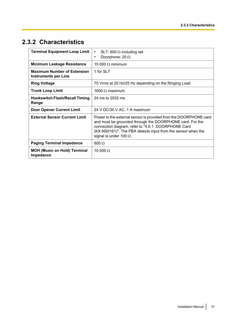
2.3.2 CharacteristicsTerminal Equipment Loop Limit • SLT: 600 W including set
• Doorphone: 20 W
Minimum Leakage Resistance 15 000 W minimum
Maximum Number of ExtensionInstruments per Line
1 for SLT
Ring Voltage 75 Vrms at 20 Hz/25 Hz depending on the Ringing Load
Trunk Loop Limit 1600 W maximum
Hookswitch Flash/Recall TimingRange
24 ms to 2032 ms
Door Opener Current Limit 24 V DC/30 V AC, 1 A maximum
External Sensor Current Limit Power to the external sensor is provided from the DOORPHONE cardand must be grounded through the DOORPHONE card. For theconnection diagram, refer to "4.6.1 DOORPHONE Card(KX-NS0161)". The PBX detects input from the sensor when thesignal is under 100 W.
Paging Terminal Impedance 600 W
MOH (Music on Hold) TerminalImpedance
10 000 W
Installation Manual 31
2.3.2 Characteristics
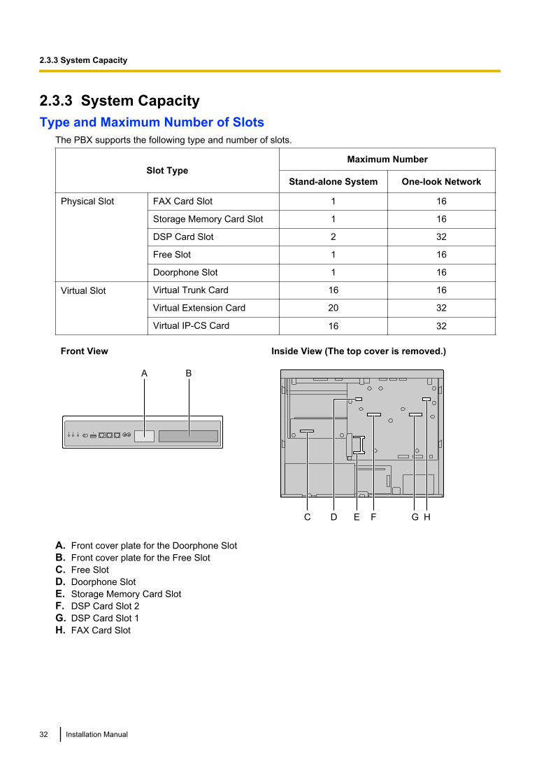
2.3.3 System CapacityType and Maximum Number of Slots
The PBX supports the following type and number of slots.
Slot TypeMaximum Number
Stand-alone System One-look Network
Physical Slot FAX Card Slot 1 16
Storage Memory Card Slot 1 16
DSP Card Slot 2 32
Free Slot 1 16
Doorphone Slot 1 16
Virtual Slot Virtual Trunk Card 16 16
Virtual Extension Card 20 32
Virtual IP-CS Card 16 32
Front View Inside View (The top cover is removed.)
BA
EC D HF G
A. Front cover plate for the Doorphone SlotB. Front cover plate for the Free SlotC. Free SlotD. Doorphone SlotE. Storage Memory Card SlotF. DSP Card Slot 2G. DSP Card Slot 1H. FAX Card Slot
32 Installation Manual
2.3.3 System Capacity
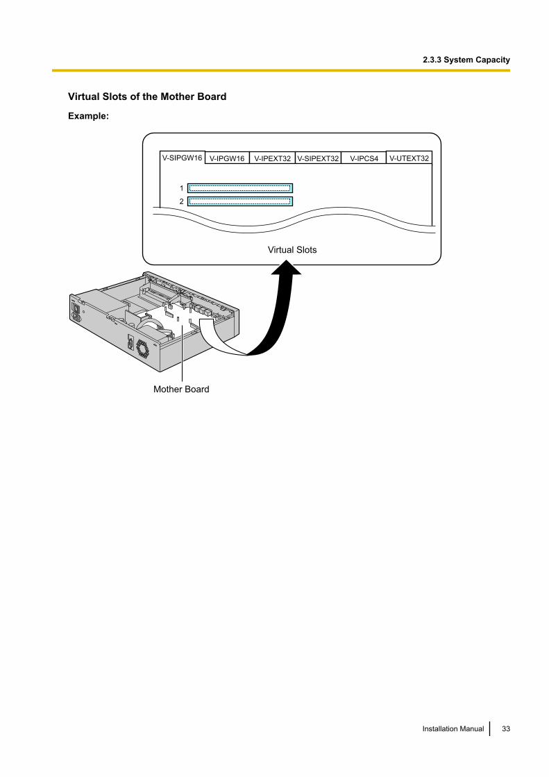
Virtual Slots of the Mother Board
Example:
V-IPGW16 V-IPEXT32 V-SIPEXT32 V-IPCS4 V-UTEXT32
1
2
V-SIPGW16
Virtual Slots
Mother Board
Installation Manual 33
2.3.3 System Capacity
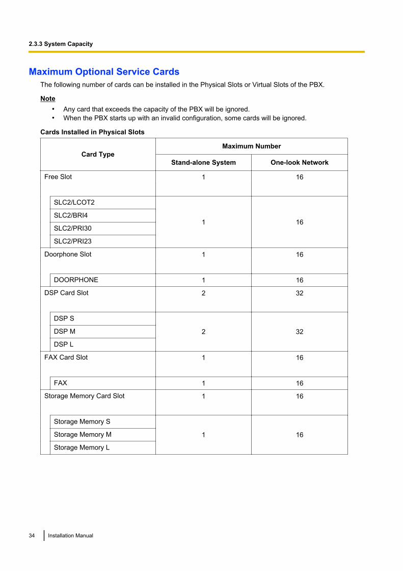
Maximum Optional Service CardsThe following number of cards can be installed in the Physical Slots or Virtual Slots of the PBX.
Note• Any card that exceeds the capacity of the PBX will be ignored.• When the PBX starts up with an invalid configuration, some cards will be ignored.
Cards Installed in Physical Slots
Card TypeMaximum Number
Stand-alone System One-look Network
Free Slot 1 16
SLC2/LCOT2
1 16SLC2/BRI4
SLC2/PRI30
SLC2/PRI23
Doorphone Slot 1 16
DOORPHONE 1 16
DSP Card Slot 2 32
DSP S
2 32DSP M
DSP L
FAX Card Slot 1 16
FAX 1 16
Storage Memory Card Slot 1 16
Storage Memory S
1 16Storage Memory M
Storage Memory L
34 Installation Manual
2.3.3 System Capacity
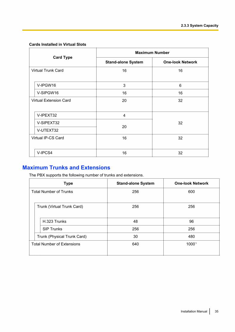
Cards Installed in Virtual Slots
Card TypeMaximum Number
Stand-alone System One-look Network
Virtual Trunk Card 16 16
V-IPGW16 3 6
V-SIPGW16 16 16
Virtual Extension Card 20 32
V-IPEXT32 4
32V-SIPEXT3220
V-UTEXT32
Virtual IP-CS Card 16 32
V-IPCS4 16 32
Maximum Trunks and ExtensionsThe PBX supports the following number of trunks and extensions.
Type Stand-alone System One-look Network
Total Number of Trunks 256 600
Trunk (Virtual Trunk Card) 256 256
H.323 Trunks 48 96
SIP Trunks 256 256
Trunk (Physical Trunk Card) 30 480
Total Number of Extensions 640 1000*1
Installation Manual 35
2.3.3 System Capacity
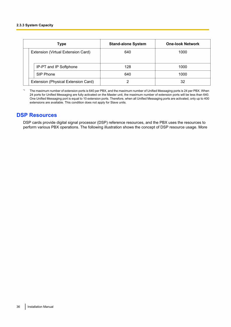
Type Stand-alone System One-look Network
Extension (Virtual Extension Card) 640 1000
IP-PT and IP Softphone 128 1000
SIP Phone 640 1000
Extension (Physical Extension Card) 2 32
*1 The maximum number of extension ports is 640 per PBX, and the maximum number of Unified Messaging ports is 24 per PBX. When24 ports for Unified Messaging are fully activated on the Master unit, the maximum number of extension ports will be less than 640.One Unified Messaging port is equal to 10 extension ports. Therefore, when all Unified Messaging ports are activated, only up to 400extensions are available. This condition does not apply for Slave units.
DSP ResourcesDSP cards provide digital signal processor (DSP) reference resources, and the PBX uses the resources toperform various PBX operations. The following illustration shows the concept of DSP resource usage. More
36 Installation Manual
2.3.3 System Capacity
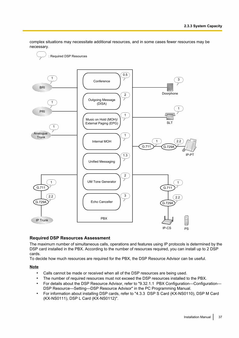
complex situations may necessitate additional resources, and in some cases fewer resources may benecessary.
Conference
0.5
Outgoing Message
(DISA)
2
1
Music on Hold (MOH)/
External Paging (EPG)
1
Internal MOH
Unified Messaging
1.3
PBX
Doorphone
3
1
Analogue
Trunk
2.2
G.729A
G.711
1
IP Trunk
PS
2.2
G.729A
G.711
1
IP-CS
2.2
G.729AG.711
1
IP-PT
1
SLT
1
BRI
1
PRI
: Required DSP Resources
UM Tone Generator
2
Echo Canceller
3
Required DSP Resources AssessmentThe maximum number of simultaneous calls, operations and features using IP protocols is determined by theDSP card installed in the PBX. According to the number of resources required, you can install up to 2 DSPcards.To decide how much resources are required for the PBX, the DSP Resource Advisor can be useful.
Note• Calls cannot be made or received when all of the DSP resources are being used.• The number of required resources must not exceed the DSP resources installed to the PBX.• For details about the DSP Resource Advisor, refer to "9.32.1.1 PBX Configuration—Configuration—
DSP Resource—Setting—DSP Resource Advisor" in the PC Programming Manual.• For information about installing DSP cards, refer to "4.3.3 DSP S Card (KX-NS0110), DSP M Card
(KX-NS0111), DSP L Card (KX-NS0112)".
Installation Manual 37
2.3.3 System Capacity
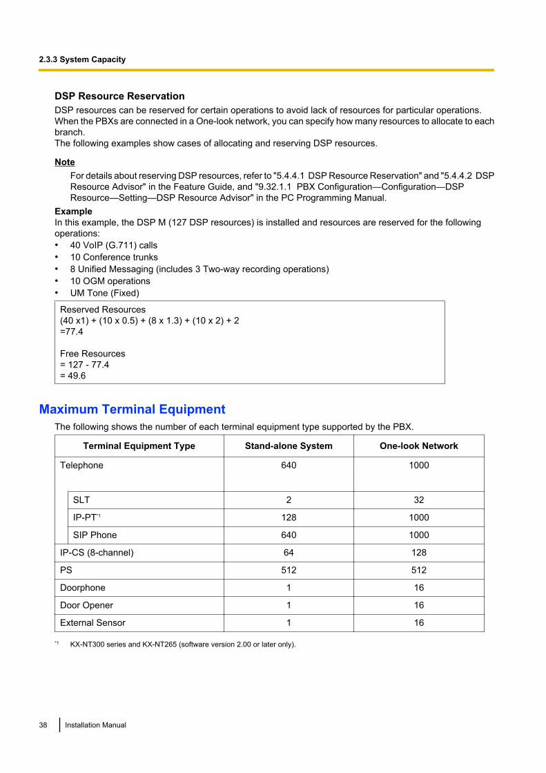
DSP Resource ReservationDSP resources can be reserved for certain operations to avoid lack of resources for particular operations.When the PBXs are connected in a One-look network, you can specify how many resources to allocate to eachbranch.The following examples show cases of allocating and reserving DSP resources.
NoteFor details about reserving DSP resources, refer to "5.4.4.1 DSP Resource Reservation" and "5.4.4.2 DSPResource Advisor" in the Feature Guide, and "9.32.1.1 PBX Configuration—Configuration—DSPResource—Setting—DSP Resource Advisor" in the PC Programming Manual.
ExampleIn this example, the DSP M (127 DSP resources) is installed and resources are reserved for the followingoperations:• 40 VoIP (G.711) calls• 10 Conference trunks• 8 Unified Messaging (includes 3 Two-way recording operations)• 10 OGM operations• UM Tone (Fixed)
Reserved Resources(40 x1) + (10 x 0.5) + (8 x 1.3) + (10 x 2) + 2=77.4
Free Resources= 127 - 77.4= 49.6
Maximum Terminal EquipmentThe following shows the number of each terminal equipment type supported by the PBX.
Terminal Equipment Type Stand-alone System One-look Network
Telephone 640 1000
SLT 2 32
IP-PT*1 128 1000
SIP Phone 640 1000
IP-CS (8-channel) 64 128
PS 512 512
Doorphone 1 16
Door Opener 1 16
External Sensor 1 16
*1 KX-NT300 series and KX-NT265 (software version 2.00 or later only).
38 Installation Manual
2.3.3 System Capacity
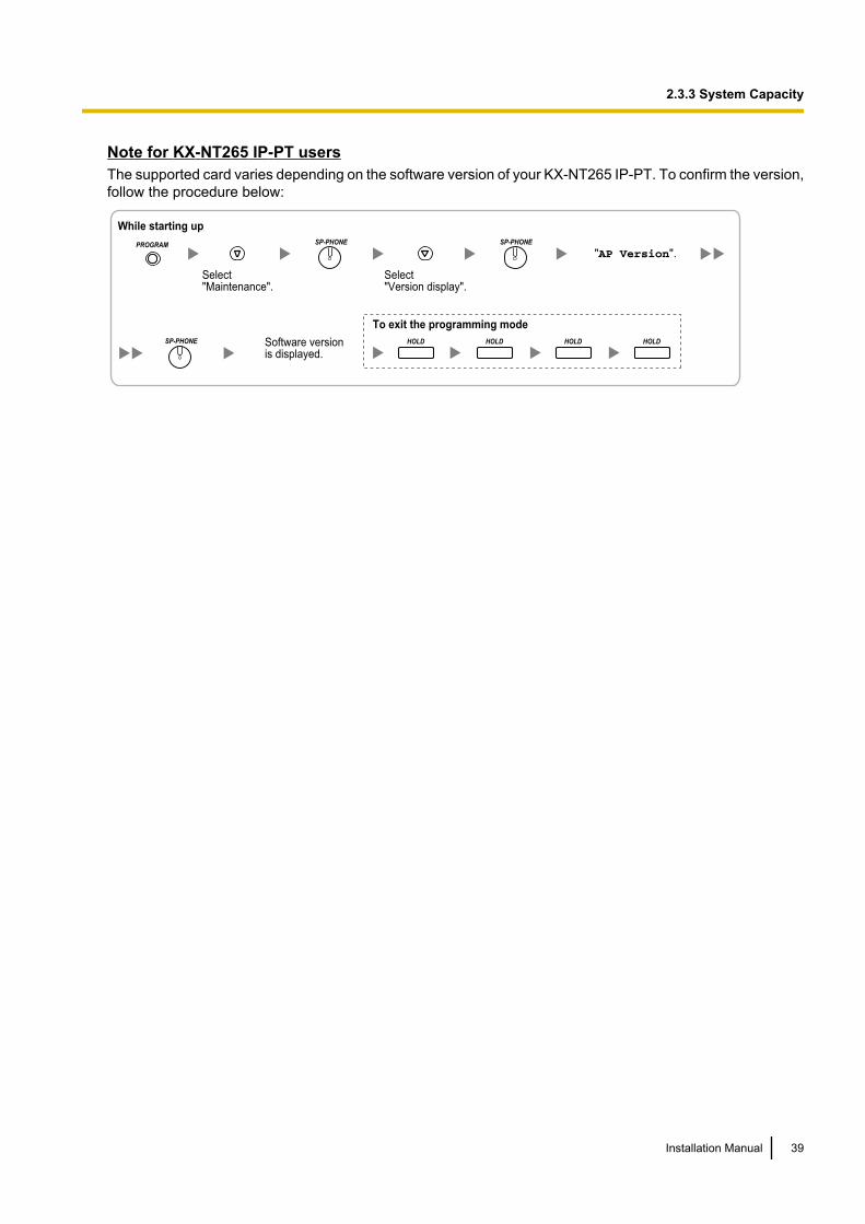
Note for KX-NT265 IP-PT usersThe supported card varies depending on the software version of your KX-NT265 IP-PT. To confirm the version,follow the procedure below:
"AP Version".
Select "Maintenance".
Software version is displayed.
While starting up
Select "Version display".
To exit the programming mode
PROGRAMSP-PHONE
SP-PHONE
SP-PHONE
HOLD HOLD HOLD HOLD
Installation Manual 39
2.3.3 System Capacity

40 Installation Manual
2.3.3 System Capacity

Section 3
Information about the Activation Keys
This section provides information on activation keys,including how to obtain activation keys.
Installation Manual 41
3.1 Information about the Activation KeysTo use IP trunks and IP telephones on a private IP network using the mother board or to upgrade the softwarefor enhanced features, you need the appropriate activation keys.Activation keys are provided via the mother board and the optional activation key files.
3.1.1 Type and Maximum Number of Activation KeysThe PBX supports the following type and number of activation keys. The preinstalled activation keys on themother board are shown with "[ ]".When the number of preinstalled activation keys is not enough for the desired configuration or when you wishto use enhanced features, additional activation keys in the form of activation key files can be installed usingWeb Maintenance Console.When the PBX is connected in a One-look network, activation keys should be installed on the appropriate PBXas shown in the tables below.
Note• Store the downloaded activation key files in your PC or a memory device. They can then be reinstalled
when changing the Storage Memory Card or in an emergency situation.• For information about how to obtain the additional activation keys, refer to "3.1.2 Activation Key Code
and Key Management System".• For information about how to install the activation key files using Web Maintenance Console, refer to
"5.4.4 Installing Additional Activation Keys".
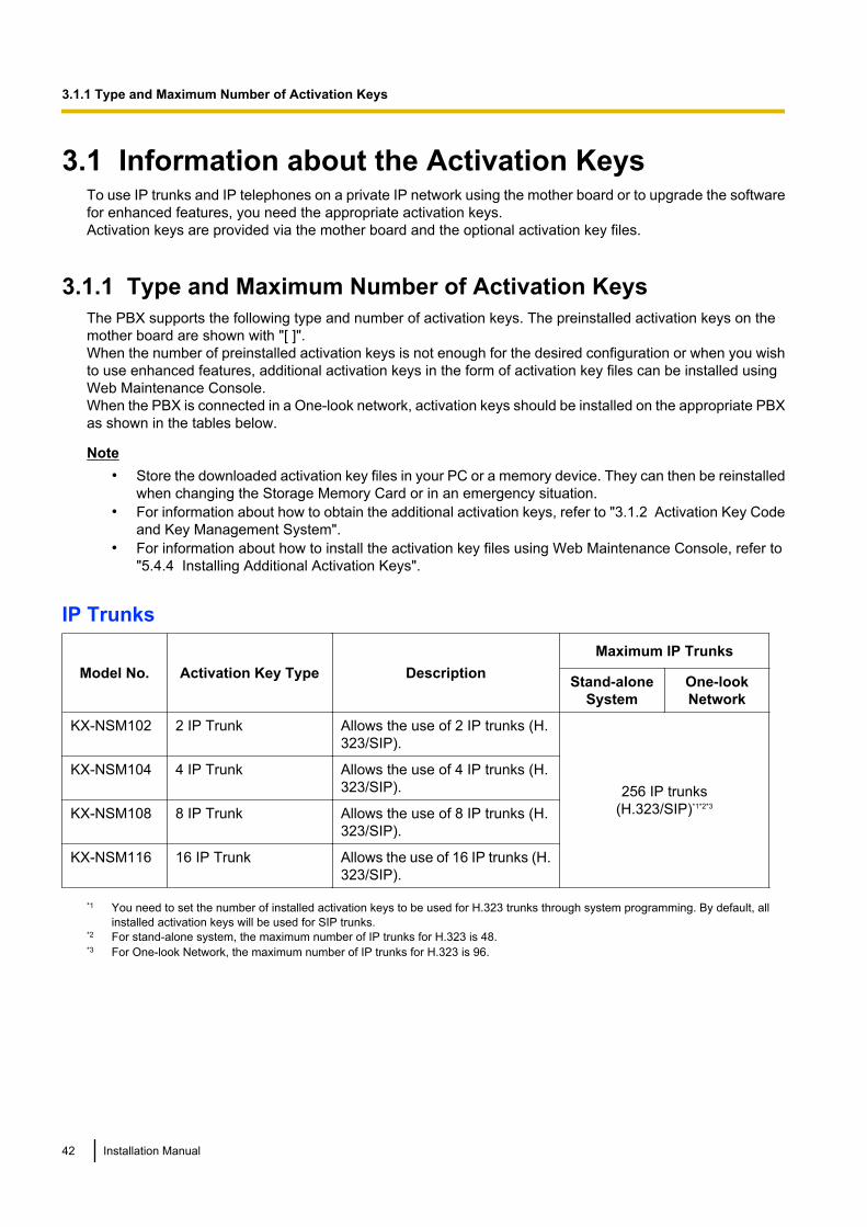
IP Trunks
Model No. Activation Key Type DescriptionMaximum IP Trunks
Stand-aloneSystem
One-lookNetwork
KX-NSM102 2 IP Trunk Allows the use of 2 IP trunks (H.323/SIP).
256 IP trunks(H.323/SIP)*1*2*3
KX-NSM104 4 IP Trunk Allows the use of 4 IP trunks (H.323/SIP).
KX-NSM108 8 IP Trunk Allows the use of 8 IP trunks (H.323/SIP).
KX-NSM116 16 IP Trunk Allows the use of 16 IP trunks (H.323/SIP).
*1 You need to set the number of installed activation keys to be used for H.323 trunks through system programming. By default, allinstalled activation keys will be used for SIP trunks.
*2 For stand-alone system, the maximum number of IP trunks for H.323 is 48.*3 For One-look Network, the maximum number of IP trunks for H.323 is 96.
42 Installation Manual
3.1.1 Type and Maximum Number of Activation Keys
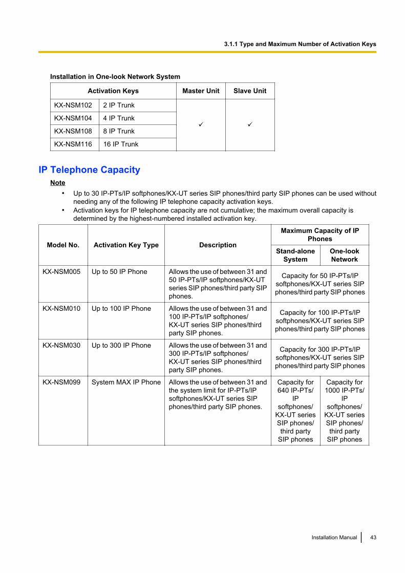
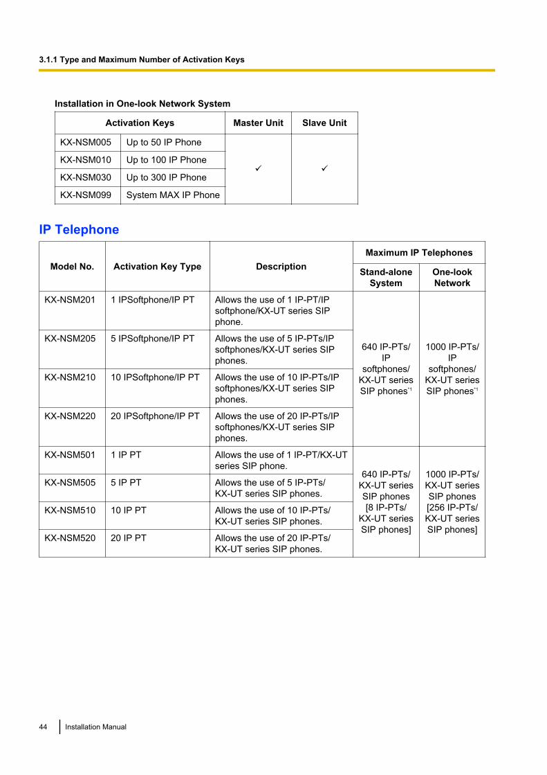
Installation in One-look Network System
Activation Keys Master Unit Slave Unit
KX-NSM102 2 IP Trunk
ü üKX-NSM104 4 IP Trunk
KX-NSM108 8 IP Trunk
KX-NSM116 16 IP Trunk
IP Telephone CapacityNote
• Up to 30 IP-PTs/IP softphones/KX-UT series SIP phones/third party SIP phones can be used withoutneeding any of the following IP telephone capacity activation keys.
• Activation keys for IP telephone capacity are not cumulative; the maximum overall capacity isdetermined by the highest-numbered installed activation key.
Model No. Activation Key Type Description
Maximum Capacity of IPPhones
Stand-aloneSystem
One-lookNetwork
KX-NSM005 Up to 50 IP Phone Allows the use of between 31 and50 IP-PTs/IP softphones/KX-UTseries SIP phones/third party SIPphones.
Capacity for 50 IP-PTs/IPsoftphones/KX-UT series SIPphones/third party SIP phones
KX-NSM010 Up to 100 IP Phone Allows the use of between 31 and100 IP-PTs/IP softphones/KX-UT series SIP phones/thirdparty SIP phones.
Capacity for 100 IP-PTs/IPsoftphones/KX-UT series SIPphones/third party SIP phones
KX-NSM030 Up to 300 IP Phone Allows the use of between 31 and300 IP-PTs/IP softphones/KX-UT series SIP phones/thirdparty SIP phones.
Capacity for 300 IP-PTs/IPsoftphones/KX-UT series SIPphones/third party SIP phones
KX-NSM099 System MAX IP Phone Allows the use of between 31 andthe system limit for IP-PTs/IPsoftphones/KX-UT series SIPphones/third party SIP phones.
Capacity for640 IP-PTs/
IPsoftphones/
KX-UT seriesSIP phones/third party
SIP phones
Capacity for1000 IP-PTs/
IPsoftphones/
KX-UT seriesSIP phones/third party
SIP phones
Installation Manual 43
3.1.1 Type and Maximum Number of Activation Keys
Installation in One-look Network System
Activation Keys Master Unit Slave Unit
KX-NSM005 Up to 50 IP Phone
ü üKX-NSM010 Up to 100 IP Phone
KX-NSM030 Up to 300 IP Phone
KX-NSM099 System MAX IP Phone
IP Telephone
Model No. Activation Key Type DescriptionMaximum IP Telephones
Stand-aloneSystem
One-lookNetwork
KX-NSM201 1 IPSoftphone/IP PT Allows the use of 1 IP-PT/IPsoftphone/KX-UT series SIPphone.
640 IP-PTs/IP
softphones/KX-UT seriesSIP phones*1
1000 IP-PTs/IP
softphones/KX-UT seriesSIP phones*1
KX-NSM205 5 IPSoftphone/IP PT Allows the use of 5 IP-PTs/IPsoftphones/KX-UT series SIPphones.
KX-NSM210 10 IPSoftphone/IP PT Allows the use of 10 IP-PTs/IPsoftphones/KX-UT series SIPphones.
KX-NSM220 20 IPSoftphone/IP PT Allows the use of 20 IP-PTs/IPsoftphones/KX-UT series SIPphones.
KX-NSM501 1 IP PT Allows the use of 1 IP-PT/KX-UTseries SIP phone.
640 IP-PTs/KX-UT seriesSIP phones[8 IP-PTs/
KX-UT seriesSIP phones]
1000 IP-PTs/KX-UT seriesSIP phones[256 IP-PTs/KX-UT seriesSIP phones]
KX-NSM505 5 IP PT Allows the use of 5 IP-PTs/KX-UT series SIP phones.
KX-NSM510 10 IP PT Allows the use of 10 IP-PTs/KX-UT series SIP phones.
KX-NSM520 20 IP PT Allows the use of 20 IP-PTs/KX-UT series SIP phones.
44 Installation Manual
3.1.1 Type and Maximum Number of Activation Keys
Model No. Activation Key Type DescriptionMaximum IP Telephones
Stand-aloneSystem
One-lookNetwork
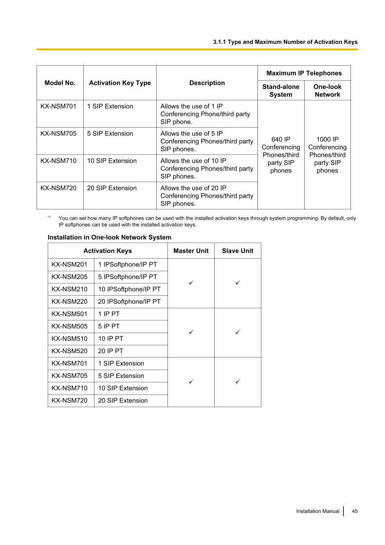
KX-NSM701 1 SIP Extension Allows the use of 1 IPConferencing Phone/third partySIP phone.
640 IPConferencingPhones/third
party SIPphones
1000 IPConferencingPhones/third
party SIPphones
KX-NSM705 5 SIP Extension Allows the use of 5 IPConferencing Phones/third partySIP phones.
KX-NSM710 10 SIP Extension Allows the use of 10 IPConferencing Phones/third partySIP phones.
KX-NSM720 20 SIP Extension Allows the use of 20 IPConferencing Phones/third partySIP phones.
*1 You can set how many IP softphones can be used with the installed activation keys through system programming. By default, onlyIP softphones can be used with the installed activation keys.
Installation in One-look Network System
Activation Keys Master Unit Slave Unit
KX-NSM201 1 IPSoftphone/IP PT
ü üKX-NSM205 5 IPSoftphone/IP PT
KX-NSM210 10 IPSoftphone/IP PT
KX-NSM220 20 IPSoftphone/IP PT
KX-NSM501 1 IP PT
ü üKX-NSM505 5 IP PT
KX-NSM510 10 IP PT
KX-NSM520 20 IP PT
KX-NSM701 1 SIP Extension
ü üKX-NSM705 5 SIP Extension
KX-NSM710 10 SIP Extension
KX-NSM720 20 SIP Extension
Installation Manual 45
3.1.1 Type and Maximum Number of Activation Keys
Networking
Model No. Activation Key Type DescriptionMaximum Activation Keys
Stand-aloneSystem
One-lookNetwork
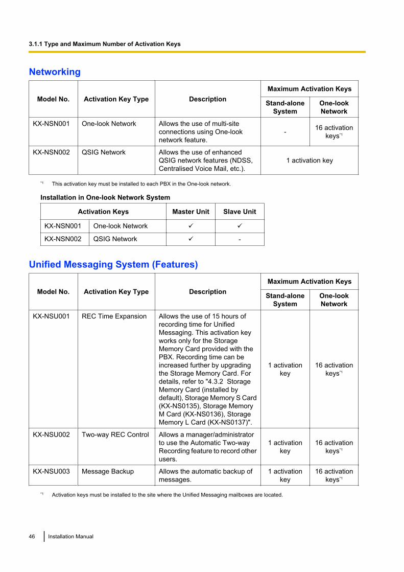
KX-NSN001 One-look Network Allows the use of multi-siteconnections using One-looknetwork feature.
- 16 activationkeys*1
KX-NSN002 QSIG Network Allows the use of enhancedQSIG network features (NDSS,Centralised Voice Mail, etc.).
1 activation key
*1 This activation key must be installed to each PBX in the One-look network.
Installation in One-look Network System
Activation Keys Master Unit Slave Unit
KX-NSN001 One-look Network ü ü
KX-NSN002 QSIG Network ü -
Unified Messaging System (Features)
Model No. Activation Key Type DescriptionMaximum Activation Keys
Stand-aloneSystem
One-lookNetwork
KX-NSU001 REC Time Expansion Allows the use of 15 hours ofrecording time for UnifiedMessaging. This activation keyworks only for the StorageMemory Card provided with thePBX. Recording time can beincreased further by upgradingthe Storage Memory Card. Fordetails, refer to "4.3.2 StorageMemory Card (installed bydefault), Storage Memory S Card(KX-NS0135), Storage MemoryM Card (KX-NS0136), StorageMemory L Card (KX-NS0137)".
1 activationkey
16 activationkeys*1
KX-NSU002 Two-way REC Control Allows a manager/administratorto use the Automatic Two-wayRecording feature to record otherusers.
1 activationkey
16 activationkeys*1
KX-NSU003 Message Backup Allows the automatic backup ofmessages.
1 activationkey
16 activationkeys*1
*1 Activation keys must be installed to the site where the Unified Messaging mailboxes are located.
46 Installation Manual
3.1.1 Type and Maximum Number of Activation Keys
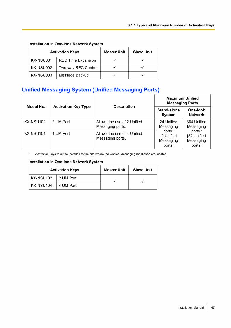
Installation in One-look Network System
Activation Keys Master Unit Slave Unit
KX-NSU001 REC Time Expansion ü ü
KX-NSU002 Two-way REC Control ü ü
KX-NSU003 Message Backup ü ü
Unified Messaging System (Unified Messaging Ports)
Model No. Activation Key Type Description
Maximum UnifiedMessaging Ports
Stand-aloneSystem
One-lookNetwork
KX-NSU102 2 UM Port Allows the use of 2 UnifiedMessaging ports.
24 UnifiedMessaging
ports*1
[2 UnifiedMessaging
ports]
384 UnifiedMessaging
ports*1
[32 UnifiedMessaging
ports]
KX-NSU104 4 UM Port Allows the use of 4 UnifiedMessaging ports.
*1 Activation keys must be installed to the site where the Unified Messaging mailboxes are located.
Installation in One-look Network System
Activation Keys Master Unit Slave Unit
KX-NSU102 2 UM Portü ü
KX-NSU104 4 UM Port
Installation Manual 47
3.1.1 Type and Maximum Number of Activation Keys

Unified Messaging System (Mailbox)
Model No. Activation Key Type DescriptionMaximum Mailboxes
Stand-aloneSystem
One-lookNetwork
KX-NSU201 UM/E-mail 1 User*1 Allows the use of an e-mail(IMAP4) client and e-mailnotification (voice/fax messages)for 1 user.
1024mailboxes
16 384mailboxes
KX-NSU205 UM/E-mail 5 Users*1 Allows the use of an e-mail(IMAP4) client and e-mailnotification (voice/fax messages)for 5 users.
KX-NSU210 UM/E-mail 10 Users*1 Allows the use of an e-mail(IMAP4) client and e-mailnotification (voice/fax messages)for 10 users.
KX-NSU220 UM/E-mail 20 Users*1 Allows the use of an e-mail(IMAP4) client and e-mailnotification (voice/fax messages)for 20 users.
KX-NSU299 UM/E-mail All Users*1 Allows the use of an e-mail(IMAP4) client and e-mailnotification (voice/fax messages)up to the system’s limit.
*1 Activation keys must be installed to the site where the Unified Messaging mailboxes are located.
Installation in One-look Network System
Activation Keys Master Unit Slave Unit
KX-NSU201 UM/E-mail 1 User
ü ü
KX-NSU205 UM/E-mail 5 Users
KX-NSU210 UM/E-mail 10 Users
KX-NSU220 UM/E-mail 20 Users
KX-NSU299 UM/E-mail All Users
48 Installation Manual
3.1.1 Type and Maximum Number of Activation Keys
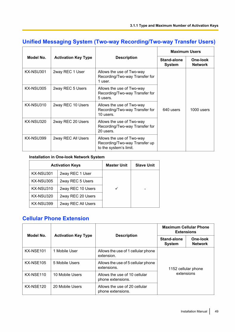
Unified Messaging System (Two-way Recording/Two-way Transfer Users)
Model No. Activation Key Type DescriptionMaximum Users
Stand-aloneSystem
One-lookNetwork
KX-NSU301 2way REC 1 User Allows the use of Two-wayRecording/Two-way Transfer for1 user.
640 users 1000 users
KX-NSU305 2way REC 5 Users Allows the use of Two-wayRecording/Two-way Transfer for5 users.
KX-NSU310 2way REC 10 Users Allows the use of Two-wayRecording/Two-way Transfer for10 users.
KX-NSU320 2way REC 20 Users Allows the use of Two-wayRecording/Two-way Transfer for20 users.
KX-NSU399 2way REC All Users Allows the use of Two-wayRecording/Two-way Transfer upto the system’s limit.
Installation in One-look Network System
Activation Keys Master Unit Slave Unit
KX-NSU301 2way REC 1 User
ü -
KX-NSU305 2way REC 5 Users
KX-NSU310 2way REC 10 Users
KX-NSU320 2way REC 20 Users
KX-NSU399 2way REC All Users
Cellular Phone Extension
Model No. Activation Key Type Description
Maximum Cellular PhoneExtensions
Stand-aloneSystem
One-lookNetwork
KX-NSE101 1 Mobile User Allows the use of 1 cellular phoneextension.
1152 cellular phoneextensions
KX-NSE105 5 Mobile Users Allows the use of 5 cellular phoneextensions.
KX-NSE110 10 Mobile Users Allows the use of 10 cellularphone extensions.
KX-NSE120 20 Mobile Users Allows the use of 20 cellularphone extensions.
Installation Manual 49
3.1.1 Type and Maximum Number of Activation Keys
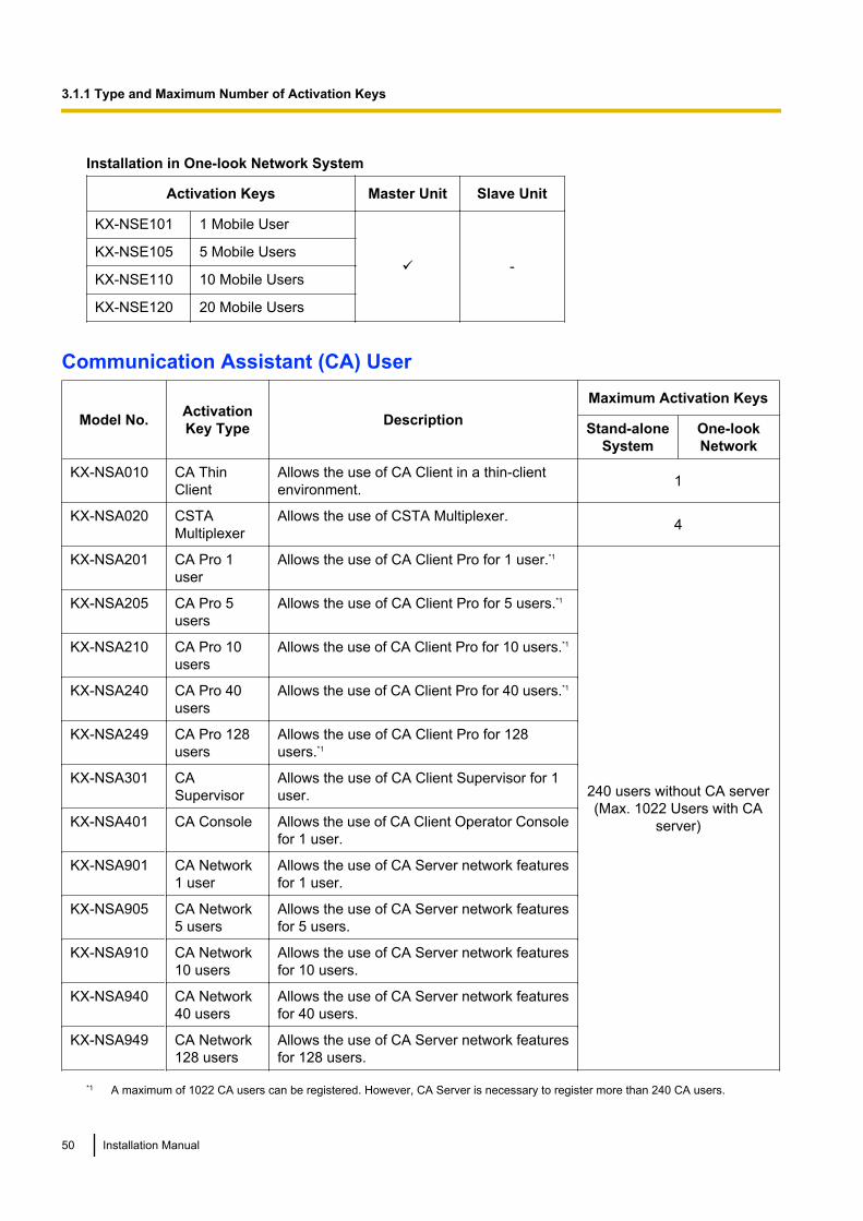
Installation in One-look Network System
Activation Keys Master Unit Slave Unit
KX-NSE101 1 Mobile User
ü -KX-NSE105 5 Mobile Users
KX-NSE110 10 Mobile Users
KX-NSE120 20 Mobile Users
Communication Assistant (CA) User
Model No. ActivationKey Type Description
Maximum Activation Keys
Stand-aloneSystem
One-lookNetwork
KX-NSA010 CA ThinClient
Allows the use of CA Client in a thin-clientenvironment. 1
KX-NSA020 CSTAMultiplexer
Allows the use of CSTA Multiplexer. 4
KX-NSA201 CA Pro 1user
Allows the use of CA Client Pro for 1 user.*1
240 users without CA server(Max. 1022 Users with CA
server)
KX-NSA205 CA Pro 5users
Allows the use of CA Client Pro for 5 users.*1
KX-NSA210 CA Pro 10users
Allows the use of CA Client Pro for 10 users.*1
KX-NSA240 CA Pro 40users
Allows the use of CA Client Pro for 40 users.*1
KX-NSA249 CA Pro 128users
Allows the use of CA Client Pro for 128users.*1
KX-NSA301 CASupervisor
Allows the use of CA Client Supervisor for 1user.
KX-NSA401 CA Console Allows the use of CA Client Operator Consolefor 1 user.
KX-NSA901 CA Network1 user
Allows the use of CA Server network featuresfor 1 user.
KX-NSA905 CA Network5 users
Allows the use of CA Server network featuresfor 5 users.
KX-NSA910 CA Network10 users
Allows the use of CA Server network featuresfor 10 users.
KX-NSA940 CA Network40 users
Allows the use of CA Server network featuresfor 40 users.
KX-NSA949 CA Network128 users
Allows the use of CA Server network featuresfor 128 users.
*1 A maximum of 1022 CA users can be registered. However, CA Server is necessary to register more than 240 CA users.
50 Installation Manual
3.1.1 Type and Maximum Number of Activation Keys
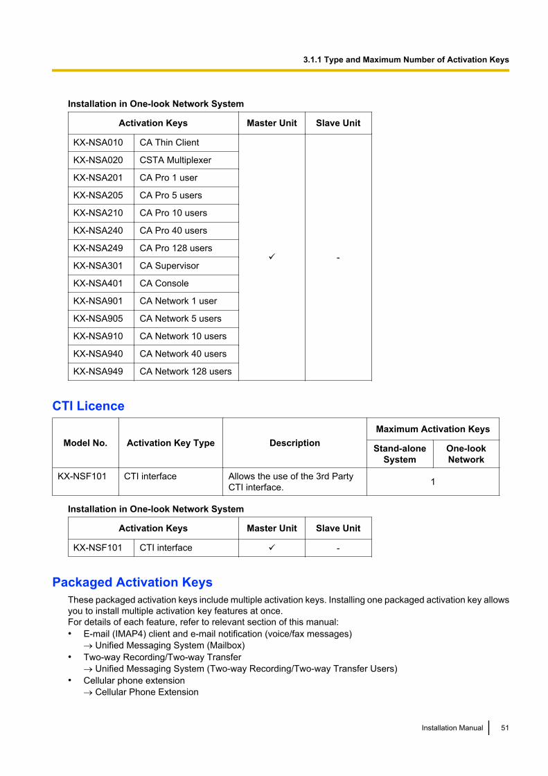
Installation in One-look Network System
Activation Keys Master Unit Slave Unit
KX-NSA010 CA Thin Client
ü -
KX-NSA020 CSTA Multiplexer
KX-NSA201 CA Pro 1 user
KX-NSA205 CA Pro 5 users
KX-NSA210 CA Pro 10 users
KX-NSA240 CA Pro 40 users
KX-NSA249 CA Pro 128 users
KX-NSA301 CA Supervisor
KX-NSA401 CA Console
KX-NSA901 CA Network 1 user
KX-NSA905 CA Network 5 users
KX-NSA910 CA Network 10 users
KX-NSA940 CA Network 40 users
KX-NSA949 CA Network 128 users
CTI Licence
Model No. Activation Key Type DescriptionMaximum Activation Keys
Stand-aloneSystem
One-lookNetwork
KX-NSF101 CTI interface Allows the use of the 3rd PartyCTI interface. 1
Installation in One-look Network System
Activation Keys Master Unit Slave Unit
KX-NSF101 CTI interface ü -
Packaged Activation KeysThese packaged activation keys include multiple activation keys. Installing one packaged activation key allowsyou to install multiple activation key features at once.For details of each feature, refer to relevant section of this manual:• E-mail (IMAP4) client and e-mail notification (voice/fax messages)
® Unified Messaging System (Mailbox)• Two-way Recording/Two-way Transfer
® Unified Messaging System (Two-way Recording/Two-way Transfer Users)• Cellular phone extension
® Cellular Phone Extension
Installation Manual 51
3.1.1 Type and Maximum Number of Activation Keys
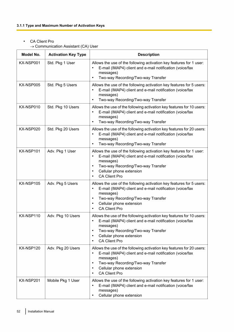
• CA Client Pro® Communication Assistant (CA) User
Model No. Activation Key Type Description
KX-NSP001 Std. Pkg 1 User Allows the use of the following activation key features for 1 user:• E-mail (IMAP4) client and e-mail notification (voice/fax
messages)• Two-way Recording/Two-way Transfer
KX-NSP005 Std. Pkg 5 Users Allows the use of the following activation key features for 5 users:• E-mail (IMAP4) client and e-mail notification (voice/fax
messages)• Two-way Recording/Two-way Transfer
KX-NSP010 Std. Pkg 10 Users Allows the use of the following activation key features for 10 users:• E-mail (IMAP4) client and e-mail notification (voice/fax
messages)• Two-way Recording/Two-way Transfer
KX-NSP020 Std. Pkg 20 Users Allows the use of the following activation key features for 20 users:• E-mail (IMAP4) client and e-mail notification (voice/fax
messages)• Two-way Recording/Two-way Transfer
KX-NSP101 Adv. Pkg 1 User Allows the use of the following activation key features for 1 user:• E-mail (IMAP4) client and e-mail notification (voice/fax
messages)• Two-way Recording/Two-way Transfer• Cellular phone extension• CA Client Pro
KX-NSP105 Adv. Pkg 5 Users Allows the use of the following activation key features for 5 users:• E-mail (IMAP4) client and e-mail notification (voice/fax
messages)• Two-way Recording/Two-way Transfer• Cellular phone extension• CA Client Pro
KX-NSP110 Adv. Pkg 10 Users Allows the use of the following activation key features for 10 users:• E-mail (IMAP4) client and e-mail notification (voice/fax
messages)• Two-way Recording/Two-way Transfer• Cellular phone extension• CA Client Pro
KX-NSP120 Adv. Pkg 20 Users Allows the use of the following activation key features for 20 users:• E-mail (IMAP4) client and e-mail notification (voice/fax
messages)• Two-way Recording/Two-way Transfer• Cellular phone extension• CA Client Pro
KX-NSP201 Mobile Pkg 1 User Allows the use of the following activation key features for 1 user:• E-mail (IMAP4) client and e-mail notification (voice/fax
messages)• Cellular phone extension
52 Installation Manual
3.1.1 Type and Maximum Number of Activation Keys
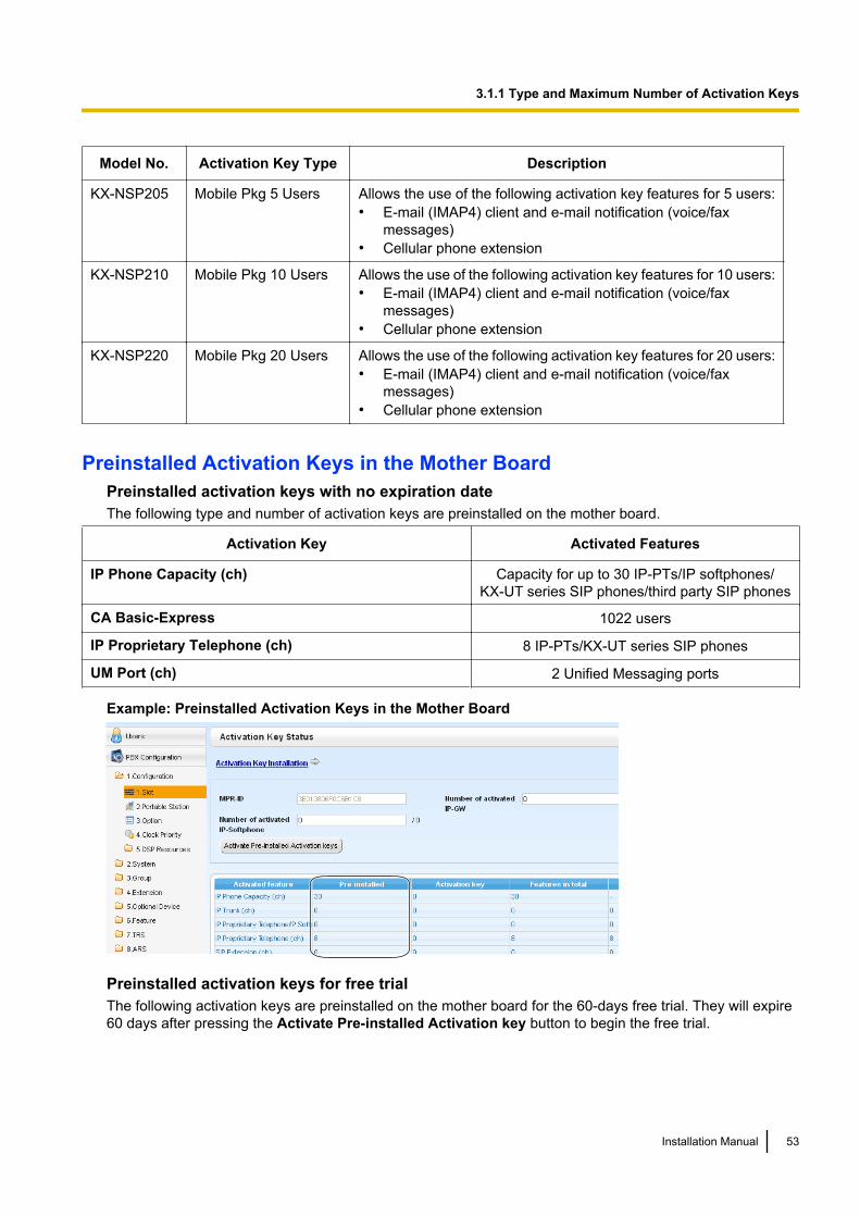
Model No. Activation Key Type Description
KX-NSP205 Mobile Pkg 5 Users Allows the use of the following activation key features for 5 users:• E-mail (IMAP4) client and e-mail notification (voice/fax
messages)• Cellular phone extension
KX-NSP210 Mobile Pkg 10 Users Allows the use of the following activation key features for 10 users:• E-mail (IMAP4) client and e-mail notification (voice/fax
messages)• Cellular phone extension
KX-NSP220 Mobile Pkg 20 Users Allows the use of the following activation key features for 20 users:• E-mail (IMAP4) client and e-mail notification (voice/fax
messages)• Cellular phone extension
Preinstalled Activation Keys in the Mother BoardPreinstalled activation keys with no expiration dateThe following type and number of activation keys are preinstalled on the mother board.
Activation Key Activated Features
IP Phone Capacity (ch) Capacity for up to 30 IP-PTs/IP softphones/KX-UT series SIP phones/third party SIP phones
CA Basic-Express 1022 users
IP Proprietary Telephone (ch) 8 IP-PTs/KX-UT series SIP phones
UM Port (ch) 2 Unified Messaging ports
Example: Preinstalled Activation Keys in the Mother Board
Preinstalled activation keys for free trialThe following activation keys are preinstalled on the mother board for the 60-days free trial. They will expire60 days after pressing the Activate Pre-installed Activation key button to begin the free trial.
Installation Manual 53
3.1.1 Type and Maximum Number of Activation Keys
Activation Key Activated Features
One-look Network One-look networking feature
Two-way Recording Control Automatic Two-way Recording feature
Message Backup Automatic backup of messages
UM/E-mail (128 user) 128 mailboxes
Two-Way Recording (30 users) 30 Two-way Recording/Two-way Transfer users
Mobile Extension (30 users) 30 cellular phone extensions
CA PRO (128 users) 128 CA Pro users
CA Supervisor (1 user) 1 CA Supervisor user
CA Operator Console (1 user) 1 CA Console user
CA Thin Client Server Use CA in a thin-client environment
CSTA Multiplexer Multiplexing for CSTA connections
Activation Key Installation ExampleThe following illustration shows an example of when using 16 SIP trunks, 16 H.323 trunks, 40 IP-PTs, 20 IPsoftphones, and 20 KX-UT series SIP phones on a private IP network using the mother board.
54 Installation Manual
3.1.1 Type and Maximum Number of Activation Keys
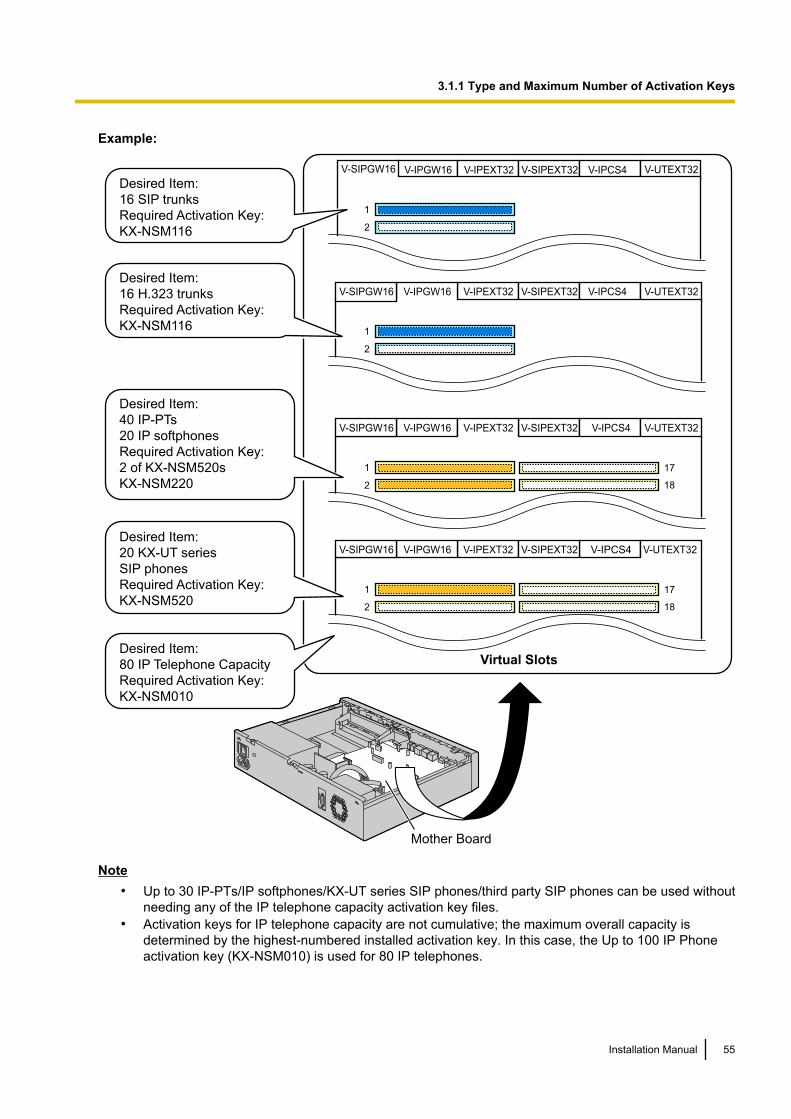
Example:
Mother Board
V-IPGW16 V-IPEXT32 V-SIPEXT32 V-IPCS4 V-UTEXT32
1
2
V-SIPGW16
Desired Item:
16 SIP trunks
Required Activation Key:
KX-NSM116
V-IPEXT32 V-SIPEXT32 V-IPCS4 V-UTEXT32V-IPGW16
1
2
V-SIPGW16
Desired Item:
16 H.323 trunks
Required Activation Key:
KX-NSM116
V-IPGW16 V-SIPEXT32 V-IPCS4 V-UTEXT32V-IPEXT32
1
2
V-SIPGW16
17
18
Desired Item:
40 IP-PTs
20 IP softphones
Required Activation Key:
2 of KX-NSM520s
KX-NSM220
V-IPGW16 V-UTEXT32
1
2
V-SIPGW16
17
18
V-IPEXT32 V-SIPEXT32 V-IPCS4Desired Item:
20 KX-UT series
SIP phones
Required Activation Key:
KX-NSM520
Desired Item:
80 IP Telephone Capacity
Required Activation Key:
KX-NSM010
Virtual Slots
Note• Up to 30 IP-PTs/IP softphones/KX-UT series SIP phones/third party SIP phones can be used without
needing any of the IP telephone capacity activation key files.• Activation keys for IP telephone capacity are not cumulative; the maximum overall capacity is
determined by the highest-numbered installed activation key. In this case, the Up to 100 IP Phoneactivation key (KX-NSM010) is used for 80 IP telephones.
Installation Manual 55
3.1.1 Type and Maximum Number of Activation Keys
3.1.2 Activation Key Code and Key Management SystemTo obtain additional activation keys, you need to purchase the appropriate activation key codes and accessthe Key Management System. You can download the activation keys as an activation key file from the KeyManagement System.To download the activation keys, enter the MPR ID number shown on the back of the main unit, and activationkey number and registration ID provided on each activation key code.For information about the type of activation key codes available, refer to "3.1.1 Type and Maximum Numberof Activation Keys".For details about installing the downloaded activation key file(s) in the Storage Memory Card using WebMaintenance Console, refer to "5.4.4 Installing Additional Activation Keys".
Note• You can only download the activation key file once using the activation key number and registration ID
provided on the activation key code.• Up to 8 activation keys can be downloaded as one activation key file.• Up to 997 activation key files can be installed in the optional upgrade Storage Memory Card.• It is possible to send the activation key file to a specified e-mail address at the same time as
downloading it to a PC.• Make sure to backup the downloaded activation key files on your PC.• When the mother board has to be replaced due to a system malfunction, the MPR-ID for the mother
board is no longer valid. In this case, you need a temporary activation key for maintenance purposes.The temporary activation key can only be used for a limited time period, and can be downloaded fromthe Key Management System in the same way as downloading activation key files.
56 Installation Manual
3.1.2 Activation Key Code and Key Management System
Section 4
Installation
This section describes the procedures to install thePBX. Detailed instructions for planning the installationsite, installing the main unit and optional service cards,and cabling of peripheral equipment are provided.Further information on peripheral equipment installationis included.
Installation Manual 57
4.1 Before Installation
4.1.1 Before InstallationPlease read the following notes concerning installation and connection before installing the PBX and terminalequipment.Be sure to comply with all applicable laws, regulations, and guidelines.
NoticePanasonic assumes no responsibility for injuries or property damage resulting from failures arising out ofimproper installation or operation inconsistent with this documentation.
Safety Installation InstructionsWARNING
When installing telephone wiring, basic safety precautions should always be followed to reducethe risk of fire, electric shock and injury to persons, including the following:• Never install telephone wiring during a lightning storm.• Never install telephone jacks in wet locations unless the jack is specifically designed for wet
locations.• Never touch uninsulated telephone wires or terminals unless the telephone line has been
disconnected at the network interface.• Use caution when installing or modifying telephone lines.• Anti-static precautions should be taken during installation.
Installation PrecautionsThe PBX is suitable for mounting on a 19-inch rack, mounting on a wall, or placing on a desktop, and shouldbe installed in a location where it is accessible for inspections and maintenance.To prevent malfunction, noise, or discolouration, follow the instructions below:
WARNINGDo not install the system in the following locations:• Areas where shocks or vibrations are frequent or strong. Such activity may lead to the product
falling over and causing injury, or may impair the product’s performance.• Areas with high amounts of dust. High amounts of dust can lead to fire or electric shock, and
impair the performance of the product.
CAUTIONDo not install the system in the following locations:• In direct sunlight and hot, cold, or humid places. (Temperature range: 0 °C to 40 °C)• Areas where sulphuric gases may be present, such as near thermal springs.• Near devices that generate high frequencies, such as sewing machines or electric welders.• Locations where other objects will obstruct the area around the PBX. Be especially careful to leave at
least 5 cm to the sides of the PBX for ventilation.
NoticeDo not install the system in the following locations:• On or near computers, or other office equipment, as well as microwave ovens or air conditioners. (It is
preferable not to install the system in the same room as the above equipment.)
58 Installation Manual
4.1.1 Before Installation
• Within 1.8 m of radios and televisions. (Both the PBX and PTs should be at least 1.8 m away from suchdevices.)
Do not perform the following:• Do not block the openings of the PBX.• Do not stack up the optional service cards.
Wiring PrecautionsBe sure to follow these instructions when wiring the unit:
CAUTION• Avoid using the same AC outlet for computers and other office equipment, as noise generated by such
equipment may hamper system performance or interrupt the system.• Unplug the system from its power source when wiring, and plug the system back in only after all wiring
is completed.• Trunks should be installed with surge protectors. For details, refer to "4.2.12 Surge Protector
Installation".
Notice• Use 1-pair telephone cables when connecting SLTs, data terminals, answering machines, computers,
etc.• Mis-wiring may cause the PBX to operate improperly. Refer to "Section 4 Installation" when wiring
the system.• If an extension does not operate properly, disconnect the telephone from the extension line and connect
it again, or turn off the PBX using the power switch, then turn it on again.• Use twisted pair cable for trunk connection.• To prevent signal noise from interfering with the performance of the product, do not run unshielded
telephone cables near AC power cables, computer cables, AC power sources, etc. When runningcables near other noise-generating devices or cables, use shielded telephone cables or shield thetelephone cables with metal tubing.
Preparing the Network EnvironmentBe sure to prepare your network’s environment for the installation of the PBX according to the intended PBXnetworking configuration. For details about PBX network configurations, refer to "Section 7 Appendix".
Installation Manual 59
4.1.1 Before Installation
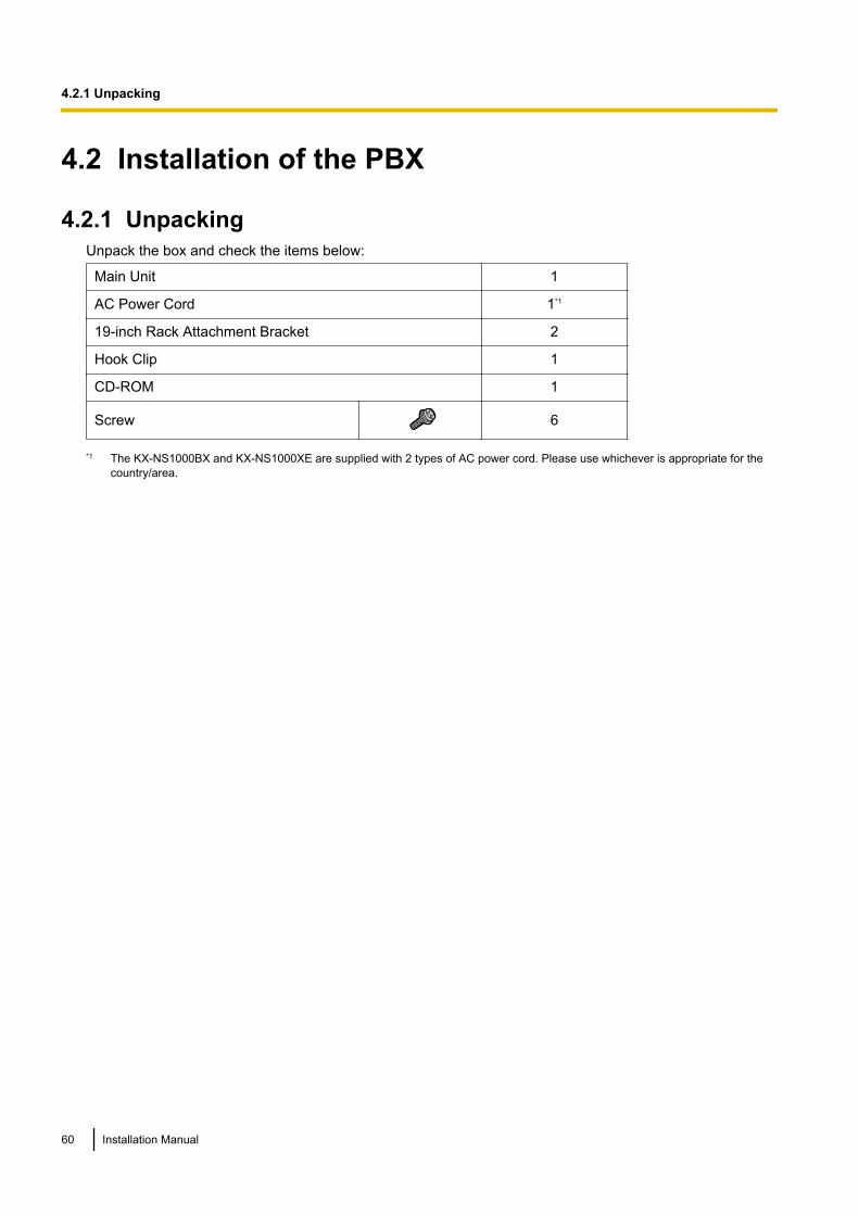
4.2 Installation of the PBX
4.2.1 UnpackingUnpack the box and check the items below:
Main Unit 1
AC Power Cord 1*1
19-inch Rack Attachment Bracket 2
Hook Clip 1
CD-ROM 1
Screw 6
*1 The KX-NS1000BX and KX-NS1000XE are supplied with 2 types of AC power cord. Please use whichever is appropriate for thecountry/area.
60 Installation Manual
4.2.1 Unpacking
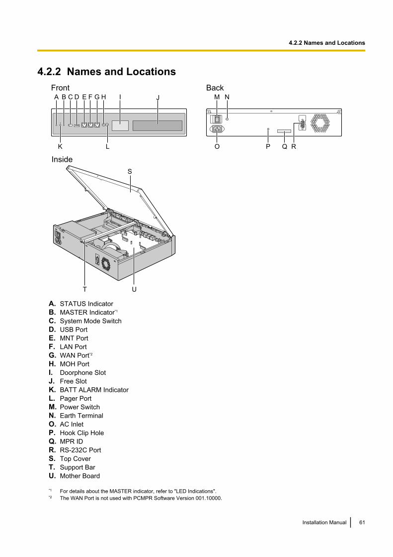
4.2.2 Names and LocationsFront
C D EA B
K
F G H
L
I J
UT
S
Inside
BackM N
O RP Q
A. STATUS IndicatorB. MASTER Indicator*1
C. System Mode SwitchD. USB PortE. MNT PortF. LAN PortG. WAN Port*2
H. MOH PortI. Doorphone SlotJ. Free SlotK. BATT ALARM IndicatorL. Pager PortM. Power SwitchN. Earth TerminalO. AC InletP. Hook Clip HoleQ. MPR IDR. RS-232C PortS. Top CoverT. Support BarU. Mother Board
*1 For details about the MASTER indicator, refer to "LED Indications".*2 The WAN Port is not used with PCMPR Software Version 001.10000.
Installation Manual 61
4.2.2 Names and Locations
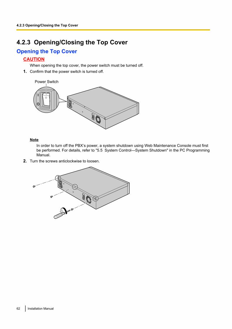
4.2.3 Opening/Closing the Top CoverOpening the Top Cover
CAUTIONWhen opening the top cover, the power switch must be turned off.
1. Confirm that the power switch is turned off.
Power Switch
NoteIn order to turn off the PBX’s power, a system shutdown using Web Maintenance Console must firstbe performed. For details, refer to "5.5 System Control—System Shutdown" in the PC ProgrammingManual.
2. Turn the screws anticlockwise to loosen.
62 Installation Manual
4.2.3 Opening/Closing the Top Cover
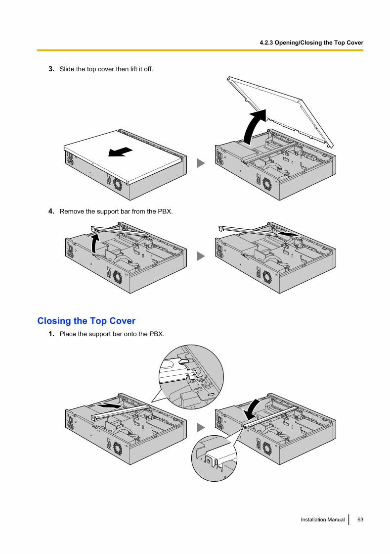
3. Slide the top cover then lift it off.
4. Remove the support bar from the PBX.
Closing the Top Cover1. Place the support bar onto the PBX.
Installation Manual 63
4.2.3 Opening/Closing the Top Cover
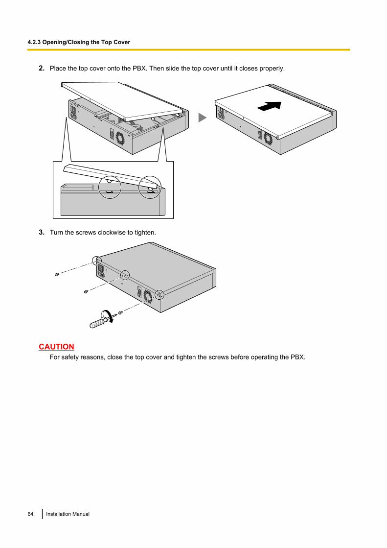
2. Place the top cover onto the PBX. Then slide the top cover until it closes properly.
3. Turn the screws clockwise to tighten.
CAUTIONFor safety reasons, close the top cover and tighten the screws before operating the PBX.
64 Installation Manual
4.2.3 Opening/Closing the Top Cover
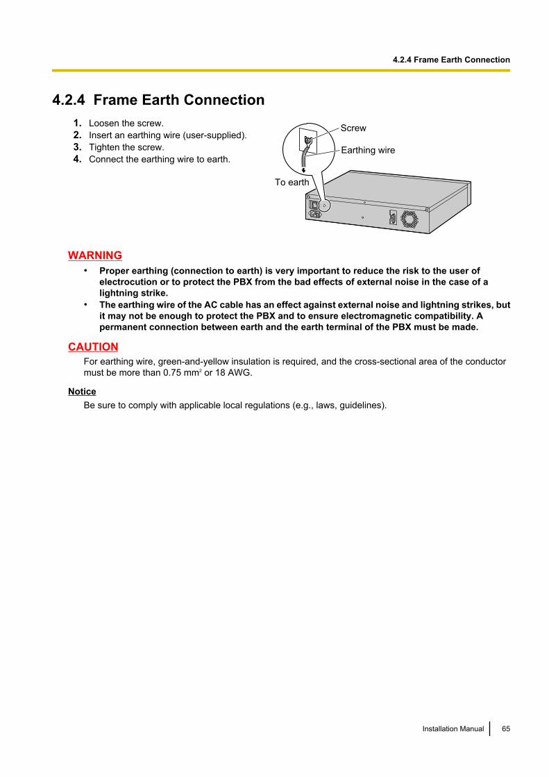
4.2.4 Frame Earth Connection1. Loosen the screw.2. Insert an earthing wire (user-supplied).3. Tighten the screw.4. Connect the earthing wire to earth.
Screw
Earthing wire
To earth
WARNING• Proper earthing (connection to earth) is very important to reduce the risk to the user of
electrocution or to protect the PBX from the bad effects of external noise in the case of alightning strike.
• The earthing wire of the AC cable has an effect against external noise and lightning strikes, butit may not be enough to protect the PBX and to ensure electromagnetic compatibility. Apermanent connection between earth and the earth terminal of the PBX must be made.
CAUTIONFor earthing wire, green-and-yellow insulation is required, and the cross-sectional area of the conductormust be more than 0.75 mm2 or 18 AWG.
NoticeBe sure to comply with applicable local regulations (e.g., laws, guidelines).
Installation Manual 65
4.2.4 Frame Earth Connection
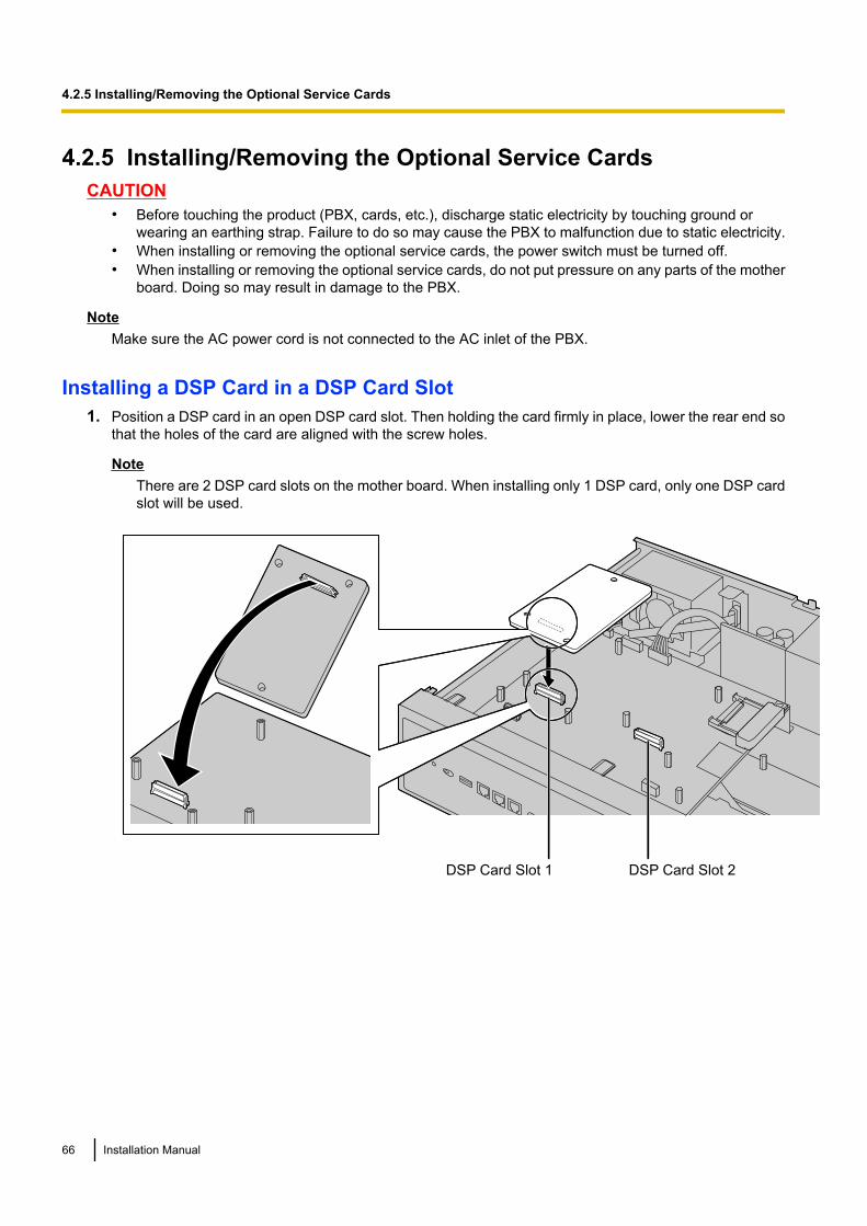
4.2.5 Installing/Removing the Optional Service CardsCAUTION
• Before touching the product (PBX, cards, etc.), discharge static electricity by touching ground orwearing an earthing strap. Failure to do so may cause the PBX to malfunction due to static electricity.
• When installing or removing the optional service cards, the power switch must be turned off.• When installing or removing the optional service cards, do not put pressure on any parts of the mother
board. Doing so may result in damage to the PBX.
NoteMake sure the AC power cord is not connected to the AC inlet of the PBX.
Installing a DSP Card in a DSP Card Slot1. Position a DSP card in an open DSP card slot. Then holding the card firmly in place, lower the rear end so
that the holes of the card are aligned with the screw holes.
NoteThere are 2 DSP card slots on the mother board. When installing only 1 DSP card, only one DSP cardslot will be used.
DSP Card Slot 1 DSP Card Slot 2
66 Installation Manual
4.2.5 Installing/Removing the Optional Service Cards
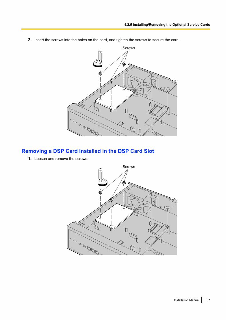
2. Insert the screws into the holes on the card, and tighten the screws to secure the card.
Screws
Removing a DSP Card Installed in the DSP Card Slot1. Loosen and remove the screws.
Screws
Installation Manual 67
4.2.5 Installing/Removing the Optional Service Cards
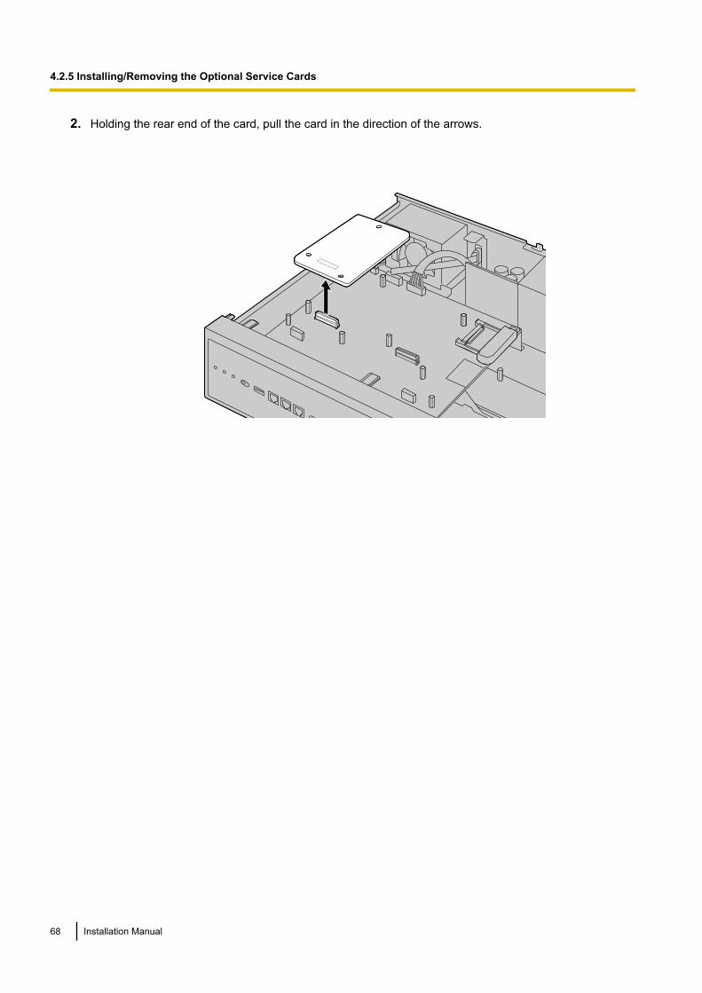
2. Holding the rear end of the card, pull the card in the direction of the arrows.
68 Installation Manual
4.2.5 Installing/Removing the Optional Service Cards
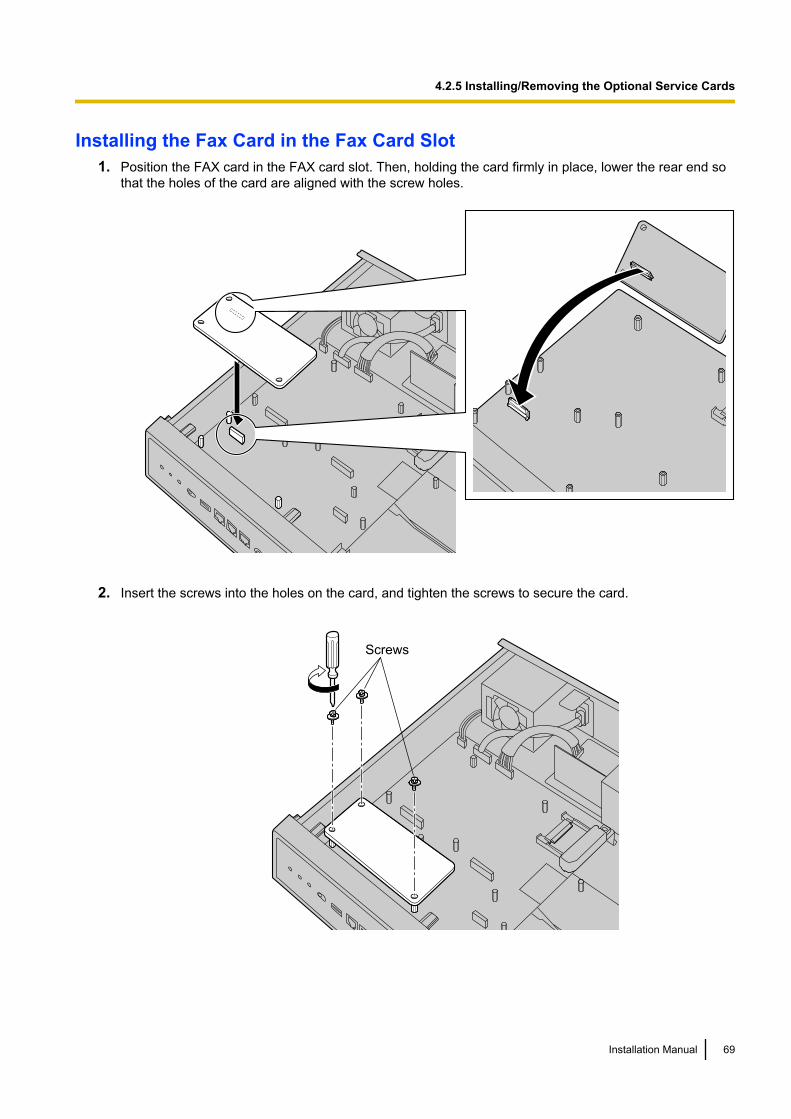
Installing the Fax Card in the Fax Card Slot1. Position the FAX card in the FAX card slot. Then, holding the card firmly in place, lower the rear end so
that the holes of the card are aligned with the screw holes.
2. Insert the screws into the holes on the card, and tighten the screws to secure the card.
Screws
Installation Manual 69
4.2.5 Installing/Removing the Optional Service Cards
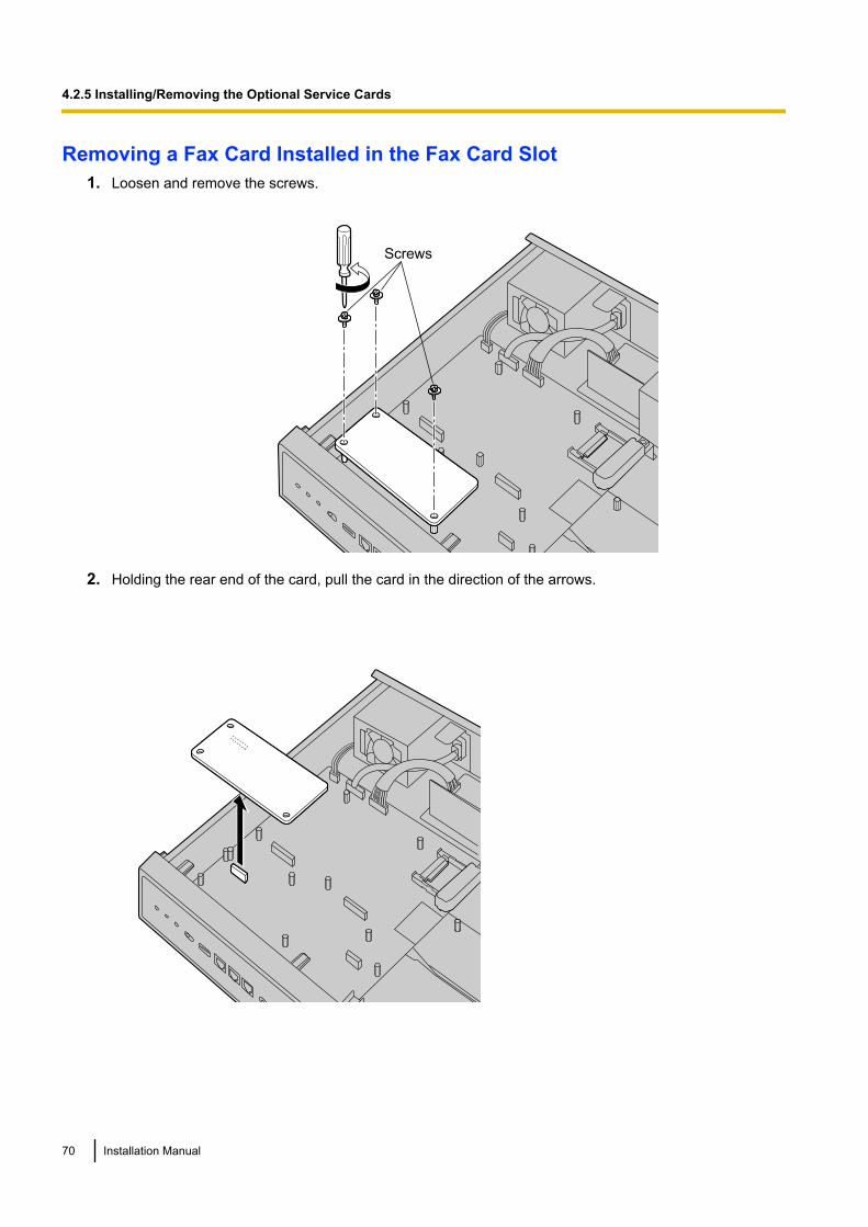
Removing a Fax Card Installed in the Fax Card Slot1. Loosen and remove the screws.
Screws
2. Holding the rear end of the card, pull the card in the direction of the arrows.
70 Installation Manual
4.2.5 Installing/Removing the Optional Service Cards
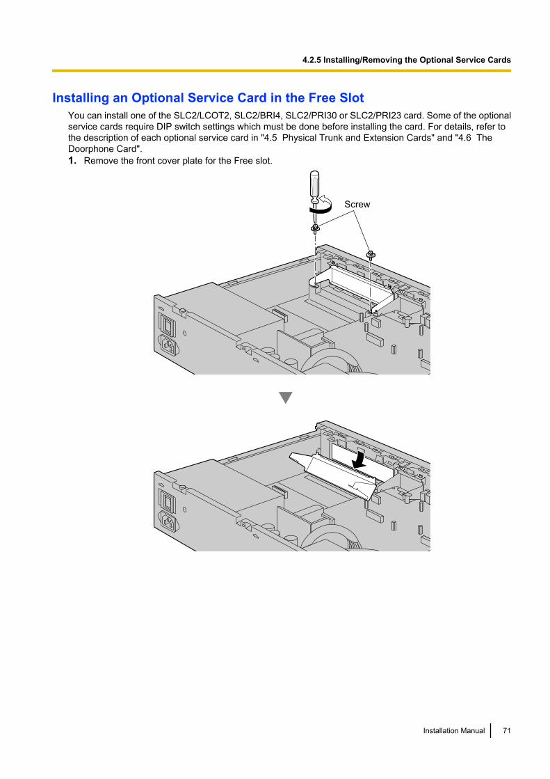
Installing an Optional Service Card in the Free SlotYou can install one of the SLC2/LCOT2, SLC2/BRI4, SLC2/PRI30 or SLC2/PRI23 card. Some of the optionalservice cards require DIP switch settings which must be done before installing the card. For details, refer tothe description of each optional service card in "4.5 Physical Trunk and Extension Cards" and "4.6 TheDoorphone Card".1. Remove the front cover plate for the Free slot.
Screw
Installation Manual 71
4.2.5 Installing/Removing the Optional Service Cards
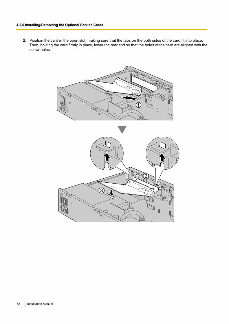
2. Position the card in the open slot, making sure that the tabs on the both sides of the card fit into place.Then, holding the card firmly in place, lower the rear end so that the holes of the card are aligned with thescrew holes.
72 Installation Manual
4.2.5 Installing/Removing the Optional Service Cards
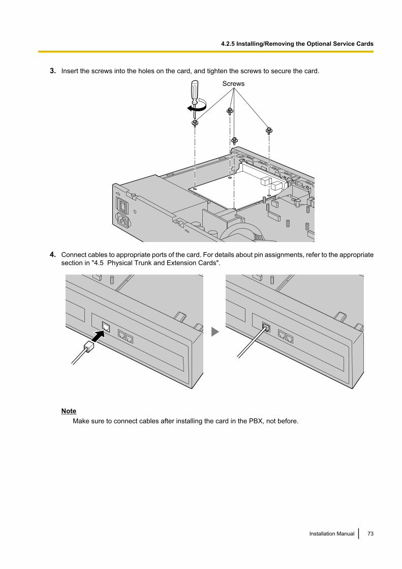
3. Insert the screws into the holes on the card, and tighten the screws to secure the card.
Screws
4. Connect cables to appropriate ports of the card. For details about pin assignments, refer to the appropriatesection in "4.5 Physical Trunk and Extension Cards".
NoteMake sure to connect cables after installing the card in the PBX, not before.
Installation Manual 73
4.2.5 Installing/Removing the Optional Service Cards
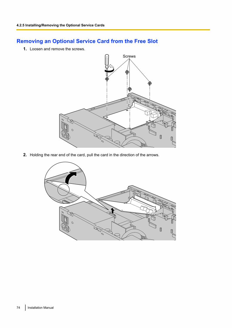
Removing an Optional Service Card from the Free Slot1. Loosen and remove the screws.
Screws
2. Holding the rear end of the card, pull the card in the direction of the arrows.
74 Installation Manual
4.2.5 Installing/Removing the Optional Service Cards
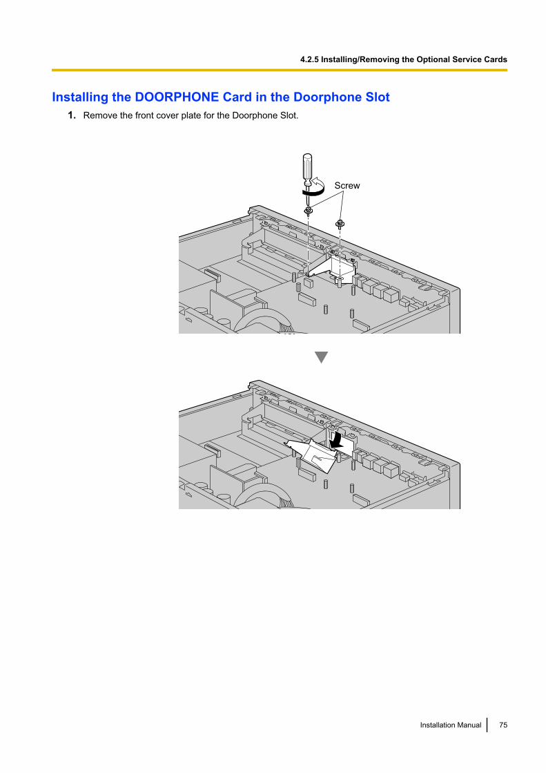
Installing the DOORPHONE Card in the Doorphone Slot1. Remove the front cover plate for the Doorphone Slot.
Screw
Installation Manual 75
4.2.5 Installing/Removing the Optional Service Cards
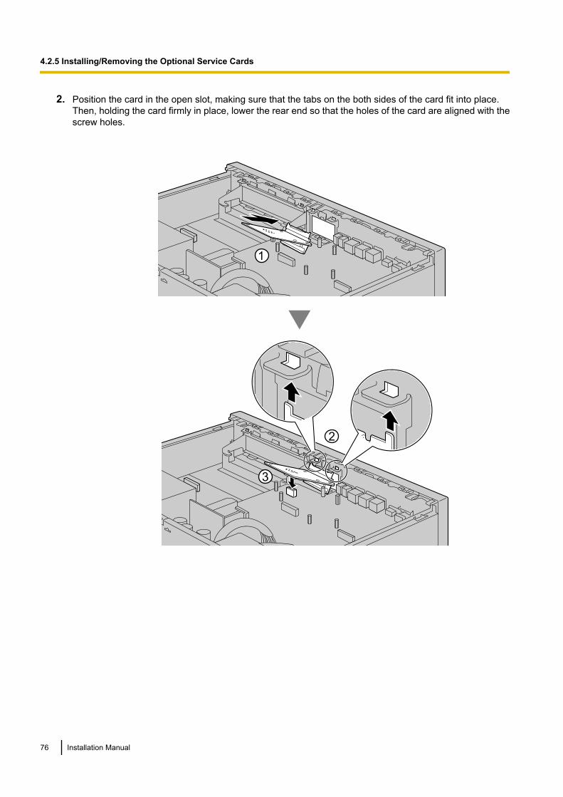
2. Position the card in the open slot, making sure that the tabs on the both sides of the card fit into place.Then, holding the card firmly in place, lower the rear end so that the holes of the card are aligned with thescrew holes.
76 Installation Manual
4.2.5 Installing/Removing the Optional Service Cards
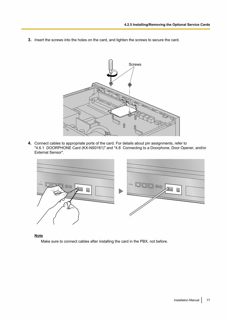
3. Insert the screws into the holes on the card, and tighten the screws to secure the card.
Screws
4. Connect cables to appropriate ports of the card. For details about pin assignments, refer to"4.6.1 DOORPHONE Card (KX-NS0161)" and "4.8 Connecting to a Doorphone, Door Opener, and/orExternal Sensor".
NoteMake sure to connect cables after installing the card in the PBX, not before.
Installation Manual 77
4.2.5 Installing/Removing the Optional Service Cards
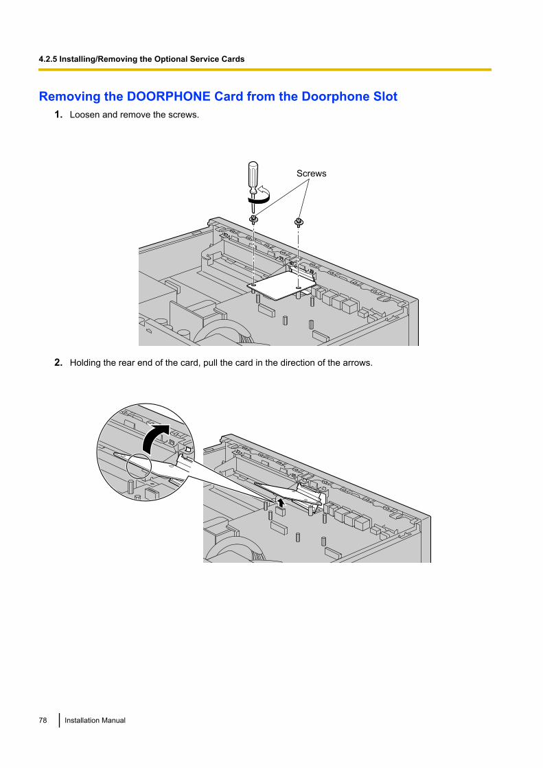
Removing the DOORPHONE Card from the Doorphone Slot1. Loosen and remove the screws.
Screws
2. Holding the rear end of the card, pull the card in the direction of the arrows.
78 Installation Manual
4.2.5 Installing/Removing the Optional Service Cards

4.2.6 Installing/Removing the Storage Memory CardUpgrading from the Initially Installed Storage Memory CardTo increase Voice Mail recording time, you can install an optional Storage Memory Card.For details about optional Storage Memory Cards, refer to "4.3.2 Storage Memory Card (installed by default),Storage Memory S Card (KX-NS0135), Storage Memory M Card (KX-NS0136), Storage Memory L Card(KX-NS0137)".System Prompts
The Storage Memory Card (installed by default) and optional Storage Memory Cards contain systemprompts for Unified Messaging. However, system prompts language data stored in the Storage MemoryCard (installed by default) differ from those found in the optional Storage Memory Cards.For information about the system prompt languages in each Storage Memory Card, refer to "7.7 SystemPrompt Languages".The system prompt language data you are using on the initially installed Storage Memory Card must bebacked up if you want to continue using that Storage Memory Card’s system prompt language data. Afterbacking up the system prompt language data, install the optional Storage Memory Card, and then restorethe backed up system prompt language data to the new Storage Memory Card.This procedure is described below.
1. Complete Easy Setup Wizard after starting the PBX.(For details, refer to "5.4.1 Easy Setup Wizard".)
2. Insert a USB memory device into the USB port of the PBX.(For details, refer to "Using a USB memory device" in "4.9 Connection of Peripherals".)
3. Back up the desired system prompts to the USB memory device.(For details, refer to "6.9 Tool—UM Data Backup" in the PC Programming Manual.)
4. Shut down the PBX, and then turn the power switch off.(For details about shutting down the PBX, refer to "5.5 System Control—System Shutdown" in the PCProgramming Manual.)
5. Remove the Storage Memory Card (installed by default), and then install an optional Storage MemoryCard.(For details, refer to "4.3.2 Storage Memory Card (installed by default), Storage Memory S Card(KX-NS0135), Storage Memory M Card (KX-NS0136), Storage Memory L Card (KX-NS0137)".)
6. Start the PBX as described in "System Initialisation Procedure" in "4.12 Starting the PBX".7. Restore the system prompts backed up in step 3. For details, refer to "6.10 Tool—UM Data Restore" in
the PC Programming Manual.
Before Removing the Storage Memory CardWhen removing the Storage Memory Card after the PBX has been in use, make a backup of the running systemdata so the current data can be restored after installing a new Storage Memory Card. For details about makingbackup files, refer to "7.2.2 Utility—File—File Transfer PBX to PC" in the PC Programming Manual.Backup files cannot be made for some data. For details about which data is not backed up, refer to "SavingModified Data" in the PC Programming Manual. For details about restoring Unified Message data from abackup, refer to "6.10 Tool—UM Data Restore" in the PC Programming Manual.
When you want to back up Unified Messaging system data, a separate backup procedure is required.For details about backing up Unified Messaging data, refer to "6.9 Tool—UM Data Backup" in the PCProgramming Manual.
CAUTION• Before touching the product (PBX, cards, etc.), discharge static electricity by touching ground or
wearing an earthing strap. Failure to do so may cause the PBX to malfunction due to static electricity.• When installing or removing the Storage Memory Card, the power switch must be turned off.• When installing or removing the Storage Memory Card, do not put pressure on any parts of the mother
board. Doing so may result in damage to the PBX.
Installation Manual 79
4.2.6 Installing/Removing the Storage Memory Card

• The Storage Memory Card contains software for all the processes of the PBX and all the customerdata. Therefore, do not allow unauthorised access to prevent data leakage.
• To prevent data leakage, render the Storage Memory Card physically unusable before disposal.
Notice• Use only the Storage Memory Card included with the PBX, or a Panasonic optional upgrade Storage
Memory Card.• The Storage Memory Card must be inserted in the Storage Memory Card slot of the mother board
before startup.
Note• The is shown on the label of your Storage Memory Card to indicate the direction for inserting the
Storage Memory Card.• The maximum length of file names for files that are to be stored in the Storage Memory Card is 60
characters.1. Turn the screw anticlockwise to loosen.
Screw
2. Remove the Storage Memory Card slot cover.
80 Installation Manual
4.2.6 Installing/Removing the Storage Memory Card
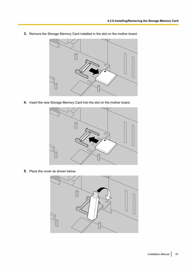
3. Remove the Storage Memory Card installed in the slot on the mother board.
4. Insert the new Storage Memory Card into the slot on the mother board.
5. Place the cover as shown below.
Installation Manual 81
4.2.6 Installing/Removing the Storage Memory Card
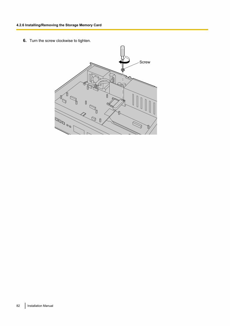
6. Turn the screw clockwise to tighten.
Screw
82 Installation Manual
4.2.6 Installing/Removing the Storage Memory Card
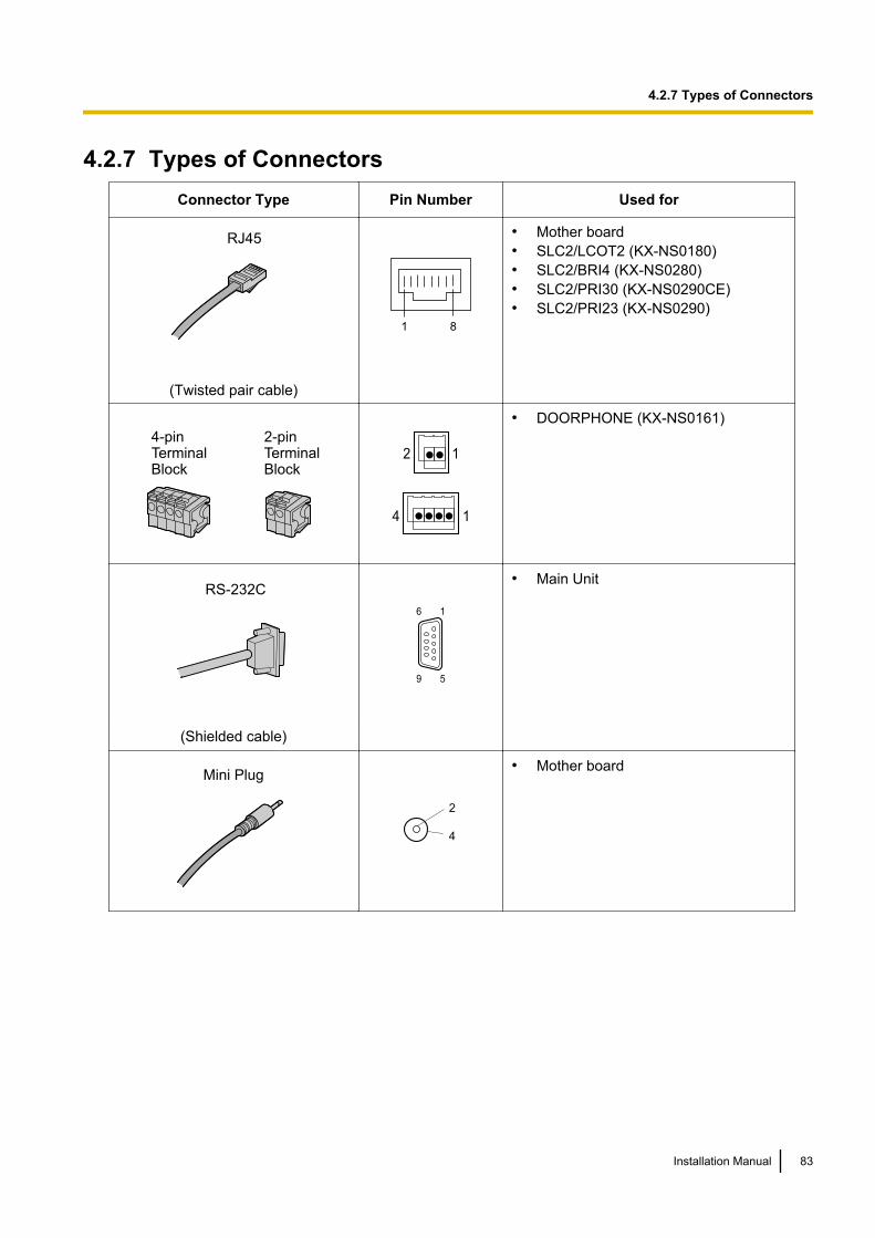
4.2.7 Types of ConnectorsConnector Type Pin Number Used for
RJ45
(Twisted pair cable)
81
• Mother board• SLC2/LCOT2 (KX-NS0180)• SLC2/BRI4 (KX-NS0280)• SLC2/PRI30 (KX-NS0290CE)• SLC2/PRI23 (KX-NS0290)
4-pinTerminalBlock
2-pinTerminalBlock
2 1
4 1
• DOORPHONE (KX-NS0161)
RS-232C
9 5
6 1
• Main Unit
(Shielded cable)
Mini Plug
2
4
• Mother board
Installation Manual 83
4.2.7 Types of Connectors
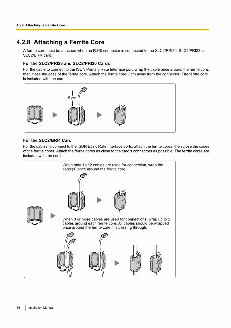
4.2.8 Attaching a Ferrite CoreA ferrite core must be attached when an RJ45 connector is connected to the SLC2/PRI30, SLC2/PRI23 orSLC2/BRI4 card.
For the SLC2/PRI23 and SLC2/PRI30 CardsFor the cable to connect to the ISDN Primary Rate Interface port, wrap the cable once around the ferrite core,then close the case of the ferrite core. Attach the ferrite core 5 cm away from the connector. The ferrite coreis included with the card.
5 cm
For the SLC2/BRI4 CardFor the cables to connect to the ISDN Basic Rate Interface ports, attach the ferrite cores, then close the casesof the ferrite cores. Attach the ferrite cores as close to the card’s connectors as possible. The ferrite cores areincluded with the card.
When only 1 or 2 cables are used for connection, wrap the cable(s) once around the ferrite core.
When 3 or more cables are used for connections, wrap up to 2 cables around each ferrite core. All cables should be wrapped once around the ferrite core it is passing through.
84 Installation Manual
4.2.8 Attaching a Ferrite Core
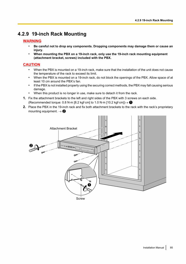
4.2.9 19-inch Rack MountingWARNING
• Be careful not to drop any components. Dropping components may damage them or cause aninjury.
• When mounting the PBX on a 19-inch rack, only use the 19-inch rack mounting equipment(attachment bracket, screws) included with the PBX.
CAUTION• When the PBX is mounted on a 19-inch rack, make sure that the installation of the unit does not cause
the temperature of the rack to exceed its limit.• When the PBX is mounted on a 19-inch rack, do not block the openings of the PBX. Allow space of at
least 10 cm around the PBX’s fan.• If the PBX is not installed properly using the securing correct methods, the PBX may fall causing serious
damage.• When this product is no longer in use, make sure to detach it from the rack.
1. Fix the attachment brackets to the left and right sides of the PBX with 3 screws on each side.(Recommended torque: 0.8 N·m [8.2 kgf·cm] to 1.0 N·m [10.2 kgf·cm])® 1
2. Place the PBX in the 19-inch rack and fix both attachment brackets to the rack with the rack’s proprietarymounting equipment. ® 2
1
2
Screw
Attachment Bracket
Installation Manual 85
4.2.9 19-inch Rack Mounting
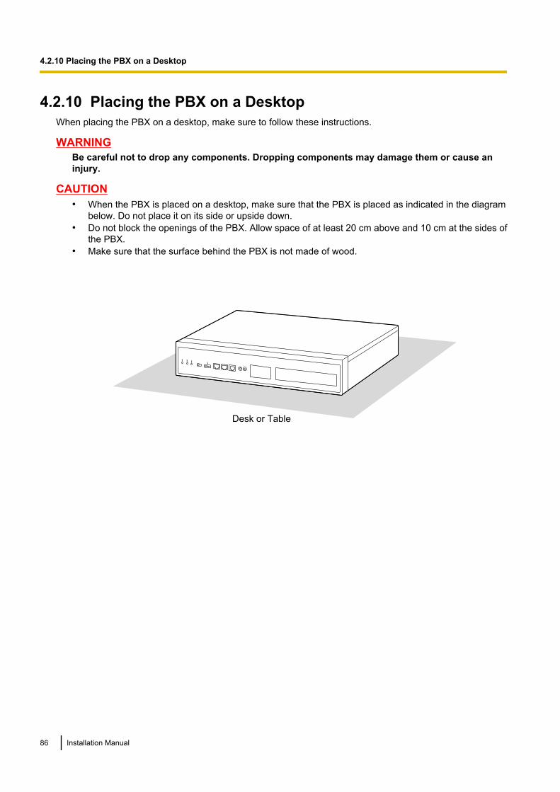
4.2.10 Placing the PBX on a DesktopWhen placing the PBX on a desktop, make sure to follow these instructions.
WARNINGBe careful not to drop any components. Dropping components may damage them or cause aninjury.
CAUTION• When the PBX is placed on a desktop, make sure that the PBX is placed as indicated in the diagram
below. Do not place it on its side or upside down.• Do not block the openings of the PBX. Allow space of at least 20 cm above and 10 cm at the sides of
the PBX.• Make sure that the surface behind the PBX is not made of wood.
Desk or Table
86 Installation Manual
4.2.10 Placing the PBX on a Desktop
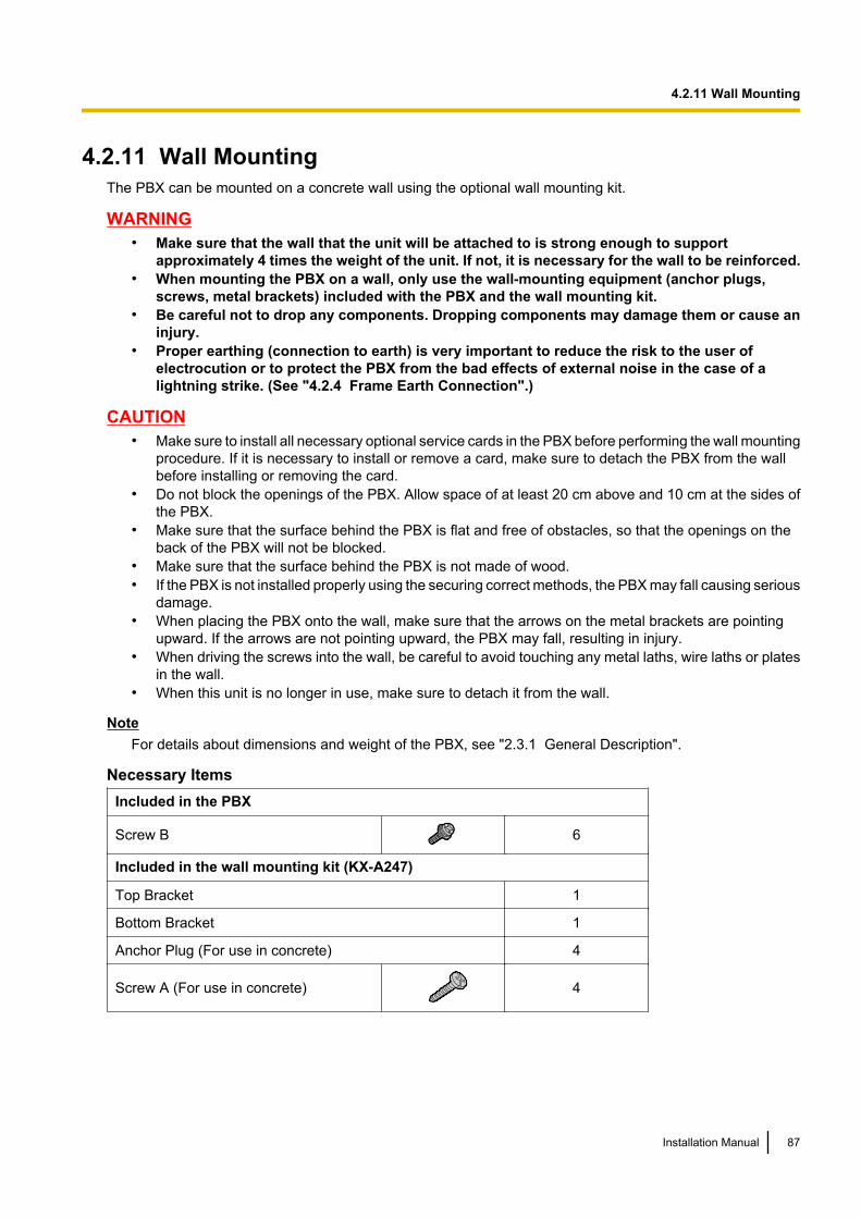
4.2.11 Wall MountingThe PBX can be mounted on a concrete wall using the optional wall mounting kit.
WARNING• Make sure that the wall that the unit will be attached to is strong enough to support
approximately 4 times the weight of the unit. If not, it is necessary for the wall to be reinforced.• When mounting the PBX on a wall, only use the wall-mounting equipment (anchor plugs,
screws, metal brackets) included with the PBX and the wall mounting kit.• Be careful not to drop any components. Dropping components may damage them or cause an
injury.• Proper earthing (connection to earth) is very important to reduce the risk to the user of
electrocution or to protect the PBX from the bad effects of external noise in the case of alightning strike. (See "4.2.4 Frame Earth Connection".)
CAUTION• Make sure to install all necessary optional service cards in the PBX before performing the wall mounting
procedure. If it is necessary to install or remove a card, make sure to detach the PBX from the wallbefore installing or removing the card.
• Do not block the openings of the PBX. Allow space of at least 20 cm above and 10 cm at the sides ofthe PBX.
• Make sure that the surface behind the PBX is flat and free of obstacles, so that the openings on theback of the PBX will not be blocked.
• Make sure that the surface behind the PBX is not made of wood.• If the PBX is not installed properly using the securing correct methods, the PBX may fall causing serious
damage.• When placing the PBX onto the wall, make sure that the arrows on the metal brackets are pointing
upward. If the arrows are not pointing upward, the PBX may fall, resulting in injury.• When driving the screws into the wall, be careful to avoid touching any metal laths, wire laths or plates
in the wall.• When this unit is no longer in use, make sure to detach it from the wall.
NoteFor details about dimensions and weight of the PBX, see "2.3.1 General Description".
Necessary ItemsIncluded in the PBX
Screw B 6
Included in the wall mounting kit (KX-A247)
Top Bracket 1
Bottom Bracket 1
Anchor Plug (For use in concrete) 4
Screw A (For use in concrete) 4
Installation Manual 87
4.2.11 Wall Mounting
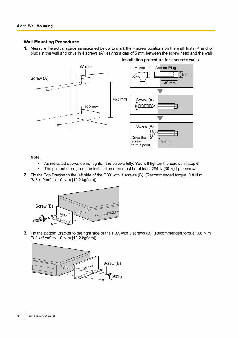
Wall Mounting Procedures1. Measure the actual space as indicated below to mark the 4 screw positions on the wall. Install 4 anchor
plugs in the wall and drive in 4 screws (A) leaving a gap of 5 mm between the screw head and the wall.
Screw (A)30 mm
8 mm
5 mm
Screw (A)
Screw (A)
Hammer Anchor Plug
Drive the screw to this point.
463 mm
87 mm
192 mm
Installation procedure for concrete walls.
Note• As indicated above, do not tighten the screws fully. You will tighten the screws in step 6.• The pull-out strength of the installation area must be at least 294 N (30 kgf) per screw.
2. Fix the Top Bracket to the left side of the PBX with 3 screws (B). (Recommended torque: 0.8 N·m[8.2 kgf·cm] to 1.0 N·m [10.2 kgf·cm])
Screw (B)
3. Fix the Bottom Bracket to the right side of the PBX with 3 screws (B). (Recommended torque: 0.8 N·m[8.2 kgf·cm] to 1.0 N·m [10.2 kgf·cm])
Screw (B)
88 Installation Manual
4.2.11 Wall Mounting
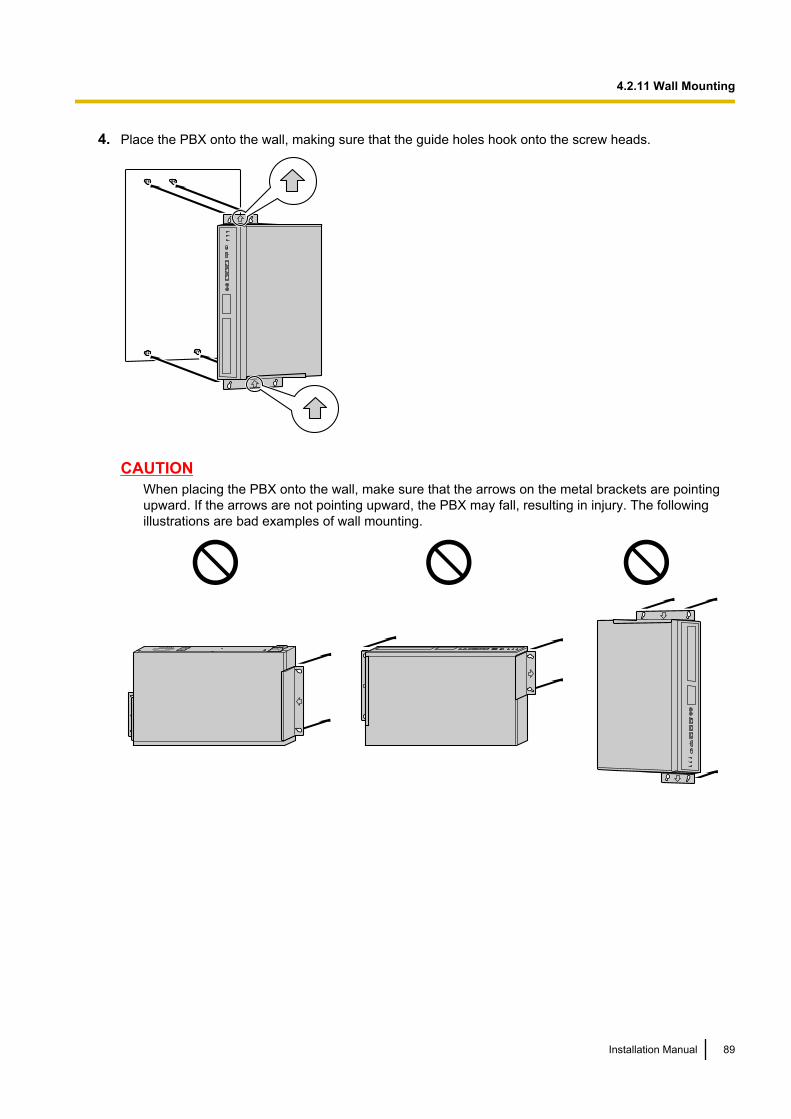
4. Place the PBX onto the wall, making sure that the guide holes hook onto the screw heads.
CAUTIONWhen placing the PBX onto the wall, make sure that the arrows on the metal brackets are pointingupward. If the arrows are not pointing upward, the PBX may fall, resulting in injury. The followingillustrations are bad examples of wall mounting.
Installation Manual 89
4.2.11 Wall Mounting
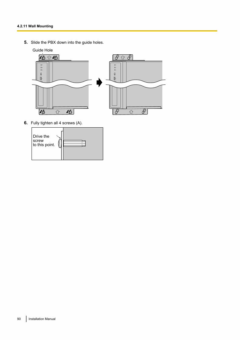
5. Slide the PBX down into the guide holes.
Guide Hole
6. Fully tighten all 4 screws (A).
Drive the screw to this point.
90 Installation Manual
4.2.11 Wall Mounting
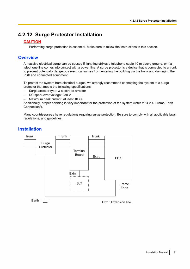
4.2.12 Surge Protector InstallationCAUTION
Performing surge protection is essential. Make sure to follow the instructions in this section.
OverviewA massive electrical surge can be caused if lightning strikes a telephone cable 10 m above ground, or if atelephone line comes into contact with a power line. A surge protector is a device that is connected to a trunkto prevent potentially dangerous electrical surges from entering the building via the trunk and damaging thePBX and connected equipment.
To protect the system from electrical surges, we strongly recommend connecting the system to a surgeprotector that meets the following specifications:– Surge arrestor type: 3-electrode arrestor– DC spark-over voltage: 230 V– Maximum peak current: at least 10 kAAdditionally, proper earthing is very important for the protection of the system (refer to "4.2.4 Frame EarthConnection").
Many countries/areas have regulations requiring surge protection. Be sure to comply with all applicable laws,regulations, and guidelines.
InstallationTrunk TrunkTrunk
Earth
Surge
Protector
Extn.
Extn.
Extn.: Extension line
SLT
PBX
Frame
Earth
Terminal
Board
Installation Manual 91
4.2.12 Surge Protector Installation

Outside Installation
Trunk
Extn.
Trunk
Surge Protector
Terminal
BoardSurge
Protector
PBX
(Main Building)
Extn.: Extension Line
Extn.
Extn.
Earth
Extn.
SLT
(Another Building)
SLT
If you install an extension outside of the building, the following precautions are recommended:a. Install the extension wire underground.b. Use a conduit to protect the wire.
NoteThe surge protector for an extension is different from that for trunks.
Installation of an Earth Rod
Trunk
PBX
Earth Rod
(Underground)
Surge Protector
Earthing
Wire
92 Installation Manual
4.2.12 Surge Protector Installation

1. Connect the earth rod to the surge protector using an earthing wire with a cross-sectional area of at least1.3 mm2.
2. Bury the earth rod near the protector. The earthing wire should be as short as possible.3. The earthing wire should run straight to the earth rod. Do not run the wire around other objects.4. Bury the earth rod at least 50 cm underground.
Note• The above figures are recommendations only.• The length of earth rod and the required depth depend on the composition of the soil.
Installation Manual 93
4.2.12 Surge Protector Installation
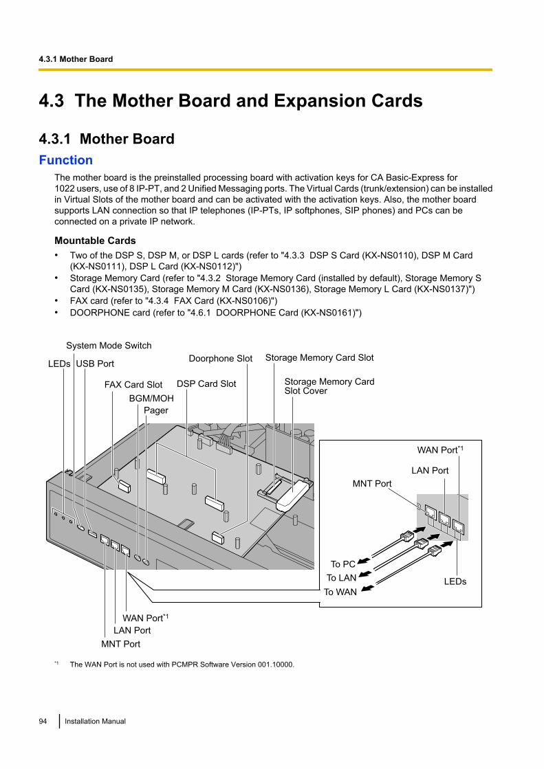
4.3 The Mother Board and Expansion Cards
4.3.1 Mother BoardFunction
The mother board is the preinstalled processing board with activation keys for CA Basic-Express for1022 users, use of 8 IP-PT, and 2 Unified Messaging ports. The Virtual Cards (trunk/extension) can be installedin Virtual Slots of the mother board and can be activated with the activation keys. Also, the mother boardsupports LAN connection so that IP telephones (IP-PTs, IP softphones, SIP phones) and PCs can beconnected on a private IP network.
Mountable Cards• Two of the DSP S, DSP M, or DSP L cards (refer to "4.3.3 DSP S Card (KX-NS0110), DSP M Card
(KX-NS0111), DSP L Card (KX-NS0112)")• Storage Memory Card (refer to "4.3.2 Storage Memory Card (installed by default), Storage Memory S
Card (KX-NS0135), Storage Memory M Card (KX-NS0136), Storage Memory L Card (KX-NS0137)")• FAX card (refer to "4.3.4 FAX Card (KX-NS0106)")• DOORPHONE card (refer to "4.6.1 DOORPHONE Card (KX-NS0161)")
LEDs
Storage Memory Card Slot Cover
Storage Memory Card Slot
DSP Card Slot
BGM/MOH
Pager
MNT Port
LAN Port
To LAN
To PC
USB Port
LAN Port
WAN Port*1
LEDs
System Mode Switch
MNT Port
FAX Card Slot
To WAN
WAN Port*1
Doorphone Slot
*1 The WAN Port is not used with PCMPR Software Version 001.10000.
94 Installation Manual
4.3.1 Mother Board
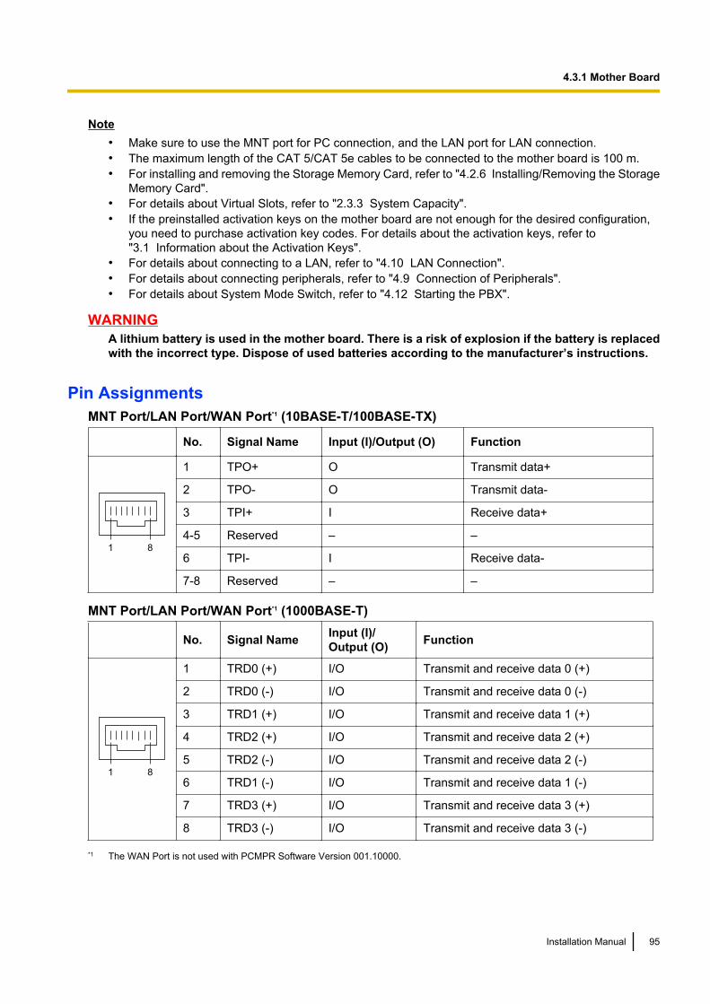
Note• Make sure to use the MNT port for PC connection, and the LAN port for LAN connection.• The maximum length of the CAT 5/CAT 5e cables to be connected to the mother board is 100 m.• For installing and removing the Storage Memory Card, refer to "4.2.6 Installing/Removing the Storage
Memory Card".• For details about Virtual Slots, refer to "2.3.3 System Capacity".• If the preinstalled activation keys on the mother board are not enough for the desired configuration,
you need to purchase activation key codes. For details about the activation keys, refer to"3.1 Information about the Activation Keys".
• For details about connecting to a LAN, refer to "4.10 LAN Connection".• For details about connecting peripherals, refer to "4.9 Connection of Peripherals".• For details about System Mode Switch, refer to "4.12 Starting the PBX".
WARNINGA lithium battery is used in the mother board. There is a risk of explosion if the battery is replacedwith the incorrect type. Dispose of used batteries according to the manufacturer’s instructions.
Pin AssignmentsMNT Port/LAN Port/WAN Port*1 (10BASE-T/100BASE-TX)
No. Signal Name Input (I)/Output (O) Function
81
1 TPO+ O Transmit data+
2 TPO- O Transmit data-
3 TPI+ I Receive data+
4-5 Reserved – –
6 TPI- I Receive data-
7-8 Reserved – –
MNT Port/LAN Port/WAN Port*1 (1000BASE-T)
No. Signal Name Input (I)/Output (O) Function
81
1 TRD0 (+) I/O Transmit and receive data 0 (+)
2 TRD0 (-) I/O Transmit and receive data 0 (-)
3 TRD1 (+) I/O Transmit and receive data 1 (+)
4 TRD2 (+) I/O Transmit and receive data 2 (+)
5 TRD2 (-) I/O Transmit and receive data 2 (-)
6 TRD1 (-) I/O Transmit and receive data 1 (-)
7 TRD3 (+) I/O Transmit and receive data 3 (+)
8 TRD3 (-) I/O Transmit and receive data 3 (-)
*1 The WAN Port is not used with PCMPR Software Version 001.10000.
Installation Manual 95
4.3.1 Mother Board
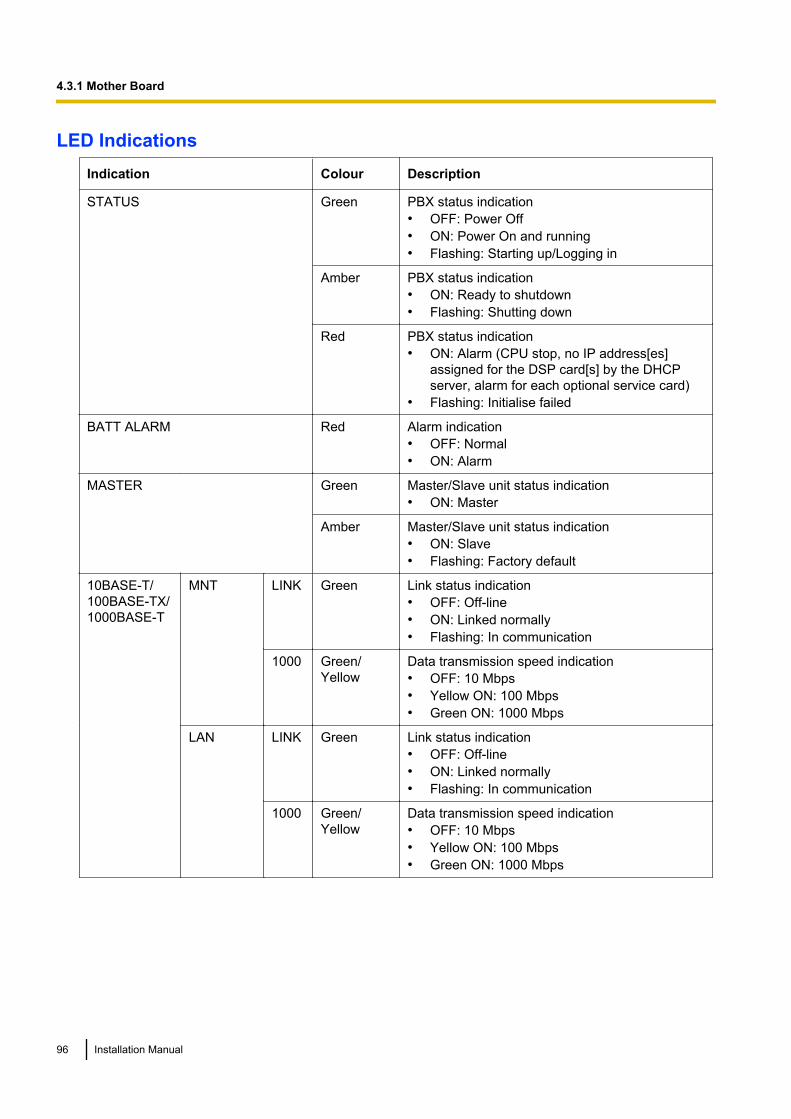
LED IndicationsIndication Colour Description
STATUS Green PBX status indication• OFF: Power Off• ON: Power On and running• Flashing: Starting up/Logging in
Amber PBX status indication• ON: Ready to shutdown• Flashing: Shutting down
Red PBX status indication• ON: Alarm (CPU stop, no IP address[es]
assigned for the DSP card[s] by the DHCPserver, alarm for each optional service card)
• Flashing: Initialise failed
BATT ALARM Red Alarm indication• OFF: Normal• ON: Alarm
MASTER Green Master/Slave unit status indication• ON: Master
Amber Master/Slave unit status indication• ON: Slave• Flashing: Factory default
10BASE-T/100BASE-TX/1000BASE-T
MNT LINK Green Link status indication• OFF: Off-line• ON: Linked normally• Flashing: In communication
1000 Green/Yellow
Data transmission speed indication• OFF: 10 Mbps• Yellow ON: 100 Mbps• Green ON: 1000 Mbps
LAN LINK Green Link status indication• OFF: Off-line• ON: Linked normally• Flashing: In communication
1000 Green/Yellow
Data transmission speed indication• OFF: 10 Mbps• Yellow ON: 100 Mbps• Green ON: 1000 Mbps
96 Installation Manual
4.3.1 Mother Board
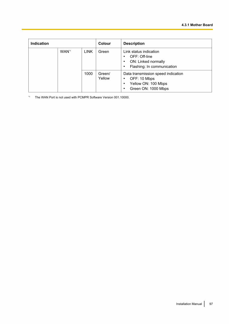
Indication Colour Description
WAN*1 LINK Green Link status indication• OFF: Off-line• ON: Linked normally• Flashing: In communication
1000 Green/Yellow
Data transmission speed indication• OFF: 10 Mbps• Yellow ON: 100 Mbps• Green ON: 1000 Mbps
*1 The WAN Port is not used with PCMPR Software Version 001.10000.
Installation Manual 97
4.3.1 Mother Board
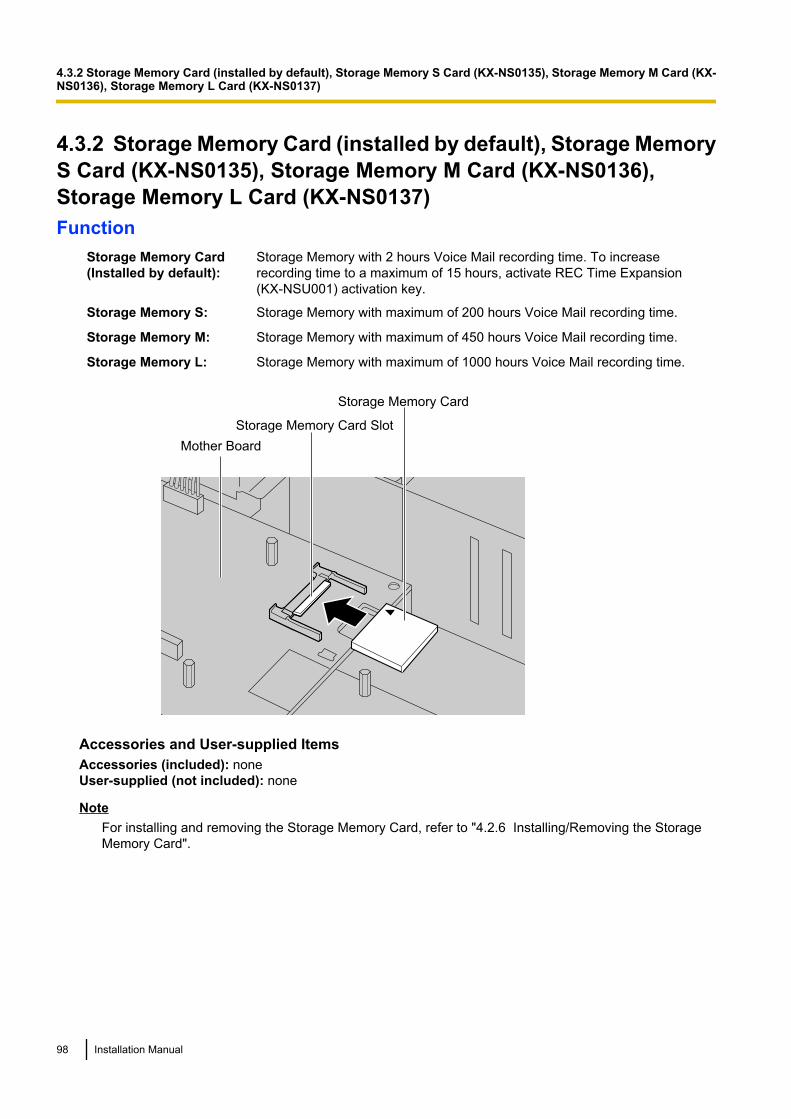
4.3.2 Storage Memory Card (installed by default), Storage MemoryS Card (KX-NS0135), Storage Memory M Card (KX-NS0136),Storage Memory L Card (KX-NS0137)Function
Storage Memory Card(Installed by default):
Storage Memory with 2 hours Voice Mail recording time. To increaserecording time to a maximum of 15 hours, activate REC Time Expansion(KX-NSU001) activation key.
Storage Memory S: Storage Memory with maximum of 200 hours Voice Mail recording time.
Storage Memory M: Storage Memory with maximum of 450 hours Voice Mail recording time.
Storage Memory L: Storage Memory with maximum of 1000 hours Voice Mail recording time.
Storage Memory Card
Storage Memory Card Slot
Mother Board
Accessories and User-supplied ItemsAccessories (included): noneUser-supplied (not included): none
NoteFor installing and removing the Storage Memory Card, refer to "4.2.6 Installing/Removing the StorageMemory Card".
98 Installation Manual
4.3.2 Storage Memory Card (installed by default), Storage Memory S Card (KX-NS0135), Storage Memory M Card (KX-NS0136), Storage Memory L Card (KX-NS0137)
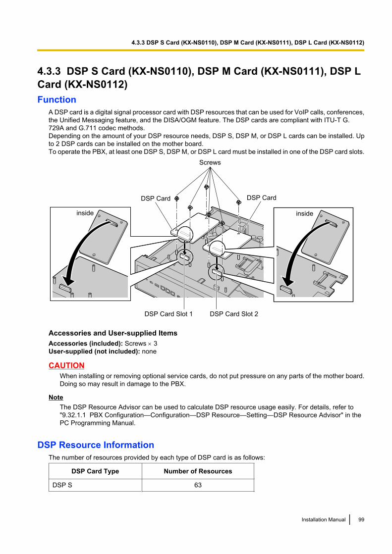
4.3.3 DSP S Card (KX-NS0110), DSP M Card (KX-NS0111), DSP LCard (KX-NS0112)Function
A DSP card is a digital signal processor card with DSP resources that can be used for VoIP calls, conferences,the Unified Messaging feature, and the DISA/OGM feature. The DSP cards are compliant with ITU-T G.729A and G.711 codec methods.Depending on the amount of your DSP resource needs, DSP S, DSP M, or DSP L cards can be installed. Upto 2 DSP cards can be installed on the mother board.To operate the PBX, at least one DSP S, DSP M, or DSP L card must be installed in one of the DSP card slots.
inside
DSP Card
Screws
DSP Card
inside
DSP Card Slot 2DSP Card Slot 1
Accessories and User-supplied ItemsAccessories (included): Screws ´ 3User-supplied (not included): none
CAUTIONWhen installing or removing optional service cards, do not put pressure on any parts of the mother board.Doing so may result in damage to the PBX.
NoteThe DSP Resource Advisor can be used to calculate DSP resource usage easily. For details, refer to"9.32.1.1 PBX Configuration—Configuration—DSP Resource—Setting—DSP Resource Advisor" in thePC Programming Manual.
DSP Resource InformationThe number of resources provided by each type of DSP card is as follows:
DSP Card Type Number of Resources
DSP S 63
Installation Manual 99
4.3.3 DSP S Card (KX-NS0110), DSP M Card (KX-NS0111), DSP L Card (KX-NS0112)

DSP Card Type Number of Resources
DSP M 127
DSP L 254
IP Address InformationEither 1 or 2 IP addresses must be assigned to each DSP card, depending on the type of DSP card. You canassign IP addresses to the DSP cards during Easy Setup Wizard or through system programming.For details about Easy Setup Wizard, refer to "5.4.1 Easy Setup Wizard".For details about assigning IP addresses through System Programming, refer to "Changing IP AddressSettings".
DSP Card Type Number of IP Addresses
DSP S/DSP M 1
DSP L 2
100 Installation Manual
4.3.3 DSP S Card (KX-NS0110), DSP M Card (KX-NS0111), DSP L Card (KX-NS0112)
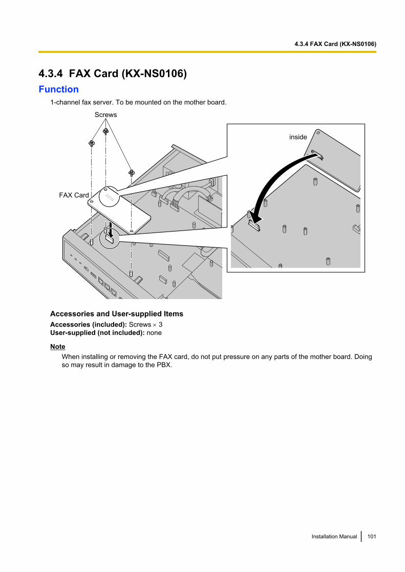
4.3.4 FAX Card (KX-NS0106)Function
1-channel fax server. To be mounted on the mother board.
FAX Card
Screws
inside
Accessories and User-supplied ItemsAccessories (included): Screws ´ 3User-supplied (not included): none
NoteWhen installing or removing the FAX card, do not put pressure on any parts of the mother board. Doingso may result in damage to the PBX.
Installation Manual 101
4.3.4 FAX Card (KX-NS0106)
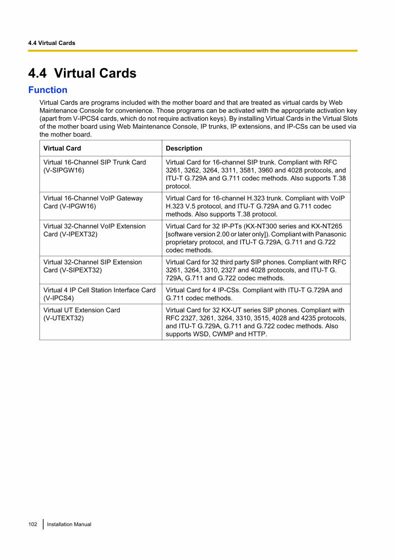
4.4 Virtual CardsFunction
Virtual Cards are programs included with the mother board and that are treated as virtual cards by WebMaintenance Console for convenience. Those programs can be activated with the appropriate activation key(apart from V-IPCS4 cards, which do not require activation keys). By installing Virtual Cards in the Virtual Slotsof the mother board using Web Maintenance Console, IP trunks, IP extensions, and IP-CSs can be used viathe mother board.
Virtual Card Description
Virtual 16-Channel SIP Trunk Card(V-SIPGW16)
Virtual Card for 16-channel SIP trunk. Compliant with RFC3261, 3262, 3264, 3311, 3581, 3960 and 4028 protocols, andITU-T G.729A and G.711 codec methods. Also supports T.38protocol.
Virtual 16-Channel VoIP GatewayCard (V-IPGW16)
Virtual Card for 16-channel H.323 trunk. Compliant with VoIPH.323 V.5 protocol, and ITU-T G.729A and G.711 codecmethods. Also supports T.38 protocol.
Virtual 32-Channel VoIP ExtensionCard (V-IPEXT32)
Virtual Card for 32 IP-PTs (KX-NT300 series and KX-NT265[software version 2.00 or later only]). Compliant with Panasonicproprietary protocol, and ITU-T G.729A, G.711 and G.722codec methods.
Virtual 32-Channel SIP ExtensionCard (V-SIPEXT32)
Virtual Card for 32 third party SIP phones. Compliant with RFC3261, 3264, 3310, 2327 and 4028 protocols, and ITU-T G.729A, G.711 and G.722 codec methods.
Virtual 4 IP Cell Station Interface Card(V-IPCS4)
Virtual Card for 4 IP-CSs. Compliant with ITU-T G.729A andG.711 codec methods.
Virtual UT Extension Card(V-UTEXT32)
Virtual Card for 32 KX-UT series SIP phones. Compliant withRFC 2327, 3261, 3264, 3310, 3515, 4028 and 4235 protocols,and ITU-T G.729A, G.711 and G.722 codec methods. Alsosupports WSD, CWMP and HTTP.
102 Installation Manual
4.4 Virtual Cards
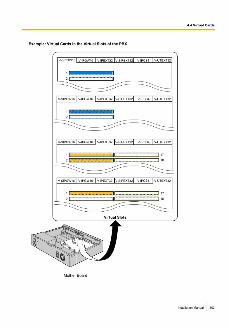
Example: Virtual Cards in the Virtual Slots of the PBX
Mother Board
V-IPGW16 V-IPEXT32 V-SIPEXT32 V-IPCS4 V-UTEXT32
1
2
V-SIPGW16
V-IPEXT32 V-SIPEXT32 V-IPCS4 V-UTEXT32V-IPGW16
1
2
V-SIPGW16
V-IPGW16 V-SIPEXT32 V-IPCS4 V-UTEXT32V-IPEXT32
1
2
V-SIPGW16
17
18
V-IPGW16 V-UTEXT32
1
2
V-SIPGW16
17
18
V-IPEXT32 V-SIPEXT32 V-IPCS4
Virtual Slots
Installation Manual 103
4.4 Virtual Cards
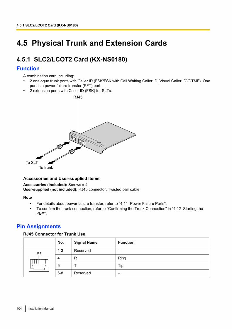
4.5 Physical Trunk and Extension Cards
4.5.1 SLC2/LCOT2 Card (KX-NS0180)Function
A combination card including:• 2 analogue trunk ports with Caller ID (FSK/FSK with Call Waiting Caller ID [Visual Caller ID]/DTMF). One
port is a power failure transfer (PFT) port.• 2 extension ports with Caller ID (FSK) for SLTs.
To trunk
To SLT
RJ45
Accessories and User-supplied ItemsAccessories (included): Screws ´ 4User-supplied (not included): RJ45 connector, Twisted pair cable
Note• For details about power failure transfer, refer to "4.11 Power Failure Ports".• To confirm the trunk connection, refer to "Confirming the Trunk Connection" in "4.12 Starting the
PBX".
Pin AssignmentsRJ45 Connector for Trunk Use
No. Signal Name Function
1 8
R T1-3 Reserved –
4 R Ring
5 T Tip
6-8 Reserved –
104 Installation Manual
4.5.1 SLC2/LCOT2 Card (KX-NS0180)
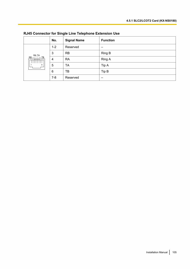
RJ45 Connector for Single Line Telephone Extension Use
No. Signal Name Function
1 8
RA TARB TB
1-2 Reserved –
3 RB Ring B
4 RA Ring A
5 TA Tip A
6 TB Tip B
7-8 Reserved –
Installation Manual 105
4.5.1 SLC2/LCOT2 Card (KX-NS0180)
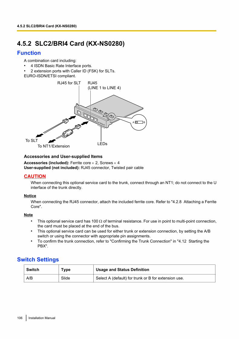
4.5.2 SLC2/BRI4 Card (KX-NS0280)Function
A combination card including:• 4 ISDN Basic Rate Interface ports.• 2 extension ports with Caller ID (FSK) for SLTs.EURO-ISDN/ETSI compliant.
A B
LEDsTo NT1/ Extension
To SLT
RJ45
(LINE 1 to LINE 4)
RJ45 for SLT
Accessories and User-supplied ItemsAccessories (included): Ferrite core ´ 2, Screws ´ 4User-supplied (not included): RJ45 connector, Twisted pair cable
CAUTIONWhen connecting this optional service card to the trunk, connect through an NT1; do not connect to the Uinterface of the trunk directly.
NoticeWhen connecting the RJ45 connector, attach the included ferrite core. Refer to "4.2.8 Attaching a FerriteCore".
Note• This optional service card has 100 W of terminal resistance. For use in point to multi-point connection,
the card must be placed at the end of the bus.• This optional service card can be used for either trunk or extension connection, by setting the A/B
switch or using the connector with appropriate pin assignments.• To confirm the trunk connection, refer to "Confirming the Trunk Connection" in "4.12 Starting the
PBX".
Switch SettingsSwitch Type Usage and Status Definition
A/B Slide Select A (default) for trunk or B for extension use.
106 Installation Manual
4.5.2 SLC2/BRI4 Card (KX-NS0280)
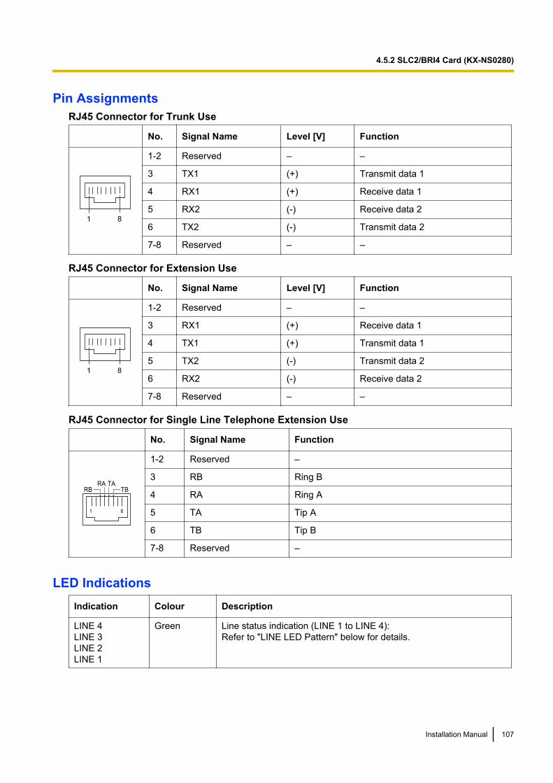
Pin AssignmentsRJ45 Connector for Trunk Use
No. Signal Name Level [V] Function
81
1-2 Reserved – –
3 TX1 (+) Transmit data 1
4 RX1 (+) Receive data 1
5 RX2 (-) Receive data 2
6 TX2 (-) Transmit data 2
7-8 Reserved – –
RJ45 Connector for Extension Use
No. Signal Name Level [V] Function
81
1-2 Reserved – –
3 RX1 (+) Receive data 1
4 TX1 (+) Transmit data 1
5 TX2 (-) Transmit data 2
6 RX2 (-) Receive data 2
7-8 Reserved – –
RJ45 Connector for Single Line Telephone Extension Use
No. Signal Name Function
1 8
RA TARB TB
1-2 Reserved –
3 RB Ring B
4 RA Ring A
5 TA Tip A
6 TB Tip B
7-8 Reserved –
LED IndicationsIndication Colour Description
LINE 4LINE 3LINE 2LINE 1
Green Line status indication (LINE 1 to LINE 4):Refer to "LINE LED Pattern" below for details.
Installation Manual 107
4.5.2 SLC2/BRI4 Card (KX-NS0280)
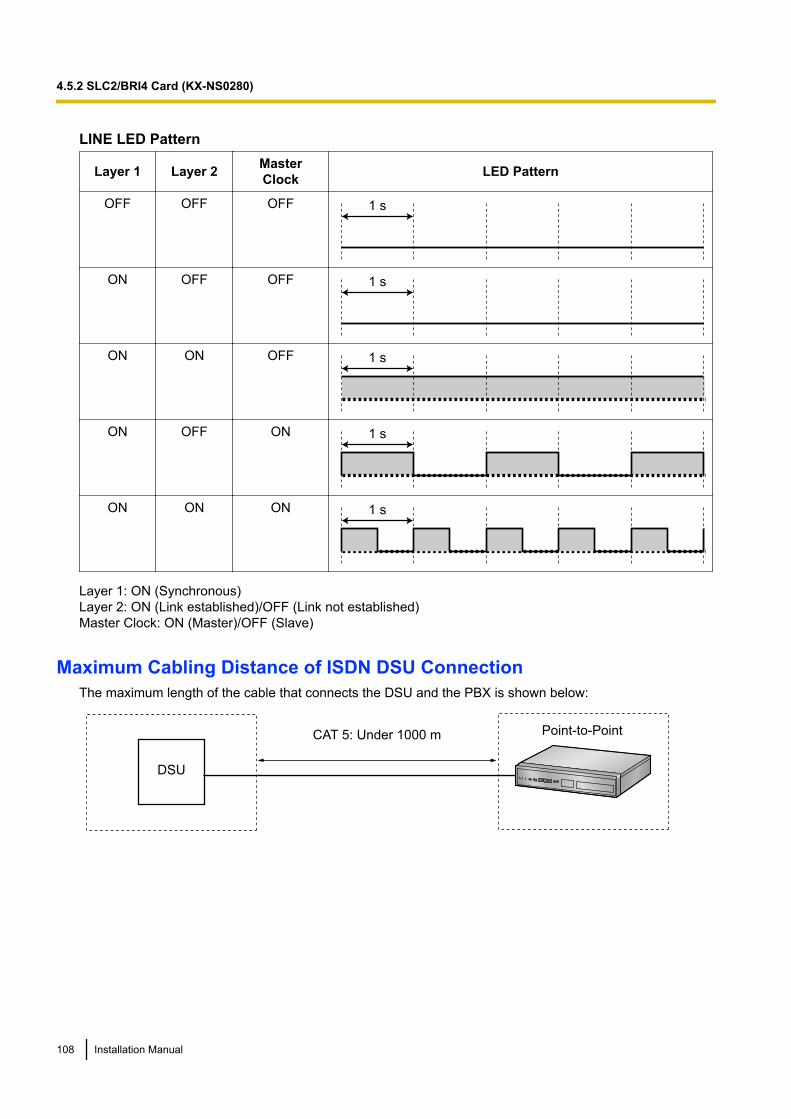
LINE LED Pattern
Layer 1 Layer 2 MasterClock LED Pattern
OFF OFF OFF 1 s
ON OFF OFF 1 s
ON ON OFF 1 s
ON OFF ON 1 s
ON ON ON 1 s
Layer 1: ON (Synchronous)Layer 2: ON (Link established)/OFF (Link not established)Master Clock: ON (Master)/OFF (Slave)
Maximum Cabling Distance of ISDN DSU ConnectionThe maximum length of the cable that connects the DSU and the PBX is shown below:
CAT 5: Under 1000 m
DSU
Point-to-Point
108 Installation Manual
4.5.2 SLC2/BRI4 Card (KX-NS0280)
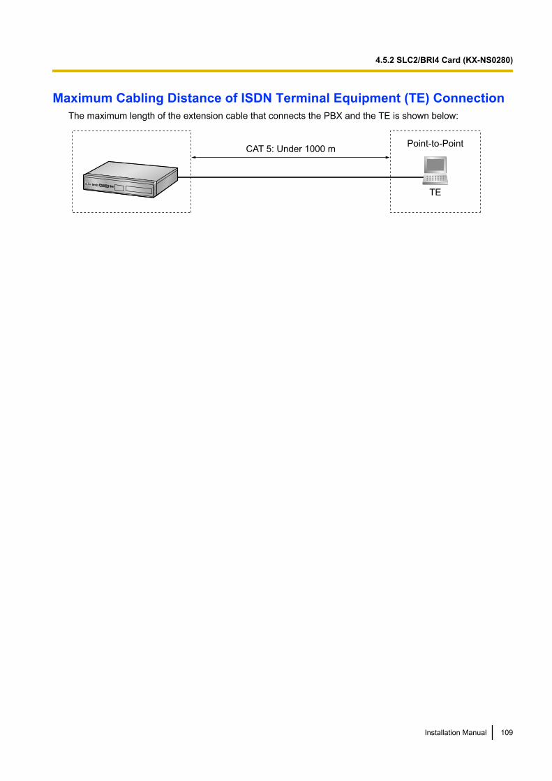
Maximum Cabling Distance of ISDN Terminal Equipment (TE) ConnectionThe maximum length of the extension cable that connects the PBX and the TE is shown below:
CAT 5: Under 1000 m
TE
Point-to-Point
Installation Manual 109
4.5.2 SLC2/BRI4 Card (KX-NS0280)
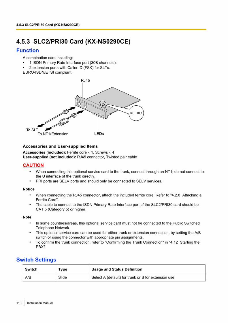
4.5.3 SLC2/PRI30 Card (KX-NS0290CE)Function
A combination card including:• 1 ISDN Primary Rate Interface port (30B channels).• 2 extension ports with Caller ID (FSK) for SLTs.EURO-ISDN/ETSI compliant.
LEDsTo NT1/ ExtensionTo SLT
LEDs
B A
RJ45
Accessories and User-supplied ItemsAccessories (included): Ferrite core ´ 1, Screws ´ 4User-supplied (not included): RJ45 connector, Twisted pair cable
CAUTION• When connecting this optional service card to the trunk, connect through an NT1; do not connect to
the U interface of the trunk directly.• PRI ports are SELV ports and should only be connected to SELV services.
Notice• When connecting the RJ45 connector, attach the included ferrite core. Refer to "4.2.8 Attaching a
Ferrite Core".• The cable to connect to the ISDN Primary Rate Interface port of the SLC2/PRI30 card should be
CAT 5 (Category 5) or higher.
Note• In some countries/areas, this optional service card must not be connected to the Public Switched
Telephone Network.• This optional service card can be used for either trunk or extension connection, by setting the A/B
switch or using the connector with appropriate pin assignments.• To confirm the trunk connection, refer to "Confirming the Trunk Connection" in "4.12 Starting the
PBX".
Switch SettingsSwitch Type Usage and Status Definition
A/B Slide Select A (default) for trunk or B for extension use.
110 Installation Manual
4.5.3 SLC2/PRI30 Card (KX-NS0290CE)
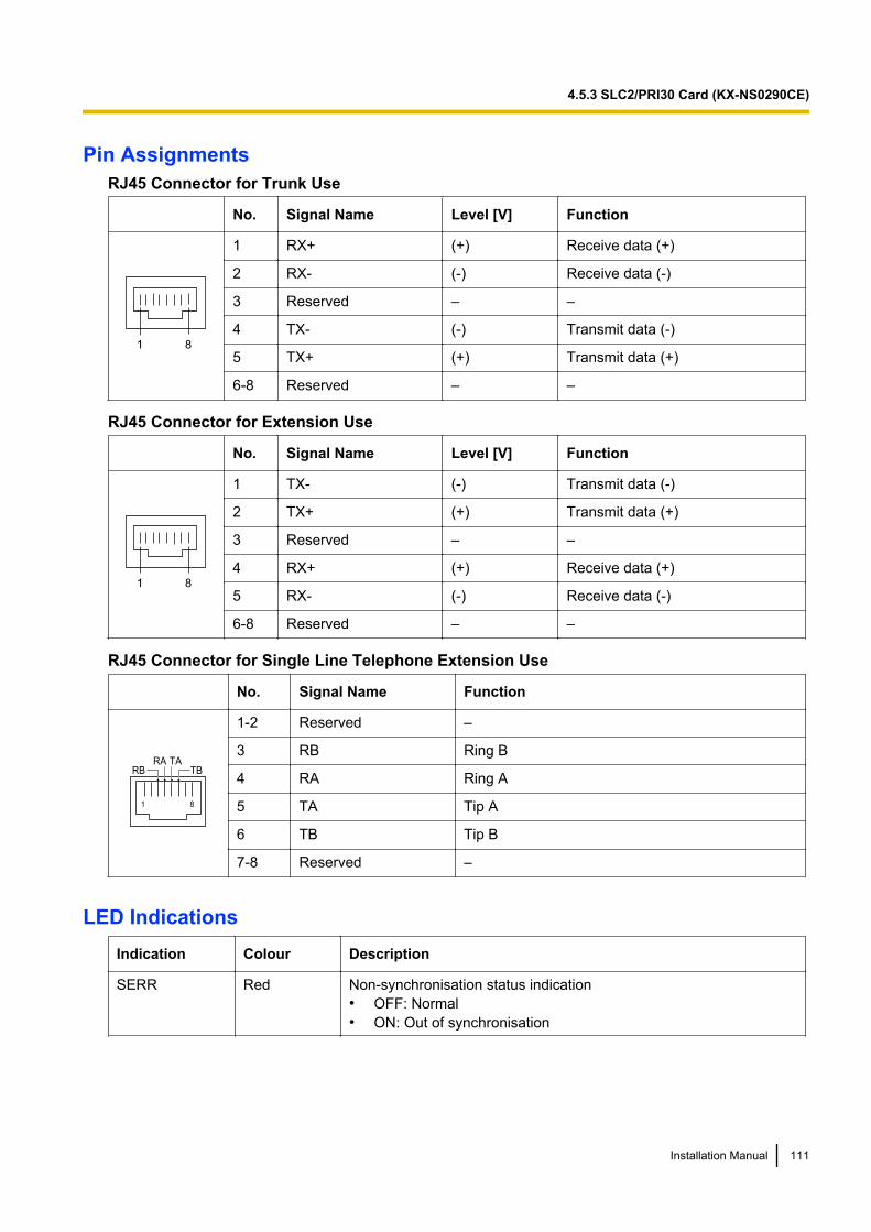
Pin AssignmentsRJ45 Connector for Trunk Use
No. Signal Name Level [V] Function
81
1 RX+ (+) Receive data (+)
2 RX- (-) Receive data (-)
3 Reserved – –
4 TX- (-) Transmit data (-)
5 TX+ (+) Transmit data (+)
6-8 Reserved – –
RJ45 Connector for Extension Use
No. Signal Name Level [V] Function
81
1 TX- (-) Transmit data (-)
2 TX+ (+) Transmit data (+)
3 Reserved – –
4 RX+ (+) Receive data (+)
5 RX- (-) Receive data (-)
6-8 Reserved – –
RJ45 Connector for Single Line Telephone Extension Use
No. Signal Name Function
1 8
RA TARB TB
1-2 Reserved –
3 RB Ring B
4 RA Ring A
5 TA Tip A
6 TB Tip B
7-8 Reserved –
LED IndicationsIndication Colour Description
SERR Red Non-synchronisation status indication• OFF: Normal• ON: Out of synchronisation
Installation Manual 111
4.5.3 SLC2/PRI30 Card (KX-NS0290CE)
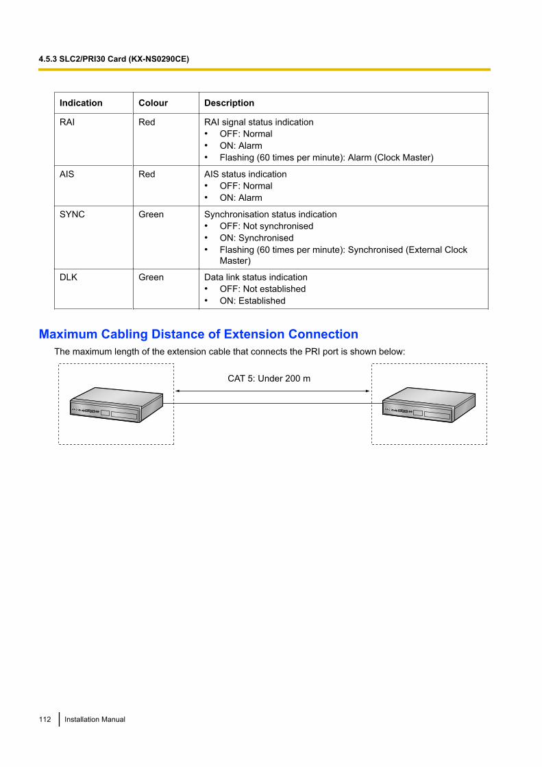
Indication Colour Description
RAI Red RAI signal status indication• OFF: Normal• ON: Alarm• Flashing (60 times per minute): Alarm (Clock Master)
AIS Red AIS status indication• OFF: Normal• ON: Alarm
SYNC Green Synchronisation status indication• OFF: Not synchronised• ON: Synchronised• Flashing (60 times per minute): Synchronised (External Clock
Master)
DLK Green Data link status indication• OFF: Not established• ON: Established
Maximum Cabling Distance of Extension ConnectionThe maximum length of the extension cable that connects the PRI port is shown below:
CAT 5: Under 200 m
112 Installation Manual
4.5.3 SLC2/PRI30 Card (KX-NS0290CE)
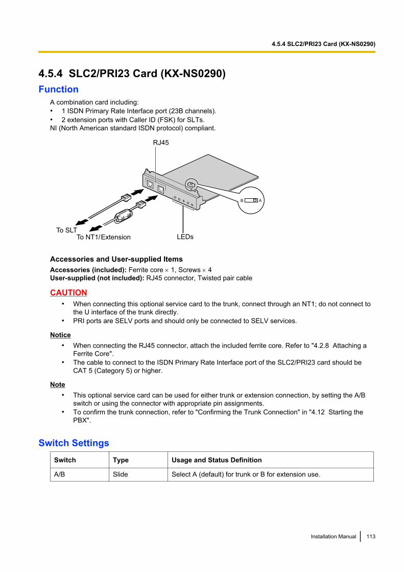
4.5.4 SLC2/PRI23 Card (KX-NS0290)Function
A combination card including:• 1 ISDN Primary Rate Interface port (23B channels).• 2 extension ports with Caller ID (FSK) for SLTs.NI (North American standard ISDN protocol) compliant.
LEDs
RJ45
To NT1/ ExtensionTo SLT
B A
Accessories and User-supplied ItemsAccessories (included): Ferrite core ´ 1, Screws ´ 4User-supplied (not included): RJ45 connector, Twisted pair cable
CAUTION• When connecting this optional service card to the trunk, connect through an NT1; do not connect to
the U interface of the trunk directly.• PRI ports are SELV ports and should only be connected to SELV services.
Notice• When connecting the RJ45 connector, attach the included ferrite core. Refer to "4.2.8 Attaching a
Ferrite Core".• The cable to connect to the ISDN Primary Rate Interface port of the SLC2/PRI23 card should be
CAT 5 (Category 5) or higher.
Note• This optional service card can be used for either trunk or extension connection, by setting the A/B
switch or using the connector with appropriate pin assignments.• To confirm the trunk connection, refer to "Confirming the Trunk Connection" in "4.12 Starting the
PBX".
Switch SettingsSwitch Type Usage and Status Definition
A/B Slide Select A (default) for trunk or B for extension use.
Installation Manual 113
4.5.4 SLC2/PRI23 Card (KX-NS0290)
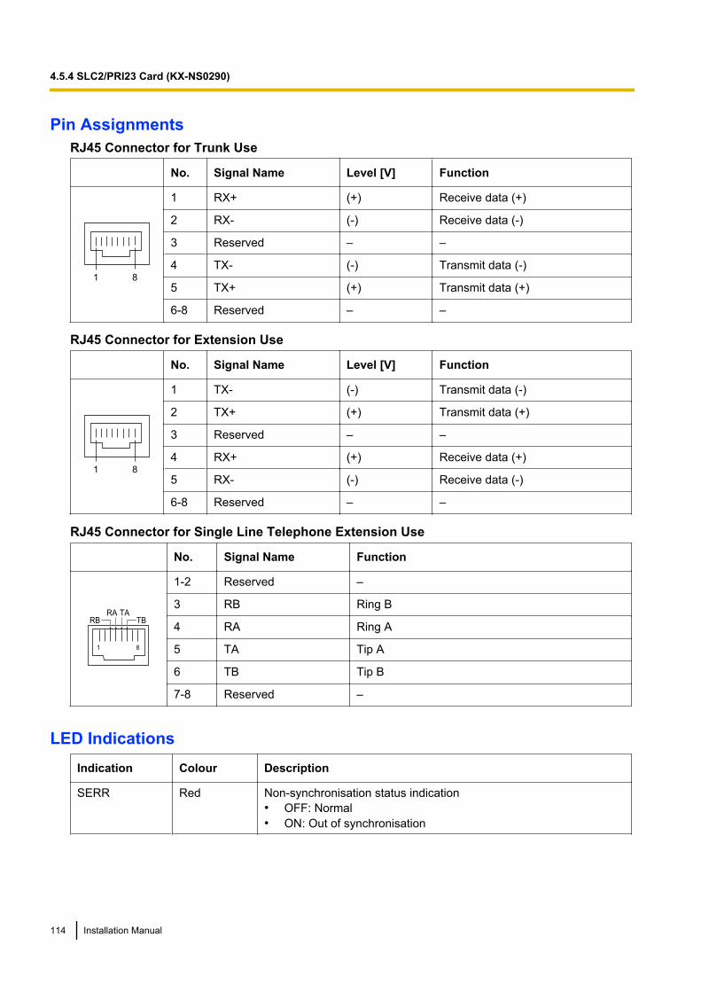
Pin AssignmentsRJ45 Connector for Trunk Use
No. Signal Name Level [V] Function
81
1 RX+ (+) Receive data (+)
2 RX- (-) Receive data (-)
3 Reserved – –
4 TX- (-) Transmit data (-)
5 TX+ (+) Transmit data (+)
6-8 Reserved – –
RJ45 Connector for Extension Use
No. Signal Name Level [V] Function
81
1 TX- (-) Transmit data (-)
2 TX+ (+) Transmit data (+)
3 Reserved – –
4 RX+ (+) Receive data (+)
5 RX- (-) Receive data (-)
6-8 Reserved – –
RJ45 Connector for Single Line Telephone Extension Use
No. Signal Name Function
1 8
RA TARB TB
1-2 Reserved –
3 RB Ring B
4 RA Ring A
5 TA Tip A
6 TB Tip B
7-8 Reserved –
LED IndicationsIndication Colour Description
SERR Red Non-synchronisation status indication• OFF: Normal• ON: Out of synchronisation
114 Installation Manual
4.5.4 SLC2/PRI23 Card (KX-NS0290)
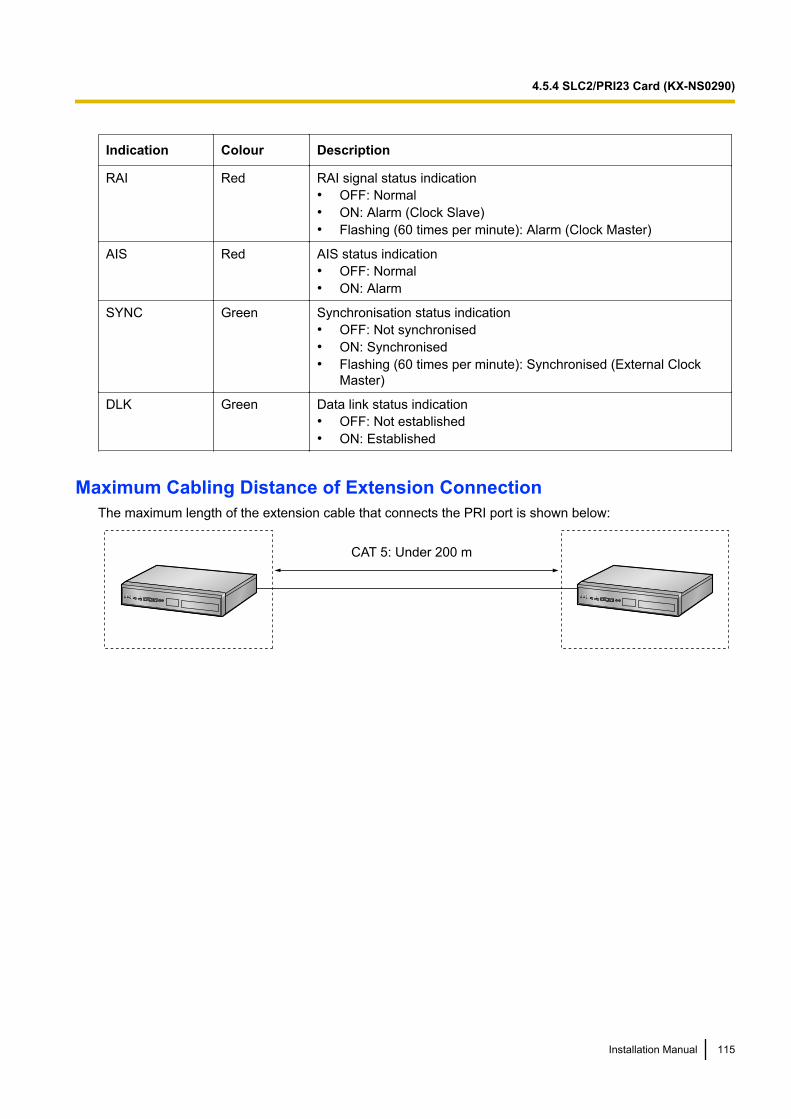
Indication Colour Description
RAI Red RAI signal status indication• OFF: Normal• ON: Alarm (Clock Slave)• Flashing (60 times per minute): Alarm (Clock Master)
AIS Red AIS status indication• OFF: Normal• ON: Alarm
SYNC Green Synchronisation status indication• OFF: Not synchronised• ON: Synchronised• Flashing (60 times per minute): Synchronised (External Clock
Master)
DLK Green Data link status indication• OFF: Not established• ON: Established
Maximum Cabling Distance of Extension ConnectionThe maximum length of the extension cable that connects the PRI port is shown below:
CAT 5: Under 200 m
Installation Manual 115
4.5.4 SLC2/PRI23 Card (KX-NS0290)
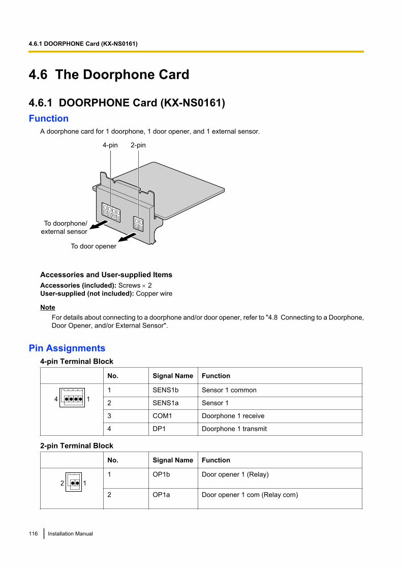
4.6 The Doorphone Card
4.6.1 DOORPHONE Card (KX-NS0161)Function
A doorphone card for 1 doorphone, 1 door opener, and 1 external sensor.
To door opener
To doorphone/
external sensor
4-pin 2-pin
Accessories and User-supplied ItemsAccessories (included): Screws ´ 2User-supplied (not included): Copper wire
NoteFor details about connecting to a doorphone and/or door opener, refer to "4.8 Connecting to a Doorphone,Door Opener, and/or External Sensor".
Pin Assignments4-pin Terminal Block
No. Signal Name Function
4 1
1 SENS1b Sensor 1 common
2 SENS1a Sensor 1
3 COM1 Doorphone 1 receive
4 DP1 Doorphone 1 transmit
2-pin Terminal Block
No. Signal Name Function
2 1
1 OP1b Door opener 1 (Relay)
2 OP1a Door opener 1 com (Relay com)
116 Installation Manual
4.6.1 DOORPHONE Card (KX-NS0161)
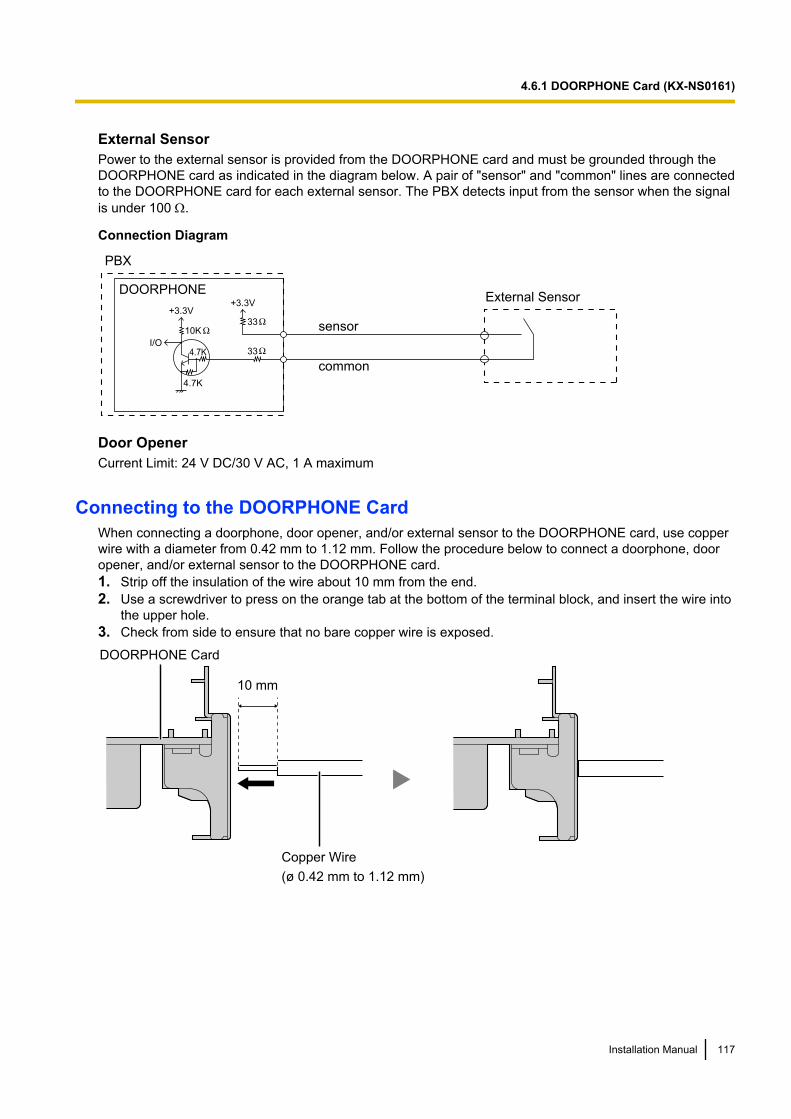
External SensorPower to the external sensor is provided from the DOORPHONE card and must be grounded through theDOORPHONE card as indicated in the diagram below. A pair of "sensor" and "common" lines are connectedto the DOORPHONE card for each external sensor. The PBX detects input from the sensor when the signalis under 100 W.
Connection Diagram
External Sensor
sensor
common
I/O
DOORPHONE
PBX
+3.3V+3.3V
10K33
334.7K
4.7K
Door OpenerCurrent Limit: 24 V DC/30 V AC, 1 A maximum
Connecting to the DOORPHONE CardWhen connecting a doorphone, door opener, and/or external sensor to the DOORPHONE card, use copperwire with a diameter from 0.42 mm to 1.12 mm. Follow the procedure below to connect a doorphone, dooropener, and/or external sensor to the DOORPHONE card.1. Strip off the insulation of the wire about 10 mm from the end.2. Use a screwdriver to press on the orange tab at the bottom of the terminal block, and insert the wire into
the upper hole.3. Check from side to ensure that no bare copper wire is exposed.
10 mm
Copper Wire
DOORPHONE Card
(ø 0.42 mm to 1.12 mm)
Installation Manual 117
4.6.1 DOORPHONE Card (KX-NS0161)
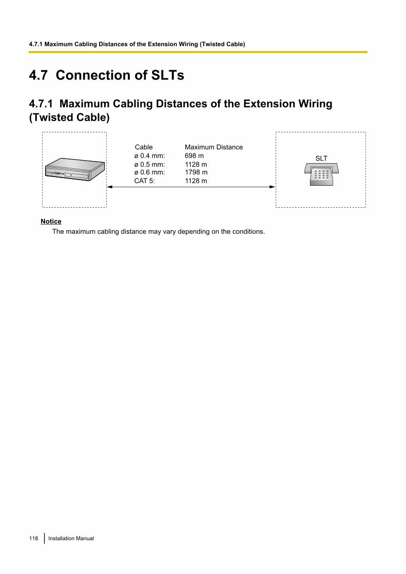
4.7 Connection of SLTs
4.7.1 Maximum Cabling Distances of the Extension Wiring(Twisted Cable)
Cable Maximum Distance
ø 0.4 mm: 698 m
ø 0.5 mm: 1128 mø 0.6 mm: 1798 m
CAT 5: 1128 m
SLT
NoticeThe maximum cabling distance may vary depending on the conditions.
118 Installation Manual
4.7.1 Maximum Cabling Distances of the Extension Wiring (Twisted Cable)
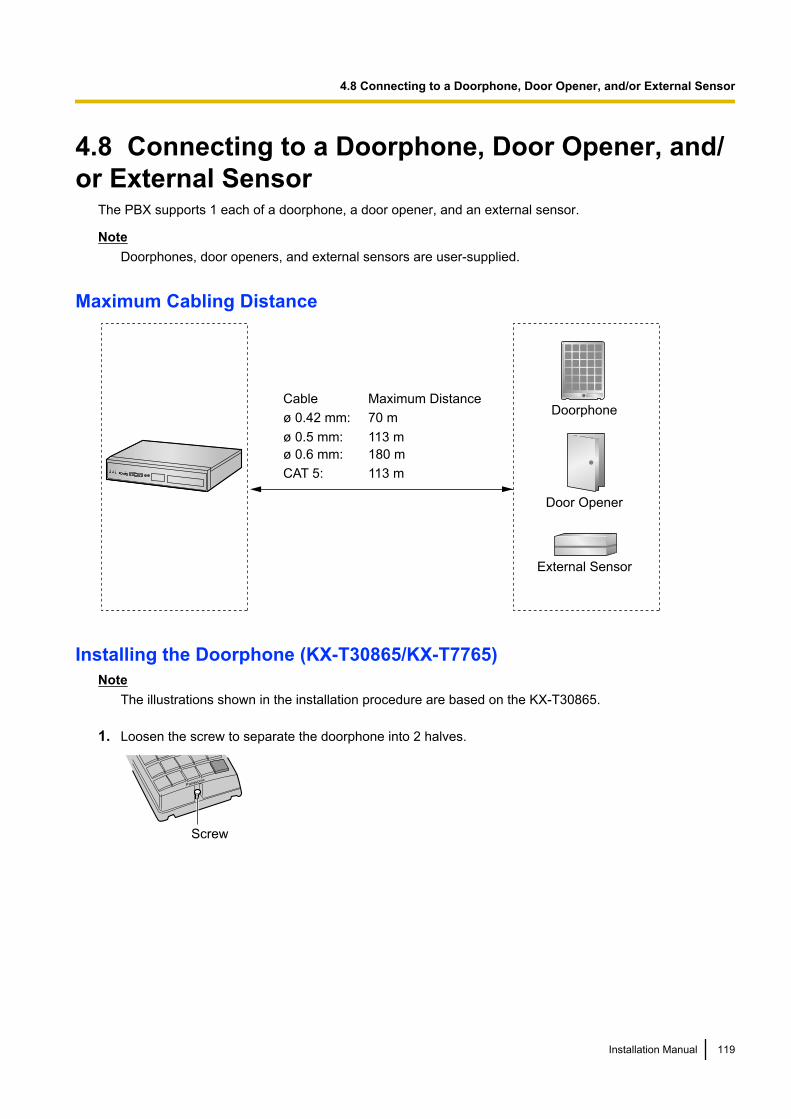
4.8 Connecting to a Doorphone, Door Opener, and/or External Sensor
The PBX supports 1 each of a doorphone, a door opener, and an external sensor.
NoteDoorphones, door openers, and external sensors are user-supplied.
Maximum Cabling Distance
Doorphone
Door Opener
Cable Maximum Distance
ø 0.42 mm: 70 m
ø 0.5 mm: 113 m
ø 0.6 mm: 180 m
CAT 5: 113 m
External Sensor
Installing the Doorphone (KX-T30865/KX-T7765)Note
The illustrations shown in the installation procedure are based on the KX-T30865.
1. Loosen the screw to separate the doorphone into 2 halves.
Panasonic
Screw
Installation Manual 119
4.8 Connecting to a Doorphone, Door Opener, and/or External Sensor
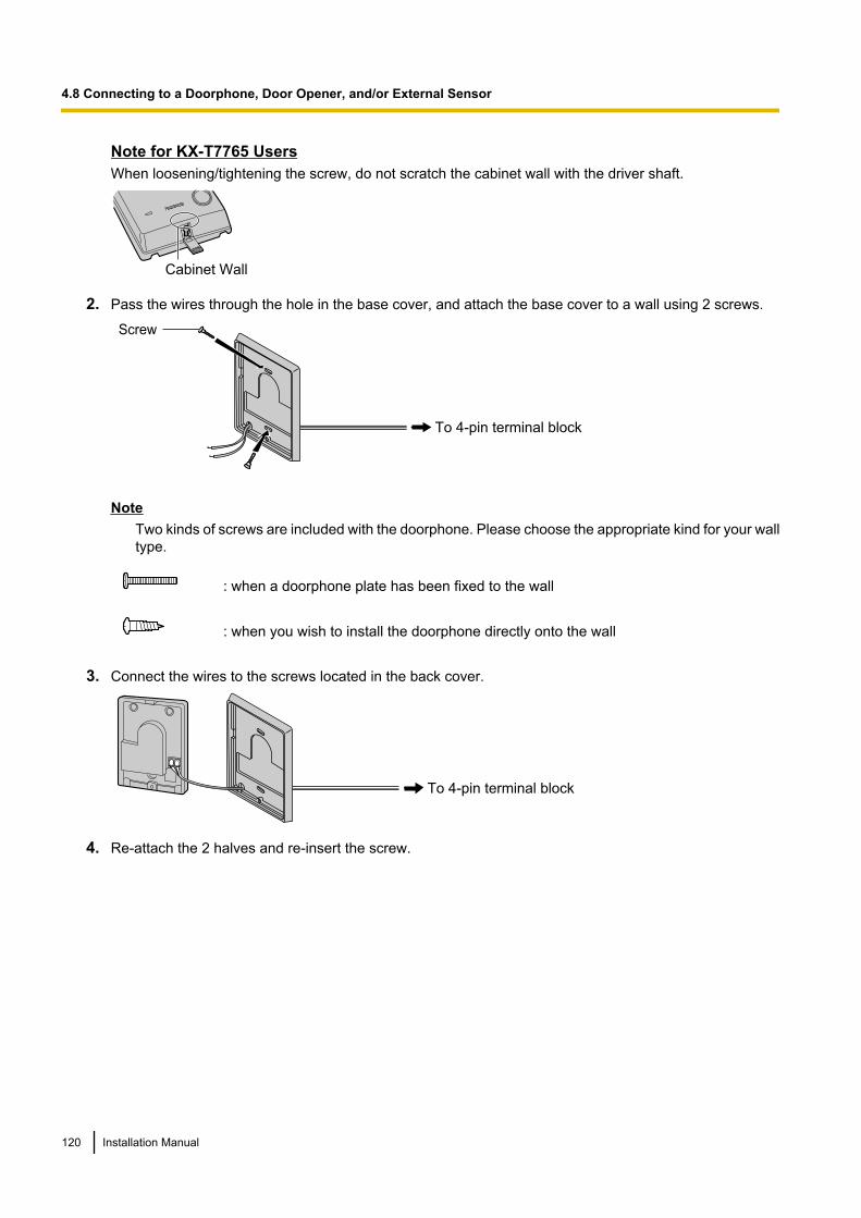
Note for KX-T7765 UsersWhen loosening/tightening the screw, do not scratch the cabinet wall with the driver shaft.
Cabinet Wall
2. Pass the wires through the hole in the base cover, and attach the base cover to a wall using 2 screws.
Screw
To 4-pin terminal block
NoteTwo kinds of screws are included with the doorphone. Please choose the appropriate kind for your walltype.
: when a doorphone plate has been fixed to the wall
: when you wish to install the doorphone directly onto the wall
3. Connect the wires to the screws located in the back cover.
To 4-pin terminal block
4. Re-attach the 2 halves and re-insert the screw.
120 Installation Manual
4.8 Connecting to a Doorphone, Door Opener, and/or External Sensor
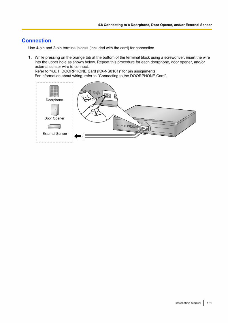
ConnectionUse 4-pin and 2-pin terminal blocks (included with the card) for connection.
1. While pressing on the orange tab at the bottom of the terminal block using a screwdriver, insert the wireinto the upper hole as shown below. Repeat this procedure for each doorphone, door opener, and/orexternal sensor wire to connect.Refer to "4.6.1 DOORPHONE Card (KX-NS0161)" for pin assignments.For information about wiring, refer to "Connecting to the DOORPHONE Card".
Doorphone
Door Opener
External Sensor
Installation Manual 121
4.8 Connecting to a Doorphone, Door Opener, and/or External Sensor
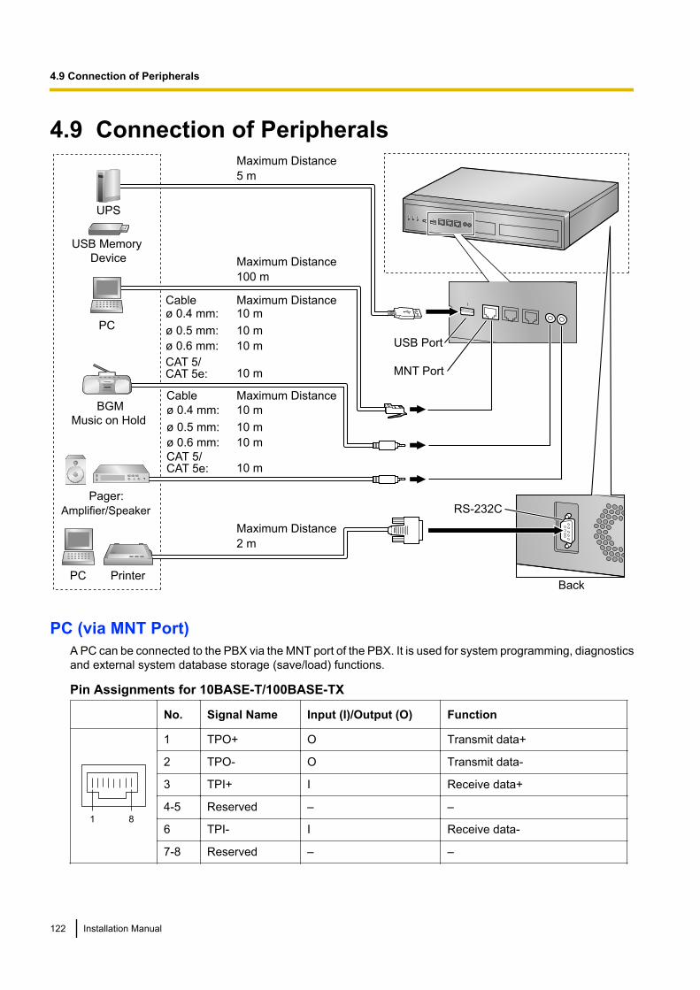
4.9 Connection of Peripherals
Cable Maximum Distance
Maximum Distance
Cable Maximum Distance
Maximum Distance
PC
BGM
Music on Hold
Pager:
Amplifier/Speaker
Printer
ø 0.4 mm: 10 m
ø 0.5 mm: 10 m
ø 0.6 mm: 10 m
CAT 5/CAT 5e: 10 m
100 m
ø 0.4 mm: 10 m
ø 0.5 mm: 10 m
ø 0.6 mm: 10 m
CAT 5/ CAT 5e: 10 m
2 m
Back
MNT Port
RS-232C
UPS
USB Port
Maximum Distance
5 m
PC
USB Memory
Device
PC (via MNT Port)A PC can be connected to the PBX via the MNT port of the PBX. It is used for system programming, diagnosticsand external system database storage (save/load) functions.
Pin Assignments for 10BASE-T/100BASE-TX
No. Signal Name Input (I)/Output (O) Function
81
1 TPO+ O Transmit data+
2 TPO- O Transmit data-
3 TPI+ I Receive data+
4-5 Reserved – –
6 TPI- I Receive data-
7-8 Reserved – –
122 Installation Manual
4.9 Connection of Peripherals
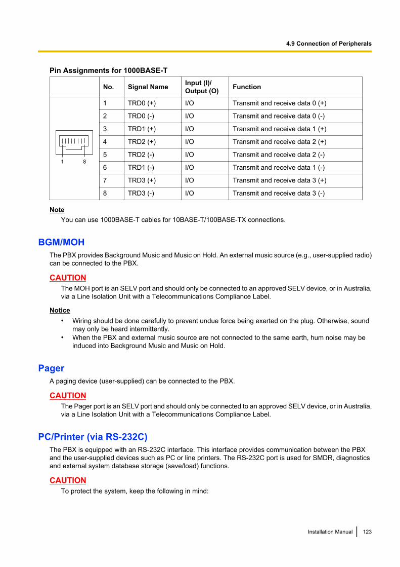
Pin Assignments for 1000BASE-T
No. Signal Name Input (I)/Output (O) Function
81
1 TRD0 (+) I/O Transmit and receive data 0 (+)
2 TRD0 (-) I/O Transmit and receive data 0 (-)
3 TRD1 (+) I/O Transmit and receive data 1 (+)
4 TRD2 (+) I/O Transmit and receive data 2 (+)
5 TRD2 (-) I/O Transmit and receive data 2 (-)
6 TRD1 (-) I/O Transmit and receive data 1 (-)
7 TRD3 (+) I/O Transmit and receive data 3 (+)
8 TRD3 (-) I/O Transmit and receive data 3 (-)
NoteYou can use 1000BASE-T cables for 10BASE-T/100BASE-TX connections.
BGM/MOHThe PBX provides Background Music and Music on Hold. An external music source (e.g., user-supplied radio)can be connected to the PBX.
CAUTIONThe MOH port is an SELV port and should only be connected to an approved SELV device, or in Australia,via a Line Isolation Unit with a Telecommunications Compliance Label.
Notice• Wiring should be done carefully to prevent undue force being exerted on the plug. Otherwise, sound
may only be heard intermittently.• When the PBX and external music source are not connected to the same earth, hum noise may be
induced into Background Music and Music on Hold.
PagerA paging device (user-supplied) can be connected to the PBX.
CAUTIONThe Pager port is an SELV port and should only be connected to an approved SELV device, or in Australia,via a Line Isolation Unit with a Telecommunications Compliance Label.
PC/Printer (via RS-232C)The PBX is equipped with an RS-232C interface. This interface provides communication between the PBXand the user-supplied devices such as PC or line printers. The RS-232C port is used for SMDR, diagnosticsand external system database storage (save/load) functions.
CAUTIONTo protect the system, keep the following in mind:
Installation Manual 123
4.9 Connection of Peripherals
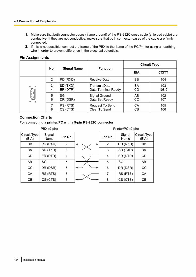
1. Make sure that both connector cases (frame ground) of the RS-232C cross cable (shielded cable) areconductive. If they are not conductive, make sure that both connector cases of the cable are firmlyconnected.
2. If this is not possible, connect the frame of the PBX to the frame of the PC/Printer using an earthingwire in order to prevent difference in the electrical potentials.
Pin Assignments
No. Signal Name FunctionCircuit Type
EIA CCITT
9 5
6 1
2 RD (RXD) Receive Data BB 104
34
SD (TXD)ER (DTR)
Transmit DataData Terminal Ready
BACD
103108.2
56
SGDR (DSR)
Signal GroundData Set Ready
ABCC
102107
78
RS (RTS)CS (CTS)
Request To SendClear To Send
CACB
105106
Connection ChartsFor connecting a printer/PC with a 9-pin RS-232C connector
Printer/PC (9-pin)
Circuit Type
(EIA)
BB
BA
CD
AB
CC
CA
CB
Signal
Name
RD (RXD)
SD (TXD)
ER (DTR)
SG
DR (DSR)
RS (RTS)
CS (CTS)
Pin No.
2
3
4
5
6
7
8
PBX (9-pin)
Signal
NamePin No.
RD (RXD) 2
SD (TXD) 3
ER (DTR) 4
SG 5
DR (DSR) 6
RS (RTS) 7
CS (CTS) 8
Circuit Type
(EIA)
BB
BA
CD
AB
CC
CA
CB
124 Installation Manual
4.9 Connection of Peripherals
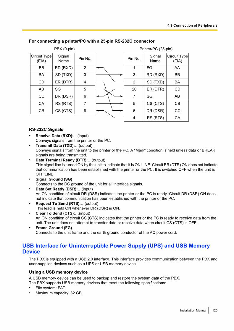
For connecting a printer/PC with a 25-pin RS-232C connector
Printer/PC (25-pin)
Signal
Name
Circuit Type
(EIA)
1 FG AA
3 RD (RXD) BB
2 SD (TXD) BA
20 ER (DTR) CD
7 SG AB
5 CS (CTS) CB
6 DR (DSR) CC
CA4 RS (RTS)
Pin No.
PBX (9-pin)
Circuit Type
(EIA)
Signal
NamePin No.
BB RD (RXD) 2
BA SD (TXD) 3
CD ER (DTR) 4
AB SG 5
CC DR (DSR) 6
CA RS (RTS) 7
CB CS (CTS) 8
RS-232C Signals• Receive Data (RXD):…(input)
Conveys signals from the printer or the PC.• Transmit Data (TXD):…(output)
Conveys signals from the unit to the printer or the PC. A "Mark" condition is held unless data or BREAKsignals are being transmitted.
• Data Terminal Ready (DTR):…(output)This signal line is turned ON by the unit to indicate that it is ON LINE. Circuit ER (DTR) ON does not indicatethat communication has been established with the printer or the PC. It is switched OFF when the unit isOFF LINE.
• Signal Ground (SG)Connects to the DC ground of the unit for all interface signals.
• Data Set Ready (DSR):…(input)An ON condition of circuit DR (DSR) indicates the printer or the PC is ready. Circuit DR (DSR) ON doesnot indicate that communication has been established with the printer or the PC.
• Request To Send (RTS):…(output)This lead is held ON whenever DR (DSR) is ON.
• Clear To Send (CTS):…(input)An ON condition of circuit CS (CTS) indicates that the printer or the PC is ready to receive data from theunit. The unit does not attempt to transfer data or receive data when circuit CS (CTS) is OFF.
• Frame Ground (FG)Connects to the unit frame and the earth ground conductor of the AC power cord.
USB Interface for Uninterruptible Power Supply (UPS) and USB MemoryDevice
The PBX is equipped with a USB 2.0 interface. This interface provides communication between the PBX anduser-supplied devices such as a UPS or USB memory device.
Using a USB memory deviceA USB memory device can be used to backup and restore the system data of the PBX.The PBX supports USB memory devices that meet the following specifications:• File system: FAT• Maximum capacity: 32 GB
Installation Manual 125
4.9 Connection of Peripherals
• Maximum current: 500 mAFor details about backing up and restoring using a USB memory device, refer to "6.1 Tool—System DataBackup to USB" in the PC Programming Manual.
NoteDo not use a USB hub when connecting a USB memory device to the PBX.
Using a UPSA UPS is a device that supplies power for several minutes to a connected device when a power failure occurs.For details about connecting a UPS to the PBX, refer to "Connecting an Uninterruptible Power Supply(UPS)".
NoteWhen connecting a UPS, use only the USB cable included with the UPS, and do not use a USB hub.
126 Installation Manual
4.9 Connection of Peripherals
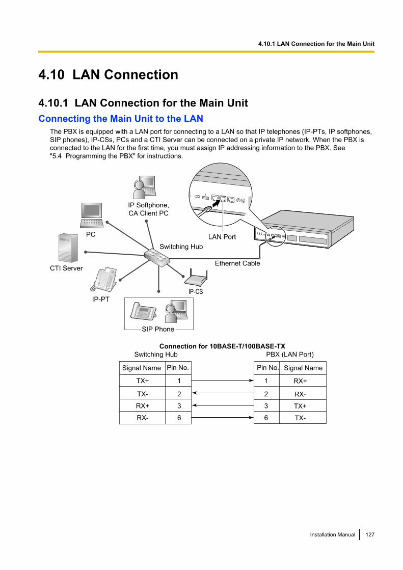
4.10 LAN Connection
4.10.1 LAN Connection for the Main UnitConnecting the Main Unit to the LAN
The PBX is equipped with a LAN port for connecting to a LAN so that IP telephones (IP-PTs, IP softphones,SIP phones), IP-CSs, PCs and a CTI Server can be connected on a private IP network. When the PBX isconnected to the LAN for the first time, you must assign IP addressing information to the PBX. See"5.4 Programming the PBX" for instructions.
TX+
TX-
RX+
RX-
1
2
3
6
1
2
3
6
RX+
RX-
TX+
TX-
PC
CTI Server
IP-PT
Switching Hub
IP Softphone,
CA Client PC
Switching Hub PBX (LAN Port)
Pin No.Signal Name Signal NamePin No.
LAN Port
SIP Phone
IP-CS
Connection for 10BASE-T/100BASE-TX
Ethernet Cable
Installation Manual 127
4.10.1 LAN Connection for the Main Unit
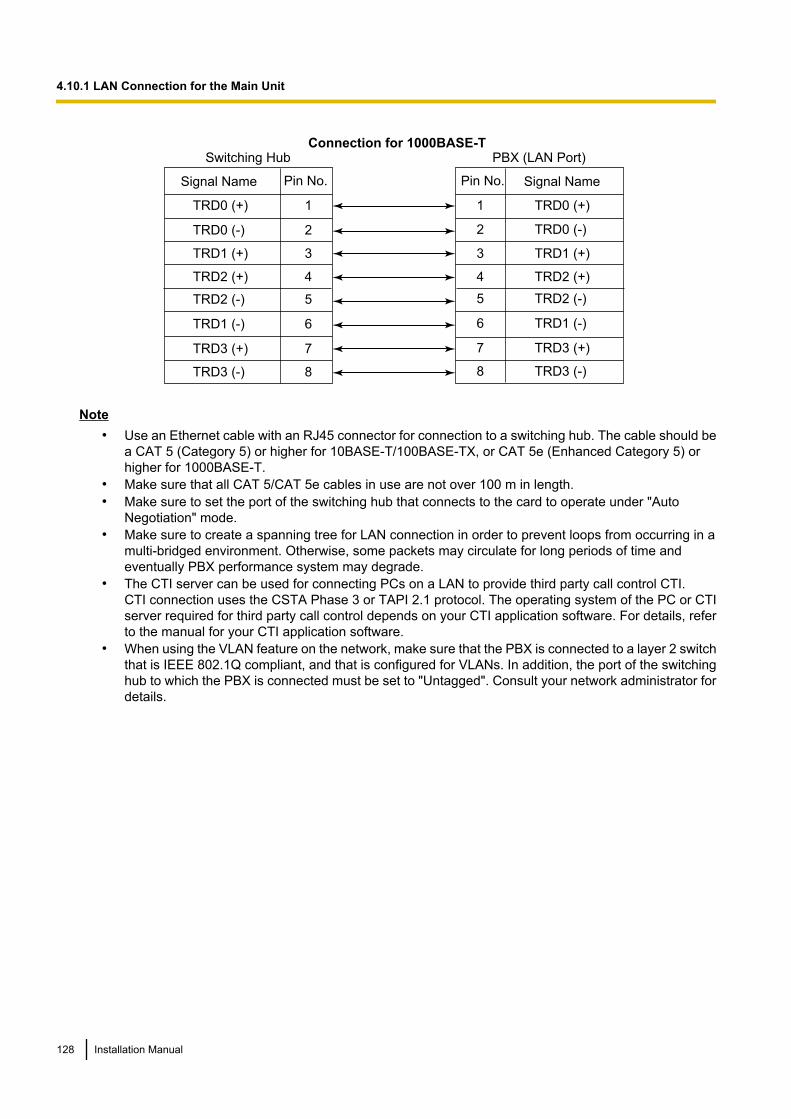
TRD0 (+)
TRD0 (-)
TRD1 (+)
TRD2 (+)
1
2
3
4
Switching Hub PBX (LAN Port)
Pin No.Signal Name Signal NamePin No.
Connection for 1000BASE-T
TRD2 (-)
TRD1 (-)
TRD3 (+)
TRD3 (-)
5
6
7
8
TRD0 (+)
TRD0 (-)
TRD1 (+)
TRD2 (+)
TRD2 (-)
TRD1 (-)
TRD3 (+)
TRD3 (-)
1
2
3
4
5
6
7
8
Note• Use an Ethernet cable with an RJ45 connector for connection to a switching hub. The cable should be
a CAT 5 (Category 5) or higher for 10BASE-T/100BASE-TX, or CAT 5e (Enhanced Category 5) orhigher for 1000BASE-T.
• Make sure that all CAT 5/CAT 5e cables in use are not over 100 m in length.• Make sure to set the port of the switching hub that connects to the card to operate under "Auto
Negotiation" mode.• Make sure to create a spanning tree for LAN connection in order to prevent loops from occurring in a
multi-bridged environment. Otherwise, some packets may circulate for long periods of time andeventually PBX performance system may degrade.
• The CTI server can be used for connecting PCs on a LAN to provide third party call control CTI.CTI connection uses the CSTA Phase 3 or TAPI 2.1 protocol. The operating system of the PC or CTIserver required for third party call control depends on your CTI application software. For details, referto the manual for your CTI application software.
• When using the VLAN feature on the network, make sure that the PBX is connected to a layer 2 switchthat is IEEE 802.1Q compliant, and that is configured for VLANs. In addition, the port of the switchinghub to which the PBX is connected must be set to "Untagged". Consult your network administrator fordetails.
128 Installation Manual
4.10.1 LAN Connection for the Main Unit
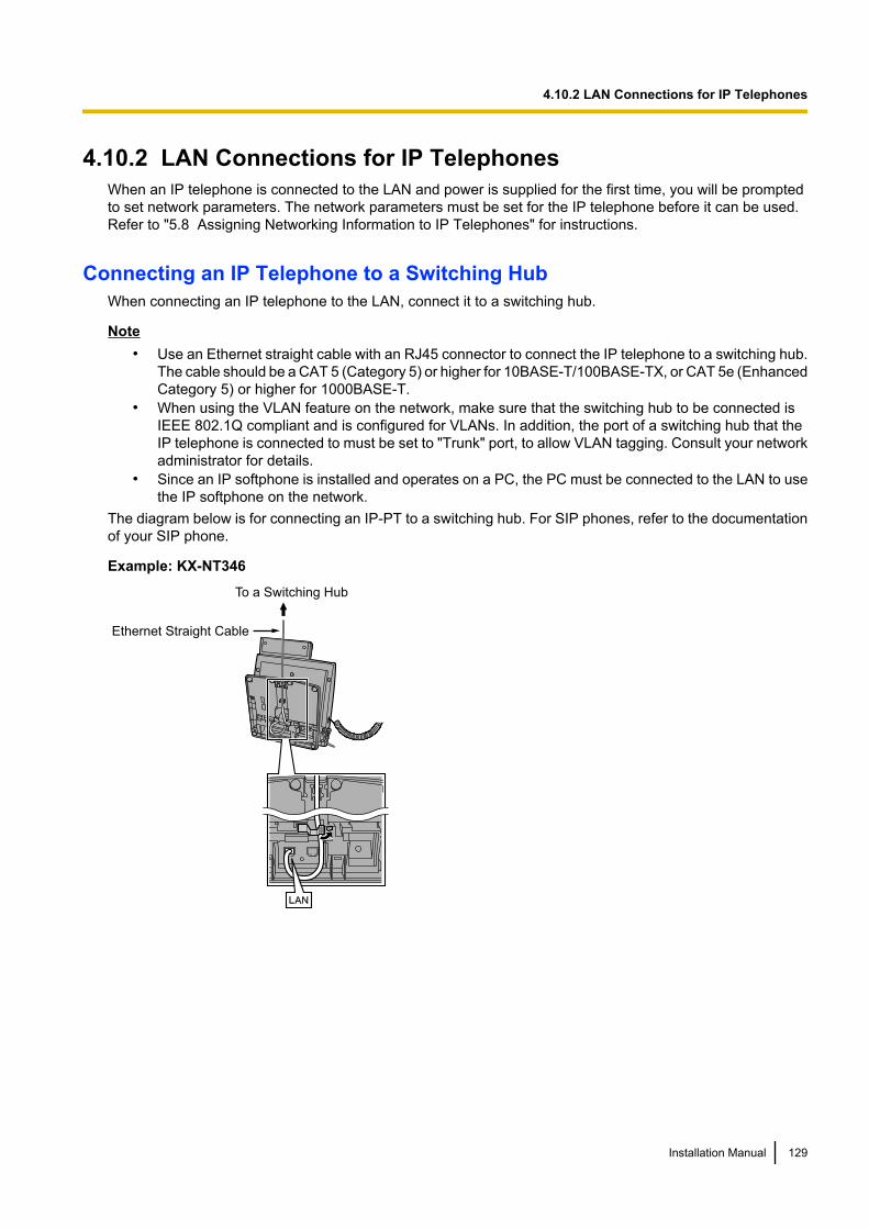
4.10.2 LAN Connections for IP TelephonesWhen an IP telephone is connected to the LAN and power is supplied for the first time, you will be promptedto set network parameters. The network parameters must be set for the IP telephone before it can be used.Refer to "5.8 Assigning Networking Information to IP Telephones" for instructions.
Connecting an IP Telephone to a Switching HubWhen connecting an IP telephone to the LAN, connect it to a switching hub.
Note• Use an Ethernet straight cable with an RJ45 connector to connect the IP telephone to a switching hub.
The cable should be a CAT 5 (Category 5) or higher for 10BASE-T/100BASE-TX, or CAT 5e (EnhancedCategory 5) or higher for 1000BASE-T.
• When using the VLAN feature on the network, make sure that the switching hub to be connected isIEEE 802.1Q compliant and is configured for VLANs. In addition, the port of a switching hub that theIP telephone is connected to must be set to "Trunk" port, to allow VLAN tagging. Consult your networkadministrator for details.
• Since an IP softphone is installed and operates on a PC, the PC must be connected to the LAN to usethe IP softphone on the network.
The diagram below is for connecting an IP-PT to a switching hub. For SIP phones, refer to the documentationof your SIP phone.
Example: KX-NT346
Ethernet Straight Cable
To a Switching Hub
Installation Manual 129
4.10.2 LAN Connections for IP Telephones
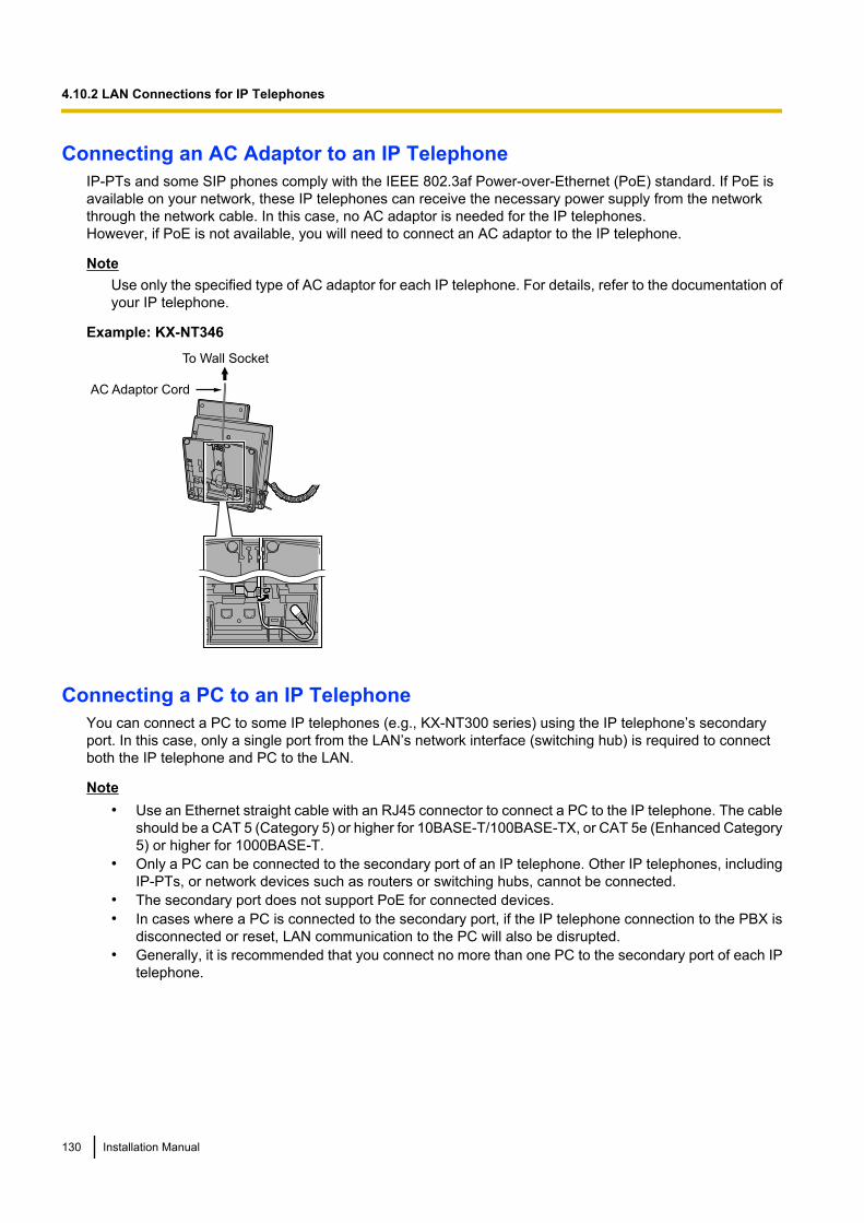
Connecting an AC Adaptor to an IP TelephoneIP-PTs and some SIP phones comply with the IEEE 802.3af Power-over-Ethernet (PoE) standard. If PoE isavailable on your network, these IP telephones can receive the necessary power supply from the networkthrough the network cable. In this case, no AC adaptor is needed for the IP telephones.However, if PoE is not available, you will need to connect an AC adaptor to the IP telephone.
NoteUse only the specified type of AC adaptor for each IP telephone. For details, refer to the documentation ofyour IP telephone.
Example: KX-NT346
AC Adaptor Cord
To Wall Socket
Connecting a PC to an IP TelephoneYou can connect a PC to some IP telephones (e.g., KX-NT300 series) using the IP telephone’s secondaryport. In this case, only a single port from the LAN’s network interface (switching hub) is required to connectboth the IP telephone and PC to the LAN.
Note• Use an Ethernet straight cable with an RJ45 connector to connect a PC to the IP telephone. The cable
should be a CAT 5 (Category 5) or higher for 10BASE-T/100BASE-TX, or CAT 5e (Enhanced Category5) or higher for 1000BASE-T.
• Only a PC can be connected to the secondary port of an IP telephone. Other IP telephones, includingIP-PTs, or network devices such as routers or switching hubs, cannot be connected.
• The secondary port does not support PoE for connected devices.• In cases where a PC is connected to the secondary port, if the IP telephone connection to the PBX is
disconnected or reset, LAN communication to the PC will also be disrupted.• Generally, it is recommended that you connect no more than one PC to the secondary port of each IP
telephone.
130 Installation Manual
4.10.2 LAN Connections for IP Telephones
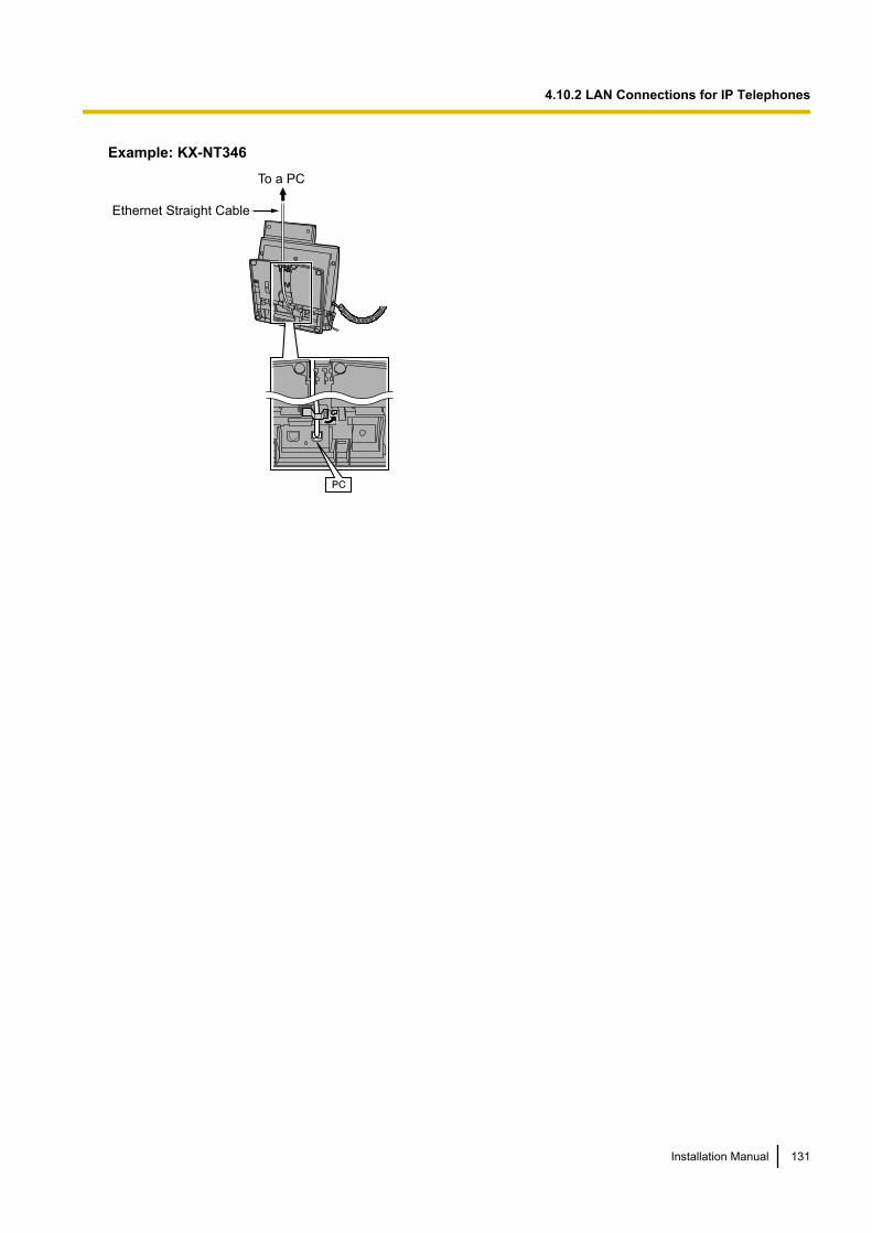
Example: KX-NT346
Ethernet Straight Cable
To a PC
Installation Manual 131
4.10.2 LAN Connections for IP Telephones
4.11 Power Failure PortsWhen the power supply to the PBX fails, power failure transfer (PFT) will switch from the current connectionto the Power Failure Connection. Refer to "5.5.2 Power Failure Transfer" in the Feature Guide for furtherinformation.
Using SLC2/LCOT2 CardIn the event of a power failure, a specific SLT is automatically supplied power through the PFT port. The PFTports are the SLC1 port and LCOT1 port on the SLC2/LCOT2 card.
NoteA trunk conversation established during power failure can be maintained even when the power returns andthe connection is switched back to the normal configuration from the Power Failure Connection.
132 Installation Manual
4.11 Power Failure Ports
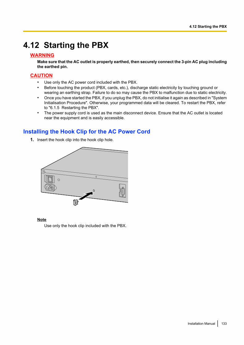
4.12 Starting the PBXWARNING
Make sure that the AC outlet is properly earthed, then securely connect the 3-pin AC plug includingthe earthed pin.
CAUTION• Use only the AC power cord included with the PBX.• Before touching the product (PBX, cards, etc.), discharge static electricity by touching ground or
wearing an earthing strap. Failure to do so may cause the PBX to malfunction due to static electricity.• Once you have started the PBX, if you unplug the PBX, do not initialise it again as described in "System
Initialisation Procedure". Otherwise, your programmed data will be cleared. To restart the PBX, referto "6.1.5 Restarting the PBX".
• The power supply cord is used as the main disconnect device. Ensure that the AC outlet is locatednear the equipment and is easily accessible.
Installing the Hook Clip for the AC Power Cord1. Insert the hook clip into the hook clip hole.
NoteUse only the hook clip included with the PBX.
Installation Manual 133
4.12 Starting the PBX
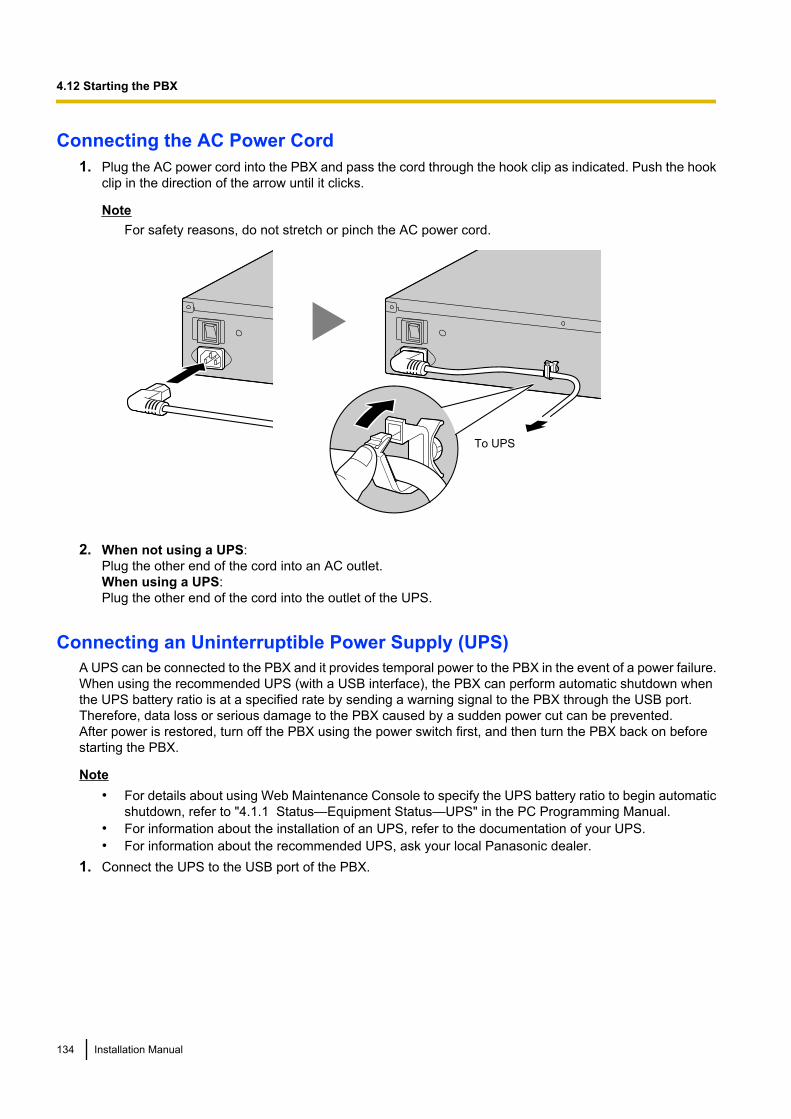
Connecting the AC Power Cord1. Plug the AC power cord into the PBX and pass the cord through the hook clip as indicated. Push the hook
clip in the direction of the arrow until it clicks.
NoteFor safety reasons, do not stretch or pinch the AC power cord.
To UPS
2. When not using a UPS:Plug the other end of the cord into an AC outlet.When using a UPS:Plug the other end of the cord into the outlet of the UPS.
Connecting an Uninterruptible Power Supply (UPS)A UPS can be connected to the PBX and it provides temporal power to the PBX in the event of a power failure.When using the recommended UPS (with a USB interface), the PBX can perform automatic shutdown whenthe UPS battery ratio is at a specified rate by sending a warning signal to the PBX through the USB port.Therefore, data loss or serious damage to the PBX caused by a sudden power cut can be prevented.After power is restored, turn off the PBX using the power switch first, and then turn the PBX back on beforestarting the PBX.
Note• For details about using Web Maintenance Console to specify the UPS battery ratio to begin automatic
shutdown, refer to "4.1.1 Status—Equipment Status—UPS" in the PC Programming Manual.• For information about the installation of an UPS, refer to the documentation of your UPS.• For information about the recommended UPS, ask your local Panasonic dealer.
1. Connect the UPS to the USB port of the PBX.
134 Installation Manual
4.12 Starting the PBX
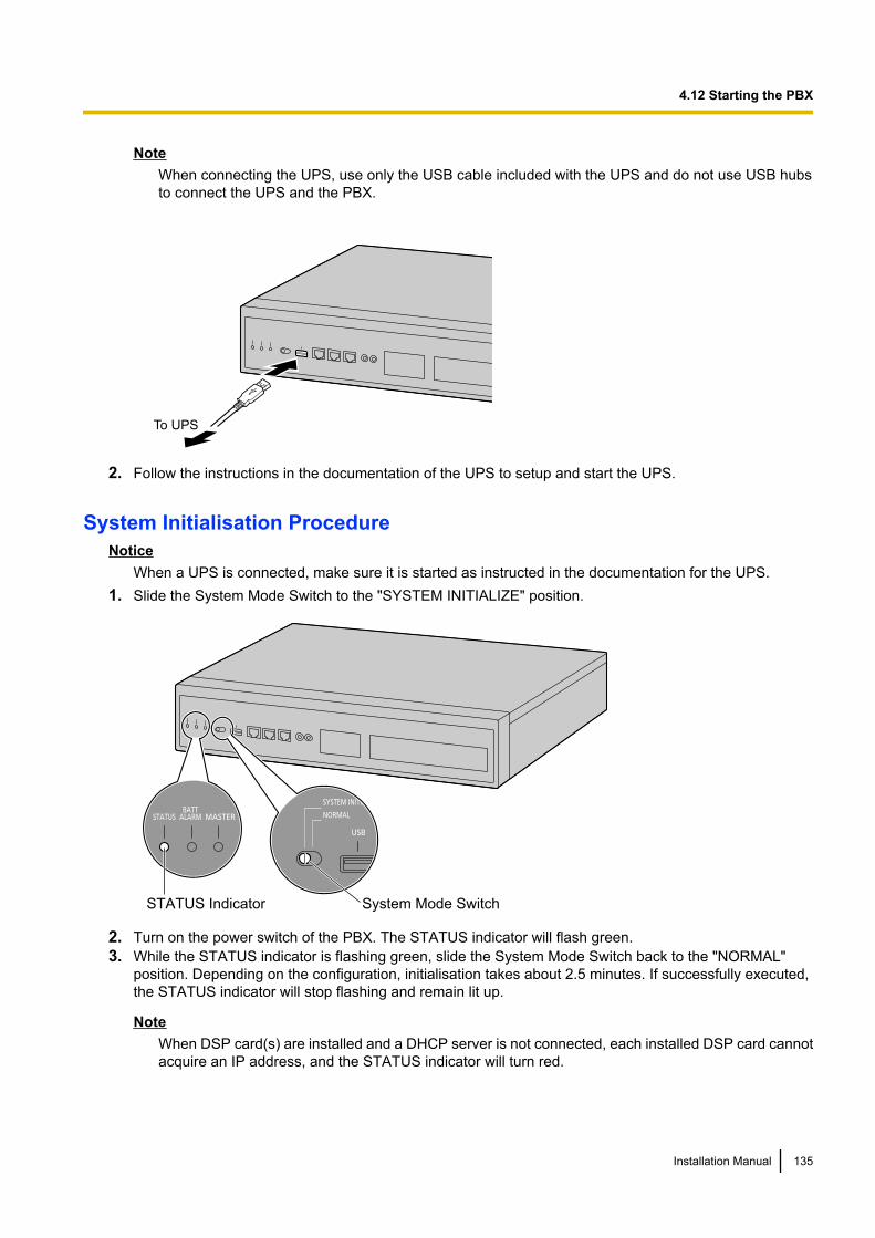
NoteWhen connecting the UPS, use only the USB cable included with the UPS and do not use USB hubsto connect the UPS and the PBX.
To UPS
2. Follow the instructions in the documentation of the UPS to setup and start the UPS.
System Initialisation ProcedureNotice
When a UPS is connected, make sure it is started as instructed in the documentation for the UPS.1. Slide the System Mode Switch to the "SYSTEM INITIALIZE" position.
STATUS Indicator System Mode Switch
2. Turn on the power switch of the PBX. The STATUS indicator will flash green.3. While the STATUS indicator is flashing green, slide the System Mode Switch back to the "NORMAL"
position. Depending on the configuration, initialisation takes about 2.5 minutes. If successfully executed,the STATUS indicator will stop flashing and remain lit up.
NoteWhen DSP card(s) are installed and a DHCP server is not connected, each installed DSP card cannotacquire an IP address, and the STATUS indicator will turn red.
Installation Manual 135
4.12 Starting the PBX
All data, except for system prompts and activation key files, will be erased. Data that is erased includes UnifiedMessaging data, call logs, etc. The settings for the PBX as well as all optional service cards will be initialisedto their default values.
Note• After the PBX is initialised, you can restore system data to the PBX that has been backed up earlier.
For details about backing up and restoring system data, refer to "6.1 Tool—System Data Backup toUSB", "7.2.2 Utility—File—File Transfer PBX to PC" and "7.2.1 Utility—File—File Transfer PC toPBX" in the PC Programming Manual.
• After the PBX is initialised, you must set up the mandatory settings required for both stand-alone PBXsand PBXs in a One-look network with Easy Setup Wizard. For details refer to "Connecting to WebMaintenance Console" and "5.4.1 Easy Setup Wizard".
Confirming the Trunk ConnectionAfter the SLC2/LCOT2 card is installed, programme the PBX and connect trunks to the PBX.If SLC2/LCOT2 card is not installed, this confirmation can be skipped.
To confirm that the trunks are successfully connected, dial [ ] [3] [7] + trunk number (3 digits) on an IPtelephone, or press the IP telephone’s S-CO button. You will hear a dial tone if the trunk is available andconnected.
136 Installation Manual
4.12 Starting the PBX
Section 5
Programming with Web Maintenance Console
This section describes the installation procedure,structure, and functions of the Web MaintenanceConsole for programming IP telephones and the PBX.Further information on programming the PBX for usewith SIP trunks and a VoIP network is included.
Installation Manual 137
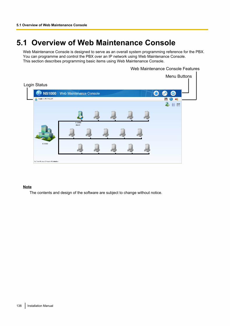
5.1 Overview of Web Maintenance ConsoleWeb Maintenance Console is designed to serve as an overall system programming reference for the PBX.You can programme and control the PBX over an IP network using Web Maintenance Console.This section describes programming basic items using Web Maintenance Console.
Login Status
Menu Buttons
Web Maintenance Console Features
NoteThe contents and design of the software are subject to change without notice.
138 Installation Manual
5.1 Overview of Web Maintenance Console

5.2 PC ConnectionKX-NS1000 has 3 physical ports for PC and LAN connections. A default IP address is assigned to each port.A PC connect to the PBX either directly or over a LAN using the appropriate method for the port being used.
Port Default IP Address
MNT Port 223.0.0.1
LAN Port 192.168.0.101
WAN Port*1 Not Used
*1 The WAN Port is not used with PCMPR Software Version 001.10000.
Direct Connection
To LAN Port
MNT Port
NoticeWhen connecting the PC to the MNT port, if the PC is set to obtain the IP address automatically, the IPaddress of the PC will be set to an appropriate IP address to establish a connection to the PBX.
Note• Use an Ethernet cable with an RJ45 connector to connect a PC to the PBX.• For pin assignments and maximum cabling distance, refer to "4.9 Connection of Peripherals".
Connection via LAN
Switching Hub
LAN Port
LAN
PC
Installation Manual 139
5.2 PC Connection
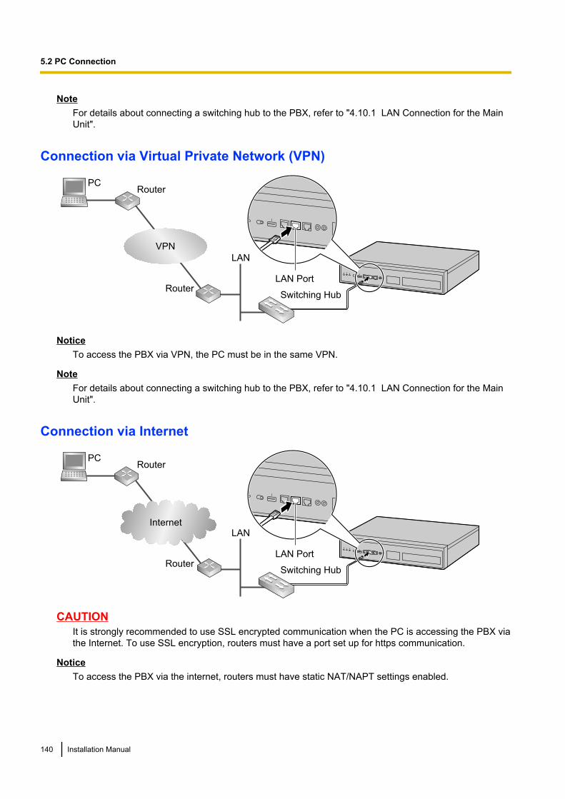
NoteFor details about connecting a switching hub to the PBX, refer to "4.10.1 LAN Connection for the MainUnit".
Connection via Virtual Private Network (VPN)
Switching Hub
LAN Port
LAN
PCRouter
Router
VPN
NoticeTo access the PBX via VPN, the PC must be in the same VPN.
NoteFor details about connecting a switching hub to the PBX, refer to "4.10.1 LAN Connection for the MainUnit".
Connection via Internet
Switching Hub
LAN Port
LAN
PCRouter
Router
Internet
CAUTIONIt is strongly recommended to use SSL encrypted communication when the PC is accessing the PBX viathe Internet. To use SSL encryption, routers must have a port set up for https communication.
NoticeTo access the PBX via the internet, routers must have static NAT/NAPT settings enabled.
140 Installation Manual
5.2 PC Connection

NoteFor details about connecting a switching hub to the PBX, refer to "4.10.1 LAN Connection for the MainUnit".
Installation Manual 141
5.2 PC Connection
5.3 Starting Web Maintenance ConsoleSystem Requirements
Required Operating System• Microsoft® Windows® XP, Windows Vista® Business, or Windows 7 Professional operating system
Recommended Display Settings• Screen resolution: XGA (1024 ´ 768)• DPI setting: Normal size (96 DPI)
Supported Browsers for use with Web Maintenance Console• Windows Internet Explorer® 8• Windows Internet Explorer 9• Mozilla® Firefox® version 6.0 or later.
NoteAlways be sure to apply the latest updates to your Web browser software. For details, refer to your Webbrowser’s documentation. Only the browsers and browser versions listed above are supported for use withWeb Maintenance Console.
Copyright for MD5This software uses the Source Code of RSA Data Security, Inc. described in the RFC1321 (MD5Message-Digest Algorithm).
Copyright (C) 1991-2, RSA Data Security, Inc. Created 1991. All rights reserved.
Licence to copy and use this software is granted provided that it is identified as the "RSA Data Security, Inc.MD5 Message-Digest Algorithm" in all material mentioning or referencing this software or this function.
Licence is also granted to make and use derivative works provided that such works are identified as "derivedfrom the RSA Data Security, Inc. MD5 Message-Digest Algorithm" in all material mentioning or referencing thederived work.
RSA Data Security, Inc. makes no representations concerning either the merchantability of this software orthe suitability of this software for any particular purpose. It is provided "as is" without express or implied warrantyof any kind.These notices must be retained in any copies of any part of this documentation and/or software.
Password SecurityCAUTION
To the Administrator or Installer regarding the system password1. Please provide all system passwords to the customer.2. To avoid unauthorised access and possible abuse of the PBX, keep the passwords secret, and inform
the customer of the importance of the passwords, and the possible dangers if they become known toothers.
3. The PBX has default passwords preset. For security, change these passwords the first time that youprogramme the PBX.
4. Change the passwords periodically.
142 Installation Manual
5.3 Starting Web Maintenance Console
5. It is strongly recommended that passwords of 10 numbers or characters be used for maximumprotection against unauthorised access. For a list of numbers and characters that can be used in systempasswords, refer to "1.1.3 Entering Characters" in the PC Programming Manual.
Connecting to Web Maintenance Console1. Connect the PC to the PBX:
• Connect the PBX to a PC with the MNT port and access the PBX directly from the PC. For details, referto "Direct Connection" in "5.2 PC Connection".
• Connect the PBX to a network with the LAN port and access the PBX from a PC in your LAN or VPN.For details, refer to "Connection via LAN", "Connection via Virtual Private Network (VPN) " and"4.10.1 LAN Connection for the Main Unit".
• Connect the PBX to a network with the LAN port and access the PBX from a PC using an Internetconnection. For details, refer to "Connection via Internet" and "4.10.1 LAN Connection for the MainUnit".
2. Access Web Maintenance Console:
MNT Port Connection:Launch your Web browser and in the address bar, enter the following address exactly as shown:http://kx-ns1000.
NoteBe sure to include the period at the end as shown.
LAN or VPN Connection:Launch your Web browser and input the IP address of the PBX followed by the Web Maintenance Consoleport number into the address bar. The input method will differ according to the PC’s connection to the PBX.The default IP address for the LAN port of the PBX is 192.168.0.101, and the default Web MaintenanceConsole port number is 80. Accordingly, the address to enter to connect to the PBX for the first time willbe as follows (enter the address exactly as shown):http://192.168.0.101
Internet Connection (SSL Connection):When the PC is accessing the PBX from a connection over the internet, the use of SSL is stronglyrecommended. When using an SSL encrypted connection, the default port is 443. The format of the addressto enter to connect to the PBX using an SSL encrypted connection will be as follows:https://xxx.xxx.xxx.xxx:yyy• "xxx.xxx.xxx.xxx" is the IP address of a device that can be accessed from the Internet, such as the
IP address of a network router.• "yyy" is a port number. The network router’s port forwarding settings must be configured so that traffic
arriving at port "yyy" is forwarded to the correct IP address and port of the PBX in the LAN.• Port forwarding settings must specify the IP address and the port number of the network router
("xxx.xxx.xxx.xxx:yyy") to transfer the packets to the PBX in the LAN, so that the packets sent to theglobal IP address and specified port of the router will be transferred to the IP address and specifiedport of the PBX in the LAN.
• Note the usage of "https" instead of "http".• If you connect to Web Maintenance Console using SSL, a security alert window is displayed. Follow
the prompts to install a security certificate. The procedure may vary according to your browser.
NoteThe IP address and Web Maintenance Console port number for the PBX can be changed from theirdefault values. If settings for the LAN port’s IP address or port number has been forgotten, connectusing the MNT port connection as described above and confirm the LAN port’s IP address in
Installation Manual 143
5.3 Starting Web Maintenance Console

"27.1 Network Service—IP Address/Ports—Basic Settings", and the port in "27.2.3 Network Service—Server Feature—HTTP" in the PC Programming Manual.
3. The Web Maintenance Console login screen is displayed. Log in with the Installer level account name andthe default Installer level account password to launch the Easy Setup Wizard. For details about the EasySetup Wizard, see "5.4.1 Easy Setup Wizard".
144 Installation Manual
5.3 Starting Web Maintenance Console
5.4 Programming the PBX
5.4.1 Easy Setup WizardIn the Easy Setup Wizard, you will set up the mandatory settings required for the PBX.When you log in to Web Maintenance Console for a PBX that is in its initialised, factory default state, the EasySetup Wizard for that PBX will launch automatically. You must log in using the Installer level account nameand password.– The Installer level account name is "INSTALLER".– The default Installer level account password is "1234".
1. After Easy Setup Wizard launches, select a language, and then click Install.2. In Location Setting:
a. Select a PBX Type:• Master: Select for a PBX that will be registered as the Master unit of One-look network. Also select
for a stand-alone PBX that will not be used in a One-look network.• Slave: Select for a PBX that will be registered as a Slave unit of a One-look network. If Slave is
selected, go to step 2-d below.
NoteIf the Master unit is located on a different LAN than the Slave unit being registered, the Slaveunit will not be able to automatically detect the Master unit for registration. The IP address ofthe Master unit must be specified. Enter the IP address of the Master unit in If located ondifferent network from Master PBX.
b. Select a Suffix Code*1 from the drop-down list if Master is selected for PBX Type.c. Select an Area*1 from the drop-down list if Master is selected for PBX Type.d. Click Next.
NoteIf Suffix Code is changed from its default value, a notice about restarting the PBX is displayed. ClickOK to restart the PBX. After the PBX restarts, start Web Maintenance Console again (refer to"Connecting to Web Maintenance Console" in "5.3 Starting Web Maintenance Console"). When youstart the Easy Setup Wizard again, you will start from step 3, below.
*1 For information about Suffix Codes and Areas to select, refer to "7.6 PBX Region Suffix Codes and Areas".3. In PBX Setting:
a. Specify a Site name if Master was selected for PBX Type in step 2.b. Select a Time Zone from the drop-down list.c. Click the Local Time box and select the date and time from the menu.d. Click Next.
4. In LAN Setting, the IP addresses for the PBX, DNS server, and DSP cards can be assigned automaticallythrough a DHCP server or entered manually.
When using a DHCP server:a. Select Obtain an IP address automatically.b. Select Obtain DNS server address automatically.c. Select Obtain DSP IP address automatically.
NoticeThe boxes will turn grey and the IP address information will be assigned automatically.Write down the address information assigned to the PBX for future reference.
Installation Manual 145
5.4.1 Easy Setup Wizard
d. Click Next.
When not using a DHCP server:a. Select Use the following IP address.b. Enter an IP address*1, Subnet Mask*2, and Default Gateway*1. (The default gateway may not need to
be specified depending on your network configuration.)c. Select Use the following DNS server address.d. Enter the preferred and alternative DNS IP addresses*1.e. Select Use the following DSP IP address.f. Enter up to 2 IP addresses*1 for each installed DSP card.g. Click Next.*1 Valid IP address range: "1.0.0.0" to "223.255.255.255"*2 Valid subnet mask address range: "0–255.0–255.0–255.0–255" (except "0.0.0.0" and "255.255.255.255")
5. In Registration Setting, the IP Terminal Registration Mode and the One Look Networking (TrialActivation Key) can be set.a. Select the IP Terminal Registration Mode:
• Manual: Select this mode to manually register IP terminal information.• Full Automatic: Select this mode to automatically register IP terminal information.• Extension Number Input: Select this mode to automatically register IP terminal information except
its extension number. The extension number can then be registered from the IP telephonemanually.
Note• Full Automatic and Extension Number Input registration methods may not be available for
certain types of IP terminals. In such cases, select the Manual registration method.• For more information about the IP terminal registration modes, refer to "5.9.1 Registering
IP Telephones".b. For One Look Networking (Trial Activation Key), specify whether to activate the 60-day One-look
Networking Trial Activation Key.– If Active is selected, the 60-day trial will begin when the Easy Setup Wizard is completed.– If Non Active is selected, you will have to activate the trial manually in order to use One-look
Networking Features on a trial basis.c. Click Next.
If Slave has been selected in step 2, the Easy Setup Wizard will finish at this step. If LAN settings havebeen changed from their default values in step 4, you will be prompted to restart the PBX. Click OK torestart the PBX. Otherwise, the login screen will be displayed.To add the PBX as a Slave unit PBX to the One-look network, use the Add Site Wizard from the Masterunit PBX’s Home Screen.
6. In SNTP / Daylight Saving, enter information for Automatic Time Adjustment and Daylight Saving, andthen click Next.
7. In Maintenance Setting, the Installer password, information for SNMP Setting and SNMP Manager canbe entered.a. Enter a password for the Installer level account in Installer password. Confirm your input in
Re-enter.b. Specify settings for SNMP Setting and SNMP Manager if necessary. If you are unsure of your
network’s SNMP settings, contact your network’s administrator.c. Click Finish.
8. Follow the prompts of the Easy Setup Wizard. After the Easy Setup Wizard is completed, if LAN settingshave been changed from their default values in step 4, you will be prompted to restart the PBX. Click OKto restart the PBX. Otherwise, the login screen will be displayed.
9. Log in with the Installer level account using the password entered during Easy Setup Wizard.The Home Screen is displayed. You may now begin programming the PBX.
146 Installation Manual
5.4.1 Easy Setup Wizard
NoticeIf an external DHCP server is in use, it must be able to use a "client identifier" option specified by RFC 2131.
Changing IP Address SettingsIP addressing information for the PBX can also be changed from Web Maintenance Console after the EasySetup Wizard has been completed.1. Click Setup ® Network Service ® IP Address/Ports.2. Click the Basic Settings tab.3. When using a DHCP server:
a. Select Obtain an IP address automatically.b. Select Obtain DNS server address automatically.c. Select Obtain DSP IP address automatically.
NoticeThe boxes will turn grey and the IP address information will be assigned automatically.Write down the address information assigned to the PBX for future reference.
When not using a DHCP server:a. Select Use the following IP address.b. Enter an IP address*1, Subnet Mask*2, and Default Gateway*1.
(The default gateway may not need to be specified depending on your network configuration.)c. Select Use the following DNS server address.d. Enter the preferred and alternative DNS IP addresses*1.e. Select Use the following DSP IP address.f. Enter up to 2 IP addresses*1 for each installed DSP card.
4. Click OK.a. A screen will appear stating that any changes made in step 3 will be activated after the PBX is restarted.b. Click OK.
5. Restart the PBX.a. Click Maintenance ® System Control ® System Reset.b. On the System Reset screen, click Backup.
*1 Valid IP address range: "1.0.0.0" to "223.255.255.255"*2 Valid subnet mask address range: "0–255.0–255.0–255.0–255" (except "0.0.0.0" and "255.255.255.255")
Notice• Do not change the IP address of the PBX once IP telephones are registered to the PBX using the set
IP address. The IP telephones will not operate properly if the IP address of the PBX is changed. Whenan external DHCP server is used to automatically assign IP addresses, it must be configured to alwaysallocate the same IP address to the PBX. For details, consult your network administrator.
• If an external DHCP server is in use, it must be able to use a "client identifier" option specified by RFC2131.
• If an external DHCP server is in use, the KX-NS1000 DHCP Server feature must be disabled.• The PBX will not start properly if IP addresses cannot be assigned automatically by the DHCP server
when the PBX has been set to obtain IP addresses automatically. In this case, you need to consultyour network administrator because the DHCP server in your network may not be running or a networkfailure may have occurred. If the DHCP server is not available, enter IP addresses manually, thenrestart the PBX. If the PBX cannot be accessed over the network, connect the PC directly to the PBXwith an Ethernet cable and access Web Maintenance Console using a direct connection.For details about connecting the PC directly to the PBX, refer to "Direct Connection" in "5.2 PCConnection".
Installation Manual 147
5.4.1 Easy Setup Wizard
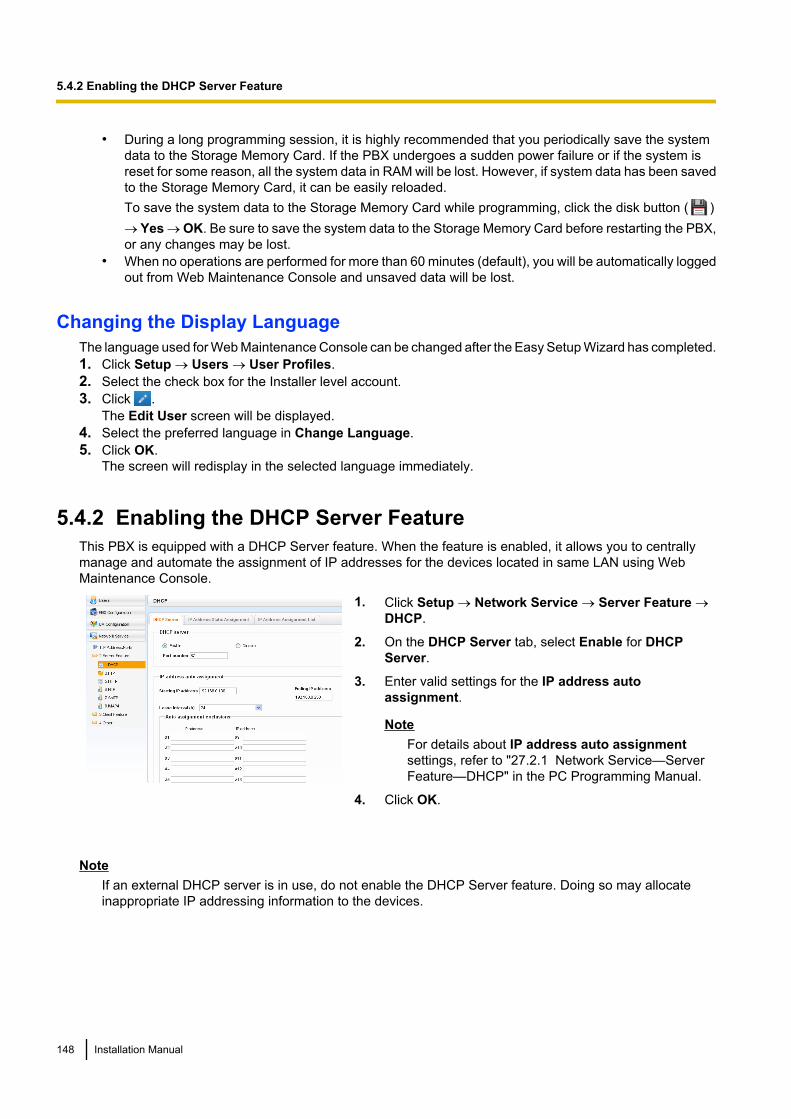
• During a long programming session, it is highly recommended that you periodically save the systemdata to the Storage Memory Card. If the PBX undergoes a sudden power failure or if the system isreset for some reason, all the system data in RAM will be lost. However, if system data has been savedto the Storage Memory Card, it can be easily reloaded.To save the system data to the Storage Memory Card while programming, click the disk button ( )® Yes ® OK. Be sure to save the system data to the Storage Memory Card before restarting the PBX,or any changes may be lost.
• When no operations are performed for more than 60 minutes (default), you will be automatically loggedout from Web Maintenance Console and unsaved data will be lost.
Changing the Display LanguageThe language used for Web Maintenance Console can be changed after the Easy Setup Wizard has completed.1. Click Setup ® Users ® User Profiles.2. Select the check box for the Installer level account.3. Click .
The Edit User screen will be displayed.4. Select the preferred language in Change Language.5. Click OK.
The screen will redisplay in the selected language immediately.
5.4.2 Enabling the DHCP Server FeatureThis PBX is equipped with a DHCP Server feature. When the feature is enabled, it allows you to centrallymanage and automate the assignment of IP addresses for the devices located in same LAN using WebMaintenance Console.
1. Click Setup ® Network Service ® Server Feature ®DHCP.
2. On the DHCP Server tab, select Enable for DHCPServer.
3. Enter valid settings for the IP address autoassignment.
NoteFor details about IP address auto assignmentsettings, refer to "27.2.1 Network Service—ServerFeature—DHCP" in the PC Programming Manual.
4. Click OK.
NoteIf an external DHCP server is in use, do not enable the DHCP Server feature. Doing so may allocateinappropriate IP addressing information to the devices.
148 Installation Manual
5.4.2 Enabling the DHCP Server Feature
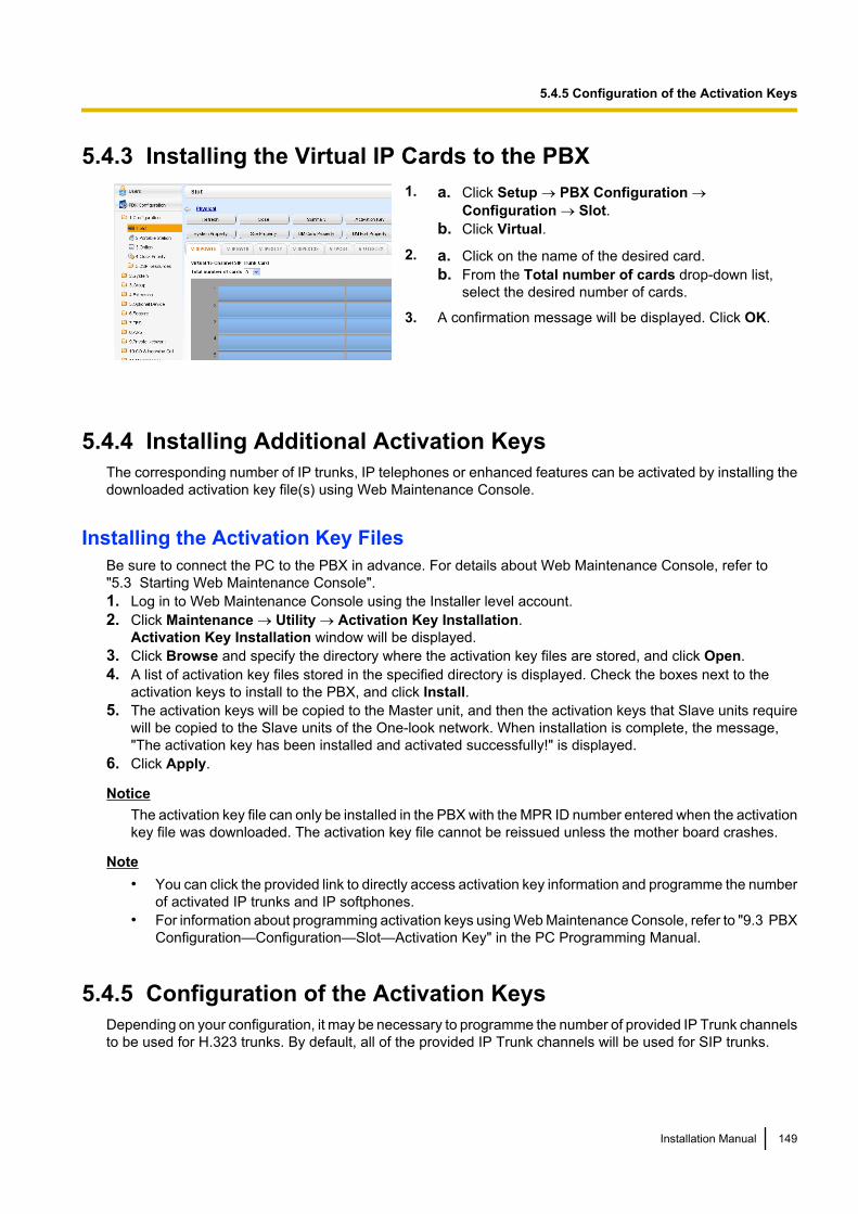
5.4.3 Installing the Virtual IP Cards to the PBX1. a. Click Setup ® PBX Configuration ®
Configuration ® Slot.b. Click Virtual.
2. a. Click on the name of the desired card.b. From the Total number of cards drop-down list,
select the desired number of cards.
3. A confirmation message will be displayed. Click OK.
5.4.4 Installing Additional Activation KeysThe corresponding number of IP trunks, IP telephones or enhanced features can be activated by installing thedownloaded activation key file(s) using Web Maintenance Console.
Installing the Activation Key FilesBe sure to connect the PC to the PBX in advance. For details about Web Maintenance Console, refer to"5.3 Starting Web Maintenance Console".1. Log in to Web Maintenance Console using the Installer level account.2. Click Maintenance ® Utility ® Activation Key Installation.
Activation Key Installation window will be displayed.3. Click Browse and specify the directory where the activation key files are stored, and click Open.4. A list of activation key files stored in the specified directory is displayed. Check the boxes next to the
activation keys to install to the PBX, and click Install.5. The activation keys will be copied to the Master unit, and then the activation keys that Slave units require
will be copied to the Slave units of the One-look network. When installation is complete, the message,"The activation key has been installed and activated successfully!" is displayed.
6. Click Apply.
NoticeThe activation key file can only be installed in the PBX with the MPR ID number entered when the activationkey file was downloaded. The activation key file cannot be reissued unless the mother board crashes.
Note• You can click the provided link to directly access activation key information and programme the number
of activated IP trunks and IP softphones.• For information about programming activation keys using Web Maintenance Console, refer to "9.3 PBX
Configuration—Configuration—Slot—Activation Key" in the PC Programming Manual.
5.4.5 Configuration of the Activation KeysDepending on your configuration, it may be necessary to programme the number of provided IP Trunk channelsto be used for H.323 trunks. By default, all of the provided IP Trunk channels will be used for SIP trunks.
Installation Manual 149
5.4.5 Configuration of the Activation Keys
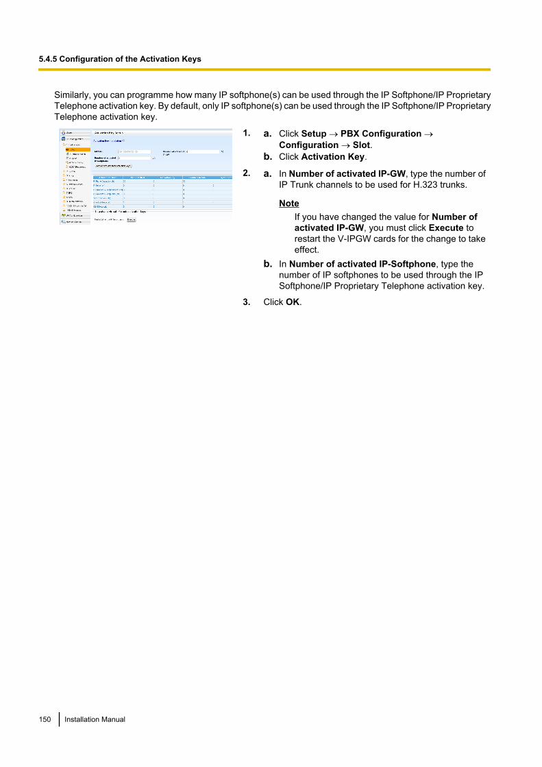
Similarly, you can programme how many IP softphone(s) can be used through the IP Softphone/IP ProprietaryTelephone activation key. By default, only IP softphone(s) can be used through the IP Softphone/IP ProprietaryTelephone activation key.
1. a. Click Setup ® PBX Configuration ®Configuration ® Slot.
b. Click Activation Key.
2. a. In Number of activated IP-GW, type the number ofIP Trunk channels to be used for H.323 trunks.
NoteIf you have changed the value for Number ofactivated IP-GW, you must click Execute torestart the V-IPGW cards for the change to takeeffect.
b. In Number of activated IP-Softphone, type thenumber of IP softphones to be used through the IPSoftphone/IP Proprietary Telephone activation key.
3. Click OK.
150 Installation Manual
5.4.5 Configuration of the Activation Keys
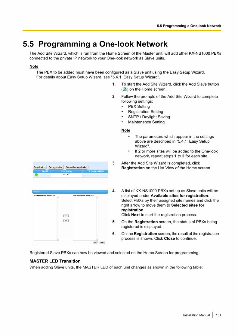
5.5 Programming a One-look NetworkThe Add Site Wizard, which is run from the Home Screen of the Master unit, will add other KX-NS1000 PBXsconnected to the private IP network to your One-look network as Slave units.
NoteThe PBX to be added must have been configured as a Slave unit using the Easy Setup Wizard.For details about Easy Setup Wizard, see "5.4.1 Easy Setup Wizard".
1. To start the Add Site Wizard, click the Add Slave button( ) on the Home screen.
2. Follow the prompts of the Add Site Wizard to completefollowing settings:• PBX Setting• Registration Setting• SNTP / Daylight Saving• Maintenance Setting
Note• The parameters which appear in the settings
above are described in "5.4.1 Easy SetupWizard".
• If 2 or more sites will be added to the One-looknetwork, repeat steps 1 to 2 for each site.
3. After the Add Site Wizard is completed, clickRegistration on the List View of the Home screen.
4. A list of KX-NS1000 PBXs set up as Slave units will bedisplayed under Available sites for registration.Select PBXs by their assigned site names and click theright arrow to move them to Selected sites forregistration.Click Next to start the registration process.
5. On the Registration screen, the status of PBXs beingregistered is displayed.
6. On the Registration screen, the result of the registrationprocess is shown. Click Close to continue.
Registered Slave PBXs can now be viewed and selected on the Home Screen for programming.
MASTER LED TransitionWhen adding Slave units, the MASTER LED of each unit changes as shown in the following table:
Installation Manual 151
5.5 Programming a One-look Network
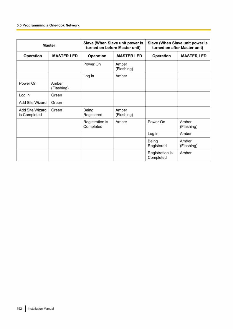
Master Slave (When Slave unit power isturned on before Master unit)
Slave (When Slave unit power isturned on after Master unit)
Operation MASTER LED Operation MASTER LED Operation MASTER LED
Power On Amber(Flashing)
Log in Amber
Power On Amber(Flashing)
Log in Green
Add Site Wizard Green
Add Site Wizardis Completed
Green BeingRegistered
Amber(Flashing)
Registration isCompleted
Amber Power On Amber(Flashing)
Log in Amber
BeingRegistered
Amber(Flashing)
Registration isCompleted
Amber
152 Installation Manual
5.5 Programming a One-look Network
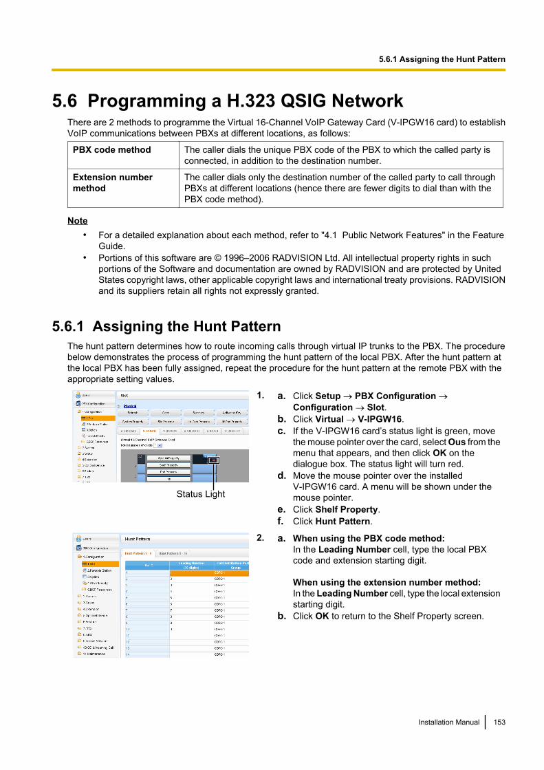
5.6 Programming a H.323 QSIG NetworkThere are 2 methods to programme the Virtual 16-Channel VoIP Gateway Card (V-IPGW16 card) to establishVoIP communications between PBXs at different locations, as follows:
PBX code method The caller dials the unique PBX code of the PBX to which the called party isconnected, in addition to the destination number.
Extension number method
The caller dials only the destination number of the called party to call throughPBXs at different locations (hence there are fewer digits to dial than with thePBX code method).
Note• For a detailed explanation about each method, refer to "4.1 Public Network Features" in the Feature
Guide.• Portions of this software are © 1996–2006 RADVISION Ltd. All intellectual property rights in such
portions of the Software and documentation are owned by RADVISION and are protected by UnitedStates copyright laws, other applicable copyright laws and international treaty provisions. RADVISIONand its suppliers retain all rights not expressly granted.
5.6.1 Assigning the Hunt PatternThe hunt pattern determines how to route incoming calls through virtual IP trunks to the PBX. The procedurebelow demonstrates the process of programming the hunt pattern of the local PBX. After the hunt pattern atthe local PBX has been fully assigned, repeat the procedure for the hunt pattern at the remote PBX with theappropriate setting values.
Status Light
1. a. Click Setup ® PBX Configuration ®Configuration ® Slot.
b. Click Virtual ® V-IPGW16.c. If the V-IPGW16 card’s status light is green, move
the mouse pointer over the card, select Ous from themenu that appears, and then click OK on thedialogue box. The status light will turn red.
d. Move the mouse pointer over the installedV-IPGW16 card. A menu will be shown under themouse pointer.
e. Click Shelf Property.f. Click Hunt Pattern.
2. a. When using the PBX code method:In the Leading Number cell, type the local PBXcode and extension starting digit.
When using the extension number method:In the Leading Number cell, type the local extensionstarting digit.
b. Click OK to return to the Shelf Property screen.
Installation Manual 153
5.6.1 Assigning the Hunt Pattern
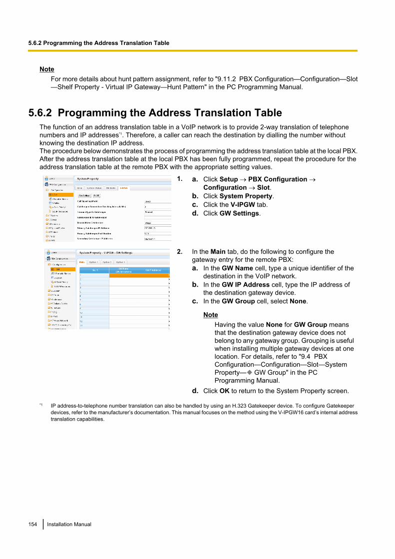
NoteFor more details about hunt pattern assignment, refer to "9.11.2 PBX Configuration—Configuration—Slot—Shelf Property - Virtual IP Gateway—Hunt Pattern" in the PC Programming Manual.
5.6.2 Programming the Address Translation TableThe function of an address translation table in a VoIP network is to provide 2-way translation of telephonenumbers and IP addresses*1. Therefore, a caller can reach the destination by dialling the number withoutknowing the destination IP address.The procedure below demonstrates the process of programming the address translation table at the local PBX.After the address translation table at the local PBX has been fully programmed, repeat the procedure for theaddress translation table at the remote PBX with the appropriate setting values.
1. a. Click Setup ® PBX Configuration ®Configuration ® Slot.
b. Click System Property.c. Click the V-IPGW tab.d. Click GW Settings.
2. In the Main tab, do the following to configure thegateway entry for the remote PBX:a. In the GW Name cell, type a unique identifier of the
destination in the VoIP network.b. In the GW IP Address cell, type the IP address of
the destination gateway device.c. In the GW Group cell, select None.
NoteHaving the value None for GW Group meansthat the destination gateway device does notbelong to any gateway group. Grouping is usefulwhen installing multiple gateway devices at onelocation. For details, refer to "9.4 PBXConfiguration—Configuration—Slot—SystemProperty— GW Group" in the PCProgramming Manual.
d. Click OK to return to the System Property screen.
*1 IP address-to-telephone number translation can also be handled by using an H.323 Gatekeeper device. To configure Gatekeeperdevices, refer to the manufacturer’s documentation. This manual focuses on the method using the V-IPGW16 card’s internal addresstranslation capabilities.
154 Installation Manual
5.6.2 Programming the Address Translation Table
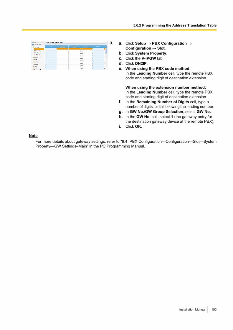
3. a. Click Setup ® PBX Configuration ®Configuration ® Slot.
b. Click System Property.c. Click the V-IPGW tab.d. Click DN2IP.e. When using the PBX code method:
In the Leading Number cell, type the remote PBXcode and starting digit of destination extension.
When using the extension number method:In the Leading Number cell, type the remote PBXcode and starting digit of destination extension.
f. In the Remaining Number of Digits cell, type anumber of digits to dial following the leading number.
g. In GW No./GW Group Selection, select GW No.h. In the GW No. cell, select 1 (the gateway entry for
the destination gateway device at the remote PBX).i. Click OK.
NoteFor more details about gateway settings, refer to "9.4 PBX Configuration—Configuration—Slot—SystemProperty—GW Settings–Main" in the PC Programming Manual.
Installation Manual 155
5.6.2 Programming the Address Translation Table
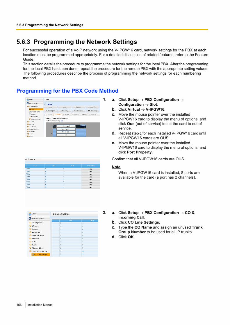
5.6.3 Programming the Network SettingsFor successful operation of a VoIP network using the V-IPGW16 card, network settings for the PBX at eachlocation must be programmed appropriately. For a detailed discussion of related features, refer to the FeatureGuide.This section details the procedure to programme the network settings for the local PBX. After the programmingfor the local PBX has been done, repeat the procedure for the remote PBX with the appropriate setting values.The following procedures describe the process of programming the network settings for each numberingmethod.
Programming for the PBX Code Method1. a. Click Setup ® PBX Configuration ®
Configuration ® Slot.b. Click Virtual ® V-IPGW16.c. Move the mouse pointer over the installed
V-IPGW16 card to display the menu of options, andclick Ous (out of service) to set the card to out ofservice.
d. Repeat step c for each installed V-IPGW16 card untilall V-IPGW16 cards are OUS.
e. Move the mouse pointer over the installedV-IPGW16 card to display the menu of options, andclick Port Property.
Confirm that all V-IPGW16 cards are OUS.
NoteWhen a V-IPGW16 card is installed, 8 ports areavailable for the card (a port has 2 channels).
2. a. Click Setup ® PBX Configuration ® CO &Incoming Call.
b. Click CO Line Settings.c. Type the CO Name and assign an unused Trunk
Group Number to be used for all IP trunks.d. Click OK.
156 Installation Manual
5.6.3 Programming the Network Settings
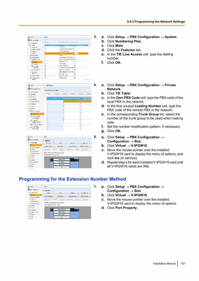
3. a. Click Setup ® PBX Configuration ® System.b. Click Numbering Plan.c. Click Main.d. Click the Features tab.e. In the TIE Line Access cell, type the dialling
number.f. Click OK.
4. a. Click Setup ® PBX Configuration ® PrivateNetwork.
b. Click TIE Table.c. In the Own PBX Code cell, type the PBX code of the
local PBX in the network.d. In the first unused Leading Number cell, type the
PBX code of the remote PBX in the network.e. In the corresponding Trunk Group list, select the
number of the trunk group to be used when makingcalls.
f. Set the number modification pattern, if necessary.g. Click OK.
5. a. Click Setup ® PBX Configuration ®Configuration ® Slot.
b. Click Virtual ® V-IPGW16.c. Move the mouse pointer over the installed
V-IPGW16 card to display the menu of options, andclick Ins (in service).
d. Repeat step c for each installed V-IPGW16 card untilall V-IPGW16 cards are INS.
Programming for the Extension Number Method1. a. Click Setup ® PBX Configuration ®
Configuration ® Slot.b. Click Virtual ® V-IPGW16.c. Move the mouse pointer over the installed
V-IPGW16 card to display the menu of options.d. Click Port Property.
Installation Manual 157
5.6.3 Programming the Network Settings
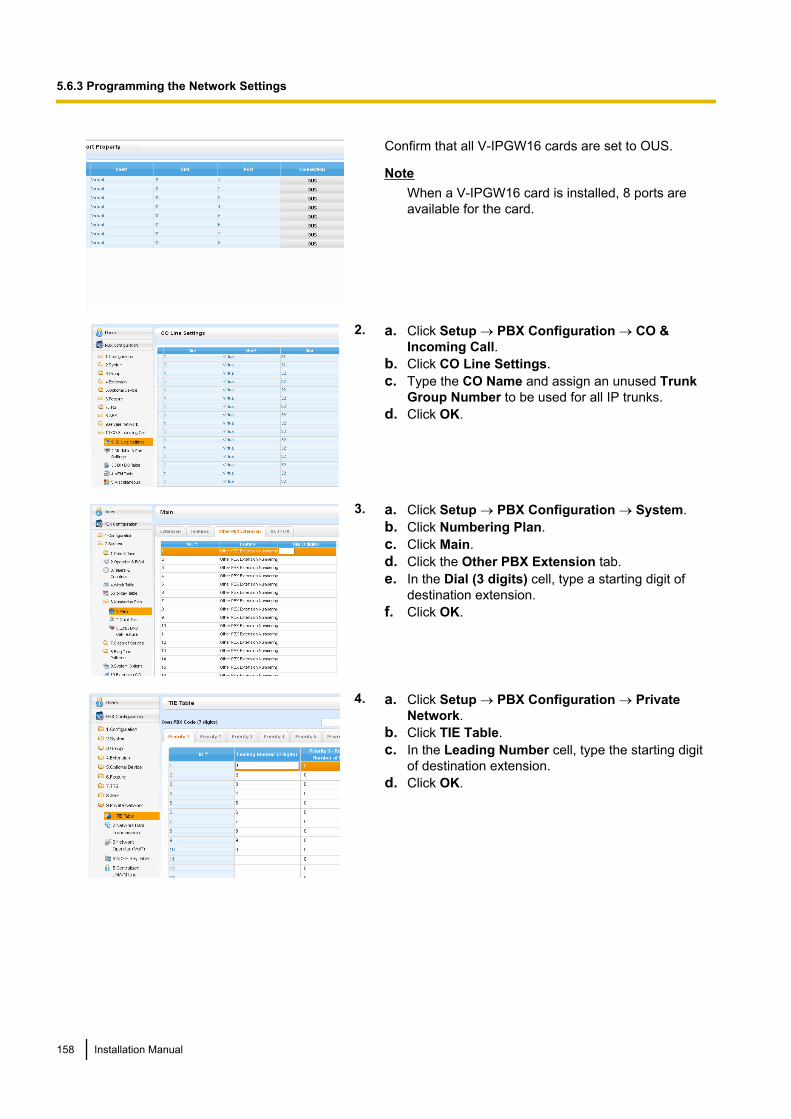
Confirm that all V-IPGW16 cards are set to OUS.
NoteWhen a V-IPGW16 card is installed, 8 ports areavailable for the card.
2. a. Click Setup ® PBX Configuration ® CO &Incoming Call.
b. Click CO Line Settings.c. Type the CO Name and assign an unused Trunk
Group Number to be used for all IP trunks.d. Click OK.
3. a. Click Setup ® PBX Configuration ® System.b. Click Numbering Plan.c. Click Main.d. Click the Other PBX Extension tab.e. In the Dial (3 digits) cell, type a starting digit of
destination extension.f. Click OK.
4. a. Click Setup ® PBX Configuration ® PrivateNetwork.
b. Click TIE Table.c. In the Leading Number cell, type the starting digit
of destination extension.d. Click OK.
158 Installation Manual
5.6.3 Programming the Network Settings
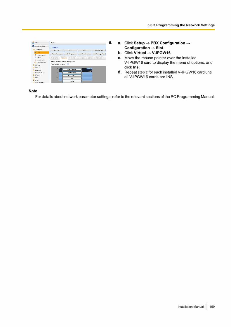
5. a. Click Setup ® PBX Configuration ®Configuration ® Slot.
b. Click Virtual ® V-IPGW16.c. Move the mouse pointer over the installed
V-IPGW16 card to display the menu of options, andclick Ins.
d. Repeat step c for each installed V-IPGW16 card untilall V-IPGW16 cards are INS.
NoteFor details about network parameter settings, refer to the relevant sections of the PC Programming Manual.
Installation Manual 159
5.6.3 Programming the Network Settings
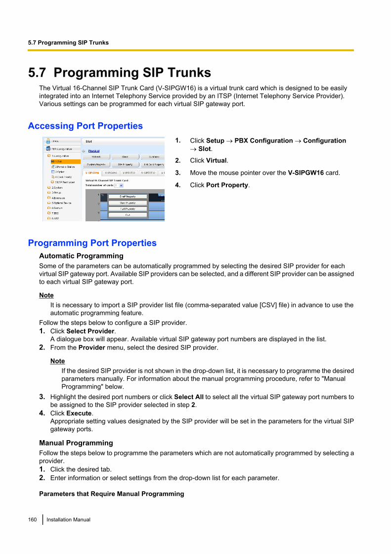
5.7 Programming SIP TrunksThe Virtual 16-Channel SIP Trunk Card (V-SIPGW16) is a virtual trunk card which is designed to be easilyintegrated into an Internet Telephony Service provided by an ITSP (Internet Telephony Service Provider).Various settings can be programmed for each virtual SIP gateway port.
Accessing Port Properties1. Click Setup ® PBX Configuration ® Configuration
® Slot.
2. Click Virtual.
3. Move the mouse pointer over the V-SIPGW16 card.
4. Click Port Property.
Programming Port PropertiesAutomatic ProgrammingSome of the parameters can be automatically programmed by selecting the desired SIP provider for eachvirtual SIP gateway port. Available SIP providers can be selected, and a different SIP provider can be assignedto each virtual SIP gateway port.
NoteIt is necessary to import a SIP provider list file (comma-separated value [CSV] file) in advance to use theautomatic programming feature.
Follow the steps below to configure a SIP provider.1. Click Select Provider.
A dialogue box will appear. Available virtual SIP gateway port numbers are displayed in the list.2. From the Provider menu, select the desired SIP provider.
NoteIf the desired SIP provider is not shown in the drop-down list, it is necessary to programme the desiredparameters manually. For information about the manual programming procedure, refer to "ManualProgramming" below.
3. Highlight the desired port numbers or click Select All to select all the virtual SIP gateway port numbers tobe assigned to the SIP provider selected in step 2.
4. Click Execute.Appropriate setting values designated by the SIP provider will be set in the parameters for the virtual SIPgateway ports.
Manual ProgrammingFollow the steps below to programme the parameters which are not automatically programmed by selecting aprovider.1. Click the desired tab.2. Enter information or select settings from the drop-down list for each parameter.
Parameters that Require Manual Programming
160 Installation Manual
5.7 Programming SIP Trunks
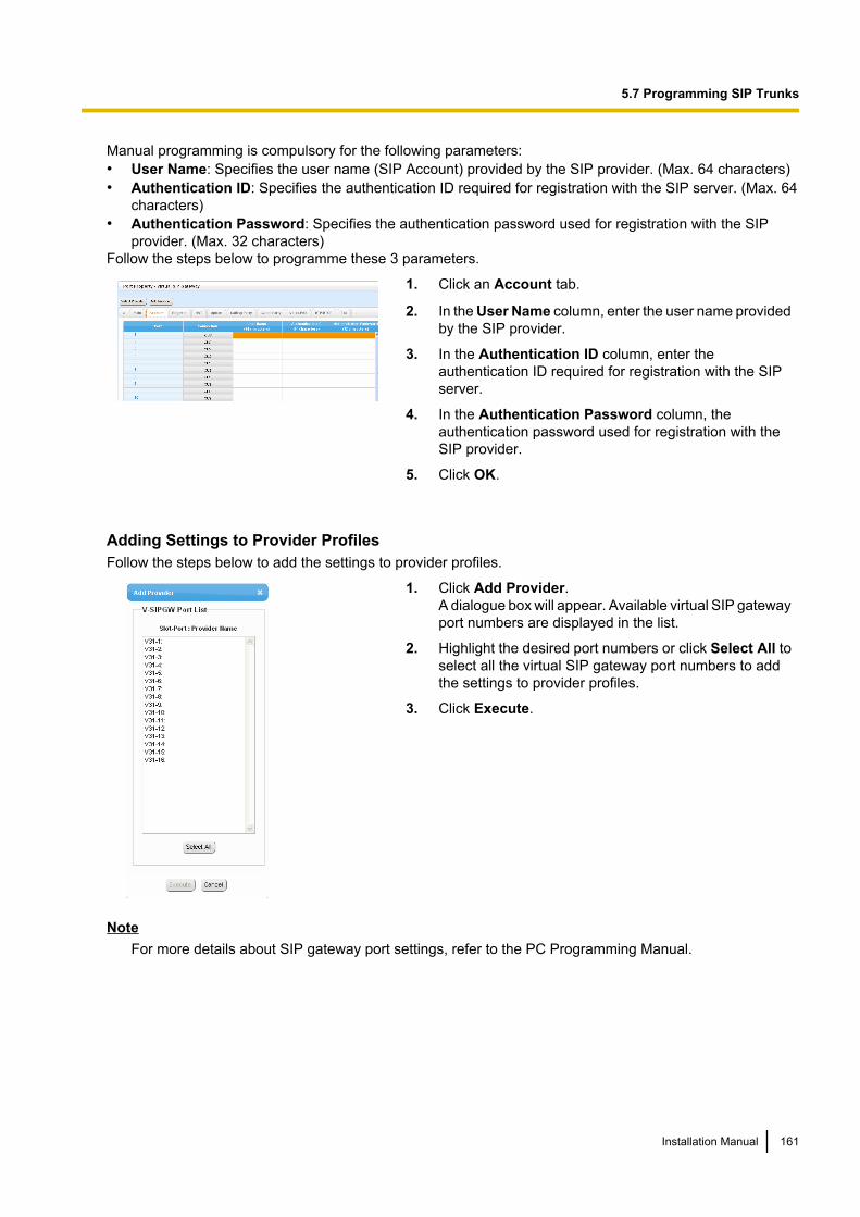
Manual programming is compulsory for the following parameters:• User Name: Specifies the user name (SIP Account) provided by the SIP provider. (Max. 64 characters)• Authentication ID: Specifies the authentication ID required for registration with the SIP server. (Max. 64
characters)• Authentication Password: Specifies the authentication password used for registration with the SIP
provider. (Max. 32 characters)Follow the steps below to programme these 3 parameters.
1. Click an Account tab.
2. In the User Name column, enter the user name providedby the SIP provider.
3. In the Authentication ID column, enter theauthentication ID required for registration with the SIPserver.
4. In the Authentication Password column, theauthentication password used for registration with theSIP provider.
5. Click OK.
Adding Settings to Provider ProfilesFollow the steps below to add the settings to provider profiles.
1. Click Add Provider.A dialogue box will appear. Available virtual SIP gatewayport numbers are displayed in the list.
2. Highlight the desired port numbers or click Select All toselect all the virtual SIP gateway port numbers to addthe settings to provider profiles.
3. Click Execute.
NoteFor more details about SIP gateway port settings, refer to the PC Programming Manual.
Installation Manual 161
5.7 Programming SIP Trunks
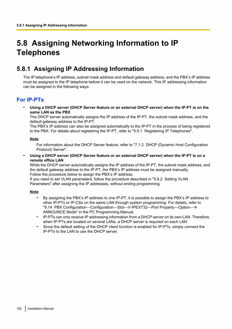
5.8 Assigning Networking Information to IPTelephones
5.8.1 Assigning IP Addressing InformationThe IP telephone’s IP address, subnet mask address and default gateway address, and the PBX’s IP addressmust be assigned to the IP telephone before it can be used on the network. This IP addressing informationcan be assigned in the following ways:
For IP-PTs• Using a DHCP server (DHCP Server feature or an external DHCP server) when the IP-PT is on the
same LAN as the PBXThe DHCP server automatically assigns the IP address of the IP-PT, the subnet mask address, and thedefault gateway address to the IP-PT.The PBX’s IP address can also be assigned automatically to the IP-PT in the process of being registeredto the PBX. For details about registering the IP-PT, refer to "5.9.1 Registering IP Telephones".
NoteFor information about the DHCP Server feature, refer to "7.1.2 DHCP (Dynamic Host ConfigurationProtocol) Server".
• Using a DHCP server (DHCP Server feature or an external DHCP server) when the IP-PT is on aremote office LANWhile the DHCP server automatically assigns the IP address of the IP-PT, the subnet mask address, andthe default gateway address to the IP-PT, the PBX’s IP address must be assigned manually.Follow the procedure below to assign the PBX’s IP address.If you need to set VLAN parameters, follow the procedure described in "5.8.2 Setting VLANParameters" after assigning the IP addresses, without ending programming.
Note• By assigning the PBX’s IP address to one IP-PT, it is possible to assign the PBX’s IP address to
other IP-PTs or IP-CSs on the same LAN through system programming. For details, refer to"9.14 PBX Configuration—Configuration—Slot—V-IPEXT32—Port Property—Option—ANNOUNCE Mode" in the PC Programming Manual.
• IP-PTs can only receive IP addressing information from a DHCP server on its own LAN. Therefore,when IP-PTs are located on several LANs, a DHCP server is required on each LAN.
• Since the default setting of the DHCP client function is enabled for IP-PTs, simply connect theIP-PTs to the LAN to use the DHCP server.
162 Installation Manual
5.8.1 Assigning IP Addressing Information
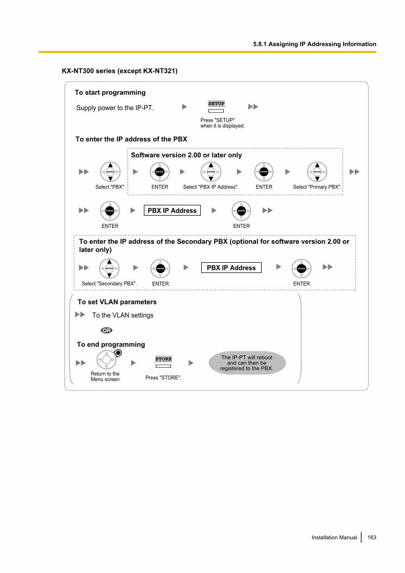
KX-NT300 series (except KX-NT321)
PBX IP Address
ENTER ENTER
Select "PBX". Select "PBX IP Address". Select "Primary PBX".ENTER ENTER
To enter the IP address of the PBX
Press "SETUP" when it is displayed.
SETUP
To start programming
Supply power to the IP-PT.
To enter the IP address of the Secondary PBX (optional for software version 2.00 or
later only)
PBX IP Address
Software version 2.00 or later only
Select "Secondary PBX". ENTER ENTER
To the VLAN settings
Press "STORE".
To end programming
To set VLAN parameters
OR
The IP-PT will reboot and can then be
registered to the PBX.
STORE
Return to the Menu screen.
Installation Manual 163
5.8.1 Assigning IP Addressing Information
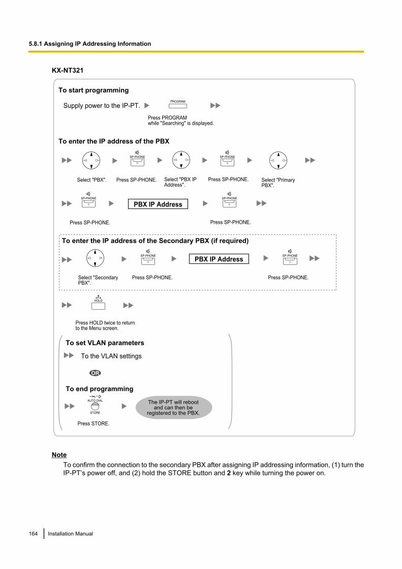
KX-NT321
Press PROGRAMwhile "Searching" is displayed.
To start programming
Supply power to the IP-PT.
To enter the IP address of the PBX
To the VLAN settings
The IP-PT will reboot and can then be
registered to the PBX.
To end programming
To set VLAN parameters
OR
Press HOLD twice to returnto the Menu screen.
Select "PBX IP Address".
Press SP-PHONE.
Press SP-PHONE.
Press STORE.
Select "PBX". Press SP-PHONE.
Press SP-PHONE.
Select "Primary PBX".
Press SP-PHONE.
Select "Secondary PBX".
Press SP-PHONE.
To enter the IP address of the Secondary PBX (if required)
PBX IP Address
PBX IP Address
NoteTo confirm the connection to the secondary PBX after assigning IP addressing information, (1) turn theIP-PT’s power off, and (2) hold the STORE button and 2 key while turning the power on.
164 Installation Manual
5.8.1 Assigning IP Addressing Information
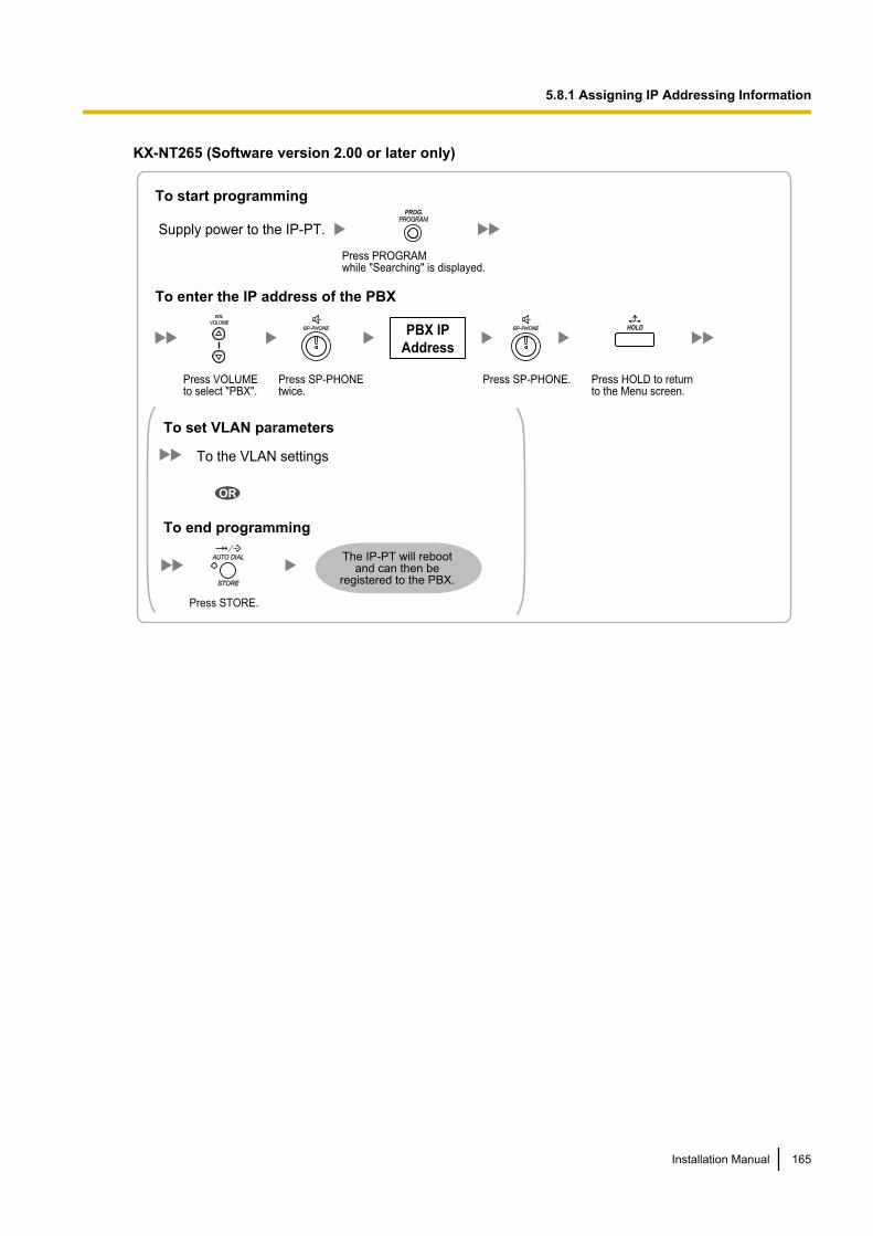
KX-NT265 (Software version 2.00 or later only)
PBX IP
Address
To enter the IP address of the PBX
Press PROGRAMwhile "Searching" is displayed.
To start programming
Supply power to the IP-PT.
PROG.
Press HOLD to return to the Menu screen.
HOLD
Press VOLUME to select "PBX".
VOL
Press SP-PHONEtwice.
Press SP-PHONE.
To the VLAN settings
The IP-PT will reboot and can then be
registered to the PBX.
To end programming
To set VLAN parameters
OR
Press STORE.
Installation Manual 165
5.8.1 Assigning IP Addressing Information
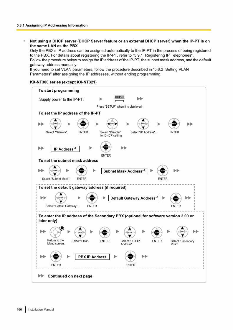
• Not using a DHCP server (DHCP Server feature or an external DHCP server) when the IP-PT is onthe same LAN as the PBXOnly the PBX’s IP address can be assigned automatically to the IP-PT in the process of being registeredto the PBX. For details about registering the IP-PT, refer to "5.9.1 Registering IP Telephones".Follow the procedure below to assign the IP address of the IP-PT, the subnet mask address, and the defaultgateway address manually.If you need to set VLAN parameters, follow the procedure described in "5.8.2 Setting VLANParameters" after assigning the IP addresses, without ending programming.
KX-NT300 series (except KX-NT321)
Select "Network". ENTER Select "Disable" for DHCP setting.
ENTER
IP Address*1
ENTER
To set the IP address of the IP-PT
Select "Default Gateway". ENTER
Default Gateway Address*3
ENTER
To set the default gateway address (if required)
To set the subnet mask address
Select "Subnet Mask". ENTER
Subnet Mask Address*2
ENTER
Select "IP Address".
To start programming
Press "SETUP" when it is displayed.
SETUPSupply power to the IP-PT.
Return to the Menu screen.
To enter the IP address of the Secondary PBX (optional for software version 2.00 or
later only)
PBX IP Address
ENTER ENTER
Select "PBX". Select "PBX IP Address".
ENTER ENTER Select "Secondary PBX".
Continued on next page
166 Installation Manual
5.8.1 Assigning IP Addressing Information
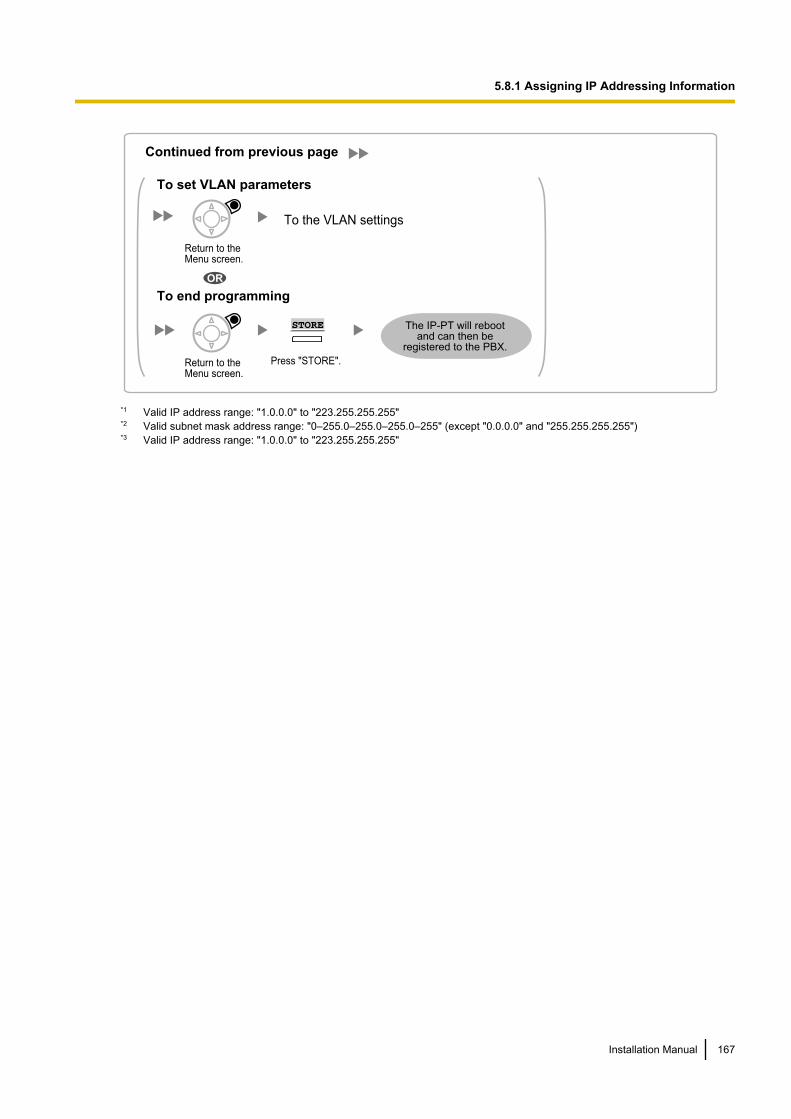
To the VLAN settings
Press "STORE".
STORE
To end programming
To set VLAN parameters
OR
The IP-PT will reboot and can then be
registered to the PBX.
Return to the Menu screen.
Return to the Menu screen.
Continued from previous page
*1 Valid IP address range: "1.0.0.0" to "223.255.255.255"*2 Valid subnet mask address range: "0–255.0–255.0–255.0–255" (except "0.0.0.0" and "255.255.255.255")*3 Valid IP address range: "1.0.0.0" to "223.255.255.255"
Installation Manual 167
5.8.1 Assigning IP Addressing Information
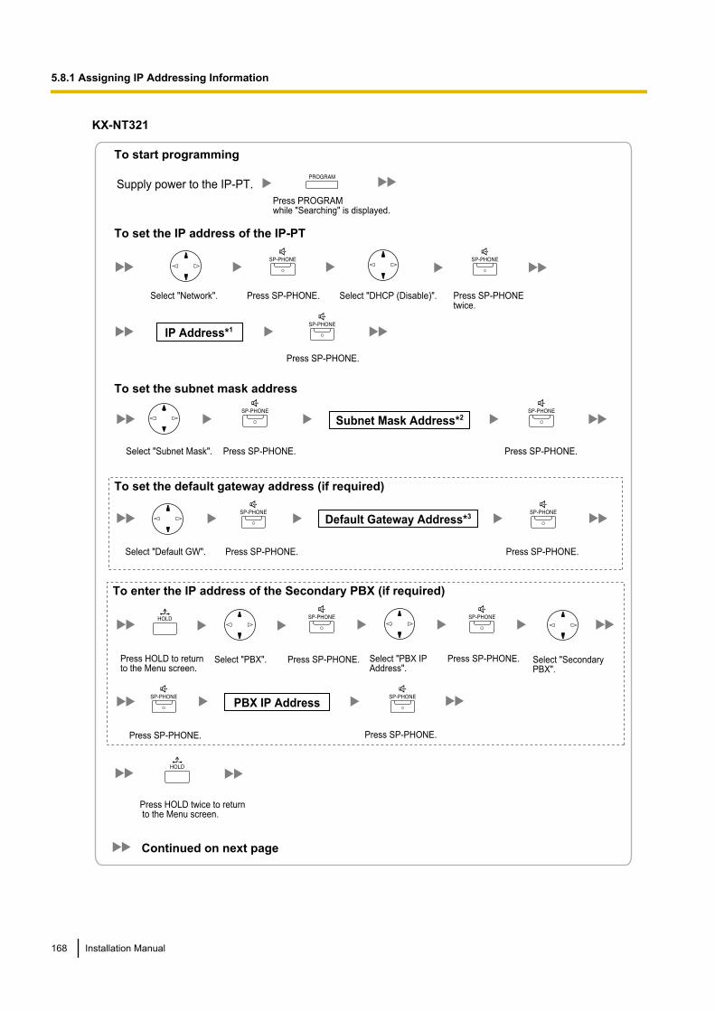
KX-NT321
IP Address*1
Subnet Mask Address*2
Default Gateway Address*3
To set the IP address of the IP-PT
To set the subnet mask address
To set the default gateway address (if required)
To start programming
Supply power to the IP-PT.
Press PROGRAMwhile "Searching" is displayed.
Select "Network". Press SP-PHONE. Select "DHCP (Disable)". Press SP-PHONEtwice.
Press SP-PHONE.
Select "Subnet Mask". Press SP-PHONE. Press SP-PHONE.
Select "Default GW". Press SP-PHONE. Press SP-PHONE.
Press HOLD to return to the Menu screen.
To enter the IP address of the Secondary PBX (if required)
Select "PBX IP Address".
Press SP-PHONE.Select "PBX". Press SP-PHONE. Select "Secondary PBX".
Press SP-PHONE. Press SP-PHONE.
PBX IP Address
Press HOLD twice to return to the Menu screen.
Continued on next page
168 Installation Manual
5.8.1 Assigning IP Addressing Information
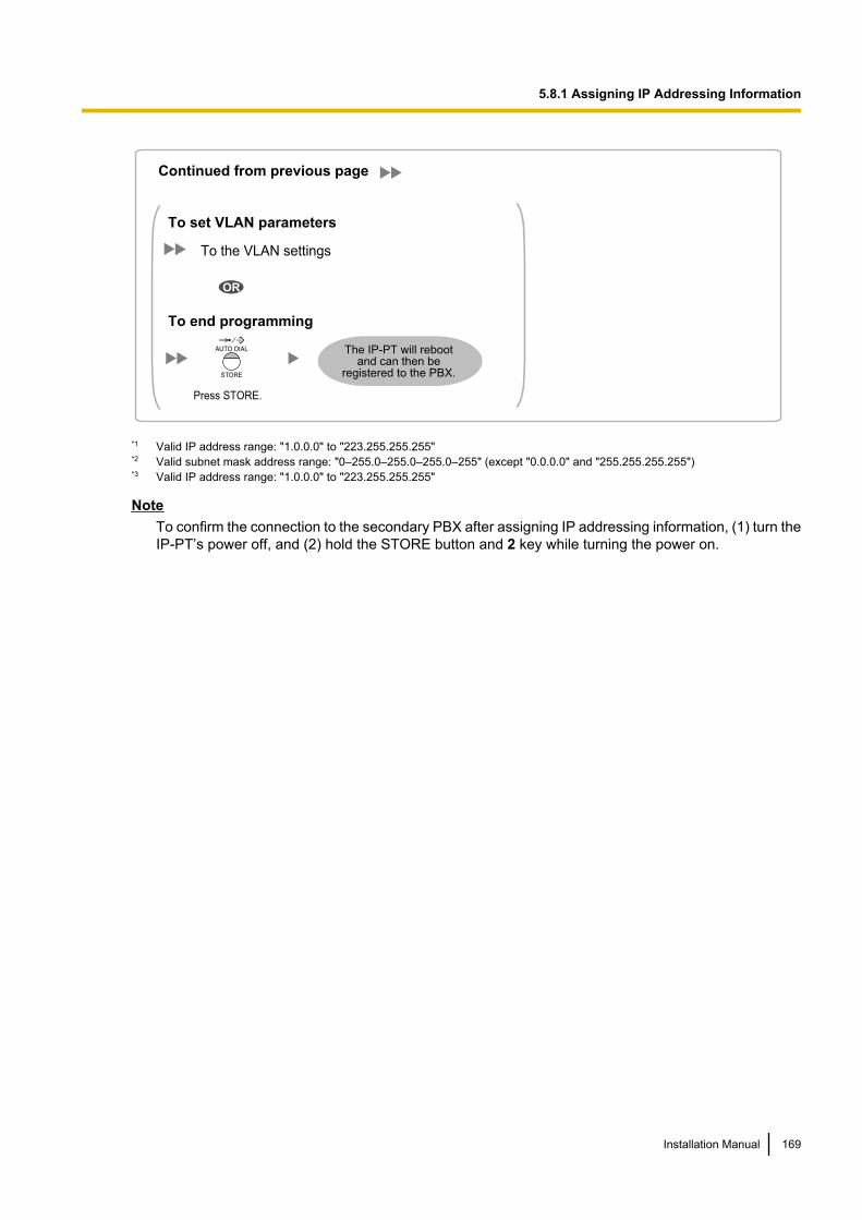
Continued from previous page
To the VLAN settings
The IP-PT will reboot and can then be
registered to the PBX.
To end programming
To set VLAN parameters
OR
Press STORE.
*1 Valid IP address range: "1.0.0.0" to "223.255.255.255"*2 Valid subnet mask address range: "0–255.0–255.0–255.0–255" (except "0.0.0.0" and "255.255.255.255")*3 Valid IP address range: "1.0.0.0" to "223.255.255.255"
NoteTo confirm the connection to the secondary PBX after assigning IP addressing information, (1) turn theIP-PT’s power off, and (2) hold the STORE button and 2 key while turning the power on.
Installation Manual 169
5.8.1 Assigning IP Addressing Information
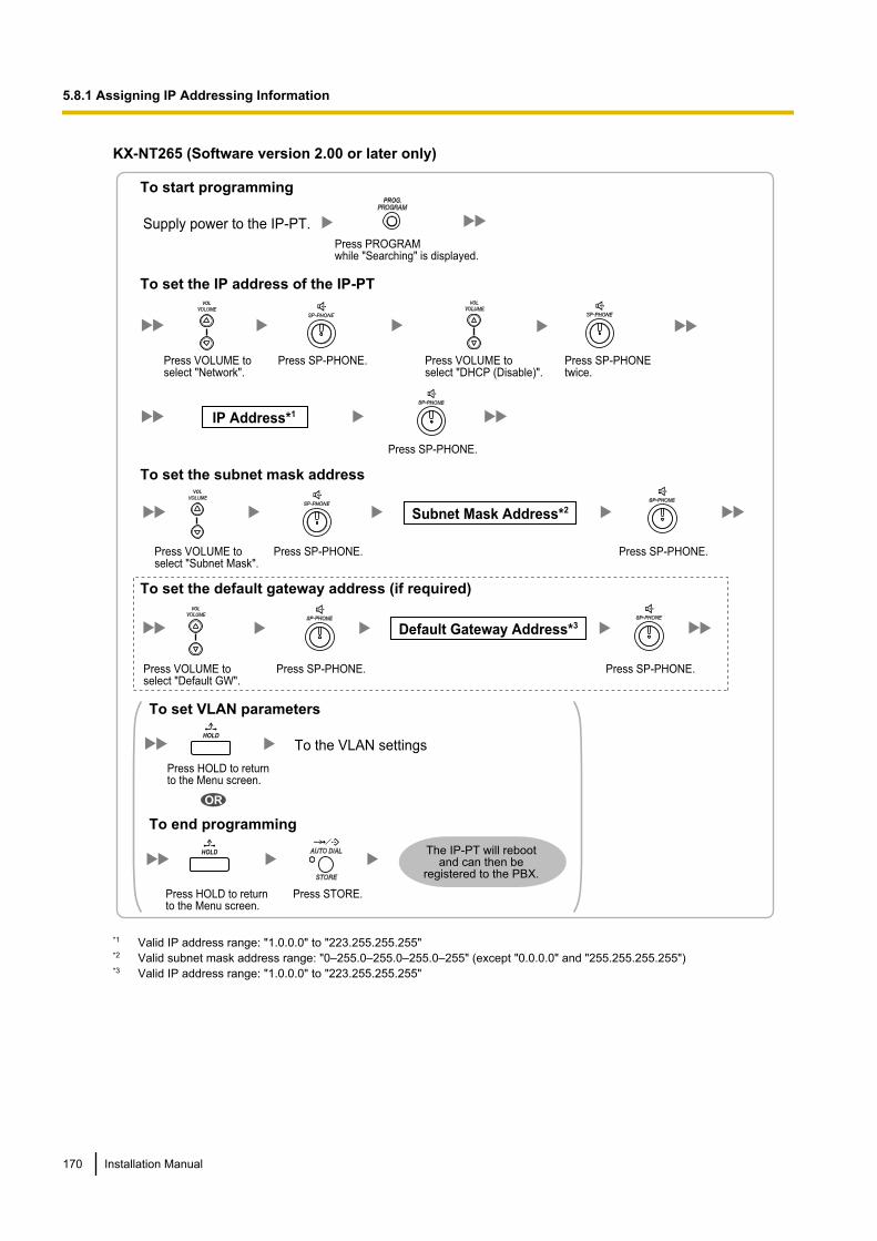
KX-NT265 (Software version 2.00 or later only)
IP Address*1
Subnet Mask Address*2
Default Gateway Address*3
To set the IP address of the IP-PT
To set the subnet mask address
To set the default gateway address (if required)
To start programming
Supply power to the IP-PT.
Press PROGRAMwhile "Searching" is displayed.
PROG.
Press VOLUME toselect "Network".
VOL
Press SP-PHONE. Press VOLUME to select "DHCP (Disable)".
VOL
Press SP-PHONEtwice.
Press SP-PHONE.
Press VOLUME toselect "Subnet Mask".
VOL
Press SP-PHONE. Press SP-PHONE.
Press VOLUME toselect "Default GW".
VOL
Press SP-PHONE. Press SP-PHONE.
To the VLAN settings
The IP-PT will reboot and can then be
registered to the PBX.
To end programming
To set VLAN parameters
OR
Press STORE.Press HOLD to return to the Menu screen.
HOLD
Press HOLD to return to the Menu screen.
HOLD
*1 Valid IP address range: "1.0.0.0" to "223.255.255.255"*2 Valid subnet mask address range: "0–255.0–255.0–255.0–255" (except "0.0.0.0" and "255.255.255.255")*3 Valid IP address range: "1.0.0.0" to "223.255.255.255"
170 Installation Manual
5.8.1 Assigning IP Addressing Information

• Not using a DHCP server (DHCP Server feature or an external DHCP server) when the IP-PT is ona remote office LANAll of the IP addressing information must be assigned manually.Follow the procedure below to assign the IP addressing information.If you need to set VLAN parameters, follow the procedure described in "5.8.2 Setting VLANParameters" after assigning the IP addresses, without ending programming.
NoteBy assigning the PBX’s IP address to one IP-PT, it is possible to assign the PBX’s IP address to otherIP-PTs or IP-CSs on the same LAN through system programming. For details, refer to "9.14 PBXConfiguration—Configuration—Slot—V-IPEXT32—Port Property—Option— ANNOUNCE Mode" inthe PC Programming Manual.
Installation Manual 171
5.8.1 Assigning IP Addressing Information
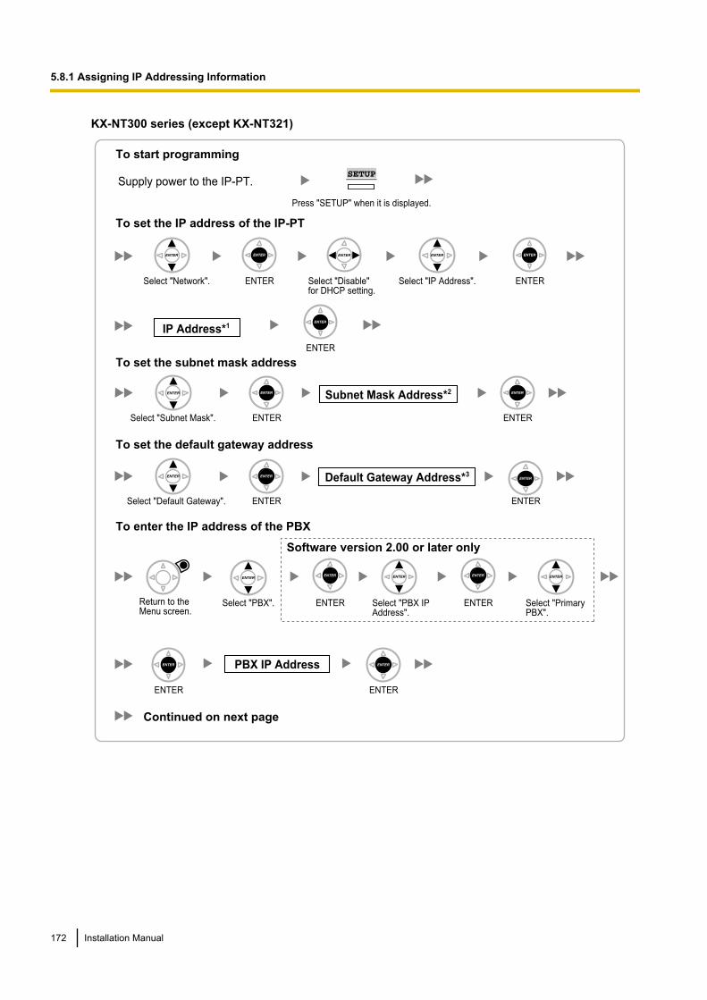
KX-NT300 series (except KX-NT321)
Select "Network". ENTER Select "Disable" for DHCP setting.
ENTER
IP Address*1
ENTER
To set the IP address of the IP-PT
To set the subnet mask address
To set the default gateway address
Select "Default Gateway". ENTER
Default Gateway Address*3
ENTER
ENTER
Subnet Mask Address*2
ENTERSelect "Subnet Mask".
Select "IP Address".
To start programming
Press "SETUP" when it is displayed.
SETUPSupply power to the IP-PT.
Select "PBX".Return to the Menu screen.
PBX IP Address
ENTER ENTER
To enter the IP address of the PBX
Select "PBX IP Address".
Select "Primary PBX".
ENTER ENTER
Software version 2.00 or later only
Continued on next page
172 Installation Manual
5.8.1 Assigning IP Addressing Information
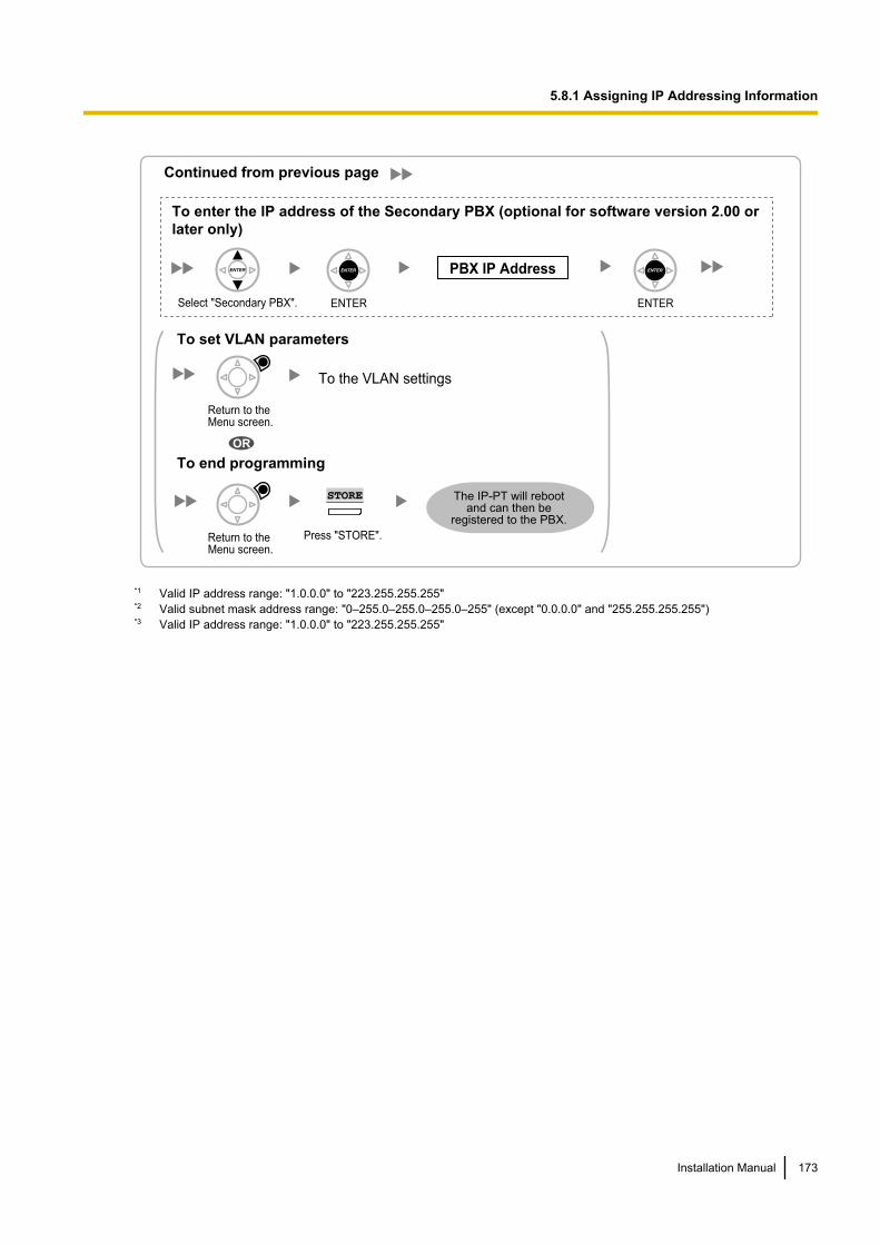
To enter the IP address of the Secondary PBX (optional for software version 2.00 or
later only)
PBX IP Address
Select "Secondary PBX". ENTER ENTER
Continued from previous page
To the VLAN settings
Press "STORE".
STORE
To end programming
To set VLAN parameters
OR
The IP-PT will reboot and can then be
registered to the PBX.
Return to the Menu screen.
Return to the Menu screen.
*1 Valid IP address range: "1.0.0.0" to "223.255.255.255"*2 Valid subnet mask address range: "0–255.0–255.0–255.0–255" (except "0.0.0.0" and "255.255.255.255")*3 Valid IP address range: "1.0.0.0" to "223.255.255.255"
Installation Manual 173
5.8.1 Assigning IP Addressing Information
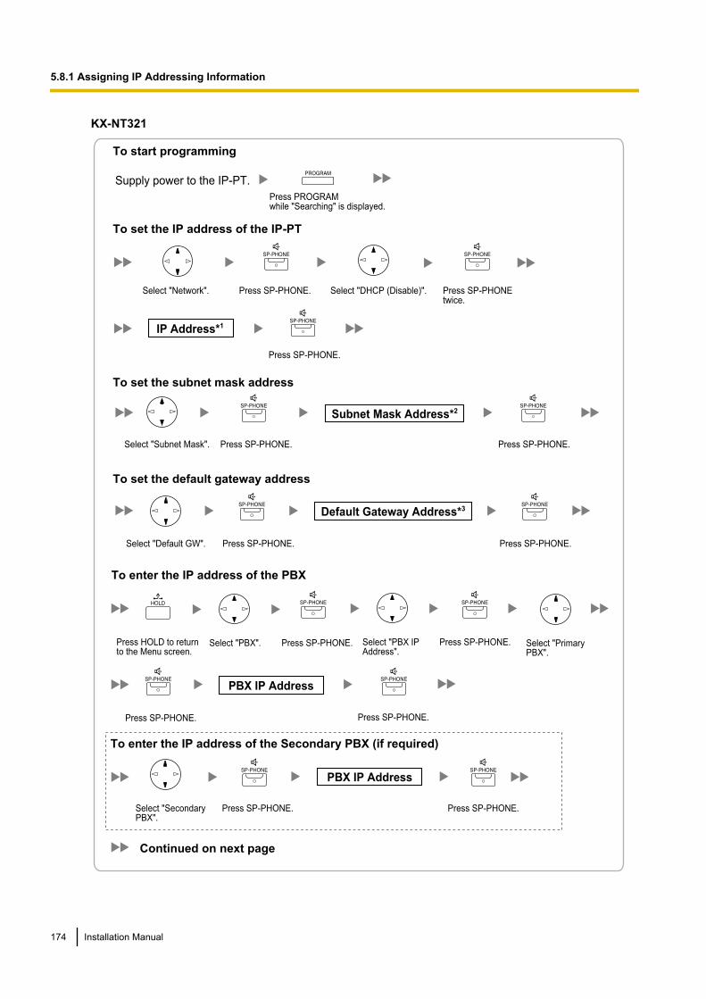
KX-NT321
IP Address*1
Subnet Mask Address*2
Default Gateway Address*3
To set the IP address of the IP-PT
To set the subnet mask address
To set the default gateway address
To start programming
Supply power to the IP-PT.
Press PROGRAMwhile "Searching" is displayed.
Select "Network". Press SP-PHONE. Select "DHCP (Disable)". Press SP-PHONEtwice.
Press SP-PHONE.
Select "Subnet Mask". Press SP-PHONE. Press SP-PHONE.
Select "Default GW". Press SP-PHONE. Press SP-PHONE.
Continued on next page
Press HOLD to return to the Menu screen.
To enter the IP address of the PBX
Select "PBX IP Address".
Press SP-PHONE.Select "PBX". Press SP-PHONE. Select "Primary PBX".
Press SP-PHONE. Press SP-PHONE.
Press SP-PHONE.Select "Secondary PBX".
Press SP-PHONE.
To enter the IP address of the Secondary PBX (if required)
PBX IP Address
PBX IP Address
174 Installation Manual
5.8.1 Assigning IP Addressing Information
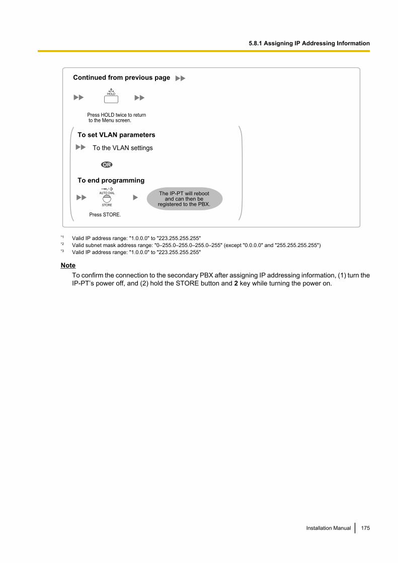
Continued from previous page
To the VLAN settings
The IP-PT will reboot and can then be
registered to the PBX.
To end programming
To set VLAN parameters
OR
Press HOLD twice to return to the Menu screen.
Press STORE.
*1 Valid IP address range: "1.0.0.0" to "223.255.255.255"*2 Valid subnet mask address range: "0–255.0–255.0–255.0–255" (except "0.0.0.0" and "255.255.255.255")*3 Valid IP address range: "1.0.0.0" to "223.255.255.255"
NoteTo confirm the connection to the secondary PBX after assigning IP addressing information, (1) turn theIP-PT’s power off, and (2) hold the STORE button and 2 key while turning the power on.
Installation Manual 175
5.8.1 Assigning IP Addressing Information
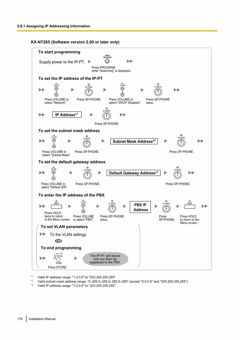
KX-NT265 (Software version 2.00 or later only)
IP Address*1
Subnet Mask Address*2
Default Gateway Address*3
To set the IP address of the IP-PT
To set the subnet mask address
To set the default gateway address
To enter the IP address of the PBX
To start programming
Supply power to the IP-PT.
Press PROGRAMwhile "Searching" is displayed.
PROG.
Press VOLUME toselect "Network".
VOL
Press SP-PHONE. Press VOLUME to select "DHCP (Disable)".
VOL
Press SP-PHONEtwice.
Press SP-PHONE.
Press VOLUME toselect "Subnet Mask".
VOL
Press SP-PHONE. Press SP-PHONE.
Press VOLUME toselect "Default GW".
VOL
Press SP-PHONE. Press SP-PHONE.
Press HOLDtwice to returnto the Menu screen.
HOLD
Press VOLUME to select "PBX".
VOL
Press SP-PHONEtwice.
Press SP-PHONE.
To the VLAN settings
The IP-PT will reboot and can then be
registered to the PBX.
To end programming
To set VLAN parameters
OR
Press STORE.
PBX IP
Address
Press HOLDto return to theMenu screen.
HOLD
*1 Valid IP address range: "1.0.0.0" to "223.255.255.255"*2 Valid subnet mask address range: "0–255.0–255.0–255.0–255" (except "0.0.0.0" and "255.255.255.255")*3 Valid IP address range: "1.0.0.0" to "223.255.255.255"
176 Installation Manual
5.8.1 Assigning IP Addressing Information
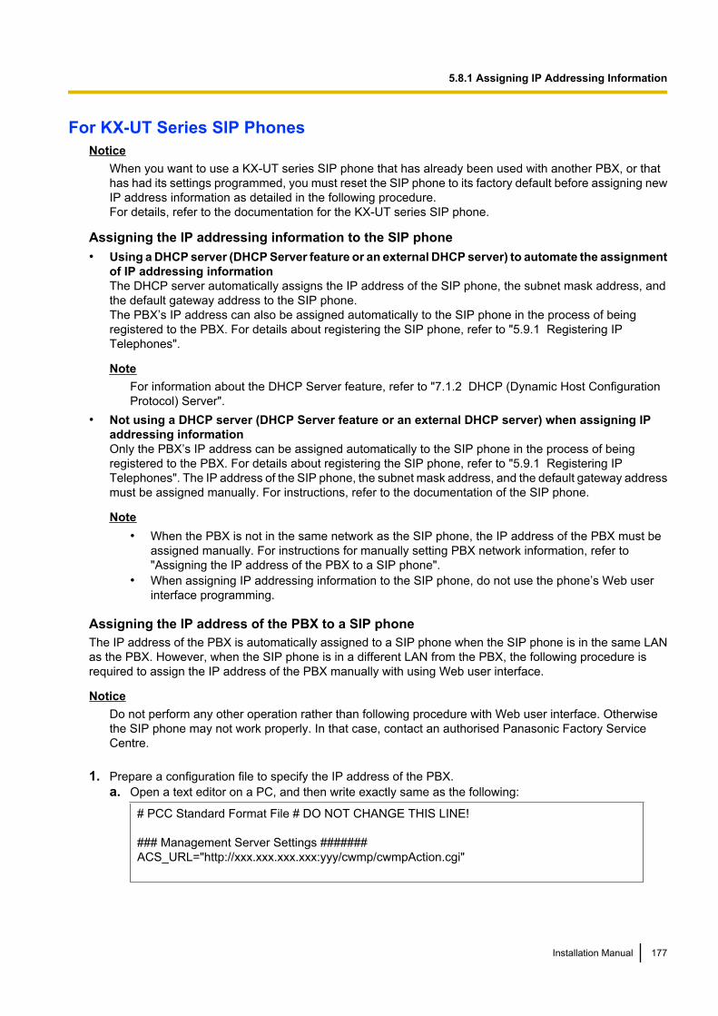
For KX-UT Series SIP PhonesNotice
When you want to use a KX-UT series SIP phone that has already been used with another PBX, or thathas had its settings programmed, you must reset the SIP phone to its factory default before assigning newIP address information as detailed in the following procedure.For details, refer to the documentation for the KX-UT series SIP phone.
Assigning the IP addressing information to the SIP phone• Using a DHCP server (DHCP Server feature or an external DHCP server) to automate the assignment
of IP addressing informationThe DHCP server automatically assigns the IP address of the SIP phone, the subnet mask address, andthe default gateway address to the SIP phone.The PBX’s IP address can also be assigned automatically to the SIP phone in the process of beingregistered to the PBX. For details about registering the SIP phone, refer to "5.9.1 Registering IPTelephones".
NoteFor information about the DHCP Server feature, refer to "7.1.2 DHCP (Dynamic Host ConfigurationProtocol) Server".
• Not using a DHCP server (DHCP Server feature or an external DHCP server) when assigning IPaddressing informationOnly the PBX’s IP address can be assigned automatically to the SIP phone in the process of beingregistered to the PBX. For details about registering the SIP phone, refer to "5.9.1 Registering IPTelephones". The IP address of the SIP phone, the subnet mask address, and the default gateway addressmust be assigned manually. For instructions, refer to the documentation of the SIP phone.
Note• When the PBX is not in the same network as the SIP phone, the IP address of the PBX must be
assigned manually. For instructions for manually setting PBX network information, refer to"Assigning the IP address of the PBX to a SIP phone".
• When assigning IP addressing information to the SIP phone, do not use the phone’s Web userinterface programming.
Assigning the IP address of the PBX to a SIP phoneThe IP address of the PBX is automatically assigned to a SIP phone when the SIP phone is in the same LANas the PBX. However, when the SIP phone is in a different LAN from the PBX, the following procedure isrequired to assign the IP address of the PBX manually with using Web user interface.
NoticeDo not perform any other operation rather than following procedure with Web user interface. Otherwisethe SIP phone may not work properly. In that case, contact an authorised Panasonic Factory ServiceCentre.
1. Prepare a configuration file to specify the IP address of the PBX.a. Open a text editor on a PC, and then write exactly same as the following:
# PCC Standard Format File # DO NOT CHANGE THIS LINE!
### Management Server Settings #######ACS_URL="http://xxx.xxx.xxx.xxx:yyy/cwmp/cwmpAction.cgi"
Installation Manual 177
5.8.1 Assigning IP Addressing Information
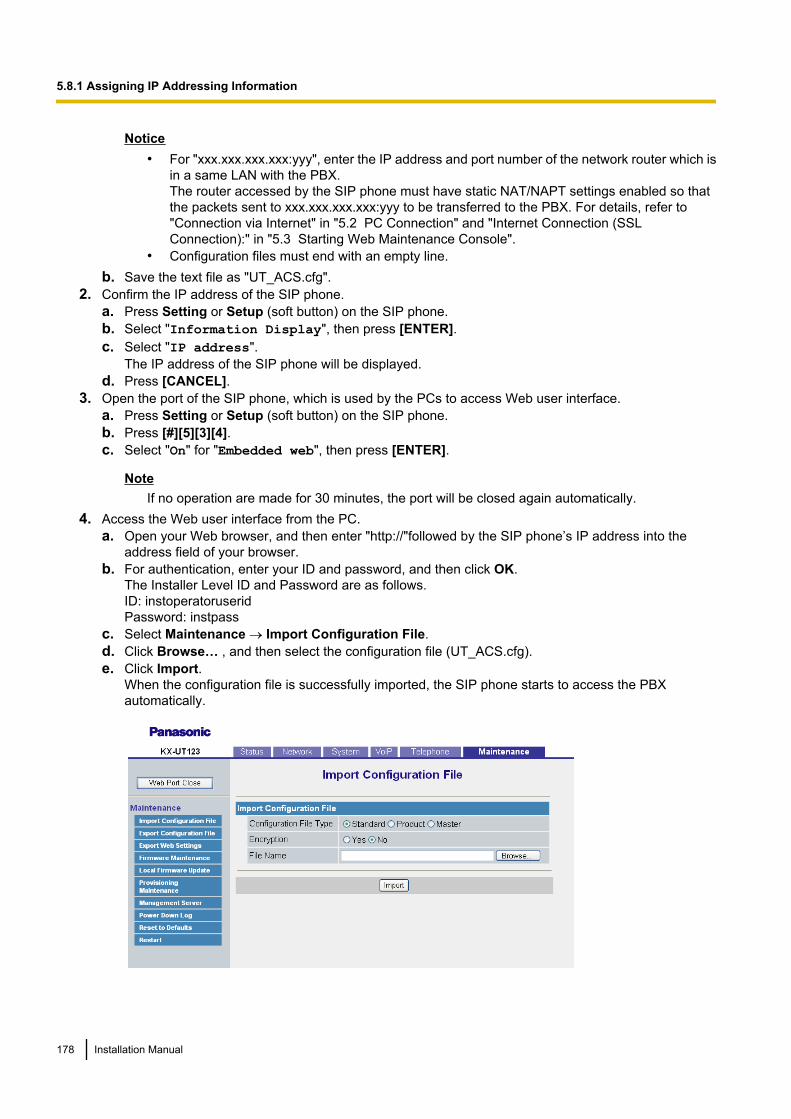
Notice• For "xxx.xxx.xxx.xxx:yyy", enter the IP address and port number of the network router which is
in a same LAN with the PBX.The router accessed by the SIP phone must have static NAT/NAPT settings enabled so thatthe packets sent to xxx.xxx.xxx.xxx:yyy to be transferred to the PBX. For details, refer to"Connection via Internet" in "5.2 PC Connection" and "Internet Connection (SSLConnection):" in "5.3 Starting Web Maintenance Console".
• Configuration files must end with an empty line.b. Save the text file as "UT_ACS.cfg".
2. Confirm the IP address of the SIP phone.a. Press Setting or Setup (soft button) on the SIP phone.b. Select "Information Display", then press [ENTER].c. Select "IP address".
The IP address of the SIP phone will be displayed.d. Press [CANCEL].
3. Open the port of the SIP phone, which is used by the PCs to access Web user interface.a. Press Setting or Setup (soft button) on the SIP phone.b. Press [#][5][3][4].c. Select "On" for "Embedded web", then press [ENTER].
NoteIf no operation are made for 30 minutes, the port will be closed again automatically.
4. Access the Web user interface from the PC.a. Open your Web browser, and then enter "http://"followed by the SIP phone’s IP address into the
address field of your browser.b. For authentication, enter your ID and password, and then click OK.
The Installer Level ID and Password are as follows.ID: instoperatoruseridPassword: instpass
c. Select Maintenance ® Import Configuration File.d. Click Browse… , and then select the configuration file (UT_ACS.cfg).e. Click Import.
When the configuration file is successfully imported, the SIP phone starts to access the PBXautomatically.
178 Installation Manual
5.8.1 Assigning IP Addressing Information
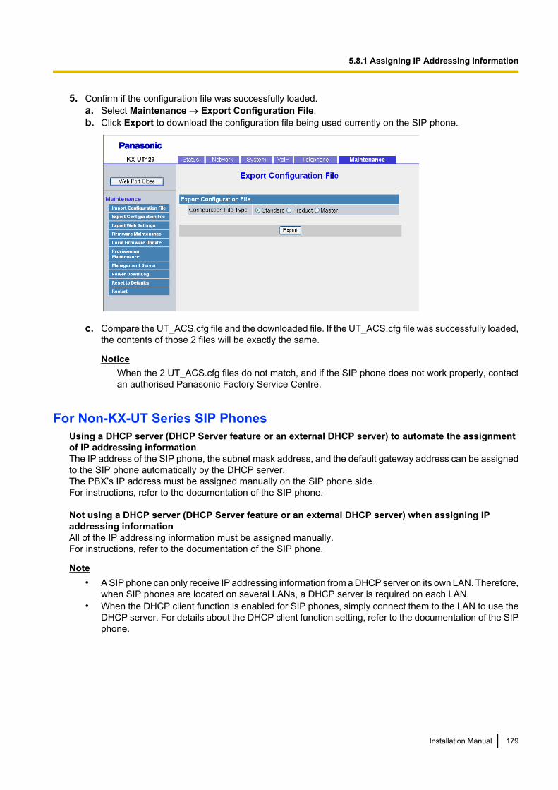
5. Confirm if the configuration file was successfully loaded.a. Select Maintenance ® Export Configuration File.b. Click Export to download the configuration file being used currently on the SIP phone.
c. Compare the UT_ACS.cfg file and the downloaded file. If the UT_ACS.cfg file was successfully loaded,the contents of those 2 files will be exactly the same.
NoticeWhen the 2 UT_ACS.cfg files do not match, and if the SIP phone does not work properly, contactan authorised Panasonic Factory Service Centre.
For Non-KX-UT Series SIP PhonesUsing a DHCP server (DHCP Server feature or an external DHCP server) to automate the assignmentof IP addressing informationThe IP address of the SIP phone, the subnet mask address, and the default gateway address can be assignedto the SIP phone automatically by the DHCP server.The PBX’s IP address must be assigned manually on the SIP phone side.For instructions, refer to the documentation of the SIP phone.
Not using a DHCP server (DHCP Server feature or an external DHCP server) when assigning IPaddressing informationAll of the IP addressing information must be assigned manually.For instructions, refer to the documentation of the SIP phone.
Note• A SIP phone can only receive IP addressing information from a DHCP server on its own LAN. Therefore,
when SIP phones are located on several LANs, a DHCP server is required on each LAN.• When the DHCP client function is enabled for SIP phones, simply connect them to the LAN to use the
DHCP server. For details about the DHCP client function setting, refer to the documentation of the SIPphone.
Installation Manual 179
5.8.1 Assigning IP Addressing Information
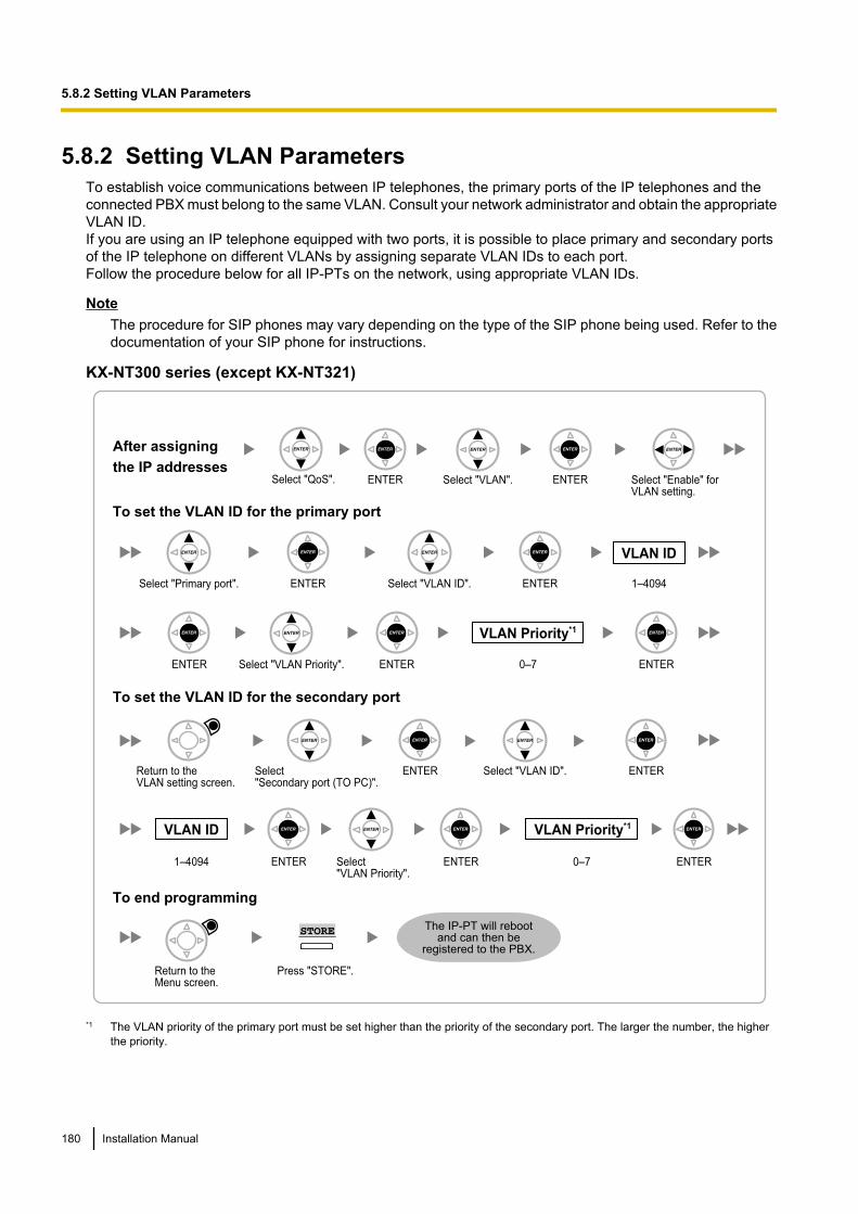
5.8.2 Setting VLAN ParametersTo establish voice communications between IP telephones, the primary ports of the IP telephones and theconnected PBX must belong to the same VLAN. Consult your network administrator and obtain the appropriateVLAN ID.If you are using an IP telephone equipped with two ports, it is possible to place primary and secondary portsof the IP telephone on different VLANs by assigning separate VLAN IDs to each port.Follow the procedure below for all IP-PTs on the network, using appropriate VLAN IDs.
NoteThe procedure for SIP phones may vary depending on the type of the SIP phone being used. Refer to thedocumentation of your SIP phone for instructions.
KX-NT300 series (except KX-NT321)
Select "VLAN". ENTER
ENTER
VLAN ID
ENTER
VLAN Priority*1
1
ENTER
Press "STORE".
STORE
To set the VLAN ID for the primary port
To set the VLAN ID for the secondary port
To end programming
0–7
1–4094Select "Primary port".
ENTER
VLAN ID
ENTER
VLAN Priority*1
ENTER1–4094
Select"Secondary port (TO PC)".
Select "VLAN Priority". ENTER
Return to the VLAN setting screen.
ENTER
ENTER
Select "VLAN Priority".
ENTER
Return to the Menu screen.
Select "Enable" for VLAN setting.
Select "VLAN ID".
Select "VLAN ID".
0–7
After assigning
the IP addressesSelect "QoS". ENTER
The IP-PT will reboot and can then be
registered to the PBX.
*1 The VLAN priority of the primary port must be set higher than the priority of the secondary port. The larger the number, the higherthe priority.
180 Installation Manual
5.8.2 Setting VLAN Parameters
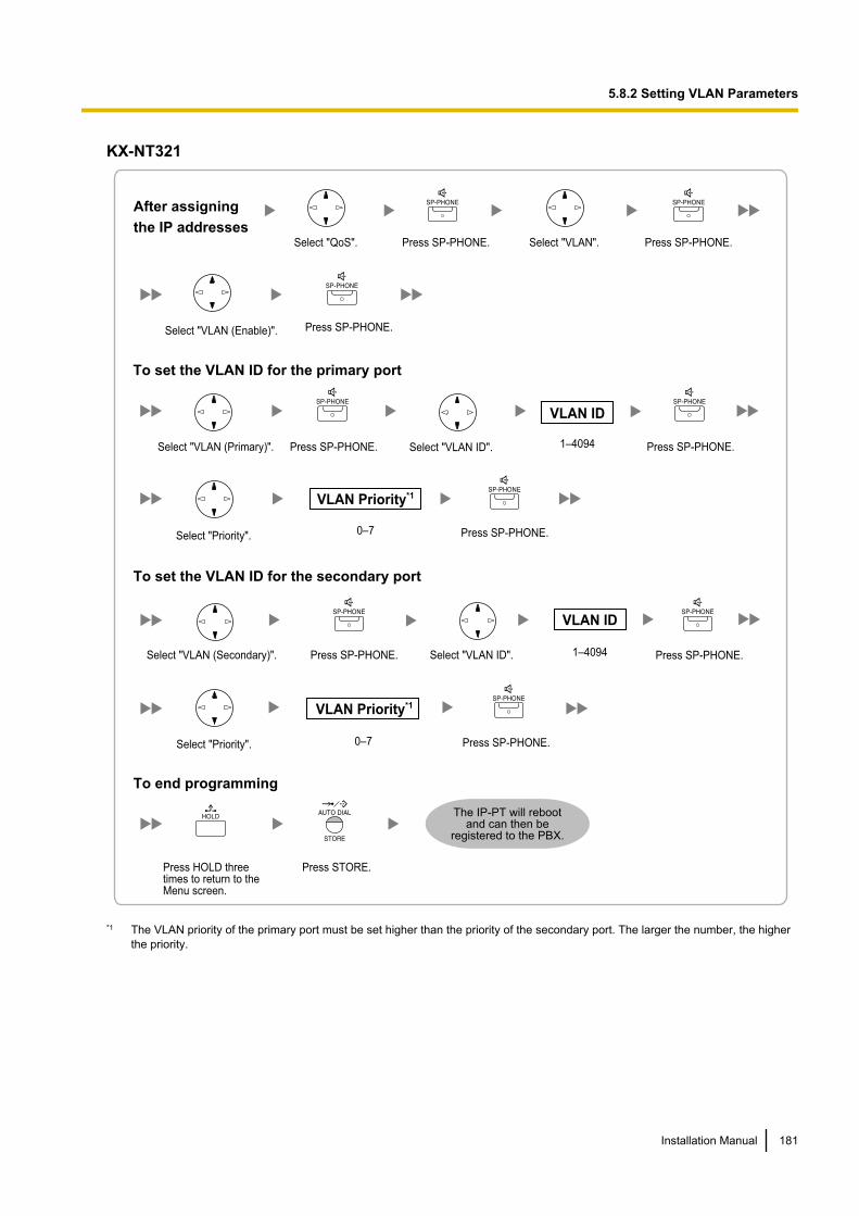
KX-NT321
To end programming
After assigning
the IP addresses
Select "QoS". Press SP-PHONE. Select "VLAN". Press SP-PHONE.
Press STORE.Press HOLD three times to return to the Menu screen.
Select "VLAN (Enable)". Press SP-PHONE.
VLAN ID
VLAN Priority*1
To set the VLAN ID for the primary port
0–7
1–4094
Select "Priority".
Select "VLAN (Primary)". Press SP-PHONE. Press SP-PHONE.Select "VLAN ID".
Press SP-PHONE.
To set the VLAN ID for the secondary port
VLAN ID
VLAN Priority*1
1–4094
0–7
Select "VLAN (Secondary)". Press SP-PHONE. Select "VLAN ID".
Select "Priority".
Press SP-PHONE.
Press SP-PHONE.
The IP-PT will reboot and can then be
registered to the PBX.
*1 The VLAN priority of the primary port must be set higher than the priority of the secondary port. The larger the number, the higherthe priority.
Installation Manual 181
5.8.2 Setting VLAN Parameters
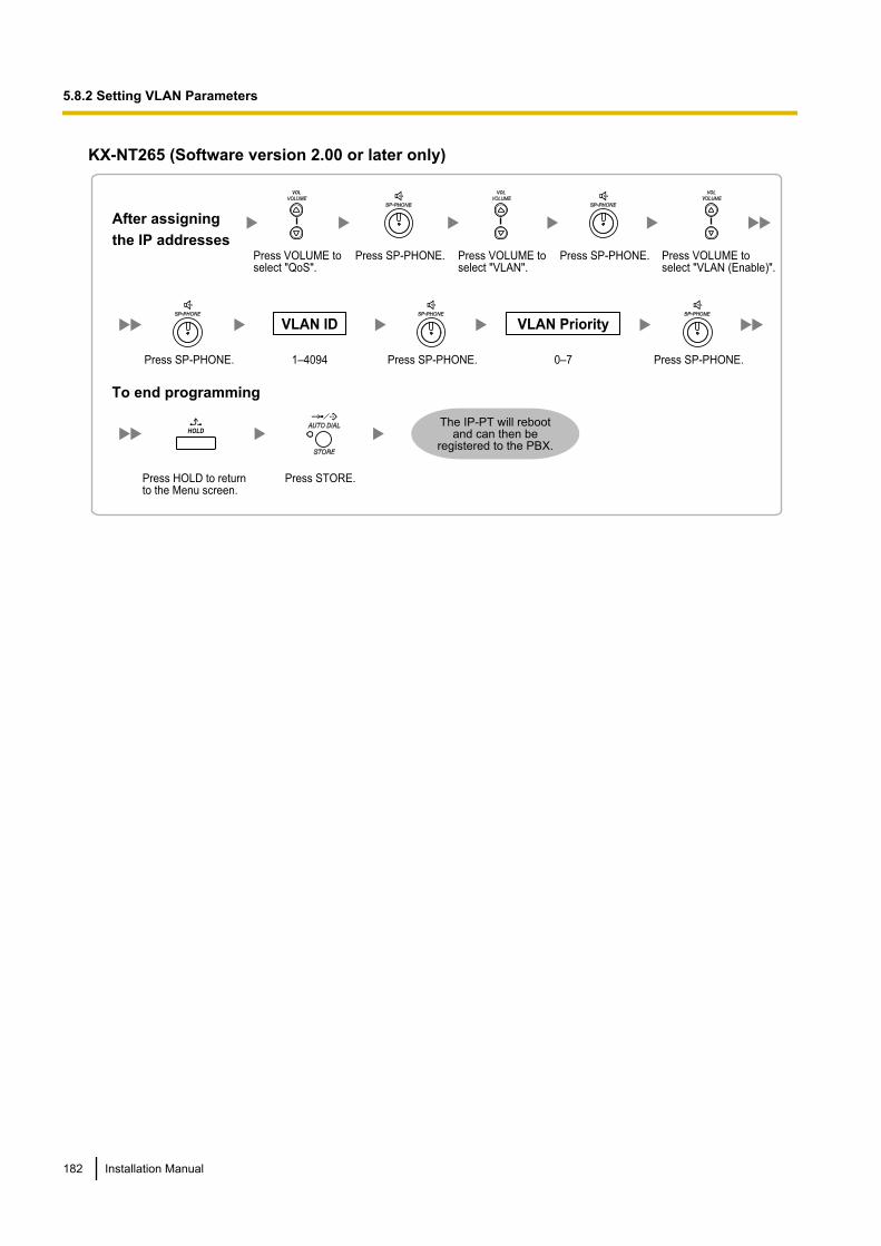
KX-NT265 (Software version 2.00 or later only)
VLAN ID VLAN Priority
To end programming
0–71–4094
After assigning
the IP addresses
Press VOLUME toselect "VLAN".
VOL
Press VOLUME toselect "QoS".
VOL
Press SP-PHONE.Press SP-PHONE. Press VOLUME toselect "VLAN (Enable)".
VOL
Press SP-PHONE.Press SP-PHONE. Press SP-PHONE.
Press STORE.Press HOLD to return to the Menu screen.
HOLD
The IP-PT will reboot and can then be
registered to the PBX.
182 Installation Manual
5.8.2 Setting VLAN Parameters
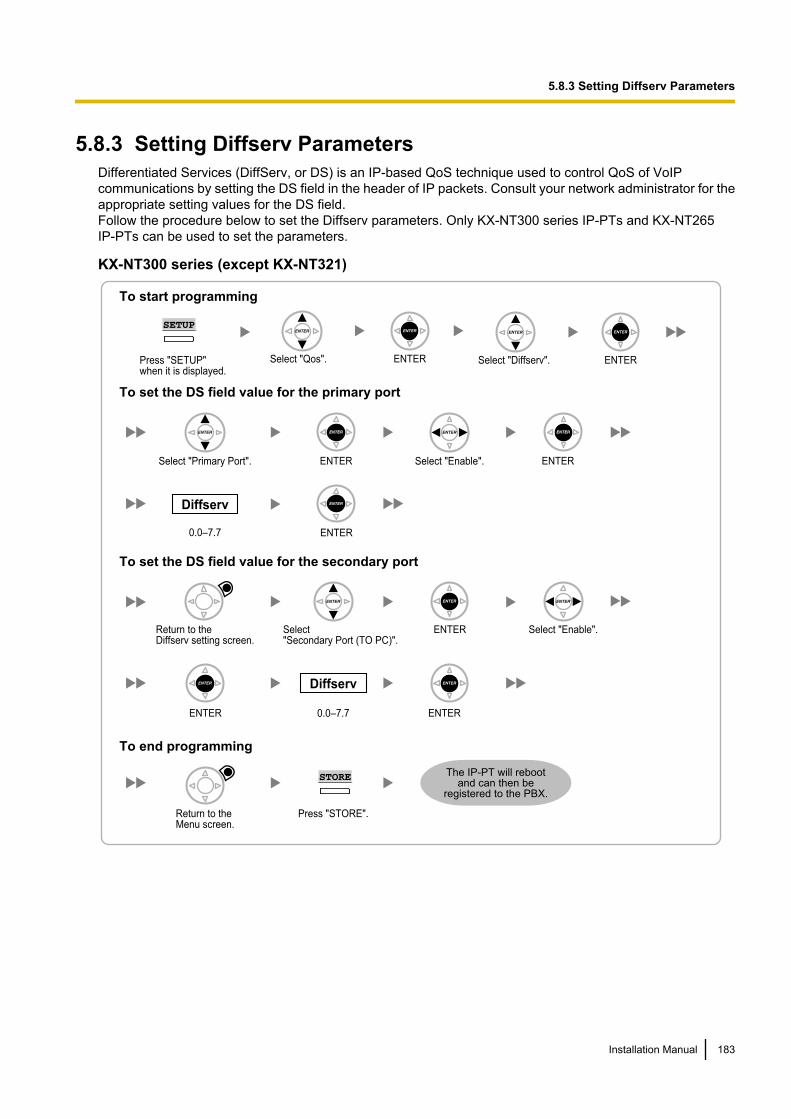
5.8.3 Setting Diffserv ParametersDifferentiated Services (DiffServ, or DS) is an IP-based QoS technique used to control QoS of VoIPcommunications by setting the DS field in the header of IP packets. Consult your network administrator for theappropriate setting values for the DS field.Follow the procedure below to set the Diffserv parameters. Only KX-NT300 series IP-PTs and KX-NT265IP-PTs can be used to set the parameters.
KX-NT300 series (except KX-NT321)
Select "Diffserv". ENTER
To set the DS field value for the primary port
To set the DS field value for the secondary port
To end programming
Select "Primary Port".
ENTERENTER
Diffserv
0.0–7.7
Return to the Diffserv setting screen.
ENTER
Return to the Menu screen.
ENTER ENTERSelect "Enable".
ENTERSelect"Secondary Port (TO PC)".
Select "Enable".
Press "STORE".
STORE
Diffserv
0.0–7.7
To start programming
Select "Qos". ENTERPress "SETUP" when it is displayed.
SETUP
The IP-PT will reboot and can then be
registered to the PBX.
Installation Manual 183
5.8.3 Setting Diffserv Parameters
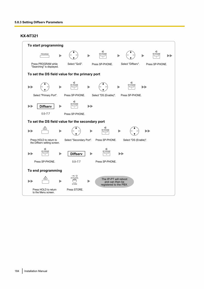
KX-NT321
To set the DS field value for the primary port
To set the DS field value for the secondary port
To start programming
Press PROGRAM while "Searching" is displayed.
Select "QoS". Select "Diffserv".
To end programming
Press STORE.Press HOLD to return to the Menu screen.
Select "Primary Port".
Diffserv
0.0–7.7
Press SP-PHONE. Press SP-PHONE.
Select "DS (Enable)".Press SP-PHONE. Press SP-PHONE.
Press SP-PHONE.
Press HOLD to return to the Diffserv setting screen.
Select "Secondary Port". Select "DS (Enable)".Press SP-PHONE.
Press SP-PHONE.Press SP-PHONE.
Diffserv
0.0–7.7
The IP-PT will reboot and can then be
registered to the PBX.
184 Installation Manual
5.8.3 Setting Diffserv Parameters
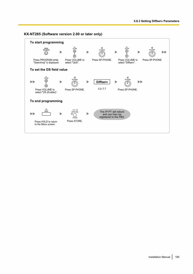
KX-NT265 (Software version 2.00 or later only)
To set the DS field value
To start programming
Press PROGRAM while "Searching" is displayed.
PROG.
Press VOLUME toselect "QoS".
VOL
Press SP-PHONE. Press VOLUME to select "Diffserv".
VOL
Press SP-PHONE.
To end programming
Press STORE.Press HOLD to return to the Menu screen.
HOLD
Press VOLUME to select "DS (Enable)".
VOL
Press SP-PHONE.
Diffserv
0.0–7.7 Press SP-PHONE.
The IP-PT will reboot and can then be
registered to the PBX.
Installation Manual 185
5.8.3 Setting Diffserv Parameters
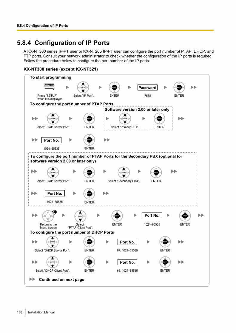
5.8.4 Configuration of IP PortsA KX-NT300 series IP-PT user or KX-NT265 IP-PT user can configure the port number of PTAP, DHCP, andFTP ports. Consult your network administrator to check whether the configuration of the IP ports is required.Follow the procedure below to configure the port number of the IP ports.
KX-NT300 series (except KX-NT321)
Select "IP Port". ENTER 7678 ENTER
ENTER
ENTER
ENTER
ENTER
ENTER
ENTER
1024–65535
Port No.
Password
To configure the port number of PTAP Ports
To start programming
Select "PTAP Server Port".
Select "PTAP Server Port".
Select "Primary PBX".
Select "Secondary PBX".
To configure the port number of DHCP Ports
ENTER 1024–65535 ENTER
Port No.
Select "PTAP Client Port".
ENTER 67, 1024–65535 ENTER
Port No.
Select "DHCP Server Port".
ENTER 68, 1024–65535 ENTER
Port No.
Select "DHCP Client Port".
Press "SETUP" when it is displayed.
SETUP
Continued on next page
1024–65535
Port No.
To configure the port number of PTAP Ports for the Secondary PBX (optional for
software version 2.00 or later only)
Software version 2.00 or later only
Return to the Menu screen.
186 Installation Manual
5.8.4 Configuration of IP Ports
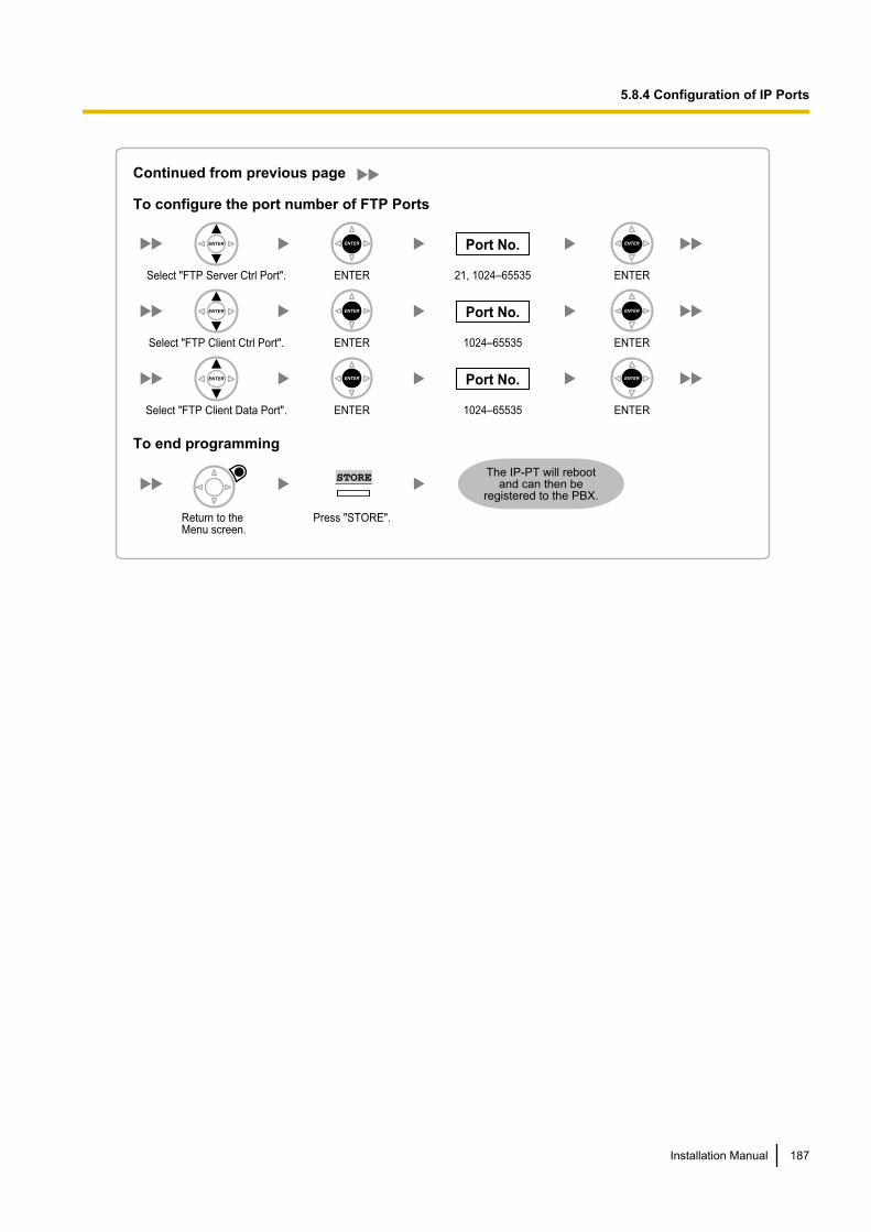
Press "STORE".
STORE
To configure the port number of FTP Ports
To end programming
ENTER 21, 1024–65535 ENTER
Port No.
Select "FTP Server Ctrl Port".
ENTER 1024–65535 ENTER
Port No.
Select "FTP Client Ctrl Port".
1024–65535ENTER ENTER
Port No.
Select "FTP Client Data Port".
Return to the Menu screen.
Continued from previous page
The IP-PT will reboot and can then be
registered to the PBX.
Installation Manual 187
5.8.4 Configuration of IP Ports
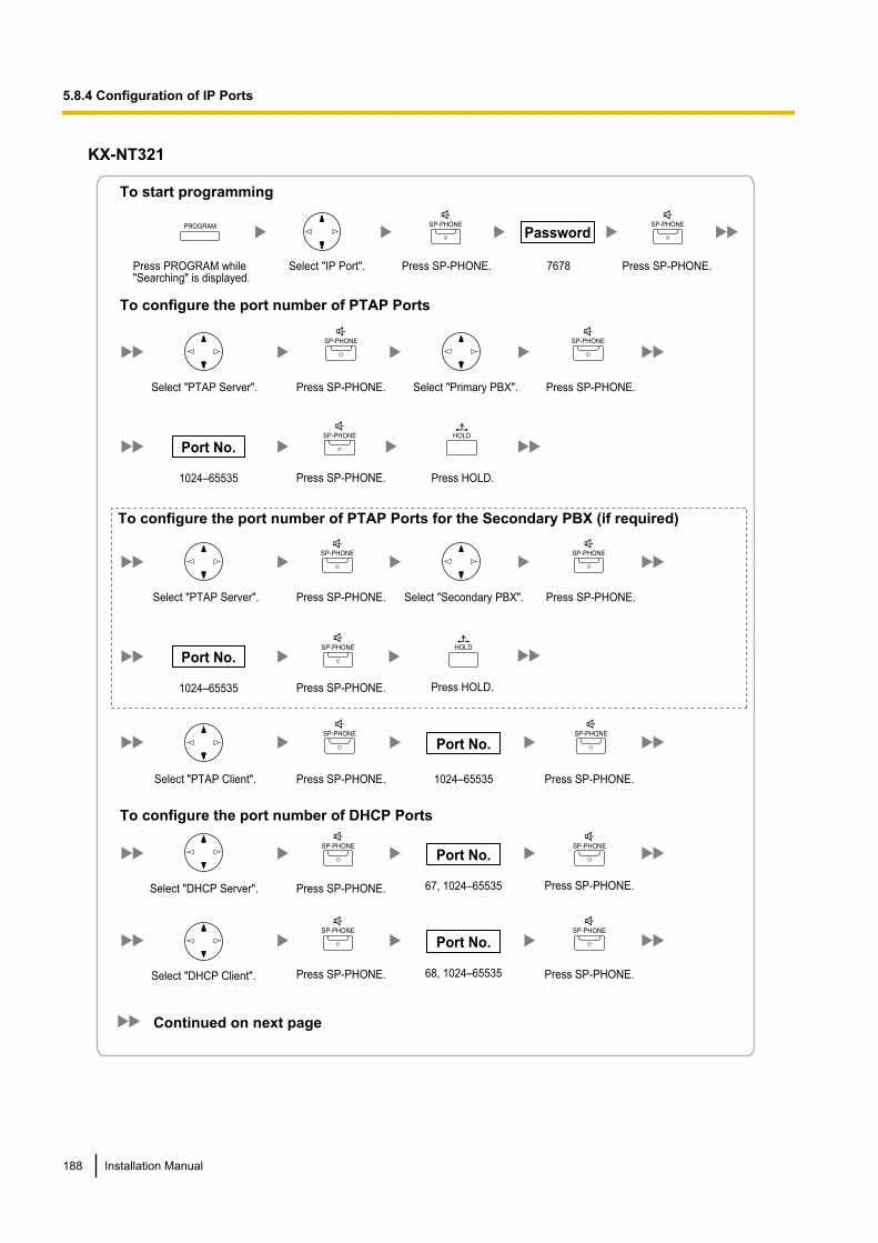
KX-NT321
To configure the port number of PTAP Ports
To configure the port number of DHCP Ports
To start programming
Press PROGRAM while "Searching" is displayed.
Select "IP Port".
Select "PTAP Server".
7678
Password
1024–65535
Port No.
Select "PTAP Client".
Select "DHCP Server".
Select "DHCP Client".
Press SP-PHONE. Press SP-PHONE.
Select "Primary PBX".Press SP-PHONE. Press SP-PHONE.
1024–65535
Port No.
Press SP-PHONE. Press SP-PHONE.
67, 1024–65535
Port No.
Press SP-PHONE. Press SP-PHONE.
68, 1024–65535
Port No.
Press SP-PHONE. Press SP-PHONE.
Press SP-PHONE.
Select "PTAP Server".
1024–65535
Port No.
Select "Secondary PBX".Press SP-PHONE. Press SP-PHONE.
Press SP-PHONE.
Continued on next page
To configure the port number of PTAP Ports for the Secondary PBX (if required)
Press HOLD.
Press HOLD.
188 Installation Manual
5.8.4 Configuration of IP Ports
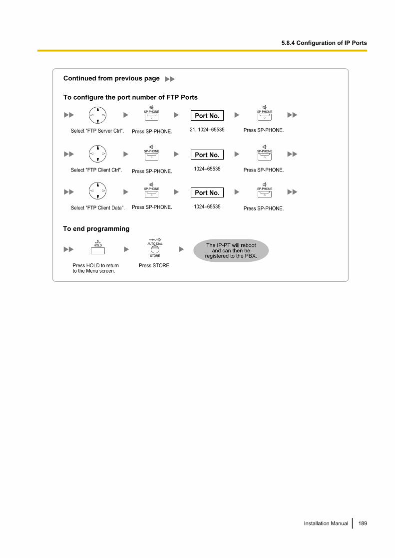
Continued from previous page
To end programming
Press STORE.Press HOLD to return to the Menu screen.
To configure the port number of FTP Ports
Select "FTP Server Ctrl". 21, 1024–65535
Port No.
Select "FTP Client Ctrl". 1024–65535
Port No.
Select "FTP Client Data". 1024–65535
Port No.
Press SP-PHONE.
Press SP-PHONE.
Press SP-PHONE.
Press SP-PHONE.
Press SP-PHONE.
Press SP-PHONE.
The IP-PT will reboot and can then be
registered to the PBX.
Installation Manual 189
5.8.4 Configuration of IP Ports
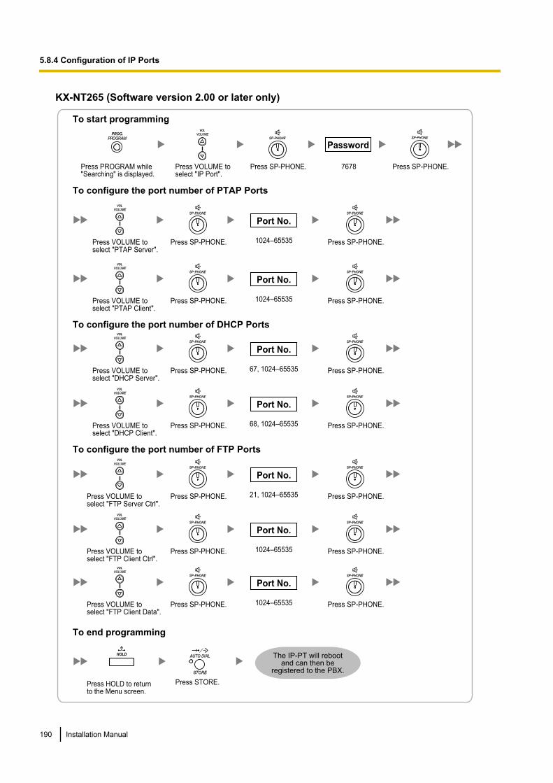
KX-NT265 (Software version 2.00 or later only)
To configure the port number of PTAP Ports
To configure the port number of DHCP Ports
To configure the port number of FTP Ports
To start programming
Press PROGRAM while "Searching" is displayed.
PROG.
Press VOLUME toselect "IP Port".
VOL
Press SP-PHONE. Press SP-PHONE.
To end programming
Press STORE.Press HOLD to return to the Menu screen.
HOLD
Press VOLUME to select "PTAP Server".
VOL
Press SP-PHONE. Press SP-PHONE.
7678
Password
1024–65535
Port No.
Press VOLUME to select "PTAP Client".
VOL
Press SP-PHONE. Press SP-PHONE.1024–65535
Port No.
Press VOLUME to select "DHCP Server".
VOL
Press SP-PHONE. Press SP-PHONE.67, 1024–65535
Port No.
Press VOLUME to select "DHCP Client".
VOL
Press SP-PHONE. Press SP-PHONE.68, 1024–65535
Port No.
Press VOLUME to select "FTP Server Ctrl".
VOL
Press SP-PHONE. Press SP-PHONE.21, 1024–65535
Port No.
Press VOLUME to select "FTP Client Ctrl".
VOL
Press SP-PHONE. Press SP-PHONE.1024–65535
Port No.
Press VOLUME to select "FTP Client Data".
VOL
Press SP-PHONE. Press SP-PHONE.1024–65535
Port No.
The IP-PT will reboot and can then be
registered to the PBX.
190 Installation Manual
5.8.4 Configuration of IP Ports

NoteIf you wish to change the port number back to default, enter 0 as the port number for the desired port.
Installation Manual 191
5.8.4 Configuration of IP Ports
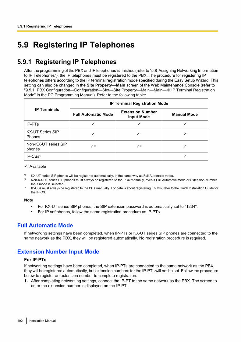
5.9 Registering IP Telephones
5.9.1 Registering IP TelephonesAfter the programming of the PBX and IP telephones is finished (refer to "5.8 Assigning Networking Informationto IP Telephones"), the IP telephones must be registered to the PBX. The procedure for registering IPtelephones differs according to the IP terminal registration mode specified during the Easy Setup Wizard. Thissetting can also be changed in the Site Property—Main screen of the Web Maintenance Console (refer to"9.5.1 PBX Configuration—Configuration—Slot—Site Property—Main—Main— IP Terminal RegistrationMode" in the PC Programming Manual). Refer to the following table:
IP TerminalsIP Terminal Registration Mode
Full Automatic Mode Extension NumberInput Mode Manual Mode
IP-PTs ü ü ü
KX-UT Series SIPPhones ü ü*1 ü
Non-KX-UT series SIPphones ü*2 ü*2 ü
IP-CSs*3 ü
ü: Available
*1 KX-UT series SIP phones will be registered automatically, in the same way as Full Automatic mode.*2 Non-KX-UT series SIP phones must always be registered to the PBX manually, even if Full Automatic mode or Extension Number
Input mode is selected.*3 IP-CSs must always be registered to the PBX manually. For details about registering IP-CSs, refer to the Quick Installation Guide for
the IP-CS.
Note• For KX-UT series SIP phones, the SIP extension password is automatically set to "1234".• For IP softphones, follow the same registration procedure as IP-PTs.
Full Automatic ModeIf networking settings have been completed, when IP-PTs or KX-UT series SIP phones are connected to thesame network as the PBX, they will be registered automatically. No registration procedure is required.
Extension Number Input ModeFor IP-PTsIf networking settings have been completed, when IP-PTs are connected to the same network as the PBX,they will be registered automatically, but extension numbers for the IP-PTs will not be set. Follow the procedurebelow to register an extension number to complete registration.1. After completing networking settings, connect the IP-PT to the same network as the PBX. The screen to
enter the extension number is displayed on the IP-PT.
192 Installation Manual
5.9.1 Registering IP Telephones
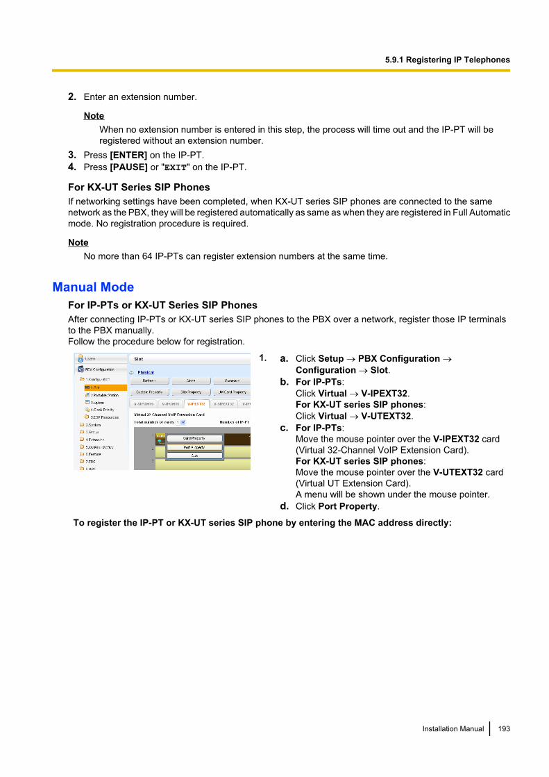
2. Enter an extension number.
NoteWhen no extension number is entered in this step, the process will time out and the IP-PT will beregistered without an extension number.
3. Press [ENTER] on the IP-PT.4. Press [PAUSE] or "EXIT" on the IP-PT.
For KX-UT Series SIP PhonesIf networking settings have been completed, when KX-UT series SIP phones are connected to the samenetwork as the PBX, they will be registered automatically as same as when they are registered in Full Automaticmode. No registration procedure is required.
NoteNo more than 64 IP-PTs can register extension numbers at the same time.
Manual ModeFor IP-PTs or KX-UT Series SIP PhonesAfter connecting IP-PTs or KX-UT series SIP phones to the PBX over a network, register those IP terminalsto the PBX manually.Follow the procedure below for registration.
1. a. Click Setup ® PBX Configuration ®Configuration ® Slot.
b. For IP-PTs:Click Virtual ® V-IPEXT32.For KX-UT series SIP phones:Click Virtual ® V-UTEXT32.
c. For IP-PTs:Move the mouse pointer over the V-IPEXT32 card(Virtual 32-Channel VoIP Extension Card).For KX-UT series SIP phones:Move the mouse pointer over the V-UTEXT32 card(Virtual UT Extension Card).A menu will be shown under the mouse pointer.
d. Click Port Property.
To register the IP-PT or KX-UT series SIP phone by entering the MAC address directly:
Installation Manual 193
5.9.1 Registering IP Telephones
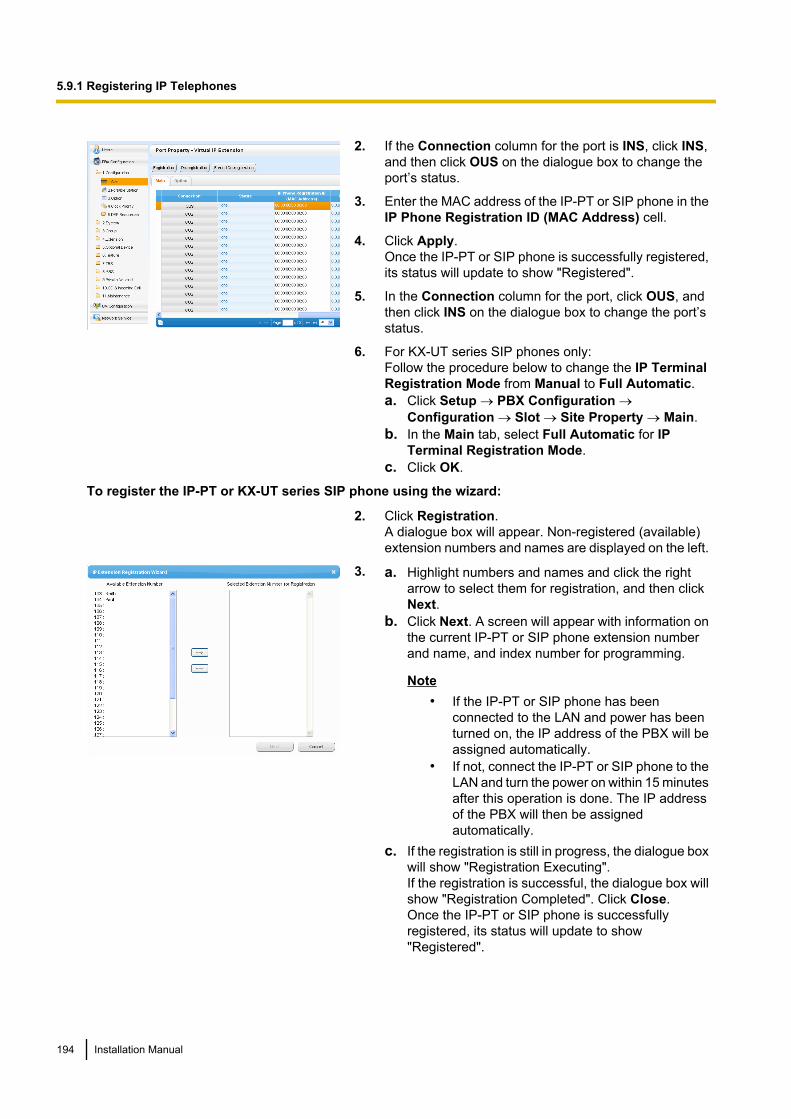
2. If the Connection column for the port is INS, click INS,and then click OUS on the dialogue box to change theport’s status.
3. Enter the MAC address of the IP-PT or SIP phone in theIP Phone Registration ID (MAC Address) cell.
4. Click Apply.Once the IP-PT or SIP phone is successfully registered,its status will update to show "Registered".
5. In the Connection column for the port, click OUS, andthen click INS on the dialogue box to change the port’sstatus.
6. For KX-UT series SIP phones only:Follow the procedure below to change the IP TerminalRegistration Mode from Manual to Full Automatic.a. Click Setup ® PBX Configuration ®
Configuration ® Slot ® Site Property ® Main.b. In the Main tab, select Full Automatic for IP
Terminal Registration Mode.c. Click OK.
To register the IP-PT or KX-UT series SIP phone using the wizard:
2. Click Registration.A dialogue box will appear. Non-registered (available)extension numbers and names are displayed on the left.
3. a. Highlight numbers and names and click the rightarrow to select them for registration, and then clickNext.
b. Click Next. A screen will appear with information onthe current IP-PT or SIP phone extension numberand name, and index number for programming.
Note• If the IP-PT or SIP phone has been
connected to the LAN and power has beenturned on, the IP address of the PBX will beassigned automatically.
• If not, connect the IP-PT or SIP phone to theLAN and turn the power on within 15 minutesafter this operation is done. The IP addressof the PBX will then be assignedautomatically.
c. If the registration is still in progress, the dialogue boxwill show "Registration Executing".If the registration is successful, the dialogue box willshow "Registration Completed". Click Close.Once the IP-PT or SIP phone is successfullyregistered, its status will update to show"Registered".
194 Installation Manual
5.9.1 Registering IP Telephones
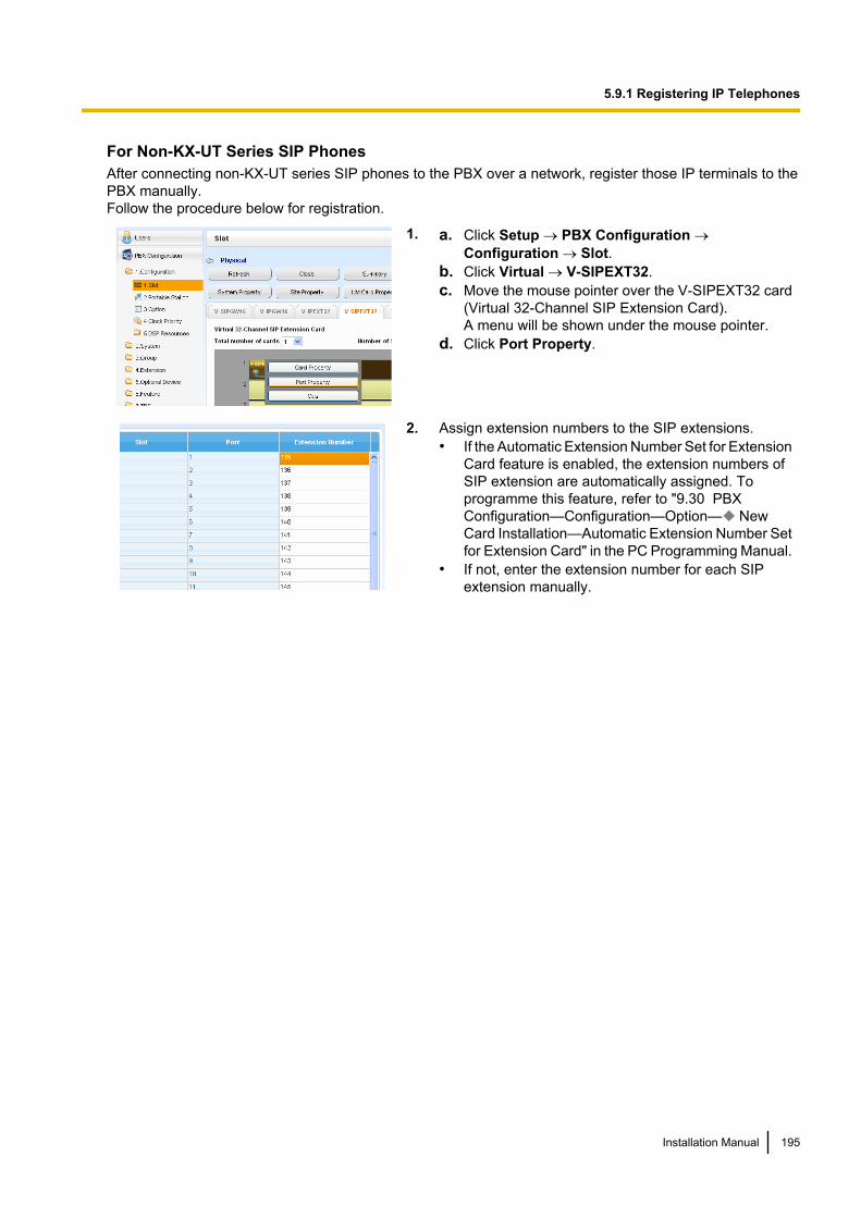
For Non-KX-UT Series SIP PhonesAfter connecting non-KX-UT series SIP phones to the PBX over a network, register those IP terminals to thePBX manually.Follow the procedure below for registration.
1. a. Click Setup ® PBX Configuration ®Configuration ® Slot.
b. Click Virtual ® V-SIPEXT32.c. Move the mouse pointer over the V-SIPEXT32 card
(Virtual 32-Channel SIP Extension Card).A menu will be shown under the mouse pointer.
d. Click Port Property.
2. Assign extension numbers to the SIP extensions.• If the Automatic Extension Number Set for Extension
Card feature is enabled, the extension numbers ofSIP extension are automatically assigned. Toprogramme this feature, refer to "9.30 PBXConfiguration—Configuration—Option— NewCard Installation—Automatic Extension Number Setfor Extension Card" in the PC Programming Manual.
• If not, enter the extension number for each SIPextension manually.
Installation Manual 195
5.9.1 Registering IP Telephones
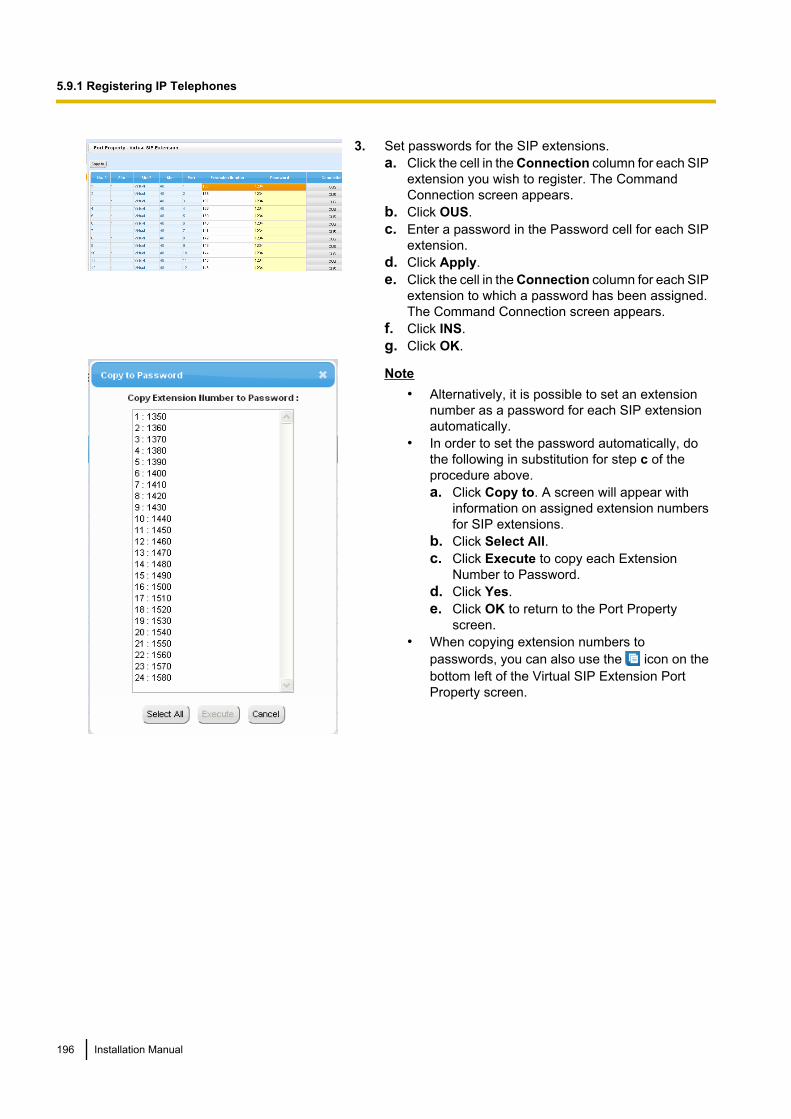
3. Set passwords for the SIP extensions.a. Click the cell in the Connection column for each SIP
extension you wish to register. The CommandConnection screen appears.
b. Click OUS.c. Enter a password in the Password cell for each SIP
extension.d. Click Apply.e. Click the cell in the Connection column for each SIP
extension to which a password has been assigned.The Command Connection screen appears.
f. Click INS.g. Click OK.
Note• Alternatively, it is possible to set an extension
number as a password for each SIP extensionautomatically.
• In order to set the password automatically, dothe following in substitution for step c of theprocedure above.a. Click Copy to. A screen will appear with
information on assigned extension numbersfor SIP extensions.
b. Click Select All.c. Click Execute to copy each Extension
Number to Password.d. Click Yes.e. Click OK to return to the Port Property
screen.• When copying extension numbers to
passwords, you can also use the icon on thebottom left of the Virtual SIP Extension PortProperty screen.
196 Installation Manual
5.9.1 Registering IP Telephones
4. Programme the SIP extension you wish to register.a. Set the IP address of the PBX, extension number,
and password in the corresponding fields for yourSIP extension.
b. Send a request from the SIP extension to the PBXfor registration.• If the authentication information of the SIP
extension and the PBX match, the registration issuccessful.
Note• When programming the SIP extension, the
names of the corresponding fields may differdepending on the type of SIP phone you areusing.
• For details about the actual operation of SIPphones, refer to the documentation of the SIPphone.
• For certain SIP phones, you may need to set aSign-in name, which should consist of theextension number and the IP address of the PBX(e.g., [email protected]).
Installation Manual 197
5.9.1 Registering IP Telephones
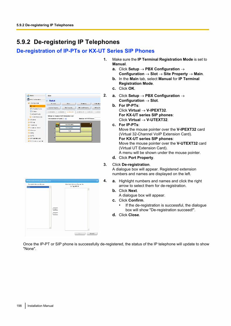
5.9.2 De-registering IP TelephonesDe-registration of IP-PTs or KX-UT Series SIP Phones
1. Make sure the IP Terminal Registration Mode is set toManual.a. Click Setup ® PBX Configuration ®
Configuration ® Slot ® Site Property ® Main.b. In the Main tab, select Manual for IP Terminal
Registration Mode.c. Click OK.
2. a. Click Setup ® PBX Configuration ®Configuration ® Slot.
b. For IP-PTs:Click Virtual ® V-IPEXT32.For KX-UT series SIP phones:Click Virtual ® V-UTEXT32.
c. For IP-PTs:Move the mouse pointer over the V-IPEXT32 card(Virtual 32-Channel VoIP Extension Card).For KX-UT series SIP phones:Move the mouse pointer over the V-UTEXT32 card(Virtual UT Extension Card).A menu will be shown under the mouse pointer.
d. Click Port Property.
3. Click De-registration.A dialogue box will appear. Registered extensionnumbers and names are displayed on the left.
4. a. Highlight numbers and names and click the rightarrow to select them for de-registration.
b. Click Next.A dialogue box will appear.
c. Click Confirm.• If the de-registration is successful, the dialogue
box will show "De-registration succeed!".d. Click Close.
Once the IP-PT or SIP phone is successfully de-registered, the status of the IP telephone will update to show"None".
198 Installation Manual
5.9.2 De-registering IP Telephones
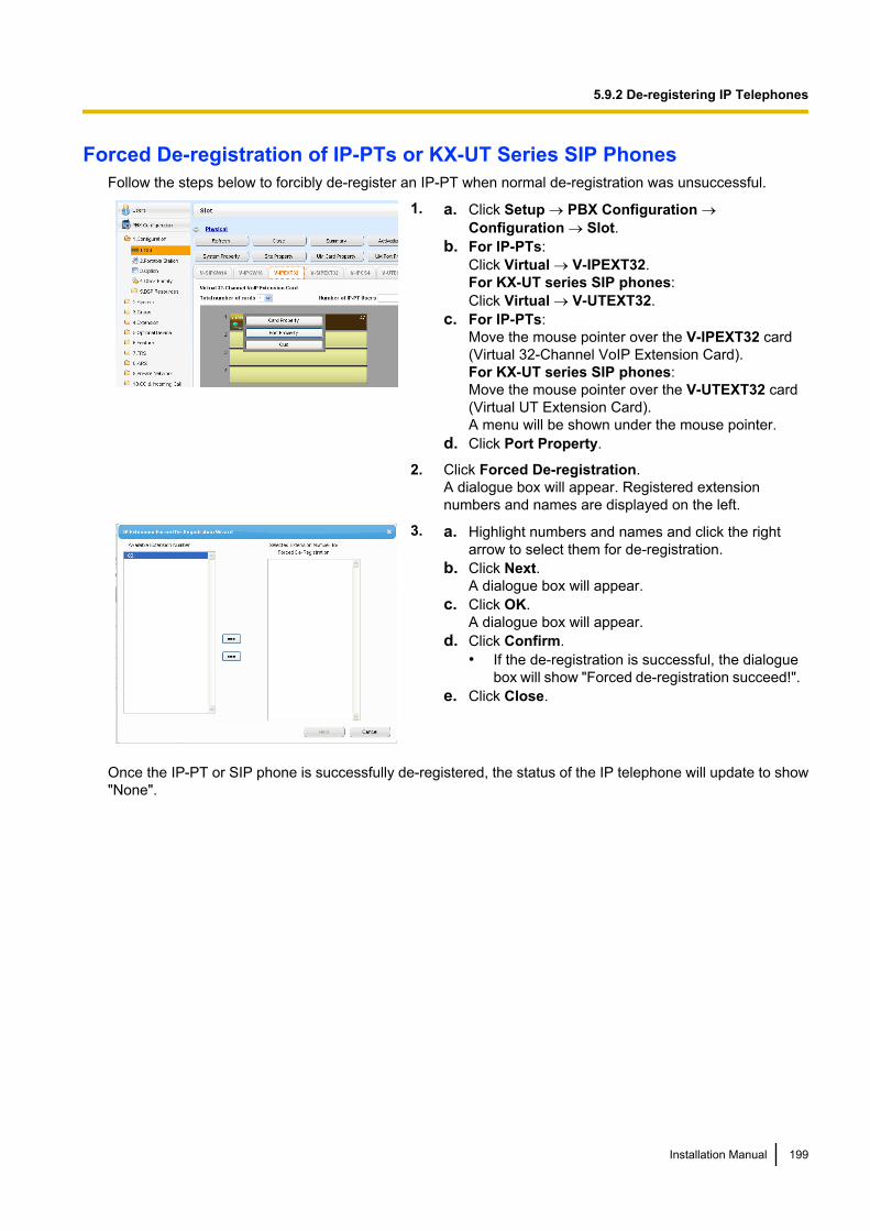
Forced De-registration of IP-PTs or KX-UT Series SIP PhonesFollow the steps below to forcibly de-register an IP-PT when normal de-registration was unsuccessful.
1. a. Click Setup ® PBX Configuration ®Configuration ® Slot.
b. For IP-PTs:Click Virtual ® V-IPEXT32.For KX-UT series SIP phones:Click Virtual ® V-UTEXT32.
c. For IP-PTs:Move the mouse pointer over the V-IPEXT32 card(Virtual 32-Channel VoIP Extension Card).For KX-UT series SIP phones:Move the mouse pointer over the V-UTEXT32 card(Virtual UT Extension Card).A menu will be shown under the mouse pointer.
d. Click Port Property.
2. Click Forced De-registration.A dialogue box will appear. Registered extensionnumbers and names are displayed on the left.
3. a. Highlight numbers and names and click the rightarrow to select them for de-registration.
b. Click Next.A dialogue box will appear.
c. Click OK.A dialogue box will appear.
d. Click Confirm.• If the de-registration is successful, the dialogue
box will show "Forced de-registration succeed!".e. Click Close.
Once the IP-PT or SIP phone is successfully de-registered, the status of the IP telephone will update to show"None".
Installation Manual 199
5.9.2 De-registering IP Telephones
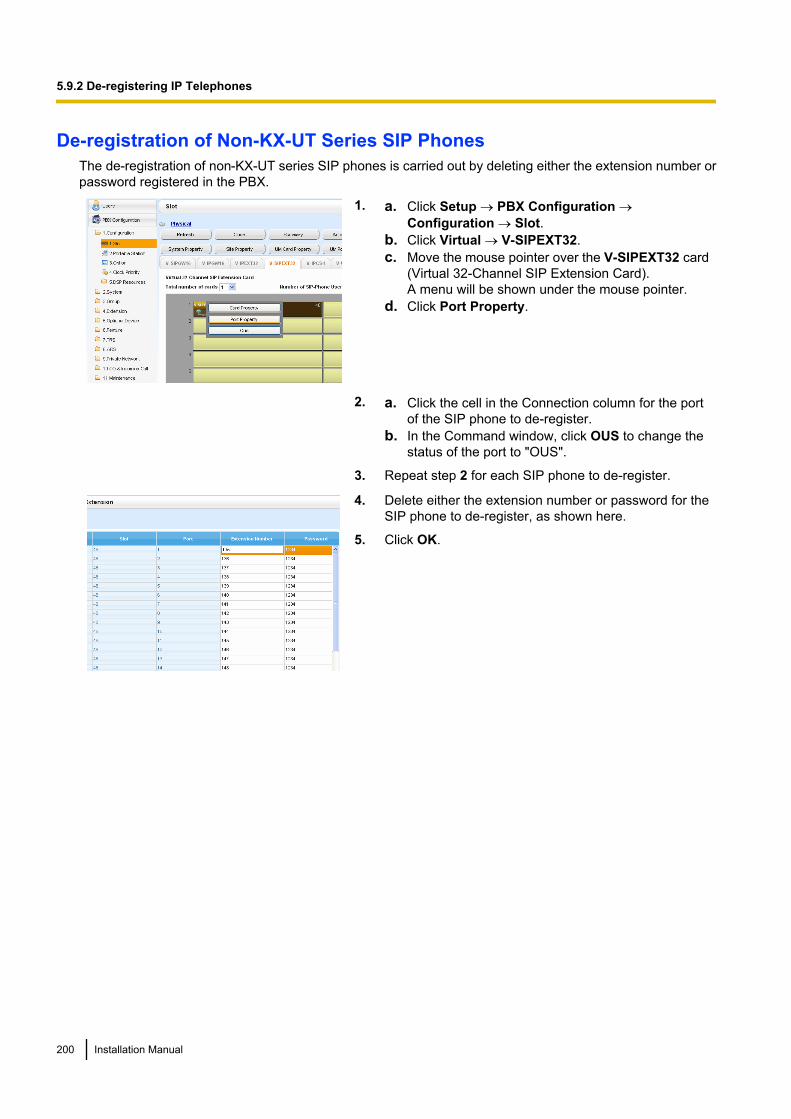
De-registration of Non-KX-UT Series SIP PhonesThe de-registration of non-KX-UT series SIP phones is carried out by deleting either the extension number orpassword registered in the PBX.
1. a. Click Setup ® PBX Configuration ®Configuration ® Slot.
b. Click Virtual ® V-SIPEXT32.c. Move the mouse pointer over the V-SIPEXT32 card
(Virtual 32-Channel SIP Extension Card).A menu will be shown under the mouse pointer.
d. Click Port Property.
2. a. Click the cell in the Connection column for the portof the SIP phone to de-register.
b. In the Command window, click OUS to change thestatus of the port to "OUS".
3. Repeat step 2 for each SIP phone to de-register.
4. Delete either the extension number or password for theSIP phone to de-register, as shown here.
5. Click OK.
200 Installation Manual
5.9.2 De-registering IP Telephones
5.10 Configuration of UsersThe system manages information about each user.Before programming other user settings, the following information must be configured for each user:• Extension number• Name• Unified Messaging mailbox• Web Maintenance Console login account (ID and password)Follow the procedure below to efficiently programme basic personal information by adding multiple users withthe Add Range feature.1. Click Setup ® PBX Configuration ® Configuration ® Slot.
Add one or more extension cards to the system, according to your equipment and needs. Extensionnumbers will be automatically created for each extension card that is added. For details about addingextension cards, refer to "9.1 PBX Configuration—Configuration—Slot" in the PC Programming Manual.
2. Click Setup ® PBX Configuration ® Extension.Enter an extension name for each extension number to be used. For details, refer to the following sectionsin the PC Programming Manual:• 12.1.1 PBX Configuration—Extension—Wired Extension—Extension Settings• 12.2.1 PBX Configuration—Extension—Portable Station—Extension Settings
NoteYou also can import extension names from a CSV file. For details refer to "6.6 Tool—Import" in thePC Programming Manual.
3. Click Setup ® Users ® User Profiles.You can create multiple user profiles automatically by using the Add Range feature for extension numbers.You can also set an extension number, first name, last name, Unified Messaging mailbox, and WebMaintenance Console login account for each user manually.For details, refer to "User Controls" in "8.1 Users—User Profiles" in the PC Programming Manual.For each user profile added using the Add Range feature, the following information is automaticallyassigned:• First Name: "Ext." + the extension number for the user (e.g., "Ext.101")• Last Name: The information entered in Extension Name for the extension in the Extension screen• Login ID: The extension number (i.e., if the extension is "101", the Login ID for the user will also be
"101")• Password: "PWD" + the extension number for the user (e.g., "PWD101")
4. If additional editing is required for users, settings can be configured on the following screens:a. To edit user information: Setup ® Users ® User Profilesb. To edit extension settings: Setup ® PBX Configuration ® Extensionc. To edit mailbox settings: Setup ® UM Configuration ® Mailbox Settings
NoteYou also can create mailboxes for Incoming Call Distribution Groups on the Mailbox Settingsscreen.
Installation Manual 201
5.10 Configuration of Users

202 Installation Manual
5.10 Configuration of Users

Section 6
Troubleshooting
This section provides information on the PBX andtelephone troubleshooting.
Installation Manual 203
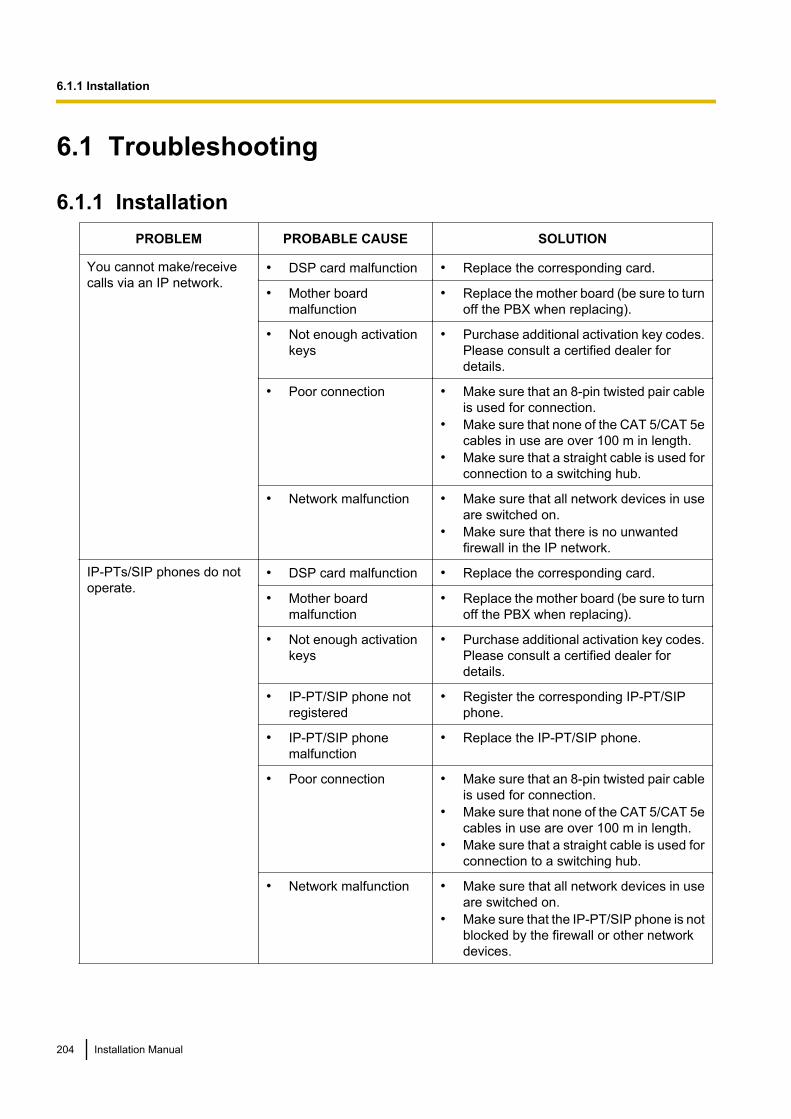
6.1 Troubleshooting
6.1.1 InstallationPROBLEM PROBABLE CAUSE SOLUTION
You cannot make/receivecalls via an IP network.
• DSP card malfunction • Replace the corresponding card.
• Mother boardmalfunction
• Replace the mother board (be sure to turnoff the PBX when replacing).
• Not enough activationkeys
• Purchase additional activation key codes.Please consult a certified dealer fordetails.
• Poor connection • Make sure that an 8-pin twisted pair cableis used for connection.
• Make sure that none of the CAT 5/CAT 5ecables in use are over 100 m in length.
• Make sure that a straight cable is used forconnection to a switching hub.
• Network malfunction • Make sure that all network devices in useare switched on.
• Make sure that there is no unwantedfirewall in the IP network.
IP-PTs/SIP phones do notoperate.
• DSP card malfunction • Replace the corresponding card.
• Mother boardmalfunction
• Replace the mother board (be sure to turnoff the PBX when replacing).
• Not enough activationkeys
• Purchase additional activation key codes.Please consult a certified dealer fordetails.
• IP-PT/SIP phone notregistered
• Register the corresponding IP-PT/SIPphone.
• IP-PT/SIP phonemalfunction
• Replace the IP-PT/SIP phone.
• Poor connection • Make sure that an 8-pin twisted pair cableis used for connection.
• Make sure that none of the CAT 5/CAT 5ecables in use are over 100 m in length.
• Make sure that a straight cable is used forconnection to a switching hub.
• Network malfunction • Make sure that all network devices in useare switched on.
• Make sure that the IP-PT/SIP phone is notblocked by the firewall or other networkdevices.
204 Installation Manual
6.1.1 Installation
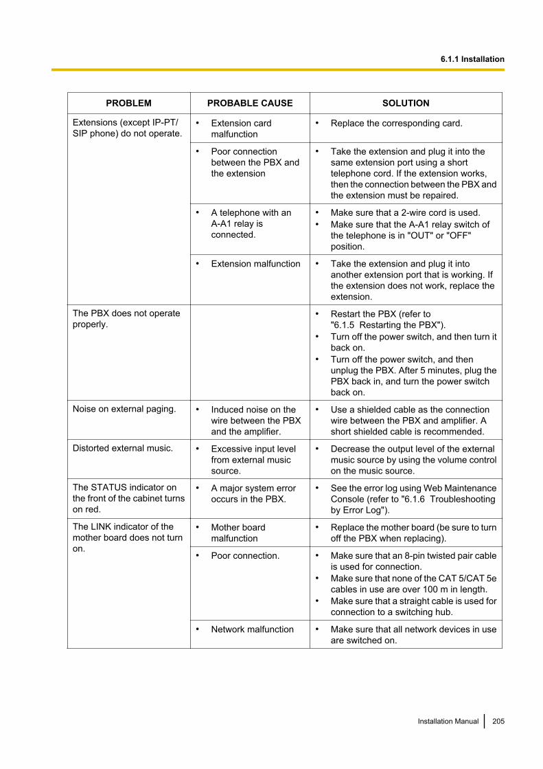
PROBLEM PROBABLE CAUSE SOLUTION
Extensions (except IP-PT/SIP phone) do not operate.
• Extension cardmalfunction
• Replace the corresponding card.
• Poor connectionbetween the PBX andthe extension
• Take the extension and plug it into thesame extension port using a shorttelephone cord. If the extension works,then the connection between the PBX andthe extension must be repaired.
• A telephone with anA-A1 relay isconnected.
• Make sure that a 2-wire cord is used.• Make sure that the A-A1 relay switch of
the telephone is in "OUT" or "OFF"position.
• Extension malfunction • Take the extension and plug it intoanother extension port that is working. Ifthe extension does not work, replace theextension.
The PBX does not operateproperly.
• Restart the PBX (refer to"6.1.5 Restarting the PBX").
• Turn off the power switch, and then turn itback on.
• Turn off the power switch, and thenunplug the PBX. After 5 minutes, plug thePBX back in, and turn the power switchback on.
Noise on external paging. • Induced noise on thewire between the PBXand the amplifier.
• Use a shielded cable as the connectionwire between the PBX and amplifier. Ashort shielded cable is recommended.
Distorted external music. • Excessive input levelfrom external musicsource.
• Decrease the output level of the externalmusic source by using the volume controlon the music source.
The STATUS indicator onthe front of the cabinet turnson red.
• A major system erroroccurs in the PBX.
• See the error log using Web MaintenanceConsole (refer to "6.1.6 Troubleshootingby Error Log").
The LINK indicator of themother board does not turnon.
• Mother boardmalfunction
• Replace the mother board (be sure to turnoff the PBX when replacing).
• Poor connection. • Make sure that an 8-pin twisted pair cableis used for connection.
• Make sure that none of the CAT 5/CAT 5ecables in use are over 100 m in length.
• Make sure that a straight cable is used forconnection to a switching hub.
• Network malfunction • Make sure that all network devices in useare switched on.
Installation Manual 205
6.1.1 Installation
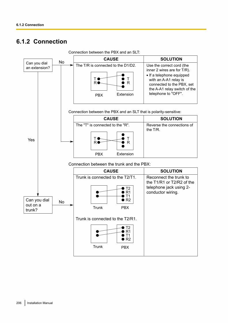
6.1.2 Connection
Connection between the trunk and the PBX:
CAUSE
Trunk is connected to the T2/T1.
SOLUTION
Reconnect the trunk to
the T1/R1 or T2/R2 of the
telephone jack using 2-
conductor wiring.T2R1T1R2
Trunk PBX
Trunk is connected to the T2/R1.
PBXTrunk
T2R1T1R2
NoCan you dial
out on a
trunk?
NoCan you dial
an extension?
Connection between the PBX and an SLT that is polarity-sensitive:
PBX
CAUSE
The "T" is connected to the "R".
SOLUTION
TR
TR
Extension
Reverse the connections of
the T/R.
Yes
Connection between the PBX and an SLT:
CAUSE SOLUTION
If a telephone equipped
with an A-A1 relay is
connected to the PBX, set
the A-A1 relay switch of the
telephone to "OFF".
Use the correct cord (the
inner 2 wires are for T/R).
PBX
The T/R is connected to the D1/D2.
TR
TR
Extension
206 Installation Manual
6.1.2 Connection
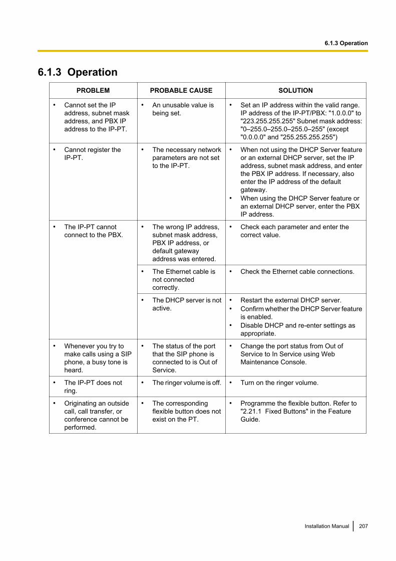
6.1.3 OperationPROBLEM PROBABLE CAUSE SOLUTION
• Cannot set the IPaddress, subnet maskaddress, and PBX IPaddress to the IP-PT.
• An unusable value isbeing set.
• Set an IP address within the valid range.IP address of the IP-PT/PBX: "1.0.0.0" to"223.255.255.255" Subnet mask address:"0–255.0–255.0–255.0–255" (except"0.0.0.0" and "255.255.255.255")
• Cannot register theIP-PT.
• The necessary networkparameters are not setto the IP-PT.
• When not using the DHCP Server featureor an external DHCP server, set the IPaddress, subnet mask address, and enterthe PBX IP address. If necessary, alsoenter the IP address of the defaultgateway.
• When using the DHCP Server feature oran external DHCP server, enter the PBXIP address.
• The IP-PT cannotconnect to the PBX.
• The wrong IP address,subnet mask address,PBX IP address, ordefault gatewayaddress was entered.
• Check each parameter and enter thecorrect value.
• The Ethernet cable isnot connectedcorrectly.
• Check the Ethernet cable connections.
• The DHCP server is notactive.
• Restart the external DHCP server.• Confirm whether the DHCP Server feature
is enabled.• Disable DHCP and re-enter settings as
appropriate.
• Whenever you try tomake calls using a SIPphone, a busy tone isheard.
• The status of the portthat the SIP phone isconnected to is Out ofService.
• Change the port status from Out ofService to In Service using WebMaintenance Console.
• The IP-PT does notring.
• The ringer volume is off. • Turn on the ringer volume.
• Originating an outsidecall, call transfer, orconference cannot beperformed.
• The correspondingflexible button does notexist on the PT.
• Programme the flexible button. Refer to"2.21.1 Fixed Buttons" in the FeatureGuide.
Installation Manual 207
6.1.3 Operation
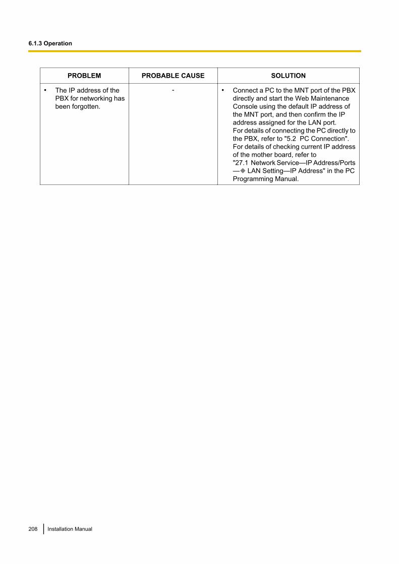
PROBLEM PROBABLE CAUSE SOLUTION
• The IP address of thePBX for networking hasbeen forgotten.
- • Connect a PC to the MNT port of the PBXdirectly and start the Web MaintenanceConsole using the default IP address ofthe MNT port, and then confirm the IPaddress assigned for the LAN port.For details of connecting the PC directly tothe PBX, refer to "5.2 PC Connection".For details of checking current IP addressof the mother board, refer to"27.1 Network Service—IP Address/Ports— LAN Setting—IP Address" in the PCProgramming Manual.
208 Installation Manual
6.1.3 Operation
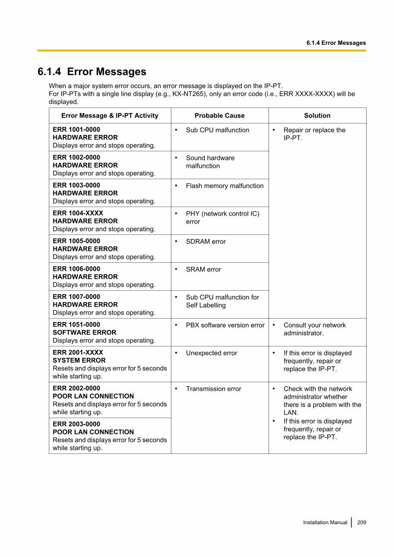
6.1.4 Error MessagesWhen a major system error occurs, an error message is displayed on the IP-PT.For IP-PTs with a single line display (e.g., KX-NT265), only an error code (i.e., ERR XXXX-XXXX) will bedisplayed.
Error Message & IP-PT Activity Probable Cause Solution
ERR 1001-0000HARDWARE ERRORDisplays error and stops operating.
• Sub CPU malfunction • Repair or replace theIP-PT.
ERR 1002-0000HARDWARE ERRORDisplays error and stops operating.
• Sound hardwaremalfunction
ERR 1003-0000HARDWARE ERRORDisplays error and stops operating.
• Flash memory malfunction
ERR 1004-XXXXHARDWARE ERRORDisplays error and stops operating.
• PHY (network control IC)error
ERR 1005-0000HARDWARE ERRORDisplays error and stops operating.
• SDRAM error
ERR 1006-0000HARDWARE ERRORDisplays error and stops operating.
• SRAM error
ERR 1007-0000HARDWARE ERRORDisplays error and stops operating.
• Sub CPU malfunction forSelf Labelling
ERR 1051-0000SOFTWARE ERRORDisplays error and stops operating.
• PBX software version error • Consult your networkadministrator.
ERR 2001-XXXXSYSTEM ERRORResets and displays error for 5 secondswhile starting up.
• Unexpected error • If this error is displayedfrequently, repair orreplace the IP-PT.
ERR 2002-0000POOR LAN CONNECTIONResets and displays error for 5 secondswhile starting up.
• Transmission error • Check with the networkadministrator whetherthere is a problem with theLAN.
• If this error is displayedfrequently, repair orreplace the IP-PT.
ERR 2003-0000POOR LAN CONNECTIONResets and displays error for 5 secondswhile starting up.
Installation Manual 209
6.1.4 Error Messages
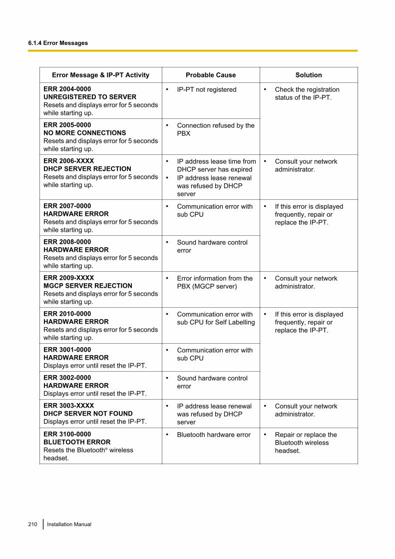
Error Message & IP-PT Activity Probable Cause Solution
ERR 2004-0000UNREGISTERED TO SERVERResets and displays error for 5 secondswhile starting up.
• IP-PT not registered • Check the registrationstatus of the IP-PT.
ERR 2005-0000NO MORE CONNECTIONSResets and displays error for 5 secondswhile starting up.
• Connection refused by thePBX
ERR 2006-XXXXDHCP SERVER REJECTIONResets and displays error for 5 secondswhile starting up.
• IP address lease time fromDHCP server has expired
• IP address lease renewalwas refused by DHCPserver
• Consult your networkadministrator.
ERR 2007-0000HARDWARE ERRORResets and displays error for 5 secondswhile starting up.
• Communication error withsub CPU
• If this error is displayedfrequently, repair orreplace the IP-PT.
ERR 2008-0000HARDWARE ERRORResets and displays error for 5 secondswhile starting up.
• Sound hardware controlerror
ERR 2009-XXXXMGCP SERVER REJECTIONResets and displays error for 5 secondswhile starting up.
• Error information from thePBX (MGCP server)
• Consult your networkadministrator.
ERR 2010-0000HARDWARE ERRORResets and displays error for 5 secondswhile starting up.
• Communication error withsub CPU for Self Labelling
• If this error is displayedfrequently, repair orreplace the IP-PT.
ERR 3001-0000HARDWARE ERRORDisplays error until reset the IP-PT.
• Communication error withsub CPU
ERR 3002-0000HARDWARE ERRORDisplays error until reset the IP-PT.
• Sound hardware controlerror
ERR 3003-XXXXDHCP SERVER NOT FOUNDDisplays error until reset the IP-PT.
• IP address lease renewalwas refused by DHCPserver
• Consult your networkadministrator.
ERR 3100-0000BLUETOOTH ERRORResets the Bluetooth® wirelessheadset.
• Bluetooth hardware error • Repair or replace theBluetooth wirelessheadset.
210 Installation Manual
6.1.4 Error Messages
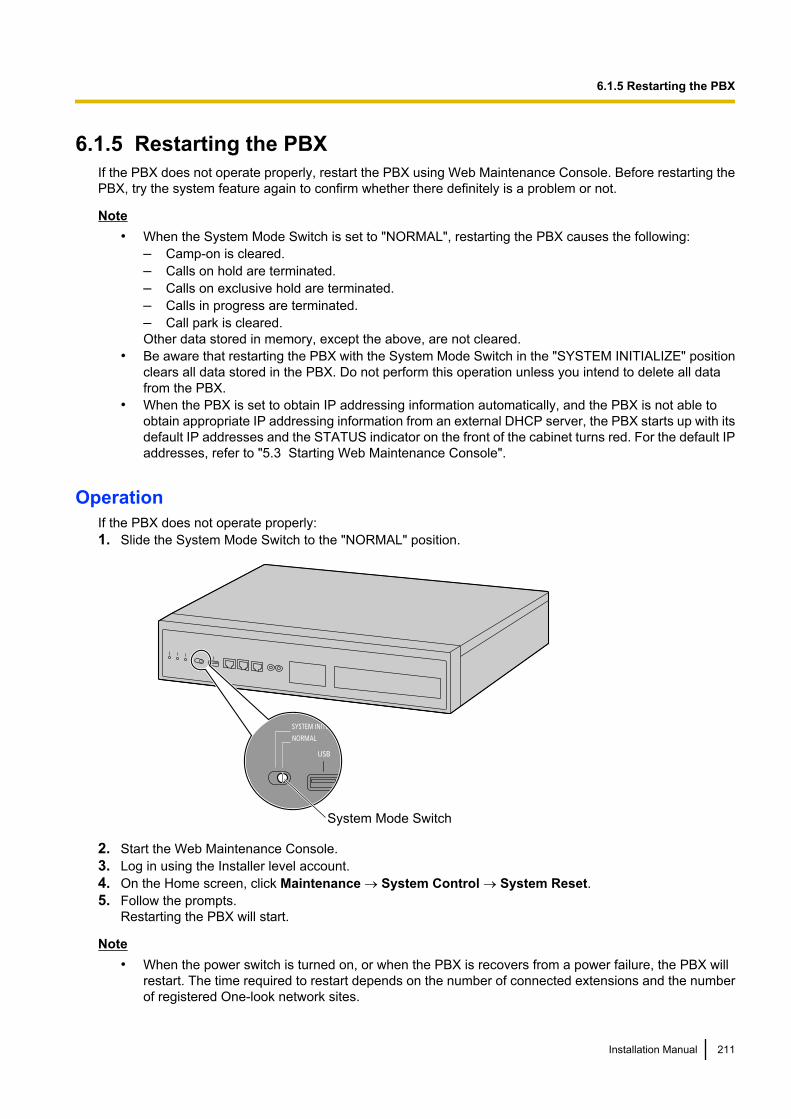
6.1.5 Restarting the PBXIf the PBX does not operate properly, restart the PBX using Web Maintenance Console. Before restarting thePBX, try the system feature again to confirm whether there definitely is a problem or not.
Note• When the System Mode Switch is set to "NORMAL", restarting the PBX causes the following:
– Camp-on is cleared.– Calls on hold are terminated.– Calls on exclusive hold are terminated.– Calls in progress are terminated.– Call park is cleared.Other data stored in memory, except the above, are not cleared.
• Be aware that restarting the PBX with the System Mode Switch in the "SYSTEM INITIALIZE" positionclears all data stored in the PBX. Do not perform this operation unless you intend to delete all datafrom the PBX.
• When the PBX is set to obtain IP addressing information automatically, and the PBX is not able toobtain appropriate IP addressing information from an external DHCP server, the PBX starts up with itsdefault IP addresses and the STATUS indicator on the front of the cabinet turns red. For the default IPaddresses, refer to "5.3 Starting Web Maintenance Console".
OperationIf the PBX does not operate properly:1. Slide the System Mode Switch to the "NORMAL" position.
System Mode Switch
2. Start the Web Maintenance Console.3. Log in using the Installer level account.4. On the Home screen, click Maintenance ® System Control ® System Reset.5. Follow the prompts.
Restarting the PBX will start.
Note• When the power switch is turned on, or when the PBX is recovers from a power failure, the PBX will
restart. The time required to restart depends on the number of connected extensions and the numberof registered One-look network sites.
Installation Manual 211
6.1.5 Restarting the PBX
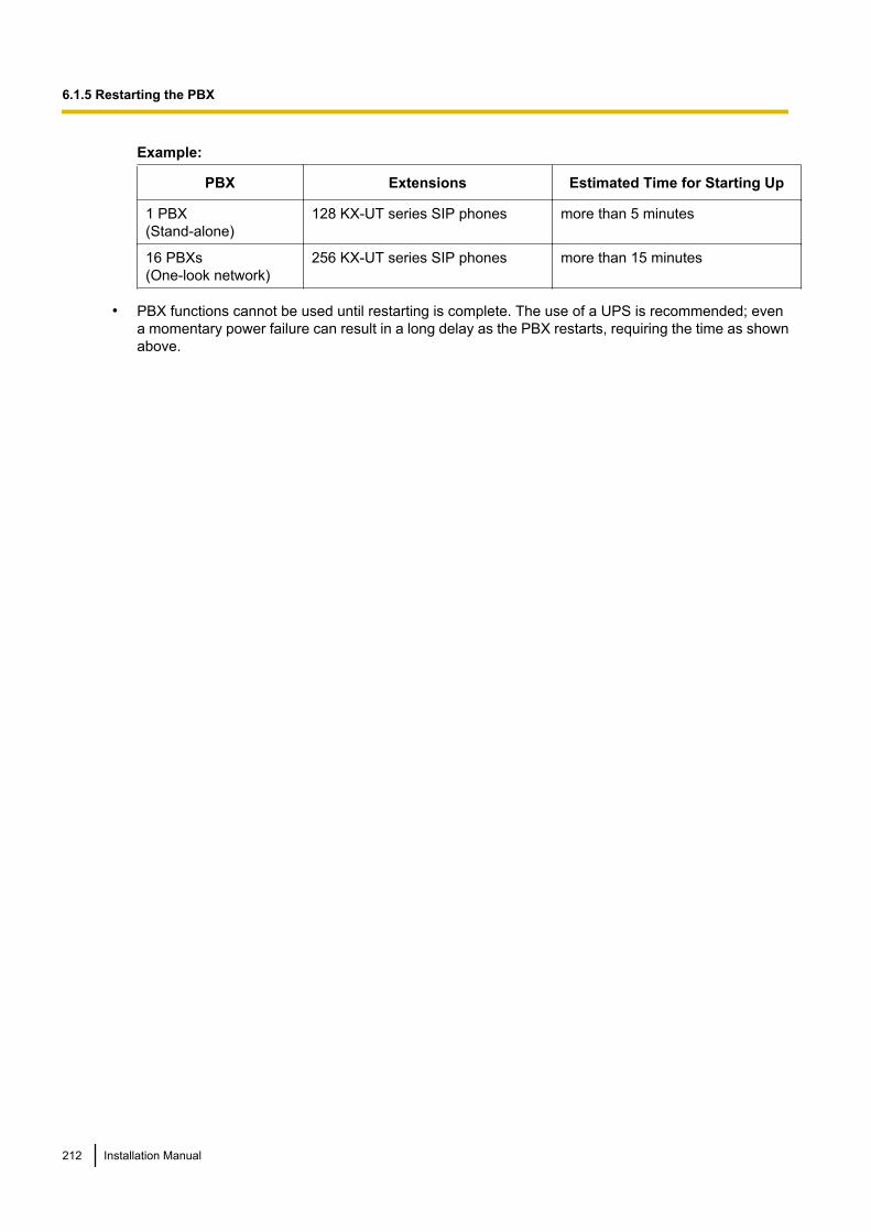
Example:
PBX Extensions Estimated Time for Starting Up
1 PBX(Stand-alone)
128 KX-UT series SIP phones more than 5 minutes
16 PBXs(One-look network)
256 KX-UT series SIP phones more than 15 minutes
• PBX functions cannot be used until restarting is complete. The use of a UPS is recommended; evena momentary power failure can result in a long delay as the PBX restarts, requiring the time as shownabove.
212 Installation Manual
6.1.5 Restarting the PBX
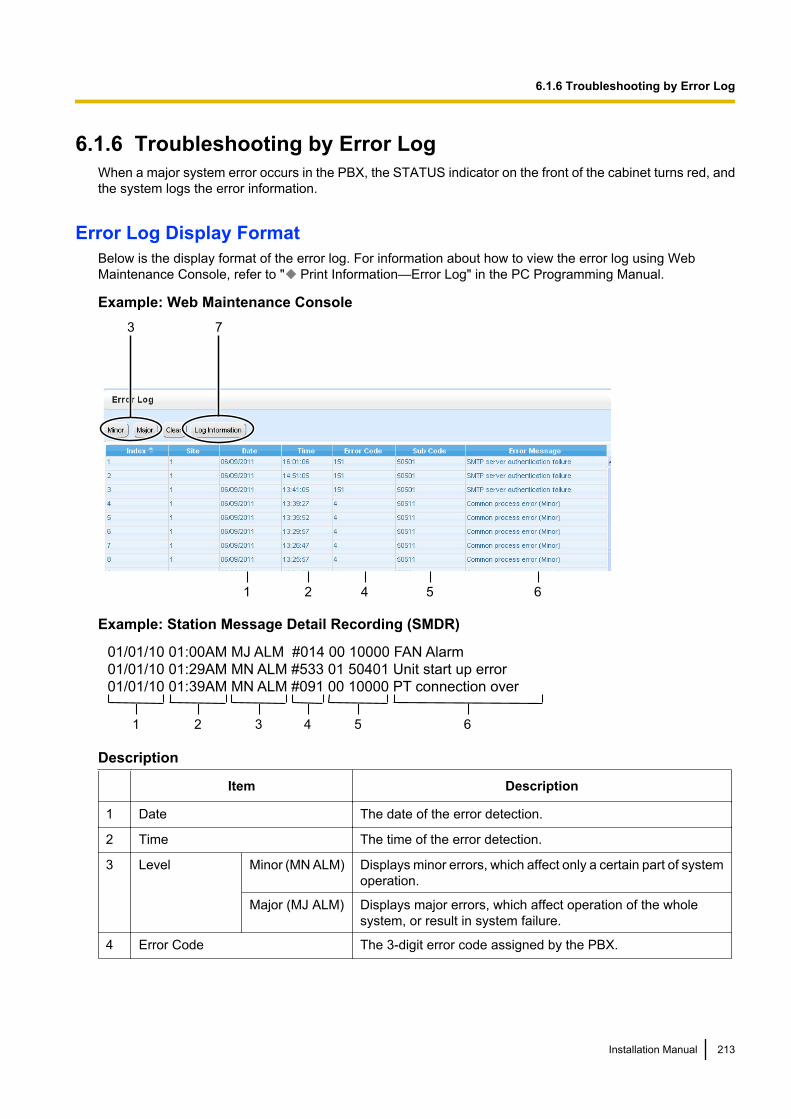
6.1.6 Troubleshooting by Error LogWhen a major system error occurs in the PBX, the STATUS indicator on the front of the cabinet turns red, andthe system logs the error information.
Error Log Display FormatBelow is the display format of the error log. For information about how to view the error log using WebMaintenance Console, refer to " Print Information—Error Log" in the PC Programming Manual.
Example: Web Maintenance Console3 7
1 2 4 5 6
Example: Station Message Detail Recording (SMDR)
01/01/10 01:00AM MJ ALM #014 00 10000 FAN Alarm
01/01/10 01:29AM MN ALM #533 01 50401 Unit start up error
01/01/10 01:39AM MN ALM #091 00 10000 PT connection over
1 2 3 4 5 6
Description
Item Description
1 Date The date of the error detection.
2 Time The time of the error detection.
3 Level Minor (MN ALM) Displays minor errors, which affect only a certain part of systemoperation.
Major (MJ ALM) Displays major errors, which affect operation of the wholesystem, or result in system failure.
4 Error Code The 3-digit error code assigned by the PBX.
Installation Manual 213
6.1.6 Troubleshooting by Error Log
Item Description
5 Sub Code SMDR:The 8-digit sub code of the relevant hardware (BBWXYYZZ).Web Maintenance Console:The 6-digit sub code of the relevant hardware (WXYYZZ). (Thesite number of the PBX can be confirmed in the Site column ofthe Error Log.)
• BB: Site ID (00 to 15)– Corresponds to site numbers of PBXs in the One-look
network (1 to 16)• W: Slot type
– Physical slot: " " (blank)– Virtual slot: "*" (asterisk)
• X: (1: Unit number, 5: Other than PBX process code)
When X = 1• YY: Slot number
– Physical slot: 00 to 05(00: Mother board slot; 01 to 05: Optional service cardslots)
– Virtual slot: 01 to 52(01 to 16: Virtual trunk slots; 17 to 52: Virtual extensionslots)
• ZZ: Port number– For optional service cards:
The port number (01 to XX) will be displayed.
When X = 5• YY: Process code• ZZ: Process number (determined by each process)
NoteWhen there is no parameter for slot and port number, YYand ZZ will be displayed as "00".Example: Sub code for the mother board = "01 10000"
6 Error Message A description of the error.
7 Log Information Displays probable causes of the errors and their solutions.
214 Installation Manual
6.1.6 Troubleshooting by Error Log
Section 7
Appendix
This section provides information on using the PBX witha VoIP network, the ports used by the PBX, and PBXRegion Suffix Codes and Areas.
Installation Manual 215
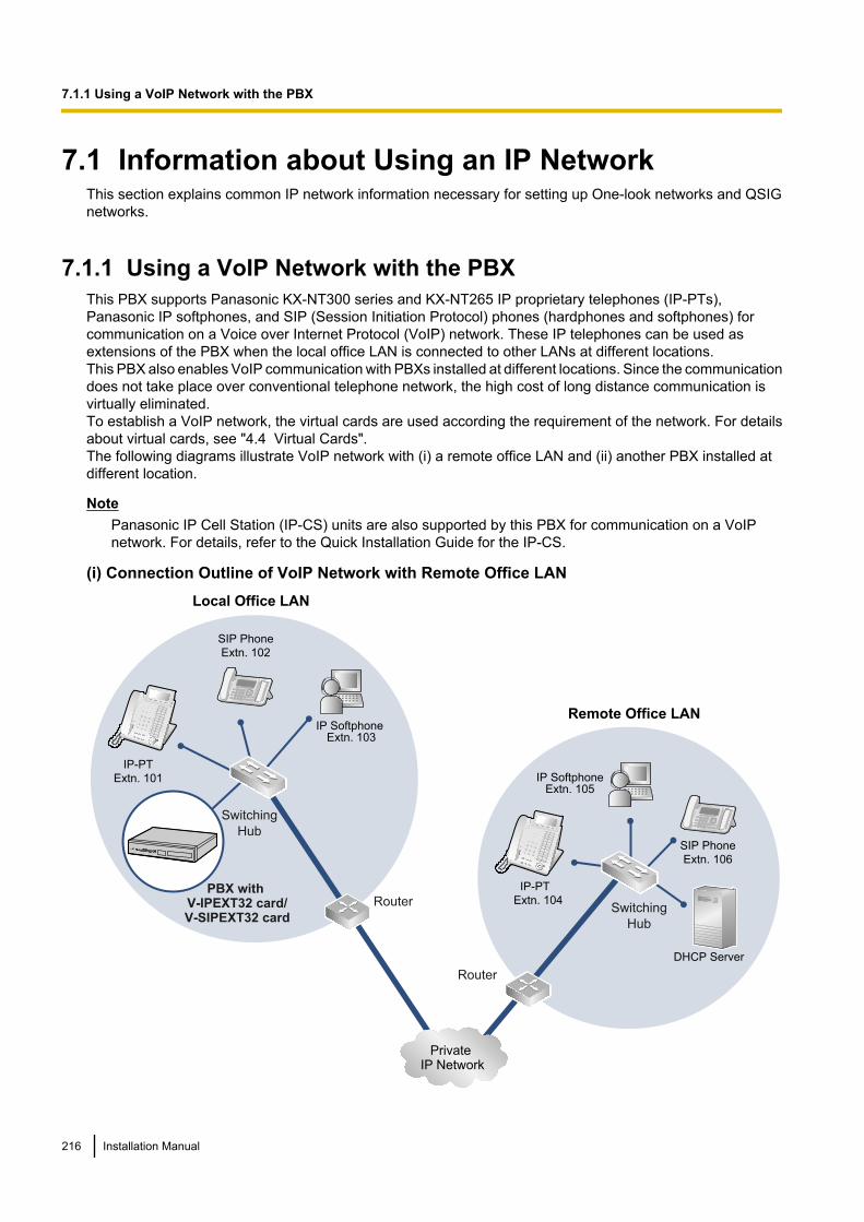
7.1 Information about Using an IP NetworkThis section explains common IP network information necessary for setting up One-look networks and QSIGnetworks.
7.1.1 Using a VoIP Network with the PBXThis PBX supports Panasonic KX-NT300 series and KX-NT265 IP proprietary telephones (IP-PTs),Panasonic IP softphones, and SIP (Session Initiation Protocol) phones (hardphones and softphones) forcommunication on a Voice over Internet Protocol (VoIP) network. These IP telephones can be used asextensions of the PBX when the local office LAN is connected to other LANs at different locations.This PBX also enables VoIP communication with PBXs installed at different locations. Since the communicationdoes not take place over conventional telephone network, the high cost of long distance communication isvirtually eliminated.To establish a VoIP network, the virtual cards are used according the requirement of the network. For detailsabout virtual cards, see "4.4 Virtual Cards".The following diagrams illustrate VoIP network with (i) a remote office LAN and (ii) another PBX installed atdifferent location.
NotePanasonic IP Cell Station (IP-CS) units are also supported by this PBX for communication on a VoIPnetwork. For details, refer to the Quick Installation Guide for the IP-CS.
(i) Connection Outline of VoIP Network with Remote Office LAN
SIP Phone
Extn. 102
IP-PT
Extn. 101
DHCP Server
Remote Office LAN
Local Office LAN
Router
Switching
Hub
PBX with
V-IPEXT32 card/
V-SIPEXT32 card
IP Softphone Extn. 103
Private
IP Network
IP-PT
Extn. 104Switching
Hub
IP SoftphoneExtn. 105
Router
SIP Phone
Extn. 106
216 Installation Manual
7.1.1 Using a VoIP Network with the PBX
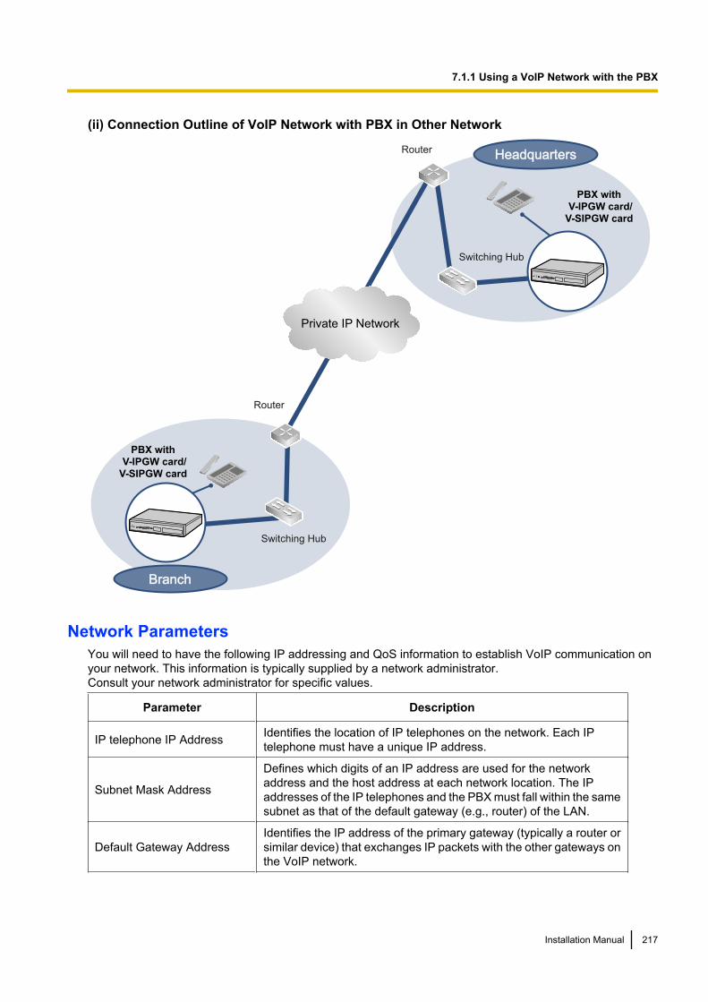
(ii) Connection Outline of VoIP Network with PBX in Other Network
Private IP Network
Router
Switching Hub
Router
Switching Hub
PBX with
V-IPGW card/
V-SIPGW card
BranchBranch
HeadquartersHeadquarters
PBX with
V-IPGW card/
V-SIPGW card
Network ParametersYou will need to have the following IP addressing and QoS information to establish VoIP communication onyour network. This information is typically supplied by a network administrator.Consult your network administrator for specific values.
Parameter Description
IP telephone IP Address Identifies the location of IP telephones on the network. Each IPtelephone must have a unique IP address.
Subnet Mask Address
Defines which digits of an IP address are used for the networkaddress and the host address at each network location. The IPaddresses of the IP telephones and the PBX must fall within the samesubnet as that of the default gateway (e.g., router) of the LAN.
Default Gateway AddressIdentifies the IP address of the primary gateway (typically a router orsimilar device) that exchanges IP packets with the other gateways onthe VoIP network.
Installation Manual 217
7.1.1 Using a VoIP Network with the PBX
Parameter Description
PBX IP Address Identifies the location of the PBX in the network during VoIPcommunications.
VLAN IDIdentifies the ID of the logical segment within the corporate LAN,through which voice packets from IP telephones travel. For details,refer to "7.1.3 VLAN (Virtual LAN)".
DiffServ (DS)Identifies the value for the DS field in the header of IP packets, whichdetermines the priority given to packets travelling from IP telephones.For details, refer to "5.8.3 Setting Diffserv Parameters".
Types of IP NetworkThe speech quality depends on the type of IP network in use. Managed IP networks provide better speechquality compared to unmanaged networks such as satellite communications, where quality of service cannotbe guaranteed.
Examples of recommended IP networks• Digital Leased Line• IP-VPN (Virtual Private Network)• Frame Relay
Not recommended• Satellite communications (Very Small Aperture
Terminal system [VSAT], etc.)
Note• Peer-to-peer calls between IP telephones installed at different locations may not be possible if packet
communication cannot be established between the respective networks. In this case, you need toconfigure the network settings (e.g., a VPN router when using an IP-VPN) to establish packetcommunication.
• Unlike an IP-VPN, which is set up over a network provider’s own IP network, an Internet VPN is set upover the Internet. Internet VPNs are not recommended for VoIP communication because transmissiondelays and loss of data are likely to occur.
• If multiple Slave units exist in a One-look network using IP-VPN, each Slave unit must havepeer-to-peer communication enabled. Therefore, inform your network administrator and make sure thatthe network supports this requirement.
218 Installation Manual
7.1.1 Using a VoIP Network with the PBX
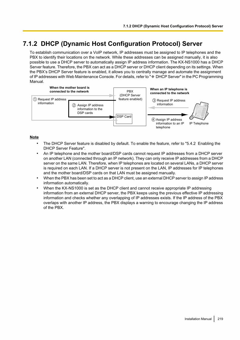
7.1.2 DHCP (Dynamic Host Configuration Protocol) ServerTo establish communication over a VoIP network, IP addresses must be assigned to IP telephones and thePBX to identify their locations on the network. While these addresses can be assigned manually, it is alsopossible to use a DHCP server to automatically assign IP address information. The KX-NS1000 has a DHCPServer feature. Therefore, the PBX can act as a DHCP server or DHCP client depending on its settings. Whenthe PBX’s DHCP Server feature is enabled, it allows you to centrally manage and automate the assignmentof IP addresses with Web Maintenance Console. For details, refer to " DHCP Server" in the PC ProgrammingManual.
Assign IP address
information to an IP
telephone
When the mother board is
connected to the networkWhen an IP telephone is
connected to the network
Request IP address
information
1
Assign IP address
information to the
DSP cards
2
Request IP address
information3
4
PBX
(DHCP Server
feature enabled)
DSP Card
IP Telephone
Note• The DHCP Server feature is disabled by default. To enable the feature, refer to "5.4.2 Enabling the
DHCP Server Feature".• An IP telephone and the mother board/DSP cards cannot request IP addresses from a DHCP server
on another LAN (connected through an IP network). They can only receive IP addresses from a DHCPserver on the same LAN. Therefore, when IP telephones are located on several LANs, a DHCP serveris required on each LAN. If a DHCP server is not present on the LAN, IP addresses for IP telephonesand the mother board/DSP cards on that LAN must be assigned manually.
• When the PBX has been set to act as a DHCP client, use an external DHCP server to assign IP addressinformation automatically.
• When the KX-NS1000 is set as the DHCP client and cannot receive appropriate IP addressinginformation from an external DHCP server, the PBX keeps using the previous effective IP addressinginformation and checks whether any overlapping of IP addresses exists. If the IP address of the PBXoverlaps with another IP address, the PBX displays a warning to encourage changing the IP addressof the PBX.
Installation Manual 219
7.1.2 DHCP (Dynamic Host Configuration Protocol) Server
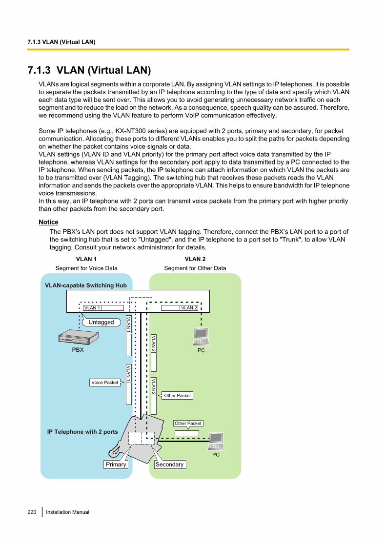
7.1.3 VLAN (Virtual LAN)VLANs are logical segments within a corporate LAN. By assigning VLAN settings to IP telephones, it is possibleto separate the packets transmitted by an IP telephone according to the type of data and specify which VLANeach data type will be sent over. This allows you to avoid generating unnecessary network traffic on eachsegment and to reduce the load on the network. As a consequence, speech quality can be assured. Therefore,we recommend using the VLAN feature to perform VoIP communication effectively.
Some IP telephones (e.g., KX-NT300 series) are equipped with 2 ports, primary and secondary, for packetcommunication. Allocating these ports to different VLANs enables you to split the paths for packets dependingon whether the packet contains voice signals or data.VLAN settings (VLAN ID and VLAN priority) for the primary port affect voice data transmitted by the IPtelephone, whereas VLAN settings for the secondary port apply to data transmitted by a PC connected to theIP telephone. When sending packets, the IP telephone can attach information on which VLAN the packets areto be transmitted over (VLAN Tagging). The switching hub that receives these packets reads the VLANinformation and sends the packets over the appropriate VLAN. This helps to ensure bandwidth for IP telephonevoice transmissions.In this way, an IP telephone with 2 ports can transmit voice packets from the primary port with higher prioritythan other packets from the secondary port.
NoticeThe PBX’s LAN port does not support VLAN tagging. Therefore, connect the PBX’s LAN port to a port ofthe switching hub that is set to "Untagged", and the IP telephone to a port set to "Trunk", to allow VLANtagging. Consult your network administrator for details.
PBX
IP Telephone with 2 ports
VLA
N 1
VLA
N 1
VLAN 1
VLA
N 2
VLAN 2
VLAN 1
Segment for Voice Data
VLAN 2
Segment for Other Data
Voice Packet
Other Packet
PC
PC
Other Packet
VLA
N 2
VLAN-capable Switching Hub
Primary Secondary
Untagged
220 Installation Manual
7.1.3 VLAN (Virtual LAN)
Note• This VLAN feature complies with IEEE (Institute of Electrical and Electronics Engineers) 802.1Q.• The PBX receives VLAN settings only from the connected switching hub. Therefore, VLAN settings for
the PBX must be assigned at the switching hub.• When using the VLAN feature on the network, make sure that the main unit is connected to a layer 2
switch that is IEEE 802.1Q compliant, and that is configured for VLANs. In addition, the port of theswitching hub to which the card is connected must be set to "Untagged". Consult your networkadministrator for details.
• When using the VLAN feature on the network, make sure that the switching hub to be connected isIEEE 802.1Q compliant and is configured for VLANs. In addition, the port of a switching hub that theIP telephone is connected to must be set to "Trunk" port, to allow VLAN tagging. Consult your networkadministrator for details.
• Some PC LAN cards allow VLAN settings to be assigned. However, when using a PC connected to anIP telephone with 2 ports, the VLAN settings for PC communications must be assigned only to thesecondary port of the IP telephone. Any VLAN settings assigned to the PC LAN card must be disabled.These settings can usually be identified by "802.1Q", "802.1p", or "VLAN" in their name.
• If you are using an IP telephone with a primary port only (e.g., KX-NT265), a PC cannot be connectedto the IP telephone.
7.1.4 Jitter BufferWhen voice signals are packetised and transmitted, individual packets can take different paths through thenetwork and arrive at the destination at varied timings. This is referred to as "jitter", and it can cause degradationin speech quality. To compensate for jitter problems, the "jitter buffer" accumulates the packets temporarily forprocessing.To set the size of the jitter buffer, refer to "9.5 PBX Configuration—Configuration—Slot—Site Property—VoIP-DSP Options" in the PC Programming Manual.
7.1.5 Voice Activity Detection (VAD)VAD conserves bandwidth by detecting silent periods during a call and suppressing the packets of silence frombeing sent to the network. This feature can be enabled or disabled for codec G.711.To configure the VAD feature, refer to the appropriate section in the PC Programming Manual.
Installation Manual 221
7.1.5 Voice Activity Detection (VAD)
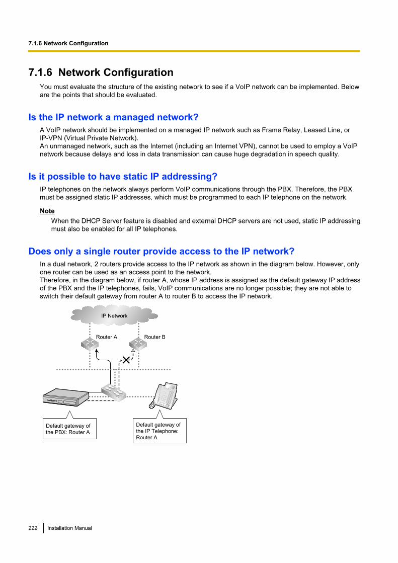
7.1.6 Network ConfigurationYou must evaluate the structure of the existing network to see if a VoIP network can be implemented. Beloware the points that should be evaluated.
Is the IP network a managed network?A VoIP network should be implemented on a managed IP network such as Frame Relay, Leased Line, orIP-VPN (Virtual Private Network).An unmanaged network, such as the Internet (including an Internet VPN), cannot be used to employ a VoIPnetwork because delays and loss in data transmission can cause huge degradation in speech quality.
Is it possible to have static IP addressing?IP telephones on the network always perform VoIP communications through the PBX. Therefore, the PBXmust be assigned static IP addresses, which must be programmed to each IP telephone on the network.
NoteWhen the DHCP Server feature is disabled and external DHCP servers are not used, static IP addressingmust also be enabled for all IP telephones.
Does only a single router provide access to the IP network?In a dual network, 2 routers provide access to the IP network as shown in the diagram below. However, onlyone router can be used as an access point to the network.Therefore, in the diagram below, if router A, whose IP address is assigned as the default gateway IP addressof the PBX and the IP telephones, fails, VoIP communications are no longer possible; they are not able toswitch their default gateway from router A to router B to access the IP network.
IP Network
Router A Router B
Default gateway of
the PBX: Router A
Default gateway of
the IP Telephone:
Router A
222 Installation Manual
7.1.6 Network Configuration
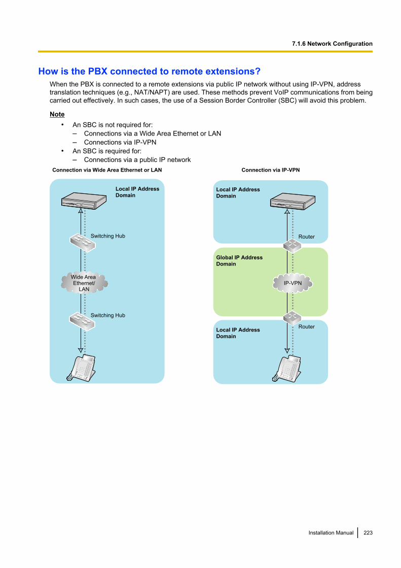
How is the PBX connected to remote extensions?When the PBX is connected to a remote extensions via public IP network without using IP-VPN, addresstranslation techniques (e.g., NAT/NAPT) are used. These methods prevent VoIP communications from beingcarried out effectively. In such cases, the use of a Session Border Controller (SBC) will avoid this problem.
Note• An SBC is not required for:
– Connections via a Wide Area Ethernet or LAN– Connections via IP-VPN
• An SBC is required for:– Connections via a public IP network
Router
Global IP Address
Domain
Local IP Address
Domain
Local IP Address
Domain
Connection via IP-VPN
IP-VPN
Router
Switching Hub
Switching Hub
Local IP Address
Domain
Connection via Wide Area Ethernet or LAN
Wide Area Ethernet/
LAN
Installation Manual 223
7.1.6 Network Configuration
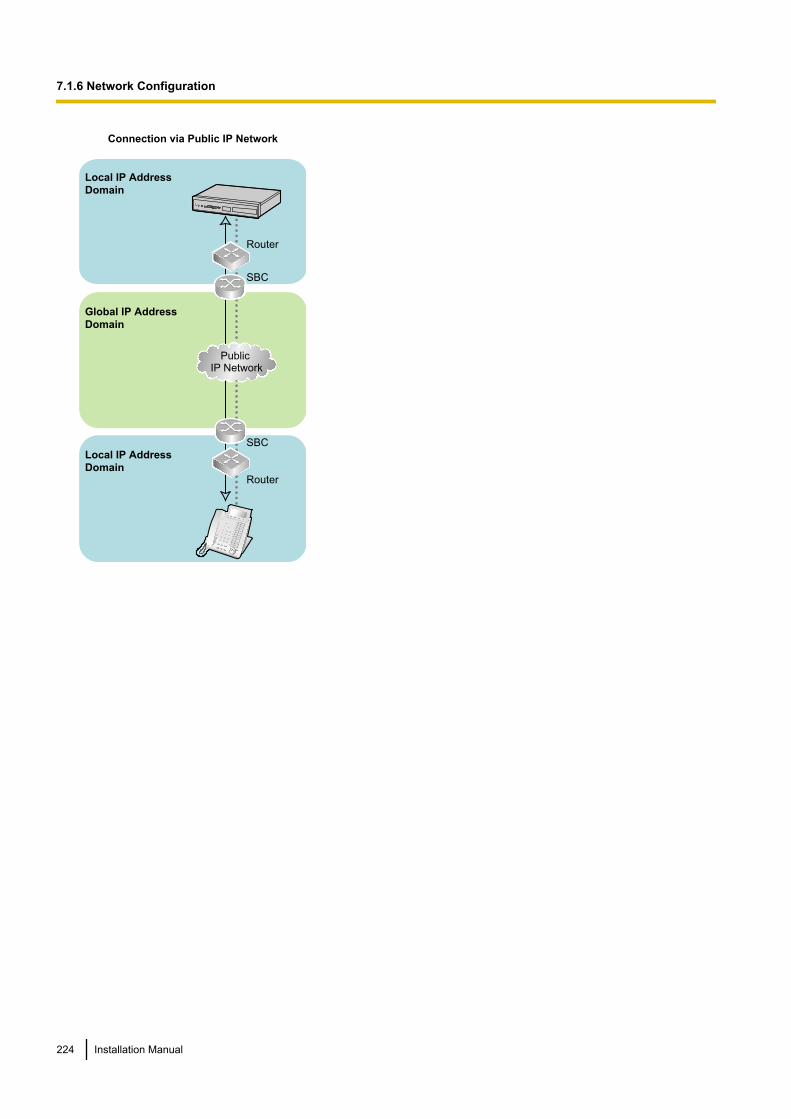
Router
Global IP Address
Domain
Local IP Address
Domain
Local IP Address
Domain
Connection via Public IP Network
Public IP Network
SBC
Router
SBC
224 Installation Manual
7.1.6 Network Configuration
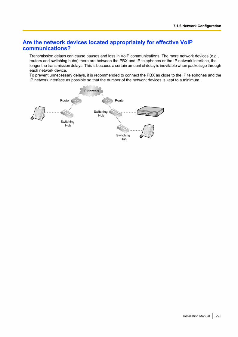
Are the network devices located appropriately for effective VoIPcommunications?
Transmission delays can cause pauses and loss in VoIP communications. The more network devices (e.g.,routers and switching hubs) there are between the PBX and IP telephones or the IP network interface, thelonger the transmission delays. This is because a certain amount of delay is inevitable when packets go througheach network device.To prevent unnecessary delays, it is recommended to connect the PBX as close to the IP telephones and theIP network interface as possible so that the number of the network devices is kept to a minimum.
IP Network
RouterRouter
Switching
Hub
Switching
Hub
Switching
Hub
Installation Manual 225
7.1.6 Network Configuration
7.1.7 Network DevicesYou must evaluate the network devices that are used in the existing network to see if a VoIP network can beimplemented. Below are the points that should be evaluated.
Can the firewall pass packets appropriately?If the VoIP network contains a firewall, the firewall must be configured appropriately to allow VoIP packets topass through the network without being blocked by filtering. For details about the protocols and port numbersthat the PBX uses for VoIP communication, refer to "7.5 Port Security".The ports for which you need to configure the firewall may vary depending on the network conditions.For more information, consult your network administrator.
Are layer 2 or higher switches used?Use of repeater hubs can increase the network load, and therefore may result in degradation in speech quality.To ensure high speech quality, use only layer 2 or higher switches. Use of layer 2 or higher switches is alsostrongly recommended for connecting IP telephones.
NoteNote that the port of the switching hub that connects to the mother board should be set to operate under"Auto Negotiation" mode.
Does all equipment on the LAN support 1000BASE-T connection?To use the Gigabit Ethernet feature for the LAN, all equipment on the LAN must support 1000BASE-T. Formore information, consult your network administrator.
Are Category 5 (CAT 5) or higher cables used for 10BASE-T/100BASE-TX?When connecting network devices, make sure to use CAT 5 or higher cables for 10BASE-T/100BASE-TXconnection. If other types of cables are used, communication may not be carried out normally.
Are Enhanced Category 5 (CAT 5e) or higher cables used for 1000BASE-T?When connecting network devices, make sure to use CAT 5e or higher cables for 1000BASE-T. If other typesof cables are used, communication may not be carried out normally.
226 Installation Manual
7.1.7 Network Devices
7.1.8 QoS (Quality of Service)Some routers permit the configuration of priority control features. This allows the router to give higher priorityto voice packets and lower the rate of loss and delays during transmissions, hence improving speech quality.It is strongly recommended that you use this feature, especially in networks where traffic is heavy.
Typically, a router identifies what packets to pass in priority by checking the value in the ToS field of the headerof IP packets. The V-IPGW16 card has the ability to set the ToS field of outgoing voice packets. When the cardis appropriately configured, the router can give voice packets from the card higher priority.Consult your network administrator when setting the ToS field, as the setting value must conform to therouter’s specifications.
Note• Some switches also permit the configuration of priority control features. For more information, consult
your network administrator.• To adjust the value in the ToS field, refer to "9.11 PBX Configuration—Configuration—Slot—V-IPGW16
—Shelf Property" in the PC Programming Manual.
Installation Manual 227
7.1.8 QoS (Quality of Service)
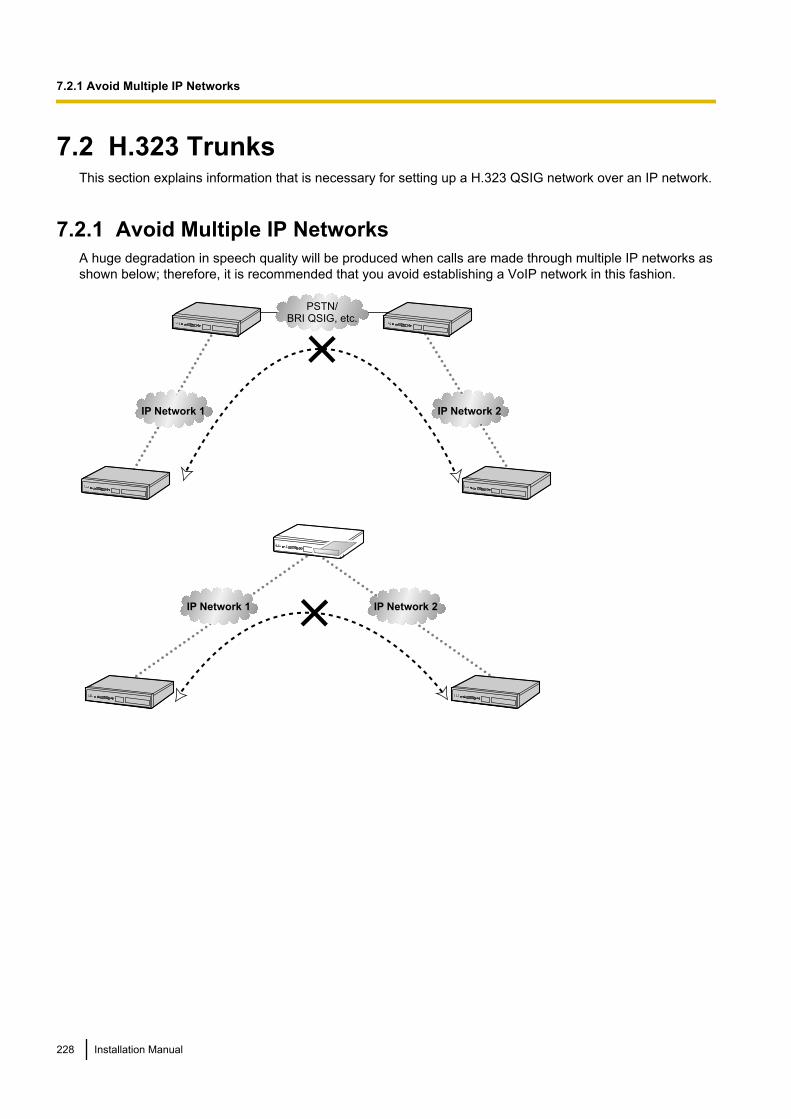
7.2 H.323 TrunksThis section explains information that is necessary for setting up a H.323 QSIG network over an IP network.
7.2.1 Avoid Multiple IP NetworksA huge degradation in speech quality will be produced when calls are made through multiple IP networks asshown below; therefore, it is recommended that you avoid establishing a VoIP network in this fashion.
IP Network 1 IP Network 2
PSTN/BRI QSIG, etc.
IP Network 1 IP Network 2
228 Installation Manual
7.2.1 Avoid Multiple IP Networks
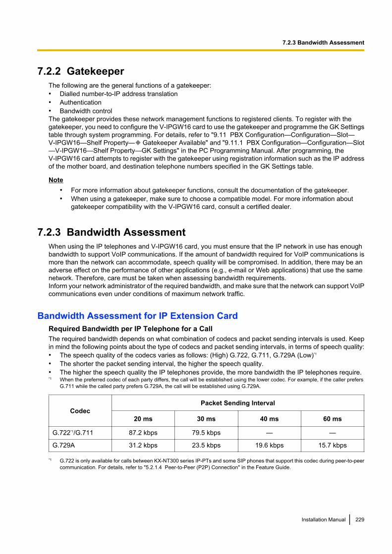
7.2.2 GatekeeperThe following are the general functions of a gatekeeper:• Dialled number-to-IP address translation• Authentication• Bandwidth controlThe gatekeeper provides these network management functions to registered clients. To register with thegatekeeper, you need to configure the V-IPGW16 card to use the gatekeeper and programme the GK Settingstable through system programming. For details, refer to "9.11 PBX Configuration—Configuration—Slot—V-IPGW16—Shelf Property— Gatekeeper Available" and "9.11.1 PBX Configuration—Configuration—Slot—V-IPGW16—Shelf Property—GK Settings" in the PC Programming Manual. After programming, theV-IPGW16 card attempts to register with the gatekeeper using registration information such as the IP addressof the mother board, and destination telephone numbers specified in the GK Settings table.
Note• For more information about gatekeeper functions, consult the documentation of the gatekeeper.• When using a gatekeeper, make sure to choose a compatible model. For more information about
gatekeeper compatibility with the V-IPGW16 card, consult a certified dealer.
7.2.3 Bandwidth AssessmentWhen using the IP telephones and V-IPGW16 card, you must ensure that the IP network in use has enoughbandwidth to support VoIP communications. If the amount of bandwidth required for VoIP communications ismore than the network can accommodate, speech quality will be compromised. In addition, there may be anadverse effect on the performance of other applications (e.g., e-mail or Web applications) that use the samenetwork. Therefore, care must be taken when assessing bandwidth requirements.Inform your network administrator of the required bandwidth, and make sure that the network can support VoIPcommunications even under conditions of maximum network traffic.
Bandwidth Assessment for IP Extension CardRequired Bandwidth per IP Telephone for a CallThe required bandwidth depends on what combination of codecs and packet sending intervals is used. Keepin mind the following points about the type of codecs and packet sending intervals, in terms of speech quality:• The speech quality of the codecs varies as follows: (High) G.722, G.711, G.729A (Low)*1
• The shorter the packet sending interval, the higher the speech quality.• The higher the speech quality the IP telephones provide, the more bandwidth the IP telephones require.*1 When the preferred codec of each party differs, the call will be established using the lower codec. For example, if the caller prefers
G.711 while the called party prefers G.729A, the call will be established using G.729A.
CodecPacket Sending Interval
20 ms 30 ms 40 ms 60 ms
G.722*1/G.711 87.2 kbps 79.5 kbps — —
G.729A 31.2 kbps 23.5 kbps 19.6 kbps 15.7 kbps
*1 G.722 is only available for calls between KX-NT300 series IP-PTs and some SIP phones that support this codec during peer-to-peercommunication. For details, refer to "5.2.1.4 Peer-to-Peer (P2P) Connection" in the Feature Guide.
Installation Manual 229
7.2.3 Bandwidth Assessment
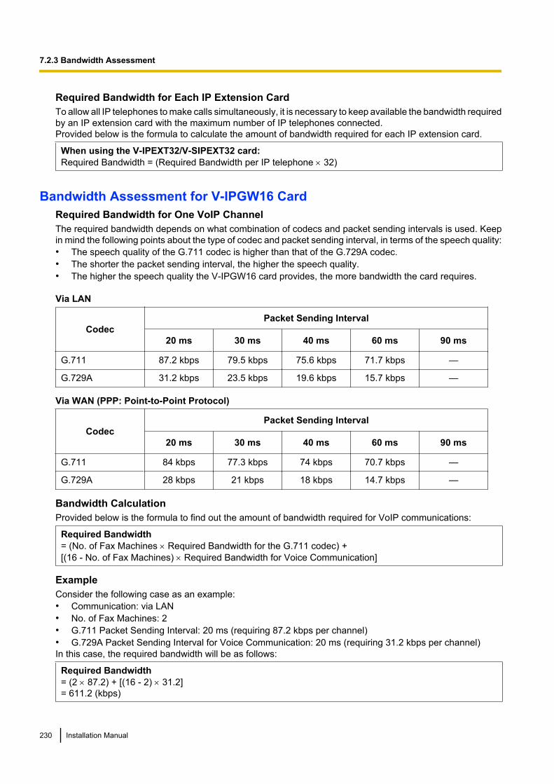
Required Bandwidth for Each IP Extension CardTo allow all IP telephones to make calls simultaneously, it is necessary to keep available the bandwidth requiredby an IP extension card with the maximum number of IP telephones connected.Provided below is the formula to calculate the amount of bandwidth required for each IP extension card.
When using the V-IPEXT32/V-SIPEXT32 card:Required Bandwidth = (Required Bandwidth per IP telephone ´ 32)
Bandwidth Assessment for V-IPGW16 CardRequired Bandwidth for One VoIP ChannelThe required bandwidth depends on what combination of codecs and packet sending intervals is used. Keepin mind the following points about the type of codec and packet sending interval, in terms of the speech quality:• The speech quality of the G.711 codec is higher than that of the G.729A codec.• The shorter the packet sending interval, the higher the speech quality.• The higher the speech quality the V-IPGW16 card provides, the more bandwidth the card requires.
Via LAN
CodecPacket Sending Interval
20 ms 30 ms 40 ms 60 ms 90 ms
G.711 87.2 kbps 79.5 kbps 75.6 kbps 71.7 kbps —
G.729A 31.2 kbps 23.5 kbps 19.6 kbps 15.7 kbps —
Via WAN (PPP: Point-to-Point Protocol)
CodecPacket Sending Interval
20 ms 30 ms 40 ms 60 ms 90 ms
G.711 84 kbps 77.3 kbps 74 kbps 70.7 kbps —
G.729A 28 kbps 21 kbps 18 kbps 14.7 kbps —
Bandwidth CalculationProvided below is the formula to find out the amount of bandwidth required for VoIP communications:
Required Bandwidth= (No. of Fax Machines ´ Required Bandwidth for the G.711 codec) +[(16 - No. of Fax Machines) ´ Required Bandwidth for Voice Communication]
ExampleConsider the following case as an example:• Communication: via LAN• No. of Fax Machines: 2• G.711 Packet Sending Interval: 20 ms (requiring 87.2 kbps per channel)• G.729A Packet Sending Interval for Voice Communication: 20 ms (requiring 31.2 kbps per channel)In this case, the required bandwidth will be as follows:
Required Bandwidth= (2 ´ 87.2) + [(16 - 2) ´ 31.2]= 611.2 (kbps)
230 Installation Manual
7.2.3 Bandwidth Assessment
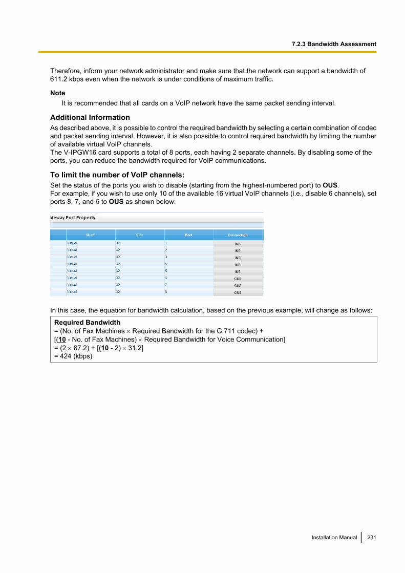
Therefore, inform your network administrator and make sure that the network can support a bandwidth of611.2 kbps even when the network is under conditions of maximum traffic.
NoteIt is recommended that all cards on a VoIP network have the same packet sending interval.
Additional InformationAs described above, it is possible to control the required bandwidth by selecting a certain combination of codecand packet sending interval. However, it is also possible to control required bandwidth by limiting the numberof available virtual VoIP channels.The V-IPGW16 card supports a total of 8 ports, each having 2 separate channels. By disabling some of theports, you can reduce the bandwidth required for VoIP communications.
To limit the number of VoIP channels:Set the status of the ports you wish to disable (starting from the highest-numbered port) to OUS.For example, if you wish to use only 10 of the available 16 virtual VoIP channels (i.e., disable 6 channels), setports 8, 7, and 6 to OUS as shown below:
In this case, the equation for bandwidth calculation, based on the previous example, will change as follows:
Required Bandwidth= (No. of Fax Machines ´ Required Bandwidth for the G.711 codec) +[(10 - No. of Fax Machines) ´ Required Bandwidth for Voice Communication]= (2 ´ 87.2) + [(10 - 2) ´ 31.2]= 424 (kbps)
Installation Manual 231
7.2.3 Bandwidth Assessment
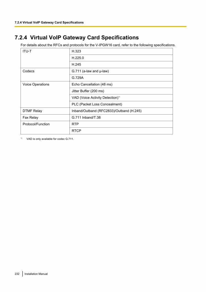
7.2.4 Virtual VoIP Gateway Card SpecificationsFor details about the RFCs and protocols for the V-IPGW16 card, refer to the following specifications.
ITU-T H.323
H.225.0
H.245
Codecs G.711 (a-law and µ-law)
G.729A
Voice Operations Echo Cancellation (48 ms)
Jitter Buffer (200 ms)
VAD (Voice Activity Detection)*1
PLC (Packet Loss Concealment)
DTMF Relay Inband/Outband (RFC2833)/Outband (H.245)
Fax Relay G.711 Inband/T.38
Protocol/Function RTP
RTCP
*1 VAD is only available for codec G.711.
232 Installation Manual
7.2.4 Virtual VoIP Gateway Card Specifications
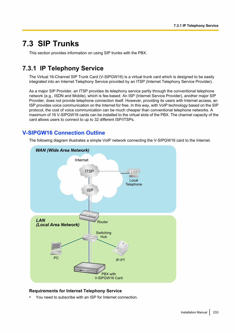
7.3 SIP TrunksThis section provides information on using SIP trunks with the PBX.
7.3.1 IP Telephony ServiceThe Virtual 16-Channel SIP Trunk Card (V-SIPGW16) is a virtual trunk card which is designed to be easilyintegrated into an Internet Telephony Service provided by an ITSP (Internet Telephony Service Provider).
As a major SIP Provider, an ITSP provides its telephony service partly through the conventional telephonenetwork (e.g., ISDN and Mobile), which is fee-based. An ISP (Internet Service Provider), another major SIPProvider, does not provide telephone connection itself. However, providing its users with Internet access, anISP provides voice communication on the Internet for free. In this way, with VoIP technology based on the SIPprotocol, the cost of voice communication can be much cheaper than conventional telephone networks. Amaximum of 16 V-SIPGW16 cards can be installed to the virtual slots of the PBX. The channel capacity of thecard allows users to connect to up to 32 different ISP/ITSPs.
V-SIPGW16 Connection OutlineThe following diagram illustrates a simple VoIP network connecting the V-SIPGW16 card to the Internet.
PBX withV-SIPGW16 Card
PC
LAN
(Local Area Network)
WAN (Wide Area Network)
Internet
LocalTelephone
IP-PT
ISP
ITSP
Router
SwitchingHub
Requirements for Internet Telephony Service• You need to subscribe with an ISP for Internet connection.
Installation Manual 233
7.3.1 IP Telephony Service
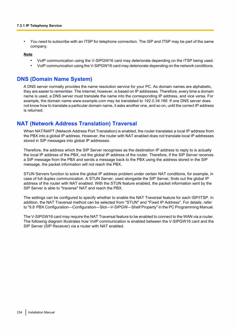
• You need to subscribe with an ITSP for telephone connection. The ISP and ITSP may be part of the samecompany.
Note• VoIP communication using the V-SIPGW16 card may deteriorate depending on the ITSP being used.• VoIP communication using the V-SIPGW16 card may deteriorate depending on the network conditions.
DNS (Domain Name System)A DNS server normally provides the name resolution service for your PC. As domain names are alphabetic,they are easier to remember. The Internet, however, is based on IP addresses. Therefore, every time a domainname is used, a DNS server must translate the name into the corresponding IP address, and vice versa. Forexample, the domain name www.example.com may be translated to 192.0.34.166. If one DNS server doesnot know how to translate a particular domain name, it asks another one, and so on, until the correct IP addressis returned.
NAT (Network Address Translation) TraversalWhen NAT/NAPT (Network Address Port Translation) is enabled, the router translates a local IP address fromthe PBX into a global IP address. However, the router with NAT enabled does not translate local IP addressesstored in SIP messages into global IP addresses.
Therefore, the address which the SIP Server recognises as the destination IP address to reply to is actuallythe local IP address of the PBX, not the global IP address of the router. Therefore, if the SIP Server receivesa SIP message from the PBX and sends a message back to the PBX using the address stored in the SIPmessage, the packet information will not reach the PBX.
STUN Servers function to solve the global IP address problem under certain NAT conditions, for example, incase of full duplex communication. A STUN Server, used alongside the SIP Server, finds out the global IPaddress of the router with NAT enabled. With the STUN feature enabled, the packet information sent by theSIP Server is able to "traverse" NAT and reach the PBX.
The settings can be configured to specify whether to enable the NAT Traversal feature for each ISP/ITSP. Inaddition, the NAT Traversal method can be selected from "STUN" and "Fixed IP Address". For details, referto "9.8 PBX Configuration—Configuration—Slot—V-SIPGW—Shelf Property" in the PC Programming Manual.
The V-SIPGW16 card may require the NAT Traversal feature to be enabled to connect to the WAN via a router.The following diagram illustrates how VoIP communication is enabled between the V-SIPGW16 card and theSIP Server (SIP Receiver) via a router with NAT enabled.
234 Installation Manual
7.3.1 IP Telephony Service
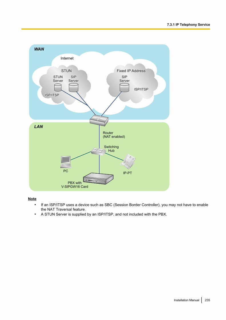
LAN
WAN
Internet
STUNSTUN
STUNSTUNServerServer
SIPSIPServerServer
Fixed IP AddressFixed IP Address
SIPSIPServerServer
STUN
STUNServer
SIPServer
Fixed IP Address
SIPServer
PBX withV-SIPGW16 Card
ISP/ITSPISP/ITSP
ISP/ITSPISP/ITSP
ISP/ITSP
ISP/ITSP
Router(NAT enabled)
PCIP-PT
SwitchingHub
Note• If an ISP/ITSP uses a device such as SBC (Session Border Controller), you may not have to enable
the NAT Traversal feature.• A STUN Server is supplied by an ISP/ITSP, and not included with the PBX.
Installation Manual 235
7.3.1 IP Telephony Service
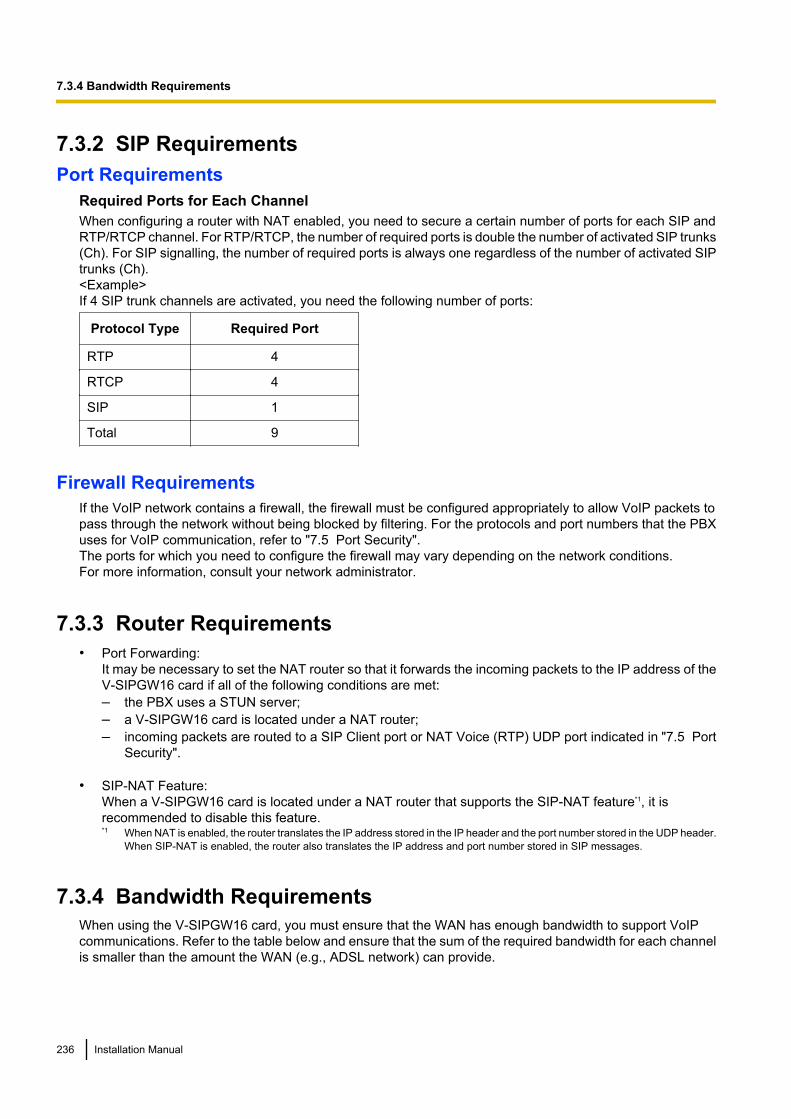
7.3.2 SIP RequirementsPort Requirements
Required Ports for Each ChannelWhen configuring a router with NAT enabled, you need to secure a certain number of ports for each SIP andRTP/RTCP channel. For RTP/RTCP, the number of required ports is double the number of activated SIP trunks(Ch). For SIP signalling, the number of required ports is always one regardless of the number of activated SIPtrunks (Ch).<Example>If 4 SIP trunk channels are activated, you need the following number of ports:
Protocol Type Required Port
RTP 4
RTCP 4
SIP 1
Total 9
Firewall RequirementsIf the VoIP network contains a firewall, the firewall must be configured appropriately to allow VoIP packets topass through the network without being blocked by filtering. For the protocols and port numbers that the PBXuses for VoIP communication, refer to "7.5 Port Security".The ports for which you need to configure the firewall may vary depending on the network conditions.For more information, consult your network administrator.
7.3.3 Router Requirements• Port Forwarding:
It may be necessary to set the NAT router so that it forwards the incoming packets to the IP address of theV-SIPGW16 card if all of the following conditions are met:– the PBX uses a STUN server;– a V-SIPGW16 card is located under a NAT router;– incoming packets are routed to a SIP Client port or NAT Voice (RTP) UDP port indicated in "7.5 Port
Security".
• SIP-NAT Feature:When a V-SIPGW16 card is located under a NAT router that supports the SIP-NAT feature*1, it isrecommended to disable this feature.*1 When NAT is enabled, the router translates the IP address stored in the IP header and the port number stored in the UDP header.
When SIP-NAT is enabled, the router also translates the IP address and port number stored in SIP messages.
7.3.4 Bandwidth RequirementsWhen using the V-SIPGW16 card, you must ensure that the WAN has enough bandwidth to support VoIPcommunications. Refer to the table below and ensure that the sum of the required bandwidth for each channelis smaller than the amount the WAN (e.g., ADSL network) can provide.
236 Installation Manual
7.3.4 Bandwidth Requirements
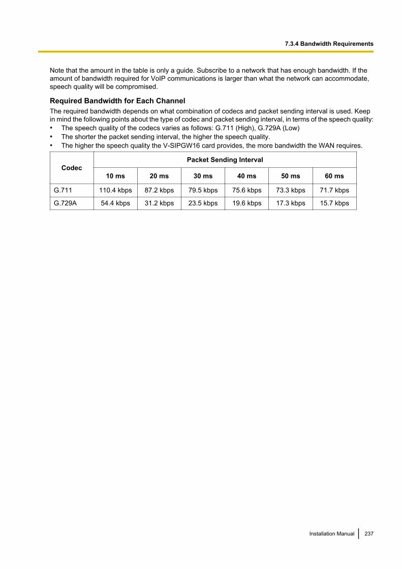
Note that the amount in the table is only a guide. Subscribe to a network that has enough bandwidth. If theamount of bandwidth required for VoIP communications is larger than what the network can accommodate,speech quality will be compromised.
Required Bandwidth for Each ChannelThe required bandwidth depends on what combination of codecs and packet sending interval is used. Keepin mind the following points about the type of codec and packet sending interval, in terms of the speech quality:• The speech quality of the codecs varies as follows: G.711 (High), G.729A (Low)• The shorter the packet sending interval, the higher the speech quality.• The higher the speech quality the V-SIPGW16 card provides, the more bandwidth the WAN requires.
CodecPacket Sending Interval
10 ms 20 ms 30 ms 40 ms 50 ms 60 ms
G.711 110.4 kbps 87.2 kbps 79.5 kbps 75.6 kbps 73.3 kbps 71.7 kbps
G.729A 54.4 kbps 31.2 kbps 23.5 kbps 19.6 kbps 17.3 kbps 15.7 kbps
Installation Manual 237
7.3.4 Bandwidth Requirements
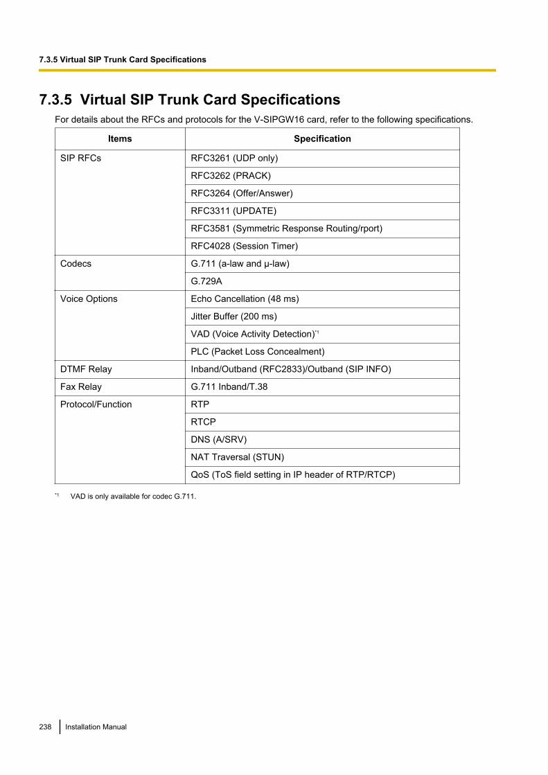
7.3.5 Virtual SIP Trunk Card SpecificationsFor details about the RFCs and protocols for the V-SIPGW16 card, refer to the following specifications.
Items Specification
SIP RFCs RFC3261 (UDP only)
RFC3262 (PRACK)
RFC3264 (Offer/Answer)
RFC3311 (UPDATE)
RFC3581 (Symmetric Response Routing/rport)
RFC4028 (Session Timer)
Codecs G.711 (a-law and µ-law)
G.729A
Voice Options Echo Cancellation (48 ms)
Jitter Buffer (200 ms)
VAD (Voice Activity Detection)*1
PLC (Packet Loss Concealment)
DTMF Relay Inband/Outband (RFC2833)/Outband (SIP INFO)
Fax Relay G.711 Inband/T.38
Protocol/Function RTP
RTCP
DNS (A/SRV)
NAT Traversal (STUN)
QoS (ToS field setting in IP header of RTP/RTCP)
*1 VAD is only available for codec G.711.
238 Installation Manual
7.3.5 Virtual SIP Trunk Card Specifications
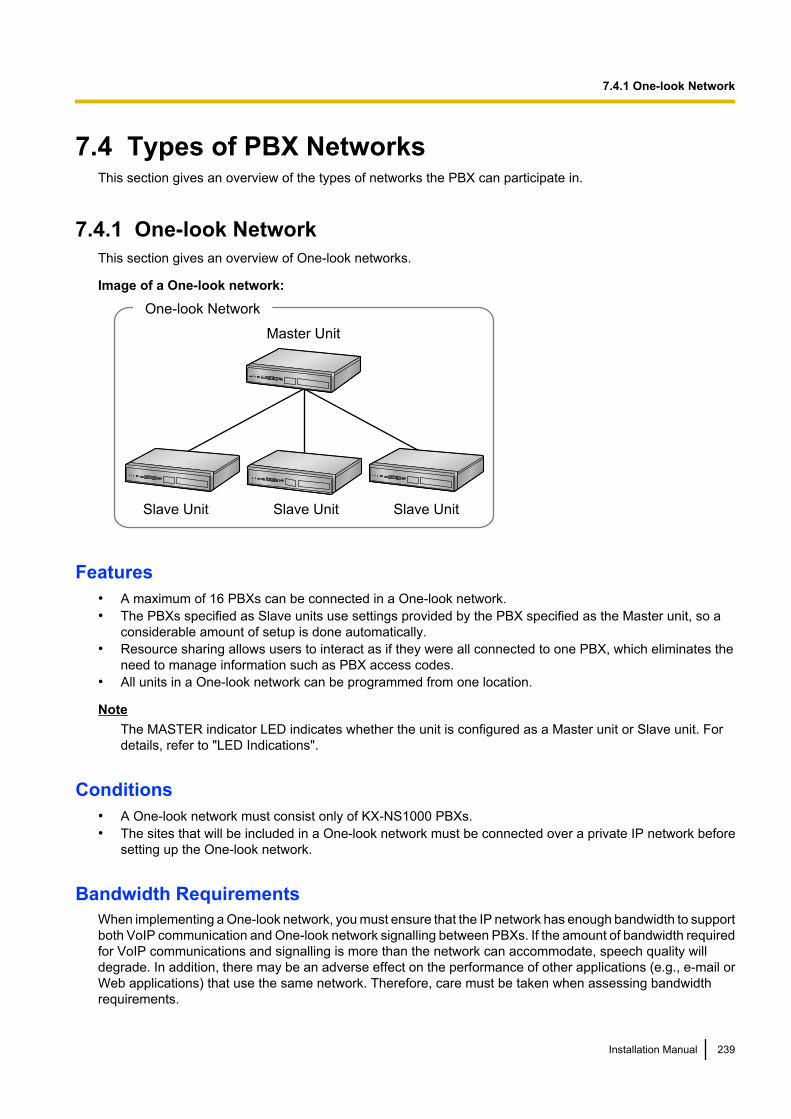
7.4 Types of PBX NetworksThis section gives an overview of the types of networks the PBX can participate in.
7.4.1 One-look NetworkThis section gives an overview of One-look networks.
Image of a One-look network:
Master Unit
Slave Unit Slave Unit Slave Unit
One-look Network
Features• A maximum of 16 PBXs can be connected in a One-look network.• The PBXs specified as Slave units use settings provided by the PBX specified as the Master unit, so a
considerable amount of setup is done automatically.• Resource sharing allows users to interact as if they were all connected to one PBX, which eliminates the
need to manage information such as PBX access codes.• All units in a One-look network can be programmed from one location.
NoteThe MASTER indicator LED indicates whether the unit is configured as a Master unit or Slave unit. Fordetails, refer to "LED Indications".
Conditions• A One-look network must consist only of KX-NS1000 PBXs.• The sites that will be included in a One-look network must be connected over a private IP network before
setting up the One-look network.
Bandwidth RequirementsWhen implementing a One-look network, you must ensure that the IP network has enough bandwidth to supportboth VoIP communication and One-look network signalling between PBXs. If the amount of bandwidth requiredfor VoIP communications and signalling is more than the network can accommodate, speech quality willdegrade. In addition, there may be an adverse effect on the performance of other applications (e.g., e-mail orWeb applications) that use the same network. Therefore, care must be taken when assessing bandwidthrequirements.
Installation Manual 239
7.4.1 One-look Network
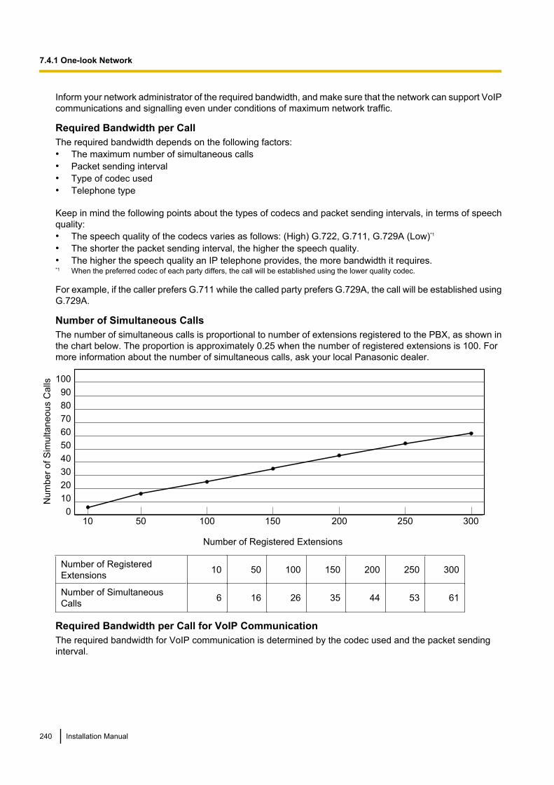
Inform your network administrator of the required bandwidth, and make sure that the network can support VoIPcommunications and signalling even under conditions of maximum network traffic.
Required Bandwidth per CallThe required bandwidth depends on the following factors:• The maximum number of simultaneous calls• Packet sending interval• Type of codec used• Telephone type
Keep in mind the following points about the types of codecs and packet sending intervals, in terms of speechquality:• The speech quality of the codecs varies as follows: (High) G.722, G.711, G.729A (Low)*1
• The shorter the packet sending interval, the higher the speech quality.• The higher the speech quality an IP telephone provides, the more bandwidth it requires.*1 When the preferred codec of each party differs, the call will be established using the lower quality codec.
For example, if the caller prefers G.711 while the called party prefers G.729A, the call will be established usingG.729A.
Number of Simultaneous CallsThe number of simultaneous calls is proportional to number of extensions registered to the PBX, as shown inthe chart below. The proportion is approximately 0.25 when the number of registered extensions is 100. Formore information about the number of simultaneous calls, ask your local Panasonic dealer.
0
10
20
30
40
50
60
70
80
90
100
30020010010 50 150 250
Num
ber
of S
imultaneous C
alls
Number of Registered Extensions
Number of RegisteredExtensions 10 50 100 150 200 250 300
Number of SimultaneousCalls 6 16 26 35 44 53 61
Required Bandwidth per Call for VoIP CommunicationThe required bandwidth for VoIP communication is determined by the codec used and the packet sendinginterval.
240 Installation Manual
7.4.1 One-look Network
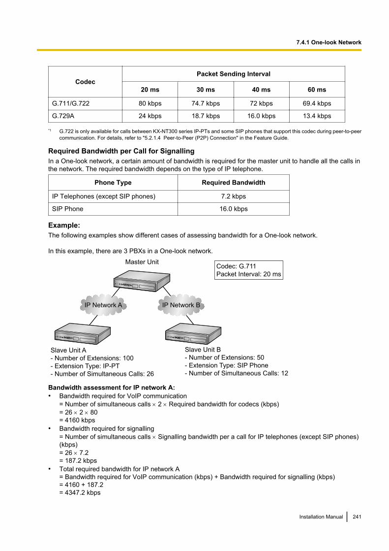
CodecPacket Sending Interval
20 ms 30 ms 40 ms 60 ms
G.711/G.722 80 kbps 74.7 kbps 72 kbps 69.4 kbps
G.729A 24 kbps 18.7 kbps 16.0 kbps 13.4 kbps
*1 G.722 is only available for calls between KX-NT300 series IP-PTs and some SIP phones that support this codec during peer-to-peercommunication. For details, refer to "5.2.1.4 Peer-to-Peer (P2P) Connection" in the Feature Guide.
Required Bandwidth per Call for SignallingIn a One-look network, a certain amount of bandwidth is required for the master unit to handle all the calls inthe network. The required bandwidth depends on the type of IP telephone.
Phone Type Required Bandwidth
IP Telephones (except SIP phones) 7.2 kbps
SIP Phone 16.0 kbps
Example:The following examples show different cases of assessing bandwidth for a One-look network.
In this example, there are 3 PBXs in a One-look network.
Master Unit
Slave Unit A
- Number of Extensions: 100
- Extension Type: IP-PT
- Number of Simultaneous Calls: 26
Slave Unit B
- Number of Extensions: 50
- Extension Type: SIP Phone
- Number of Simultaneous Calls: 12
IP Network BIP Network A
Codec: G.711
Packet Interval: 20 ms
Bandwidth assessment for IP network A:• Bandwidth required for VoIP communication
= Number of simultaneous calls ´ 2 ´ Required bandwidth for codecs (kbps)= 26 ´ 2 ´ 80= 4160 kbps
• Bandwidth required for signalling= Number of simultaneous calls ´ Signalling bandwidth per a call for IP telephones (except SIP phones)(kbps)= 26 ´ 7.2= 187.2 kbps
• Total required bandwidth for IP network A= Bandwidth required for VoIP communication (kbps) + Bandwidth required for signalling (kbps)= 4160 + 187.2= 4347.2 kbps
Installation Manual 241
7.4.1 One-look Network
Bandwidth assessment for IP network B:• Bandwidth required for VoIP communication
= Number of simultaneous calls ´ 2 ´ Required bandwidth for codecs (kbps)= 12 ´ 2 ´ 80= 1920 kbps
• Bandwidth required for signallingNumber of simultaneous calls ´ Signalling bandwidth per a call for SIP phones (kbps)= 12 ´ 16= 192 kbps
• Total required bandwidth for IP network B= Bandwidth required for VoIP communication (kbps) + Bandwidth required for signalling (kbps)= 1920 + 192= 2112 kbps
Required Items• KX-NSN001: Activation Key for One-look Network (One-look Network)
Networking Notes• When setting up a PBX using Easy Setup Wizard, you specify whether the PBX will be the Master unit or
a Slave unit. For more details, refer to "5.4.1 Easy Setup Wizard".• You can add Slave units to the One-look network using Web Maintenance Console. For more details, refer
to "5.5 Programming a One-look Network".
Note• For more details about One-look networks, refer to "4.2 One-look Networking" in the Feature Guide.• For details about configuring and programming a One-look networks, refer to "3.1.1 Home Screen—
Add Site Wizard" in the PC Programming Manual.
242 Installation Manual
7.4.1 One-look Network
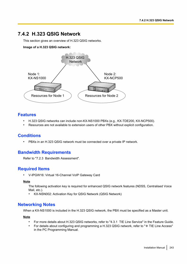
7.4.2 H.323 QSIG NetworkThis section gives an overview of H.323 QSIG networks.
Image of a H.323 QSIG network:
Resources for Node 1
Node 1:
KX-NS1000
Resources for Node 2
Node 2:
KX-NCP500
H.323 QSIG
Network
Features• H.323 QSIG networks can include non-KX-NS1000 PBXs (e.g., KX-TDE200, KX-NCP500).• Resources are not available to extension users of other PBX without explicit configuration.
Conditions• PBXs in an H.323 QSIG network must be connected over a private IP network.
Bandwidth RequirementsRefer to "7.2.3 Bandwidth Assessment".
Required Items• V-IPGW16: Virtual 16-Channel VoIP Gateway Card
NoteThe following activation key is required for enhanced QSIG network features (NDSS, Centralised VoiceMail, etc.).• KX-NSN002: Activation Key for QSIG Network (QSIG Network)
Networking NotesWhen a KX-NS1000 is included in the H.323 QSIG network, the PBX must be specified as a Master unit.
Note• For more details about H.323 QSIG networks, refer to "4.3.1 TIE Line Service" in the Feature Guide.• For details about configuring and programming a H.323 QSIG network, refer to " TIE Line Access"
in the PC Programming Manual.
Installation Manual 243
7.4.2 H.323 QSIG Network
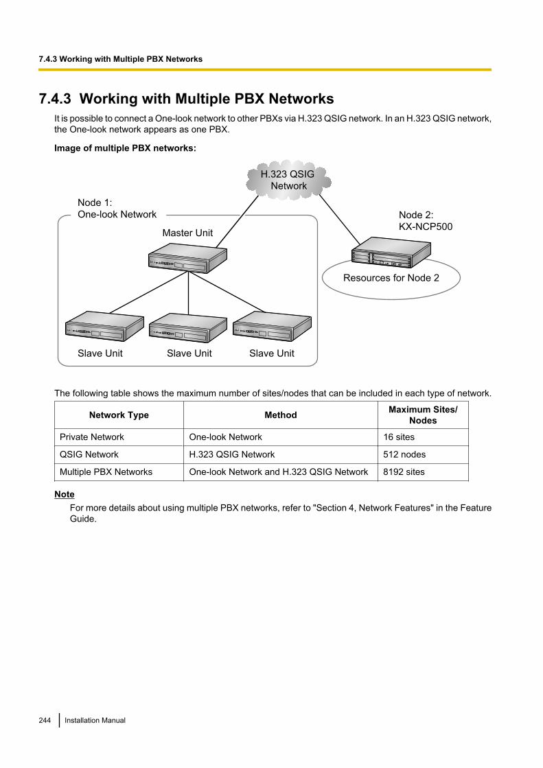
7.4.3 Working with Multiple PBX NetworksIt is possible to connect a One-look network to other PBXs via H.323 QSIG network. In an H.323 QSIG network,the One-look network appears as one PBX.
Image of multiple PBX networks:
H.323 QSIG Network
Master Unit
Slave Unit Slave Unit Slave Unit
Node 1:One-look Network
Resources for Node 2
Node 2:KX-NCP500
The following table shows the maximum number of sites/nodes that can be included in each type of network.
Network Type Method Maximum Sites/Nodes
Private Network One-look Network 16 sites
QSIG Network H.323 QSIG Network 512 nodes
Multiple PBX Networks One-look Network and H.323 QSIG Network 8192 sites
NoteFor more details about using multiple PBX networks, refer to "Section 4, Network Features" in the FeatureGuide.
244 Installation Manual
7.4.3 Working with Multiple PBX Networks
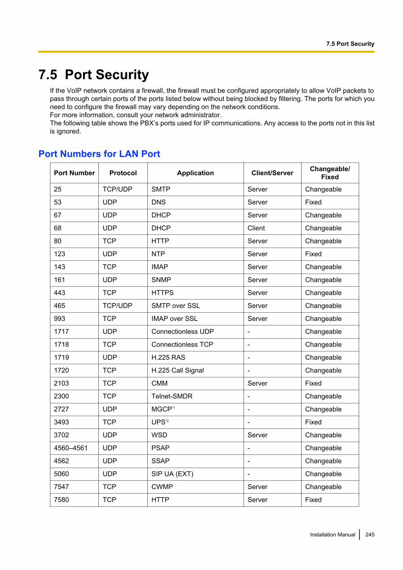
7.5 Port SecurityIf the VoIP network contains a firewall, the firewall must be configured appropriately to allow VoIP packets topass through certain ports of the ports listed below without being blocked by filtering. The ports for which youneed to configure the firewall may vary depending on the network conditions.For more information, consult your network administrator.The following table shows the PBX’s ports used for IP communications. Any access to the ports not in this listis ignored.
Port Numbers for LAN Port
Port Number Protocol Application Client/Server Changeable/Fixed
25 TCP/UDP SMTP Server Changeable
53 UDP DNS Server Fixed
67 UDP DHCP Server Changeable
68 UDP DHCP Client Changeable
80 TCP HTTP Server Changeable
123 UDP NTP Server Fixed
143 TCP IMAP Server Changeable
161 UDP SNMP Server Changeable
443 TCP HTTPS Server Changeable
465 TCP/UDP SMTP over SSL Server Changeable
993 TCP IMAP over SSL Server Changeable
1717 UDP Connectionless UDP - Changeable
1718 TCP Connectionless TCP - Changeable
1719 UDP H.225 RAS - Changeable
1720 TCP H.225 Call Signal - Changeable
2103 TCP CMM Server Fixed
2300 TCP Telnet-SMDR - Changeable
2727 UDP MGCP*1 - Changeable
3493 TCP UPS*2 - Fixed
3702 UDP WSD Server Changeable
4560–4561 UDP PSAP - Changeable
4562 UDP SSAP - Changeable
5060 UDP SIP UA (EXT) - Changeable
7547 TCP CWMP Server Changeable
7580 TCP HTTP Server Fixed
Installation Manual 245
7.5 Port Security
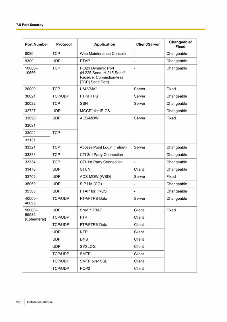
Port Number Protocol Application Client/Server Changeable/Fixed
8080 TCP Web Maintenance Console - Changeable
9300 UDP PTAP - Changeable
10000–10655
TCP H.323 Dynamic Port(H.225 Send, H.245 Send/Receive, Connection-less[TCP] Send Port)
- Changeable
20000 TCP UM-VMA*3 Server Fixed
30021 TCP/UDP FTP/FTPS Server Changeable
30022 TCP SSH Server Changeable
32727 UDP MGCP*1 for IP-CS - Changeable
33090 UDP ACS-MDW Server Fixed
33091
33092 TCP
33131
33321 TCP Access Point Login (Telnet) Server Changeable
33333 TCP CTI 3rd Party Connection - Changeable
33334 TCP CTI 1st Party Connection - Changeable
33478 UDP STUN Client Changeable
33702 UDP ACS-MDW (WSD) Server Fixed
35060 UDP SIP UA (CO) - Changeable
39300 UDP PTAP for IP-CS - Changeable
40000–40095
TCP/UDP FTP/FTPS-Data Server Changeable
50000–65535(Ephemeral)
UDP SNMP TRAP Client Fixed
TCP/UDP FTP Client
TCP/UDP FTP/FTPS-Data Client
UDP NTP Client
UDP DNS Client
UDP SYSLOG Client
TCP/UDP SMTP Client
TCP/UDP SMTP over SSL Client
TCP/UDP POP3 Client
246 Installation Manual
7.5 Port Security
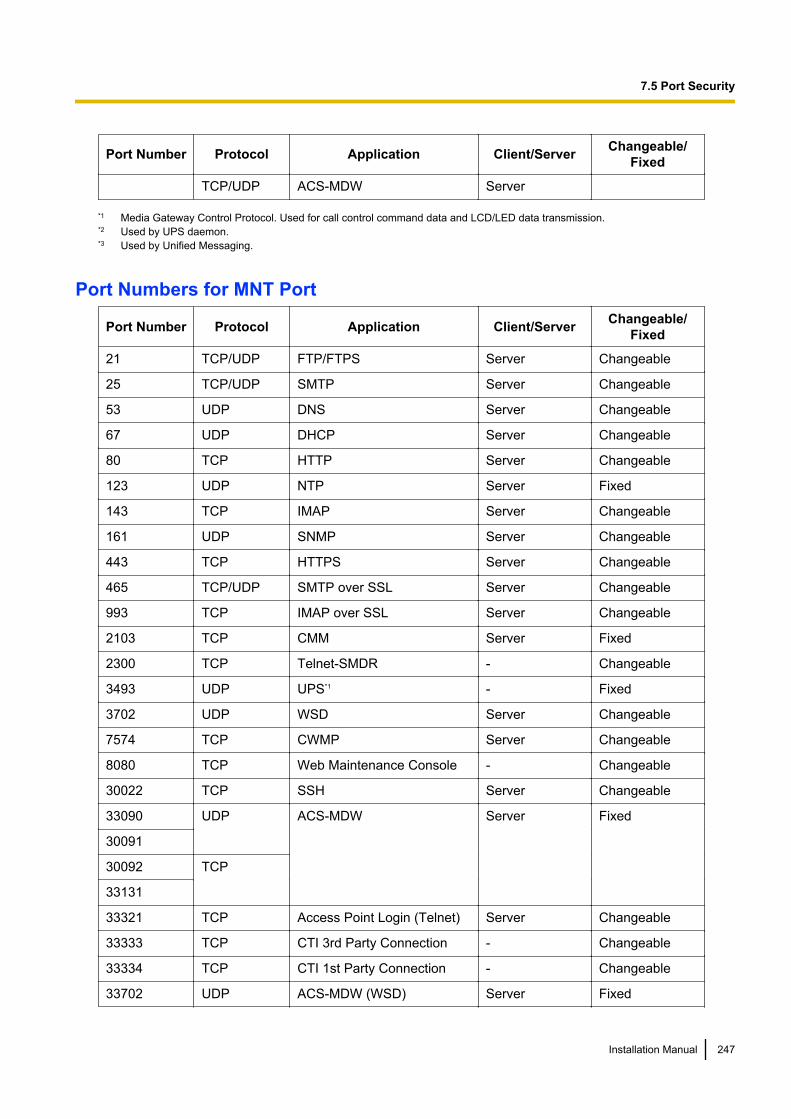
Port Number Protocol Application Client/Server Changeable/Fixed
TCP/UDP ACS-MDW Server
*1 Media Gateway Control Protocol. Used for call control command data and LCD/LED data transmission.*2 Used by UPS daemon.*3 Used by Unified Messaging.
Port Numbers for MNT Port
Port Number Protocol Application Client/Server Changeable/Fixed
21 TCP/UDP FTP/FTPS Server Changeable
25 TCP/UDP SMTP Server Changeable
53 UDP DNS Server Changeable
67 UDP DHCP Server Changeable
80 TCP HTTP Server Changeable
123 UDP NTP Server Fixed
143 TCP IMAP Server Changeable
161 UDP SNMP Server Changeable
443 TCP HTTPS Server Changeable
465 TCP/UDP SMTP over SSL Server Changeable
993 TCP IMAP over SSL Server Changeable
2103 TCP CMM Server Fixed
2300 TCP Telnet-SMDR - Changeable
3493 UDP UPS*1 - Fixed
3702 UDP WSD Server Changeable
7574 TCP CWMP Server Changeable
8080 TCP Web Maintenance Console - Changeable
30022 TCP SSH Server Changeable
33090 UDP ACS-MDW Server Fixed
30091
30092 TCP
33131
33321 TCP Access Point Login (Telnet) Server Changeable
33333 TCP CTI 3rd Party Connection - Changeable
33334 TCP CTI 1st Party Connection - Changeable
33702 UDP ACS-MDW (WSD) Server Fixed
Installation Manual 247
7.5 Port Security
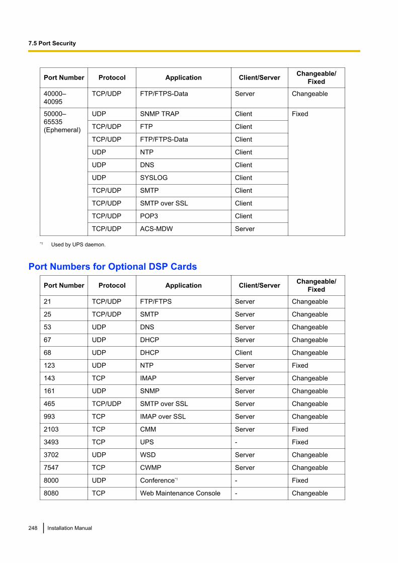
Port Number Protocol Application Client/Server Changeable/Fixed
40000–40095
TCP/UDP FTP/FTPS-Data Server Changeable
50000–65535(Ephemeral)
UDP SNMP TRAP Client Fixed
TCP/UDP FTP Client
TCP/UDP FTP/FTPS-Data Client
UDP NTP Client
UDP DNS Client
UDP SYSLOG Client
TCP/UDP SMTP Client
TCP/UDP SMTP over SSL Client
TCP/UDP POP3 Client
TCP/UDP ACS-MDW Server
*1 Used by UPS daemon.
Port Numbers for Optional DSP Cards
Port Number Protocol Application Client/Server Changeable/Fixed
21 TCP/UDP FTP/FTPS Server Changeable
25 TCP/UDP SMTP Server Changeable
53 UDP DNS Server Changeable
67 UDP DHCP Server Changeable
68 UDP DHCP Client Changeable
123 UDP NTP Server Fixed
143 TCP IMAP Server Changeable
161 UDP SNMP Server Changeable
465 TCP/UDP SMTP over SSL Server Changeable
993 TCP IMAP over SSL Server Changeable
2103 TCP CMM Server Fixed
3493 TCP UPS - Fixed
3702 UDP WSD Server Changeable
7547 TCP CWMP Server Changeable
8000 UDP Conference*1 - Fixed
8080 TCP Web Maintenance Console - Changeable
248 Installation Manual
7.5 Port Security
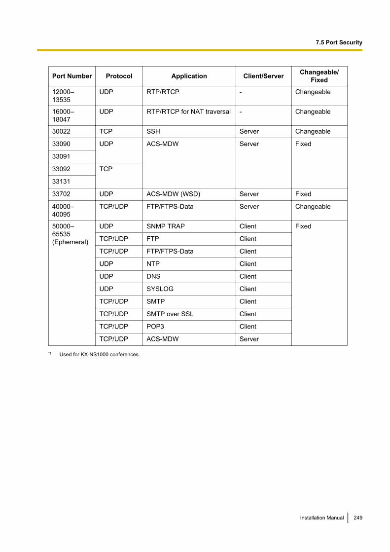
Port Number Protocol Application Client/Server Changeable/Fixed
12000–13535
UDP RTP/RTCP - Changeable
16000–18047
UDP RTP/RTCP for NAT traversal - Changeable
30022 TCP SSH Server Changeable
33090 UDP ACS-MDW Server Fixed
33091
33092 TCP
33131
33702 UDP ACS-MDW (WSD) Server Fixed
40000–40095
TCP/UDP FTP/FTPS-Data Server Changeable
50000–65535(Ephemeral)
UDP SNMP TRAP Client Fixed
TCP/UDP FTP Client
TCP/UDP FTP/FTPS-Data Client
UDP NTP Client
UDP DNS Client
UDP SYSLOG Client
TCP/UDP SMTP Client
TCP/UDP SMTP over SSL Client
TCP/UDP POP3 Client
TCP/UDP ACS-MDW Server
*1 Used for KX-NS1000 conferences.
Installation Manual 249
7.5 Port Security
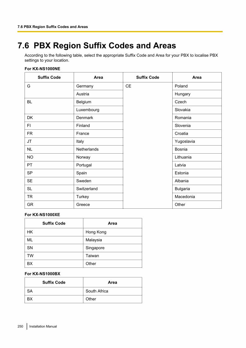
7.6 PBX Region Suffix Codes and AreasAccording to the following table, select the appropriate Suffix Code and Area for your PBX to localise PBXsettings to your location.
For KX-NS1000NE
Suffix Code Area Suffix Code Area
G Germany CE Poland
Austria Hungary
BL Belgium Czech
Luxembourg Slovakia
DK Denmark Romania
FI Finland Slovenia
FR France Croatia
JT Italy Yugoslavia
NL Netherlands Bosnia
NO Norway Lithuania
PT Portugal Latvia
SP Spain Estonia
SE Sweden Albania
SL Switzerland Bulgaria
TR Turkey Macedonia
GR Greece Other
For KX-NS1000XE
Suffix Code Area
HK Hong Kong
ML Malaysia
SN Singapore
TW Taiwan
BX Other
For KX-NS1000BX
Suffix Code Area
SA South Africa
BX Other
250 Installation Manual
7.6 PBX Region Suffix Codes and Areas

For KX-NS1000AL
Suffix Code Area
AL Australia
NZ New Zealand
Installation Manual 251
7.6 PBX Region Suffix Codes and Areas
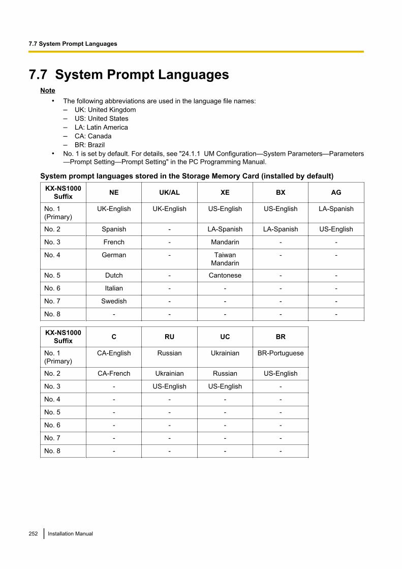
7.7 System Prompt LanguagesNote
• The following abbreviations are used in the language file names:– UK: United Kingdom– US: United States– LA: Latin America– CA: Canada– BR: Brazil
• No. 1 is set by default. For details, see "24.1.1 UM Configuration—System Parameters—Parameters—Prompt Setting—Prompt Setting" in the PC Programming Manual.
System prompt languages stored in the Storage Memory Card (installed by default)KX-NS1000
Suffix NE UK/AL XE BX AG
No. 1(Primary)
UK-English UK-English US-English US-English LA-Spanish
No. 2 Spanish - LA-Spanish LA-Spanish US-English
No. 3 French - Mandarin - -
No. 4 German - TaiwanMandarin
- -
No. 5 Dutch - Cantonese - -
No. 6 Italian - - - -
No. 7 Swedish - - - -
No. 8 - - - - -
KX-NS1000Suffix C RU UC BR
No. 1(Primary)
CA-English Russian Ukrainian BR-Portuguese
No. 2 CA-French Ukrainian Russian US-English
No. 3 - US-English US-English -
No. 4 - - - -
No. 5 - - - -
No. 6 - - - -
No. 7 - - - -
No. 8 - - - -
252 Installation Manual
7.7 System Prompt Languages
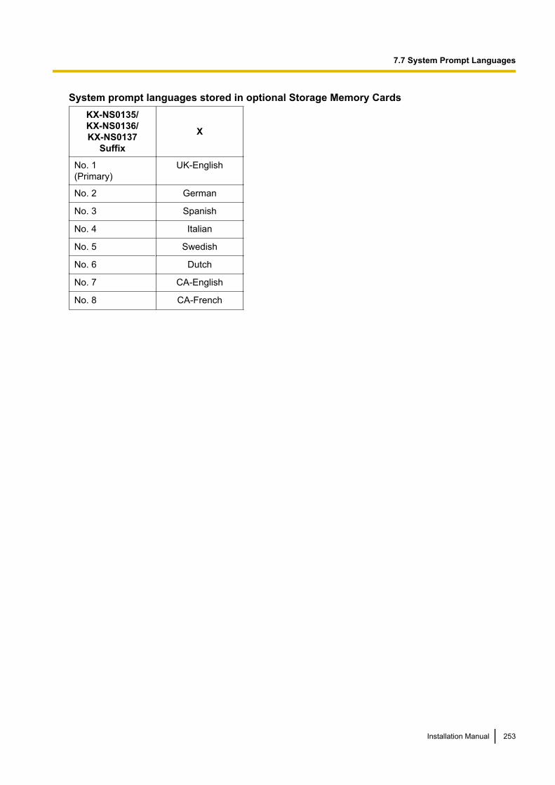
System prompt languages stored in optional Storage Memory CardsKX-NS0135/KX-NS0136/KX-NS0137
Suffix
X
No. 1(Primary)
UK-English
No. 2 German
No. 3 Spanish
No. 4 Italian
No. 5 Swedish
No. 6 Dutch
No. 7 CA-English
No. 8 CA-French
Installation Manual 253
7.7 System Prompt Languages

254 Installation Manual
7.7 System Prompt Languages

Index
Installation Manual 255
Numerics19-inch Rack Mounting 852-Port Analogue Trunk / 2-Port SLT Card(KX-NS0180) 28, 1044-Port BRI / 2-Port SLT Card (KX-NS0280) 28, 106
AAccessing Port Properties 160Activation Key Code 56Activation Key, Cellular Phone Extension 49Activation Key, Communication Assistant (CA) User 50Activation Key, IP Telephone 44Activation Key, IP Telephone Capacity 43Activation Key, IP Trunks 42Activation Key, Networking 46Activation Key, Unified Messaging System (Features) 46Activation Key, Unified Messaging System (Mailbox) 48Activation Key, Unified Messaging System (Two-wayRecording/Two-way Transfer Users) 49Activation Key, Unified Messaging System (UnifiedMessaging Ports) 47Address Translation Table 154Assigning the Hunt Pattern 153
BBGM 123
CCable Distance 118Characteristics 31Connection Chart for LAN Connection 127Connection Diagram, System 26Connector Types 83CTI Server Connection (via LAN Port) 127CTI—Third Party Call Control 127
DDHCP server feature 219Diffserv (Differentiated Services) 183DNS (Domain Name System) 234DNS Server 234Door Opener 116, 119Doorphone 116, 119Doorphone Interface Card (KX-NS0161) 28, 116
EError Log 213Extension Number Method 157External Sensor 117, 119
FFAX Interface Card (KX-NS0106) 28, 101Ferrite Core 84Fixed IP Address 234Frame Earth Connection 65
GGatekeeper 229
IInformation about the Virtual Cards 102Installation Precautions 58Installing Activation Key Files 149Installing Virtual IP Cards 149IP Telephone, AC Adaptor Connection 130IP Telephone, Assigning IP Address 162IP Telephone, De-registration 198IP Telephone, Forced De-registration 199IP Telephone, PC Connection 130IP Telephone, Registering (Extension Number InputMode) 192IP Telephone, Registering (Manual Mode) 193IP Telephone, Switching Hub Connection 129ISP (Internet Service Provider) 233ITSP (Internet Telephony Service Provider) 233
JJitter Buffer 221
KKey Management System 56KX-NS0106 (FAX Interface Card) 28, 101KX-NS0110 (VoIP DSP Card (S Type)) 28, 99KX-NS0111 (VoIP DSP Card (M Type)) 28, 99KX-NS0112 (VoIP DSP Card (L Type)) 28, 99KX-NS0135 (Storage Memory (S Type)) 28, 98KX-NS0136 (Storage Memory (M Type)) 28, 98KX-NS0137 (Storage Memory (L Type)) 28, 98KX-NS0161 (Doorphone Interface Card) 28, 116KX-NS0180 (2-Port Analogue Trunk / 2-Port SLTCard) 28, 104KX-NS0280 (4-Port BRI / 2-Port SLT Card) 28, 106KX-NS0290 (PRI23 / 2-Port SLT Card) 29, 113KX-NS0290CE (PRI30 / 2-Port SLT Card) 29, 110
MMain Unit 24MOH 123Mother board 94
NNames and Locations 61NAT (Network Address Translation) 223NAT Traversal 234
OOne-Look Network 24Opening/Closing the Top Cover 62Optional Equipment 28Optional Service Card, Installation 71Optional Service Card, Maximum Number 32Optional Service Card, Removal 74
256 Installation Manual
Index
PPager 123Password Security 142PBX Code Method 156PC Connection (via MNT Port) 122PC/Printer Connection (via RS-232C) 123Placing the PBX on a Desktop 86Power Failure Ports 132PRI23 / 2-Port SLT Card (KX-NS0290) 29, 113PRI30 / 2-Port SLT Card (KX-NS0290CE) 29, 110
QQoS (Quality of Service) 227
SSafety Installation Instructions 58SBC (Session Border Controller) 235Slot for the Mother board 32Slots for Physical Cards (Free Slots) 32Slots for Virtual Extension Cards 32Slots for Virtual Trunk Cards 32Specifications, Characteristics 31Specifications, General Description 30Specifications, System Capacity 32Specifications, V-IPGW16 232Specifications, V-SIPGW16 238Stand-alone system 24Starting the PBX 133Storage Memory (L Type) (KX-NS0137) 28, 98Storage Memory (M Type) (KX-NS0136) 28, 98Storage Memory (S Type) (KX-NS0135) 28, 98Storage Memory Card, Installation 79Storage Memory Card, Removal 79STUN 234STUN Server 234Surge Protector Installation 91System Capacity 32System Connection Diagram 26System Initialisation Procedure 135System Mode Switch 133, 211System Requirements 142
TTerminal Equipment, Maximum Number 38Troubleshooting, by Error Log 213Troubleshooting, Connection 206Troubleshooting, Error Messages 209Troubleshooting, Installation 204Troubleshooting, Operation 207Trunk Connection 136
UUnpacking 60UPS Connection 125USB memory device 125
VV-IPCS4 (Virtual 4 IP Cell Station Interface Card) 102V-IPEXT32 (Virtual 32-Channel VoIP Extension Card) 102
V-IPGW16 (Virtual 16-Channel VoIP Gateway Card) 102V-IPGW16, Bandwidth Requirements 229V-IPGW16, Firewall Requirements 226Virtual 16-Channel SIP Trunk Card (V-SIPGW16) 102Virtual 16-Channel VoIP Gateway Card (V-IPGW16) 102Virtual 32-Channel SIP Extension Card (V-SIPEXT32) 102Virtual 32-Channel VoIP Extension Card (V-IPEXT32) 102Virtual 4 IP Cell Station Interface Card (V-IPCS4) 102Virtual Slot 32Virtual UT Extension Card (V-UTEXT32) 102VLAN (Virtual LAN) 180, 220Voice Activity Detection (VAD) 221VoIP DSP Card (L Type) (KX-NS0112) 28, 99VoIP DSP Card (M Type) (KX-NS0111) 28, 99VoIP DSP Card (S Type) (KX-NS0110) 28, 99VoIP Network 216V-SIPEXT32 (Virtual 32-Channel SIP Extension Card) 102V-SIPGW16 (Virtual 16-Channel SIP Trunk Card) 102V-SIPGW16 Connection Outline 233V-SIPGW16, Adding Settings to Provider Profiles 161V-SIPGW16, Automatic Programming 160V-SIPGW16, Bandwidth Requirements 237V-SIPGW16, Firewall Requirements 236V-SIPGW16, Important Notice for Subscription andInstallation 236V-SIPGW16, Manual Programming 160V-SIPGW16, Port Requirements 236V-SIPGW16, Programming Port Property 160V-SIPGW16, Router Requirements 236V-UTEXT32 (Virtual UT Extension Card) 102
WWeb Maintenance Console 138Web Maintenance Console, Easy Setup Wizard 145Web Maintenance Console, Password Security 142Web Maintenance Console, PC Connection 139Web Maintenance Console, Starting 143Web Maintenance Console, System Requirements 142Wiring Precautions 59
Installation Manual 257
Index

The KX-NS1000UK and KX-NS1000NE are designed to interwork with the:
• Analogue Public Switched Telephone Network (PSTN) of European countries
• Pan-European Integrated Services Digital Network (ISDN) using ISDN basic rate access
• Pan-European Integrated Services Digital Network (ISDN) using ISDN primary rate
access
Panasonic System Networks Co., Ltd./Panasonic System Networks Company U.K. Ltd. declares that the KX-NS1000UK
and the KX-NS1000NE are in compliance with the essential requirements and other relevant provisions of Radio &
Telecommunications Terminal Equipment (R&TTE) Directive 1999/5/EC.
Declarations of Conformity for the relevant Panasonic products described in this manual are available for download by
visiting:
http://www.doc.panasonic.de
Contact to Authorised Representative:
Panasonic Testing Centre
Panasonic Marketing Europe GmbH
Winsbergring 15, 22525 Hamburg, Germany

Installation Manual 259
Notes
1-62, 4-chome, Minoshima, Hakata-ku, Fukuoka 812-8531, Japan
Copyright:
This material is copyrighted by Panasonic System Networks Co., Ltd., and may be reproduced for internal use
only. All other reproduction, in whole or in part, is prohibited without the written consent of Panasonic
System Networks Co., Ltd.
Panasonic System Networks Co., Ltd. 2011
DD1111HH2052
For Future Reference
Please print, record, and retain the following information for future reference.
The serial number of this product can be found on the label affixed to the unit. You should record
the model number and the serial number of this unit as a permanent record of your purchase to
aid in identification in the event of theft.
Note
MODEL NO.
SERIAL NO.
DATE OF PURCHASE
NAME OF DEALER
DEALER'S ADDRESS
DEALER'S TEL. NO.
Web Site: http://www.panasonic.net/
PNQX3640XA