Embed Size (px)
Citation preview

MODEL G9298/G9299/G9300HORIZONTAL/VERTICAL
ROTARY TABLEOWNER'S MANuAL
Copyright © MArCh, 2009 By grizzly industriAl, inC.WARNING: NO pORTION Of THIS MANuAL MAY BE REpRODuCED IN ANY SHApE
OR fORM WITHOuT THE WRITTEN AppROVAL Of GRIZZLY INDuSTRIAL, INC. #ddts11512 printed in ChinA

This manual provides critical safety instructions on the proper setup, operation, maintenance and service of this machine/equipment.
Failure to read, understand and follow the instructions given in this manual may result in serious personal injury, including amputation, electrocution or death.
The owner of this machine/equipment is solely responsible for its safe use. This responsibility includes but is not limited to proper installation in a safe environment, personnel training and usage authorization, proper inspection and maintenance, manual availability and comprehension, application of safety devices, blade/cutter integ-rity, and the usage of personal protective equipment.
The manufacturer will not be held liable for injury or property damage from negligence, improper training, machine modifications or misuse.
Some dust created by power sanding, sawing, grinding, drilling, and other construction activities contains chemicals known to the State of California to cause cancer, birth defects or other reproductive harm. Some examples of these chemicals are:
• Lead from lead-based paints.• Crystalline silica from bricks, cement and other masonry products.• Arsenic and chromium from chemically-treated lumber.
Your risk from these exposures varies, depending on how often you do this type of work. To reduce your exposure to these chemicals: Work in a well ventilated area, and work with approved safety equip-ment, such as those dust masks that are specially designed to filter out microscopic particles.

INTRODuCTION ............................................................................................................................... 2Manual Accuracy ........................................................................................................................ 2Contact info ................................................................................................................................ 2Functional overview ................................................................................................................... 2identification ............................................................................................................................... 3specifications ............................................................................................................................. 3
SECTION 1: SAfETY ....................................................................................................................... 4safety instructions for Machinery ............................................................................................... 4
SECTION 2: SETup ......................................................................................................................... 6needed for setup ....................................................................................................................... 6unpacking .................................................................................................................................. 6inventory ..................................................................................................................................... 7Clean up .................................................................................................................................... 7installation .................................................................................................................................. 8spindle Alignment ...................................................................................................................... 9
SECTION 3: OpERATIONS ........................................................................................................... 11Basic Controls .......................................................................................................................... 11Adjusting handwheel scales .................................................................................................... 12Vernier scale ............................................................................................................................ 12Basic operation ........................................................................................................................ 13
SECTION 4: ACCESSORIES ......................................................................................................... 15
SECTION 5: MAINTENANCE......................................................................................................... 17schedule .................................................................................................................................. 17Cleaning ................................................................................................................................... 17lubrication ................................................................................................................................ 17surface Care ............................................................................................................................ 18preload ..................................................................................................................................... 18
WARRANTY AND RETuRNS ........................................................................................................ 21
Table of Contents

-2- g9298/g9299/g9300 rotary table
INTRODuCTION
NOTICEIf you have never used this type of machine or equipment before, WE STRONGLY RECOMMEND that you read books, review industry trade magazines, or get formal training before beginning any projects. Regardless of the content in this section, Grizzly Industrial will not be held liable for accidents caused by lack of training.
rotary tables offer the ability to rotate the workpiece for milling operations. these capabili-ties would be difficult, if not impossible to do, any other way. Circular slots and rounded features composed of any portion of a whole circle can be produced with a rotary table.
Along with this, the rotary table can be used to create circular hole patterns, exactly spaced radi-al features, and machine facets, and other similar machining operations.
We stand behind our machines. if you have any service questions, parts requests or general ques-tions about the machine, please call or write us at the location listed below.
grizzly industrial, inc.1203 lycoming Mall Circle
Muncy, pA 17756phone: (570) 546-9663
Fax: (800) 438-5901e-Mail: [email protected]
if you have any comments regarding this manual, please write to us at the address below:
grizzly industrial, inc.C/o technical documentation Manager
p.o. Box 2069Bellingham, WA 98227-2069email: [email protected]
Contact Info
Machine Description
Manual Accuracy
We are proud to offer this manual with your new machine! We've made every effort to be exact with the instructions, specifications, drawings, and photographs of the machine we used when writ-ing this manual. however, sometimes errors do happen and we apologize for them.
Also, owing to our policy of continuous improve-ment, your machine may not exactly match the manual. if you find this to be the case, and the dif-ference between the manual and machine leaves you in doubt, check our website for the latest manual update or call technical support for help.
Before calling, find the manufacture date of your machine by looking at the date stamped into the machine id label (see below). this will help us determine if the manual version you received matches the manufacture date of your machine.
For your convenience, we post all available man-uals and manual updates for free on our website at www.grizzly.com. Any updates to your model of machine will be reflected in these documents as soon as they are complete.
Manufacture date of your Machine

-3-g9298/g9299/g9300 rotary table
Identification
Specifications
Description G9298 G9299 G9300
Clamping surface Flatness (Concave) 0.0006" 0.0006" 0.0006"
Cylindrical Center Bore Concentricity 0.0008" 0.0008" 0.0008"
taper Center Bore Concentricity 0.0008" 0.0008" 0.0008"
surface to Base parallelism 0.0008" 0.0008" 0.0008"
surface to Angle Face squareness 0.0004" 0.0004" 0.0004"
surface to Center slot squareness 0.0008" 0.0008" 0.0008"
overall height (horizontal) 3.944" 4.330" 4.750"
height to Center hole (Vertical) 5.985" 6.750" 8.250"
Morse taper Mt#3 Mt#3 Mt#4
t-slot number 4 6 6
t-slot Width 0.465" 0.465" 0.545"
diameter 8" 10" 12"
shipping Weight 75 lbs. 117 lbs. 168 lbs.
figure 1. Model g9289/g9299/g9300 identification.
rotarytablelock
rotarytablelock
spindle
Backlash Adjustment
ring
Vertical Mounting
holes
table scale
oilport
handwheel scale
Backlash Adjustment
lock
Vernier scale
horizontal Mounting slot
-4- g9298/g9299/g9300 rotary table
Safety Instructions for Machinery
4. ALWAYS USE HEARING PROTECTION WHEN OPERATING MACHINERY. Machinery noise can cause permanent hearing loss.
5. WEAR PROPER APPAREL. DO NOT wear loose clothing, gloves, neckties, rings, or jewelry that can catch in moving parts. Wear protective hair covering to contain long hair and wear non-slip footwear.
6. NEVER OPERATE MACHINERY WHEN TIRED OR UNDER THE INFLUENCE OF DRUGS OR ALCOHOL. Be mentally alert at all times when running machinery.
1. READ THE ENTIRE MANUAL BEFORE STARTING MACHINERY. Machinery pres-ents serious injury hazards to untrained users.
2. ALWAYS USE ANSI APPROVED SAFETY GLASSES WHEN OPERATING MACHINERY. Everyday eyeglasses only have impact resistant lenses—they are NOT safety glasses.
3. ALWAYS WEAR A NIOSH APPROVED RESPIRATOR WHEN OPERATING MACHINERY THAT PRODUCES DUST. Most types of dust (wood, metal, etc.) can cause severe respiratory illnesses.
For Your Own Safety, Read Instruction Manual Before Operating this Machine
The purpose of safety symbols is to attract your attention to possible hazardous conditions. This manual uses a series of symbols and signal words intended to convey the level of importance of the safety messages. The progression of symbols is described below. Remember that safety messages by themselves do not eliminate danger and are not a substitute for proper accident prevention measures.
Indicates a potentially hazardous situation which, if not avoided, MAY result in minor or moderate injury. It may also be used to alert against unsafe practices.
Indicates a potentially hazardous situation which, if not avoided, COULD result in death or serious injury.
Indicates an imminently hazardous situation which, if not avoided, WILL result in death or serious injury.
This symbol is used to alert the user to useful information about proper operation of the machine.NOTICE
Safety Instructions for Machinery
SECTION 1: SAFETY

-5-g9298/g9299/g9300 rotary table
7. ONLY ALLOW TRAINED AND PROP-ERLY SUPERVISED PERSONNEL TO OPERATE MACHINERY. Make sure operation instructions are safe and clearly understood.
8. KEEP CHILDREN AND VISITORS AWAY. Keep all children and visitors a safe dis-tance from the work area.
9. MAKE WORKSHOP CHILDPROOF. Use padlocks, master switches, and remove start switch keys.
10. NEVER LEAVE WHEN MACHINE IS RUNNING. Turn power OFF and allow all moving parts to come to a complete stop before leaving machine unattended.
11. DO NOT USE IN DANGEROUS ENVIRONMENTS. DO NOT use machin-ery in damp, wet locations, or where any flammable or noxious fumes may exist.
12. KEEP WORK AREA CLEAN AND WELL LIGHTED. Clutter and dark shadows may cause accidents.
13. USE A GROUNDED EXTENSION CORD RATED FOR THE MACHINE AMPERAGE. Grounded cords minimize shock hazards.Undersized cords create excessive heat. Always replace damaged extension cords.
14. ALWAYS DISCONNECT FROM POWER SOURCE BEFORE SERVICING MACHINERY. Make sure switch is in OFF position before reconnecting.
15. MAINTAIN MACHINERY WITH CARE. Keep blades sharp and clean for best and safest performance. Follow instructions for lubricating and changing accessories.
16. MAKE SURE GUARDS ARE IN PLACE AND WORK CORRECTLY BEFORE USING MACHINERY.
Safety Instructions for Machinery17. REMOVE ADJUSTING KEYS AND
WRENCHES. Make a habit of checking for keys and adjusting wrenches before turn-ing machinery ON.
18. CHECK FOR DAMAGED PARTS BEFORE USING MACHINERY. Check for binding or misaligned parts, broken parts, loose bolts, and any other conditions that may impair machine operation. Repair or replace damaged parts before operation.
19. USE RECOMMENDED ACCESSORIES. Refer to the instruction manual for recom-mended accessories. Improper accesso-ries increase risk of injury.
20. DO NOT FORCE MACHINERY. Work at the speed for which the machine or acces-sory was designed.
21. SECURE WORKPIECE. Use clamps or a vise to hold the workpiece when practi-cal. A secured workpiece protects your hands and frees both hands to operate the machine.
22. DO NOT OVERREACH. Maintain stability and balance at all times.
23. MANY MACHINES CAN EJECT WORKPIECES TOWARD OPERATOR. Know and avoid conditions that cause the workpiece to "kickback."
24. ALWAYS LOCK MOBILE BASES (IF USED) BEFORE OPERATING MACHINERY.
25. CERTAIN DUST MAY BE HAZARDOUS to the respiratory systems of people and animals, especially fine dust. Be aware of the type of dust you are exposed to and always wear a respirator designed to filter that type of dust.

-6- g9298/g9299/g9300 rotary table
Wear safety glasses dur-ing the entire setup pro-cess!
Read through this entire manual to become famil-iar with the controls and operations before using this rotary table. follow all of the safety instruc-tions in the owner's man-ual for your mill.
SECTION 2: SETup
Description Qty• safety glasses ........................................... 1• Cleaner/degreaser (page 7) ...... As needed• disposable shop rags ............... As needed• Additional people ....................... As needed• Wrench or socket 18mm ............................ 1• precision square* ....................................... 1• test indicator* ............................................. 1• edge Finder* .............................................. 1
* refer to Accessories on page 15 for options from grizzly.
Needed for Setup
your machine was carefully packaged for safe transportation. remove the packaging materials from around your machine and inspect it. if you discover the machine is damaged, please imme-diately call Customer Service at (570) 546-9663 for advice.
save the containers and all packing materials for possible inspection by the carrier or its agent. Otherwise, filing a freight claim can be difficult.
When you are completely satisfied with the condi-tion of your shipment, inventory the contents.
unpackingThis rotary table is very heavy. Get lifting help and use proper lifting meth-ods to avoid possible serious personal injury.

-7-g9298/g9299/g9300 rotary table
Inventory
the following is a description of the main compo-nents shipped with your machine. lay the compo-nents out to inventory them.
Note: If you can't find an item on this list, check the mounting location on the machine or examine the packaging materials carefully. Occasionally we pre-install certain components for shipping purposes.
Inventory: (figure 2) QtyA. rotary table ............................................... 1B. Clamping hardware:
— horizontal Clamp .................................... 1— t-Bolt M12-1.75 x 80 ............................... 1— t-Bolts M12-1.75 x 60 ............................. 2— Flat Washers 12mm ................................ 3— hex nuts M12-1.75 .................................. 3
if any nonproprietary parts are missing (e.g. a nut or a washer), we will gladly replace them; or for the sake of expediency, replacements can be obtained at your local hardware store.
SuffOCATION HAZARD!Immediately discard all plas-tic bags and packing materi-als to eliminate choking/suf-focation hazards for children and animals.
the unpainted surfaces are coated with a waxy oil to prevent corrosion during shipment. remove this protective coating with a solvent cleaner or degreaser, such as shown in figure 3. For thor-ough cleaning, some parts must be removed. for optimum performance, clean all moving parts or sliding contact surfaces. Avoid chlo-rine-based solvents, such as acetone or brake parts cleaner that may damage painted surfac-es. Always follow the manufacturer’s instructions when using any type of cleaning product.
Clean up
Gasoline and petroleum products have low flash points and can explode or cause fire if used to clean machinery. DO NOT use these products to clean the machinery.
Many cleaning solvents are toxic if inhaled. Minimize your risk by only using these products in a well ventilated area.
G2544—Solvent Cleaner & DegreaserH9692—Orange power Degreasergreat products for removing shipping grease.
figure 3. Cleaner/degreasers available from grizzly.
figure 2. shipping inventory.
A
B

-8- g9298/g9299/g9300 rotary table
Installation
Before installing your rotary table, make sure that your mill table and spindle are properly aligned as instructed in your mill's owner manual. Also, remove any burrs or scratches from the mating surfaces of the mill and rotary tables by “stoning” them, then thoroughly wipe them clean and dry (refer to the Surface Care subsection on page 18 for detailed instructions).
Horizontal position1. disConneCt Mill FroM poWer!
2. position the rotary table horizontally on the mill table so that the center mounting slot is aligned with the center t-slot of the table.
3. insert the M12-1.75 x 80 t-bolt into the mill table t-slot and slide it into the rotary table mounting slot, then install the flat washer and hex nut, but do not tighten them for now.
4. use the horizontal clamp, M12-1.75 x 60 t-bolt, flat washer, and hex nut to hold the opposite end of the rotary table, but do not tighten it for now.
5. place a precision square along the front edge of the mill table and the foot of the rotary table, square the rotary table to the mill table, then fully tighten the hex nuts.
6. perform the Alignment procedure as instruct-ed on page 9.
You MuST properly secure the rotary table to the mill table to prevent unexpected movement during operation, which could result in personal injury or damage to the workpiece.
Vertical positionit will be necessary to compare the center-to-cen-ter distance between the t-slots of your mill table to the vertical mounting holes of the rotary table. if the mounting holes do not intersect the mill table t-slots with sufficient space for the t-bolts, use step blocks and clamps in place of one of the t-bolts.
the alignment keys on the foot of the rotary table measure approximately 0.630" (16mm) and are used to align the rotary table. if they are wider than the mill table t-slots, machine a step into them so that they will fit properly. otherwise, they can be removed to allow manual alignment.
To install the rotary table in the vertical posi-tion:
1. disConneCt Mill FroM poWer!
2. insert the two M12-1.75 x 60 t-bolts in the outer slots of the mill table.
3. Align the vertical mounting holes of the rotary table with the t-bolts, then place the rotary table onto the mill table with the alignment keys, if used, into the table's center slot.
— if the alignment keys are not used, place a precision square along the mill table front edge and the machined side of the rotary table foot, then square the rotary table to the mill table.
4. install the flat washers and hex nuts onto the t-bolts to secure the rotary table in place.
5. perform the Alignment procedure as instruct-ed on page 9.
NOTICEMake sure the rotary table handwheel is free of obstructions. Depending on your setup, the rotary table may need to be blocked up or mounted so the handle is hanging over the edge of the mill table. After installation, carefully check for any possible obstruc-tions that may interfere with the rotary table or its handwheel.

-9-g9298/g9299/g9300 rotary table
Spindle Alignment
Whether the rotary table is mounted horizontally or vertically, you must align the centers of the rotary table and mill spindle to achieve quality results.
there are many ways to align the rotary table, and it is up to the machinist and his capabilities to decide which approach is best.
Horizontal position Alignmenttwo methods are described below for aligning the spindles when the rotary table is mounted horizontally.
To use a test indicator to align the rotary table:
1. disConneCt Mill FroM poWer!
2. Mount a test indicator on the mill spindle and position the indicator tip on the inside vertical surface of the rotary table spindle bore, as shown in figure 4.
Note: Refer to Accessories on Page 15 for test indicator options from Grizzly.
figure 4. test indicator properly positioned.
testindicator
spindleBorestep
3. turn the mill spindle so that the test indicator is aligned to the X-axis of the mill table.
Note: For best results, turn the mill spindle in only one direction.
4. slowly move the mill table until the test indi-cator reads zero deviation.
5. rotate the mill spindle and test indicator 90°, then repeat Step 4.
6. repeat Step 5 until the test indicator reads zero deviation in all four directions.
Tip: Use a mirror to read the indicator when it is facing away from you.
To use an edge finder to align the rotary table:
1. Mount an edge finder into the mill spindle, then position it roughly in the center of the rotary table spindle bore and below the rotary table surface.
2. turn the spindle ON and set the speed to 800–1000 rpM, then slowly move the mill table along the X-axis in one direction.
3. When you find the edge of the rotary table spindle bore, note the position of the table on the handwheel dial.
Note: When recording the mill table position, take into account the backlash that is usually present in the leadscrew.
4. slowly move the mill table in the opposite direction until you again find the edge of the spindle bore, then note the table's position on the handwheel dial.
5. Calculate the difference of the mill table posi-tions noted in Steps 3–4, then subtract 1⁄2 the diameter of the edge finder.

-10- g9298/g9299/g9300 rotary table
6. Move the mill table along the X-axis to the position calculated in Step 5.
7. repeat these steps with the mill table y-axis.
Note: Use the pattern illustrated in Figure 5 to aid in positioning the edge finder for the above procedure.
1
2
3 45 6
figure 5. the six positions of the edge finder.
Vertical position Alignmentif the alignment keys are not used, it is a good idea to verify the rotary table alignment front-to-back with the mill spindle.
To verify the front-to-back alignment of the rotary table:
1. disConneCt Mill FroM poWer!
2. Mount a test indicator on the mill spindle and position the indicator tip on one end of the rotary table face.
3. Move the mill table along the y-axis and note any deviations in the test indicator.
— if a deviation is found, loosen the rotary table mounting hex nuts, tap the rotary table into the proper position, then re-tight-en the mounting hex nuts.
4. repeat Step 3 until the entire rotary table face is properly aligned with the mill spindle.
To center the rotary table with the mill spin-dle:
1. Fully seat a lathe center into the rotary table spindle.
Note: Any runout of the center will have to be determined and accounted for in the following steps.
2. use an edge finder mounted in the mill spin-dle to find the center's edge (see the illustra-tion in figure 6).
EdgeFinder
LatheCenter
RotaryTable
Top View
figure 6. top view of the rotary table with an edge finder and center.
3. Measure the diameter of the center where the edge finder made proper contact, divide this number in half, then add half of the diameter of the edge finder. the result is the amount you need to move the mill table along the y-axis to center the rotary table with the mill spindle.
Note: Be sure to take into account any back-lash when moving the mill table.

-11-g9298/g9299/g9300 rotary table
SECTION 3: OpERATIONS
Damage to your eyes and lungs could result from using this machine without proper pro-tective gear. Always wear safety glasses and a respirator when operating this machine.
NOTICEIf you have never used this type of machine or equipment before, WE STRONGLY REC-OMMEND that you read books, review industry trade magazines, or get formal training before beginning any projects. Regardless of the content in this section, Grizzly Industrial will not be held liable for accidents caused by lack of training.
Loose hair, clothing, or jewelry could get caught in machinery and cause serious personal injury. Keep these items away from moving parts at all times to reduce this risk.
To reduce the risk of serious injury when using this machine, read and understand this entire manual before beginning any operations.
Basic Controls
use figure 7 and the following descriptions to become familiar with the basic controls of your rotary table.
A. Handwheel: rotates the table when the gears are engaged.
B. Handwheel Scale: displays the amount of table rotation with a resolution of 1' (1 arc minute), and also has 1° marks. one full turn of the handwheel rotates the table 4°.
C. Backlash Adjustment Ring: Allows adjust-ment of the backlash between the gears. Also, disengages the gears so that the table can be rotated by hand. loosen the back-lash adjustment lock, then rotate the ring clockwise until the worm gears disengage. reverse the process to re-engage them.
D. Table Lock: When fully tightened, keeps the table from rotating to reduce the strain on the gears during operation. When cutting circular slots, a slight drag can be applied with the table locks to help reduce chatter caused by gear backlash.
figure 7. Basic controls of the rotary table.
AB
C
h g
d
d
F
e

-12- g9298/g9299/g9300 rotary table
E. Table Scale: displays the amount of table rotation in whole degrees.
f. Spindle: holds a center to support a workpiece for dividing work. Also, used in rotary table alignment with the mill spindle.
G. Backlash Adjustment Lock: secures the backlash adjustment ring in place.
H. Vernier Scale: displays the amount of table rotation with a resolution of 10" (10 arc sec-onds.
Adjusting Handwheel Scales
the handwheel scales can be easily adjusted to a good viewing position when the rotary table is installed horizontally or vertically.
Tools Needed Qtystandard screwdriver ........................................ 1
To adjust the handwheel scales:
1. rotate the rotary table until the zero on the table scale is aligned with the index mark on the side of the table (see figure 8).
figure 8. table scale at zero degrees.
handwheelscale
Vernierscale
table scale
At zero
2. loosen the screw on the back of the vernier scale and rotate so that the zero mark is in a good viewing position, then re-tighten the screw.
3. rotate the handwheel scale so that its zero mark aligns with the one on the vernier scale.
Vernier Scale
use the vernier scale to rotate the table by 10" (10 arc seconds) at a time.
in the example below, you will be setting the rota-ry table to 16° 42' 20". this exercise assumes the table position is at zero, and both the handwheel and vernier scales are aligned at zero.
To set the table at 16° 42' 20":
1. With the table at 0°, rotate the handwheel clockwise four full turns, which will rotate the table 16°.
— if you go past zero on the fourth turn, return the table to 0°, then start again.
Note: When changing directions with the handwheel, take into account any backlash.

-13-g9298/g9299/g9300 rotary table
2. slowly continue to turn the handwheel clock-wise to 42' as displayed on the handwheel scale (see the illustration in figure 9).
060
40 30 20 10 05010203040 501
42 ArcMinutes
20 Arc Seconds
Vernier Scale
Handwheel Scale
Degree
figure 9. table set at 16° 42' 20".
3. identify the mark on the vernier scale that is two marks or 20" to the left of the zero mark.
Note: When the handwheel is turned clock-wise, the marks to the left of the zero mark on the vernier scale are used, and when the handwheel is turned counterclockwise, the marks on the right are used.
4. identify the mark on the handwheel scale that is immediately to the left of the vernier scale mark identified in Step 3, then slowly rotate the handwheel clockwise to align these two marks. the table is now set 16° 42' 20".
Basic Operation
in the following two exercises, it is assumed that the following statements are true before beginning the operation:
• the rotary table is properly secured to the mill table in the horizontal position.
• the rotary table is properly centered with the mill spindle.
• the workpiece is centered on the rotary table and elevated for proper machining clear-ance.
• the workpiece is securely clamped to the rotary table.
five Evenly Spaced Holesin this exercise, you will make five holes spaced 72° apart in a circular workpiece, as illustrated in figure 10.
72º
figure 10. Five holes spaced 72° apart.
Tip: When using the rotary table to machine several locations or with a complicated pattern, make a drawing with measurement details to help visualize the operation. This will reduce the risk of making errors during the operation.

-14- g9298/g9299/g9300 rotary table
To make five evenly spaced holes:
1. use the handwheel to rotate the rotary table to the zero mark on the table scale, then tighten both table locks.
Note: Make sure the handwheel and vernier scales also read zero.
2. drill the first hole.
3. unlock the table, then turn the handwheel 18 full turns which will rotate the rotary table to 72° as displayed on the table scale.
Note: Be careful not to pass the zero mark on the last turn. If you go past the zero mark, reverse the handwheel one full turn, then try again. This will eliminate any backlash error that occurs when reversing handwheel direc-tion.
4. lock the table in place and drill the hole.
5. repeat Steps 3–4, which will produce the third hole at 144°, the fourth hole at 216°, and the fifth hole at 288°.
Two Circular Slotsin this exercise, you will cut two 90° circular slots in a round workpiece, as illustrated in figure 11.
90º
0.25"
1.125"
StartHere
Radius
figure 11. two 90° circular slots.
To make two circular slots:
1. use the handwheel to rotate the rotary table to the zero mark on the table scale, then tighten both table locks.
Note: Make sure the handwheel and vernier scales also read zero.
2. Move the mill table to the left 1.125" along its X-axis so that the spindle is above the lower end of the upper slot.
3. With a 1⁄4" end mill installed in the mill spindle, make a 0.083" deep hole (approximately 1⁄3 of the cutter's diameter).
4. With the end mill continuing to cut, turn the rotary table handwheel clockwise 15 full turns, using care not to pass the zero mark on the last turn.
5. raise the end mill from the workpiece, then turn the rotary table handwheel counterclock-wise 16 full turns—one full turn past the start-ing point to eliminate the backlash error.
6. rotate the rotary table clockwise back to the 0° mark, then take an additional 0.083" deep cut.
7. repeat Steps 4–6 until the final depth of cut is reached.
8. raise the end mill from the workpiece, then return the rotary table back to the 0° mark.
9. Move the mill table 2.25" to the right along its X-axis to align the cutter with the end of the second circular slot.
10. repeat Steps 3–7 to complete the second circular slot.
-15-g9298/g9299/g9300 rotary table
SECTION 4: ACCESSORIESACCessories
figure 13. test indicator.
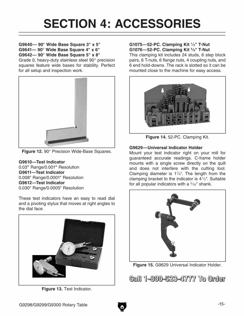
G9610—Test Indicator 0.03" range/0.001" resolutionG9611—Test Indicator0.008" range/0.0001" resolutionG9612—Test Indicator0.030" range/0.0005" resolution
these test indicators have an easy to read dial and a pivoting stylus that moves at right angles to the dial face.
G9640— 90° Wide Base Square 3" x 5"G9641— 90° Wide Base Square 4" x 6"G9642— 90° Wide Base Square 5" x 8"grade 0, heavy-duty stainless steel 90° precision squares feature wide bases for stability. perfect for all setup and inspection work.
figure 12. 90° precision Wide-Base squares.
G1075—52-pC. Clamping Kit 1⁄2" T-NutG1076—52-pC. Clamping Kit 5⁄8" T-Nutthis clamping kit includes 24 studs, 6 step block pairs, 6 t-nuts, 6 flange nuts, 4 coupling nuts, and 6 end hold-downs. the rack is slotted so it can be mounted close to the machine for easy access.
figure 14. 52-pC. Clamping Kit.
G9629—universal Indicator HolderMount your test indicator right on your mill for guaranteed accurate readings. C-frame holder mounts with a single screw directly on the quill and does not interfere with the cutting tool. Clamping diameter is 1 7⁄8". the length from the clamping bracket to the indicator is 4 1⁄2". suitable for all popular indicators with a 5⁄32" shank.
figure 15. g9629 universal indicator holder.

-16- g9298/g9299/g9300 rotary table
H2939—4 piece Edge finder SetFour different styles to cover any setup problem! set includes one each: a 3⁄8" diameter with a point, a combination 3⁄8" diameter with a point and a 0.200" shoulder, a 1⁄2" diameter with a 0.200" shoulder, and a combination 1⁄2" diameter with a 0.200" shoulder and a 0.500" shoulder.
figure 16. h2939 4-pc. edge Finder set.
G9296—Adjustable TailstockFor 8" and 10" rotary tablesG9297—Adjustable TailstockFor 12" rotary tablesWhen used with your rotary table and mill, these adjustable tailstocks provide the support you need for those longer workpieces. Clamps to your mill table with standard clamping hardware and allows precise and accurate adjustments.
figure 17. Adjustable tailstock.
G9295—Dividing platesWhen used with your rotary table, these dividing plates provide a higher degree of precision in hole placement, spot facing, and even gear making.
figure 18. g9295 dividing plates.
H8370—power feed for Millsif you want to get the most out of your mill, you really need a power feed. this power feed comes with everything required to start milling with exact control. Comes supplied with a mounting bracket, gear, auto-stop limit switch with moveable stop pins, gear guard, and motor. specs: 0–140 rpM, 200 rpM rapid switch, 440 in/lb. maximum torque, 110V 60hz motor, 4:1 bevel drive gear.
figure 19. h8370 power Feed.

-17-g9298/g9299/g9300 rotary table
SECTION 5: MAINTENANCE
For optimum performance from your machine, follow this maintenance schedule and refer to any specific instructions given in this section.
Daily:• Clean and lubricate the machine• dress the machined surfaces.• Check/fill the oil reservoir.• Check/resolve any unsafe condition.
Monthly:• disassembly and clean the machine.
Schedule
Cleaning
Lubrication
it is essential that the rotary table be cleaned after every use and oiled with a light machine oil to prevent corrosion.
do not use compressed air to clean your rotary table. Chips or debris may become lodged between the moving parts, reducing the life and accuracy of the machine. instead, use a stiff-bristled brush to remove the chips and swarf, then wipe down the surfaces with a clean shop rag.
every 80 hours of use, completely disassembly the rotary table, then thoroughly clean each part and re-lubricate.
place the rotary table in a horizontal position and check the oil site glass located on the back side of the base (see figure 20). if necessary, add a high-quality 80W–90W gear oil until the oil level reaches half-way in the site glass.
figure 20. lubrication components.
sightglass
oilport
Ball BearingBall oiler
the ball bearing ball oiler is located on the edge of the rotary table (see figure 20). With the rotary table positioned vertically, use a squirt-gun style oiler to add one or two pumps of 20W non-deter-gent oil to the ball oiler per day.

-18- g9298/g9299/g9300 rotary table
Surface Care
nicks, dings, and scratches on the surface of the rotary table and base can have an adverse effect on accuracy and may damage the workpiece or mill table.
prior to use, dress or "stoning" these surfaces with a fine sharpening stone. A few strokes of the stone on the table surface, the machined base and back, and the mill table will help to ensure longevity and accuracy. Make sure to thoroughly wipe these surfaces clean to remove any dust generated from the process.
preload
A precision spacer is installed under the keeper on the back of the rotary table to maintain the proper amount of preload. With use, the spacer surface that the keeper rubs against may become worn.
you can test the preload by mounting the rotary table horizontally on the mill table, positioning the tip of a test indicator on the surface of the rotary table, then attempting to lift the table up from the base. the table is properly preloaded when no motion is measured. if motion is detected by the test indicator, perform the procedure below to cor-rect the amount of preload.
Tools Needed Qtyhex Wrench 5mm .............................................. 1Fine sharpening stone ...................................... 1
To correct the amount of preload:
1. turn the rotary table horizontally upside down on a protected surface.
2. remove the three cap screws shown in figure 21 that secure the keeper.
figure 21. Keeper and cap screws.
Keeper
3. remove the keeper and the spacer (see figure 22).
figure 22. Keeper and spacer removed from the rotary table.
spacer
Keeper(shown upside
down)
4. stone the spacer as instructed in the previ-ous Surface Care subsection on this page.
5. thoroughly clean all of the mating surfaces, then apply a thin coat of light machine oil to all parts.
6. re-assembly the parts and test the preload again. if necessary, repeat this procedure until you have attained the proper amount of preload.

CU
T A
LON
G D
OT
TE
D L
INE
Name _____________________________________________________________________________
Street _____________________________________________________________________________
City _______________________ State _________________________ Zip _____________________
Phone # ____________________ Email ________________________ Invoice # _________________
Model # ____________________ Order # _______________________ Serial # __________________
WARRANTY CARD
The following information is given on a voluntary basis. It will be used for marketing purposes to help us develop better products and services. Of course, all information is strictly confidential.
1. How did you learn about us? ____ Advertisement ____ Friend ____ Catalog ____ Card Deck ____ Website ____ Other:
2. Which of the following magazines do you subscribe to?
3. What is your annual household income? ____ $20,000-$29,000 ____ $30,000-$39,000 ____ $40,000-$49,000 ____ $50,000-$59,000 ____ $60,000-$69,000 ____ $70,000+
4. What is your age group? ____ 20-29 ____ 30-39 ____ 40-49 ____ 50-59 ____ 60-69 ____ 70+
5. How long have you been a woodworker/metalworker? ____ 0-2 Years ____ 2-8 Years ____ 8-20 Years ____20+ Years
6. How many of your machines or tools are Grizzly? ____ 0-2 ____ 3-5 ____ 6-9 ____10+
7. Do you think your machine represents a good value? _____Yes _____No
8. Would you recommend Grizzly Industrial to a friend? _____Yes _____No
9. Would you allow us to use your name as a reference for Grizzly customers in your area? Note: We never use names more than 3 times. _____Yes _____No
10. Comments: _____________________________________________________________________
_________________________________________________________________________________
_________________________________________________________________________________
_________________________________________________________________________________
____ Cabinet Maker____ Family Handyman____ Hand Loader____ Handy____ Home Shop Machinist____ Journal of Light Cont.____ Live Steam____ Model Airplane News____ Modeltec____ Old House Journal
____ Popular Mechanics____ Popular Science____ Popular Woodworking____ Practical Homeowner____ Precision Shooter____ Projects in Metal____ RC Modeler____ Rifle____ Shop Notes____ Shotgun News
____ Today’s Homeowner____ Wood____ Wooden Boat____ Woodshop News____ Woodsmith____ Woodwork____ Woodworker West____ Woodworker’s Journal____ Other:

TAPE ALONG EDGES--PLEASE DO NOT STAPLE
FOLD ALONG DOTTED LINE
FOLD ALONG DOTTED LINE
GRIZZLY INDUSTRIAL, INC.P.O. BOX 2069BELLINGHAM, WA 98227-2069
PlaceStampHere
Name_______________________________
Street_______________________________
City______________State______Zip______
Send a Grizzly Catalog to a friend:

WARRANTY AND RETuRNS
Grizzly Industrial, Inc. warrants every product it sells for a period of 1 year to the original purchaser from the date of purchase. This warranty does not apply to defects due directly or indirectly to misuse, abuse, negligence, accidents, repairs or alterations or lack of maintenance. This is Grizzly’s sole written warranty and any and all warranties that may be implied by law, including any merchantability or fitness, for any par-ticular purpose, are hereby limited to the duration of this written warranty. We do not warrant or represent that the merchandise complies with the provisions of any law or acts unless the manufacturer so warrants. In no event shall Grizzly’s liability under this warranty exceed the purchase price paid for the product and any legal actions brought against Grizzly shall be tried in the State of Washington, County of Whatcom.
We shall in no event be liable for death, injuries to persons or property or for incidental, contingent, special, or consequential damages arising from the use of our products.
To take advantage of this warranty, contact us by mail or phone and give us all the details. We will then issue you a “Return Number,’’ which must be clearly posted on the outside as well as the inside of the carton. We will not accept any item back without this number. Proof of purchase must accompany the merchandise.
The manufacturers reserve the right to change specifications at any time because they constantly strive to achieve better quality equipment. We make every effort to ensure that our products meet high quality and durability standards and we hope you never need to use this warranty.
Please feel free to write or call us if you have any questions about the machine or the manual.
Thank you again for your business and continued support. We hope to serve you again soon.
WARRANTY AND RETURNS

Buy Direct and Save with Grizzly® – Trusted, Proven and a Great Value!
-OR-
~Since 1983~
• SECURE ORDERING
• ORDERS SHIPPED WITHIN 24 HOURS
Visit Our Website Today For Current Information On Events And Specials!
Call Today For A FREEFull Color Catalog