Embed Size (px)
Citation preview

MODEL G0736/G0737VARIABLE-SPEED
VERTICAL METAL BANDSAWOWNER'S MANUAL
(For models manufactured since 3/14)
COPYRIGHT © FEBRUARY, 2012 BY GRIZZLY INDUSTRIAL, INC., REVISED MARCH, 2014 (DM)WARNING: NO PORTION OF THIS MANUAL MAY BE REPRODUCED IN ANY SHAPE
OR FORM WITHOUT THE WRITTEN APPROVAL OF GRIZZLY INDUSTRIAL, INC.#TS14540 PRINTED IN TAIWAN V3.03.14
Model G0737 Shown

This manual provides critical safety instructions on the proper setup, operation, maintenance, and service of this machine/tool. Save this document, refer to it often, and use it to instruct other operators.
Failure to read, understand and follow the instructions in this manual may result in fire or serious personal injury—including amputation, electrocution, or death.
The owner of this machine/tool is solely responsible for its safe use. This responsibility includes but is not limited to proper installation in a safe environment, personnel training and usage authorization, proper inspection and maintenance, manual availability and compre-hension, application of safety devices, cutting/sanding/grinding tool integrity, and the usage of personal protective equipment.
The manufacturer will not be held liable for injury or property damage from negligence, improper training, machine modifications or misuse.
Some dust created by power sanding, sawing, grinding, drilling, and other construction activities contains chemicals known to the State of California to cause cancer, birth defects or other reproductive harm. Some examples of these chemicals are:
• Lead from lead-based paints.• Crystalline silica from bricks, cement and other masonry products.• Arsenic and chromium from chemically-treated lumber.
Your risk from these exposures varies, depending on how often you do this type of work. To reduce your exposure to these chemicals: Work in a well ventilated area, and work with approved safety equip-ment, such as those dust masks that are specially designed to filter out microscopic particles.

Table of ContentsINTRODUCTION ............................................... 2
Manual Accuracy ........................................... 2Contact Info.................................................... 2Cutting Overview............................................ 2Identification ................................................... 3Basic Controls ................................................ 4Machine Data Sheet ...................................... 6
SECTION 1: SAFETY ....................................... 8Safety Instructions for Machinery .................. 8Additional Safety forMetal-Cutting Bandsaws .............................. 10
SECTION 2: POWER SUPPLY ...................... 11Availability .................................................. 11Full-Load Current Rating ........................... 11Circuit Requirements for 220V .................. 11Grounding Instructions .............................. 12Extension Cords ........................................ 12Power Cord Installation ............................. 13
SECTION 3: SETUP ....................................... 14Setup Overview............................................ 14Needed for Setup ......................................... 14Unpacking .................................................... 14Inventory ...................................................... 15Cleanup ........................................................ 15Site Considerations ...................................... 16Mounting ...................................................... 17
Bolting to Concrete Floors ......................... 17Using Machine Mounts .............................. 17
Lifting & Placing ........................................... 18Assembly ..................................................... 18Tensioning & Tracking Blade ....................... 19
Tensioning Blade ....................................... 19Tracking Blade ........................................... 19
Adjusting Blade Guide Assemblies .............. 21Blade Support Adjustment ......................... 22Blade Guide Adjustments .......................... 22
Power Connection........................................ 23Connecting Power ..................................... 23Disconnecting Power ................................. 23
Test Run ...................................................... 24
SECTION 4: OPERATIONS ........................... 26Operation Overview ..................................... 26Disabling & Locking Bandsaw Power Switch 27Adjusting Table Tilt ...................................... 28
Adjusting Side-to-Side Table Tilt ............... 28Adjusting Front-to-Back Table Tilt ............. 28
Blade Selection ............................................ 29Blade Terminology ..................................... 29Blade Length ............................................. 29
Blade Width ............................................... 29Tooth Set ................................................... 30Tooth Type ................................................ 30Blade Pitch (TPI) ....................................... 31
Blade Breakage ........................................... 32Blade Care & Break-In ................................. 32Chip Inspection Chart .................................. 33Blade Changes ............................................ 34Guide Post ................................................... 35Blade Shear ................................................. 35Blade Welding .............................................. 35
SECTION 5: ACCESSORIES ......................... 39
SECTION 6: MAINTENANCE ......................... 41Schedule ...................................................... 41Cleaning ....................................................... 41Redressing Rubber Tires ............................. 41Lubrication ................................................... 42
Guide Post Rack ....................................... 42Tension Leadscrew ................................... 42Variable Speed Pulley Shaft ...................... 43Air Pump .................................................... 43
SECTION 7: SERVICE ................................... 44Troubleshooting ........................................... 44
Motor & Electrical ...................................... 44Cutting Operations ..................................... 45
Replacing V-Belts ........................................ 46Wheel Alignment .......................................... 46
Checking Wheel Alignment ....................... 46Laterally Adjusting Top Wheel ................... 47Shimming Wheel ....................................... 48
Blade Guides & Supports ............................ 48Calibrating Table Tilt Scales ........................ 49
SECTION 8: WIRING ...................................... 50Wiring Safety Instructions ............................ 50Electrical Wiring Overview ........................... 51Control Panel Wiring Diagram ..................... 52Control Panel Wiring Photo ......................... 53Welding Station Wiring Photo ...................... 53Welding Station Wiring Diagram .................. 54Additional Component Wiring Diagrams ...... 55
SECTION 9: PARTS ....................................... 56Cabinet & Wheels ........................................ 56Motor & Drive System .................................. 58Table & Guides ............................................ 60Control Panel & Blade Shear ....................... 62Welding Station ............................................ 63Machine Labels ............................................ 65
WARRANTY & RETURNS ............................. 69
-2- Model G0736/G0737 (Mfd. Since 3/14)
INTRODUCTION
We are proud to offer this manual with your new machine! We've made every effort to be exact with the instructions, specifications, drawings, and photographs of the machine we used when writing this manual. However, sometimes we still make an occasional mistake.
Also, owing to our policy of continuous improve-ment, your machine may not exactly match the manual. If you find this to be the case, and the dif-ference between the manual and machine leaves you in doubt, check our website for the latest manual update or call technical support for help.
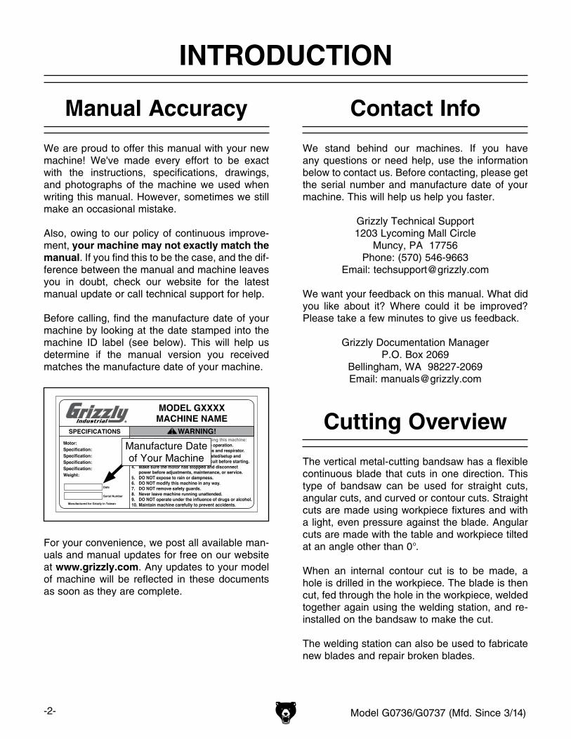
Before calling, find the manufacture date of your machine by looking at the date stamped into the machine ID label (see below). This will help us determine if the manual version you received matches the manufacture date of your machine.
For your convenience, we post all available man-uals and manual updates for free on our website at www.grizzly.com. Any updates to your model of machine will be reflected in these documents as soon as they are complete.
Manufacture Date of Your Machine
Manual Accuracy
We stand behind our machines. If you have any questions or need help, use the information below to contact us. Before contacting, please get the serial number and manufacture date of your machine. This will help us help you faster.
Grizzly Technical Support1203 Lycoming Mall Circle
Muncy, PA 17756Phone: (570) 546-9663
Email: [email protected]
We want your feedback on this manual. What did you like about it? Where could it be improved? Please take a few minutes to give us feedback.
Grizzly Documentation ManagerP.O. Box 2069
Bellingham, WA 98227-2069Email: [email protected]
Contact Info
Cutting Overview
The vertical metal-cutting bandsaw has a flexible continuous blade that cuts in one direction. This type of bandsaw can be used for straight cuts, angular cuts, and curved or contour cuts. Straight cuts are made using workpiece fixtures and with a light, even pressure against the blade. Angular cuts are made with the table and workpiece tilted at an angle other than 0°.
When an internal contour cut is to be made, a hole is drilled in the workpiece. The blade is then cut, fed through the hole in the workpiece, welded together again using the welding station, and re-installed on the bandsaw to make the cut.
The welding station can also be used to fabricate new blades and repair broken blades.
Model G0736/G0737 (Mfd. Since 3/14) -3-
Identification
To reduce the risk of serious injury when using this machine, read and understand this entire manual before beginning any operations.
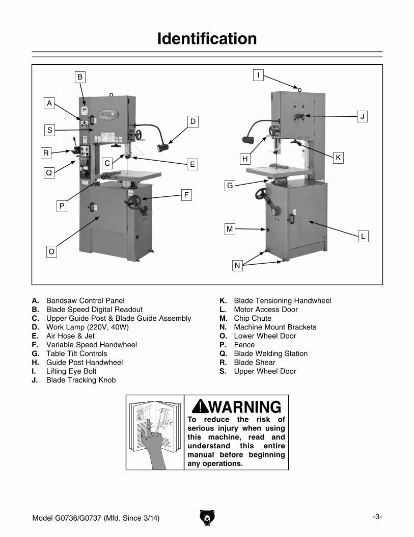
A. Bandsaw Control PanelB. Blade Speed Digital ReadoutC. Upper Guide Post & Blade Guide AssemblyD. Work Lamp (220V, 40W)E. Air Hose & JetF. Variable Speed HandwheelG. Table Tilt ControlsH. Guide Post HandwheelI. Lifting Eye BoltJ. Blade Tracking Knob
K. Blade Tensioning HandwheelL. Motor Access DoorM. Chip ChuteN. Machine Mount BracketsO. Lower Wheel DoorP. FenceQ. Blade Welding StationR. Blade ShearS. Upper Wheel Door
O
P
Q
R
S
EC
D
A
B
F
K
G
I
J
H
L
N
M
-4- Model G0736/G0737 (Mfd. Since 3/14)
Locking the bandsaw power switch DOES NOT disable the welding station functions. The machine must be disconnected from power to prevent the use of the welding sta-tion.
Basic Controls
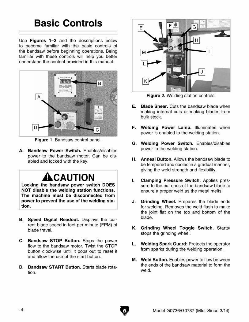
Use Figures 1–3 and the descriptions below to become familiar with the basic controls of the bandsaw before beginning operations. Being familiar with these controls will help you better understand the content provided in this manual.
A. Bandsaw Power Switch. Enables/disables power to the bandsaw motor. Can be dis-abled and locked with the key.
B. Speed Digital Readout. Displays the cur-rent blade speed in feet per minute (FPM) of blade travel.
C. Bandsaw STOP Button. Stops the power flow to the bandsaw motor. Twist the STOP button clockwise until it pops out to reset it and allow the use of the start button.
D. Bandsaw START Button. Starts blade rota-tion.
E. Blade Shear. Cuts the bandsaw blade when making internal cuts or making blades from bulk stock.
F. Welding Power Lamp. Illuminates when power is enabled to the welding station.
G. Welding Power Switch. Enables/disables power to the welding station.
H. Anneal Button. Allows the bandsaw blade to be tempered and cooled in a gradual manner, giving the weld strength and flexibility.
I. Clamping Pressure Switch. Applies pres-sure to the cut ends of the bandsaw blade to ensure a proper weld as the metal melts.
J. Grinding Wheel. Prepares the blade ends for welding. Removes the weld flash to make the joint flat on the top and bottom of the blade.
K. Grinding Wheel Toggle Switch. Starts/stops the grinding wheel.
L. Welding Spark Guard: Protects the operator from sparks during the welding operation.
M. Weld Button. Enables power to flow between the ends of the bandsaw material to form the weld.
Figure 1. Bandsaw control panel.
A
D C
B
Figure 2. Welding station controls.
E F G
H
M
K
J
I
L
Model G0736/G0737 (Mfd. Since 3/14) -5-
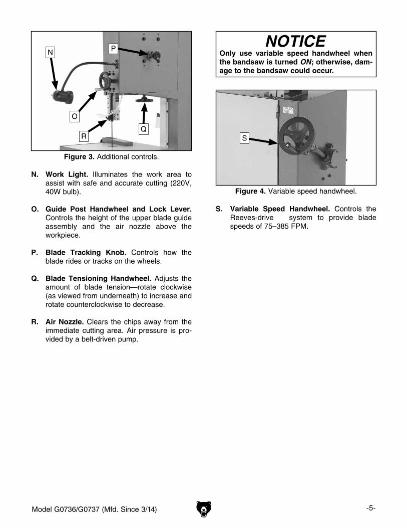
Figure 4. Variable speed handwheel.
S
S. Variable Speed Handwheel. Controls the Reeves-drive system to provide blade speeds of 75–385 FPM.
N. Work Light. Illuminates the work area to assist with safe and accurate cutting (220V, 40W bulb).
O. Guide Post Handwheel and Lock Lever. Controls the height of the upper blade guide assembly and the air nozzle above the workpiece.
P. Blade Tracking Knob. Controls how the blade rides or tracks on the wheels.
Q. Blade Tensioning Handwheel. Adjusts the amount of blade tension—rotate clockwise (as viewed from underneath) to increase and rotate counterclockwise to decrease.
R. Air Nozzle. Clears the chips away from the immediate cutting area. Air pressure is pro-vided by a belt-driven pump.
Only use variable speed handwheel when the bandsaw is turned ON; otherwise, dam-age to the bandsaw could occur.
Figure 3. Additional controls.
N
R
O
P
Q

-6- Model G0736/G0737 (Mfd. Since 3/14)
MODEL G0736/G0737VARIABLE-SPEED VERTICALMETAL-CUTTING BANDSAW
G0736 G0737Product Dimensions
Net Weight 732 lbs. 830 lbs.
Width (side-to-side) x Depth (front-to-back) x Height
33" x 27" x 70" 39 1⁄2" x 30" x 74 1⁄2"
Footprint (Length x Width) 17 1⁄4" x 29" 18" x 32"Shipping Dimensions
Shipping Weight 860 lbs. 970 lbs.
Length x Width x Height 39" x 29" x 78" 43" x 29" x 83"Electrical
Power Requirement 220V, 1-Phase, 60 Hz
Full Load Current Rating 11 Amps 12 Amps
Minimum Circuit Size 15 Amps
Switch ON/OFF Push Button, Master Magnetic Switch w/Locking Key
Switch Voltage 220V
Recommended Power Cord 14 AWG, 3 Wire, 300VAC
Recommended Plug/Receptacle NEMA 6-15Motors
Bandsaw
Type TEFC Capacitor Start Induction
Horsepower 1 1⁄2 HP 2 HP
Electrical 220V, 1-PH, 9 Amps 220V, 1-PH, 12 Amps
Power Transfer Variable-Speed Belt Drive
Grinding Wheel
Type Open Drip-Proof Induction
Horsepower 1⁄8 HP
Electrical 220V, 1-PH, 0.75 Amps
Power Transfer Direct Drive
Welder
Electrical 220V, 2.4KVA, 11A

Model G0736/G0737 (Mfd. Since 3/14) -7-
G0736 G0737Operation Information
Blade Speeds Variable, 75–385 FPM
Standard Blade Length 120" 140"
Blade Width Range 1⁄8" –5⁄8"Cutting Capacity
Cutting Height 10" 10 3⁄4"
Cutting Capacity Left of Blade 15" 18"Table Information
Table Tilt 15° Left/Right, 10° Front/Back
Length x Width x Thickness 23 5⁄8" x 21 5⁄8" x 1 3⁄4"
Floor to Table Height 39"Construction
Table Precision-Ground Cast Iron
Wheels Balance Cast Iron
Wheel Tires Rubber
Body & Doors Formed Steel
Paint Urethane
Other Information
Wheel Size 15 1⁄4" O.D. 18 1⁄4" O.D.
Blade Guide Type Steel Block
Country of Origin Taiwan
Warranty 1 Year
-8- Model G0736/G0737 (Mfd. Since 3/14)
ELECTRICAL EQUIPMENT INJURY RISKS. You can be shocked, burned, or killed by touching live electrical components or improperly grounded machinery. To reduce this risk, only allow qualified service personnel to do electrical installation or repair work, and always disconnect power before accessing or exposing electrical equipment.
DISCONNECT POWER FIRST. Always discon-nect machine from power supply BEFORE making adjustments, changing tooling, or servicing machine. This prevents an injury risk from unintended startup or contact with live electrical components.
EYE PROTECTION. Always wear ANSI-approved safety glasses or a face shield when operating or observing machinery to reduce the risk of eye injury or blindness from flying particles. Everyday eyeglasses are not approved safety glasses.
OWNER’S MANUAL. Read and understand this owner’s manual BEFORE using machine.
TRAINED OPERATORS ONLY. Untrained oper-ators have a higher risk of being hurt or killed. Only allow trained/supervised people to use this machine. When machine is not being used, dis-connect power, remove switch keys, or lock-out machine to prevent unauthorized use—especially around children. Make workshop kid proof!
DANGEROUS ENVIRONMENTS. Do not use machinery in areas that are wet, cluttered, or have poor lighting. Operating machinery in these areas greatly increases the risk of accidents and injury.
MENTAL ALERTNESS REQUIRED. Full mental alertness is required for safe operation of machin-ery. Never operate under the influence of drugs or alcohol, when tired, or when distracted.
For Your Own Safety, Read Instruction Manual Before Operating This Machine
The purpose of safety symbols is to attract your attention to possible hazardous conditions. This manual uses a series of symbols and signal words intended to convey the level of impor-tance of the safety messages. The progression of symbols is described below. Remember that safety messages by themselves do not eliminate danger and are not a substitute for proper accident prevention measures. Always use common sense and good judgment.
Indicates a potentially hazardous situation which, if not avoided, MAY result in minor or moderate injury. It may also be used to alert against unsafe practices.
Indicates a potentially hazardous situation which, if not avoided, COULD result in death or serious injury.
Indicates an imminently hazardous situation which, if not avoided, WILL result in death or serious injury.
This symbol is used to alert the user to useful information about proper operation of the machine.NOTICE
Safety Instructions for Machinery
SECTION 1: SAFETY
Model G0736/G0737 (Mfd. Since 3/14) -9-
WEARING PROPER APPAREL. Do not wearclothing, apparel or jewelry that can becomeentangled in moving parts. Always tie back orcover longhair.Wearnon-slip footwear toavoidaccidentalslips,whichcouldcauselossofwork-piececontrol.
hAzARdOus dusT. Dust created while usingmachinery may cause cancer, birth defects, orlong-term respiratorydamage.Beawareofdusthazardsassociatedwitheachworkpiecematerial,andalwayswearaNIOSH-approvedrespiratortoreduceyourrisk.
hEARING PROTECTION. Always wear hear-ing protectionwhenoperating or observing loudmachinery. Extended exposure to this noisewithouthearingprotectioncancausepermanenthearingloss.
REMOVE AdJusTING TOOLs. Tools left onmachinery can become dangerous projectilesuponstartup.Neverleavechuckkeys,wrenches,or any other tools on machine. Always verifyremovalbeforestarting!
INTENdEd usAGE. Only use machine for itsintendedpurposeandnevermakemodificationsnot approved by Grizzly. Modifying machine orusing it differently than intended may result inmalfunctionormechanicalfailurethatcanleadtoseriouspersonalinjuryordeath!
AWKWARd POsITIONs. Keep proper footingandbalanceatalltimeswhenoperatingmachine.Donotoverreach!Avoidawkwardhandpositionsthatmakeworkpiece control difficult or increasetheriskofaccidentalinjury.
ChILdREN & BYsTANdERs. Keepchildrenandbystandersatasafedistancefromtheworkarea.Stopusingmachineiftheybecomeadistraction.
GuARds & COVERs.Guardsandcoversreduceaccidental contact with moving parts or flyingdebris. Make sure they are properly installed,undamaged,andworkingcorrectly.
FORCING MAChINERY.Donotforcemachine.Itwilldo the jobsaferandbetterat the rate forwhichitwasdesigned.
NEVER sTANd ON MAChINE. Serious injurymay occur ifmachine is tipped or if the cuttingtoolisunintentionallycontacted.
sTABLE MAChINE. Unexpectedmovementdur-ing operation greatly increases risk of injury orlossofcontrol.Beforestarting,verifymachineisstableandmobilebase(ifused)islocked.
usE RECOMMENdEd ACCEssORIEs.Consultthisowner’smanualorthemanufacturerforrec-ommended accessories.Using improper acces-sorieswillincreasetheriskofseriousinjury.
uNATTENdEd OPERATION. To reduce therisk of accidental injury, turnmachineoff andensure all moving parts completely stop beforewalking away. Never leave machine runningwhileunattended.
MAINTAIN WITh CARE.Followallmaintenanceinstructions and lubrication schedules to keepmachine in good working condition. A machinethat is improperlymaintained couldmalfunction,leadingtoseriouspersonalinjuryordeath.
ChECK dAMAGEd PARTs. Regularly inspectmachine for any condition that may affect safeoperation.Immediatelyrepairorreplacedamagedormis-adjustedpartsbeforeoperatingmachine.
MAINTAIN POWER CORds. Whendisconnect-ing cord-connected machines from power, grabandpulltheplug—NOTthecord.Pullingthecordmay damage the wires inside. Do not handlecord/plugwithwethands.Avoidcorddamagebykeepingitawayfromheatedsurfaces,hightrafficareas,harshchemicals,andwet/damplocations.
EXPERIENCING dIFFICuLTIEs. If at any timeyouexperiencedifficultiesperformingtheintend-edoperation,stopusingthemachine!ContactourTechnicalSupportat(570)546-9663.
-10- Model G0736/G0737 (Mfd. Since 3/14)
BLADE CONDITION. Do not operate with dull, cracked or badly worn blade that can break dur-ing operation or decrease the performance of the bandsaw. Inspect blades for cracks and missing teeth before each use.
BLADE REPLACEMENT. Wear gloves to protect hands and safety glasses to protect eyes when replacing the blade. When replacing blade, make sure teeth face forward and down toward the table in the direction of blade travel.
WORKPIECE HANDLING. Your hands can be drawn into the blade during operation if the workpiece moves unexpectedly. Always keep your hands a safe distance away from the moving blade.
FIRE HAZARD. Use EXTREME CAUTION if cut-ting magnesium. Using the wrong cutting fluid will lead to chip fire and possible explosion.
WELDING AND GRINDING SAFETY. The weld-ing station represents a serious burn hazard. DO NOT touch any metal parts of the blade, welder, or machine when activating the welder. Keep your hands a safe distance away from the grinding wheel when in use.
HOT SURFACES. Be aware that touching hot workpieces or chips after welding, grinding, or cutting can cause burns.
CUTTING FLUID SAFETY. Cutting fluids are poisonous. Always follow manufacturer’s cutting-fluid safety instructions. Pay particular attention to contact, contamination, inhalation, storage and disposal warnings. Spilled cutting fluid invites slip-ping hazards.
ENTANGLEMENT HAZARDS. Always keep the blade guard correctly positioned and wheel doors closed and secured when bandsaw is in opera-tion. Loose clothing, jewelry, long hair and work gloves could be pulled into the blade or moving parts, resulting in lacerations or amputation.
MAINTENANCE/SERVICE. Perform all inspec-tions, adjustments, and maintenance with the power OFF and the plug pulled from the outlet to prevent unexpected start up. Wait for all moving parts to come to a complete stop before starting.
UNSTABLE WORKPIECES. Workpieces that cannot be supported or stabilized without a vise or jig should not be cut on a vertical metal-cutting bandsaw, because they can unexpectedly move while cutting and draw the operator's hands into the blade causing serious personal injury. Examples are chains, cables, round or oblong-shaped workpieces, workpieces with internal or built-in moving or rotations parts, etc.
Additional Safety for Metal-Cutting Bandsaws
Like all machinery there is potential danger when operating this machine. Accidents are frequently caused by lack of familiarity or failure to pay attention. Use this machine with respect and caution to decrease the risk of operator injury. If normal safety pre-cautions are overlooked or ignored, seri-ous personal injury may occur.
No list of safety guidelines can be com-plete. Every shop environment is different. Always consider safety first, as it applies to your individual working conditions. Use this and other machinery with caution and respect. Failure to do so could result in serious personal injury, damage to equip-ment, or poor work results.

Model G0736/G0737 (Mfd. Since 3/14) -11-
SECTION 2: POWER SUPPLY
AvailabilityBefore installing the machine, consider the avail-ability and proximity of the required power supply circuit. If an existing circuit does not meet the requirements for this machine, a new circuit must be installed. To minimize the risk of electrocution, fire, or equipment damage, installation work and electrical wiring must be done by an electrican or qualified service personnel in accordance with all applicable codes and standards.
Electrocution, fire, or equipment damage may occur if machine is not correctly grounded and connected to the power supply.
Full-Load Current RatingThe full-load current rating is the amperage a machine draws at 100% of the rated output power. On machines with multiple motors, this is the amperage drawn by the largest motor or sum of all motors and electrical devices that might operate at one time during normal operations.
G0736 Full-Load Current Rating ........ 11 AmpsG0737 Full-Load Current Rating ........ 12 Amps
The full-load current is not the maximum amount of amps that the machine will draw. If the machine is overloaded, it will draw additional amps beyond the full-load rating.
If the machine is overloaded for a sufficient length of time, damage, overheating, or fire may result—especially if connected to an undersized circuit. To reduce the risk of these hazards, avoid over-loading the machine during operation and make sure it is connected to a power supply circuit that meets the requirements in the following section.
Circuit Requirements for 220VThis machine is prewired to operate on a 220V power supply circuit that has a verified ground and meets the following requirements:
Nominal Voltage .............................. 220V/240VCycle ..........................................................60 HzPhase .................................................... 1-PhasePower Supply Circuit ......................... 15 AmpsPlug/Receptacle ............................. NEMA 6-15Power Cord ..“S”-Type, 3-Wire, 14 AWG, 300V
For your own safety and protection of property, consult an electrician if you are unsure about wiring practices or electrical codes in your area.
Note: The circuit requirements listed in this man-ual apply to a dedicated circuit—where only one machine will be running at a time. If this machine will be connected to a shared circuit where mul-tiple machines will be running at the same time, consult a qualified electrician to ensure that the circuit is properly sized for safe operation.
A power supply circuit includes all electrical equipment between the breaker box or fuse panel in the building and the machine. The power sup-ply circuit used for this machine must be sized to safely handle the full-load current drawn from the machine for an extended period of time. (If this machine is connected to a circuit protected by fuses, use a time delay fuse marked D.)
Serious injury could occur if you connect the machine to power before completing the setup process. DO NOT connect to power until instructed later in this manual.
-12- Model G0736/G0737 (Mfd. Since 3/14)
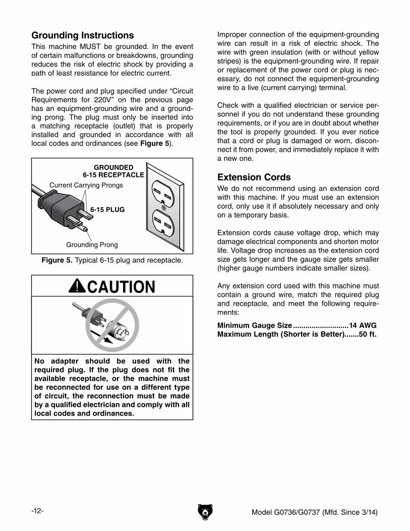
Extension CordsWe do not recommend using an extension cord with this machine. If you must use an extension cord, only use it if absolutely necessary and only on a temporary basis.
Extension cords cause voltage drop, which may damage electrical components and shorten motor life. Voltage drop increases as the extension cord size gets longer and the gauge size gets smaller (higher gauge numbers indicate smaller sizes).
Any extension cord used with this machine must contain a ground wire, match the required plug and receptacle, and meet the following require-ments:
Minimum Gauge Size ...........................14 AWGMaximum Length (Shorter is Better).......50 ft.
Grounding InstructionsThis machine MUST be grounded. In the event of certain malfunctions or breakdowns, grounding reduces the risk of electric shock by providing a path of least resistance for electric current.
Improper connection of the equipment-grounding wire can result in a risk of electric shock. The wire with green insulation (with or without yellow stripes) is the equipment-grounding wire. If repair or replacement of the power cord or plug is nec-essary, do not connect the equipment-grounding wire to a live (current carrying) terminal. Check with a qualified electrician or service per-sonnel if you do not understand these grounding requirements, or if you are in doubt about whether the tool is properly grounded. If you ever notice that a cord or plug is damaged or worn, discon-nect it from power, and immediately replace it with a new one.
No adapter should be used with the required plug. If the plug does not fit the available receptacle, or the machine must be reconnected for use on a different type of circuit, the reconnection must be made by a qualified electrician and comply with all local codes and ordinances.
The power cord and plug specified under “Circuit Requirements for 220V” on the previous page has an equipment-grounding wire and a ground-ing prong. The plug must only be inserted into a matching receptacle (outlet) that is properly installed and grounded in accordance with all local codes and ordinances (see Figure 5).
Figure 5. Typical 6-15 plug and receptacle.
Grounding Prong
Current Carrying Prongs
6-15 PLUG
GROUNDED6-15 RECEPTACLE
Model G0736/G0737 (Mfd. Since 3/14) -13-
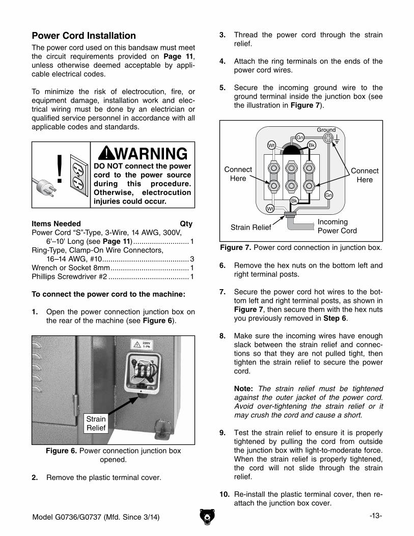
Power Cord InstallationThe power cord used on this bandsaw must meet the circuit requirements provided on Page 11, unless otherwise deemed acceptable by appli-cable electrical codes.
To minimize the risk of electrocution, fire, or equipment damage, installation work and elec-trical wiring must be done by an electrician or qualified service personnel in accordance with all applicable codes and standards.
Figure 6. Power connection junction box opened.
StrainRelief
Ground
IncomingPower Cord
ConnectHere
ConnectHere
Strain Relief
Figure 7. Power cord connection in junction box.
6. Remove the hex nuts on the bottom left and right terminal posts.
7. Secure the power cord hot wires to the bot-tom left and right terminal posts, as shown in Figure 7, then secure them with the hex nuts you previously removed in Step 6.
8. Make sure the incoming wires have enough slack between the strain relief and connec-tions so that they are not pulled tight, then tighten the strain relief to secure the power cord.
Note: The strain relief must be tightened against the outer jacket of the power cord. Avoid over-tightening the strain relief or it may crush the cord and cause a short.
9. Test the strain relief to ensure it is properly tightened by pulling the cord from outside the junction box with light-to-moderate force. When the strain relief is properly tightened, the cord will not slide through the strain relief.
10. Re-install the plastic terminal cover, then re-attach the junction box cover.
Items Needed QtyPower Cord “S”-Type, 3-Wire, 14 AWG, 300V, 6'–10' Long (see Page 11) ........................... 1Ring-Type, Clamp-On Wire Connectors, 16–14 AWG, #10 .......................................... 3Wrench or Socket 8mm ...................................... 1Phillips Screwdriver #2 ....................................... 1
To connect the power cord to the machine:
1. Open the power connection junction box on the rear of the machine (see Figure 6).
DO NOT connect the power cord to the power source during this procedure. Otherwise, electrocution injuries could occur.
3. Thread the power cord through the strain relief.
4. Attach the ring terminals on the ends of the power cord wires.
5. Secure the incoming ground wire to the ground terminal inside the junction box (see the illustration in Figure 7).
2. Remove the plastic terminal cover.
-14- Model G0736/G0737 (Mfd. Since 3/14)
SECTION 3: SETUP
Your machine was carefully packaged for safe transportation. Remove the packaging materials from around your machine and inspect it. If you discover any damage, please call us immediately at (570) 546-9663 for advice.
Save the containers and all packing materials for possible inspection by the carrier or its agent. Otherwise, filing a freight claim can be difficult.
When you are completely satisfied with the condi-tion of your shipment, inventory the contents.
Unpacking
SUFFOCATION HAZARD!Keep children and pets away from plastic bags or packing materials shipped with this machine. Discard immediately.
The following are needed to complete the setup process, but are not included with your machine.
Description Qty• Additional People ........................................ 1• Safety Glasses ................. 1 for Each Person• Cleaner/Degreaser ...................... As Needed• Disposable Shop Rags ................ As Needed• Forklift (rated for at least 1000 lbs.) ............. 1• Safety Hook & Chain (rated for at lease 1000 lbs. each) ......1 Each• Floor Mounting Hardware 5⁄8" ...... As Needed
Needed for SetupSetup Overview
The purpose of the setup section is to help you prepare your machine for operation. The list below outlines this basic process. Specific steps for each of these points will be covered in detail later in this section.
The bandsaw is a complex machine that requires a number of adjustments to operate safely and efficiently. Be sure to perform all of the instruc-tions in this section in sequence.
The typical setup process is as follows:
1. Unpack the bandsaw and inventory the loose components.
2. Clean the bandsaw and its components.
3. Move the bandsaw to an acceptable loca-tion.
4. Tension the blade.
5. Check/adjust the blade tracking.
6. Check/adjust the blade guide assemblies.
7. Connect the bandsaw to the power source.
8. Test run the bandsaw to make sure it func-tions properly.
Model G0736/G0737 (Mfd. Since 3/14) -15-
NOTICEIf you cannot find an item on this list, care-fully check around/inside the machine and packaging materials. Often, these items get lost in packaging materials while unpack-ing or they are pre-installed at the factory.
Inventory
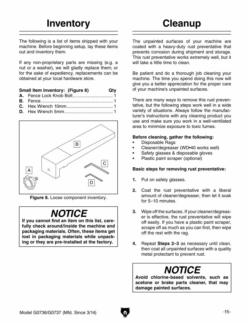
The following is a list of items shipped with your machine. Before beginning setup, lay these items out and inventory them.
If any non-proprietary parts are missing (e.g. a nut or a washer), we will gladly replace them; or for the sake of expediency, replacements can be obtained at your local hardware store.
Small Item Inventory: (Figure 8) QtyA. Fence Lock Knob Bolt ................................ 1B. Fence.......................................................... 1C. Hex Wrench 10mm ..................................... 1D. Hex Wrench 5mm ....................................... 1
Figure 8. Loose component inventory.
A
B
C
D
Cleanup
The unpainted surfaces of your machine are coated with a heavy-duty rust preventative that prevents corrosion during shipment and storage. This rust preventative works extremely well, but it will take a little time to clean.
Be patient and do a thorough job cleaning your machine. The time you spend doing this now will give you a better appreciation for the proper care of your machine's unpainted surfaces.
There are many ways to remove this rust preven-tative, but the following steps work well in a wide variety of situations. Always follow the manufac-turer’s instructions with any cleaning product you use and make sure you work in a well-ventilated area to minimize exposure to toxic fumes.
Before cleaning, gather the following:• Disposable Rags• Cleaner/degreaser (WD•40 works well)• Safety glasses & disposable gloves• Plastic paint scraper (optional)
Basic steps for removing rust preventative:
1. Put on safety glasses.
2. Coat the rust preventative with a liberal amount of cleaner/degreaser, then let it soak for 5–10 minutes.
3. Wipe off the surfaces. If your cleaner/degreas-er is effective, the rust preventative will wipe off easily. If you have a plastic paint scraper, scrape off as much as you can first, then wipe off the rest with the rag.
4. Repeat Steps 2–3 as necessary until clean, then coat all unpainted surfaces with a quality metal protectant to prevent rust.
NOTICEAvoid chlorine-based solvents, such as acetone or brake parts cleaner, that may damage painted surfaces.
-16- Model G0736/G0737 (Mfd. Since 3/14)
Site Considerations
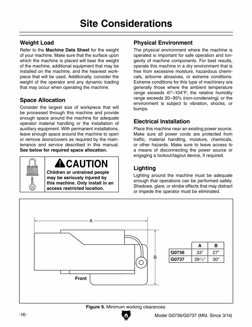
Figure 9. Minimum working clearances.
A
B
Front
Weight LoadRefer to the Machine Data Sheet for the weight of your machine. Make sure that the surface upon which the machine is placed will bear the weight of the machine, additional equipment that may be installed on the machine, and the heaviest work-piece that will be used. Additionally, consider the weight of the operator and any dynamic loading that may occur when operating the machine.
Space AllocationConsider the largest size of workpiece that will be processed through this machine and provide enough space around the machine for adequate operator material handling or the installation of auxiliary equipment. With permanent installations, leave enough space around the machine to open or remove doors/covers as required by the main-tenance and service described in this manual. See below for required space allocation.
Physical EnvironmentThe physical environment where the machine is operated is important for safe operation and lon-gevity of machine components. For best results, operate this machine in a dry environment that is free from excessive moisture, hazardous chemi-cals, airborne abrasives, or extreme conditions. Extreme conditions for this type of machinery are generally those where the ambient temperature range exceeds 41°–104°F; the relative humidity range exceeds 20–95% (non-condensing); or the environment is subject to vibration, shocks, or bumps.
Electrical InstallationPlace this machine near an existing power source. Make sure all power cords are protected from traffic, material handling, moisture, chemicals, or other hazards. Make sure to leave access to a means of disconnecting the power source or engaging a lockout/tagout device, if required.
LightingLighting around the machine must be adequate enough that operations can be performed safely. Shadows, glare, or strobe effects that may distract or impede the operator must be eliminated.
Children or untrained people may be seriously injured by this machine. Only install in an access restricted location.
A B
G0736 33" 27"
G0737 39 1⁄2" 30"
Model G0736/G0737 (Mfd. Since 3/14) -17-
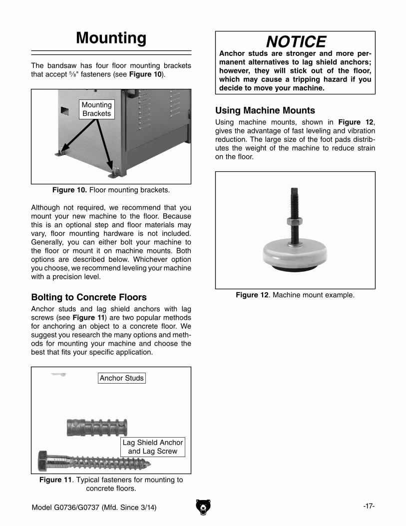
The bandsaw has four floor mounting brackets that accept 5⁄8" fasteners (see Figure 10).
Mounting
Figure 12. Machine mount example.
Using Machine MountsUsing machine mounts, shown in Figure 12, gives the advantage of fast leveling and vibration reduction. The large size of the foot pads distrib-utes the weight of the machine to reduce strain on the floor.
NOTICEAnchor studs are stronger and more per-manent alternatives to lag shield anchors; however, they will stick out of the floor, which may cause a tripping hazard if you decide to move your machine.
Figure 11. Typical fasteners for mounting to concrete floors.
Anchor Studs
Lag Shield Anchor and Lag Screw
Although not required, we recommend that you mount your new machine to the floor. Because this is an optional step and floor materials may vary, floor mounting hardware is not included. Generally, you can either bolt your machine to the floor or mount it on machine mounts. Both options are described below. Whichever option you choose, we recommend leveling your machine with a precision level.
Bolting to Concrete FloorsAnchor studs and lag shield anchors with lag screws (see Figure 11) are two popular methods for anchoring an object to a concrete floor. We suggest you research the many options and meth-ods for mounting your machine and choose the best that fits your specific application.
Figure 10. Floor mounting brackets.
MountingBrackets
-18- Model G0736/G0737 (Mfd. Since 3/14)
Lifting & Placing
This is a heavy machine. Serious personal injury may occur if safe moving methods are not used. To be safe, get assistance and use powered lifting equip-ment to move the ship-ping crate and remove the machine from the crate.
To lift and place the bandsaw:
1. Prepare the bandsaw operation site for machine placement (refer to Page 17) and electrical connection (refer to Page 11).
2. With the bandsaw still bolted to the shipping pallet, move it to the operation site, then unbolt the bandsaw from the pallet.
3. Attach the safety hook and chain between the forklift and the bandsaw lifting eyebolt (see Figure 13 for an example).
Figure 13. Example of using safety hook and chain to lift the bandsaw.
4. With the help from another person to steady the load, lift the bandsaw enough to clear the pallet, remove the pallet, then slowly place the bandsaw into position.
Assembly
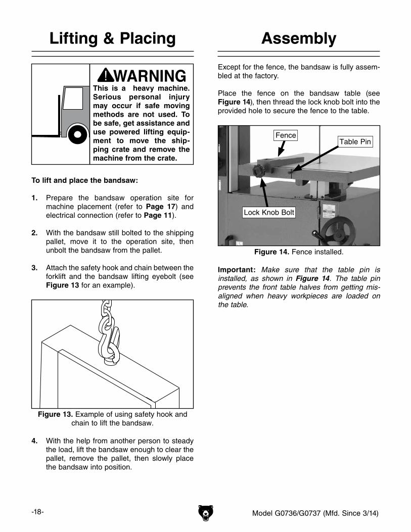
Except for the fence, the bandsaw is fully assem-bled at the factory.
Place the fence on the bandsaw table (see Figure 14), then thread the lock knob bolt into the provided hole to secure the fence to the table.
Important: Make sure that the table pin is installed, as shown in Figure 14. The table pin prevents the front table halves from getting mis-aligned when heavy workpieces are loaded on the table.
Figure 14. Fence installed.
Fence
Lock Knob Bolt
Table Pin
Model G0736/G0737 (Mfd. Since 3/14) -19-
Tensioning & Tracking Blade
Blade tension directly affects blade tracking so it is important to adjust them together.
Tensioning BladeProper blade tension maximizes the life of the blade and bandsaw components, improves cut-ting performance, and reduces the risks related to blade breakage.
When tensioning the blade, avoid the urge to over-tension it. Too much tension reduces the life of the bandsaw bearings and the blade.
To tension the blade:
1. DISCONNECT BANDSAW FROM POWER!
2. Open the upper wheel door.
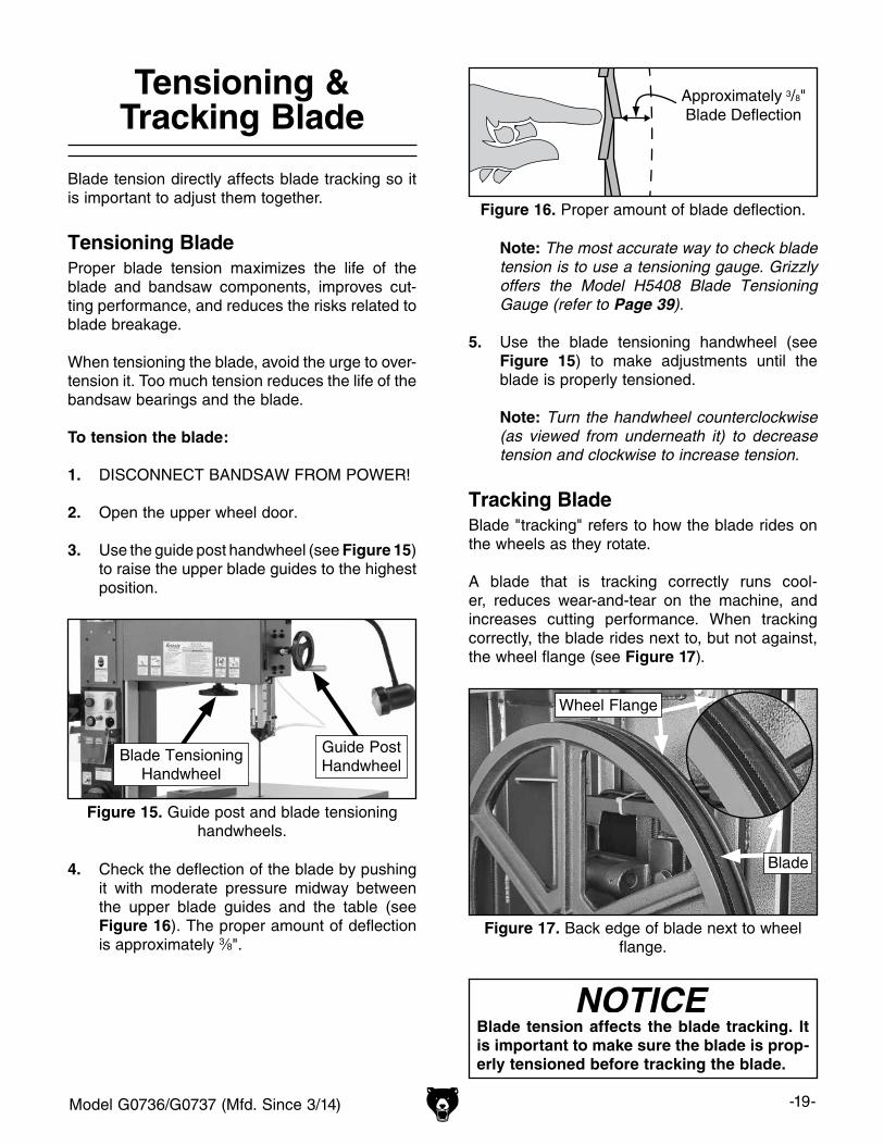
3. Use the guide post handwheel (see Figure 15) to raise the upper blade guides to the highest position.
Approximately 3/8"Blade Deflection
Figure 16. Proper amount of blade deflection.
4. Check the deflection of the blade by pushing it with moderate pressure midway between the upper blade guides and the table (see Figure 16). The proper amount of deflection is approximately 3⁄8".
Note: The most accurate way to check blade tension is to use a tensioning gauge. Grizzly offers the Model H5408 Blade Tensioning Gauge (refer to Page 39).
5. Use the blade tensioning handwheel (see Figure 15) to make adjustments until the blade is properly tensioned.
Note: Turn the handwheel counterclockwise (as viewed from underneath it) to decrease tension and clockwise to increase tension.
Tracking BladeBlade "tracking" refers to how the blade rides on the wheels as they rotate.
A blade that is tracking correctly runs cool-er, reduces wear-and-tear on the machine, and increases cutting performance. When tracking correctly, the blade rides next to, but not against, the wheel flange (see Figure 17).
Blade tension affects the blade tracking. It is important to make sure the blade is prop-erly tensioned before tracking the blade.
Figure 15. Guide post and blade tensioning handwheels.
Blade TensioningHandwheel
Guide PostHandwheel
Figure 17. Back edge of blade next to wheel flange.
Blade
Wheel Flange
-20- Model G0736/G0737 (Mfd. Since 3/14)
5. Open the upper wheel door.
6. Watch the position of the blade on the wheel as you rotate the upper wheel by hand sev-eral times.
— If the blade rides up against the wheel flange without pressure and does not wan-der, then no further adjustments are need-ed. Skip ahead to Step 9.
— If the blade does not ride up next to the wheel flange or it wanders, proceed with the next step.
7. Turn the tracking knob a small amount, then rotate the upper wheel by hand several times while watching the blade position on the wheel
Note: Turn the knob clockwise to make the blade move toward the wheel flange, and counterclockwise to move away from the wheel flange.
8. Repeat Step 7 until the blade rides evenly next to the wheel flange without pressure and without wandering across the wheel.
9. Re-install the V-belt and secure both doors.
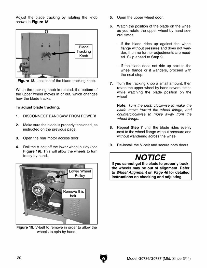
Adjust the blade tracking by rotating the knob shown in Figure 18.
If you cannot get the blade to properly track, the wheels may be out of alignment. Refer to Wheel Alignment on Page 46 for detailed instructions on checking and adjusting.
When the tracking knob is rotated, the bottom of the upper wheel moves in or out, which changes how the blade tracks.
To adjust blade tracking:
1. DISCONNECT BANDSAW FROM POWER!
2. Make sure the blade is properly tensioned, as instructed on the previous page.
3. Open the rear motor access door.
4. Roll the V-belt off the lower wheel pulley (see Figure 19). This will allow the wheels to turn freely by hand.
Figure 18. Location of the blade tracking knob.
Blade Tracking
Knob
Figure 19. V-belt to remove in order to allow the wheels to spin by hand.
Lower WheelPulley
Remove thisbelt.
Model G0736/G0737 (Mfd. Since 3/14) -21-
Adjusting Blade Guide Assemblies
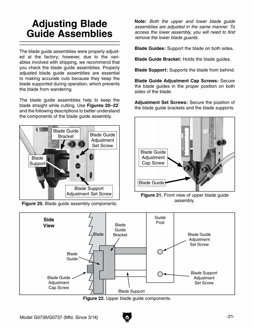
The blade guide assemblies were properly adjust-ed at the factory; however, due to the vari-ables involved with shipping, we recommend that you check the blade guide assemblies. Properly adjusted blade guide assemblies are essential to making accurate cuts because they keep the blade supported during operation, which prevents the blade from wandering.
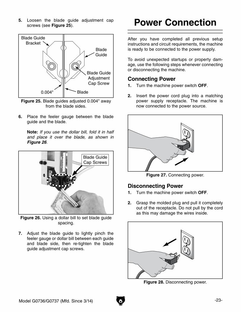
The blade guide assemblies help to keep the blade straight while cutting. Use Figures 20–22` and the following descriptions to better understand the components of the blade guide assembly.
Blade Support
BladeGuide
Blade GuideAdjustmentCap Screw
SideView Blade
GuideBracket
GuidePost
Blade GuideAdjustmentSet Screw
Blade SupportAdjustmentSet Screw
Blade
Figure 22. Upper blade guide components.
Note: Both the upper and lower blade guide assemblies are adjusted in the same manner. To access the lower assembly, you will need to first remove the lower blade guards.
Blade Guides: Support the blade on both sides.
Blade Guide Bracket: Holds the blade guides.
Blade Support: Supports the blade from behind.
Blade Guide Adjustment Cap Screws: Secure the blade guides in the proper position on both sides of the blade.
Adjustment Set Screws: Secure the position of the blade guide brackets and the blade supports.
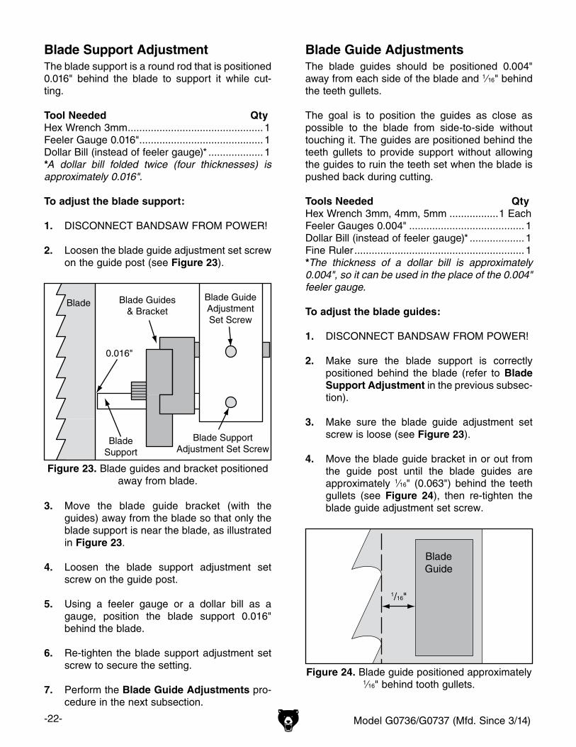
Figure 21. Front view of upper blade guide assembly.
Blade Guide
Blade GuideAdjustmentCap Screw
Figure 20. Blade guide assembly components.
Blade GuideBracket
Blade Support
Blade GuideAdjustmentSet Screw
Blade SupportAdjustment Set Screw
-22- Model G0736/G0737 (Mfd. Since 3/14)
Blade Support AdjustmentThe blade support is a round rod that is positioned 0.016" behind the blade to support it while cut-ting.
Tool Needed QtyHex Wrench 3mm ............................................... 1Feeler Gauge 0.016" ........................................... 1Dollar Bill (instead of feeler gauge)* ................... 1*A dollar bill folded twice (four thicknesses) is approximately 0.016".
To adjust the blade support:
1. DISCONNECT BANDSAW FROM POWER!
2. Loosen the blade guide adjustment set screw on the guide post (see Figure 23).
BladeGuide
1/16"
Figure 24. Blade guide positioned approximately 1⁄16" behind tooth gullets.
Blade Guide AdjustmentsThe blade guides should be positioned 0.004" away from each side of the blade and 1⁄16" behind the teeth gullets.
The goal is to position the guides as close as possible to the blade from side-to-side without touching it. The guides are positioned behind the teeth gullets to provide support without allowing the guides to ruin the teeth set when the blade is pushed back during cutting.
Tools Needed QtyHex Wrench 3mm, 4mm, 5mm .................1 EachFeeler Gauges 0.004" ........................................ 1 Dollar Bill (instead of feeler gauge)* ................... 1Fine Ruler ........................................................... 1*The thickness of a dollar bill is approximately 0.004", so it can be used in the place of the 0.004" feeler gauge.
To adjust the blade guides:
1. DISCONNECT BANDSAW FROM POWER!
2. Make sure the blade support is correctly positioned behind the blade (refer to Blade Support Adjustment in the previous subsec-tion).
3. Make sure the blade guide adjustment set screw is loose (see Figure 23).
4. Move the blade guide bracket in or out from the guide post until the blade guides are approximately 1⁄16" (0.063") behind the teeth gullets (see Figure 24), then re-tighten the blade guide adjustment set screw.
BladeSupport
Blade Guides& Bracket
0.016"
BladeBlade GuideAdjustmentSet Screw
Blade SupportAdjustment Set Screw
Figure 23. Blade guides and bracket positioned away from blade.
3. Move the blade guide bracket (with the guides) away from the blade so that only the blade support is near the blade, as illustrated in Figure 23.
4. Loosen the blade support adjustment set screw on the guide post.
5. Using a feeler gauge or a dollar bill as a gauge, position the blade support 0.016" behind the blade.
6. Re-tighten the blade support adjustment set screw to secure the setting.
7. Perform the Blade Guide Adjustments pro-cedure in the next subsection.
Model G0736/G0737 (Mfd. Since 3/14) -23-
5. Loosen the blade guide adjustment cap screws (see Figure 25).
6. Place the feeler gauge between the blade guide and the blade.
Note: If you use the dollar bill, fold it in half and place it over the blade, as shown in Figure 26.
7. Adjust the blade guide to lightly pinch the feeler gauge or dollar bill between each guide and blade side, then re-tighten the blade guide adjustment cap screws.
BladeGuide
Blade GuideBracket
Blade GuideAdjustmentCap Screw
Blade0.004"
Figure 25. Blade guides adjusted 0.004" away from the blade sides.
Figure 26. Using a dollar bill to set blade guide spacing.
Blade GuideCap Screws
Power Connection
After you have completed all previous setup instructions and circuit requirements, the machine is ready to be connected to the power supply.
To avoid unexpected startups or property dam-age, use the following steps whenever connecting or disconnecting the machine.
Connecting Power
Figure 27. Connecting power.
1. TurnthemachinepowerswitchOFF.
2. Insert the power cord plug into a matchingpower supply receptacle. The machine isnowconnectedtothepowersource.
Disconnecting Power
Figure 28. Disconnecting power.
1. TurnthemachinepowerswitchOFF.
2. Graspthemoldedplugandpullitcompletelyoutofthereceptacle.Donotpullbythecordasthismaydamagethewiresinside.
-24- Model G0736/G0737 (Mfd. Since 3/14)
Test Run
Once the assembly is complete, test run your machine to make sure it runs properly and is ready for regular operation. The test run consists of verifying the following: 1) The motor powers up and runs correctly and 2) the STOP button safety feature works correctly.
If, during the test run, you cannot easily locate the source of an unusual noise or vibration, stop using the machine immediately, then review Troubleshooting on Page 44.
If you cannot find a remedy, contact our Tech Support at (570) 546-9663 for assistance.
To test run the machine:
1. Make sure you understand the safety instruc-tions at the beginning of the manual and that the machine is setup properly.
2. Make sure all tools and objects used during setup are cleared away from the machine.
3. Push the bandsaw STOP button in, then twist it clockwise so it pops out. When the STOP button pops out, the switch is reset and ready for operation (see Figure 29).
Figure 29. Resetting the STOP button.
4. Make sure the blade is properly tensioned and tracked (refer to Tensioning & Tracking Blade on Page 19) and the blade guides are positioned correctly (refer to Adjusting Blade Guide Assemblies on Page 21).
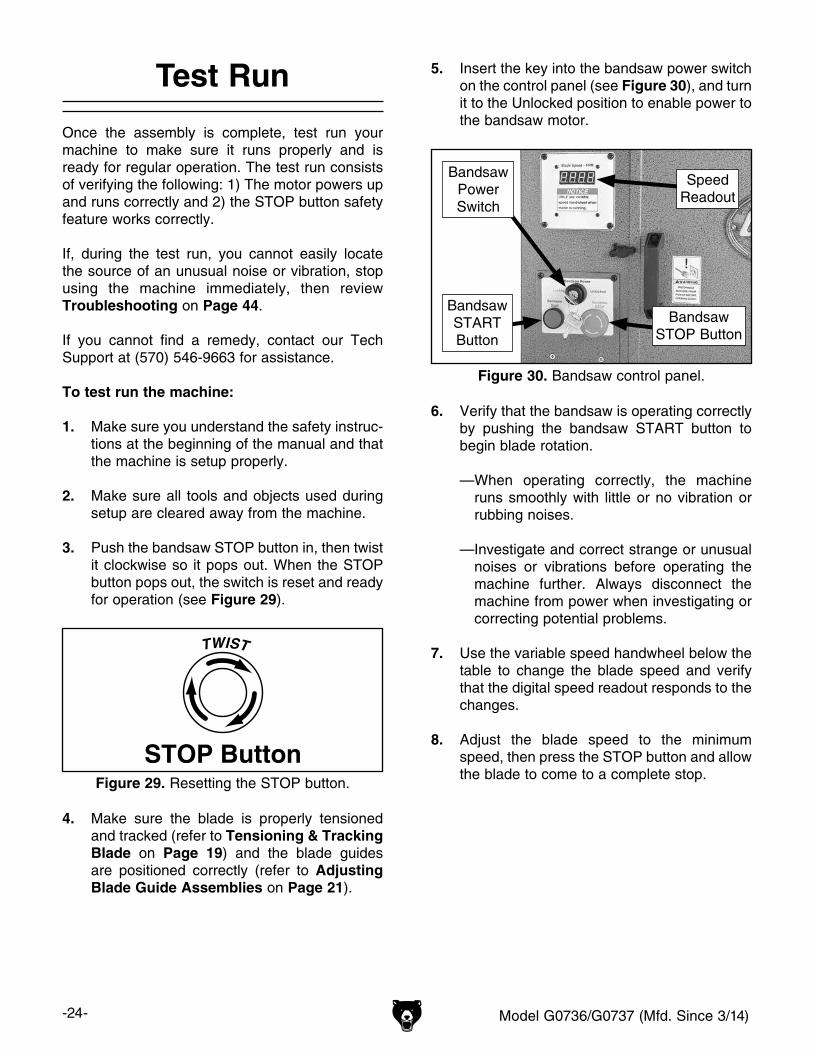
5. Insert the key into the bandsaw power switch on the control panel (see Figure 30), and turn it to the Unlocked position to enable power to the bandsaw motor.
6. Verify that the bandsaw is operating correctly by pushing the bandsaw START button to begin blade rotation.
—When operating correctly, the machine runs smoothly with little or no vibration or rubbing noises.
— Investigate and correct strange or unusual noises or vibrations before operating the machine further. Always disconnect the machine from power when investigating or correcting potential problems.
7. Use the variable speed handwheel below the table to change the blade speed and verify that the digital speed readout responds to the changes.
8. Adjust the blade speed to the minimum speed, then press the STOP button and allow the blade to come to a complete stop.
Figure 30. Bandsaw control panel.
BandsawSTOP Button
SpeedReadout
BandsawPowerSwitch
BandsawSTARTButton
Model G0736/G0737 (Mfd. Since 3/14) -25-
9. WITHOUT resetting the STOP button, press the bandsaw START button. The machine should not start.
—If the machine does start (with the STOP button pushed in), immediately disconnect power to the machine. The STOP button safety feature is not working correctly. This safety feature must work properly before proceeding with regular operations. Call Tech Support for help.
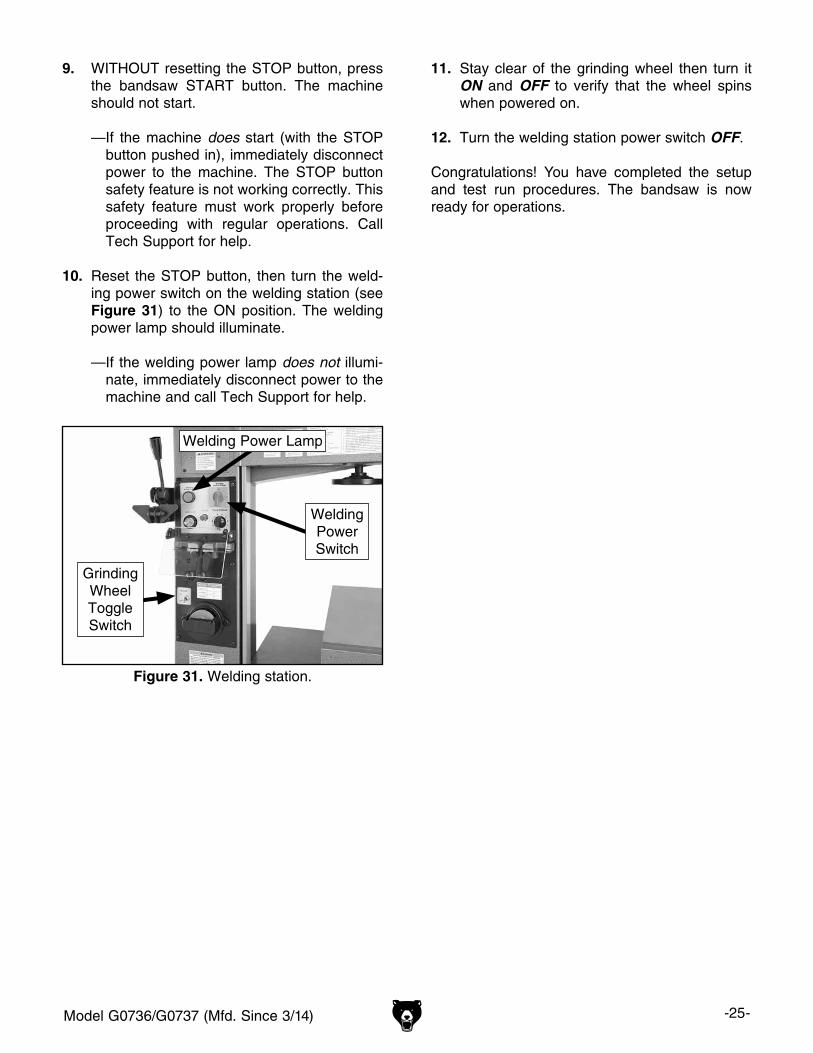
10. Reset the STOP button, then turn the weld-ing power switch on the welding station (see Figure 31) to the ON position. The welding power lamp should illuminate.
—If the welding power lamp does not illumi-nate, immediately disconnect power to the machine and call Tech Support for help.
11. Stay clear of the grinding wheel then turn it ON and OFF to verify that the wheel spins when powered on.
12. Turn the welding station power switch OFF.
Congratulations! You have completed the setup and test run procedures. The bandsaw is now ready for operations.
Figure 31. Welding station.
WeldingPowerSwitch
Welding Power Lamp
GrindingWheelToggleSwitch
-26- Model G0736/G0737 (Mfd. Since 3/14)
SECTION 4: OPERATIONS
Operation Overview
The purpose of this overview is to provide the nov-ice machine operator with a basic understanding of how the machine is used during operation, so the machine controls/components discussed later in this manual are easier to understand.
Due to the generic nature of this overview, it is not intended to be an instructional guide. To learn more about specific operations, read this entire manual and seek additional training from expe-rienced machine operators, and do additional research outside of this manual by reading "how-to" books, trade magazines, or websites.
To complete a typical operation, the operator does the following:
1. Examines the workpiece to make sure it is suitable for cutting, and that it can be posi-tioned in a stable manner on the table.
2. Adjusts the table tilt, if necessary, to the cor-rect angle of the desired cut.
3. Adjusts the height of the upper blade guides approximately 1⁄8"–1⁄4" higher than the thick-ness of the workpiece.
4. Adjusts the fence to the desired width of cut then locks it in place.
5. Checks the outfeed side of the machine for proper support and to make sure the workpiece can safely pass all the way through the blade without interference.
6. Puts on safety glasses and a face shield, and starts the bandsaw.
7. If necessary, uses push sticks or jigs for small or narrow workpieces to keep fingers away from the blade.
8. Feeds the workpiece all the way through the blade while maintaining firm pressure on the workpiece against the table and fence. Keeps hands and fingers out of the blade path and away from the blade during the entire cut.
9. Stops the machine.
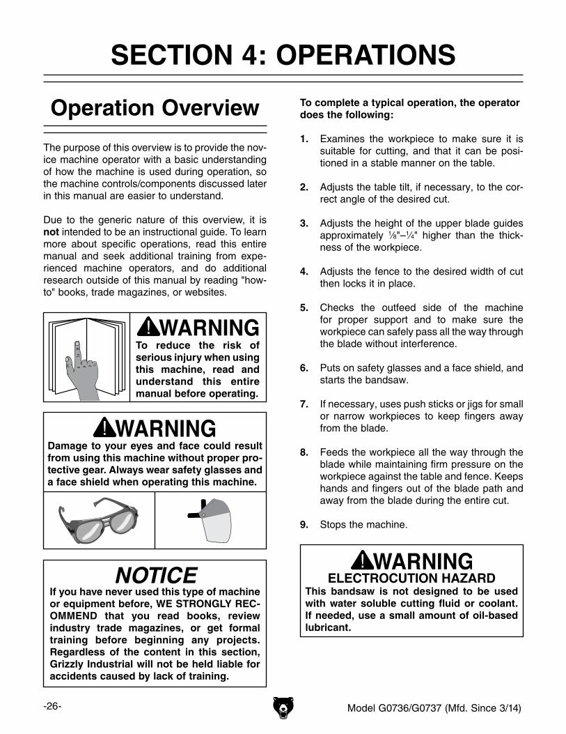
Damage to your eyes and face could result from using this machine without proper pro-tective gear. Always wear safety glasses and a face shield when operating this machine.
To reduce the risk of serious injury when using this machine, read and understand this entire manual before operating.
NOTICEIf you have never used this type of machine or equipment before, WE STRONGLY REC-OMMEND that you read books, review industry trade magazines, or get formal training before beginning any projects. Regardless of the content in this section, Grizzly Industrial will not be held liable for accidents caused by lack of training.
ELECTROCUTION HAZARDThis bandsaw is not designed to be used with water soluble cutting fluid or coolant. If needed, use a small amount of oil-based lubricant.
Model G0736/G0737 (Mfd. Since 3/14) -27-
Disabling & Locking Bandsaw Power
Switch
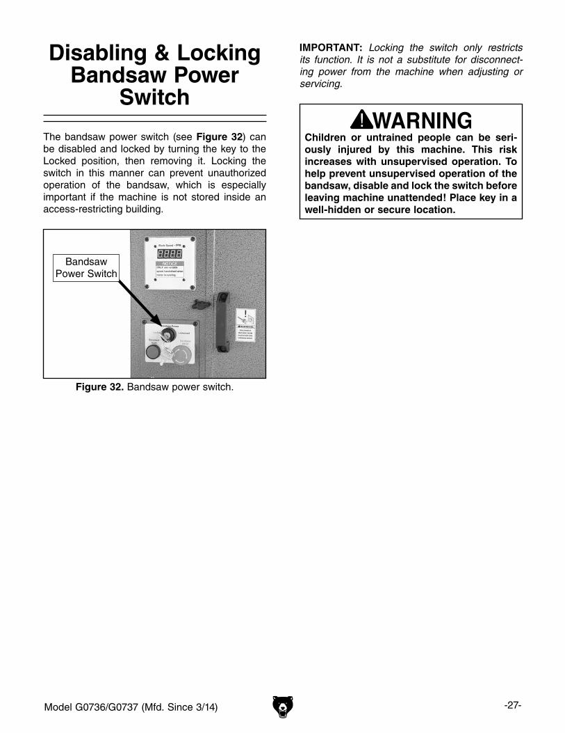
The bandsaw power switch (see Figure 32) can be disabled and locked by turning the key to the Locked position, then removing it. Locking the switch in this manner can prevent unauthorized operation of the bandsaw, which is especially important if the machine is not stored inside an access-restricting building.
Figure 32. Bandsaw power switch.
BandsawPower Switch
Children or untrained people can be seri-ously injured by this machine. This risk increases with unsupervised operation. To help prevent unsupervised operation of the bandsaw, disable and lock the switch before leaving machine unattended! Place key in a well-hidden or secure location.
IMPORTANT: Locking the switch only restricts its function. It is not a substitute for disconnect-ing power from the machine when adjusting or servicing.
-28- Model G0736/G0737 (Mfd. Since 3/14)
Adjusting Table Tilt
To perform beveled cuts, the bandsaw table tilts 15° side to side, and 10° front to back.
Tools Needed QtyHex Wrench 10mm ............................................. 1Wrench or Socket 17mm .................................... 1
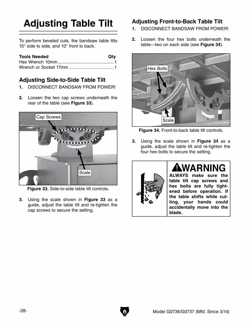
Adjusting Side-to-Side Table Tilt1. DISCONNECT BANDSAW FROM POWER!
2. Loosen the two cap screws underneath the rear of the table (see Figure 33).
3. Using the scale shown in Figure 33 as a guide, adjust the table tilt and re-tighten the cap screws to secure the setting.
ALWAYS make sure the table tilt cap screws and hex bolts are fully tight-ened before operation. If the table shifts while cut-ting, your hands could accidentally move into the blade.
Figure 33. Side-to-side table tilt controls.
Scale
Cap Screws
Adjusting Front-to-Back Table Tilt1. DISCONNECT BANDSAW FROM POWER!
2. Loosen the four hex bolts underneath the table—two on each side (see Figure 34).
3. Using the scale shown in Figure 34 as a guide, adjust the table tilt and re-tighten the four hex bolts to secure the setting.
Figure 34. Front-to-back table tilt controls.
Hex Bolts
Scale

Model G0736/G0737 (Mfd. Since 3/14) -29-
Blade Selection
Selecting the right blade for the cut requires a knowledge of various blade characteristics.
Blade Terminology
A. Kerf: The amount of material removed by the blade during cutting.
B. Tooth Set: The amount each tooth is bent left or right from the blade.
C. Gauge: The thickness of the blade.
D. Blade Width: The widest point of the blade measured from the tip of the tooth to the back edge of the blade.
E. Tooth Rake: The angle of the tooth face from a line perpendicular to the length of the blade.
F. Gullet Depth: The distance from the tooth tip to the bottom of the curved area (gullet).
G. Tooth Pitch: The distance between tooth tips.
H. Blade Back: The distance between the bot-tom of the gullet and the back edge of the blade.
I. TPI: The number of teeth per inch measured from gullet to gullet.
Figure 35. Bandsaw blade terminology.
G
B
C
DE
F H
I
A
Blade LengthMeasured by the blade circumference, blade lengths are usually unique to the brand of your bandsaw and the distance between the wheels.
Model Blade LengthG0736 ............................................................120"G0737 ............................................................140"
Blade WidthMeasured from the back of the blade to the tip of the blade tooth (the widest point), blade width is often the first consideration given to blade selec-tion. Blade width dictates the largest and smallest curve that can be cut, as well as how accurately it can cut a straight line—generally the wider the blade, the straighter it will cut.
The blade width range for this bandsaw is 1⁄8"– 5⁄8".
Always pick the blade width that best suits your operation.
Curve Cutting: Use the chart below as a guide when choosing the correct blade for curve cutting. Determine the smallest radius curve that will be cut on your workpiece and use the corresponding blade width.
Minimum Radius of Cut Blade Width1⁄8" 1⁄8"3⁄8" 3⁄16"5⁄8" 1⁄4"
1 1⁄4" 3⁄8"
2 1⁄2" 1⁄2"
3 3⁄4" 5⁄8"
Workpieces that cannot be supported or stabilized without a vise or jig should not be cut on a vertical metal-cutting bandsaw, because they can unexpectedly move while cutting and draw the operator's hands into the moving blade causing lacerations or amputation. Examples are chains, cables, round or oblong-shaped workpieces, workpieces with internal or built-in moving or rotations parts, etc.
-30- Model G0736/G0737 (Mfd. Since 3/14)
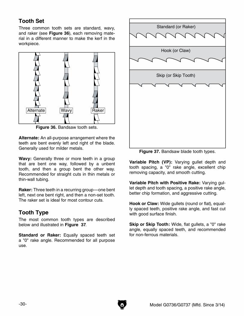
Tooth SetThree common tooth sets are standard, wavy, and raker (see Figure 36), each removing mate-rial in a different manner to make the kerf in the workpiece.
Alternate: An all-purpose arrangement where the teeth are bent evenly left and right of the blade. Generally used for milder metals.
Wavy: Generally three or more teeth in a group that are bent one way, followed by a unbent tooth, and then a group bent the other way. Recommended for straight cuts in thin metals or thin-wall tubing.
Raker: Three teeth in a recurring group—one bent left, next one bent right, and then a non-set tooth. The raker set is ideal for most contour cuts.
Tooth TypeThe most common tooth types are described below and illustrated in Figure 37.
Standard or Raker: Equally spaced teeth set a "0" rake angle. Recommended for all purpose use.
Figure 36. Bandsaw tooth sets.
Alternate Wavy Raker
Standard (or Raker)
Hook (or Claw)
Skip (or Skip Tooth)
Figure 37. Bandsaw blade tooth types.
Variable Pitch (VP): Varying gullet depth and tooth spacing, a "0" rake angle, excellent chip removing capacity, and smooth cutting.
Variable Pitch with Positive Rake: Varying gul-let depth and tooth spacing, a positive rake angle, better chip formation, and aggressive cutting.
Hook or Claw: Wide gullets (round or flat), equal-ly spaced teeth, positive rake angle, and fast cut with good surface finish.
Skip or Skip Tooth: Wide, flat gullets, a "0" rake angle, equally spaced teeth, and recommended for non-ferrous materials.
Model G0736/G0737 (Mfd. Since 3/14) -31-
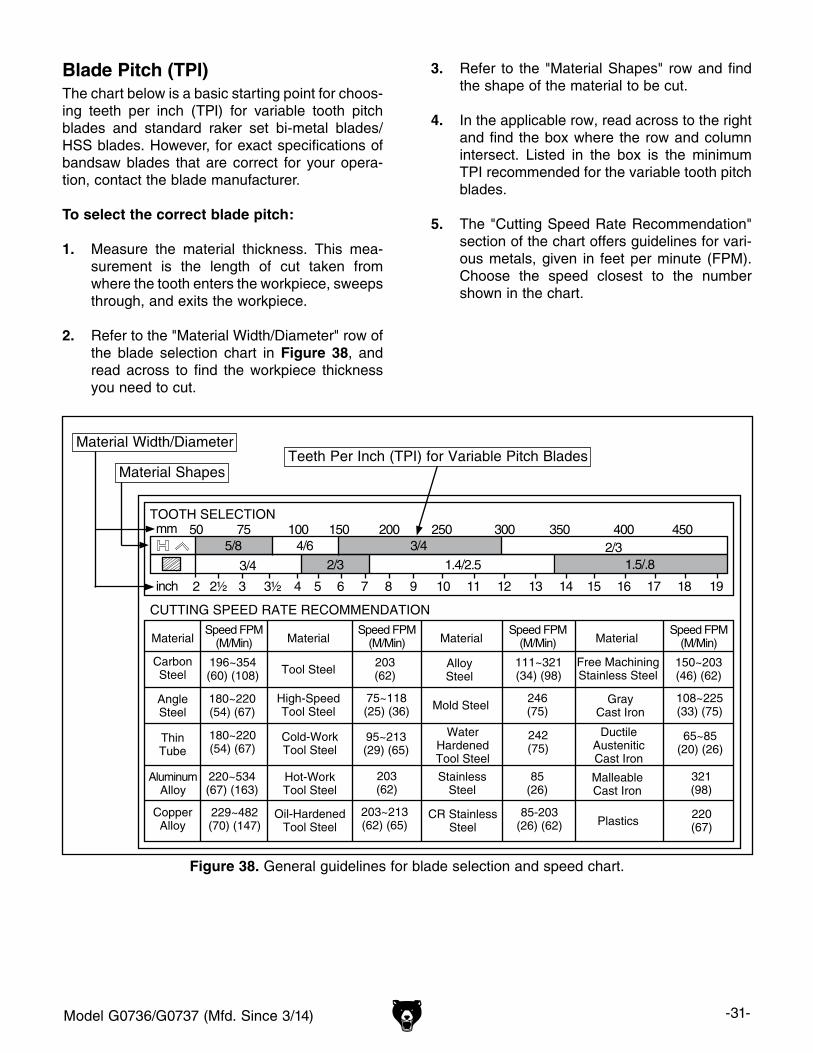
Blade Pitch (TPI)The chart below is a basic starting point for choos-ing teeth per inch (TPI) for variable tooth pitch blades and standard raker set bi-metal blades/HSS blades. However, for exact specifications of bandsaw blades that are correct for your opera-tion, contact the blade manufacturer.
To select the correct blade pitch:
1. Measure the material thickness. This mea-surement is the length of cut taken from where the tooth enters the workpiece, sweeps through, and exits the workpiece.
2. Refer to the "Material Width/Diameter" row of the blade selection chart in Figure 38, and read across to find the workpiece thickness you need to cut.
CUTTING SPEED RATE RECOMMENDATION
TOOTH SELECTION50
2 3 4 5 6 7 8 9 10 11 12 13 14 15 16 17 18 192½ 3½
75 100 150 200 250 300 350 4002/3
2/3 1.4/2.5 1.5/.83/4
3/4
4/65/8450mm
inch
CopperAlloy
229~482(70) (147)
203~213(62) (65)
85-203(26) (62)
220(67)
220~534(67) (163)
203(62)
85(26)
321(98)
180~220(54) (67)
95~213(29) (65)
242(75)
65~85(20) (26)
180~220(54) (67)
75~118(25) (36)
246(75)
108~225(33) (75)
196~354(60) (108)
203(62)
111~321(34) (98)
150~203(46) (62)
AluminumAlloy
ThinTube
AngleSteel
CarbonSteel
Speed FPM(M/Min)
Speed FPM(M/Min)
Speed FPM(M/Min)
Speed FPM(M/Min)Material Material Material Material
Tool Steel
Mold SteelHigh-SpeedTool Steel
AlloySteel
WaterHardenedTool Steel
StainlessSteel
CR StainlessSteel
Free MachiningStainless Steel
GrayCast Iron
DuctileAusteniticCast Iron
MalleableCast Iron
Plastics
Cold-WorkTool Steel
Hot-WorkTool Steel
Oil-HardenedTool Steel
Material Width/Diameter
Material ShapesTeeth Per Inch (TPI) for Variable Pitch Blades
Figure 38. General guidelines for blade selection and speed chart.
3. Refer to the "Material Shapes" row and find the shape of the material to be cut.
4. In the applicable row, read across to the right and find the box where the row and column intersect. Listed in the box is the minimum TPI recommended for the variable tooth pitch blades.
5. The "Cutting Speed Rate Recommendation" section of the chart offers guidelines for vari-ous metals, given in feet per minute (FPM). Choose the speed closest to the number shown in the chart.
-32- Model G0736/G0737 (Mfd. Since 3/14)
Blade CareA bandsaw blade is a thin piece of steel that is subjected to tremendous strain. You can obtain longer use from a bandsaw blade if you give it fair treatment and always use the appropriate feed rate for your operation.
Be sure to select blades with the proper width, set, type, and pitch for each application. Using the wrong blade will produce unnecessary heat and shorten the life of the blade.
A clean blade will perform much better than a dirty blade. Dirty or gummed up blades pass through the cutting material with much more resistance than clean blades. This extra resistance also causes unnecessary heat.
Blade Break-InThe sharp teeth tips and edges of a new blade are extremely sharp, and cutting at too fast of a feed rate fractures the beveled edges of the teeth and causes premature blade wear.
To properly break-in a new blade:
1. Choose the correct speed for the blade and material of the operation.
2. Reduce the feed pressure by half for the first 50–100 in2 of material cut.
3. To avoid twisting the blade when cutting, adjust the feed pressure when the total width of the blade is in the cut.
4. Use the Chip Inspection Chart on the next page to check the blade efficiency.
Blade Breakage
Many conditions may cause a bandsaw blade to break. Blade breakage is unavoidable, in some cases, since it is the natural result of the peculiar stresses that bandsaw blades must endure.
Blade breakage is also due to avoidable circum-stances. Avoidable blade breakage is most often the result of poor care or judgement on the part of the operator when mounting or adjusting the blade or support guides.
The most common causes of blade breakage are:
• Faulty alignment or adjustment of the blade guides.
• Forcing or twisting a wide blade around a short radius.
• Feeding the workpiece too fast.
• Dull or damaged teeth.
• Over-tensioned blade.
• Top blade guide assembly set too high above the workpiece. Adjust the top blade guide assembly so that there is approximately 1⁄8"–1⁄4" between the bottom of the assembly and the workpiece.
• Using a blade with a lumpy or improperly fin-ished braze or weld.
• Continuously running the bandsaw when not in use.
• Leaving the blade tensioned when not in use.
• Using the wrong pitch (TPI) for the workpiece thickness. The general rule of thumb is to have not less than two teeth in contact with the workpiece at all times during cutting.
Blade Care & Break-In

Model G0736/G0737 (Mfd. Since 3/14) -33-
Chip Inspection Chart
The best method of evaluating the performance of your cutting operation is to inspect the chips that are formed. Refer to the chart below for chip inspection guidelines.
ChipAppearance
ChipDescription
ChipColor
BladeSpeed
FeedPressure
AdditionalActions
Thin & Curled Silver Good Good
Hard, Thick & Short
Brown or Blue Decrease DecreaseCheck Cutting
Fluid Mix
Hard, Strong & Thick
Brown or Blue Decrease DecreaseCheck Cutting
Fluid Mix
Hard, Strong & Thick
Silver or Light Brown
Good Decrease Slightly
Check Blade Pitch
Hard & Thin Silver Increase DecreaseCheck Blade
Pitch
Straight & Thin Silver Good Increase
Powdery Silver Decrease Increase
Curled Tight & Thin
Silver Good DecreaseCheck Blade
Pitch
thin & curled
short, hard & thick
thick, hard & strong
thick, hard & strong
thin & straight
powdery
thin & curled tightly
hard & thin
thin & curled
short, hard & thick
thick, hard & strong
thick, hard & strong
thin & straight
powdery
thin & curled tightly
hard & thin
thin & curled
short, hard & thick
thick, hard & strong
thick, hard & strong
thin & straight
powdery
thin & curled tightly
hard & thin
thin & curled
short, hard & thick
thick, hard & strong
thick, hard & strong
thin & straight
powdery
thin & curled tightly
hard & thin
thin & curled
short, hard & thick
thick, hard & strong
thick, hard & strong
thin & straight
powdery
thin & curled tightly
hard & thin
thin & curled
short, hard & thick
thick, hard & strong
thick, hard & strong
thin & straight
powdery
thin & curled tightly
hard & thin
thin & curled
short, hard & thick
thick, hard & strong
thick, hard & strong
thin & straight
powdery
thin & curled tightly
hard & thin
thin & curled
short, hard & thick
thick, hard & strong
thick, hard & strong
thin & straight
powdery
thin & curled tightly
hard & thin
Figure 39. Chip inspection chart.
-34- Model G0736/G0737 (Mfd. Since 3/14)
Blade Changes
To replace the blade:
1. DISCONNECT BANDSAW FROM POWER!
2. Open the upper and lower wheel doors.
3. Release blade tension by rotating the tension-ing handwheel counterclockwise (as viewed from underneath).
4. Put on heavy gloves.
5. Remove the .
6. Slide the blade off the upper and lower wheels, then through the blade guards and table slit.
7. In reverse order from above, position the new blade so that the teeth are facing downward and forward, then slide it through the table slot and onto the wheels.
Note: If the teeth will not face downward in any orientation, the blade is inside-out. Carefully twist the blade right side-out.
All saw blades are danger-ous and may cause per-sonal injury. To reduce the risk of being injured, wear leather gloves when han-dling saw blades.
Make sure that the table pin is installed before beginning operations. The table pin prevents the front table halves from get-ting misaligned when heavy workpieces are loaded on the table.
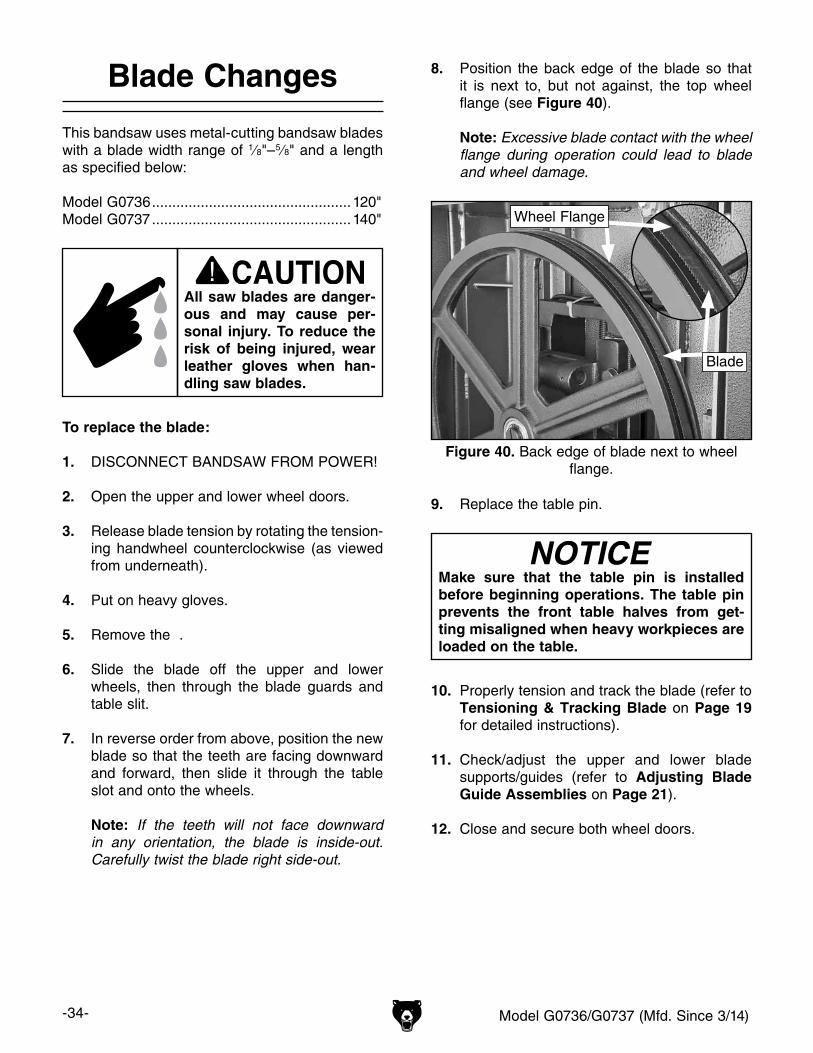
8. Position the back edge of the blade so that it is next to, but not against, the top wheel flange (see Figure 40).
Note: Excessive blade contact with the wheel flange during operation could lead to blade and wheel damage.
10. Properly tension and track the blade (refer to Tensioning & Tracking Blade on Page 19 for detailed instructions).
11. Check/adjust the upper and lower blade supports/guides (refer to Adjusting Blade Guide Assemblies on Page 21).
12. Close and secure both wheel doors.
Figure 40. Back edge of blade next to wheel flange.
Blade
Wheel Flange
This bandsaw uses metal-cutting bandsaw blades with a blade width range of 1⁄8"– 5⁄8" and a length as specified below:
Model G0736 .................................................120"Model G0737 .................................................140"
9. Replace the table pin.
Model G0736/G0737 (Mfd. Since 3/14) -35-
Guide Post
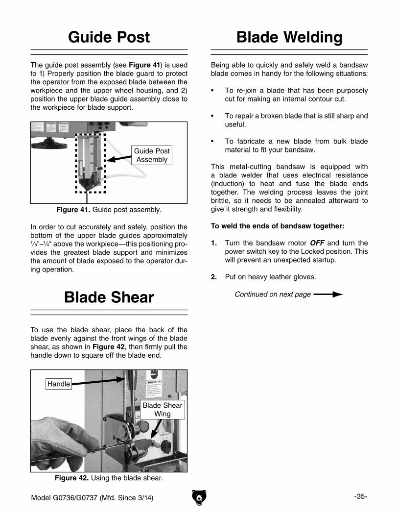
The guide post assembly (see Figure 41) is used to 1) Properly position the blade guard to protect the operator from the exposed blade between the workpiece and the upper wheel housing, and 2) position the upper blade guide assembly close to the workpiece for blade support.
Blade Welding
Being able to quickly and safely weld a bandsaw blade comes in handy for the following situations:
• To re-join a blade that has been purposely cut for making an internal contour cut.
• To repair a broken blade that is still sharp and useful.
• To fabricate a new blade from bulk blade material to fit your bandsaw.
This metal-cutting bandsaw is equipped with a blade welder that uses electrical resistance (induction) to heat and fuse the blade ends together. The welding process leaves the joint brittle, so it needs to be annealed afterward to give it strength and flexibility.
To weld the ends of bandsaw together:
1. Turn the bandsaw motor OFF and turn the power switch key to the Locked position. This will prevent an unexpected startup.
2. Put on heavy leather gloves.
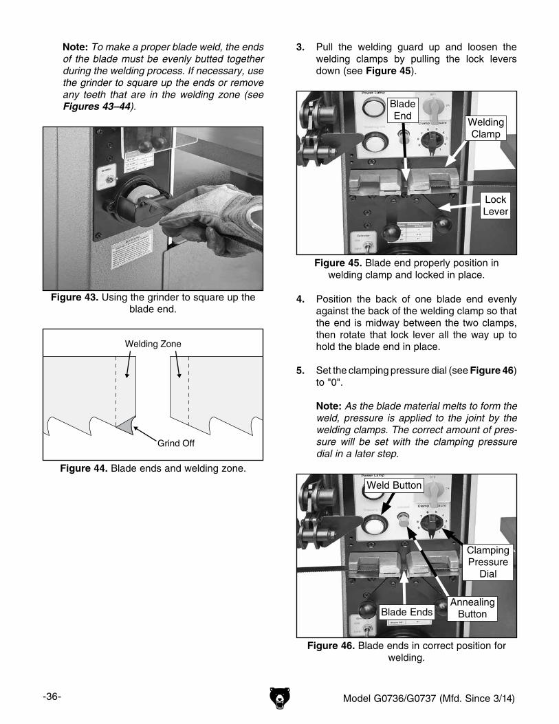
Figure 42. Using the blade shear.
Blade ShearWing
Handle
In order to cut accurately and safely, position the bottom of the upper blade guides approximately 1⁄8"–1⁄4" above the workpiece—this positioning pro-vides the greatest blade support and minimizes the amount of blade exposed to the operator dur-ing operation.
Figure 41. Guide post assembly.
Guide PostAssembly
Blade Shear
To use the blade shear, place the back of the blade evenly against the front wings of the blade shear, as shown in Figure 42, then firmly pull the handle down to square off the blade end.
-36- Model G0736/G0737 (Mfd. Since 3/14)
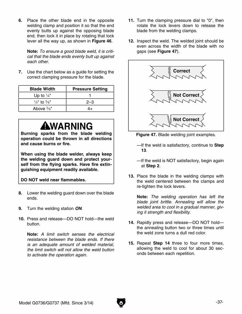
Note: To make a proper blade weld, the ends of the blade must be evenly butted together during the welding process. If necessary, use the grinder to square up the ends or remove any teeth that are in the welding zone (see Figures 43–44).
Figure 43. Using the grinder to square up the blade end.
Welding Zone
Grind Off
Figure 44. Blade ends and welding zone.
3. Pull the welding guard up and loosen the welding clamps by pulling the lock levers down (see Figure 45).
4. Position the back of one blade end evenly against the back of the welding clamp so that the end is midway between the two clamps, then rotate that lock lever all the way up to hold the blade end in place.
5. Set the clamping pressure dial (see Figure 46) to "0".
Note: As the blade material melts to form the weld, pressure is applied to the joint by the welding clamps. The correct amount of pres-sure will be set with the clamping pressure dial in a later step.
Figure 45. Blade end properly position in welding clamp and locked in place.
WeldingClamp
BladeEnd
LockLever
Figure 46. Blade ends in correct position for welding.
ClampingPressure
Dial
AnnealingButtonBlade Ends
Weld Button
Model G0736/G0737 (Mfd. Since 3/14) -37-
6. Place the other blade end in the opposite welding clamp and position it so that the end evenly butts up against the opposing blade end, then lock it in place by rotating that lock lever all the way up, as shown in Figure 46.
Note: To ensure a good blade weld, it is criti-cal that the blade ends evenly butt up against each other.
7. Use the chart below as a guide for setting the correct clamping pressure for the blade.
Blade Width Pressure Setting
Up to 1⁄4" 11⁄4" to 3⁄8" 2–3
Above 3⁄8" 4+
8. Lower the welding guard down over the blade ends.
9. Turn the welding station ON.
10. Press and release—DO NOT hold—the weld button.
Note: A limit switch senses the electrical resistance between the blade ends. If there is an adequate amount of welded material, the limit switch will not allow the weld button to activate the operation again.
Burning sparks from the blade welding operation could be thrown in all directions and cause burns or fire.
When using the blade welder, always keep the welding guard down and protect your-self from the flying sparks. Have fire extin-guishing equipment readily available.
DO NOT weld near flammables.
11. Turn the clamping pressure dial to "0", then rotate the lock levers down to release the blade from the welding clamps.
12. Inspect the weld. The welded joint should be even across the width of the blade with no gaps (see Figure 47).
Correct
Not Correct
Not Correct
Correct
Not Correct
Figure 47. Blade welding joint examples.
— If the weld is satisfactory, continue to Step 13.
— If the weld is NOT satisfactory, begin again at Step 2.
13. Place the blade in the welding clamps with the weld centered between the clamps and re-tighten the lock levers.
Note: The welding operation has left the blade joint brittle. Annealing will allow the welded area to cool in a gradual manner, giv-ing it strength and flexibility.
14. Rapidly press and release—DO NOT hold—the annealing button two or three times until the weld zone turns a dull red color.
15. Repeat Step 14 three to four more times, allowing the weld to cool for about 30 sec-onds between each repetition.
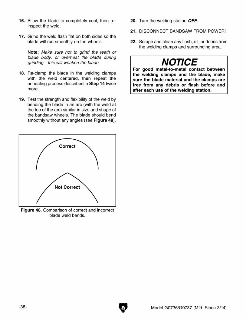
-38- Model G0736/G0737 (Mfd. Since 3/14)
Correct
Not Correct
Not Correct
Correct
Not Correct
Figure 48. Comparison of correct and incorrect blade weld bends.
16. Allow the blade to completely cool, then re-inspect the weld.
17. Grind the weld flash flat on both sides so the blade will run smoothly on the wheels.
Note: Make sure not to grind the teeth or blade body, or overheat the blade during grinding—this will weaken the blade.
18. Re-clamp the blade in the welding clamps with the weld centered, then repeat the annealing process described in Step 14 twice more.
19. Test the strength and flexibility of the weld by bending the blade in an arc (with the weld at the top of the arc) similar in size and shape of the bandsaw wheels. The blade should bend smoothly without any angles (see Figure 48).
NOTICEFor good metal-to-metal contact between the welding clamps and the blade, make sure the blade material and the clamps are free from any debris or flash before and after each use of the welding station.
20. Turn the welding station OFF.
21. DISCONNECT BANDSAW FROM POWER!
22. Scrape and clean any flash, oil, or debris from the welding clamps and surrounding area.
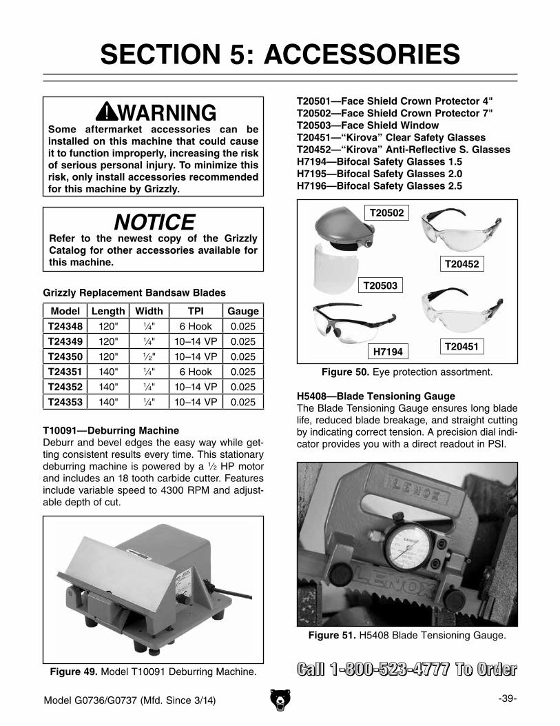
Model G0736/G0737 (Mfd. Since 3/14) -39-
SECTION 5: ACCESSORIESACCESSORIES
Some aftermarket accessories can be installed on this machine that could cause it to function improperly, increasing the risk of serious personal injury. To minimize this risk, only install accessories recommended for this machine by Grizzly.
NOTICERefer to the newest copy of the Grizzly Catalog for other accessories available for this machine.
Figure 51. H5408 Blade Tensioning Gauge.
H5408—Blade Tensioning GaugeThe Blade Tensioning Gauge ensures long blade life, reduced blade breakage, and straight cutting by indicating correct tension. A precision dial indi-cator provides you with a direct readout in PSI.
Grizzly Replacement Bandsaw Blades
Model Length Width TPI Gauge
T24348 120" 1⁄4" 6 Hook 0.025
T24349 120" 1⁄4" 10–14 VP 0.025
T24350 120" 1⁄2" 10–14 VP 0.025
T24351 140" 1⁄4" 6 Hook 0.025
T24352 140" 1⁄4" 10–14 VP 0.025
T24353 140" 1⁄4" 10–14 VP 0.025
T10091—Deburring MachineDeburr and bevel edges the easy way while get-ting consistent results every time. This stationary deburring machine is powered by a 1⁄2 HP motor and includes an 18 tooth carbide cutter. Features include variable speed to 4300 RPM and adjust-able depth of cut.
Figure 49. Model T10091 Deburring Machine.
T20451
T20452
T20502
T20503
H7194
T20501—Face Shield Crown Protector 4"T20502—Face Shield Crown Protector 7"T20503—Face Shield WindowT20451—“Kirova” Clear Safety GlassesT20452—“Kirova” Anti-Reflective S. GlassesH7194—Bifocal Safety Glasses 1.5H7195—Bifocal Safety Glasses 2.0H7196—Bifocal Safety Glasses 2.5
Figure 50. Eye protection assortment.

-40- Model G0736/G0737 (Mfd. Since 3/14)
Recommended Metal ProtectantsG5562—SLIPIT® 1 Qt. GelG5563—SLIPIT® 12 oz SprayG2871—Boeshield® T-9 12 oz SprayG2870—Boeshield® T-9 4 oz SprayH3788—G96® Gun Treatment 12 oz SprayH3789—G96® Gun Treatment 4.5 oz Spray
Figure 52. Recommended products for protect-ing unpainted cast iron/steel part on machinery.
G0692—14" Dry Cut Metal SawT20920—14" 58-Tooth Blade (for general use)Unlike abrasive metal-cutting saws that slowly erode to maintain a cutting edge, the dry cut saw uses a carbide-tipped blade that is specially made to cut metal. Full cutting capacity is maintained through every cut and the slower blade speed results in cuts that are second to none! For those that need consistency and performance, this is the saw for you! Blade not included.
Figure 53. Model G0692 14" Dry Cut Metal Saw.
G4030—6 1⁄2" x 10" Horizontal Metal-Cutting BandsawThis full featured machine has everything you need in a horizontal metal-cutting bandsaw. From its solid supporting cast-iron base and quick posi-tioning vise, to its rotary pump powered coolant system, this workhorse is at home in the hobby shop as well as the full production shop. Features locking roller cabinet for easy mobility, hydraulic feed for smooth cutting, vertical saw table and removable coolant tank for easy cleaning. So whatever your need this horizontal metal-cutting bandsaw will fit the bill.
Figure 54. Model G4030 Horizontal Metal-Cutting Bandsaw
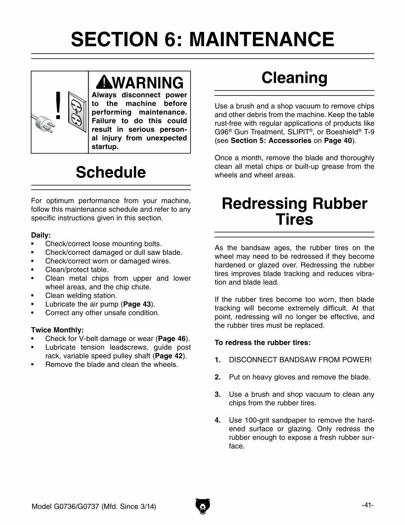
Model G0736/G0737 (Mfd. Since 3/14) -41-
SECTION 6: MAINTENANCE
Always disconnect power to the machine before performing maintenance. Failure to do this could result in serious person-al injury from unexpected startup.
For optimum performance from your machine, follow this maintenance schedule and refer to any specific instructions given in this section.
Daily:• Check/correct loose mounting bolts.• Check/correct damaged or dull saw blade.• Check/correct worn or damaged wires.• Clean/protect table.• Clean metal chips from upper and lower
wheel areas, and the chip chute.• Clean welding station.• Lubricate the air pump (Page 43).• Correct any other unsafe condition.
Twice Monthly:• Check for V-belt damage or wear (Page 46).• Lubricate tension leadscrews, guide post
rack, variable speed pulley shaft (Page 42).• Remove the blade and clean the wheels.
Schedule
Use a brush and a shop vacuum to remove chips and other debris from the machine. Keep the table rust-free with regular applications of products like G96® Gun Treatment, SLIPIT®, or Boeshield® T-9 (see Section 5: Accessories on Page 40).
Once a month, remove the blade and thoroughly clean all metal chips or built-up grease from the wheels and wheel areas.
Cleaning
Redressing Rubber Tires
As the bandsaw ages, the rubber tires on the wheel may need to be redressed if they become hardened or glazed over. Redressing the rubber tires improves blade tracking and reduces vibra-tion and blade lead.
If the rubber tires become too worn, then blade tracking will become extremely difficult. At that point, redressing will no longer be effective, and the rubber tires must be replaced.
To redress the rubber tires:
1. DISCONNECT BANDSAW FROM POWER!
2. Put on heavy gloves and remove the blade.
3. Use a brush and shop vacuum to clean any chips from the rubber tires.
4. Use 100-grit sandpaper to remove the hard-ened surface or glazing. Only redress the rubber enough to expose a fresh rubber sur-face.
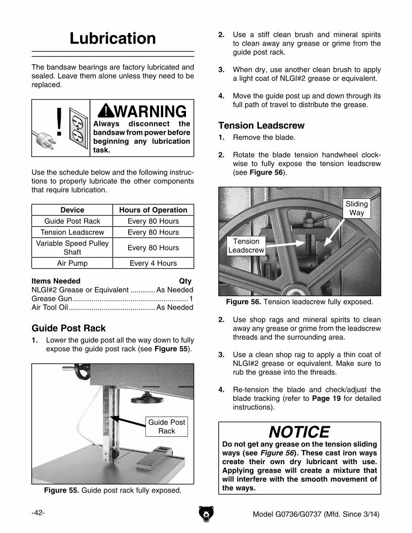
-42- Model G0736/G0737 (Mfd. Since 3/14)
Lubrication
The bandsaw bearings are factory lubricated and sealed. Leave them alone unless they need to be replaced.
2. Use a stiff clean brush and mineral spirits to clean away any grease or grime from the guide post rack.
3. When dry, use another clean brush to apply a light coat of NLGI#2 grease or equivalent.
4. Move the guide post up and down through its full path of travel to distribute the grease.
Tension Leadscrew1. Remove the blade.
2. Rotate the blade tension handwheel clock-wise to fully expose the tension leadscrew (see Figure 56).
2. Use shop rags and mineral spirits to clean away any grease or grime from the leadscrew threads and the surrounding area.
3. Use a clean shop rag to apply a thin coat of NLGI#2 grease or equivalent. Make sure to rub the grease into the threads.
4. Re-tension the blade and check/adjust the blade tracking (refer to Page 19 for detailed instructions).
Do not get any grease on the tension sliding ways (see Figure 56). These cast iron ways create their own dry lubricant with use. Applying grease will create a mixture that will interfere with the smooth movement of the ways.
Figure 56. Tension leadscrew fully exposed.
TensionLeadscrew
SlidingWay
Figure 55. Guide post rack fully exposed.
Guide PostRack
Always disconnect the bandsaw from power before beginning any lubrication task.
Use the schedule below and the following instruc-tions to properly lubricate the other components that require lubrication.
Device Hours of Operation
Guide Post Rack Every 80 Hours
Tension Leadscrew Every 80 Hours
Variable Speed Pulley Shaft
Every 80 Hours
Air Pump Every 4 Hours
Items Needed QtyNLGI#2 Grease or Equivalent ............ As NeededGrease Gun ........................................................ 1Air Tool Oil .......................................... As Needed
Guide Post Rack1. Lower the guide post all the way down to fully
expose the guide post rack (see Figure 55).
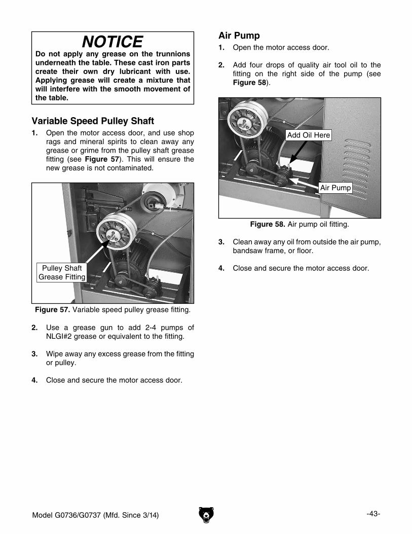
Model G0736/G0737 (Mfd. Since 3/14) -43-
Do not apply any grease on the trunnions underneath the table. These cast iron parts create their own dry lubricant with use. Applying grease will create a mixture that will interfere with the smooth movement of the table.
Variable Speed Pulley Shaft1. Open the motor access door, and use shop
rags and mineral spirits to clean away any grease or grime from the pulley shaft grease fitting (see Figure 57). This will ensure the new grease is not contaminated.
2. Use a grease gun to add 2-4 pumps of NLGI#2 grease or equivalent to the fitting.
3. Wipe away any excess grease from the fitting or pulley.
4. Close and secure the motor access door.
Air Pump1. Open the motor access door.
2. Add four drops of quality air tool oil to the fitting on the right side of the pump (see Figure 58).
3. Clean away any oil from outside the air pump, bandsaw frame, or floor.
4. Close and secure the motor access door.
Figure 57. Variable speed pulley grease fitting.
Pulley ShaftGrease Fitting
Figure 58. Air pump oil fitting.
Air Pump
Add Oil Here
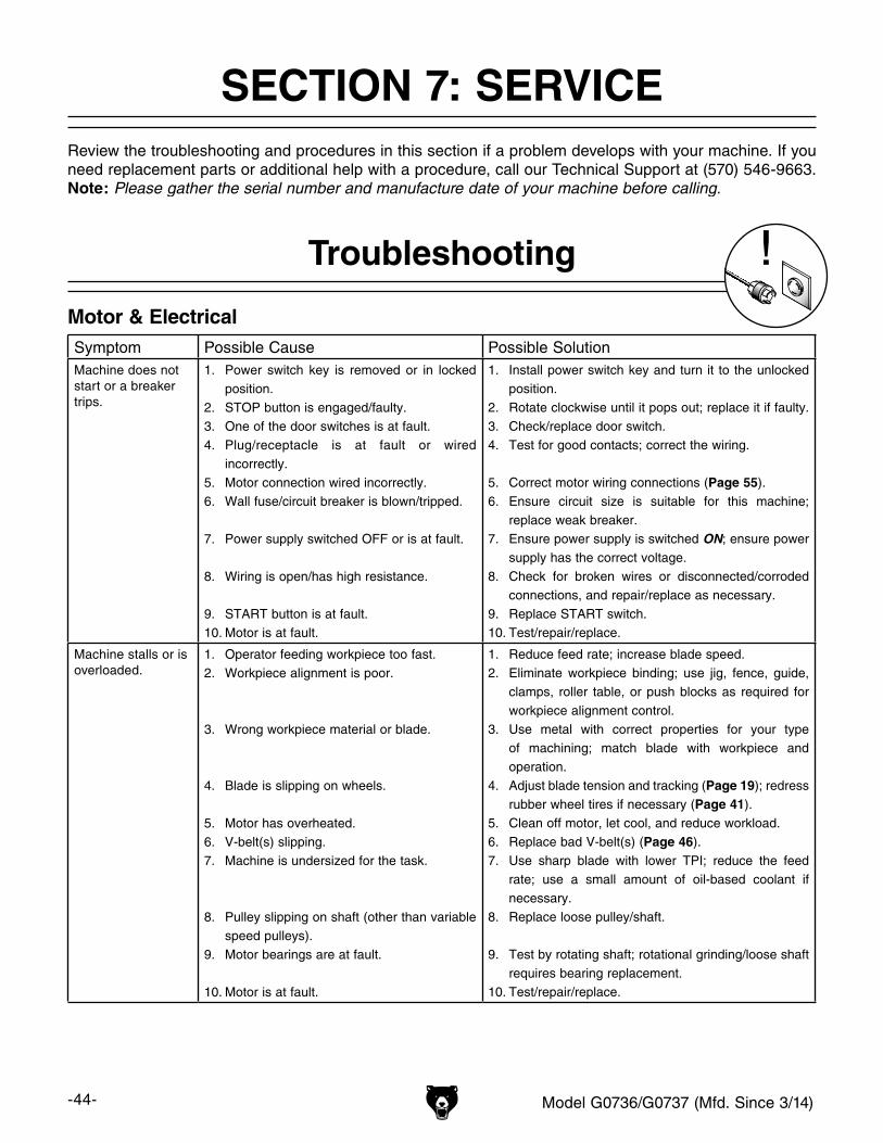
-44- Model G0736/G0737 (Mfd. Since 3/14)
Review the troubleshooting and procedures in this section if a problem develops with your machine. If you need replacement parts or additional help with a procedure, call our Technical Support at (570) 546-9663. Note: Please gather the serial number and manufacture date of your machine before calling.
SECTION 7: SERVICE
Troubleshooting
Motor & ElectricalSymptom Possible Cause Possible SolutionMachine does not start or a breaker trips.
1. Power switch key is removed or in locked position.
2. STOP button is engaged/faulty.3. One of the door switches is at fault.4. Plug/receptacle is at fault or wired
incorrectly.5. Motor connection wired incorrectly.6. Wall fuse/circuit breaker is blown/tripped.
7. Power supply switched OFF or is at fault.
8. Wiring is open/has high resistance.
9. START button is at fault.10. Motor is at fault.
1. Install power switch key and turn it to the unlocked position.
2. Rotate clockwise until it pops out; replace it if faulty.3. Check/replace door switch.4. Test for good contacts; correct the wiring.
5. Correct motor wiring connections (Page 55).6. Ensure circuit size is suitable for this machine;
replace weak breaker.7. Ensure power supply is switched ON; ensure power
supply has the correct voltage.8. Check for broken wires or disconnected/corroded
connections, and repair/replace as necessary. 9. Replace START switch.10. Test/repair/replace.
Machine stalls or is overloaded.
1. Operator feeding workpiece too fast.2. Workpiece alignment is poor.
3. Wrong workpiece material or blade.
4. Blade is slipping on wheels.
5. Motor has overheated.6. V-belt(s) slipping.7. Machine is undersized for the task.
8. Pulley slipping on shaft (other than variable speed pulleys).
9. Motor bearings are at fault.
10. Motor is at fault.
1. Reduce feed rate; increase blade speed.2. Eliminate workpiece binding; use jig, fence, guide,
clamps, roller table, or push blocks as required for workpiece alignment control.
3. Use metal with correct properties for your type of machining; match blade with workpiece and operation.
4. Adjust blade tension and tracking (Page 19); redress rubber wheel tires if necessary (Page 41).
5. Clean off motor, let cool, and reduce workload.6. Replace bad V-belt(s) (Page 46).7. Use sharp blade with lower TPI; reduce the feed
rate; use a small amount of oil-based coolant if necessary.
8. Replace loose pulley/shaft.
9. Test by rotating shaft; rotational grinding/loose shaft requires bearing replacement.
10. Test/repair/replace.
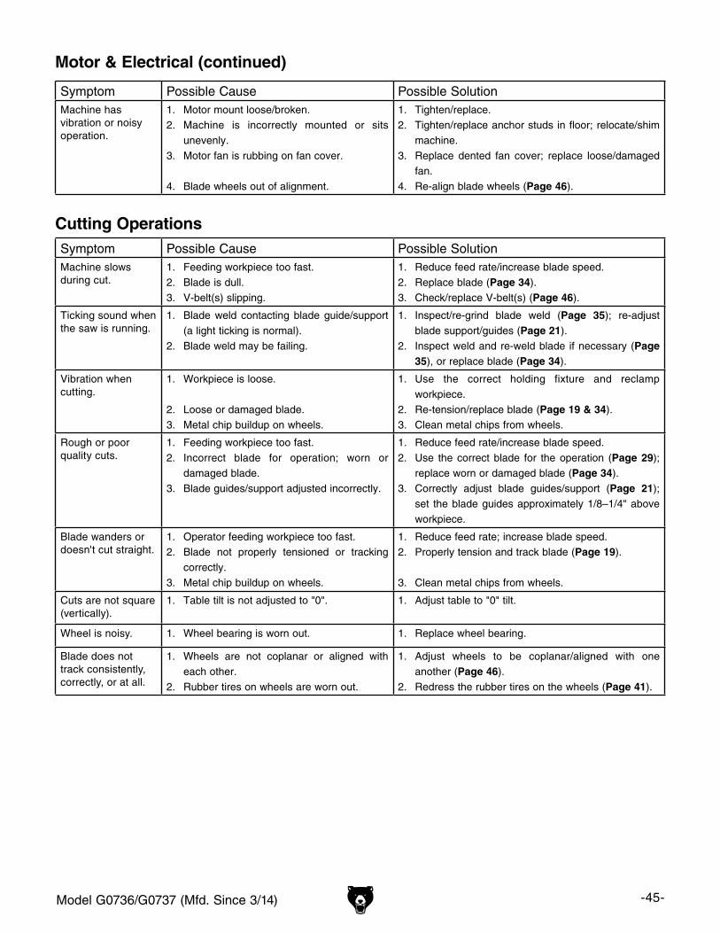
Model G0736/G0737 (Mfd. Since 3/14) -45-
Motor & Electrical (continued)
Symptom Possible Cause Possible SolutionMachine has vibration or noisy operation.
1. Motor mount loose/broken.2. Machine is incorrectly mounted or sits
unevenly.3. Motor fan is rubbing on fan cover.
4. Blade wheels out of alignment.
1. Tighten/replace.2. Tighten/replace anchor studs in floor; relocate/shim
machine.3. Replace dented fan cover; replace loose/damaged
fan.4. Re-align blade wheels (Page 46).
Cutting OperationsSymptom Possible Cause Possible SolutionMachine slows during cut.
1. Feeding workpiece too fast.2. Blade is dull.3. V-belt(s) slipping.
1. Reduce feed rate/increase blade speed.2. Replace blade (Page 34).3. Check/replace V-belt(s) (Page 46).
Ticking sound when the saw is running.
1. Blade weld contacting blade guide/support (a light ticking is normal).
2. Blade weld may be failing.
1. Inspect/re-grind blade weld (Page 35); re-adjust blade support/guides (Page 21).
2. Inspect weld and re-weld blade if necessary (Page 35), or replace blade (Page 34).
Vibration when cutting.
1. Workpiece is loose.
2. Loose or damaged blade.3. Metal chip buildup on wheels.
1. Use the correct holding fixture and reclamp workpiece.
2. Re-tension/replace blade (Page 19 & 34).3. Clean metal chips from wheels.
Rough or poor quality cuts.
1. Feeding workpiece too fast.2. Incorrect blade for operation; worn or
damaged blade.3. Blade guides/support adjusted incorrectly.
1. Reduce feed rate/increase blade speed.2. Use the correct blade for the operation (Page 29);
replace worn or damaged blade (Page 34).3. Correctly adjust blade guides/support (Page 21);
set the blade guides approximately 1/8–1/4" above workpiece.
Blade wanders or doesn't cut straight.
1. Operator feeding workpiece too fast.2. Blade not properly tensioned or tracking
correctly.3. Metal chip buildup on wheels.
1. Reduce feed rate; increase blade speed.2. Properly tension and track blade (Page 19).
3. Clean metal chips from wheels.
Cuts are not square (vertically).
1. Table tilt is not adjusted to "0". 1. Adjust table to "0" tilt.
Wheel is noisy. 1. Wheel bearing is worn out. 1. Replace wheel bearing.
Blade does not track consistently, correctly, or at all.
1. Wheels are not coplanar or aligned with each other.
2. Rubber tires on wheels are worn out.
1. Adjust wheels to be coplanar/aligned with one another (Page 46).
2. Redress the rubber tires on the wheels (Page 41).
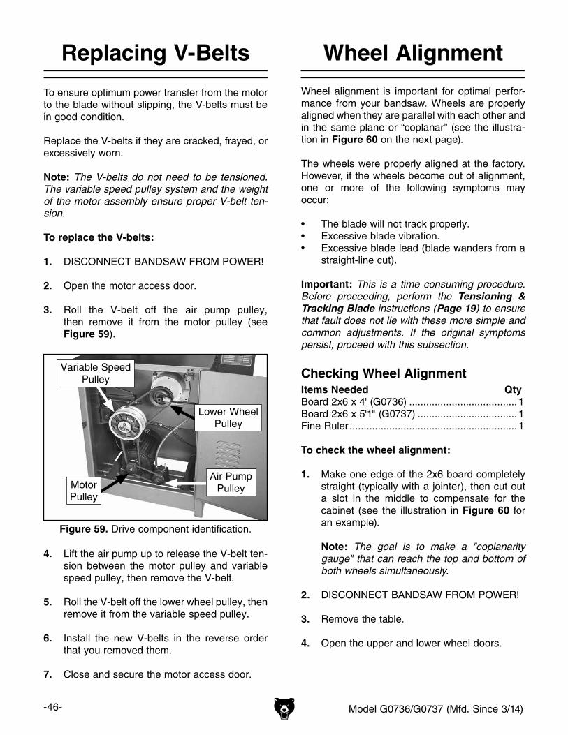
-46- Model G0736/G0737 (Mfd. Since 3/14)
Replacing V-Belts
To ensure optimum power transfer from the motor to the blade without slipping, the V-belts must be in good condition.
Replace the V-belts if they are cracked, frayed, or excessively worn.
Note: The V-belts do not need to be tensioned. The variable speed pulley system and the weight of the motor assembly ensure proper V-belt ten-sion.
To replace the V-belts:
1. DISCONNECT BANDSAW FROM POWER!
2. Open the motor access door.
3. Roll the V-belt off the air pump pulley, then remove it from the motor pulley (see Figure 59).
4. Lift the air pump up to release the V-belt ten-sion between the motor pulley and variable speed pulley, then remove the V-belt.
5. Roll the V-belt off the lower wheel pulley, then remove it from the variable speed pulley.
6. Install the new V-belts in the reverse order that you removed them.
7. Close and secure the motor access door.
Wheel Alignment
Wheel alignment is important for optimal perfor-mance from your bandsaw. Wheels are properly aligned when they are parallel with each other and in the same plane or “coplanar” (see the illustra-tion in Figure 60 on the next page).
The wheels were properly aligned at the factory. However, if the wheels become out of alignment, one or more of the following symptoms may occur:
• The blade will not track properly.• Excessive blade vibration.• Excessive blade lead (blade wanders from a
straight-line cut).
Important: This is a time consuming procedure. Before proceeding, perform the Tensioning & Tracking Blade instructions (Page 19) to ensure that fault does not lie with these more simple and common adjustments. If the original symptoms persist, proceed with this subsection.
Checking Wheel AlignmentItems Needed QtyBoard 2x6 x 4' (G0736) ...................................... 1Board 2x6 x 5'1" (G0737) ................................... 1Fine Ruler ........................................................... 1
To check the wheel alignment:
1. Make one edge of the 2x6 board completely straight (typically with a jointer), then cut out a slot in the middle to compensate for the cabinet (see the illustration in Figure 60 for an example).
Note: The goal is to make a "coplanarity gauge" that can reach the top and bottom of both wheels simultaneously.
2. DISCONNECT BANDSAW FROM POWER!
3. Remove the table.
4. Open the upper and lower wheel doors.
Figure 59. Drive component identification.
Variable SpeedPulley
Lower WheelPulley
MotorPulley
Air PumpPulley
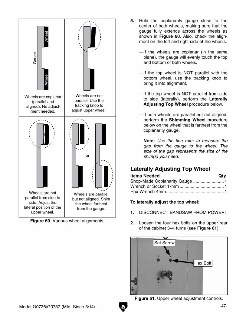
Model G0736/G0737 (Mfd. Since 3/14) -47-
Gau
ge
Whe
elW
heel
Wheels are coplanar (parallel and
aligned). No adjust-ment needed.
Wheels are not parallel. Use the tracking knob to
adjust upper wheel.
Wheels are not parallel from side to
side. Adjust the lateral position of the
upper wheel.
or
Wheels are parallel but not aligned. Shim
the wheel farthest from the gauge.
Figure 60. Various wheel alignments.
5. Hold the coplanarity gauge close to the center of both wheels, making sure that the gauge fully extends across the wheels as shown in Figure 60. Also, check the align-ment on the left and right side of the wheels.
— If the wheels are coplanar (in the same plane), the gauge will evenly touch the top and bottom of both wheels.
— If the top wheel is NOT parallel with the bottom wheel, use the tracking knob to bring it into alignment.
— If the top wheel is NOT parallel from side to side (laterally), perform the Laterally Adjusting Top Wheel procedure below.
— If both wheels are parallel but not aligned, perform the Shimming Wheel procedure below on the wheel that is farthest from the coplanarity gauge.
Note: Use the fine ruler to measure the gap from the gauge to the wheel. The size of the gap represents the size of the shim(s) you need.
Laterally Adjusting Top WheelItems Needed QtyShop-Made Coplanarity Gauge ......................... 1Wrench or Socket 17mm .................................... 1Hex Wrench 4mm ............................................... 1
To laterally adjust the top wheel:
1. DISCONNECT BANDSAW FROM POWER!
2. Loosen the four hex bolts on the upper rear of the cabinet 3–4 turns (see Figure 61).
Figure 61. Upper wheel adjustment controls.
Hex Bolt
Set Screw

-48- Model G0736/G0737 (Mfd. Since 3/14)
3. In even amounts, make small changes to the set screws to compensate for the direction that the upper wheel is out of alignment.
Example: If the upper wheel is twisted to the right from the lower wheel (as viewed from the front), thread the right-hand set screws (as viewed from the rear) out and the left-hand set screws in—all in even amounts.
4. Snug the four hex bolts, then use the gauge to re-check wheel coplanarity.
5. Repeat Steps 2–4 as necessary to bring the upper wheel into alignment with the lower wheel.
6. Close and secure both wheel doors.
Shimming WheelItems Needed QtyShop-Made Coplanarity Gauge ......................... 1External Retaining Ring Pliers (Upper Wheel) ... 1Hex Wrench 8mm (Lower Wheel) ...................... 1Shims .................................................. As Needed
Note: Flat washers and thin electrical washers work well as shims and can be obtained from your local hardware store.
To shim a wheel:
1. DISCONNECT BANDSAW FROM POWER!
2. Remove the bandsaw blade.
3. If installed, remove the table.
4. Carefully remove the wheel that needs to be shimmed, add the shims, then re-install the wheel.
5. Use the gauge to re-check wheel coplanarity.
6. If necessary, repeat Steps 4–5 until the wheels are coplanar.
7. Close and secure both wheel doors.
Blade Guides & Supports
With use, the faces of the blade guides will wear at an angle and it may become difficult to prop-erly adjust them. If this is the case, swap and turn blade guides over so that they are reversed rela-tive to the blade (see Figure 62).
When the blade guides are no longer effective after reversing them, then replace them with new guides (Grizzly Part Number P0736221).
Swap &Turn Over
RotateBlade Support
WearMark
Figure 62. Blade guide and support orientation.
As the blade is deflected back into the blade support during operation, a groove will eventu-ally wear into the blade support. As this groove becomes deeper, it can affect the accuracy of the cut. When this happens, loosen the blade support cap screw and rotate the blade support 90°, as shown in Figure 62.
If necessary, the end of the blade support can be ground flat to extend its life. When it becomes too short to properly support the blade, replace it with a new one (Grizzly Part Number P0736223).
Note: Make sure to re-adjust the blade guides and support as directed in Adjusting Blade Guide Assemblies on Page 21 after making these changes.
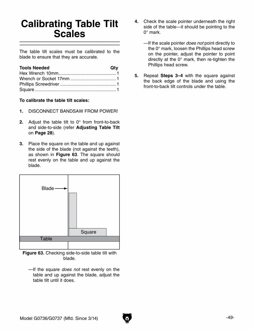
Model G0736/G0737 (Mfd. Since 3/14) -49-
Calibrating Table Tilt Scales
The table tilt scales must be calibrated to the blade to ensure that they are accurate.
Tools Needed QtyHex Wrench 10mm ............................................. 1Wrench or Socket 17mm .................................... 1Phillips Screwdriver ............................................ 1Square ................................................................ 1
To calibrate the table tilt scales:
1. DISCONNECT BANDSAW FROM POWER!
2. Adjust the table tilt to 0° from front-to-back and side-to-side (refer Adjusting Table Tilt on Page 28).
3. Place the square on the table and up against the side of the blade (not against the teeth), as shown in Figure 63. The square should rest evenly on the table and up against the blade.
Figure 63. Checking side-to-side table tilt with blade.
4. Check the scale pointer underneath the right side of the table—it should be pointing to the 0° mark.
— If the scale pointer does not point directly to the 0° mark, loosen the Phillips head screw on the pointer, adjust the pointer to point directly at the 0° mark, then re-tighten the Phillips head screw.
5. Repeat Steps 3–4 with the square against the back edge of the blade and using the front-to-back tilt controls under the table.
— If the square does not rest evenly on the table and up against the blade, adjust the table tilt until it does.
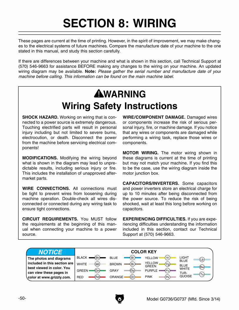
-50- Model G0736/G0737 (Mfd. Since 3/14)
SHOCK HAZARD. Working on wiring that is con-nected to a power source is extremely dangerous. Touching electrified parts will result in personal injury including but not limited to severe burns, electrocution, or death. Disconnect the power from the machine before servicing electrical com-ponents!
MODIFICATIONS. Modifying the wiring beyond what is shown in the diagram may lead to unpre-dictable results, including serious injury or fire. This includes the installation of unapproved after-market parts.
WIRE CONNECTIONS. All connections must be tight to prevent wires from loosening during machine operation. Double-check all wires dis-connected or connected during any wiring task to ensure tight connections.
CIRCUIT REQUIREMENTS. You MUST follow the requirements at the beginning of this man-ual when connecting your machine to a power source.
WIRE/COMPONENT DAMAGE. Damaged wires or components increase the risk of serious per-sonal injury, fire, or machine damage. If you notice that any wires or components are damaged while performing a wiring task, replace those wires or components.
MOTOR WIRING. The motor wiring shown in these diagrams is current at the time of printing but may not match your machine. If you find this to be the case, use the wiring diagram inside the motor junction box.
CAPACITORS/INVERTERS. Some capacitors and power inverters store an electrical charge for up to 10 minutes after being disconnected from the power source. To reduce the risk of being shocked, wait at least this long before working on capacitors.
EXPERIENCING DIFFICULTIES. If you are expe-riencing difficulties understanding the information included in this section, contact our Technical Support at (570) 546-9663.
Wiring Safety Instructions
The photos and diagrams included in this section are best viewed in color. You can view these pages in color at www.grizzly.com.
These pages are current at the time of printing. However, in the spirit of improvement, we may make chang-es to the electrical systems of future machines. Compare the manufacture date of your machine to the one stated in this manual, and study this section carefully.
If there are differences between your machine and what is shown in this section, call Technical Support at (570) 546-9663 for assistance BEFORE making any changes to the wiring on your machine. An updated wiring diagram may be available. Note: Please gather the serial number and manufacture date of your machine before calling. This information can be found on the main machine label.
SECTION 8: WIRINGmachine
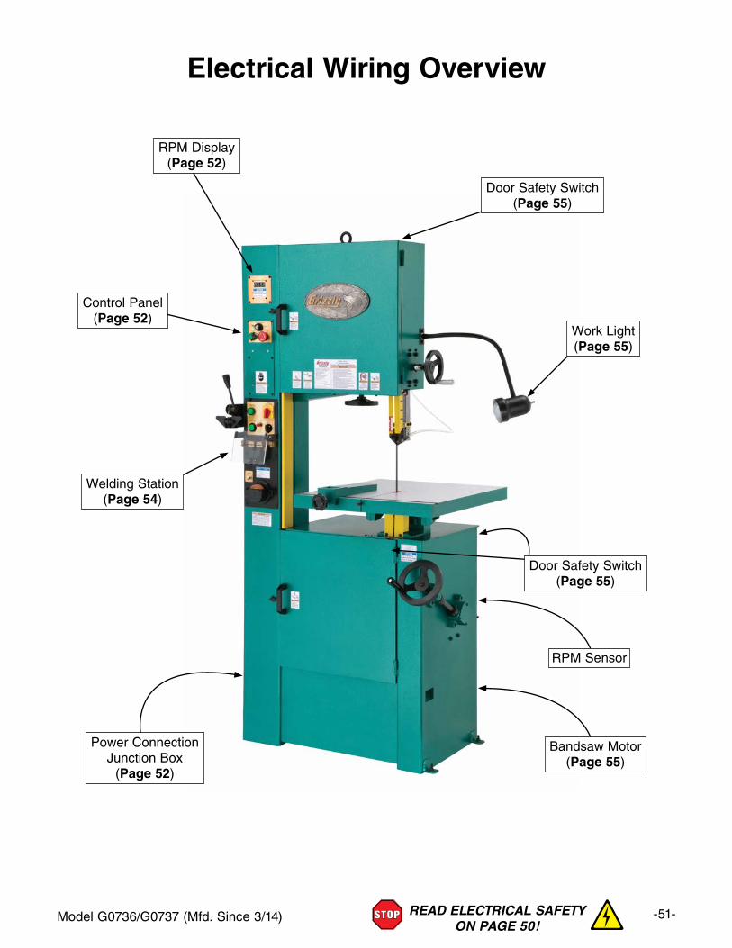
Model G0736/G0737 (Mfd. Since 3/14) -51-READ ELECTRICAL SAFETY ON PAGE 50!
Electrical Wiring Overview
RPM Display(Page 52)
Door Safety Switch(Page 55)
Welding Station(Page 54)
Control Panel(Page 52)
Bandsaw Motor(Page 55)
Power ConnectionJunction Box
(Page 52)
Door Safety Switch(Page 55)
RPM Sensor
Work Light(Page 55)
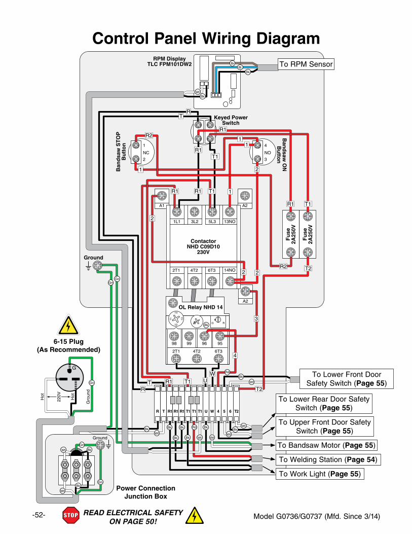
-52- Model G0736/G0737 (Mfd. Since 3/14)READ ELECTRICAL SAFETY ON PAGE 50!
Control Panel Wiring Diagram
A1
2
1
NC
3
4
NO
A2
A2
98
Ground
2T1 6T3
99
4T2
2T1
Hot
Hot
Ground
6T34T2
1L1 5L3 13NO
14NO
3L2
96 95
ContactorNHD C09D10
230V
Ban
dsa
w S
TO
PB
utt
on
Ban
dsaw
ON
Bu
tton
Keyed PowerSwitch
OL Relay NHD 1414
12
13
11
O R
Fu
se2A
250V
Fu
se2A
250V
R
Ground
T U W 4 5 6 T2R1 R1 R1 T1 T1 T1
RPM DisplayTLC FPM101DW2
6-15 Plug(As Recommended)
Power ConnectionJunction Box
G
220V
U
2
2
3
4
W
TR
T1R1
R1
RT
R1
R1
R1
R1
T1
T1
T1
1
11
1
R2
R2
T2
T2
2
2
To Lower Front DoorSafety Switch (Page 55)
To Lower Rear Door SafetySwitch (Page 55)
To Upper Front Door SafetySwitch (Page 55)
To Welding Station (Page 54)
To Bandsaw Motor (Page 55)
To Work Light (Page 55)
To RPM Sensor
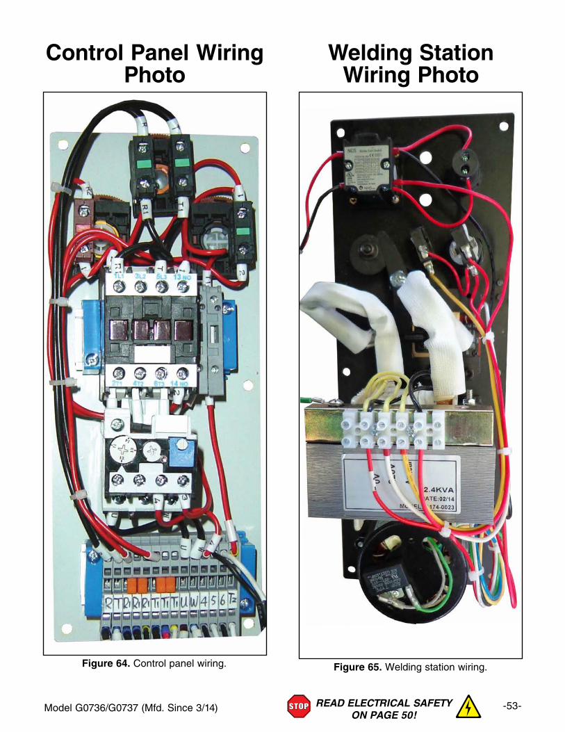
Model G0736/G0737 (Mfd. Since 3/14) -53-READ ELECTRICAL SAFETY ON PAGE 50!
Control Panel Wiring Photo
Welding Station Wiring Photo
Figure 64. Control panel wiring. Figure 65. Welding station wiring.
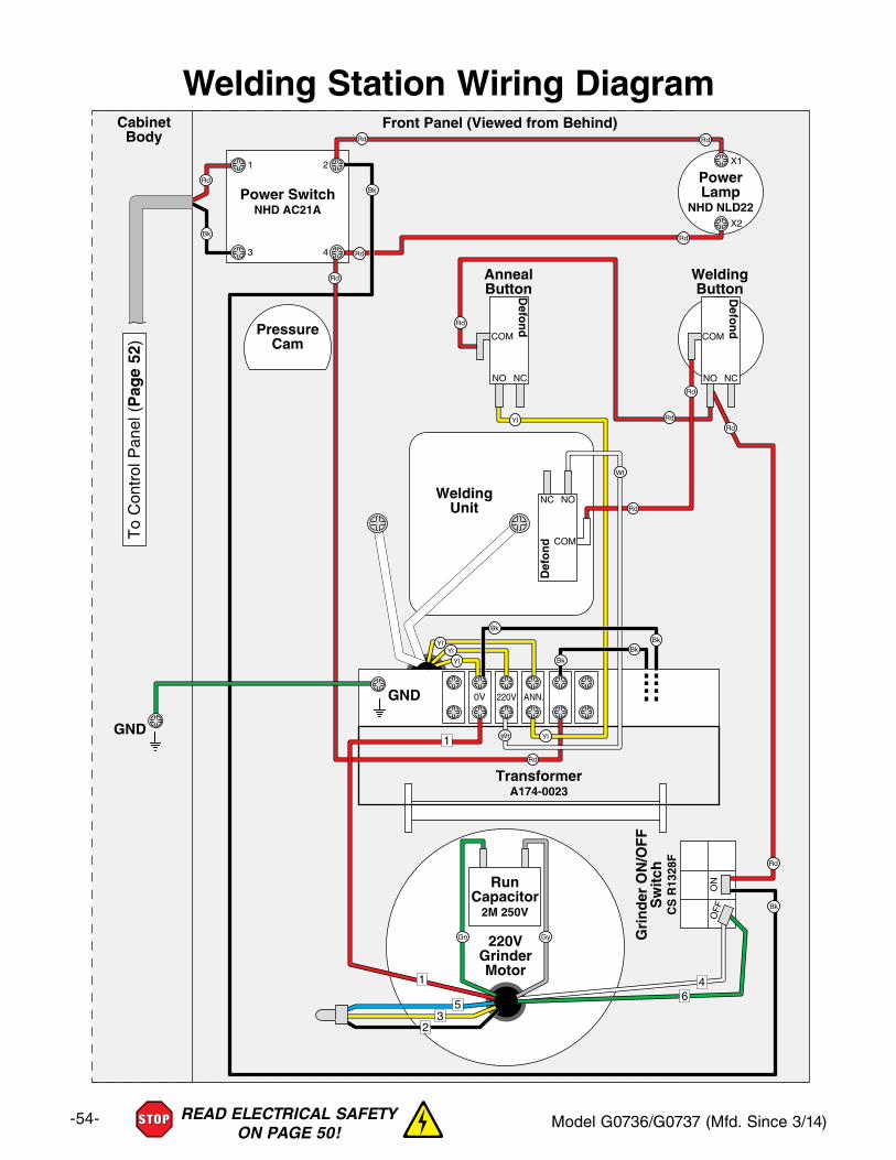
-54- Model G0736/G0737 (Mfd. Since 3/14)READ ELECTRICAL SAFETY ON PAGE 50!
Welding Station Wiring Diagram
1 2
3 4
Power SwitchNHD AC21A
PressureCam
X1
X2
PowerLamp
NHD NLD22
TransformerA174-0023
0V 220V ANN.
AnnealButton
Front Panel (Viewed from Behind)CabinetBody
WeldingButton
Gri
nd
er O
N/O
FF
Sw
itch
CS
R13
28F
ON
OFF
220VGrinderMotor
1
1
53
46
2
COM
NONC
Def
on
d
COM
NO NC
Defo
nd
COM
NO NCD
efon
d
RunCapacitor
2M 250V
WeldingUnit
GND
GND
To
Con
trol
Pan
el (
Pag
e 52
)
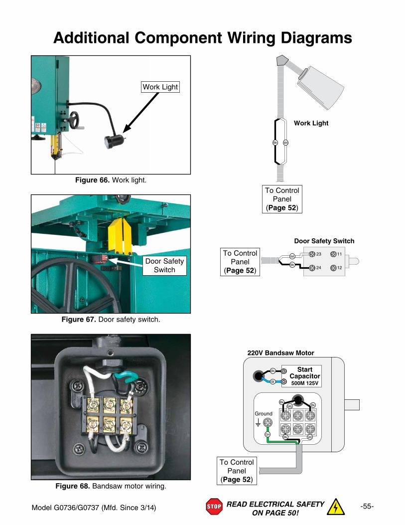
Model G0736/G0737 (Mfd. Since 3/14) -55-READ ELECTRICAL SAFETY ON PAGE 50!
Additional Component Wiring Diagrams
Figure 66. Work light.
Work Light
Work Light
Door Safety Switch
23 11
24 12
Ground
StartCapacitor500M 125V
220V Bandsaw Motor
Work Light
Door Safety Switch
23 11
24 12
Ground
StartCapacitor500M 125V
220V Bandsaw Motor
Work Light
Door Safety Switch
23 11
24 12
Ground
StartCapacitor500M 125V
220V Bandsaw Motor
Figure 68. Bandsaw motor wiring.
To Control Panel
(Page 52)
To Control Panel
(Page 52)
To Control Panel
(Page 52)
Figure 67. Door safety switch.
Door SafetySwitch
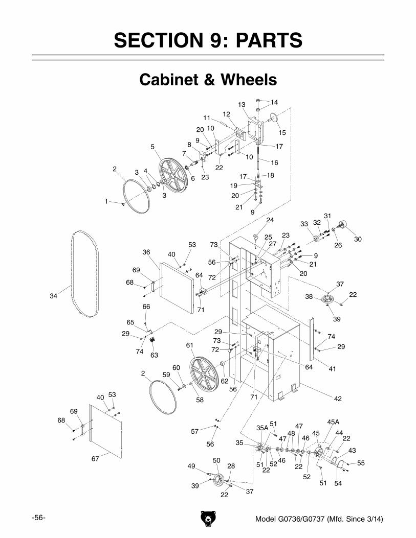
-56- Model G0736/G0737 (Mfd. Since 3/14)
1
2
2
3
3
4
5
6
78
9
9
9
10
10
11 1213 14
15
16
17
17 18
19
20
20
20
21
21
22
22
2222
22
22
23
23
24
2527
28
29
29
29
2630
313233
34
35A
35
36
37
37
38
39
39
40
40
41
42
43
44
45A
45
46
4647
4748
4950
51
51
51
52
52
53
53
54
55
56
56
57
58
5960
61
62
63
64
64
65
66
67
68
68
69
69
71
71
72
7273
73
74
74
56
Cabinet & Wheels
SECTION 9: PARTS

Model G0736/G0737 (Mfd. Since 3/14) -57-
Cabinet & Wheels Parts ListREF PART # DESCRIPTION REF PART # DESCRIPTION1 PR11M EXT RETAINING RING 25MM 37 PK08M KEY 5 X 5 X 162 P0736002 WHEEL TIRE, RUBBER (G0736) 38 P0736038 TENSIONING HANDWHEEL2 P0737002 WHEEL TIRE, RUBBER (G0737) 39 PR07M EXT RETAINING RING 18MM3 P6005ZZ BALL BEARING 6005ZZ 40 PW03M FLAT WASHER 6MM4 PR25M INT RETAINING RING 47MM 41 P0736041 BLADE GUARD5 P0736005 UPPER WHEEL (G0736) 42 P0736042 CABINET (G0736)5 P0737005 UPPER WHEEL (G0737) 42 P0737042 CABINET (G0737)6 P0736006 WHEEL SHAFT LOCK COLLAR 43 P0736043 GEARBOX COVER GASKET7 P0736007 UPPER WHEEL SHAFT 44 P0736044 FLANGE BUSHING8 P0736008 PIVOT BRACKET 45A P0736045A GEARBOX HOUSING ASSEMBLY9 PB01M HEX BOLT M10-1.5 X 30 45 P0736045 GEARBOX HOUSING10 P0736010 SLIDE BRACKET GUIDE 46 P51104 THRUST BEARING 5110411 P0736011 PIVOT BRACKET AXLE 47 P0736047 DUST DEFLECTOR12 P0736012 SLIDE BLOCK 48 P0736048 LOCK COLLAR13 P0736013 SLIDE BLOCK HOUSING 49 P0736049 HANDWHEEL HANDLE14 PN27 HEX NUT 5/8-11 LH 50 P0736050 VARIABLE SPEED HANDWHEEL15 P0736015 BLADE TRACKING RAM 51 PCAP31M CAP SCREW M8-1.25 X 2516 P0736016 TENSIONING LEADSCREW 52 P0736052 BUSHING17 P0736017 SPACER 53 PN01M HEX NUT M6-118 P0736018 COMPRESSION SPRING 54 P0736054 GEARBOX HOUSING COVER19 P0736019 SPRING RETAINING PLATE 55 PB96M HEX BOLT M5-.8 X 1020 PW04M FLAT WASHER 10MM 56 PW01M FLAT WASHER 8MM21 PLW06M LOCK WASHER 10MM 57 PN03M HEX NUT M8-1.2522 PSS02M SET SCREW M6-1 X 6 58 PK28M KEY 7 X 7 X 3023 PSS20M SET SCREW M8-1.25 X 8 59 PCAP197M CAP SCREW M10-1.5 X 25 LH24 P0736024 LIFTING EYE BOLT M12-1.75 X 20 60 P0736060 WHEEL FLAT WASHER 10MM25 PW06M FLAT WASHER 12MM 61 P0736061 LOWER WHEEL (G0736)26 PN09 HEX NUT 5/8-18 61 P0737061 LOWER WHEEL (G0737)27 PN09M HEX NUT M12-1.75 62 P0736062 BUSHING28 P0736028 HANDWHEEL SHAFT 63 P0736063 CHIP BRUSH29 PS05M PHLP HD SCR M5-.8 X 8 64 P0736064 DOOR SWITCH SHINOZAKI AZ-100-IT30 P0736030 TRACKING KNOB BOLT 5/8-18 X 2-1/2 65 P0736065 CHIP BRUSH BRACKET31 PB07M HEX BOLT M8-1.25 X 25 66 PHTEK36M TAP SCREW M5 X 832 PLW04M LOCK WASHER 8MM 67 P0736067 LOWER WHEEL DOOR (G0736)33 P0736033 KNOB BOLT BRACKET 67 P0737067 LOWER WHEEL DOOR (G0737)34 P0736034 BLADE 120" X 1/2" X 0.25" 14 RAKER 68 PB83M HEX BOLT M6-1 X 1634 P0737034 BLADE 140" X 1/2" X 0.25" 14 RAKER 69 P0736069 DOOR HANDLE35A P0736035A PILLOW BLOCK ASSY W/BUSHING 71 PS25M PHLP HD SCR M4-.7 X 3535 P0736035 PILLOW BLOCK 72 P0736072 DOOR LOCK36 P0736036 UPPER WHEEL DOOR (G0736) 73 PCAP03M CAP SCREW M5-.8 X 836 P0737036 UPPER WHEEL DOOR (G0737) 74 PW02M FLAT WASHER 5MM
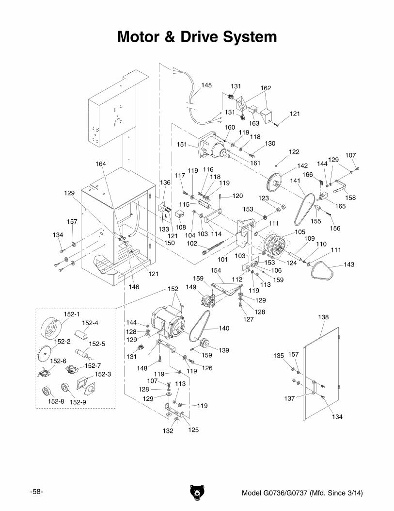
-58- Model G0736/G0737 (Mfd. Since 3/14)
Motor & Drive System
101
102
103
103
104 105
106
107
108
109110
111
111
112113
114
115
116117
118
118
119
119
119
119
120
121
121
121
122
123
124
125
126
159
127128
128129
129
129
130
131
131
131
132
133134
135 157
136
137
134
138
139
140
141
142
143
144129
144
145
146
148119
119
107128
129
113
119
149
150
151
152
152-1
152-2
152-3
152-4
152-5
152-6152-7
152-8 152-9
153
153154
155156
157
158
159159
160
161
162
163
164
165
166

Model G0736/G0737 (Mfd. Since 3/14) -59-
Motor & Drive System Parts ListREF PART # DESCRIPTION REF PART # DESCRIPTION101 P0736101 PULLEY BRACKET 140 P0736140 COGGED V-BELT M-19102 P0736102 VARIABLE SPEED LEADSCREW 141 P0736141 COGGED V-BELT 17-360103 PW01 FLAT WASHER 1/2 142 P0736142 SPEED REDUCTION PULLEY104 PLN06 LOCK NUT 1/2-13 143 P0736143 COGGED V-BELT 17-320105 P0736105 VARIABLE SPEED PULLEY ASSY 144 PN03M HEX NUT M8-1.25106 P0736106 LEADSCREW LOCK NUT 145 P0736145 CONTROL PANEL CORD 14G 3C107 PB09M HEX BOLT M8-1.25 X 20 146 P0736072 DOOR LOCK108 P0736064 DOOR SWITCH SHINOZAKI AZ-100-IT 148 PCB35M CARRIAGE BOLT M8-1.25 X 35109 P0736109 PULLEY SHAFT 149 P0736149 AIR PUMP ASSEMBLY110 PZERK2 GREASE FITTING, STRAIGHT M6-1 X 5 150 P0736150 AIR HOSE 6.6 X 10 X 2200MM (G0736)111 PR09M EXT RETAINING RING 20MM 150 P0737150 AIR HOSE 6.6 X 10 X 2400MM (G0737)112 P0736112 LEADSCREW BLOCK 151 P0736151 REDUCTION GEARBOX (G0736)113 PLN05M LOCK NUT M10-1.5 151 P0737151 REDUCTION GEARBOX (G0737)114 P0736114 PULLEY SHAFT PIVOT ARM 152 P0736152 MOTOR 1-1/2HP 220V 1PH W/KEY (G0736)115 P0736115 GEAR SHAFT PIVOT ARM 152 P0737152 MOTOR 2HP 220V 1PH W/KEY (G0737)116 PB74M HEX BOLT M10-1.5 X 20 152-1 P0736152-1 MOTOR FAN COVER117 PB116M HEX BOLT M10-1.5 X 45 152-2 P0736152-2 MOTOR FAN118 PLW06M LOCK WASHER 10MM 152-3 P0736152-3 MOTOR JUNCTION BOX119 PW04M FLAT WASHER 10MM 152-4 P0736152-4 CAPACITOR COVER120 PB20M HEX BOLT M8-1.25 X 35 152-5 P0736152-5 S CAPACITOR 400M 250V (G0736)121 PS05M PHLP HD SCR M5-.8 X 8 152-5 P0737152-5 S CAPACITOR 500M 250V (G0737)122 PSS20M SET SCREW M8-1.25 X 8 152-6 P0736152-6 CONTACT PLATE 5/8"ID123 PN09M HEX NUT M12-1.75 152-7 P0736152-7 CENTRIFUGAL SWITCH 1725RPM 5/8"ID124 PB72 HEX BOLT 1/2-13 X 2 152-8 P6203ZZ BALL BEARING 6203ZZ125 P0736125 MOTOR MOUNT PIVOT BRACKET 152-9 P6202ZZ BALL BEARING 6202ZZ126 PB14M HEX BOLT M10-1.5 X 35 153 P51101 THRUST BEARING 51101127 PB87M HEX BOLT M8-1.25 X 15 154 P0736154 AIR PUMP MOUNTING BRACKET128 PLW04M LOCK WASHER 8MM 155 P0736155 SPEED SENSOR TARGET129 PW01M FLAT WASHER 8MM 156 PCAP48M CAP SCREW M6-1 X 35130 PB31M HEX BOLT M10-1.5 X 40 157 PW03M FLAT WASHER 6MM131 P0736131 STRAIGHT LT STRAIN RELIEF 1/2" NPT 158 P0736158 SPEED SENSOR BRACKET132 P0736132 SPACER RUBBER 159 PSS02M SET SCREW M6-1 X 6133 PS60M PHLP HD SCR M5-.8 X 30 160 PSS09M SET SCREW M8-1.25 X 20134 PB83M HEX BOLT M6-1 X 16 161 PK180M KEY 7 X 7 X 38135 PN01M HEX NUT M6-1 162 P0736162 POWER WIRING JUNCTION BOX136 P0736136 SAFETY SWITCH BRACKET 163 P0736163 TERMINAL BLOCK 6P137 P0736069 DOOR HANDLE 164 PCAP68M CAP SCREW M6-1 X 8138 P0736138 MOTOR ACCESS DOOR (G0736) 165 P0736165 SPEED SENSOR BAKS DA-1805NO138 P0737138 MOTOR ACCESS DOOR (G0737) 166 PS13M PHLP HD SCR M3-.5 X 20139 P0736139 MOTOR PULLEY
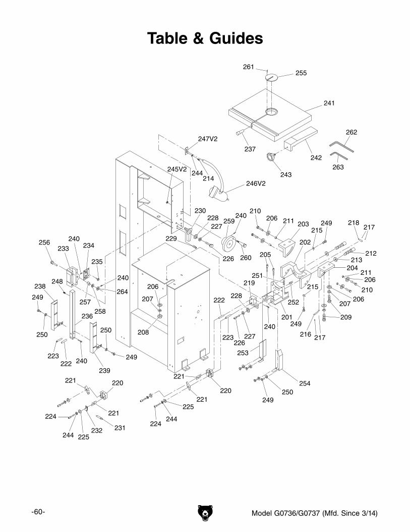
-60- Model G0736/G0737 (Mfd. Since 3/14)
Table & Guides
201
202
203
204
205
206
206
206
206
207207
208
209
210
210
211
211
212213
214244
215
249
216 217
217218249
215
219
220220
221
221
221
221
222
222
223
223
224224
225
225
226227
228
230
231232
233 234
235
236
237
238
239
240
240
240
241
242
262
263243
244
244
245V2
246V2
247V2
248
249
249
249
250250
250
251
252
253
254
255
256
257258
264
240
259240
260226
227228
229
261

Model G0736/G0737 (Mfd. Since 3/14) -61-
Table & Guides Parts ListREF PART # DESCRIPTION REF PART # DESCRIPTION201 P0736201 TRUNNION SUPPORT 233 P0736233 GUIDE POST BRACKET202 P0736202 TRUNNION 234 P0736234 GUIDE POST BRACKET COVER203 P0736203 LEFT TABLE BRACKET 235 PFH30M FLAT HD SCR M5-.8 X 8204 P0736204 RIGHT TABLE BRACKET 236 P0736236 GUIDE POST205 PCAP64M CAP SCREW M10-1.5 X 25 237 P0736237 TABLE PIN206 PW04M FLAT WASHER 10MM 238 P0736238 LEFT BLADE GUARD207 PLW06M LOCK WASHER 10MM 239 P0736239 RIGHT BLADE GUARD208 PN02M HEX NUT M10-1.5 240 PSS02M SET SCREW M6-1 X 6209 PB01M HEX BOLT M10-1.5 X 30 241 P0736241 TABLE210 PB116M HEX BOLT M10-1.5 X 45 242 P0736242 FENCE211 P0736211 BUSHING 243 P0736243 LOCK KNOB BOLT 1/2-12 X 1-1/2212 PCAP119M CAP SCREW M12-1.75 X 55 244 PLW03M LOCK WASHER 6MM213 PW06M FLAT WASHER 12MM 245V2 PN52 THIN HEX NUT 3/8-24214 PB02M HEX BOLT M6-1 X 12 246V2 P0736246V2 WORK LAMP ASSY 220V 3/8"-24 V2.06.12215 P0736215 POINTER 247V2 P0736247V2 LAMP BRACKET 3/8" SLOT V2.06.12216 P0736216 FORWARD-BACK TILT SCALE 248 PCAP26M CAP SCREW M6-1 X 12217 PRIV009M STEEL FLUTED RIVET 2 X 6MM 249 PS05M PHLP HD SCR M5-.8 X 8218 P0736218 LEFT-RIGHT TILT SCALE 250 PW02M FLAT WASHER 5MM219 P0736219 LOWER BLADE SUPPORT BRACKET 251 PCAP70M CAP SCREW M10-1.5 X 45220 P0736220 BLADE GUIDE BRACKET 252 PSS01M SET SCREW M6-1 X 10221 P0736221 BLADE GUIDE 253 P0736253 LOWER LEFT BLADE GUARD222 P0736222 GUIDE BRACKET SUPPORT ROD 254 P0736254 LOWER RIGHT BLADE GUARD223 P0736223 BLADE SUPPORT ROD 255 P0736255 TABLE INSERT224 PCAP06M CAP SCREW M6-1 X 25 256 P0736256 PINION SHAFT225 PW03M FLAT WASHER 6MM 257 P0736257 SHAFT SLEEVE226 PCAP13M CAP SCREW M8-1.25 X 30 258 PW28M FLAT WASHER 13MM227 PLW04M LOCK WASHER 8MM 259 P0736259 GUIDE POST HANDWHEEL228 PW01M FLAT WASHER 8MM 260 P0736260 HANDWHEEL HANDLE 3/8-16 X 3-1/4229 PSS06M SET SCREW M8-1.25 X 16 261 PRP18M ROLL PIN 4 X 12230 P0736230 GUIDE POST LOCK LEVER 262 PAW10M HEX WRENCH 10MM231 P0736231 AIR NOZZLE 263 PAW05M HEX WRENCH 5MM232 P0736232 NOZZLE CLAMP 264 P0736264 LOCK COLLAR
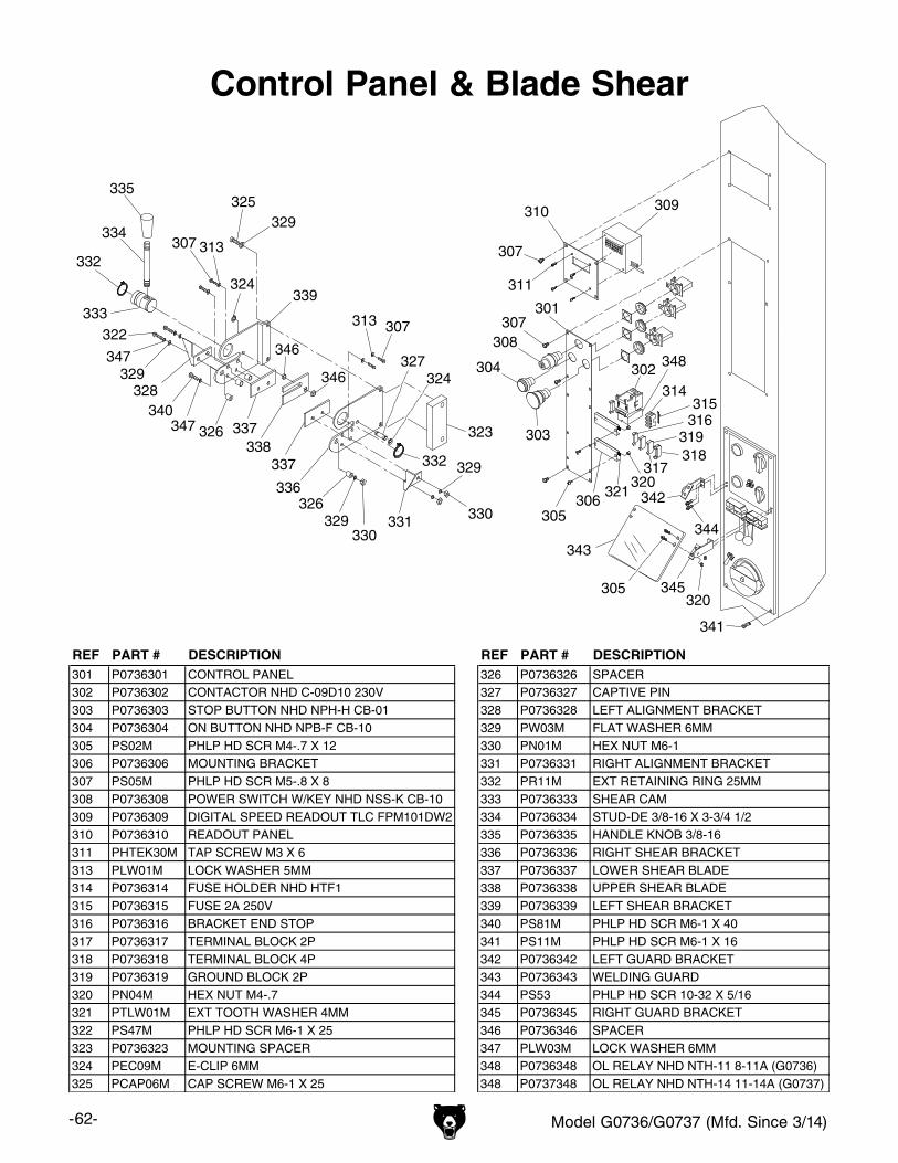
-62- Model G0736/G0737 (Mfd. Since 3/14)
Control Panel & Blade Shear
REF PART # DESCRIPTION REF PART # DESCRIPTION301 P0736301 CONTROL PANEL 326 P0736326 SPACER302 P0736302 CONTACTOR NHD C-09D10 230V 327 P0736327 CAPTIVE PIN303 P0736303 STOP BUTTON NHD NPH-H CB-01 328 P0736328 LEFT ALIGNMENT BRACKET304 P0736304 ON BUTTON NHD NPB-F CB-10 329 PW03M FLAT WASHER 6MM305 PS02M PHLP HD SCR M4-.7 X 12 330 PN01M HEX NUT M6-1306 P0736306 MOUNTING BRACKET 331 P0736331 RIGHT ALIGNMENT BRACKET307 PS05M PHLP HD SCR M5-.8 X 8 332 PR11M EXT RETAINING RING 25MM308 P0736308 POWER SWITCH W/KEY NHD NSS-K CB-10 333 P0736333 SHEAR CAM309 P0736309 DIGITAL SPEED READOUT TLC FPM101DW2 334 P0736334 STUD-DE 3/8-16 X 3-3/4 1/2310 P0736310 READOUT PANEL 335 P0736335 HANDLE KNOB 3/8-16311 PHTEK30M TAP SCREW M3 X 6 336 P0736336 RIGHT SHEAR BRACKET313 PLW01M LOCK WASHER 5MM 337 P0736337 LOWER SHEAR BLADE314 P0736314 FUSE HOLDER NHD HTF1 338 P0736338 UPPER SHEAR BLADE315 P0736315 FUSE 2A 250V 339 P0736339 LEFT SHEAR BRACKET316 P0736316 BRACKET END STOP 340 PS81M PHLP HD SCR M6-1 X 40317 P0736317 TERMINAL BLOCK 2P 341 PS11M PHLP HD SCR M6-1 X 16318 P0736318 TERMINAL BLOCK 4P 342 P0736342 LEFT GUARD BRACKET319 P0736319 GROUND BLOCK 2P 343 P0736343 WELDING GUARD320 PN04M HEX NUT M4-.7 344 PS53 PHLP HD SCR 10-32 X 5/16321 PTLW01M EXT TOOTH WASHER 4MM 345 P0736345 RIGHT GUARD BRACKET322 PS47M PHLP HD SCR M6-1 X 25 346 P0736346 SPACER323 P0736323 MOUNTING SPACER 347 PLW03M LOCK WASHER 6MM324 PEC09M E-CLIP 6MM 348 P0736348 OL RELAY NHD NTH-11 8-11A (G0736)325 PCAP06M CAP SCREW M6-1 X 25 348 P0737348 OL RELAY NHD NTH-14 11-14A (G0737)
301
302 348
303
304
305
305306
307
307
308307
307
309310
311
313
313
314315316
317318319
320
321320
322
323
324
324
325
326
326
327
328329
329
329
329
330
330331
332
332
333
334
335
336
337
337338
339
340
341
342
343344
345
346
346347
347
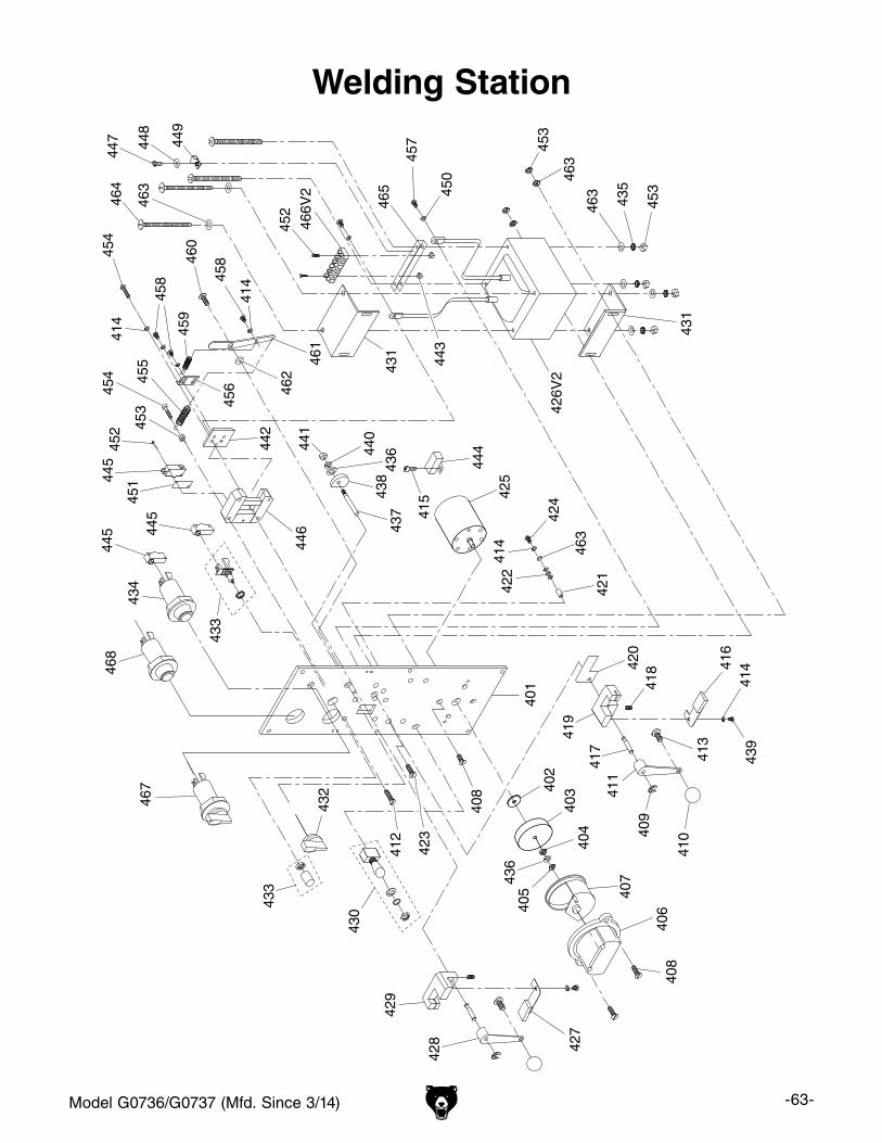
Model G0736/G0737 (Mfd. Since 3/14) -63-
Welding Station
401
402
403
404
405
436
406
407
408
408
409
410
411
412
413
414
415
416
417
418
419
420
421
422
423
42442
5
426V
242
7
428
429
430
431
431
432
433
434
435
436
437
438
439
440
441
442
443
444
445
445
433
445
446
447 44
8
449
450
451
452 45
3
453
452
453
454
454
414
414
455
456
457
458 45
8
459
460
461
462
463
463
463
463
414
464
465
466V
2
467
468

-64- Model G0736/G0737 (Mfd. Since 3/14)
Welding Station Parts ListREF PART # DESCRIPTION REF PART # DESCRIPTION401 P0736401 FRONT PANEL 435 P0736435 EXT TOOTH WASHER 5MM402 P0736402 SPACER 436 P0736436 LOCK WASHER 6MM403 P0736403 GRINDING WHEEL A60 65 X 16 X 7MM 437 P0736437 PRESSURE SHAFT404 P0736404 FLAT WASHER 6MM 438 P0736438 PRESSURE CAM405 P0736405 HEX NUT M6-1 439 P0736439 PHLP HD SCR M5-.8 X 6406 P0736406 GRINDER COVER 440 P0736440 FLAT WASHER 6MM407 P0736407 GRINDER GUARD 441 P0736441 HEX NUT M6-1408 P0736408 FLAT HD SCR 10-24 X 1/2 442 P0736442 PRESSURE GUIDE BLOCK409 P0736409 E-CLIP 6MM 443 P0736443 HEX NUT M3-.5410 P0736410 ROUND KNOB M6-1 444 P0736444 S CAPACITOR 2M 250V411 P0736411 RIGHT CLAMPING LEVER 445 P0736445 SWITCH DEFOND 125/250V412 P0736412 FLAT HD SCR M5-.8 X 8 446 P0736446 PRESSURE GUIDE CASTING413 P0736413 PHLP HD SCR M6-1 X 16 447 P0736447 PHLP HD SCR M4-.7 X 8414 P0736414 LOCK WASHER 5MM 448 P0736448 FLAT WASHER 4MM415 P0736415 PHLP HD SCR 10-24 X 1/4 449 P0736449 CORD CLAMP 1/2"416 P0736416 RIGHT MOVABLE CLAMP 450 P0736450 FLAT WASHER 5MM BRASS417 P0736417 ECCENTRIC SHAFT 451 P0736451 SWITCH INSULATOR418 P0736418 SET SCREW M6-1 X 6 452 P0736452 PHLP HD SCR M3-.5 X 20419 P0736419 RIGHT STATIONARY CLAMP 453 P0736453 HEX NUT M5-.8420 P0736420 CLAMP INSULATION PLATE 454 P0736454 CAP SCREW M5-.8 X 16421 P0736421 INSULATING SPACER 5MM 455 P0736455 LONG EXTENSION SPRING422 P0736422 INSULATING FLAT WASHER 5MM 456 P0736456 SPRING BRACKET423 P0736423 FLAT HD SCR M5-.8 X 12 457 P0736457 PHLP HD SCR M5-8 X 10 BRASS424 P0736424 CAP SCREW M5-.8 X 16 458 P0736458 PHLP HD SCR M5-.8 X 8425 P0736425 GRINDING MOTOR 1/8HP 110/220V 1PH 459 P0736459 SHORT EXTENSION SPRING426V2 P0736426V2 TRANSFORMER A174-0023 V2.03.14 460 P0736460 PHLP HD SCR 1/4-20 X 5/8427 P0736427 LEFT MOVABLE CLAMP 461 P0736461 TENSION ARM428 P0736428 LEFT CLAMPING LEVER 462 P0736462 TENSION ARM FLAT WASHER 1/4"429 P0736429 LEFT STATIONARY CLAMP 463 P0736463 FLAT WASHER 5MM430 P0736430 ON/OFF SWITCH R13-28F 464 P0736464 PHLP HD SCR M5-.8 X 65431 P0736431 TRANSFORMER MOUNTING BRACKET 465 P0736465 TERMINAL BLOCK BRACKET432 P0736432 PRESSURE ADJUSTMENT KNOB 466V2 P0736466V2 TRANSFORMER TERMINAL BLOCK V2.03.14433 P0736433 ANNEAL BUTTON ASSY DEFOND 15.1A 250V 467 P0736467 WELDER ON/OFF SWITCH NHD NCS-S4434 P0736434 WELD BUTTON ASSY YENOX YCL1G28 468 P0736468 POWER LAMP NHD NLD-22
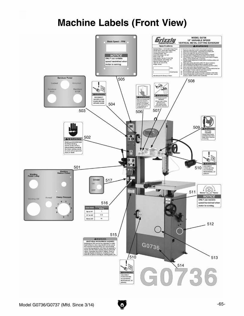
Model G0736/G0737 (Mfd. Since 3/14) -65-
501
502
503
504
505
506 507
508
509
510
510
511
512
513
514
515
516
517
Machine Labels (Front View)
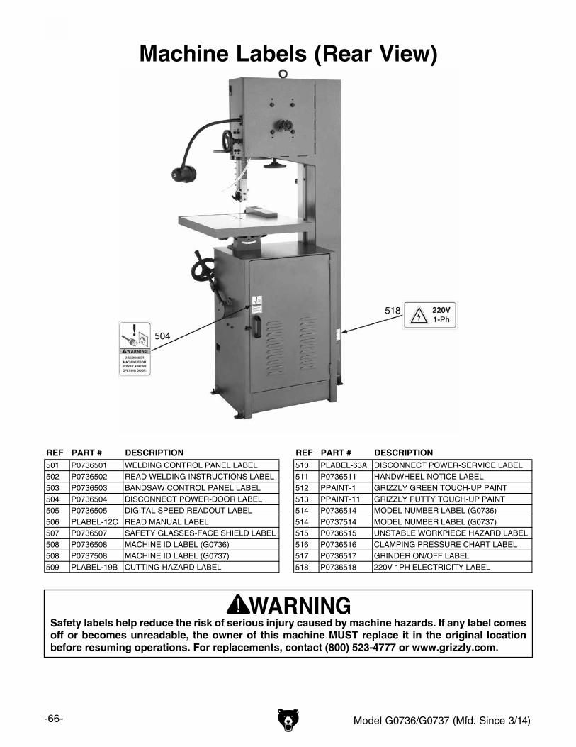
-66- Model G0736/G0737 (Mfd. Since 3/14)
518
504
Machine Labels (Rear View)
REF PART # DESCRIPTION REF PART # DESCRIPTION501 P0736501 WELDING CONTROL PANEL LABEL 510 PLABEL-63A DISCONNECT POWER-SERVICE LABEL502 P0736502 READ WELDING INSTRUCTIONS LABEL 511 P0736511 HANDWHEEL NOTICE LABEL503 P0736503 BANDSAW CONTROL PANEL LABEL 512 PPAINT-1 GRIZZLY GREEN TOUCH-UP PAINT504 P0736504 DISCONNECT POWER-DOOR LABEL 513 PPAINT-11 GRIZZLY PUTTY TOUCH-UP PAINT505 P0736505 DIGITAL SPEED READOUT LABEL 514 P0736514 MODEL NUMBER LABEL (G0736)506 PLABEL-12C READ MANUAL LABEL 514 P0737514 MODEL NUMBER LABEL (G0737)507 P0736507 SAFETY GLASSES-FACE SHIELD LABEL 515 P0736515 UNSTABLE WORKPIECE HAZARD LABEL508 P0736508 MACHINE ID LABEL (G0736) 516 P0736516 CLAMPING PRESSURE CHART LABEL508 P0737508 MACHINE ID LABEL (G0737) 517 P0736517 GRINDER ON/OFF LABEL509 PLABEL-19B CUTTING HAZARD LABEL 518 P0736518 220V 1PH ELECTRICITY LABEL
Safety labels help reduce the risk of serious injury caused by machine hazards. If any label comes off or becomes unreadable, the owner of this machine MUST replace it in the original location before resuming operations. For replacements, contact (800) 523-4777 or www.grizzly.com.

CU
T A
LON
G D
OT
TE
D L
INE
Name _____________________________________________________________________________
Street _____________________________________________________________________________
City _______________________ State _________________________ Zip _____________________
Phone # ____________________ Email _________________________________________________
Model # ____________________ Order # _______________________ Serial # __________________
WARRANTY CARD
The following information is given on a voluntary basis. It will be used for marketing purposes to help us develop better products and services. Of course, all information is strictly confidential.
1. How did you learn about us? ____ Advertisement ____ Friend ____ Catalog ____ Card Deck ____ Website ____ Other:
2. Which of the following magazines do you subscribe to?
3. What is your annual household income? ____ $20,000-$29,000 ____ $30,000-$39,000 ____ $40,000-$49,000 ____ $50,000-$59,000 ____ $60,000-$69,000 ____ $70,000+
4. What is your age group? ____ 20-29 ____ 30-39 ____ 40-49 ____ 50-59 ____ 60-69 ____ 70+
5. How long have you been a woodworker/metalworker? ____ 0-2 Years ____ 2-8 Years ____ 8-20 Years ____20+ Years
6. How many of your machines or tools are Grizzly? ____ 0-2 ____ 3-5 ____ 6-9 ____10+
7. Do you think your machine represents a good value? _____Yes _____No
8. Would you recommend Grizzly Industrial to a friend? _____Yes _____No
9. Would you allow us to use your name as a reference for Grizzly customers in your area? Note: We never use names more than 3 times. _____Yes _____No
10. Comments: _____________________________________________________________________
_________________________________________________________________________________
_________________________________________________________________________________
_________________________________________________________________________________
____ Cabinetmaker & FDM____ Family Handyman____ Hand Loader____ Handy____ Home Shop Machinist____ Journal of Light Cont.____ Live Steam____ Model Airplane News____ Old House Journal____ Popular Mechanics
____ Popular Science____ Popular Woodworking____ Precision Shooter____ Projects in Metal____ RC Modeler____ Rifle____ Shop Notes____ Shotgun News____ Today’s Homeowner____ Wood
____ Wooden Boat____ Woodshop News____ Woodsmith____ Woodwork____ Woodworker West____ Woodworker’s Journal____ Other:

TAPE ALONG EDGES--PLEASE DO NOT STAPLE
FOLD ALONG DOTTED LINE
FOLD ALONG DOTTED LINE
GRIZZLY INDUSTRIAL, INC.P.O. BOX 2069BELLINGHAM, WA 98227-2069
PlaceStampHere
Name_______________________________
Street_______________________________
City______________State______Zip______
Send a Grizzly Catalog to a friend:

WARRANTY & RETURNSGrizzly Industrial, Inc. warrants every product it sells for a period of 1 year to the original purchaser from the date of purchase. This warranty does not apply to defects due directly or indirectly to misuse, abuse, negligence, accidents, repairs or alterations or lack of maintenance. This is Grizzly’s sole written warranty and any and all warranties that may be implied by law, including any merchantability or fitness, for any par-ticular purpose, are hereby limited to the duration of this written warranty. We do not warrant or represent that the merchandise complies with the provisions of any law or acts unless the manufacturer so warrants. In no event shall Grizzly’s liability under this warranty exceed the purchase price paid for the product and any legal actions brought against Grizzly shall be tried in the State of Washington, County of Whatcom.
We shall in no event be liable for death, injuries to persons or property or for incidental, contingent, special, or consequential damages arising from the use of our products.
To take advantage of this warranty, contact us by mail or phone and give us all the details. We will then issue you a “Return Number,’’ which must be clearly posted on the outside as well as the inside of the carton. We will not accept any item back without this number. Proof of purchase must accompany the merchandise.
The manufacturers reserve the right to change specifications at any time because they constantly strive to achieve better quality equipment. We make every effort to ensure that our products meet high quality and durability standards and we hope you never need to use this warranty.
Please feel free to write or call us if you have any questions about the machine or the manual.
Thank you again for your business and continued support. We hope to serve you again soon.


![Welcome [cdn0.vox-cdn.com]](https://img.pdfslide.us/doc/110x75/61760ba9b147146c9c747c8b/welcome-cdn0vox-cdncom.jpg)