Embed Size (px)
Citation preview

MODEL E-04 ELT
INSTALLATION MANUAL
OPERATION MANUAL IMPORTANT VISIT OUR WEBSITE WWW.ACKAVIONICS.COM FOR THE LATEST SERVICE BULLETINS AND INSTALLATION INFORMATION BEFORE STARTING THE INSTALLATION.
THE CONDITIONS AND TESTS REQUIRED FOR TSO APPROVAL OF THIS ARTICLE ARE MINIMUM PERFORMANCE STANDARDS. IT IS THE RESPONSIBILITY OF THOSE DESIRING TO INSTALL THIS ARTICLE ON A SPECIFIC TYPE OR CLASS OF AIRCRAFT TO DETERMINE THAT THE AIRCRAFT INSTALLATION CONDITIONS ARE WITHIN THE TSO STANDARDS. THE ARTICLE MAY BE INSTALLED ONLY IF FURTHER EVALUATION BY THE APPLICANT DOCUMENTS AN ACCEPTABLE INSTALLATION AND IT IS APPROVED BY THE ADMINISTRATOR.
P/N E04M REV DATE 12/02/2015 Rev 1.8 PRINTED IN THE USA
APPROVALS
FAA /TRANSPORT CANADA TSO C-126b TSO C-142a TSO C-91a
EASA ETSO 2C126 ETSO 2C91a ETSO C142a
COSPAS/SARSAT T.007
INDUSTRY CANADA 1863A-E04AF
Brazil ANAC ANTEL
TABLE OF CONTENTS
Section 1 406 MHz ELT overview Section 2 ELT installation Section 3 Antenna installation Section 4 Remote control installation Section 5 Audio alert indicator installation Section 6 GPS interface installation Section 7 Final installation and checkout Section 8 Registration Section 9 Operation and self test Section 10 Periodic maintenance / Continuing airworthiness Section 11 Lithium battery replacement Section 12 Programming Section 13 Warranty procedure Section 14 Canadian maintenance requirements Section 15 Specifications Section 16 Major parts Section 17 Environmental qualifications DO-160F/ED-14F Section 18 RS 232 data formats / Installation notes Section 19 Trouble shooting / Miscellaneous notes
SECTION 1 406 MHz ELT OVERVIEW The model E-04 121.5/406 MHz ELT is designed for use in aircraft used for general and commercial aviation. Older generation ELT’s were very limited in their ability to rapidly locate, and identify a downed aircraft. Often it took several passes of the orbiting satellites to get an approximate fix on a downed aircraft. The older generation ELT’s gave rescuers no information on type of aircraft, owner/operator, or contact information. The new generation 406 MHz ELT’s provide much better, and faster location accuracy. Along with providing information to search and rescue organizations about the aircraft type, ownership, and emergency contact information. Location accuracy with older generation ELT’s was limited to about a 15 - 20 mile radius, and could take several hours to provide accurate location data. For new generation 406 MHz ELT’s without GPS position information, the average time to process, and identify the aircraft location is 1-2 hours, with a search radius of about 2 miles or less. With GPS information, the time to locate the aircraft position is 10 minutes or less, with an accuracy of about 300 feet. The model E-04 ELT may be installed without interfacing it to the aircraft GPS system, however we strongly recommend that when available the GPS data be supplied to the ELT. For aircraft which do not have GPS data available, the unit can be interfaced with a low cost GPS data receiver, such as the Garmin GPS 18PC which is available for less than $75.00. (Note: these receivers require a 5V supply. One model has a cigarette lighter plug with a built in regulator, or you can use a 5V switching power supply, such as Digi-Key P/N 811-1116-ND) You must register this beacon before activating it. Failure to do so can result in monetary fines, and other sanctions. See section 8 for registration instructions. You must update your registration every two years.
SECTION 2 ELT INSTALLATION Several problems associated with previous TSO C-91, and C-91a ELT installations, is the result of poorly chosen mounting locations. Generally the most suitable location for fixed wing aircraft, is to position the ELT transmitter in the fuselage as far aft as possible. Anten-na location, and accessibility for maintenance, are factors that should be considered when choosing a mounting location. The ELT must be mounted with the arrow printed on the battery case pointing in the direction of flight. The ELT should be mounted with it’s longi-tudinal axis aligned within 10 degrees of the longitudinal axis of the aircraft fuselage. Avoid mounting the ELT near sources of strong EMI/RFI radiation. RTCA document DO-204 paragraph 3.1.8. prescribes the mounting requirements which must be met when installing this ELT, these requirements are as follows:
The ELT shall be mounted to primary load-carrying structures such as trusses, bulkheads, longerons, spars, or floor beams. (not aircraft skin) The mounts shall have a maximum static local deflection no greater than 2.5mm (0.1 inch) when a force of 450 newton's (100 lbs.) is applied to the mount in the most flexible direction. Deflection measurements shall
2
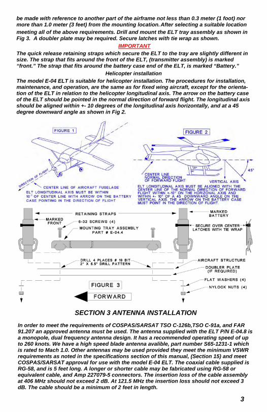
be made with reference to another part of the airframe not less than 0.3 meter (1 foot) nor more than 1.0 meter (3 feet) from the mounting location. After selecting a suitable location meeting all of the above requirements. Drill and mount the ELT tray assembly as shown in Fig 3. A doubler plate may be required. Secure latches with tie wrap as shown.
IMPORTANT The quick release retaining straps which secure the ELT to the tray are slightly different in size. The strap that fits around the front of the ELT, (transmitter assembly) is marked “front.” The strap that fits around the battery case end of the ELT, is marked “Battery.”
Helicopter installation The model E-04 ELT is suitable for helicopter installation. The procedures for installation, maintenance, and operation, are the same as for fixed wing aircraft, except for the orienta-tion of the ELT in relation to the helicopter longitudinal axis. The arrow on the battery case of the ELT should be pointed in the normal direction of forward flight. The longitudinal axis should be aligned within +- 10 degrees of the longitudinal axis horizontally, and at a 45 degree downward angle as shown in Fig 2.
3
SECTION 3 ANTENNA INSTALLATION
In order to meet the requirements of COSPAS/SARSAT TSO C-126b,TSO C-91a, and FAR 91.207 an approved antenna must be used. The antenna supplied with the ELT P/N E-04.8 is a monopole, dual frequency antenna design. It has a recommended operating speed of up to 260 knots. We have a high speed blade antenna avalible, part number S65-1231-1 which is rated to Mach 1.0. Other antennas may be used provided they meet the minimum VSWR requirements as noted in the specifications section of this manual, (Section 15) and meet COSPAS/SARSAT approval for use with the model E-04 ELT. The coaxial cable supplied is RG-58, and is 5 feet long. A longer or shorter cable may be fabricated using RG-58 or equivalent cable, and Amp 227079-5 connectors. The insertion loss of the cable assembly at 406 MHz should not exceed 2 dB. At 121.5 MHz the insertion loss should not exceed 3 dB. The cable should be a minimum of 2 feet in length.
The antenna may be mounted internally in composite construction, and tubular fabric covered aircraft, as long as the fabric or composite material is of a non conductive nature. The antenna must be mounted externally, on airframes of metallic construction. The antenna should be mounted as close to the ELT transmitter as practical. The coaxial cable connecting the antenna to the ELT transmitter, should not run in close proximity to comm radio coaxial cables, and should avoid crossing aircraft production breaks. (i.e. Riveted fuselage sections) The antenna must be mounted within 30 degrees of vertical, when the aircraft is in normal flight attitude. The installed antenna must be able to withstand a static load of 100 (one hundred) times it’s weight (13 lbs.) applied to the base of the antenna, along the longitudinal axis of the aircraft. The antenna should be mounted a minimum dis-tance of three feet (1 meter) from any vertically polarized communication antennas. (i.e. Antennas radiating in the 118-137 MHz band.)
MODEL E-04.8 WHIP ANTENNA
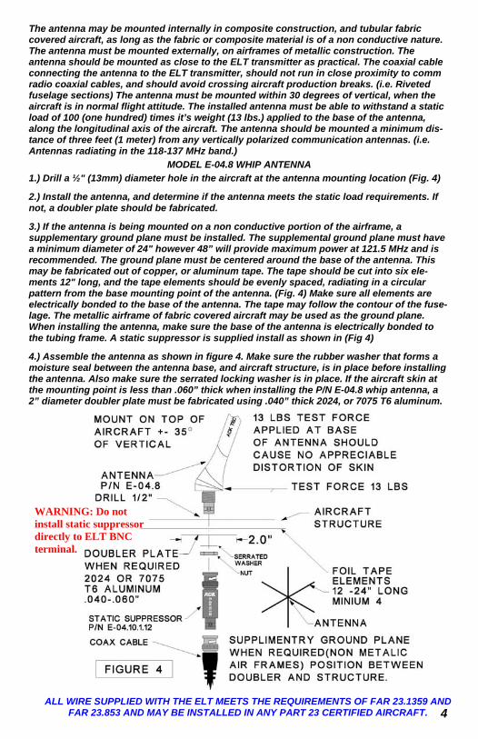
1.) Drill a ½" (13mm) diameter hole in the aircraft at the antenna mounting location (Fig. 4)
2.) Install the antenna, and determine if the antenna meets the static load requirements. If not, a doubler plate should be fabricated.
3.) If the antenna is being mounted on a non conductive portion of the airframe, a supplementary ground plane must be installed. The supplemental ground plane must have a minimum diameter of 24" however 48” will provide maximum power at 121.5 MHz and is recommended. The ground plane must be centered around the base of the antenna. This may be fabricated out of copper, or aluminum tape. The tape should be cut into six ele-ments 12" long, and the tape elements should be evenly spaced, radiating in a circular pattern from the base mounting point of the antenna. (Fig. 4) Make sure all elements are electrically bonded to the base of the antenna. The tape may follow the contour of the fuse-lage. The metallic airframe of fabric covered aircraft may be used as the ground plane. When installing the antenna, make sure the base of the antenna is electrically bonded to the tubing frame. A static suppressor is supplied install as shown in (Fig 4)
4.) Assemble the antenna as shown in figure 4. Make sure the rubber washer that forms a moisture seal between the antenna base, and aircraft structure, is in place before installing the antenna. Also make sure the serrated locking washer is in place. If the aircraft skin at the mounting point is less than .060” thick when installing the P/N E-04.8 whip antenna, a 2” diameter doubler plate must be fabricated using .040” thick 2024, or 7075 T6 aluminum.
4 ALL WIRE SUPPLIED WITH THE ELT MEETS THE REQUIREMENTS OF FAR 23.1359 AND
FAR 23.853 AND MAY BE INSTALLED IN ANY PART 23 CERTIFIED AIRCRAFT.
WARNING: Do not install static suppressor directly to ELT BNC terminal.
SECTION 4 REMOTE CONTROL INSTALLATION
IMPORTANT YOU MUST INSTALL A BATTERY IN THE REMOTE.
The remote control panel indicator (RCPI) P/N E-04.5 is designed to be powered by a single Duracell PX28L 6 volt Lithium battery, or equivalent. Alkaline batteries may be used such as Eveready A 544, or equivalent. Under normal operating conditions, the Lithium battery must be replaced every 10 years. The alkaline batteries must be replaced every 5 years. If the ELT is activated for an unknown period of time, the battery must be replaced. Equivalent cross reference batteries from other manufacturers are acceptable for use in the remote control.
To install, or replace the RCPI battery follow these steps:
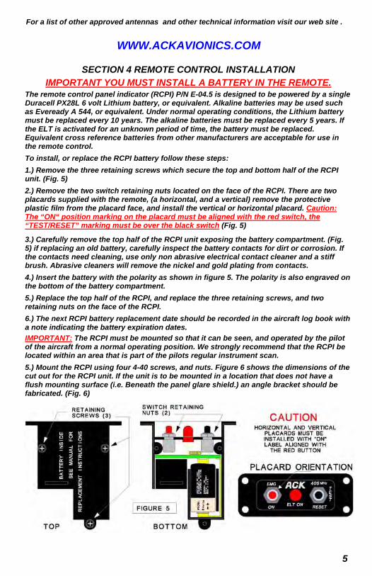
1.) Remove the three retaining screws which secure the top and bottom half of the RCPI unit. (Fig. 5)
2.) Remove the two switch retaining nuts located on the face of the RCPI. There are two placards supplied with the remote, (a horizontal, and a vertical) remove the protective plastic film from the placard face, and install the vertical or horizontal placard. Caution: The “ON“ position marking on the placard must be aligned with the red switch, the “TEST/RESET” marking must be over the black switch (Fig. 5)
3.) Carefully remove the top half of the RCPI unit exposing the battery compartment. (Fig. 5) if replacing an old battery, carefully inspect the battery contacts for dirt or corrosion. If the contacts need cleaning, use only non abrasive electrical contact cleaner and a stiff brush. Abrasive cleaners will remove the nickel and gold plating from contacts.
4.) Insert the battery with the polarity as shown in figure 5. The polarity is also engraved on the bottom of the battery compartment.
5.) Replace the top half of the RCPI, and replace the three retaining screws, and two retaining nuts on the face of the RCPI.
6.) The next RCPI battery replacement date should be recorded in the aircraft log book with a note indicating the battery expiration dates.
IMPORTANT: The RCPI must be mounted so that it can be seen, and operated by the pilot of the aircraft from a normal operating position. We strongly recommend that the RCPI be located within an area that is part of the pilots regular instrument scan.
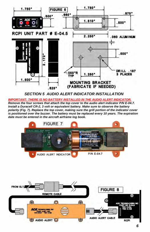
5.) Mount the RCPI using four 4-40 screws, and nuts. Figure 6 shows the dimensions of the cut out for the RCPI unit. If the unit is to be mounted in a location that does not have a flush mounting surface (i.e. Beneath the panel glare shield.) an angle bracket should be fabricated. (Fig. 6)
5
For a list of other approved antennas and other technical information visit our web site .
WWW.ACKAVIONICS.COM
6
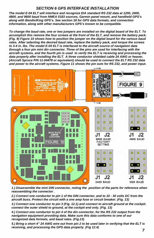
SECTION 5 AUDIO ALERT INDICATOR INSTALLATION
IMPORTANT: THERE IS NO BATTERY INSTALLED IN THE AUDIO ALERT INDICATOR. Remove the four screws that attach the top cover to the audio alert indicator P/N E-04.7. Install a Duracell CR-2, 3 volt or equivalent battery. Make sure to observe the battery polarity (Fig. 7). Replace the top cover, making sure the grill portion of the indicator cover is positioned over the buzzer. The battery must be replaced every 10 years. The expiration date must be entered in the aircraft airframe log book.
SECTION 6 GPS INTERFACE INSTALLATION
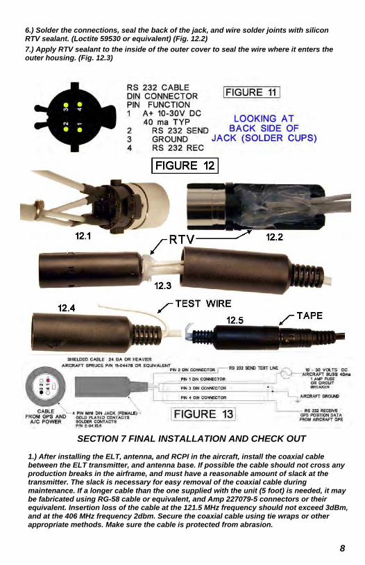
The model E-04 ELT will interface and recognize EIA standard RS 232 data at 1200, 2400, 4800, and 9600 baud from NMEA 0183 sources, Garmin panel mount, and handheld GPS’s along with Bendix/King GPS’s. See section 18 for GPS data formats, and connection information, along with other manufacturers GPS’s known to be compatible.
7
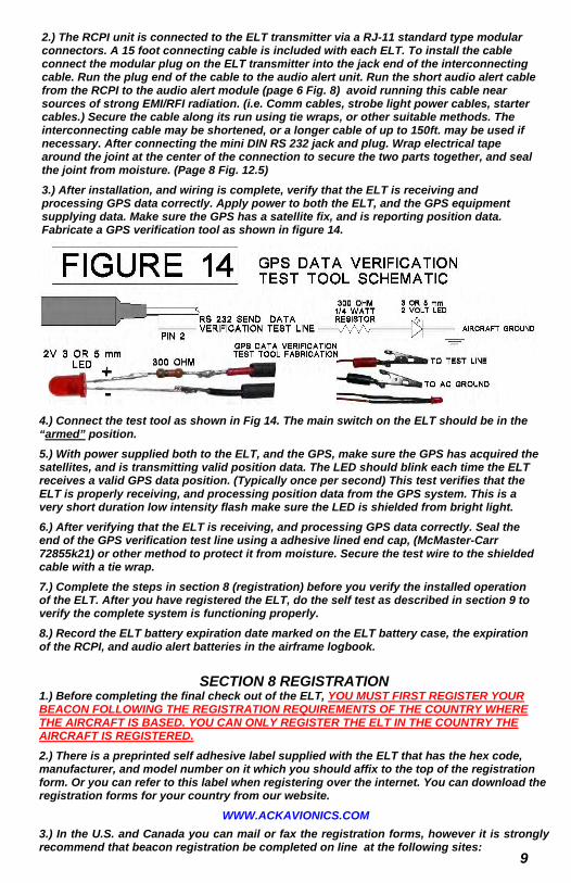
To change the baud rate, one or two jumpers are installed on the digital board of the ELT. To accomplish this remove the four screws at the front of the ELT, and remove the battery pack. (Fig. 9) Figure 10 shows how to position the jumper on the digital board for the various baud rates. After selecting the desired baud rate, replace the battery pack, and torque the screws to 3-4 in. lbs. The model E-04 ELT is interfaced to the aircraft source of navigation data through a four pin mini din connector. Three of the pins are used for interfacing with the aircraft systems, and the fourth pin is used to verify the ELT is receiving and processing the data properly after installing the ELT. A three conductor shielded cable 24 AWG or heaver, (Aircraft Spruce P/N 11-04478 or equivalent) should be used to connect the ELT RS 232 data and power to the aircraft systems. Figure 11 shows the pin outs for RS 232, and power input.
1.) Disassemble the mini DIN connector, noting the position of the parts for reference when reassembling the connector .
2.) Connect one conductor to pin 1 of the DIN connector, and to 10 - 30 volts DC from the aircraft buss. Protect the circuit with a one amp fuse or circuit breaker. (Fig. 13)
3.) Connect one conductor to pin 3 (Fig. 12.1) and connect to aircraft ground at the cockpit. connect the outer shield to ground, at the cockpit end only. (Fig. 13)
4.) Connect one conductor to pin 4 of the din connector, for the RS 232 output from the navigation equipment providing data. Make sure this data conforms to one of our recognized data formats, and baud rates. (Fig.13)
5.) Bring a short 4” 24 AWG wire out from pin 2 to be used later in verifying that the ELT is receiving, and processing the GPS data properly. (Fig 12.4)
6.) Solder the connections, seal the back of the jack, and wire solder joints with silicon RTV sealant. (Loctite 59530 or equivalent) (Fig. 12.2)
7.) Apply RTV sealant to the inside of the outer cover to seal the wire where it enters the outer housing. (Fig. 12.3)
8
SECTION 7 FINAL INSTALLATION AND CHECK OUT
1.) After installing the ELT, antenna, and RCPI in the aircraft, install the coaxial cable between the ELT transmitter, and antenna base. If possible the cable should not cross any production breaks in the airframe, and must have a reasonable amount of slack at the transmitter. The slack is necessary for easy removal of the coaxial cable during maintenance. If a longer cable than the one supplied with the unit (5 foot) is needed, it may be fabricated using RG-58 cable or equivalent, and Amp 227079-5 connectors or their equivalent. Insertion loss of the cable at the 121.5 MHz frequency should not exceed 3dBm, and at the 406 MHz frequency 2dbm. Secure the coaxial cable using tie wraps or other appropriate methods. Make sure the cable is protected from abrasion.
9
2.) The RCPI unit is connected to the ELT transmitter via a RJ-11 standard type modular connectors. A 15 foot connecting cable is included with each ELT. To install the cable connect the modular plug on the ELT transmitter into the jack end of the interconnecting cable. Run the plug end of the cable to the audio alert unit. Run the short audio alert cable from the RCPI to the audio alert module (page 6 Fig. 8) avoid running this cable near sources of strong EMI/RFI radiation. (i.e. Comm cables, strobe light power cables, starter cables.) Secure the cable along its run using tie wraps, or other suitable methods. The interconnecting cable may be shortened, or a longer cable of up to 150ft. may be used if necessary. After connecting the mini DIN RS 232 jack and plug. Wrap electrical tape around the joint at the center of the connection to secure the two parts together, and seal the joint from moisture. (Page 8 Fig. 12.5)
3.) After installation, and wiring is complete, verify that the ELT is receiving and processing GPS data correctly. Apply power to both the ELT, and the GPS equipment supplying data. Make sure the GPS has a satellite fix, and is reporting position data. Fabricate a GPS verification tool as shown in figure 14.
4.) Connect the test tool as shown in Fig 14. The main switch on the ELT should be in the “armed” position.
5.) With power supplied both to the ELT, and the GPS, make sure the GPS has acquired the satellites, and is transmitting valid position data. The LED should blink each time the ELT receives a valid GPS data position. (Typically once per second) This test verifies that the ELT is properly receiving, and processing position data from the GPS system. This is a very short duration low intensity flash make sure the LED is shielded from bright light.
6.) After verifying that the ELT is receiving, and processing GPS data correctly. Seal the end of the GPS verification test line using a adhesive lined end cap, (McMaster-Carr 72855k21) or other method to protect it from moisture. Secure the test wire to the shielded cable with a tie wrap.
7.) Complete the steps in section 8 (registration) before you verify the installed operation of the ELT. After you have registered the ELT, do the self test as described in section 9 to verify the complete system is functioning properly.
8.) Record the ELT battery expiration date marked on the ELT battery case, the expiration of the RCPI, and audio alert batteries in the airframe logbook.
SECTION 8 REGISTRATION 1.) Before completing the final check out of the ELT, YOU MUST FIRST REGISTER YOUR BEACON FOLLOWING THE REGISTRATION REQUIREMENTS OF THE COUNTRY WHERE THE AIRCRAFT IS BASED. YOU CAN ONLY REGISTER THE ELT IN THE COUNTRY THE AIRCRAFT IS REGISTERED.
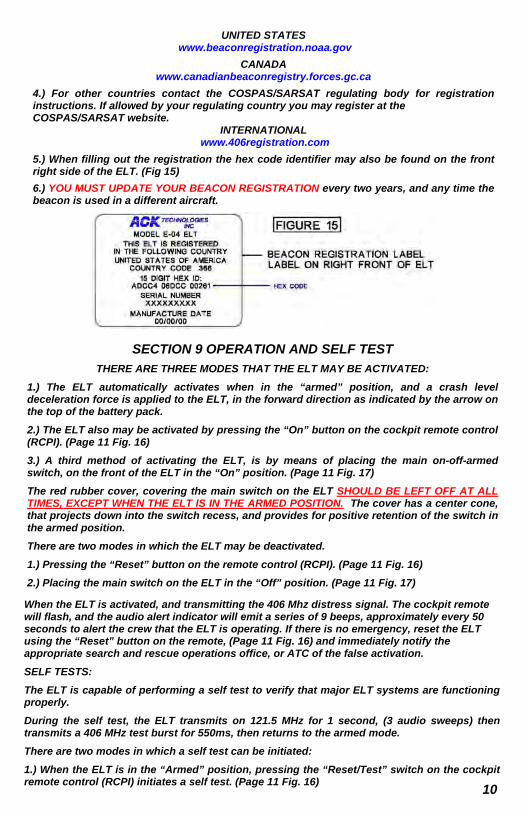
2.) There is a preprinted self adhesive label supplied with the ELT that has the hex code, manufacturer, and model number on it which you should affix to the top of the registration form. Or you can refer to this label when registering over the internet. You can download the registration forms for your country from our website.
WWW.ACKAVIONICS.COM
3.) In the U.S. and Canada you can mail or fax the registration forms, however it is strongly recommend that beacon registration be completed on line at the following sites:
10
UNITED STATES www.beaconregistration.noaa.gov
CANADA www.canadianbeaconregistry.forces.gc.ca
4.) For other countries contact the COSPAS/SARSAT regulating body for registration instructions. If allowed by your regulating country you may register at the COSPAS/SARSAT website.
INTERNATIONAL www.406registration.com
5.) When filling out the registration the hex code identifier may also be found on the front right side of the ELT. (Fig 15)
6.) YOU MUST UPDATE YOUR BEACON REGISTRATION every two years, and any time the beacon is used in a different aircraft.
SECTION 9 OPERATION AND SELF TEST
THERE ARE THREE MODES THAT THE ELT MAY BE ACTIVATED:
1.) The ELT automatically activates when in the “armed” position, and a crash level deceleration force is applied to the ELT, in the forward direction as indicated by the arrow on the top of the battery pack.
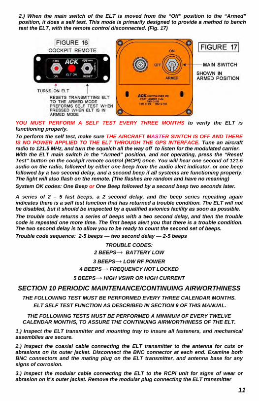
2.) The ELT also may be activated by pressing the “On” button on the cockpit remote control (RCPI). (Page 11 Fig. 16)
3.) A third method of activating the ELT, is by means of placing the main on-off-armed switch, on the front of the ELT in the “On” position. (Page 11 Fig. 17)
The red rubber cover, covering the main switch on the ELT SHOULD BE LEFT OFF AT ALL TIMES, EXCEPT WHEN THE ELT IS IN THE ARMED POSITION. The cover has a center cone, that projects down into the switch recess, and provides for positive retention of the switch in the armed position.
There are two modes in which the ELT may be deactivated.
1.) Pressing the “Reset” button on the remote control (RCPI). (Page 11 Fig. 16)
2.) Placing the main switch on the ELT in the “Off” position. (Page 11 Fig. 17)
When the ELT is activated, and transmitting the 406 Mhz distress signal. The cockpit remote will flash, and the audio alert indicator will emit a series of 9 beeps, approximately every 50 seconds to alert the crew that the ELT is operating. If there is no emergency, reset the ELT using the “Reset” button on the remote, (Page 11 Fig. 16) and immediately notify the appropriate search and rescue operations office, or ATC of the false activation.
SELF TESTS:
The ELT is capable of performing a self test to verify that major ELT systems are functioning properly.
During the self test, the ELT transmits on 121.5 MHz for 1 second, (3 audio sweeps) then transmits a 406 MHz test burst for 550ms, then returns to the armed mode.
There are two modes in which a self test can be initiated:
1.) When the ELT is in the “Armed” position, pressing the “Reset/Test” switch on the cockpit remote control (RCPI) initiates a self test. (Page 11 Fig. 16)
11
2.) When the main switch of the ELT is moved from the “Off” position to the “Armed” position, it does a self test. This mode is primarily designed to provide a method to bench test the ELT, with the remote control disconnected. (Fig. 17)
YOU MUST PERFORM A SELF TEST EVERY THREE MONTHS to verify the ELT is functioning properly.
To perform the self test, make sure THE AIRCRAFT MASTER SWITCH IS OFF AND THERE IS NO POWER APPLIED TO THE ELT THROUGH THE GPS INTERFACE. Tune an aircraft radio to 121.5 MHz, and turn the squelch all the way off to listen for the modulated carrier. With the ELT main switch in the “Armed” position, and not operating, press the “Reset/Test” button on the cockpit remote control (RCPI) once. You will hear one second of 121.5 audio on the radio, followed by either one beep from the audio alert indicator, or one beep followed by a two second delay, and a second beep if all systems are functioning properly. The light will also flash on the remote. (The flashes are random and have no meaning)
System OK codes: One Beep or One Beep followed by a second beep two seconds later.
A series of 2 – 5 fast beeps, a 2 second delay, and the beep series repeating again indicates there is a self test function that has returned a trouble condition. The ELT will not be disabled, but it should be inspected by a qualified avionics facility as soon as possible.
The trouble code returns a series of beeps with a two second delay, and then the trouble code is repeated one more time. The first beeps alert you that there is a trouble condition. The two second delay is to allow you to be ready to count the second set of beeps.
Trouble code sequence: 2-5 beeps — two second delay — 2-5 beeps
TROUBLE CODES:
2 BEEPS→ BATTERY LOW
3 BEEPS→ LOW RF POWER
4 BEEPS→ FREQUENCY NOT LOCKED
5 BEEPS→ HIGH VSWR OR HIGH CURRENT
SECTION 10 PERIODIC MAINTENANCE/CONTINUING AIRWORTHINESS
THE FOLLOWING TEST MUST BE PERFORMED EVERY THREE CALENDAR MONTHS.
ELT SELF TEST FUNCTION AS DESCRIBED IN SECTION 9 OF THIS MANUAL.
THE FOLLOWING TESTS MUST BE PERFORMED A MINIMUM OF EVERY TWELVE CALENDAR MONTHS, TO ASSURE THE CONTINUING AIRWORTHINESS OF THE ELT.
1.) Inspect the ELT transmitter and mounting tray to insure all fasteners, and mechanical assemblies are secure.
2.) Inspect the coaxial cable connecting the ELT transmitter to the antenna for cuts or abrasions on its outer jacket. Disconnect the BNC connector at each end. Examine both BNC connectors and the mating plug on the ELT transmitter, and antenna base for any signs of corrosion.
3.) Inspect the modular cable connecting the ELT to the RCPI unit for signs of wear or abrasion on it’s outer jacket. Remove the modular plug connecting the ELT transmitter
to the connecting cable, and inspect the jack and plug assembly for corrosion.
4.) If a GPS is interfaced to the ELT, inspect the modular cable connecting the ELT to the GPS unit for signs of wear or abrasion on its outer jacket. Remove the modular plug connecting the ELT transmitter to the GPS and inspect the jack and plug assembly for corrosion.
5.) Check the expiration date of the RCPI battery and audio alert battery in the aircraft log book. Check the expiration date of the battery pack and replace if necessary.
6.) Leave the ELT in the “Armed” position, then remove the ELT from the aircraft, and perform a G switch test as follows:
This test should be conducted between the hour, and 5 minutes after the hour per FCC requirements. Tune an aircraft radio, or hand held aircraft radio to 121.5 MHz. The radio should be in close proximity to the area where you will conduct the test.
TURN THE SQUELCH CONTROL ALL THE WAY DOWN, OR OFF. You should be hearing white noise on the radio. If switching the main switch from the “Off” to the “Armed” position wait at least 15 seconds before performing this test. While in the “Armed” position, hold the ELT at your waist with the arrow printed on the battery case facing away from you. Move the ELT rapidly away from your waist. When the ELT reaches the full extent of your arm, retract it back to your waist as fast as possible. You should hear the 121.5 MHz sweep tone in the radio. AS SOON AS YOU HEAR THE TONE, IMMEDIATELY TURN THE MAIN SWITCH ON THE ELT TO THE “OFF” POSITION.
The ELT when activated transmits on 121.5 MHz for approximately 50 seconds before a 406 MHz burst is sent to the satellites. This is a live burst which will immediately notify the COSPAS/SARSAT system that there is an emergency. IT IS IMPERATIVE THAT YOU DO NOT ALLOW AN ACTIVATED ELT, TO TRANSMIT FOR MORE THAN 30 SECONDS DURING G SWITCH TESTING. 3
7.) Reinstall the ELT, make sure the cables are secured, and properly connected. Make sure to seal the din connector if the ELT is connected to the aircraft GPS. (Page 8 Fig. 12.5) Place the main switch in the “Armed” position, and install the rubber cover over the main switch opening. 3
8.) Perform the self test described in section 9 to verify proper operation.
BATTERY AND ELT DOT/ IATA SHIPPING INFORMATION
The ELT with the battery attached is a DOT/IATA class 9 hazmat material under the category of life saving appliances not self inflating UN 3072. THERE ARE NO AIR SHIPMENT RESTRICTIONS FOR SUCH DEVICES, AND THEY MAY BE SHIPPED IN ANY QUANTITY IN PASSENGER CARRYING, OR TRANSPORT AIRCRAFT. The original ACK ELT shipping box complies with (UN) United Nations packaging specifications. 12
SECTION 11 E-04.0 LITHIUM BATTERY REPLACEMENT
REPLACEMENT OF THE MAIN LITHIUM BATTERY P/N E-04.0
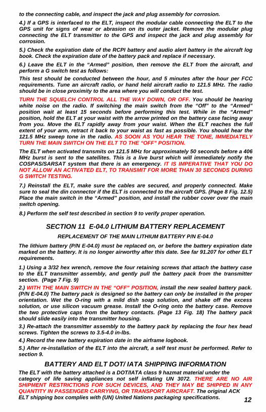
The lithium battery (P/N E-04.0) must be replaced on, or before the battery expiration date marked on the battery. It is no longer airworthy after this date. See far 91.207 for other ELT requirements.
1.) Using a 3/32 hex wrench, remove the four retaining screws that attach the battery case to the ELT transmitter assembly, and gently pull the battery pack from the transmitter section. (Page 7 Fig. 9)
2.) WITH THE MAIN SWITCH IN THE “OFF” POSITION, install the new sealed battery pack. (P/N E-04.0) The battery pack is designed so the battery can only be installed in the proper orientation. Wet the O-ring with a mild dish soap solution, and shake off the excess solution, or use silicon vacuum grease. Install the O-ring onto the battery case. Remove the two protective caps from the battery contacts. (Page 13 Fig. 18) The battery pack should slide easily into the transmitter housing.
3.) Re-attach the transmitter assembly to the battery pack by replacing the four hex head screws. Tighten the screws to 3.5-4.0 in-lbs.
4.) Record the new battery expiration date in the airframe logbook.
5.) After re-installation of the ELT into the aircraft, a self test must be performed. Refer to section 9.
13
The battery when shipped alone is a class 9 hazmat, under the category of lithium batteries UN 3090. If the total weight of the shipment exceeds 5 kg they are restricted from carriage in passenger carrying aircraft.
THE FOLLOWING IS AN EXCERPT FROM FAA AC 91-44A PARAGRAPH 8.a WHICH DEFINES WHEN ELT BATTERY REPLACEMENT MAY BE DONE UNDER 14 CFR PART
43.3(h) AS PREVENTIVE MAINTENANCE.
“…The replacement can be done by the pilot if the preventive maintenance limitations of part 43.3(h) of the FAR, are complied with. For example, a portable type ELT that is readily accessible and can be removed and reinstalled in the aircraft by a simple operation should be considered preventive maintenance. Fixed type ELT installations are often permanently mounted in a remote area of the aircraft near flight control cables, vital aircraft components, and critical attachments to the aircraft structure. Installations of this nature require an external antenna and often a remote on/off transmitter control switch that is usually located near the pilots flight position. This type of installation is complex and battery replacement should be accomplished by a certified mechanic or certified repair station…”
SECTION 13 WARRANTY PROCEDURE
Should it become necessary to return the ELT for warranty service. REMOVE THE ELT BATTERY BEFORE SHIPPING THE UNIT TO OUR FACILITY. The battery is DOT/IATA CLASS 9 HAZARDOUS MATERIAL, and DOT/IATA regulations must be followed whenever shipping the battery, or ELT and battery. See section 11 page 12 for additional shipping information.
All units must be returned to our facility freight prepaid. Our shipping Address is as follows:
ACK TECHNOLOGIES, INC. 440 W. JULIAN ST.
SAN JOSE, CA 95110 Provide an address that UPS will deliver to
SECTION 12 PROGRAMMING
THE ELT IS FACTORY PROGRAMMED TO THE STANDARD LOCATION SERIAL NUMBER FORMAT WITH U.S.A. COUNTRY CODE. (366)
The ELT may be programmed in the field to the following formats:
Serial number (you may only reprogram the country code in this format.)
Standard location 24-bit address
Standard location with operator designator & serial number
To reprogram the ELT you must use our programming dongle. (P/N E-04.prg Ver 2.1) the module interfaces to a PC operating Windows XP, Windows 7 Professional via a USB port.
The programming software and manual may be downloaded from our web site. WWW.ACKAVIONICS.COM.
DO NOT REMOVE SEALANT FROM BATTERY PACK SCREWS, OR DISASSEMBLE BATTERY PACK .TSO-C142a PROHIBITS OPENING OR REPLACING CELLS. IF THE BATTERY PACK IS OPENED BY ANYONE EXCEPT THE MANUFACTURER IT IS NO LONGER AIRWORTHY, AND THE WARRANTY IS VOID.

14
return shipment. (no PO boxes, or APO numbers) Please include a short description of the problem you have been experiencing, and a telephone number where you may be reached during business hours if possible. No RMA number is required.
Any unit that is returned for warranty, and found not to be defective will be charged a minimum handling and service charge, and returned C.O.D.
RECORD YOUR AIRCRAFT AND ELT INFORMATION FOR FUTURE REFERENCE AIRCRAFT __________________________________________________________
REGISTRATION NUMBER _________________________ COUNTRY ________________
INSTALLATION DATE _____________________________
ELT SERIAL NUMBER (FROM TSO LABEL) ___________________________
ELT HEX CODE (FROM RIGHT SIDE LABEL) ______________________________________
UPDATE REGISTRATION EVERY TWO YEARS
_____________ _____________ ____________ ____________ ____________ NEXT REG DUE NEXT REG DUE NEXT REG DUE NEXT REG DUE NEXT REG DUE
SECTION 14 CANADIAN MAINTENANCE REQUIREMENTS
In addition to our periodic maintenance requirements of section 10 In Canada you must comply with car part 5, chapter 571, appendix G maintenance requirements for continued airworthiness. We strongly recommend the “WS technologies inc” BT100av, or BT100avs tester be used to verify the performance characteristics of the ELT.
WEBSITE: WWW.WST.CA
THESE TESTS SHOULD ONLY BE PREFORMED IN A RF SCREEN ROOM.
When using conventional test equipment to perform this test:
Connect the RF output of the ELT to a spectrum analyzer with a 50 ohm impedance capable of measuring frequency, power, and perform the following tests. THE OUTPUT POWER DURING THE 406 MHz BURST IS + 37 dBm MAKE SURE THIS DOES NOT EXCEED THE MAXIMUM INPUT LEVEL OF THE ANALYZER. An attenuator may be necessary to reduce the input power to the analyzer. The test results must fall within the following minimum and maximum values:
406 FREQUENCY: 406.037000 MHz +/- 2 kHz POWER: 35 to 39 dBm
121.5 MHz FREQUENCY: 121.5 MHz +/- 6 kHz POWER: + 17 to 23 dBm
The current draw requirements of the regulations may be confirmed by removing the battery case, separating it from the transmitter head and using jumpers to connect the battery in series with the current meter.
CAUTION: THE POWER INPUT IS NOT PROTECTED FROM REVERSE POLARITY. IF REVERSE POLARITY IS APPLIED SEVERE DAMAGE WILL OCCUR, AND VOID THE WARRANTY.
STANDBY CURRENT IN THE ARMED MODE: ≤ 30 uA
THE G SWITCH ACTIVATION REQUIRED BY CAR PART 5, CHAPTER 571, APPENDIX G PAR (c) (3) (e) IS PREFORMED DURING THE SECTION 10 TESTING AND INSPECTION.
15
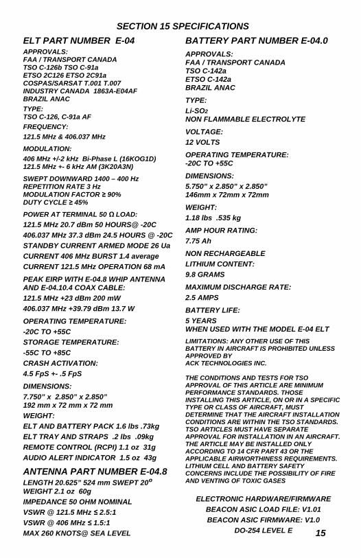
ELT PART NUMBER E-04
APPROVALS: FAA / TRANSPORT CANADA TSO C-126b TSO C-91a ETSO 2C126 ETSO 2C91a COSPAS/SARSAT T.001 T.007 INDUSTRY CANADA 1863A-E04AF BRAZIL ANAC
TYPE: TSO C-126, C-91a AF
FREQUENCY:
121.5 MHz & 406.037 MHz
MODULATION:
406 MHz +/-2 kHz Bi-Phase L (16KOG1D) 121.5 MHz +- 6 kHz AM (3K20A3N)
SWEPT DOWNWARD 1400 – 400 Hz REPETITION RATE 3 Hz MODULATION FACTOR ≥ 90% DUTY CYCLE ≥ 45%
POWER AT TERMINAL 50 Ω LOAD:
121.5 MHz 20.7 dBm 50 HOURS@ -20C
406.037 MHz 37.3 dBm 24.5 HOURS @ -20C
STANDBY CURRENT ARMED MODE 26 Ua
CURRENT 406 MHz BURST 1.4 average
CURRENT 121.5 MHz OPERATION 68 mA
PEAK EIRP WITH E-04.8 WHIP ANTENNA AND E-04.10.4 COAX CABLE:
121.5 MHz +23 dBm 200 mW
406.037 MHz +39.79 dBm 13.7 W
OPERATING TEMPERATURE:
-20C TO +55C
STORAGE TEMPERATURE:
-55C TO +85C
CRASH ACTIVATION:
4.5 FpS +- .5 FpS
DIMENSIONS:
7.750” x 2.850” x 2.850” 192 mm x 72 mm x 72 mm
WEIGHT:
ELT AND BATTERY PACK 1.6 lbs .73kg
ELT TRAY AND STRAPS .2 lbs .09kg
REMOTE CONTROL (RCPI) 1.1 oz 31g
AUDIO ALERT INDICATOR 1.5 oz 43g
ANTENNA PART NUMBER E-04.8 LENGTH 20.625” 524 mm SWEPT 20º WEIGHT 2.1 oz 60g
IMPEDANCE 50 OHM NOMINAL
VSWR @ 121.5 MHz ≤ 2.5:1
VSWR @ 406 MHz ≤ 1.5:1
MAX 260 KNOTS@ SEA LEVEL
BATTERY PART NUMBER E-04.0
APPROVALS: FAA / TRANSPORT CANADA TSO C-142a ETSO C-142a BRAZIL ANAC
TYPE:
Li-SO2
NON FLAMMABLE ELECTROLYTE
VOLTAGE:
12 VOLTS
OPERATING TEMPERATURE: -20C TO +55C
DIMENSIONS:
5.750” x 2.850” x 2.850” 146mm x 72mm x 72mm
WEIGHT:
1.18 lbs .535 kg
AMP HOUR RATING:
7.75 Ah
NON RECHARGEABLE
LITHIUM CONTENT:
9.8 GRAMS
MAXIMUM DISCHARGE RATE:
2.5 AMPS
BATTERY LIFE:
5 YEARS WHEN USED WITH THE MODEL E-04 ELT
LIMITATIONS: ANY OTHER USE OF THIS BATTERY IN AIRCRAFT IS PROHIBITED UNLESS APPROVED BY ACK TECHNOLOGIES INC. THE CONDITIONS AND TESTS FOR TSO APPROVAL OF THIS ARTICLE ARE MINIMUM PERFORMANCE STANDARDS. THOSE INSTALLING THIS ARTICLE, ON OR IN A SPECIFIC TYPE OR CLASS OF AIRCRAFT, MUST DETERMINE THAT THE AIRCRAFT INSTALLATION CONDITIONS ARE WITHIN THE TSO STANDARDS. TSO ARTICLES MUST HAVE SEPARATE APPROVAL FOR INSTALLATION IN AN AIRCRAFT. THE ARTICLE MAY BE INSTALLED ONLY ACCORDING TO 14 CFR PART 43 OR THE APPLICABLE AIRWORTHINESS REQUIREMENTS. LITHIUM CELL AND BATTERY SAFETY CONCERNS INCLUDE THE POSSIBILITY OF FIRE AND VENTING OF TOXIC GASES
SECTION 15 SPECIFICATIONS
ELECTRONIC HARDWARE/FIRMWARE
BEACON ASIC LOAD FILE: V1.01
BEACON ASIC FIRMWARE: V1.0
DO-254 LEVEL E
16
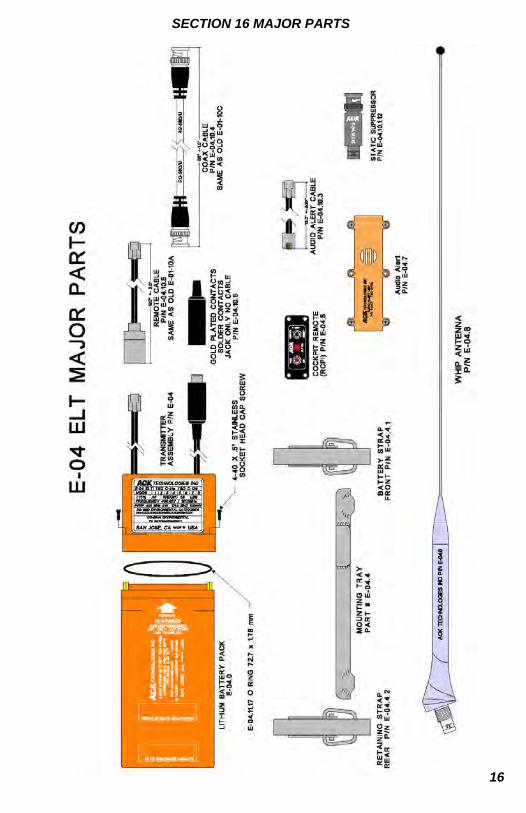
SECTION 16 MAJOR PARTS
17
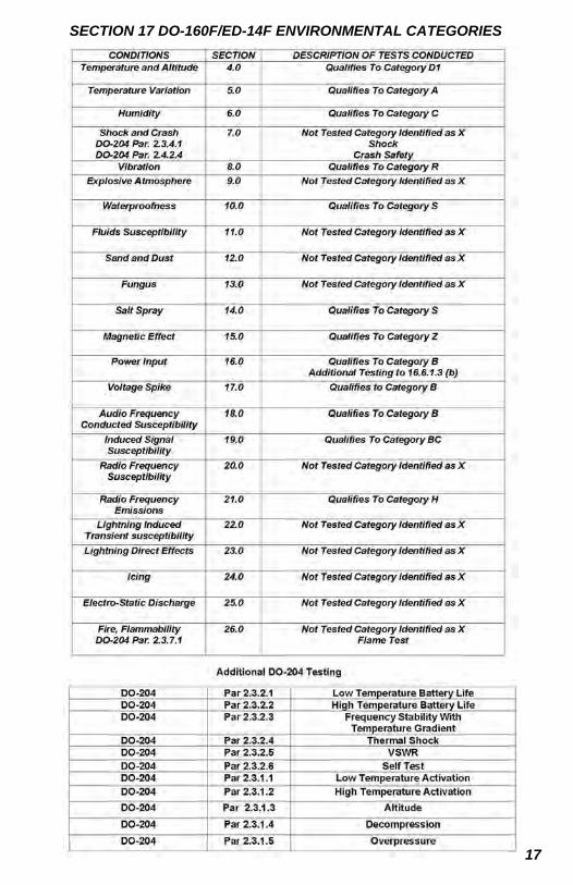
SECTION 17 DO-160F/ED-14F ENVIRONMENTAL CATEGORIES
18
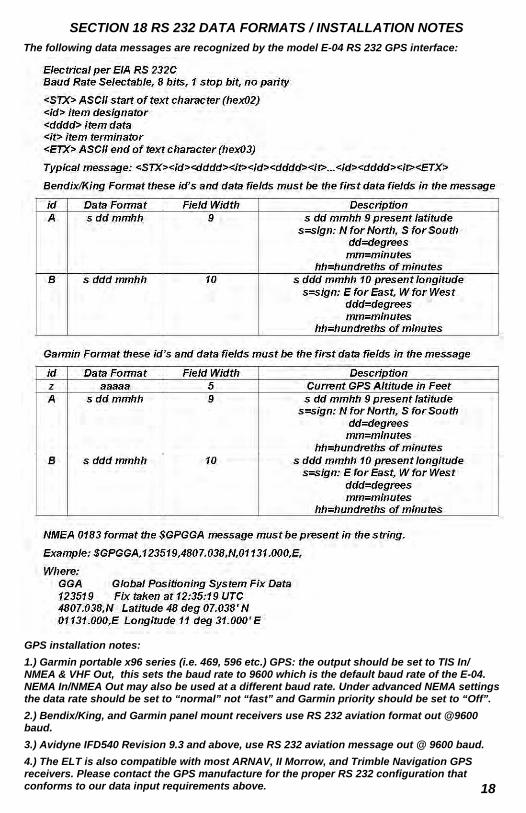
SECTION 18 RS 232 DATA FORMATS / INSTALLATION NOTES
The following data messages are recognized by the model E-04 RS 232 GPS interface:
GPS installation notes:
1.) Garmin portable x96 series (i.e. 469, 596 etc.) GPS: the output should be set to TIS In/NMEA & VHF Out, this sets the baud rate to 9600 which is the default baud rate of the E-04. NEMA In/NMEA Out may also be used at a different baud rate. Under advanced NEMA settings the data rate should be set to “normal” not “fast” and Garmin priority should be set to “Off”.
2.) Bendix/King, and Garmin panel mount receivers use RS 232 aviation format out @9600 baud.
3.) Avidyne IFD540 Revision 9.3 and above, use RS 232 aviation message out @ 9600 baud.
4.) The ELT is also compatible with most ARNAV, II Morrow, and Trimble Navigation GPS receivers. Please contact the GPS manufacture for the proper RS 232 configuration that conforms to our data input requirements above.
19
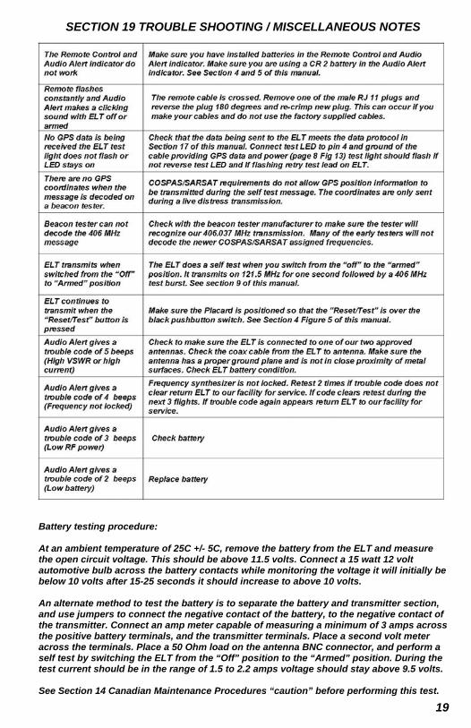
SECTION 19 TROUBLE SHOOTING / MISCELLANEOUS NOTES
Battery testing procedure: At an ambient temperature of 25C +/- 5C, remove the battery from the ELT and measure the open circuit voltage. This should be above 11.5 volts. Connect a 15 watt 12 volt automotive bulb across the battery contacts while monitoring the voltage it will initially be below 10 volts after 15-25 seconds it should increase to above 10 volts. An alternate method to test the battery is to separate the battery and transmitter section, and use jumpers to connect the negative contact of the battery, to the negative contact of the transmitter. Connect an amp meter capable of measuring a minimum of 3 amps across the positive battery terminals, and the transmitter terminals. Place a second volt meter across the terminals. Place a 50 Ohm load on the antenna BNC connector, and perform a self test by switching the ELT from the “Off” position to the “Armed” position. During the test current should be in the range of 1.5 to 2.2 amps voltage should stay above 9.5 volts. See Section 14 Canadian Maintenance Procedures “caution” before performing this test.
P
HO
NE
(40
8) 2
87-8
021
F
AX
(40
8) 9
71-6
879
HO
UR
S O
F O
PE
RA
TIO
N 9
:00a
m—
5:00
pm
PT
WE
BS
ITE
: W
WW
.AC
KA
VIO
NIC
S.C
OM
E
-MA
IL:
INF
O@
AC
KA
VIO
NIC
S.C
OM
L
IMIT
ED
WA
RR
AN
TY
T
HIS
MO
DE
L E
-04
EM
ER
GE
NC
Y L
OC
AT
OR
TR
AN
SM
ITT
ER
IS G
UA
RA
NT
EE
D B
Y A
CK
TE
CH
NO
LO
GIE
S, I
NC
. AG
AIN
ST
D
EF
EC
TS
IN M
AT
ER
IAL
S A
ND
WO
RK
MA
NS
HIP
FO
R A
PE
RIO
D O
F T
WO
YE
AR
S F
RO
M T
HE
INS
TA
LL
AT
ION
DA
TE
OR
T
WO
YE
AR
S T
HR
EE
MO
NT
HS
FR
OM
TH
E D
AT
E IT
WA
S M
AN
UF
AC
TU
RE
D W
HIC
HE
VE
R O
CC
UR
S F
IRS
T.
AC
TIV
AT
E
YO
UR
WA
RR
AN
TY
BY
RE
GIS
TE
RIN
G O
N L
INE
AT
OU
R W
EB
SIT
E W
WW
.AC
KA
VIO
NIC
S.C
OM
TH
IS W
AR
RA
NT
Y IS
L
IMIT
ED
EX
CL
US
IVE
LY
TO
RE
PA
IR O
R R
EP
LA
CE
ME
NT
OF
TH
E E
-04
EL
T A
ND
AS
SO
CIA
TE
D P
AR
TS
WH
ICH
WE
RE
M
AN
UF
AC
TU
RE
D B
Y A
CK
TE
CH
NO
LO
GIE
S, I
NC
. TH
E D
EF
EC
TIV
E P
AR
TS
MU
ST
BE
RE
TU
RN
ED
FR
EIG
HT
PR
EP
AID
T
O O
UR
MA
NU
FA
CT
UR
ING
FA
CIL
ITY
. TH
IS W
AR
RA
NT
Y D
OE
S N
OT
INC
LU
DE
RE
PA
IR O
R R
EP
LA
CE
ME
NT
OF
AN
Y
PA
RT
TH
AT
HA
S B
EE
N IM
PR
OP
ER
LY
US
ED
, IN
ST
AL
LE
D O
R P
HY
SIC
AL
LY
DA
MA
GE
D. T
HIS
WA
RR
AN
TY
DO
ES
NO
T
CO
VE
R A
NY
DA
MA
GE
CA
US
ED
BY
CH
EM
ICA
L E
XP
OS
UR
E T
O T
HE
EL
T. D
ISC
HA
RG
E O
F T
HE
LIT
HIU
M B
AT
TE
RY
IS
NO
T C
OV
ER
ED
BY
TH
IS O
R A
NY
OT
HE
R W
AR
RA
NT
Y. E
XC
EP
T A
S P
RO
VID
ED
HE
RE
IN A
CK
TE
CH
NO
LO
GIE
S, I
NC
. M
AK
ES
NO
EX
PR
ES
S W
AR
RA
NT
IES
, AN
D A
NY
IMP
LE
ME
NT
ED
WA
RR
AN
TY
OF
ME
RC
HA
NT
AB
ILIT
Y O
F F
ITN
ES
S F
OR
A
PA
RT
ICU
LA
R P
UR
PO
SE
IS L
IMIT
ED
IN IT
S D
UR
AT
ION
TO
TH
E D
UR
AT
ION
OF
TH
E W
RIT
TE
N L
IMIT
ED
WA
RR
AN
TIE
S
SE
T F
OR
TH
HE
RE
IN. A
CK
TE
CH
NO
LO
GIE
S, I
NC
. SH
AL
L N
OT
BE
LIA
BL
E F
OR
AN
Y D
IRE
CT
, IN
DIR
EC
T, S
PE
CIA
L O
R
CO
NS
EQ
UE
NT
IAL
DA
MA
GE
S A
RIS
ING
FR
OM
TH
E U
SE
OR
MIS
US
E O
F T
HIS
PR
OD
UC
T. E
XC
EP
T A
S P
RO
VID
ED
H
ER
EIN
NO
EM
PL
OY
EE
, A
GE
NT
, DE
AL
ER
, OR
OT
HE
R P
ER
SO
N IS
AU
TH
OR
IZE
D T
O G
IVE
AN
Y W
AR
RA
NT
IES
OF
AN
Y
NA
TU
RE
ON
BE
HA
LF
OF
AC
K T
EC
HN
OL
OG
IES
, IN
C.
YO
U M
AY
HA
VE
AD
DIT
ION
AL
LE
GA
L R
IGH
TS
WH
ICH
VA
RY
FR
OM
ST
AT
E T
O S
TA
TE


![Elt Artex Manual[1]](https://img.pdfslide.us/doc/110x75/5571f85c49795991698d4105/elt-artex-manual1.jpg)