Embed Size (px)
Citation preview

WARNING: Improper installation, adjustment, alteration, service or maintenance can cause injury or property damage. Refer to this manual. For assistance or additional information consult a qualified installer, service agency or the gas supplier.
—WHAT TO DO IF YOU SMELL GAS • DO NOT try to light any appliance. • DO NOT touch any electrical switch; do not use any phone in your building. • Leave the building immediately
• Immediately call your gas supplier from a phone remote from the building. Follow the gas suppliers instructions.
• If you cannot reach your gas supplier, call the Fire Department.
-- Installation and service must be performed by a qualified installer, service agency or the gas supplier.
FOR YOUR SAFETY: Do not store or use gasoline or other flammable vapors and liquids in the vicin-ity of this or any other appliance.
WARNING: If the information in these instructions are not followed exactly, a fire or explosion may result causing property damage, personal injury or loss of life.
201760185
OPERATINGINSTRUCTIONSANDOWNER’SMANUAL
READ INSTRUCTIONS CAREFULLY:Readandfollowallinstructions.Placeinstructionsinasafeplaceforfuturereference.Donotallowanyonewhohasnotreadtheseinstructionstoassemble,light,adjustoroperatetheheater.
Model#
www.mrheater.com •800-251-0001
MHU50MHU80MHU125
®
COMPACT UNIT HEATERFOR RESIDENTIAL/COMMERCIAL USE

CompactUnit/UtilityHeater OperatingInstructionsandOwner’sManual2
WARNING: FIRE OR EXPLOSION HAZARDFailuretofollowsafetywarningsexactlycouldresultinseriousinjury,deathorpropertydamage.Besuretoreadandunder-standtheinstallation,operation,andserviceinthismanual.Improperinstallation,adjustment,alteration,serviceormainte-nancecancauseseriousinjury,deathorpropertydamage.
WARNING: FIRE,BURN,INHALATION,ANDEXPLOSIONHAZARD.
KEEPSOLIDCOMBUSTIBLES,SUCHASBUILDINGMATERIALS,PAPERORCARDBOARD,ASAFEDISTANCEAWAYFROMTHEHEATERASRECOMMENDEDBYTHEINSTRUCTIONSNEVERUSETHEHEATERINSPACESWHICHDOORMAYCONTAINVOLATILEORAIRBORNECOMBUSTIBLES,ORPRODUCTSSUCHASGASOLINE,SOLVENTS,PAINTTHINNER,DUSTPARTICLESORUNKNOWNCHEMICALS.
CONTENTSUNITDIMENSIONS.................................................................. 3
SHIPPING................................................................................. 4
REQUIREMENTS....................................................................... 4
UNITHEATERINSTALLATION.................................................... 5
COMBUSTION&VENTILATIONAIR.......................................... 5
VENTING...............................................................................5-9
ELECTRICALCONNECTIONS..................................................... 9
GASCONNECTION.................................................................10
LEAKCHECK...........................................................................10
START-UPOPERATION.............................................................10
HEATINGSEQUENCEOFOPERATION...................................... 11
IGNITIONCONTROLLED......................................................... 11
ADJUSTMENTS........................................................................12
SERVICE..................................................................................12
WIRINGDIAGRAM..................................................................13
FUELCONVERSION.......................................................... 14-18
PARTSLIST..............................................................................19
WARRANTY............................................................................22
THE STATE OF CALIFORNIA REQUIRES THE FOLLOWING WARNINGS:
WARNING: Combustionby-productsproducedwhenusingthisproductcontaincarbonmonoxide,achemicalknowntotheStateofCaliforniatocausecancerandbirthdefects(orotherreproductiveharm).
WARNING: Thisproductcontainschemicals,includinglead,knowntotheStateofCaliforniatocausecancerandbirthdefectsorotherreproductiveharm.
LANGUAGESENGLISH..............................................................................1-22
SPANISH............................................................................23-45
FRENCH.............................................................................46-68
GENERAL INFORMATIONRETAINTHISMANUALFORFUTUREREFERENCE.FORQUESTIONS,PROBLEMS,MISSINGPARTSBEFORERETURNINGTORETAILERPLEASECALLWITHMODELNUMBERANDSERIALNUMBEROFHEATER:1-800-321-0001
MONDAY-FRIDAY8-5PMEASTERNTIMEORE-MAILUSINGTHEMR.HEATERWEBSITE:WWW.MRHEATER.COM
InordertoprovidethebestservicepossibleMr.Heaterisnowgivingyoumorewaystogetintouchwithus:
WEBSITE:Mr.Heater’sfulllineofproductarenowat: WWW.MRHEATER.COM
FACEBOOK:FindusonFacebook
TWITTER:Findusontwitter
YouTube:TherearenowinformationalvideosonYouTube.
WARNING:Yoursafetyisimportanttoyouandtoothers,sopleasereadtheseinstructionsbeforeyouoperatethisheater
125K unit 80K Unit 50K Unit
V/A/H/Phase 120v/3a/60hZ/1Φ 120v/2.3a/60hZ/1Φ 120v/2.3a/60hZ/1Φ
BTU Input 125,000BTU 80,000BTU 50,000BTU
BTU output 100,000BTU 64,000BTU 40,000BTU
Efficiency % 80% 80% 80%

CompactUnit/UtilityHeater OperatingInstructionsandOwner’sManual3
UNIT DIMENSIONS (N-NATURAL GAS, P-PROPANE)
SIDE VIEW
SERVICE ACCESS PANEL
HANGING BRACKETS (2)
ADJUSTABLE LOUVERS
TOP VIEW
MOUNTING SLOTS (Typical) 5/16 x 3 Inches (8 x 76 mm)
HANGING BRACKETS
AIR FLOW
HEAT EXCHANGER (ALUMINIZED STEEL)
START–UPANDPERFORMANCECHECKLIST JobName:__________________________________________
JobLocation:________________________________________
Installer:____________________________________________
UnitModelNo.:______________________________________
ElectricalConnectionsTight?_______________________________________________
SupplyVoltage___________________________________________________________
GasPipingConnectionsTight&Leak-Tested?__________________________________
MotorAmps_____________________________________________________________
FurnaceBtuInput________________________________________________________
LinePressure____________________________________________________________
ManifoldPressurew.c. ____________________________________________________
JobNo.:______________________________________
City:_________________________________________
City:_________________________________________
SerialNo.:_____________________________________
Date:_______________________________________
State/Province:_______________________________
State/Province:_______________________________
ServiceTechnician:____________________________
FlueConnectionsTight?__________________________________________________
FanTimerOperationChecked?_____________________________________________
THERMOSTAT
Calibrated?_____________________________________________________________
HeatAnticipatorProperlySet?
Level?_________________________________________________________________
Dimension 50 80 125
A 12(305) 17(432) 24.67”(626.8)
B 5.5”(140) 6.5”(165) 8.08”(205.25)
C 4.25”(108) 6.75”(171) 9.43”(239.61)
CompactUnit/UtilityHeater OperatingInstructionsandOwner’sManual4
SHIPPINGTheheateriscompletelyassembled.Installationinstructions,twomountingbrackets(shippedloose),andafluetransitionareincluded.Checktheunitforshippingdamage.Thereceivingpartyshouldcontactthelastcarrierimmediatelyifanyshippingdamageisfound.
REQUIREMENTS–CSAINTHEUSAInstallationofgasunitheatersmustconformwithlocalbuildingcodesor,intheabsenceoflocalcodes,withthecurrentNationalFuelGasCodeANSIZ223.1.
InstallationinaircrafthangersmustbeinaccordancewiththecurrentStandardforAircraftHangersANSI/NFPANo.409.
InstallationinparkingstructuresmustbeinaccordancewiththecurrentStandardforParkingStructuresANSI/NFPANo.88A.
InstallationinrepairgaragesmustbeinaccordancewiththecurrentStandardforRepairGaragesANSI/NFPANo.88B.
Theseunitsareapprovedforresidentialapplications.Forinstallationinaresidentialgaragetheseunitsmustbeinstalledsothatthebottomoftheheaterislocatednolessthan8feet(2.438m)abovefloor.Heatermustbelocatedorprotectedtoavoidphysicaldamagebyvehicles.RefertotheNationalFuelGasCode,ANSIZ223.1,currentedition.
AuthoritieshavingjurisdictionshouldbeconsultedbeforeNFPAinstallation.AirforcombustionandventilationmustconformtothemethodsoutlinedinANSIZ223.1,section5.3,AirforCombustionandVentilation,orapplicableprovisionsoflocalbuildingcodes.TheNationalFuelGasCodeisavailablefrom:
AmericanNationalStandardInstituteInc.11West42ndStreetNewYork,NY10036
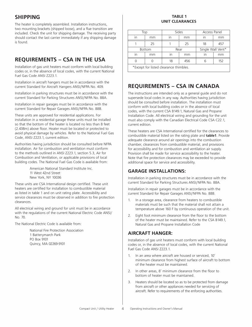
TheseunitsareCSAInternationaldesigncertified.Theseunitheatersarecertifiedforinstallationtocombustiblematerialaslistedintable1andonunitratingplate.Accessibilityandserviceclearancesmustbeobservedinadditiontofireprotectionclearances.
AllelectricalwiringandgroundforunitmustbeinaccordancewiththeregulationsofthecurrentNationalElectricCodeANSI/No.70.
TheNationalElectricCodeisavailablefrom:
NationalFireProtectionAssociation 1BatterymarchPark POBox9101 Quincy,MA02269-9101
REQUIREMENTS–CSAINCANADATheinstructionsareintendedonlyasageneralguideanddonotsupersedelocalcodesinanyway.Authoritieshavingjurisdictionshouldbeconsultedbeforeinstallation.Theinstallationmustconformwithlocalbuildingcodesorintheabsenceoflocalcodes,withthecurrentCSAB149.1,NaturalGasandPropaneInstallationCode.AllelectricalwiringandgroundingfortheunitmustalsocomplywiththeCanadianElectricalCodeCSAC22.1,currentedition.
TheseheatersareCSAInternationalcertifiedfortheclearancestocombustiblemateriallistedontheratingplateandtable1.Provideadequateclearancearoundairopeningsintothecombustionchamber,clearancesfromcombustiblematerial,andprovisionsforaccessibilityandforcombustionandventilationairsupply.Provisionshallbemadeforserviceaccessibilitytotheheater.Notethatfireprotectionclearancesmaybeexceededtoprovideadditionalspaceforserviceandaccessibility.
GARAGE INSTALLATIONS:InstallationinparkingstructuresmustbeinaccordancewiththecurrentStandardforParkingStructuresANSI/NFPANo.88A.
InstallationinrepairgaragesmustbeinaccordancewiththecurrentStandardforRepairGaragesANSI/NFPANo.88B.
1. Inastoragearea,clearancefromheaterstocombustiblematerialsmustbesuchthatthematerialshallnotattainatemperatureabove160°Fbycontinuousoperationoftheunit.
2. Eightfootminimumclearancefromthefloortothebottomoftheheatermustbemaintained.RefertotheCSAB149.1,NaturalGasandPropaneInstallationCode
AIRCRAFT HANGER:Installationofgasunitheatersmustconformwithlocalbuildingcodesor,intheabsenceoflocalcodes,withthecurrentNationalFuelGasCodeANSIZ223.1.
1. Inanareawhereaircraftarehousedorserviced,10’minimumclearancefromhighestsurfaceofaircrafttobottomoftheheatermustbemaintained.
2. Inotherareas,8’minimumclearancefromthefloortobottomofheatermustbemaintained.
3. Heatersshouldbelocatedsoastobeprotectedfromdamagefromaircraftorotherappliancesneededforservicingofaircraft.Refertorequirementsoftheenforcingauthorities.
TABLE 1 UNIT CLEARANCES
Top Sides AccessPanel
Bottom Rear SingleWallVent*
in mm in mm in mm
1 25 1 25 18 457
in mm in mm in mm
0 0 18 456 6 152
*Exceptforlistedclearancethimbles.

CompactUnit/UtilityHeater OperatingInstructionsandOwner’sManual5
Theseunitsarecertifiedforresidentialapplications.Forinstallationinaresidentialgarage,theseunitsmustbeinstalledsothatburnersandignitionsourcearelocatednolessthan18”(457mm)abovefloor.Heatermustbelocatedorprotectedtoavoidphysicaldamagebyvehicles.RefertoCSAB149.1,NaturalGasandPropaneInstallationCodecurrentedition.
INCANADA:Inaconfinedarea,theheatermustbeinstalledinaccordancewiththeCSAB149.1,NaturalGasandPropaneInstallationCode.Besuretocheckwithlocalcodesandordinancesforadditionalrequirements.
UNIT HEATER INSTALLATIONUnitisshippedreadyforinstallation.Unitmaybeinstalledasshowninfigure 1orinverted180odependingondesiredlocationasgovernedbyclearances,ventconnection,airdirection,gassupply,electricalsupplyandserviceaccessibility.
1. Ifinstallingunitinaninvertedposition:Removeandretainscrewssecuringdoorandrotatedoor180o.Securewithretainedscrews.Rotatelouversdirectingairflowasdesired.
2. Chooselocationformountingbrackets.
3. Removeandretainthreescrewsalongtopedge(bottomedgewheninverted)offrontofunit.
4. Alignscrewholesonmountingbracketwithholesalongtopedge(eitheruprightorinverted)ofunit.Secureonemountingbrackettofrontofunitwithretainedscrews.Secureothermountingbrackettobackofunitwithscrewsretainedonthebackofunit.
5. Tosupportunit,securemountingbrackettoceilingjoistortruss.Unitmayalsohangonrodsasshowninfigure 1.
COMBUSTION AND VENTILATION AIRAdequatefacilitiesforsupplyingairforcombustionandventilationmustbeprovidedinaccordancewiththelatesteditionofsection5.3,AirforCombustionandVentilation,oftheNationalFuelGasCode,ANSIZ223.1,intheU.S.A.,CSAB149.1NaturalGasandPropaneInstallationCode,orapplicableprovisionsoflocalbuildingcodes.
Allgasfiredappliancesrequireairtobeusedforthecombustionprocess.Inmanybuildingstoday,thereisanegativeindoorairpressurecausedbyexhaustfans,etc.Ifsufficientquantitiesofcombustionairarenotavailable,theheateroranotherappliancewilloperateinaninefficientmanner,resultinginincompletecombustionwhichcanresultintheproductionofexcessivecarbonmonoxide.
CAUTION: Insufficientcombustionaircancauseheadaches,nausea,dizziness,asphyxiationordeath.
Ifindoorairistobeusedforcombustion,itmustbefreeofthefollowingsubstancesorthelifeoftheheatexchangerwillbeadverselyaffected:chlorine,carbontetrachloride,cleaningsolvent,halogenrefrigerants,acids,cementsandglues,printinginks,fluorides,paintremovers,varnishes,oranyothercorrosives.
VENTING
A–GENERALRECOMMENDATIONSANDREQUIREMENTS
NOTE:Theventisapassageway,verticalornearlyso,usedtoconveyfluegasesfromanappliance,oritsventconnector,totheoutsideatmosphere.Theventconnectoristhepipeorductthatconnectsafuel-gasburningappliancetoaventorchimney.
Unitheatersmustbeventedincompliancewithalllocalcodesorrequirementsofthelocalutility,thecurrentstandardsofthe(American)NationalFuelGasCode,ANSIZ223.1or(Canada)CSAB149.1NaturalGasandPropaneInstallationCode,andthefollowinginstructions.
Ametalstamped/extrudedtransitionissuppliedwiththiscertifiedunit.Itmustnotbemodifiedoralteredandmustbeinstalledontheoutletoftheinduceddraftblowerassemblypriortotheinstallationoftheventorventconnector.Failuretocomplywiththisrequirementwillvoidthecertificationoftheunitbytheapprovalagencies.Alljointsshallbesecuredwithatleasttwocorrosionresistantscrews.Alljointsmustbecheckedforgastightnessafterinstallation.
B–VERTICALVENTSUSINGMETALVENTPIPE–COMMERCIALANDRESIDENTIALINSTALLATIONS
MHUcompactunitheatersarelistedasCategoryIappliancesforverticalventinstallations.
1. MHUunitheatersaretobeusedwithNFPA-orANSI-approvedchimneys,U.L.listedtypeB-1gasvents,singlewallmetalpipe,orlistedchimneyliningsystemforgasventingwhereapplicable,aswellasthemodificationsandlimitationslistedinfigure 2.SealsinglewallventmaterialaccordingtothesectionA - General Recommendations and Requirements.
2. Theventconnectorshallbe3”(76mm)diameteron50kunitsand4”(102mm)diameteron80&125kunits.Inallcases,afluetransitionpiece(supplied)isrequiredtofitovertheoutletoftheinduceddraftassemblyontheappliance.
3. Keeptheventconnectorrunsasshortaspossiblewithaminimumnumberofelbows.Refertothe(American)NationalFuelGasCodeANSIZ223.1or(Canada)CSAB149.1NaturalGasandPropaneInstallationCodeformaximumventandventconnectorlengths.Horizontalrunoftheventconnectorfromtheinduceddraftblowertothechimney/vent
INSTALL UNIT / UTILITY HEATER
SUPPORT RODSMOUNTING
BRACKETS (2)
FIGURE 1

CompactUnit/UtilityHeater OperatingInstructionsandOwner’sManual6
C–HORIZONTALVENTING–GENERALDuetochangestoZ83-82009CSA2.6-2009,theuseofsinglewallB-Ventisnolongerpermittedasanacceptablematerialwhenventinghorizontally,thischangecoversbothresidentialandcommercialinstallations.AllhorizontallyventedunitsmanufacturedafterJulyof2011mustbeventedasaCateroryIIIUnit/UtilityHeaterincompliancewithUL1738&ULS636.Commonventingisnotallowedwhenhorizontallyventingtheunitheater.
Theminimumhorizontalventlengthis5feet(914mm).
1. Ifpossible,donotterminatethehorizontalventthroughawallthatisexposedtoprevailingwind.Exposuretoexcessivewindscanaffectunitperformance.
2. Ventterminationmustbefreefromobstructionsandatleast12”(306mm)abovegradelevelandmaximumsnowheight.
3. Donotterminateventdirectlybelowroofeavesoraboveawalkway,oranyotherareawherecondensatedrippingmaybetroublesomeandmaycausesomestaining.Avoidwindowswheresteammaycausefoggingoricebuildup.
4. Whenhorizontallyvented,minimumclearanceforterminationfromanydoor,window,gravityairinlet,gasorelectricmeter,regulators,andreliefequipmentis4ft.(1.2m)forU.S.installations.RefertoNFPA54/ANSIZ223.1intheU.S.A.andCSAB149.1NaturalGasandPropaneInstallationCodeand.2inCanadaorwithauthoritieshavinglocaljurisdiction.InCanada,ventterminationmusthaveaminimum6ft.(1.8m)horizontalclearancefromgasandelectricmetersandreliefdevicesasspecifiedintheCanadianB149.1,NaturalGasInstallationCode.
cannotexceedthevaluesintable 2.
4. Whenthelengthofasinglewallvent,includingelbows,exceeds5feet(1.5m),theventshallbeinsulatedalongitsentirelengthwithaminimumof1/2”thickfoilfacedfiberglass1-1/2#densityinsulation.Ifasinglewallventisusedinanunheatedareaitshallbeinsulated.Failuretodosowillresultincondensationoffluegases.
5. Theunitmaybeventedverticallyasasingleapplianceorasacommonventwithothergas-firedappliances.Incommonventingsituations,ventconnectorsforotherappliancesmustmaintaina4”(100mm)verticalseparationbetweentheventconnectors.Refertocommonventingtablesinthe(American)NationalFuelGasCodeANSIZ223.1or(Canada)CSAB149.1NaturalGasandPropaneInstallationCodeforproperventsize.
6. Clearancetocombustiblematerialis6”(152mm)forsinglewallventmaterialexceptwherealistedclearancethimbleisused.ClearancetocombustiblematerialfortypeB-1ventorfactory-builtchimneyispermanufacturer’sinstructions.
7. Theventconnectorshallbesupportedwithoutanydipsorsags.Verticalventsshallbesupportedinaccordancewiththeirlistingandmanufacturers’instructions.Allhorizontalventconnectorrunsshallhaveaslopeuptotheverticalventofatleast1/4”perfoot(1mmper50mm).
8. AllverticaltypeB-1vents,singlewallvents,orlistedchimneyliningsystemmustbeterminatedwithalistedventcaporlistedroofassembly.
9. Theventmustextendatleast3’(1m)abovethehighestpointwhereitpassesthrougharoofofabuildingandatleast2’(0.6m)higherthananypartofabuildingwithinahorizontaldistanceof10’(3.05m)unlessotherwisespecifiedbythe(American)NationalFuelGasCode,ANSIZ223.1or(Canada)CAN/CGA-B149InstallationCode.Theventmustextendatleast5’(1.6m)abovethehighestconnectedequipmentfluecollar.
FIGURE 2
VENT TERMINATION ON SINGLE WALL VENT
SINGLE WALL TERMINATION
DOUBLE WALL (TYPE B-1) TERMINATION
ROOF FLASHING
ROOF PITCHEDFROM 0”TO 45”
2” CLEARANCETHIMBLESHALL NOT BE A
CONCEALED SPACE
ROOF FLASHING
ROOF PITCHEDFROM 0” TO 45”
12”MAXCLEARANCE TO BE AS
SPECIFIED ON TYPE“B”VENT PIPE
SEAL JOINT BETWEEN SINGLE WALL VENTAND “B”VENTAND THE ANNULAR SPACE OF THE “B”VENT
No.of Feet m Elbows
1 25 7.6
2 20 6.1
3 15 4.6
4 10 3.0
5 5 1.5
Maximumlengthofventconnectornottoexceed30ft.(9.1m).
TABLE 2MAXIMUM HORIZONTAL VENT
LENGTHS

CompactUnit/UtilityHeater OperatingInstructionsandOwner’sManual7
5. Ventterminationmustbeaminimumof4’(1.2m)belowor4’(1.2m)horizontallyfromanysoffitventorunder-eavevent.
6. Ventmustbeaminimumof6’fromaninsidecornerformedbytwoexteriorwalls.Ifpossible,leavea10’clearance.
7. Ventterminationmustbeaminimumof10’(3m)fromanyforcedairinlet(includesfreshairinletforotherappliances,suchasadryer).
8. Whenterminationisroutedthroughanexteriorcombustiblewalltheventmustbesupportedusingalistedclearancethimble.Sealtheconnectionbetweenthesinglewallanddoublewallpipesandtheannularspaceofthedoublewallpipeasshowninfigure2.Insideedgeofventterminationteemustbeatleast12inchesfromoutsidewallasshowninfigure 3.
9. Forhorizontalventing,theventpipeshallbesupportedwithhangersnomorethan3ft.(1m)aparttopreventmovementafterinstallation.
D–HORIZONTALVENTING–COMMERCIAL1. Horizontalcommercialinstallationsareforbuildingswhich
arenotattachedtolivingspaces.Theventmaybesinglewallventmaterialinstalledaccordingtothesections
Venting A - General Recommendations and Requirements andC - Horizontal Venting General andD - Horizontal Venting - Commercial. Refertofigure 3.
2. Theventpipediameterforhorizontalcommercialinstallationsshallbe4”(76mm)on50units.Becauseofthisatransitionpiecehasbeensuppliedandisalreadyattachedtoyourheater.Refertofigure4
3. Selectawallterminationpointthatwillmaintain1/4”riseperfootslopeofhorizontalrunofventpipe.
4. Forupwardslopedventacondensateteeanddrainmustbeinstalledwithinthefirst5’(1.5m)fromtheunitheatertoprotecttheappliance.Ifaflexiblecondensatedrainlineisused,thedrainlinemustincludealoopenteringthe
structure.Iftheunitisshutdownforanextendedperiodoftimeandwillbeexposedtosub-freezingtemperatures,thecondensatemayfreeze.
E–HORIZONTALVENTING–RESIDENTIAL1. Forhorizontalresidentialinstallationstheseunitsare
certifiedasCategoryIIIappliances.Venting A - General Recommendations and Requirements andC - Horizontal Venting General andE - Horizontal Venting - Residential.
Refertofigure 6.
2. Theventpipediameterforhorizontalresidentialinstallationsshallbe4”onallunits.Astandardventtransitionisrequiredatunitinadditiontothetransitionsuppliedwiththeunit.
3. Themaximumventlengthis25’(7.6m)plusone90-degreeelbow.Theminimumlengthis5’(1.5m).
4. Theventmustmaintaina1/4¼”riseperfootofslopeupwardstowardthetermination.
FIGURE 3
CONDENSATE DRAIN THROUGH TEE PIPE AND DRAIN LOOP UPWARD SLOPE ON HORIZONTAL VENT-COMMERCIAL INSTALLATION
CATEGORY III VENT ACCORDING TO THESE INSTALLATION INSTRUCTIONS. SLOPE: + 1/4 INCH FOR 1 FOOT RUN MINIMUM.
DRAIN LOOP WITH WATER TRAP (TO CONDENSATE DRAIN)
12 INCHES MIN. (30.5 CM)
LISTED THIMBLE THROUGH COMBUSTIBLE
WALL
EXHAUST VENT TERMINATION TEE
NOTE - MINIMUM HORIZONTAL LENGTH 3 FT. (914MM), UDING CAP FOR TERMINATION. REFER
FLUE TRANSITION (PROVIDED)
12” (30.5 CM) MINIMUM ABOVE ALL HIGHEST SNOWFALL
COMMON VENTING NOT ALLOWED WHEN HORIZONTALLY VENTING THE UNIT / UTILITY HEATER
FLUE TRANSITION (ATTACHED)
FIGURE 4
NOTE - MINIMUM HORIZONTAL LENGTH FT. (1.5M), NOT INCLUDING CAP FOR TERMINATION.
MAXIMUM HORIZONTAL LENGTH AND NUMBER OF ELBOWS REFER TO TABLE 2

CompactUnit/UtilityHeater OperatingInstructionsandOwner’sManual8
F–VENTINGUSINGAMASONRYCHIMNEYThefollowingadditionalrequirementsapplywhenalinedmasonrychimneyisbeingusedtoventthecompactunit/utilityheater.
1. MasonrychimneysusedtoventCategoryIunitsheatersmustbeeithertile-linedorlinedwithalistedmetalliningsystemordedicatedgasvent.Unlinedmasonrychimneysareprohibited.AcategoryIappliancemustneverbeconnectedtoachimneythatisservicingasolidfuelappliance.Ifafireplacechimneyflueisusedtoventthisappliance,thefireplaceopeningmustbepermanentlysealed.
2. Afanassistedunitheatermaybecommonlyventedintoanexistinglinedmasonrychimneyprovided:
• Thechimneyiscurrentlyservingatleastonedraft-hoodequippedappliance.
• Theventconnectorandchimneyaresizedinaccordancewithventingtablesinthe(American)NationalFuelGasCodeANSIZ223.1or(Canada)CSAB149.1NaturalGasandPropaneInstallationCode.
IMPORTANTSingleapplianceventingofafanassistedunitheaterintoatilelinedmasonrychimney(interiororoutsidewall)isprohibited.ThechimneymustfirstbelinedwitheithertypeB-1ventoraninsulatedsinglewallflexibleventliningsystem,sizedinaccordancewithventingtablesinthe(American)NationalFuelGasCodeANSIZ223.1or(Canada)CSAB149.1NaturalGasandPropaneInstallationCode.
3. AtypeB-1ventormasonrychimneylinershallterminateabovetheroofsurfacewithalistedcaporalistedroofassemblyinaccordancewiththetermsoftheirrespectivelistingsandtheventmanufacturer’sinstructions.
4. Donotinstallamanualdamper,barometricdraftregulator,orfluerestrictorbetweentheunitheaterandthechimney.
5. IftypeB-1double-wallventisusedinsideachimney,nootherappliancecanbeventedintothechimney.OuterwalloftypeB-1ventpipemustnotbeexposedtoflueproducts.
6. Insulationfortheflexibleventpipemustbeanencapsulatedfiberglasssleeverecommendedbytheflexibleventpipemanufacturer.
HORIZONTAL VENTING - RESIDENTIAL INSTALLATION UPWARD SLOPEINDUCED DRAFT BLOWER
12 INCHES MIN. (30.5CM)
VENT TERMINATION CAP
LISTED THIMBLE THROUGH COMBUSTION WALL
CATEGORY III VENT ACCORDING TO THESE INSTALLATION INSTRUCTIONS. SLOPED: + 1/4 INCH FOR 1 FOOT RUN MINIMUM.
NOTE - MINIMUM HORIZONTAL LENGTH 5FT. (1.5M), NOT INCLUDING CAP FOR TERMINATION.
MAXIMUM HORIZONTAL LENGTH AND NUMBER OF ELBOWS REFER TO TABLE 2
COMMON VENTING NOT ALLOWED WHEN HORIZONTALLY VENTING THE UNIT / UTILITY HEATER.
FLUE TRANSITION (PROVIDED)
FIGURE 6
7. ThespacebetweenlinerandchimneywallshouldNOTbeinsulatedwithpuffedmicaoranyotherloosegranularinsulatingmaterial.
8. IftypeB-1ventoraninsulatedflexibleventpipecannotbeusedasliners,thechimneymustberebuilttoaccommodateoneofthesemethodsorsomealternateapprovedmethodmustbefoundtoventtheappliance.Wheninspectionrevealsthatanexistingchimneyisnotsafefortheintendedpurpose,itshallberebuilttoconformtonationallyrecognizedstandards,linedorrelinedwithsuitablematerialsorreplacedwithagasventorchimneysuitableforventingunitheaters.Thechimneypassagewaymustbecheckedperiodicallytoensurethatitisclearandfreeofobstructions.
G–REMOVALOFUNITFROMCOMMONVENTIntheeventthatanexistingunitheaterisremovedfromaventingsystemcommonlyrunwithseparategasappliances,theventingsystemislikelytobetoolargetoproperlyventtheremainingattachedappliances.Thefollowingtestshouldbeconductedwhileeachapplianceisinoperationandtheotherappliancesarenotinoperation,yetremainconnectedtothecommonventingsystem.Iftheventingsystemhasbeeninstalledimproperly,thesystemmustbecorrected.
1. Sealanyunusedopeningsinthecommonventingsystem.
2. Visuallyinspecttheventingsystemforpropersizeandhorizontalpitch.Determinethereisnoblockageorrestriction,leakage,corrosion,orotherdeficiencieswhichcouldcauseanunsafecondition.
3. Ifpracticalcloseallbuildingdoorsandwindowsandalldoorsbetweenthespaceinwhichtheappliancesremainingconnectedtothecommonventingsystemarelocatedandotherspacesofthebuilding.Turnonclothesdryersandanyappliancesnotconnectedtothecommonventingsystem.Turnonanyexhaustfans,suchasrangehoodsandbathroomexhausts,sotheywilloperateatmaximumspeed.Donotoperateasummerexhaustfan.Closefireplacedampers.
4. Followthelightinginstructions.Placetheappliancebeinginspectedinoperation.Adjustthermostatsoappliancewilloperatecontinuously.

CompactUnit/UtilityHeater OperatingInstructionsandOwner’sManual9
5. Testforspillageatthedrafthoodreliefopeningafterfiveminutesofmainburneroperation.Usetheflameofamatchorcandle,orsmokefromacigarette,cigar,orpipe.
6. Afterithasbeendeterminedthateachapplianceremainingconnectedtothecommonventingsystemproperlyventswhentestedasoutlinedabove,returndoors,windows,exhaustfans,fireplacedampersandanyothergas-burningappliancetotheirpreviousconditionofuse.
7. Ifimproperventingisobservedduringanyoftheabovetests,thecommonventingsystemmustbecorrected.Thecommonventingsystemshouldbere-sizedtoapproachtheminimumsizeasdeterminedbyusingtheappropriatetables.
N
MANUAL MAIN SHUT-OFF VALVE
(FURNISHED BY INSTALLER)
GAS SUPPLY CONNECTION
GAS FLOW
DRIP LEG
GROUNDED JOINT UNION
LINE VOLTAGE FIELD WIRING
UNIT
BLACK
BLACK
WHITE
WHITE
EQUIPMENT GROUND
BLACK WIRE WITH WHITE TAPE OR WHITE WIRE WITHOUT TAPE
L1
FIGURE 7
GAS SUPPLY TO UNIT HEATER
ISOLATE GAS VALVE
MANUAL MAIN SHUT-OFF VALVE WILL NOT HOLD NORMAL TEST
PRESSURE
CAP
UNIT HEATER
FIGURE 8
FIGURE 9
ELECTRICAL CONNECTIONSNOTE:TheMHUseriesunit/utilityheatersuseadirectsparkignitionsystem.Thereisnopilotnecessaryasthesparklightsthemainburnerasthegasvalveisturnedon.Thedirectsparkignitioncontrolboardemitsradionoiseduringburnerignition.Thelevelofenergymaybeenoughtodisturbalogiccircuitinamicroprocessorcontrolledthermostat.Itisrecommendedthatanisolationrelaybeusedwhenconnectingtheunitheatertoamicroprocessorcontrolledthermostat.Selectcircuitprotectionandwiresizeaccordingtotheunitratingplate.Installaseparatedisconnectswitch(protectedbyeitherfuseorcircuitbreaker)neartheunitsothatpowercanbeturnedoffforservicing.Removeelectricaljunctionboxcoverandconnectwiringthroughknockoutonthejunctionboxlocatedonthesideoftheheater.Refertoheaterwiringdiagramforconnectioninformation.Use18gaugewireorlargerforlinepowerconnections.Makesuretoconnectlinepowertowireslocatedintheexternalelectricaljunctionboxbehindjunctionboxcover.DO NOT CONNECT LINE POWER TO THERMOSTAT TERMINAL STRIP ON OUTSIDE OF HEATER.
Electricallygroundtheunitinaccordancewithlocalcodesorintheabsenceoflocalcodes,inaccordancewiththecurrentNationalElectricalCode(ANSI/NFPANo.70)intheUSA,andinCanadawiththecurrentCanadianElectricalCode,Part1CSAC22.1
NOTE:Un-insulatedgroundwiremustbewrappedinelectricaltapetoavoiddamagetotheelectricalsystem.
Makelinevoltageconnectionsasshowninfigure7.Connectfieldwiringasshownonwiringdiagramonunit.Also,refertotypicaldiagraminthismanual.
Tousetheblowerforaircirculationonly,yourthermostatmusthavea“fanonly”orfanselectionsetting.Incaseyourthermostathasthisoption.anadditionalwireshouldberuntothe“G”terminalonthethermostatconnectionblock.Seewiringschematiconpage13.
CompactUnit/UtilityHeater OperatingInstructionsandOwner’sManual10
Whenconnectinggassupplylines,thelengthofthepipingrunfromthemetertotheheatermustbeconsideredindeterminingthepipesizetoavoidexcessivepressuredrop.Alinepressureof7”WC(178mmWC)fornaturalgasshouldbemaintainedwhensizingthepiping.
Alinepressureof13”WC(330mmWC)shouldbemaintainedforpropane(LP)gas.NOTE: CompoundsusedonthreadedjointsorgaspipingmustberesistanttotheactionsofLiquefiedpetroleumgasses.
WARNING: TO PREVENT HEATER DAMAGE. WHEN USING A PROPANE TANK TO SUPPLY HEATER, AMINIMUM11”W.C.LOWPRESSUREREGULATORTOAMAXIMUM14”W.C.LOWPRESSURE REGULATOR IS REQUIRED. THIS REGULATOR MUST BE INSTALLED BETWEEN THE TANK AND THE HEATER. Regulator not supplied with heater.
Forcorrectsizingofpiping,refertothe(American)NationalFuelGasCodeANSIZ223.1,or(Canada)CSAB149.1,NationalGasandPropaneInstallationCodeorconsulttheutilityhavingjurisdiction.
Adriplegshouldbeinstalledintheverticalpiperuntotheunit.Insomelocalities,codesmayrequirethatamanualmainshutoffvalveandunion(furnishedbyinstaller)beinstalledexternaltotheunit.Unionmustbeofthegroundjointtype.Adriplegshouldbereadilyaccessibletopermitcleaningandempting.Seefigure 8.
NOTE:Leaveaminof4’’clearancetotheelectricalconnectionsboxonthebackoftheheatertoallowforaccess.
A1/8”NPTpluggedtapshallbeinstalledimmediatelyupstreamofthegassupplyconnectiontotheheater.Thepurposeofthisistobeabletocheckforpropergaspressureenteringtheheater.
LEAK CHECKCAUTIONDONOTusematches,candles,flameorothersourcesofignitiontocheckforgasleaks.
Aftergaspipingiscompleted,carefullycheckallpipingconnections,(fieldandfactory),forgasleaks.Useasoapsolutionorotherpreferredmeans.
Duetothenaturalheatingcyclesandvibrationofthisunititisrecommended,aspartofitsannualmaintenance,tochecktheseconnectionsforpropertightnessandleak-checkwithasoapsolutionorotherpreferredmeanspriortoputtingintoservice.
IMPORTANTTheheateranditsindividualshutoffvalvemustbedisconnectedfromthegassupplypipingsystemduringanypressuretestingofthatsystemattestpressuresinexcessof1/2psig(3.45kPa).
Theappliancemustbeisolatedfromthegassupplypipingsystembyclosingitsindividualmanualgasshutoffvalveduringanypressuretestingofthegassupplysystemattestpressuresequaltoorlessthan1/2psig(3.45kPa).Seefigure 9.NOTEIncaseemergencyshutdownisrequired,shutdownmaingasvalveanddisconnectmainpowertounit.Thesedevicesshouldbeproperlylabeledbytheinstaller.
START–UPANDOPERATION
UNITSTART–UPFORYOURSAFETYREADBEFORELIGHTING
BEFORE LIGHTINGsmellallaroundtheapplianceareaforgas.Besuretosmellnexttothefloorbecausesomegasisheavierthanairandwillsettleonthefloor.
Useonlyyourhandtomovethegascontrolknobtotheonposition.Neverusetools.Donotuseexcessiveforcetoswitchvalvefromofftoonposition.Forceorattemptedrepairmayresultinafireorexplosion.
MHU50/80/125unitheatersareequippedwithanautomaticsparkignitionsystem.Thereisnopilot.Incaseofasafetyshutdown,movethermostatswitchtoOFF,thenreturnthethermostatswitchtoHEATposition.
Shouldoverheatingoccur,orthegassupplyfailtoshutoff,shutoffthemanualgasvalvetotheappliancebeforeshuttingofftheelectricalsupply.
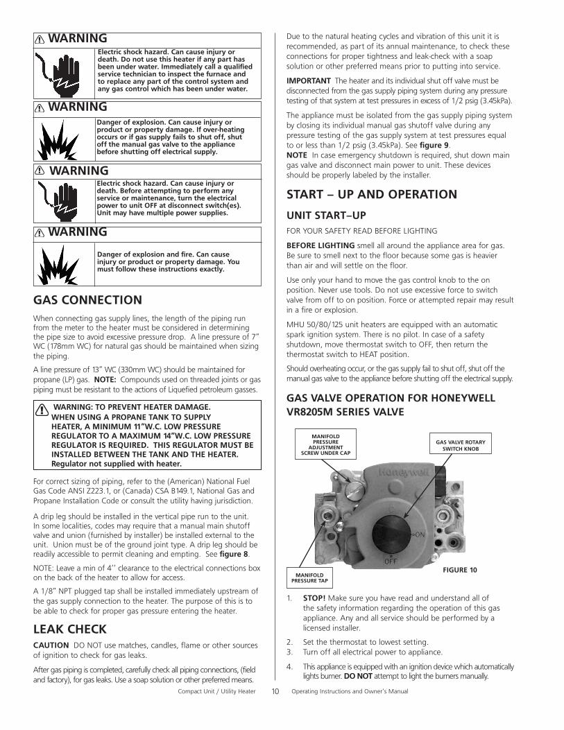
GAS VALVE OPERATION FOR HONEYWELL VR8205M SERIES VALVE
1. STOP!Makesureyouhavereadandunderstandallofthesafetyinformationregardingtheoperationofthisgasappliance.Anyandallserviceshouldbeperformedbyalicensedinstaller.
2. Setthethermostattolowestsetting.3. Turnoffallelectricalpowertoappliance.
4. Thisapplianceisequippedwithanignitiondevicewhichautomaticallylightsburner.DO NOTattempttolighttheburnersmanually.
WARNINGElectric shock hazard. Can cause injury or death. Do not use this heater if any part has been under water. Immediately call a qualified service technician to inspect the furnace and to replace any part of the control system and any gas control which has been under water.
Electric shock hazard. Can cause injury or death. Before attempting to perform any service or maintenance, turn the electrical power to unit OFF at disconnect switch(es). Unit may have multiple power supplies.
WARNING
Danger of explosion and fire. Can cause injury or product or property damage. You must follow these instructions exactly.
WARNINGDanger of explosion. Can cause injury or product or property damage. If over-heating occurs or if gas supply fails to shut off, shut off the manual gas valve to the appliance before shutting off electrical supply.
GAS CONNECTION
GAS VALVE ROTARY SWITCH KNOB
MANIFOLDPRESSURE
ADJUSTMENTSCREW UNDER CAP
MANIFOLDPRESSURE TAP
FIGURE 10
WARNING

CompactUnit/UtilityHeater OperatingInstructionsandOwner’sManual11
5. Thereisablackrotaryswitchknobthatcanbemovedbetweentheonandoffposition.Rotatetheswitchknobtotheoffposition.(SeeFigure10)
6. Waitfiveminutestoclearoutanygas.Ifyouthensmellgas,STOP!Immediatelycallyourgassupplierfromaneighbor’sphone.Followthegassupplier’sinstructions.Ifyoudonotsmellgasgotonextstep.
7. RotatetheblackswitchknobtoON.
8. Turnonelectricalpowertounit.
9. Setthethermostattodesiredsetting.
10. Thecombustionairblowerwillstart.Theburnerswilllightwithin30seconds.
11. Ifunitdoesnotlightfirsttime(gaslinenotfullypurged)itwillattemptuptotwomoreignitionsbeforelockingout.
12. Iflockoutoccurs,repeatsteps1through9.
13. Ifappliancestillwillnotoperate,followtheinstructions“TOTURNOFFGASTOUNIT”andcallyourservicetechnicianorgassupplier.
TO TURN OFF GAS TO UNIT1. Setthermostattolowestlevel.
2. Turnoffallelectricalpowertounitifserviceistobeperformed.
3. RotateblackknobtoOFFposition.
HEATING SEQUENCE OF OPERATION
1. Whenthethermostatcallsforheat,thecombustionairblowerstartsimmediately.
2. Combustionairpressureswitchprovesbloweroperationbeforeallowingpowertotheignitioncontroller.Thisswitchisfactorysetandnoadjustmentisnecessary.
3. Afterpre-purgeofapproximately30seconds,thesparkignitionisenergizedandthesolenoidvalveopensinthegasvalve.
4. Thesparkthenignitesthegas,theignitionsensorprovestheflameandthecombustionprocesscontinues.
5. Intheeventthattheflameisnotdetectedafterthefirst10-secondtrialforignition,thecontrollerwillrepeatsteps3and4anadditionaltwotimesbeforelockingoutthegasvalve.Refer to ignition control board table 3.Ignitioncontrolwillthenautomaticallyrepeatsteps3,4,and5after60minutes.
Tointerruptthe60-minutelockoutperiod,movethermostatfrom“HEAT”to“OFF”thenbackto“HEAT.”Heatingsequencethenrestartsatstep1.
6. Theburnersshalllightwithoutnoticeablecrossoverdelay.Thereshallbenoflameliftingfromtheburnerheads,flashbackorburningwithintheburner.Theflamesshallbepredominantlyblueincolorandshallbeapproximatelycenteredinthetubeswithnoapparentimpingementtakingplace.Ifyourburnercharacteristicsdonotmatchthosedescribedabove.Refertothetroubleshootingsections.
7. Theignitioncontrolwillenergizethefanapproximately45secondsafterignitionisestablished.
8. Afterthethermostatdemandissatisfiedthegasvalveisclosed;5secondsafterthedemandissatisfiedthecombustionairblowerisshutoff.
9. Thecontrolcentershallshutoffthesystemfanapproximately150secondsafterthegasvalveisde-energized.
IGNITION CONTROL LEDTheignitioncontrolboardcontainsagreenLEDwhichindicatesthefollowing:
TABLE 3 IGNITION CONTROL LED
LIMIT CONTROLThelimitcontrolswitchisfactorysetandnotfieldadjustable.
LOUVER VANE ADJUSTMENTS
Rotatelouvervanestodirectairflowupward,downward,straight,oranycombinationofthesedirections.Whenunitisinstalledinaninvertedposition,louversmaybepositionedinthesamemanner.
COMBUSTION AIR PRESSURE SWITCH
Thispressureswitchchecksforpropercombustionairbloweroperationbeforeallowinganignitiontrial.Theswitchisfactorysetandnofieldadjustmentisnecessary.Ifa3flashLEDoccursPleasemakesureyourventingisnotblockedup.Next,removetheendofthepressureswitchtubingfromtheEXHAUSTFANhosebarb.Theremightbeanobstructioninthehosebarbopeningclearouttheopeningwithathinobjectthatwillfitinsidethehosebarb.PushthatthroughthelengthofthehosebarbPLUSatleastanother1/2inch,intotheexhaustfanhousing.Thiswillclearoutanythingstoppingthevacuumfromengagingthepressureswitch.
FLAME ROLLOUT SWITCHTheflamerolloutswitch(es)arelocatedontheburnerboxtop,behindtheignitioncontrolboard.Thisnormallyclosedswitchopensonatemperaturerise.Checkforadequatecombustionairbeforemanuallyresettingswitch.
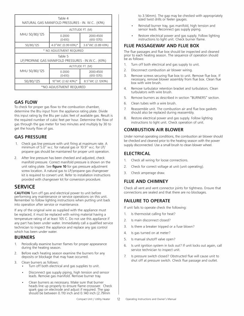
HIGH ALTITUDEUnitsmaybefiredatfullinputupto2000ft.(610m)abovesealevel.Above2000ft.(610m),manifoldpressuremustbeadjustedonsomeunits.Adjustpressureregulatortopressureshownintable 4fornaturalgasandtable 5forLP/propanegas.
LED UNIT OPERATION
SlowFlash* NormalOperation-Nocallforheat
FastFlash NormalOperation-Callforheat
CurrentsignalatFLAMEterminal0.6to1.0microamps
2Flashes Systemlockout-failedtodetectorsustainflame
CurrentsignalatFLAMEterminal<0.6microamps
3Flashes PressureswitchfailedclosedbeforeCABisenergized
orfailedopenafterCABisenergized
4Flashes Highlimitorrolloutswitchopen
5Flashes Flamesensedandgasvalvenotenergized
SteadyOff Lossofpower/Check3AMPFuseoncircuitboard
SteadyOn Ignitioncontrolfailure
*WhenthermostatisplacedincontinuousfanmodeLEDwillslowlyflash.
CompactUnit/UtilityHeater OperatingInstructionsandOwner’sManual12
GAS FLOWTocheckforpropergasflowtothecombustionchamber,determinetheBtuinputfromtheapplianceratingplate.DividethisinputratingbytheBtupercubicfeetofavailablegas.Resultistherequirednumberofcubicfeetperhour.Determinetheflowofgasthroughthegasmeterfortwominutesandmultiplyby30togetthehourlyflowofgas.
GAS PRESSURE1. Checkgaslinepressurewithunitfiringatmaximumrate.A
minimumof5.0”w.c.fornaturalgasor10.9”w.c.forLP/propanegasshouldbemaintainedforproperunitoperation.
2. Afterlinepressurehasbeencheckedandadjusted,checkmanifoldpressure.Correctmanifoldpressureisshownontheunitratingplate.Seefigure 10 forgaspressureadjustmentscrewlocation.AnaturalgastoLP/propanegaschangeoverkitisrequiredtoconvertunit.Refertoinstallationinstructionsprovidedwithchangeoverkitforconversionprocedure.
SERVICECAUTIONTurnoffgasandelectricalpowertounitbeforeperforminganymaintenanceorserviceoperationsonthisunit.Remembertofollowlightinginstructionswhenputtingunitbackintooperationafterserviceormaintenance.
Ifanyoftheoriginalwireassuppliedwiththeappliancemustbereplaced,itmustbereplacedwithwiringmaterialhavingatemperatureratingofatleast105°C.Donotusethisapplianceifanyparthasbeenunderwater.Immediatelycallaqualifiedservicetechniciantoinspecttheapplianceandreplaceanygascontrolwhichhasbeenunderwater.
BURNERS1. Periodicallyexamineburnerflamesforproperappearance
duringtheheatingseason.
2. Beforeeachheatingseasonexaminetheburnersforanydepositsorblockagethatmayhaveoccurred.
3. Cleanburnersasfollows:• Turnoffbothelectricalandgassuppliestounit.
• Disconnectgassupplypiping,hightensionandsensorleads.Removegasmanifold.Removeburnertray.
• Cleanburnersasnecessary.Makesurethatburnerheadslineupproperlytoensureflamecrossover.Checksparkgaponelectrodeandadjustifrequired.Thegapshouldbebetween0.110inchand0.140inch(2.79mm
to3.56mm).Thegapmaybecheckedwithappropriatelysizedtwistdrillsorfeelergauges.
• Reinstallburnertray,gasmanifold,hightensionandsensorleads.Reconnectgassupplypiping.
• Restoreelectricalpowerandgassupply.Followlightinginstructionstolightunit.Checkburnerflame.
FLUE PASSAGEWAY AND FLUE BOXThefluepassagesandflueboxshouldbeinspectedandcleanedpriortoeachheatingseason.Thesequenceofoperationshouldbeasfollows:
1. Turnoffbothelectricalandgassupplytounit.
2. Disconnectcombustionairblowerwiring.
3. Removescrewssecuringflueboxtounit.Removefluebox.Ifnecessary,removeblowerassemblyfromfluebox.Cleanflueboxwithwirebrush.
4. Removeturbulatorretentionbracketandturbulators.Cleanturbulatorswithwirebrush.
5. Removeburnersasdescribedinsection“BURNERS”section.
6. Cleantubeswithawirebrush.
7. Reassembleunit.Thecombustionairandflueboxgasketsshouldalsobereplacedduringreassembly.
8. Restoreelectricalpowerandgassupply.Followlightinginstructionstolightunit.Checkoperationofunit.
COMBUSTION AIR BLOWERUndernormaloperatingconditions,thecombustionairblowershouldbecheckedandcleanedpriortotheheatingseasonwiththepowersupplydisconnected.Useasmallbrushtocleanblowerwheel.
ELECTRICAL1. Checkallwiringforlooseconnections.
2. Checkforcorrectvoltageatunit(unitoperating).
3. Checkamperagedraw.
FLUE AND CHIMNEYCheckallventandventconnectorjointsfortightness.Ensurethatconnectionsaresealedandthattherearenoblockages.
FAILURE TO OPERATEIfunitfailstooperatecheckthefollowing:
1. Isthermostatcallingforheat?
2. Ismaindisconnectclosed?
3. Isthereabreakertrippedorafuseblown?
4. Isgasturnedonatmeter?
5. Ismanualshutoffvalveopen?
6. Isunitignitionsysteminlockout?Ifunitlocksoutagain,callservicetechniciantoinspectunit.
7. Ispressureswitchclosed?Obstructedfluewillcauseunittoshutoffatpressureswitch.Checkfluepassageandoutlet.
Table4NATURALGASMANIFOLDPRESSURES-IN.W.C..(KPA)
MHU50/80/125ALTITUDEFT.(M)
0-2000(0-610)
2000-4500(610-1370)
50/80/125 4.0”WC(0.99KPA)* 3.6”WC(0.89KPA)
*NOADJUSTMENTREQUIRED
Table5LP/PROPANEGASMANIFOLDPRESSURES-IN.W.C..(KPA)
MHU50/80/125ALTITUDEFT.(M)
0-2000(0-610)
2000-4500(610-1370)
50/80/125 10”WC(2.62KPA)* 8.5”WC(2.12KPA)
*NOADJUSTMENTREQUIRED

CompactUnit/UtilityHeater OperatingInstructionsandOwner’sManual13
LADDER DIAGRAM
ITISRECOMMENDEDTOUSE
OPTIONAL THERMOSTAT INSTALLATION
18AWGWIREWHENINSTALLINGTHETHERMOSTAT.CONNECT
TERMINALS‘R’AND‘W’THERMOSTATWIRINGTO
ASILLUSTRATEDONTHESCHEMATICDIAGRAM.
o É Ç
t Ü á íÉ
NOTE:THERMOSTATTERMINALCONNECTIONSAREMOUNTEDONTHEBACKPANELOFTHEHEATER.
EXTERNALTHERMOSTATTERMINALSTRIPWARNING:DO NOT CONNECTLINEPOWERTOTHETHERMOSTATTERMINALSTRIP.
Red
White

CompactUnit/UtilityHeater OperatingInstructionsandOwner’sManual14
HONEYWELLKIT#393691
Section 1 FUEL CONVERSION KITS
For L.P. - to - Natural Gas Conversions
FUEL CONVERSION INSTRUCTIONS
FuelConversionPartNumbers
Model# BTU/HR
Natural-To-LPF260163
MHU50 50,000
MHU80 80,000
MHU125 125,000
FuelConversionPartNumbers
Model# BTU/HR
Natural-To-LPF260164
MHU50 50,000
MHU80 80,000
MHU125 125,000
For Natural - to L.P. Gas Conversions
PartNumber Description 50 80 125
13575 Gasconversionlabel 1 1 1
60166-10 Ratingtag 1
60168-11 Ratingtag 1
11727 Spring-gasvalve(labelinc.) 1 1 1
60156 L.P.Orifice 3 5 8
13576 ControlConversionLabel 1 1 1
GasConversionLabels
OrificeP/N(SeeTableBelow)
HONEYWELLKIT#393691
GasConversionLabels
OrificeP/N(SeeTableBelow)
PartNumber Description 50 80 125
13575 Gasconversionlabel 1 1 1
60165-11 Ratingtag 1
60167-11 Ratingtag 1
11727 Spring-gasvalve(labelinc.) 1 1 1
60049 L.P.Orifice 3 5 8
13576 ControlConversionLabel 1 1 1

CompactUnit/UtilityHeater OperatingInstructionsandOwner’sManual15
Section 2 FUEL CONVERSION INSTRUCTIONSFigure1
WARNING: Explosion Hazard Turnoffthegassupplytotheheater beforeperforminganyserviceor maintenance.
Failuretofollowtheseinstructionswill resultindeath,injuryorpropertydamage.
WARNING: Electrical Shock Hazard Unplugtheelectricalcordfromtheoutlet beforeperforminganyservice maintenance.
Failuretofollowtheseinstructionswill resultindeath,injuryorpropertydamage.
Step 1
CAUTION THE UNIT MUST NOT BE CONNECTED TO EITHER THE GAS SUPPLY OR THE ELECTRICAL POWER SUPPLY, BEFORE PROCEEDING WITH CONVERSION.
Step 2Removeandretainthefourscrewsholdingthemanifoldontotheburnerbox(Figure1).Rotatethevalve/manifoldassembly,awayfromtheburners(Figure2).Thevalve/manifoldassemblyholdstheorifices(3-MHU50,5-MHU80,8-MHU125).Thiswillallowaccesstotheorificesonthemanifold,andalsotheadjustmentspringinthevalve/regulator.
Step 3Removeanddiscardtheadjustmentspringcapfromgasvalve/regulatorwithaflatbladescrewdriverbyturningthescrewcounter-clockwise.Removeanddiscardtheregulatoradjustmentscrewfoundunderthecap.Removeanddiscardthespringthatislocatedundertheadjustmentscrew.Takethespringkitfromtheconversionkit,andcomparethepartnumberofthekittothepartslistonpage3.Ifitdoesnotmatch,immediatelycontactMr.Heater,Inc.forthecorrectkit.Afterconfirmingthespringkitiscorrectfortheheatermodelyouareconverting,installthenewspringandadjustmentscrew.Turnspringadjustmentscrewclockwise(in)untilthescrewstops,thenturnitcounter-clockwise(back)1½turns.Placeconversionlabelsuppliedwiththespringkitonthevalveneartheadjustmentscrewcoveropening.
Step 4Removeanddiscardtheorifices(3-MHU50,5-MHU80,8-MHU125)fromthemanifoldwithusinga½“openendwrench.Turnthemcounter-clockwisetoremove.Taketheneworificesfromtheconversionkitandbeforeinstalling,confirmthatthenumberstampedonthesideoftheorificematchesthenumberforthekitbeinginstalled.Ifitdoesnot,immediatelycontactMr.Heater,Inc.forthecorrectkit.Iftheyarethecorrectorifices,installtheminthemanifoldusingcautionnottocrossthread.
The electrode and sensor are not adjustable. DO NOT change location or position as part of this conversion kit.
4Screws
RotateValve/ManifoldAssembly

CompactUnit/UtilityHeater OperatingInstructionsandOwner’sManual16
Figure2
N.G. L.P.
6
5
4
3
2
1
0
1
2
3
4
5
6
6
5
4
3
2
1
0
1
2
3
4
5
6
4" 10"
Step 5Rotatethevalve/manifoldassemblybackupintotheburnerbox,makingsurethatalltheorificesareindexedintotheburnersandarenotcaughtonthelocatingringonthebackofeachburner.Securethemanifoldtotheburnerboxwiththefourscrewsremovedinstep2.
Step 6Followingtheinstructionsintheunitheatersoperationsmanualmounttheheaterandconnectthegassupply(makingsuretoleakcheckallconnectionswithsoapywater).
Step 7Removevalvepressuretestplugandretainforlateruse.Connectawater-filledU-tubemanometertothetestport.SeeFigure2.Useamanometerbecausetestgaugesarenotreliableandmaygiveafalsereading.
Step 8Connectmainelectricalpowersupply,andturnmaingassupplyon.
Step 9Turnupthethermostattocallforheat,therebystartingtheignitionsequencefortheheater.
Step 10
Whentheburnerslight,setthemanifoldgaspressurebyturningtheadjustmentscrewtotheregulatorspringthatwasreplacedinstep6.Oncethehasbeenadjusted,replacetheadjustmentscrewcoverwithanewonefromtheconversionkit.
TheNaturalGasunitshouldbesetto4”WCandtheLPunitshouldbesetto10”WC.Themanometerillustration(SeeFigure2)showseachofthepressurereadings.
Step 11
Turndownthethermostatandallowtheheatertocompleteacooldowncycle.Thendisconnectmainelectricalpower,andturnthemaingassupplyofftoappliance.
Step 12
Disconnectthemanometerfromapplianceandreplacethetestplugonvalveremovedinstep6.

CompactUnit/UtilityHeater OperatingInstructionsandOwner’sManual17
Section 3 RATING TAG CONVERSION
Figure3
Figure4
INLET PRESSURES:
Natural Gas
MAX-14"WC(3.49kPa)
MIN-5"WC(1.25kPa)
Propane
MAX-14"WC(3.49kPa)
MIN-10"WC(2.74kPa)
Step 13
Connectmainelectricalpower,andturnmaingassupplybackon.Turnupthermostattocallforheat.Whenthemainburnerslightusingsoapywatercheckallconnectionsthoroughlyforgasleaks.Rememberingtoalsocheckthepressuretestplugreplacedinstep12.Allowtheheatertooperateforatleast5minutes,thenobservethemainburnerflame.Ahardblueflameextendingintothetubeisnormal.Slightyellowtippingisacceptable.Thereisnoairadjustmenttotheburner.
Step 14
Seefigure3.Removethedatatagfortheirrespectivegases.Removelabelandplaceovertheexistingportionofthetag.Thistagispreprintedwithallthecorrectinformationfortheconvertedheater.
Step 15
Removetheconvertedinformationtagfromthekitandfillintheinformation.Thenplacethistagbelowtheupdatedratingtagontheunit.
Step 16
Replaceanypanelsandoperateheaterfollowingallwarnings/cautionsandinstructionsintheoperator’smanualandlabels.
Table4NATURALGASMANIFOLDPRESSURES-IN.W.C..(KPA)
MHU50/80/125ALTITUDEFT.(M)
0-2000(0-610)
2000-4500(610-1370)
50/80/125 4.0”WC(0.99KPA)* 3.6”WC(0.89KPA)
*NOADJUSTMENTREQUIRED
TABLE5LP/PROPANEGASMANIFOLDPRESSURES-IN.W.C..(KPA)
MHU50/80/125ALTITUDEFT.(M)
0-2000(0-610)
2000-4500(610-1370)
50/80/125 10”WC(2.62KPA)* 8.5”WC(2.12KPA)
*NOADJUSTMENTREQUIRED
Figure5&Figure6
CompactUnit/UtilityHeater OperatingInstructionsandOwner’sManual18
P U
P R
P V
Q M
36
38
37
35
MrHeater•Compact/UtilityHeater•Model#MHU50/80
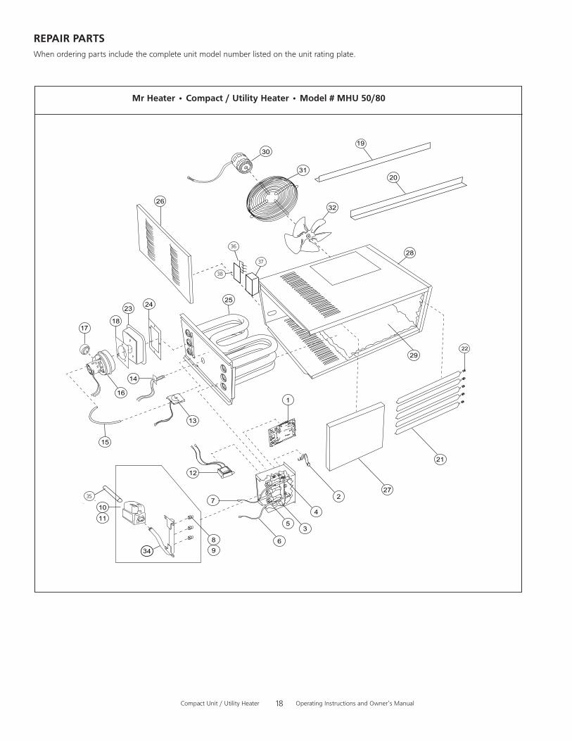
REPAIR PARTSWhenorderingpartsincludethecompleteunitmodelnumberlistedontheunitratingplate.
CompactUnit/UtilityHeater OperatingInstructionsandOwner’sManual19
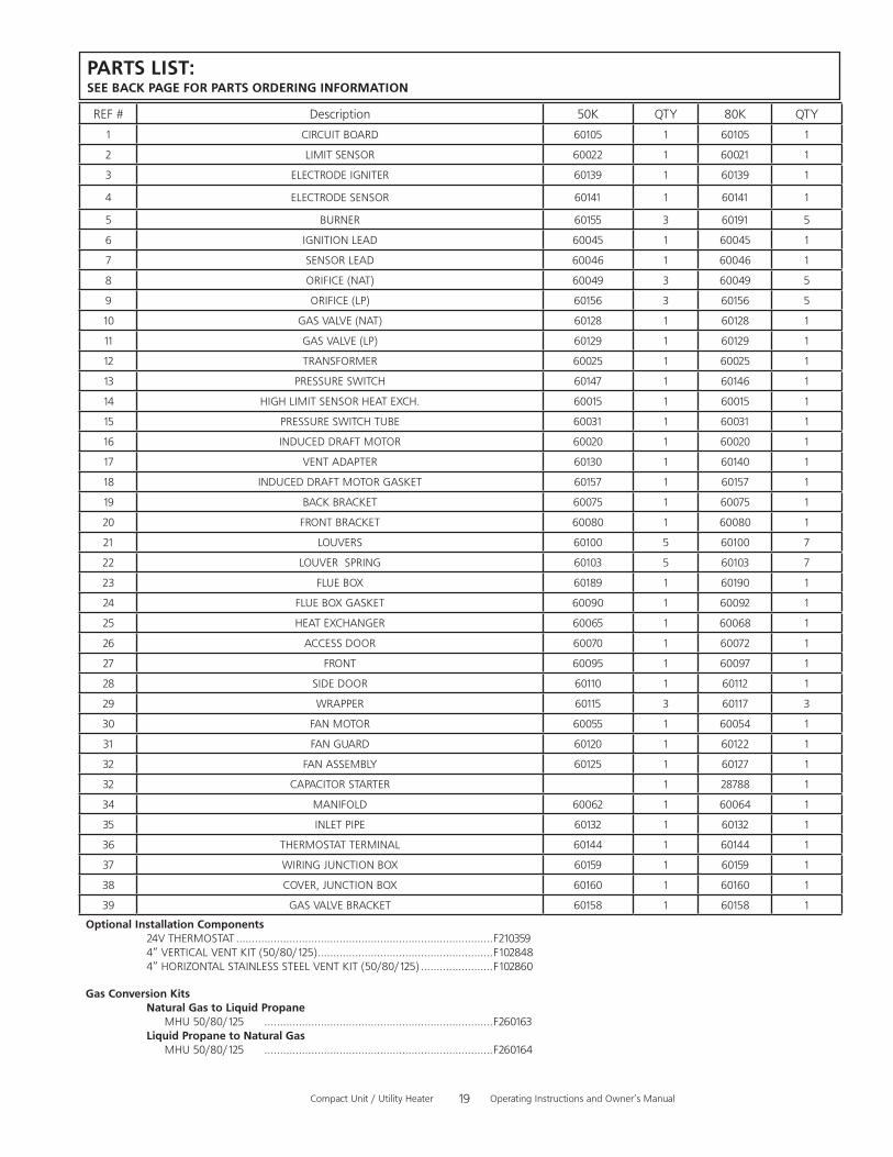
PARTS LIST:SEE BACK PAGE FOR PARTS ORDERING INFORMATION
Optional Installation Components 24VTHERMOSTAT..................................................................................F210359 4”VERTICALVENTKIT(50/80/125)........................................................F102848 4”HORIZONTALSTAINLESSSTEELVENTKIT(50/80/125).......................F102860
Gas Conversion Kits Natural Gas to Liquid Propane MHU50/80/125 .........................................................................F260163 Liquid Propane to Natural Gas MHU50/80/125 .........................................................................F260164
REF# Description 50K QTY 80K QTY
1 CIRCUITBOARD 60105 1 60105 1
2 LIMITSENSOR 60022 1 60021 1
3 ELECTRODEIGNITER 60139 1 60139 1
4 ELECTRODESENSOR 60141 1 60141 1
5 BURNER 60155 3 60191 5
6 IGNITIONLEAD 60045 1 60045 1
7 SENSORLEAD 60046 1 60046 1
8 ORIFICE(NAT) 60049 3 60049 5
9 ORIFICE(LP) 60156 3 60156 5
10 GASVALVE(NAT) 60128 1 60128 1
11 GASVALVE(LP) 60129 1 60129 1
12 TRANSFORMER 60025 1 60025 1
13 PRESSURESWITCH 60147 1 60146 1
14 HIGHLIMITSENSORHEATEXCH. 60015 1 60015 1
15 PRESSURESWITCHTUBE 60031 1 60031 1
16 INDUCEDDRAFTMOTOR 60020 1 60020 1
17 VENTADAPTER 60130 1 60140 1
18 INDUCEDDRAFTMOTORGASKET 60157 1 60157 1
19 BACKBRACKET 60075 1 60075 1
20 FRONTBRACKET 60080 1 60080 1
21 LOUVERS 60100 5 60100 7
22 LOUVERSPRING 60103 5 60103 7
23 FLUEBOX 60189 1 60190 1
24 FLUEBOXGASKET 60090 1 60092 1
25 HEATEXCHANGER 60065 1 60068 1
26 ACCESSDOOR 60070 1 60072 1
27 FRONT 60095 1 60097 1
28 SIDEDOOR 60110 1 60112 1
29 WRAPPER 60115 3 60117 3
30 FANMOTOR 60055 1 60054 1
31 FANGUARD 60120 1 60122 1
32 FANASSEMBLY 60125 1 60127 1
32 CAPACITORSTARTER 1 28788 1
34 MANIFOLD 60062 1 60064 1
35 INLETPIPE 60132 1 60132 1
36 THERMOSTATTERMINAL 60144 1 60144 1
37 WIRINGJUNCTIONBOX 60159 1 60159 1
38 COVER,JUNCTIONBOX 60160 1 60160 1
39 GASVALVEBRACKET 60158 1 60158 1

CompactUnit/UtilityHeater OperatingInstructionsandOwner’sManual20
MrHeater•Compact/UtilityHeater•Model#MHU125
42
4
7
25
21
8
2
315
5
6
45
32
9 10 11
12
14
13
16
23
18
39
24
22
40
19
25
28
27
26
30
35
31
1744
43
37
1
3433
41
29
20
36
38
44

CompactUnit/UtilityHeater OperatingInstructionsandOwner’sManual21
REF# Description 125 QTY
1 BRACKET 60200 2
2 MOUNTINGPANEL,MOTOR 60201 1
3 MOUNTINGPANEL,FRONTANDBACK 60202 2
4 MOUNTINGPANEL,BOTTOM 60203 1
5 MOUNTINGPANEL,SIDE 60204 1
6 MOUNTINGPANEL,TOP 60205 1
7 HEATEXCHANGER 60206 1
8 BRACKET,HEATEXCHANGE 60207 2
9 FANMOTOR 60208 1
10 FANGUARD 60209 1
11 FANASSEMBLY 60210 1
12 LOUVERS 60211 8
13 LOUVERSSPRING 60212 8
14 COVER,WIRINGJUNCTIONBOX 60160 1
15 WIRINGJUNCTIONBOX 60159 1
16 THERMOSTATTERMINAL 60144 1
17 VENTADAPTER 60213 1
18 INDUCEDDRAFTMOTOR 60214 1
19 INDUCEDDRAFTMOTORGASKET 60215 1
20 FLUEBOX 60216 1
21 FLUEBOXGASKET 60217 1
22 PRESSURESWITCHTUBE 60218 1
23 PRESSURESWITCH 60219 1
24 HILIMITSENSORHEATEXCH 60220 1
25 LIMITSENSOR 60221 2
26 CAP,FANMOTOR 28735 1
27 CAP,INDUCEDDRAFTMOTOR 60222 1
28 TRANSFORMER 60025 1
29 CIRCUITBOARD 60105 1
30 BRACKET,CAP 60223 1
31 SENSORLEAD 60046 1
32 ELECTRODESENSOR 60141 1
33 IGNITERLEAD 60224 1
34 ELECTRODEIGNITER 60139 1
35 BURNER 60155 8
36 BURNERBOX 60225 1
37 BRACKETBURNER 60226 1
38 ORIFICE(NAT) 60049 8
39 ORIFICE(LP) 60156 8
40 MANIFOLD 60227 1
41 GASVALVE(NAT) 60128 1
42 INLETPIPE 60132 1
43 GASVALVEBRACKET 60158 1
44 PANEL,BURNBOX 60228 1
*** INSULATIONPADDING 60220 1
PARTS LIST:SEE BACK PAGE FOR PARTS ORDERING INFORMATION

CompactUnit/UtilityHeater OperatingInstructionsandOwner’sManual22
WARNING:USEONLYMANUFACTURER’SREPLACEMENTPARTS.USEOFANYOTHERPARTSCOULDCAUSEINJURYORDEATH.REPLACEMENTPARTSAREONLYAVAILABLEDIRECTFROMTHEFACTORYANDMUSTBEINSTALLEDBYAQUALIFIEDSERVICEAGENCY.
PARTS ORDERING INFORMATION:PURCHASING: AccessoriesmaybepurchasedatanyMr.HeaterlocaldealerordirectfromthefactoryFOR INFORMATION REGARDING SERVICEPleasecallToll-Free800-251-0001•www.mrheater.comOurofficehoursare8:00AM–5:00PM,EST,MondaythroughFriday.Pleaseincludethemodelnumber,dateofpurchase,anddescriptionofprobleminallcommunication.
LIMITED WARRANTYThecompanywarrantsthisproducttobefreefromimperfectionsinmaterialorworkmanship,undernormalandproperuseinaccordancewithinstructionsofTheCompany,foraperiodofthreeyearsonparts(limited)and10yearsontheheatexchanger,fromthedateofdeliverytothebuyer.TheCompany,atitsoption,willrepairorreplaceproductsreturnedbythebuyertothefactory,transportationprepaidwithinsaidoneyearperiodandfoundbytheCompanytohaveimperfectionsinmaterialorworkmanship.
Ifapartisdamagedormissing,callourTechnicalSupportDepartmentat800-251-0001.
AddressanyWarrantyClaimstotheServiceDepartment,Mr.Heater,Inc.,4560W.160THST.,CLEVELAND,OHIO44135.Includeyourname,addressandtelephonenumberandincludedetailsconcerningtheclaim.Also,supplyuswiththepurchasedateandthenameandaddressofthedealerfromwhomyoupurchasedourproduct.
TheforegoingisthefullextentoftheresponsibilityoftheCompany.Therearenootherwarranties,expressorimplied.Specificallythereisnowarrantyoffitnessforaparticularpurposeandthereisnowarrantyofmerchantability.InnoeventshalltheCompanybeliablefordelaycausedbyimperfections,forconsequentialdamages,orforanychargesoftheexpenseofanynatureincurredwithoutitswrittenconsent.Thecostofrepairorreplacementshallbetheexclusiveremedyforanybreachofwarranty.Thereisnowarrantyagainstinfringementofthelikeandnoimpliedwarrantyarisingfromcourseofdealingorusageoftrade.Thiswarrantywillnotapplytoanyproductwhichhasbeenrepairedoralteredoutsideofthefactoryinanyrespectwhichinourjudgmentaffectsitsconditionoroperation.
Somestatesdonotallowtheexclusionorlimitationofincidentalorconsequentialdamages,sotheabovelimitationorexclusionmaynotapplytoyou.ThisWarrantygivesyouspecificlegalrights,andyoumayhaveotherrightswhichvaryfromstatetostate.
Mr.Heater,INC.,4560W.160THST.,CLEVELAND,OHIO44135•1-800-251-0001Mr.HeaterisaregisteredtrademarksofMr.Heater,Inc.©2016,Mr.Heater.Allrightsreserved
Mr.Heater,Inc.reservestherighttomakechangesatanytime,withoutnoticeorobligation,incolors,specifications,accessories,materialsandmodels.
OPERATING INSTRUCTIONS ANDOWNER’SMANUAL
READ INSTRUCTIONS CAREFULLY:Readandfollowallinstructions.Placeinstructionsinasafeplaceforfuturereference.Donotallowanyonewhohasnotreadtheseinstructionstoassemble,light,adjustoroperatetheheater.
MHU50MHU80MHU125
Model#
PRODUCTREGISTRATION:Thankyouforyourpurchase.Pleaselogintohttp://www.egiregistration.comtoregisteryourproduct.
®