Embed Size (px)
Citation preview
1 © 2013 The MathWorks, Inc.
Model-Based Design for effective HW/SW Co-Design
Alexander Schreiber – Senior Application Engineer
MathWorks, Germany
2
Model-Based Design of embedded Systems
Software Implementation and Verification
– Automatic C/C++ code generation
Hardware Implementation and Verification
– Floating- to fixed-point conversion
– Automatic HDL code generation
– Code optimization (speed, area, power)
– Verifiation on different levels of abstraction (HDL co-simulation, FIL)
HW/SW Integration on heterogeneous System-on-Chips (SoCs)
– Execution profiling (SIL, PIL)
– Generation of target-specific C code
– Generation of hardware IP interfacing internal system bus
– Workflow for HW/SW system integration
Questions & Answers
Agenda

3
Best Practice #1:
Enable collaboration by integrating workflows with
Model-Based Design
Best Practice #2:
Reduce development time with Automatic Code (C,
HDL) generation
Best Practice #3:
Reduce verification time with Test Bench Reuse
Things to remember ….

4 © 2013 The MathWorks, Inc.
Model-Based Design of embedded Systems
5
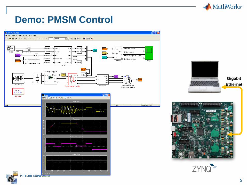
Demo: PMSM Control
Gigabit
Ethernet
6
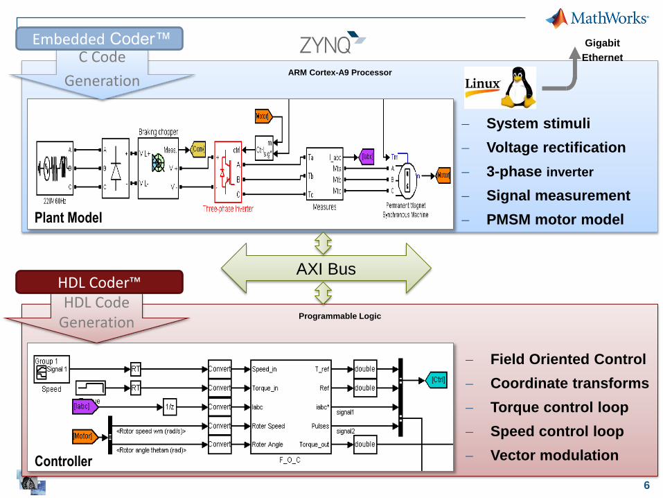
ARM Cortex-A9 Processor
AXI Bus
Programmable Logic
System stimuli
Voltage rectification
3-phase inverter
Signal measurement
PMSM motor model
Field Oriented Control
Coordinate transforms
Torque control loop
Speed control loop
Vector modulation
HDL Code Generation
C Code
Generation
Embedded Coder™
HDL Coder™
Plant Model
Controller
Gigabit
Ethernet

7
Mechanical
Components
MCAD/
MCAE
Electrical
Components
EDA
INTEGRATION AND TEST
SPECIFICATIONS
DESIGN
RESEARCH REQUIREMENTS
FPGA/
ASIC
HDL
IMPLEMENTATION
Requirement Documents
• Difficult to analyze
• Difficult to manage as they change
Paper Specifications
• Easy to misinterpret
• Difficult to integrate with design
Physical Prototypes
• Incomplete and expensive
• Prevents rapid iteration
• No system-level testing
Manual Coding
• Time consuming
• Introduces defects and variance
• Difficult to reuse
Traditional Testing
• Design and integration issues found late
• Difficult to feed insights back into design
process
• Traceability
Embeddable
Algorithms
Algorithm
Design
Traditional Flow
Embedded
Software
C/C++
8
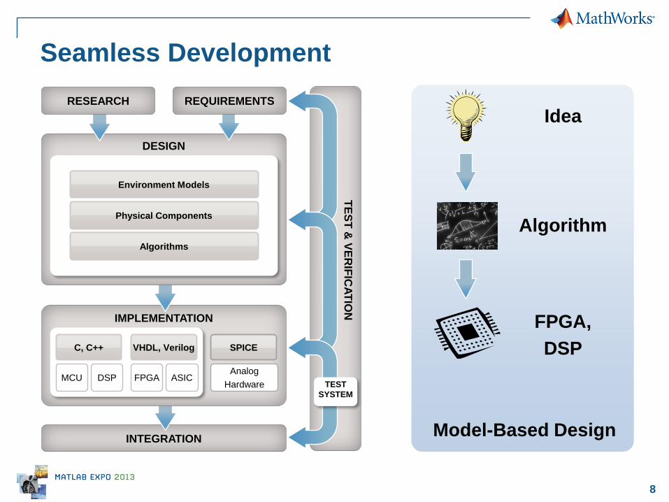
Model-Based Design INTEGRATION
IMPLEMENTATION
Analog
Hardware MCU DSP FPGA ASIC
SPICE VHDL, Verilog C, C++
DESIGN
Environment Models
Physical Components
Algorithms
REQUIREMENTS
TE
ST
& V
ER
IFIC
AT
ION
TEST
SYSTEM
Idea
Algorithm
FPGA,
DSP
RESEARCH
Seamless Development
9
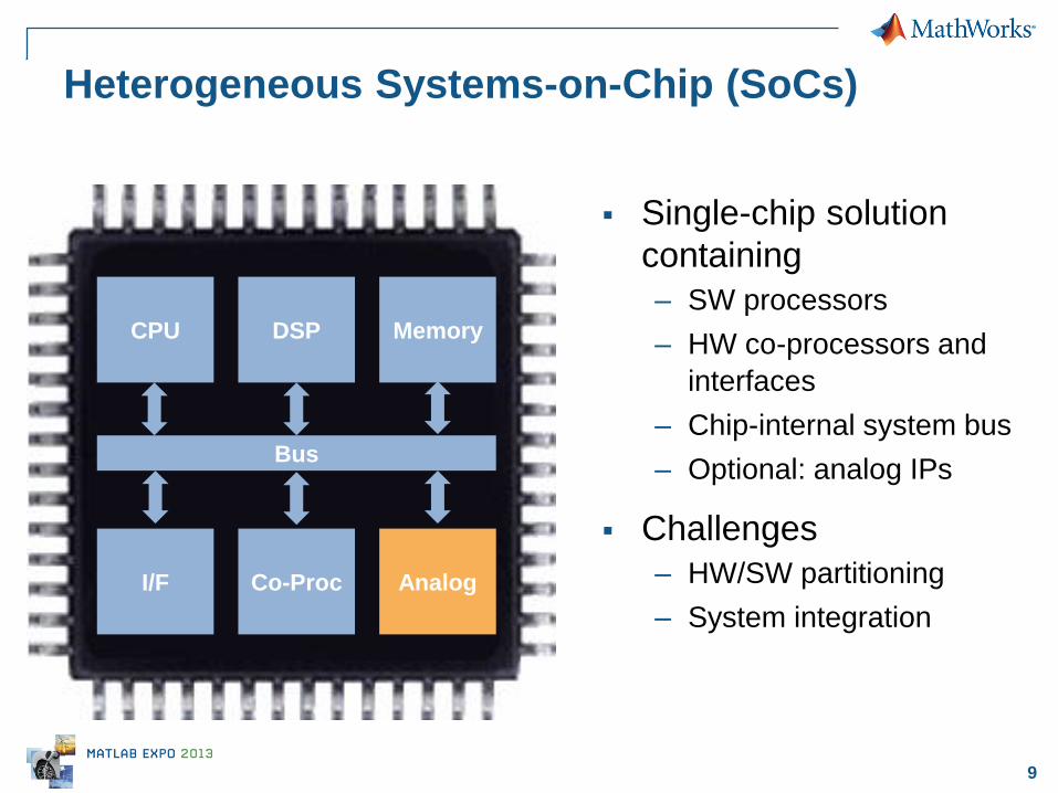
Heterogeneous Systems-on-Chip (SoCs)
CPU DSP
Co-Proc
Memory
I/F Analog
Bus
Single-chip solution
containing
– SW processors
– HW co-processors and
interfaces
– Chip-internal system bus
– Optional: analog IPs
Challenges
– HW/SW partitioning
– System integration
10 © 2013 The MathWorks, Inc.
Software Implementation and Verification
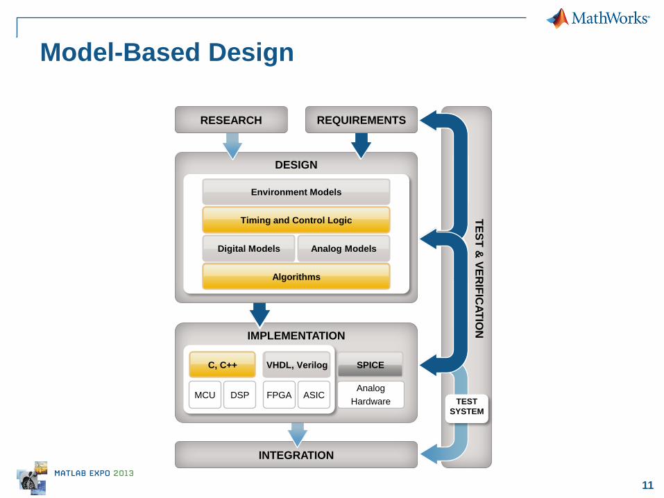
11
INTEGRATION
IMPLEMENTATION
Model-Based Design
DESIGN
T
ES
T &
VE
RIF
ICA
TIO
N
Timing and Control Logic
Digital Models Analog Models
SPICE VHDL, Verilog
TEST
SYSTEM
Analog
Hardware MCU DSP FPGA ASIC
C, C++
RESEARCH
VHDL, Verilog
Environment Models
Algorithms
C, C++
Algorithms
Timing and Control Logic
REQUIREMENTS
12
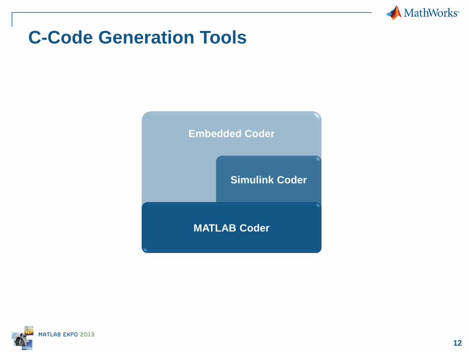
C-Code Generation Tools
Embedded Coder
Simulink Coder
MATLAB Coder
13
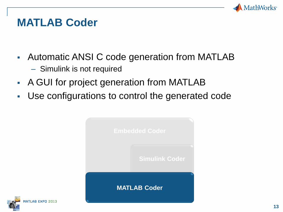
MATLAB Coder
Automatic ANSI C code generation from MATLAB
– Simulink is not required
A GUI for project generation from MATLAB
Use configurations to control the generated code
Embedded Coder
Simulink Coder
MATLAB Coder
14
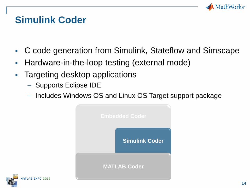
Simulink Coder
C code generation from Simulink, Stateflow and Simscape
Hardware-in-the-loop testing (external mode)
Targeting desktop applications
– Supports Eclipse IDE
– Includes Windows OS and Linux OS Target support package
Embedded Coder
Simulink Coder
MATLAB Coder
15
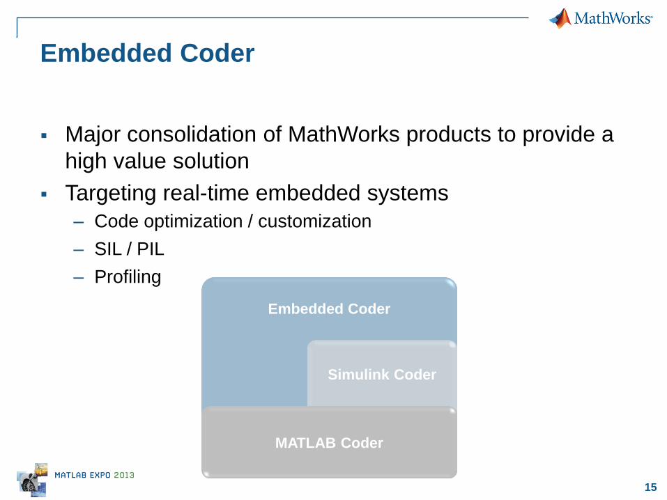
Embedded Coder
Major consolidation of MathWorks products to provide a
high value solution
Targeting real-time embedded systems
– Code optimization / customization
– SIL / PIL
– Profiling
Embedded Coder
Simulink Coder
MATLAB Coder

16 © 2013 The MathWorks, Inc.
Hardware Implementation and
Verification
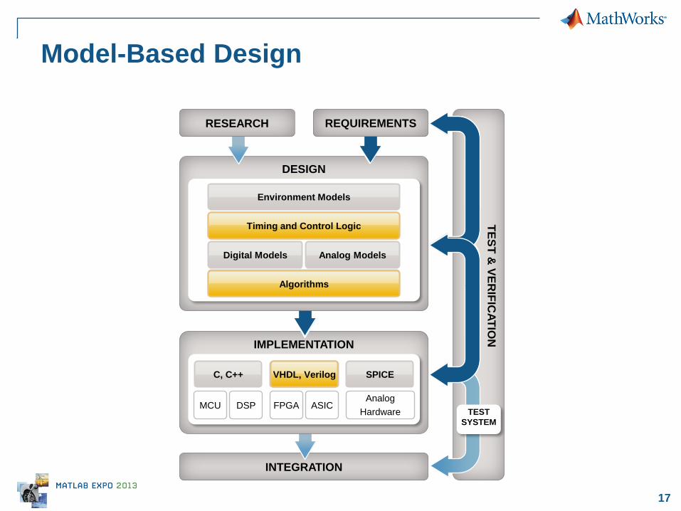
17
INTEGRATION
IMPLEMENTATION
Model-Based Design
DESIGN
T
ES
T &
VE
RIF
ICA
TIO
N
Timing and Control Logic
Digital Models Analog Models
SPICE VHDL, Verilog
TEST
SYSTEM
Analog
Hardware MCU DSP FPGA ASIC
C, C++
RESEARCH
VHDL, Verilog
Environment Models
Algorithms
VHDL, Verilog
Algorithms
Timing and Control Logic
REQUIREMENTS
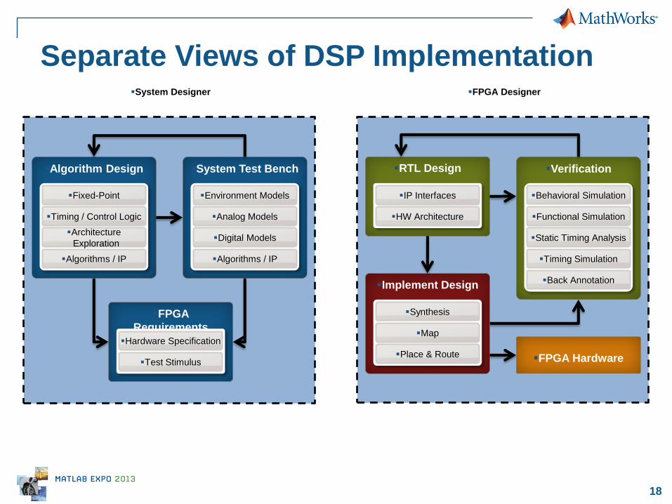
18
FPGA Designer System Designer
Algorithm Design
Fixed-Point
Timing / Control Logic
Architecture
Exploration
Algorithms / IP
System Test Bench
Environment Models
Algorithms / IP
Analog Models
Digital Models
RTL Design
IP Interfaces
HW Architecture
Verification
Functional Simulation
Static Timing Analysis
Timing Simulation
Behavioral Simulation
Back Annotation Implement Design
Map
Place & Route
Synthesis
FPGA Hardware
FPGA
Requirements
Hardware Specification
Test Stimulus
Separate Views of DSP Implementation
19
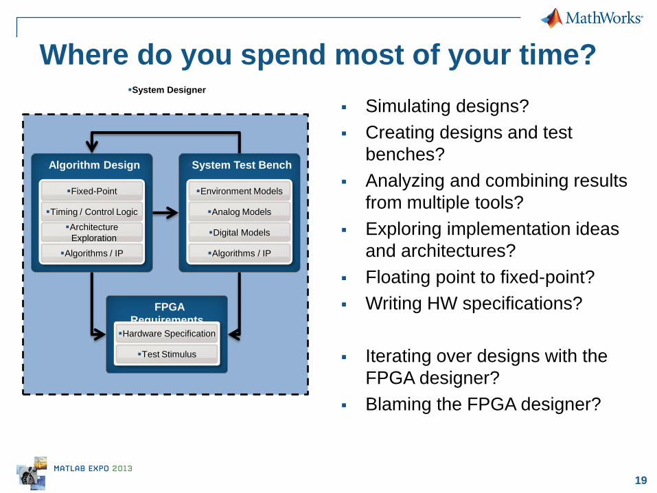
Where do you spend most of your time?
Simulating designs?
Creating designs and test
benches?
Analyzing and combining results
from multiple tools?
Exploring implementation ideas
and architectures?
Floating point to fixed-point?
Writing HW specifications?
Iterating over designs with the
FPGA designer?
Blaming the FPGA designer?
Algorithm Design
Fixed-Point
Timing / Control Logic
Architecture
Exploration
Algorithms / IP
System Test Bench
Environment Models
Algorithms / IP
Analog Models
Digital Models
FPGA
Requirements
Hardware Specification
Test Stimulus
System Designer
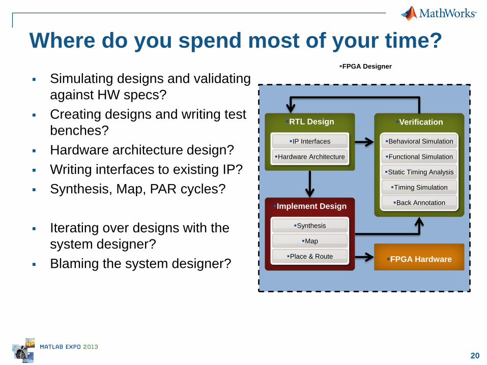
20
FPGA Designer
Where do you spend most of your time?
Simulating designs and validating
against HW specs?
Creating designs and writing test
benches?
Hardware architecture design?
Writing interfaces to existing IP?
Synthesis, Map, PAR cycles?
Iterating over designs with the
system designer?
Blaming the system designer?
RTL Design
IP Interfaces
Hardware Architecture
Verification
Functional Simulation
Static Timing Analysis
Timing Simulation
Behavioral Simulation
Back Annotation Implement Design
Map
Place & Route
Synthesis
FPGA Hardware
21
1. Increase simulation speed
2. Simplify design entry, system test harness
creation, and exploration
3. Automate RTL design & verification to have
shorter iteration cycles
4. Integrate the separate workflows to facilitate
collaboration, re-use, and prototyping
A Few Ways to Reduce Development Time
22
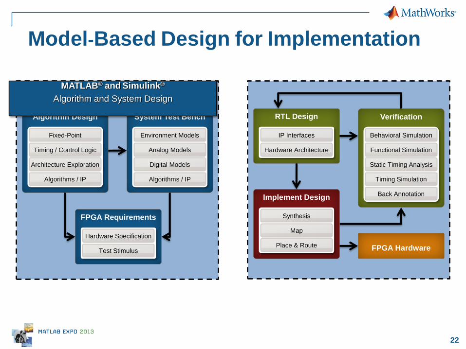
Model-Based Design for Implementation
Algorithm Design
Fixed-Point
Timing / Control Logic
Architecture Exploration
Algorithms / IP
System Test Bench
Environment Models
Algorithms / IP
Analog Models
Digital Models
RTL Design
IP Interfaces
Hardware Architecture
Verification
Functional Simulation
Static Timing Analysis
Timing Simulation
Behavioral Simulation
Back Annotation Implement Design
Map
Place & Route
Synthesis
FPGA Hardware
FPGA Requirements
Hardware Specification
Test Stimulus
MATLAB® and Simulink®
Algorithm and System Design
23
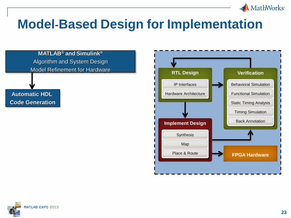
MATLAB® and Simulink®
Algorithm and System Design
Model Refinement for Hardware
Model-Based Design for Implementation
RTL Design
IP Interfaces
Hardware Architecture
Verification
Functional Simulation
Static Timing Analysis
Timing Simulation
Behavioral Simulation
Back Annotation Implement Design
Map
Place & Route
Synthesis
FPGA Hardware
Automatic HDL
Code Generation

24
MATLAB® and Simulink®
Algorithm and System Design
Model Refinement for Hardware
Model-Based Design for Implementation
Verification
Functional Simulation
Static Timing Analysis
Timing Simulation
Behavioral Simulation
Back Annotation Implement Design
Map
Place & Route
Synthesis
FPGA Hardware
HDL Co-Simulation
Automatic HDL
Code Generation
Behavioral Simulation
25
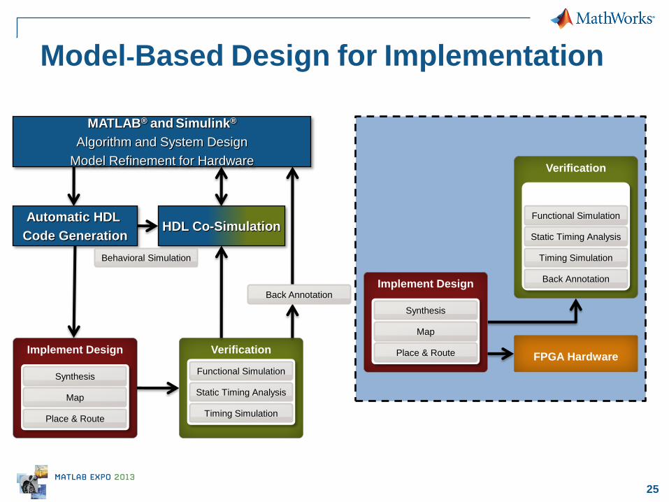
Model-Based Design for Implementation
Verification
Static Timing Analysis
Timing Simulation
Back Annotation Implement Design
Map
Place & Route
Synthesis
FPGA Hardware
Implement Design
Map
Place & Route
Synthesis
Functional Simulation
Verification
Static Timing Analysis
Timing Simulation
Functional Simulation
Back Annotation
HDL Co-Simulation
Automatic HDL
Code Generation
Behavioral Simulation
MATLAB® and Simulink®
Algorithm and System Design
Model Refinement for Hardware
26
FPGA Hardware
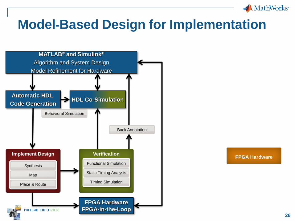
Model-Based Design for Implementation
Implement Design
Map
Place & Route
Synthesis
Verification
Static Timing Analysis
Timing Simulation
Functional Simulation
Back Annotation
HDL Co-Simulation
Automatic HDL
Code Generation
Behavioral Simulation
MATLAB® and Simulink®
Algorithm and System Design
Model Refinement for Hardware
FPGA Hardware
FPGA-in-the-Loop

27
Automatic HDL Code Generation

28
From Algorithm to Synthesizable RTL
Implement Design
Map
Place & Route
Synthesis
Verification
Static Timing Analysis
Timing Simulation
Functional Simulation
Back Annotation
HDL Co-Simulation
Automatic HDL
Code Generation
Behavioral Simulation
MATLAB® and Simulink®
Algorithm and System Design
Model Refinement for Hardware
FPGA Hardware
FPGA-in-the-Loop

29
Fixed-Point Analysis Corner Detection
Convert floating point to optimized fixed-point models
– Automatic tracking of signal range (also intermediate quantities)
– Word / Fraction lengths recommendation
Bit-true models in the same environment
Automatically
identify and solve
fixed-point issues

30
Algorithm to HDL Workflows
Simulink to HDL (with MATLAB and Stateflow)
MATLAB to HDL
Hybrid workflow 2 1
3
VHDL &
Verilog VHDL & Verilog
31
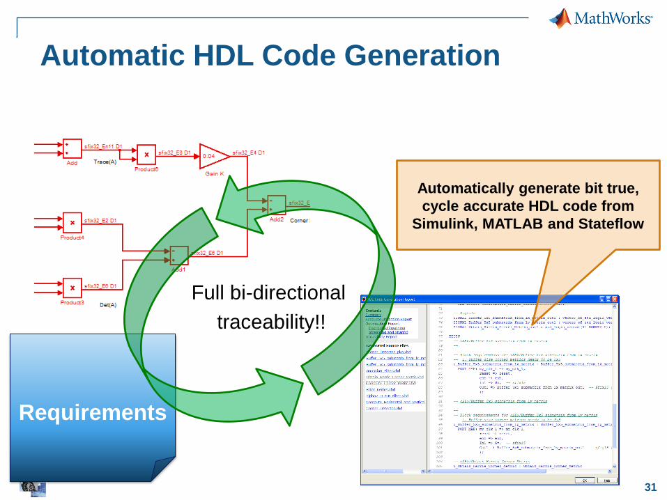
Requirements
Automatic HDL Code Generation
Full bi-directional
traceability!!
Automatically generate bit true,
cycle accurate HDL code from
Simulink, MATLAB and Stateflow
32
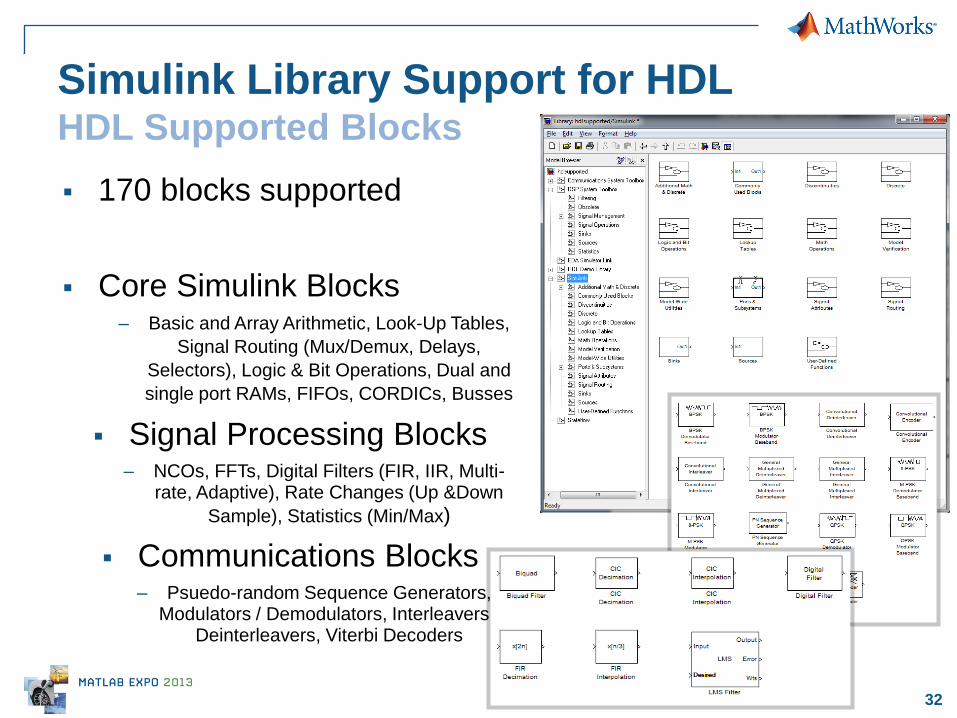
Simulink Library Support for HDL HDL Supported Blocks 170 blocks supported
Core Simulink Blocks – Basic and Array Arithmetic, Look-Up Tables,
Signal Routing (Mux/Demux, Delays,
Selectors), Logic & Bit Operations, Dual and
single port RAMs, FIFOs, CORDICs, Busses
Signal Processing Blocks – NCOs, FFTs, Digital Filters (FIR, IIR, Multi-
rate, Adaptive), Rate Changes (Up &Down
Sample), Statistics (Min/Max)
Communications Blocks – Psuedo-random Sequence Generators,
Modulators / Demodulators, Interleavers / Deinterleavers, Viterbi Decoders

33
MATLAB – Relevant subset of the MATLAB
language for modeling and generating HDL implementations
– eml_hdl_design_patterns:
Useful MATLAB Function Block
Design Patterns for HDL
Stateflow
– Graphical tool for modeling Mealy
and Moore Finite State Machines
MATLAB & Stateflow for HDL HDL Supported Blocks
34
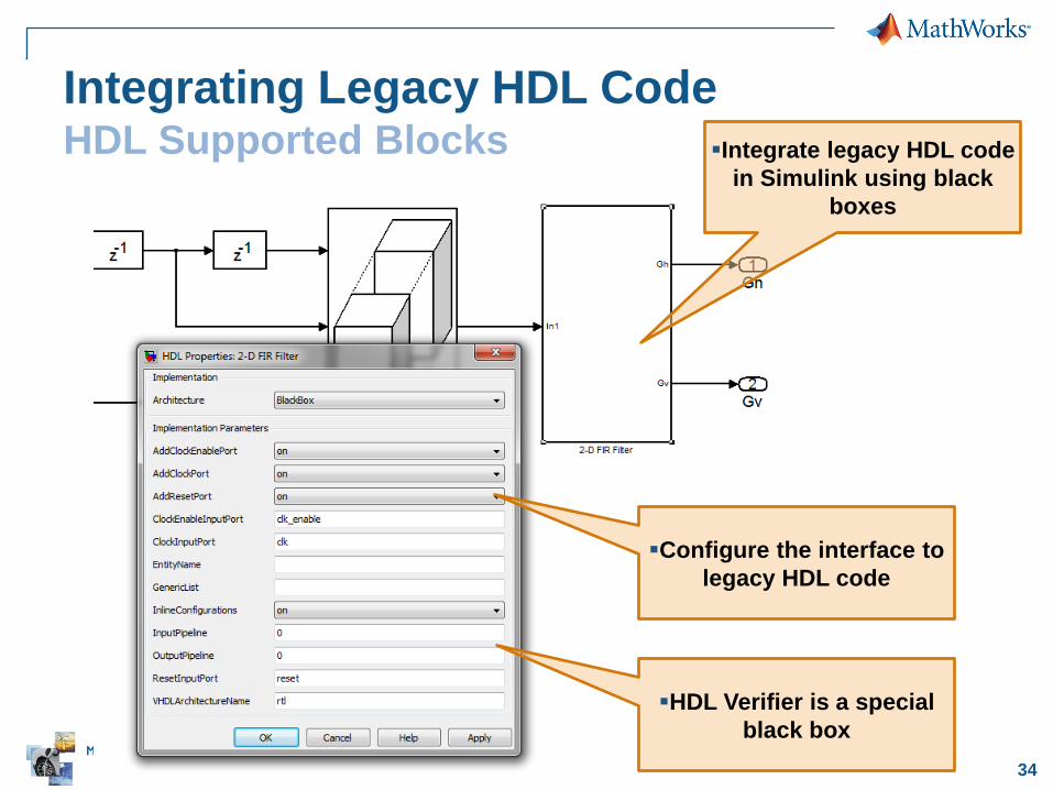
Integrating Legacy HDL Code HDL Supported Blocks Integrate legacy HDL code
in Simulink using black
boxes
Configure the interface to
legacy HDL code
HDL Verifier is a special
black box
35
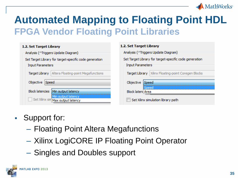
Automated Mapping to Floating Point HDL FPGA Vendor Floating Point Libraries
Support for:
– Floating Point Altera Megafunctions
– Xilinx LogiCORE IP Floating Point Operator
– Singles and Doubles support

36
HDL Code Optimization
37
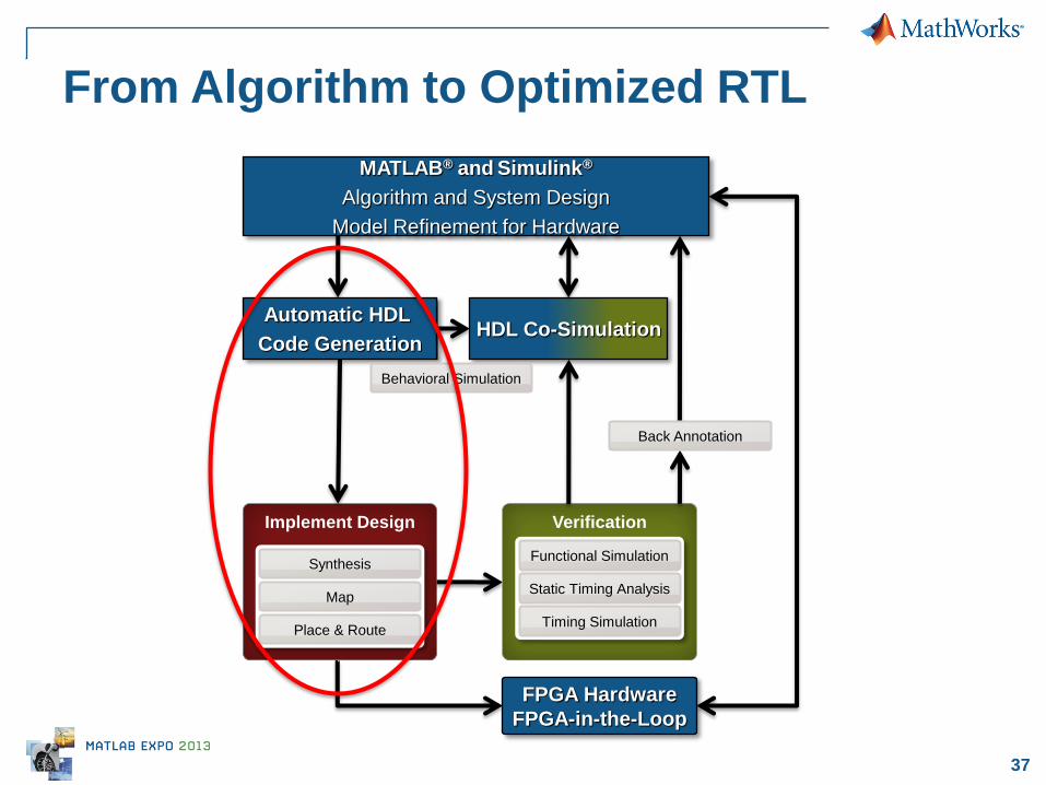
From Algorithm to Optimized RTL
Implement Design
Map
Place & Route
Synthesis
Verification
Static Timing Analysis
Timing Simulation
Functional Simulation
Back Annotation
HDL Co-Simulation
Automatic HDL
Code Generation
Behavioral Simulation
MATLAB® and Simulink®
Algorithm and System Design
Model Refinement for Hardware
FPGA Hardware
FPGA-in-the-Loop

38
Acceptable
Solution
Design Space Exploration S
pe
ed
(n
s)
Area(# LUTS, RAMS)
Speed Constraint
Area Constraint
i5
i2 i1
i3
i4
How can you easily explore
different implementation solutions?
39
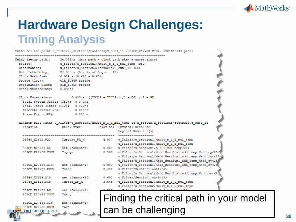
Hardware Design Challenges: Timing Analysis
Finding the critical path in your model
can be challenging

40
Strategies for Speed Improvement
Pipelining
– Input / Output pipeling
– (Hierarchical) Distributed pipelining
– Delay Balancing
Architectural choices, e.g.
– Linear, tree, cascade
– Factored-Canonical-Signed-Digit (FCSD)
– Newton-Raphson Approximation
– CORDIC
41
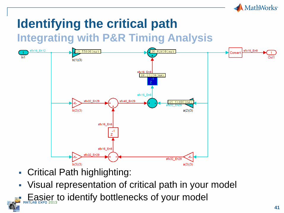
Critical Path highlighting:
Visual representation of critical path in your model
Easier to identify bottlenecks of your model
Identifying the critical path Integrating with P&R Timing Analysis
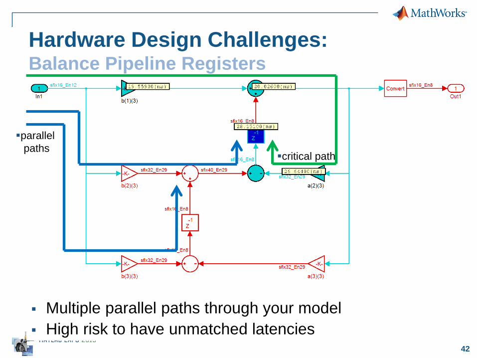
42
Multiple parallel paths through your model
High risk to have unmatched latencies
Hardware Design Challenges: Balance Pipeline Registers
critical path
parallel
paths
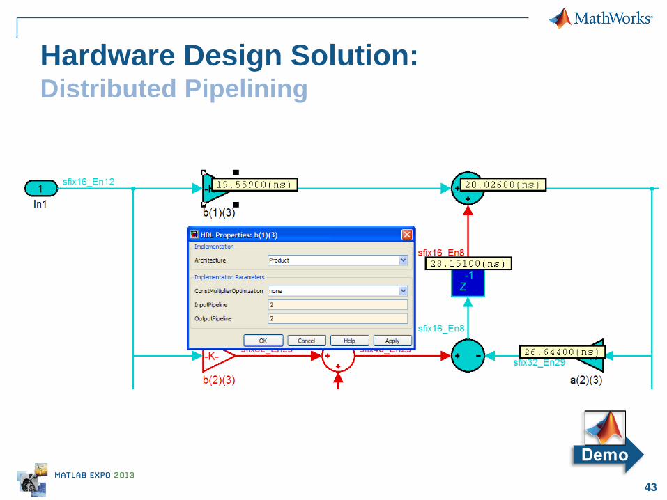
43
Hardware Design Solution: Distributed Pipelining
44
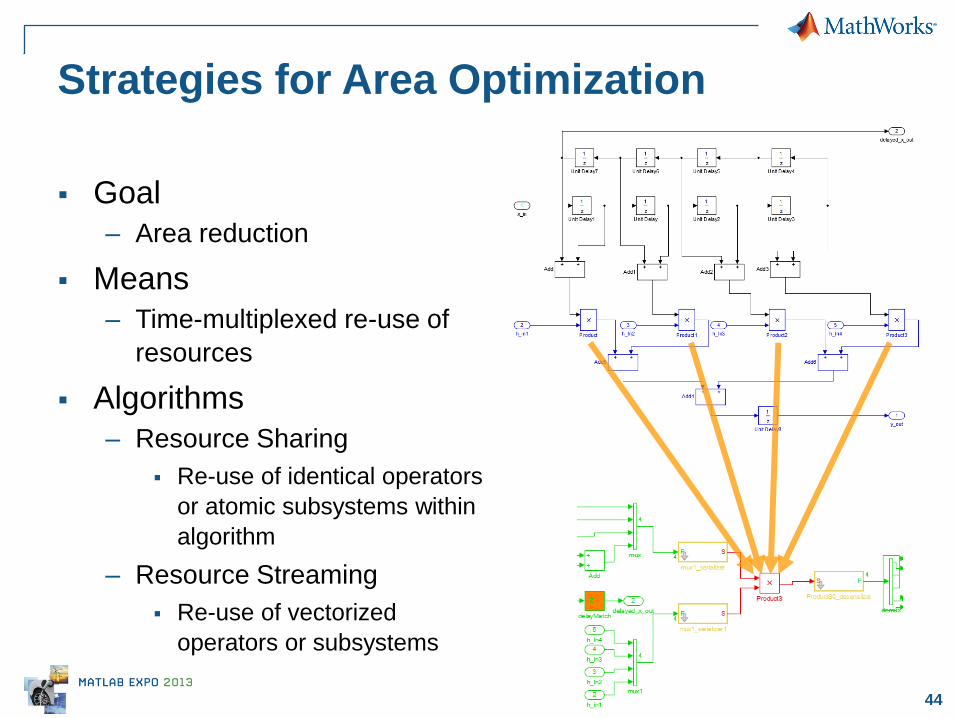
Strategies for Area Optimization
Goal
– Area reduction
Means
– Time-multiplexed re-use of
resources
Algorithms
– Resource Sharing
Re-use of identical operators
or atomic subsystems within
algorithm
– Resource Streaming
Re-use of vectorized
operators or subsystems
45
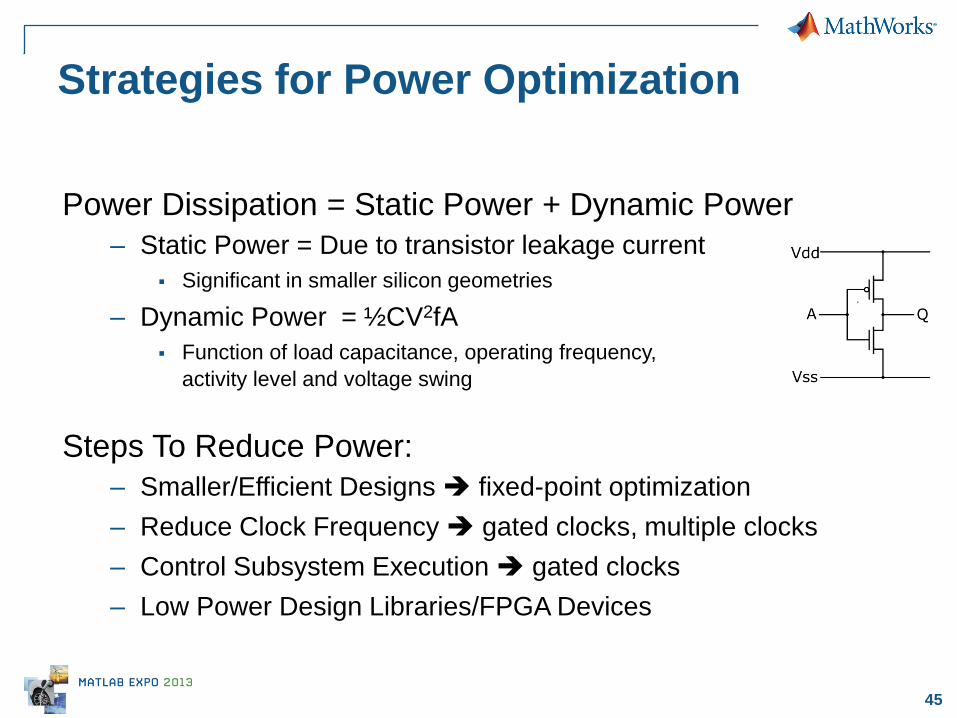
Power Dissipation = Static Power + Dynamic Power
– Static Power = Due to transistor leakage current
Significant in smaller silicon geometries
– Dynamic Power = ½CV2fA
Function of load capacitance, operating frequency,
activity level and voltage swing
Strategies for Power Optimization
Steps To Reduce Power:
– Smaller/Efficient Designs fixed-point optimization
– Reduce Clock Frequency gated clocks, multiple clocks
– Control Subsystem Execution gated clocks
– Low Power Design Libraries/FPGA Devices
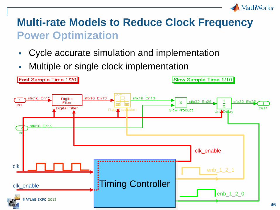
46
clk
clk_enable
enb_1_2_1
enb_1_2_0
clk_enable
Timing Controller
Multi-rate Models to Reduce Clock Frequency
Power Optimization
Cycle accurate simulation and implementation
Multiple or single clock implementation

47
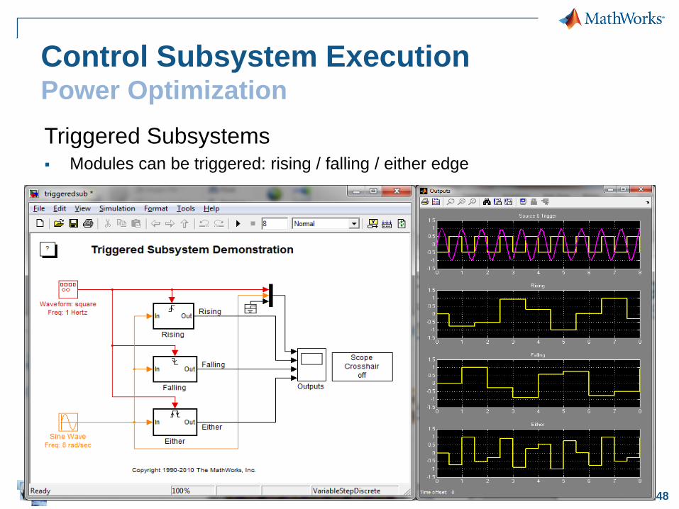
Control Subsystem Execution Power Optimization
Enabled Subsystems Modules can be enabled and disabled
48
Triggered Subsystems Modules can be triggered: rising / falling / either edge
Control Subsystem Execution Power Optimization

49
HDL Verification
50
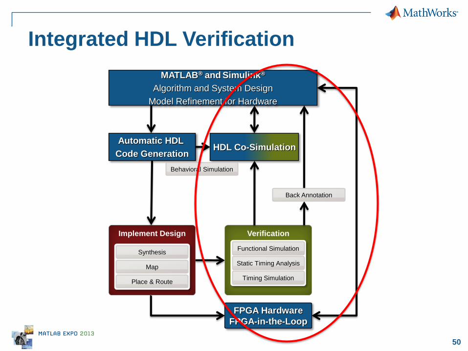
Integrated HDL Verification
Implement Design
Map
Place & Route
Synthesis
Verification
Static Timing Analysis
Timing Simulation
Functional Simulation
Back Annotation
HDL Co-Simulation
Automatic HDL
Code Generation
Behavioral Simulation
MATLAB® and Simulink®
Algorithm and System Design
Model Refinement for Hardware
FPGA Hardware
FPGA-in-the-Loop
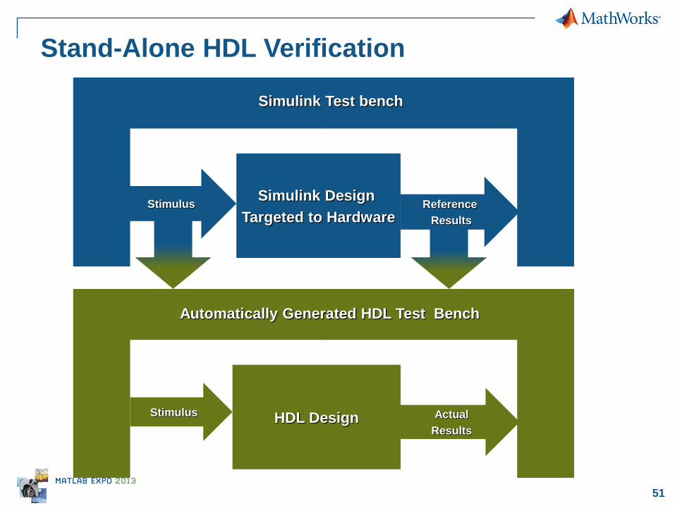
51
Stimulus Reference
Results
Automatically Generated HDL Test Bench
Stimulus Actual
Results HDL Design
Stand-Alone HDL Verification
Simulink Test bench
Simulink Design
Targeted to Hardware
52
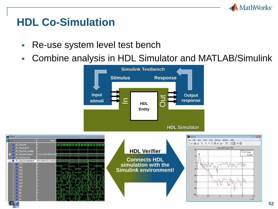
HDL Co-Simulation
HDL Verifier
Connects HDL simulation with the
Simulink environment!
HDL
Entity
In
Ou
t
HDL Simulator
Simulink Testbench
Stimulus Response
Input
stimuli
Output
response
Re-use system level test bench
Combine analysis in HDL Simulator and MATLAB/Simulink
53
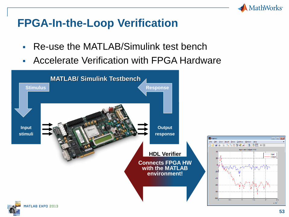
FPGA-In-the-Loop Verification
HDL Verifier
Connects FPGA HW with the MATLAB
environment!
MATLAB/ Simulink Testbench
Input
stimuli
Output
response
Re-use the MATLAB/Simulink test bench
Accelerate Verification with FPGA Hardware
Response Stimulus
54 © 2013 The MathWorks, Inc.
HW/SW Integration on heterogeneous
Systems-on-Chip (SoCs)
55
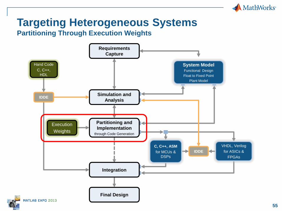
Targeting Heterogeneous Systems Partitioning Through Execution Weights
System Model Functional Design
Float to Fixed Point
Plant Model
C, C++, ASM
for MCUs &
DSPs
IDDE
VHDL, Verilog
for ASICs &
FPGAs
Requirements
Capture
Simulation and
Analysis
Partitioning and
Implementation through Code Generation
Integration
Final Design
Hand Code
C, C++,
HDL
IDDE
Execution
Weights
56
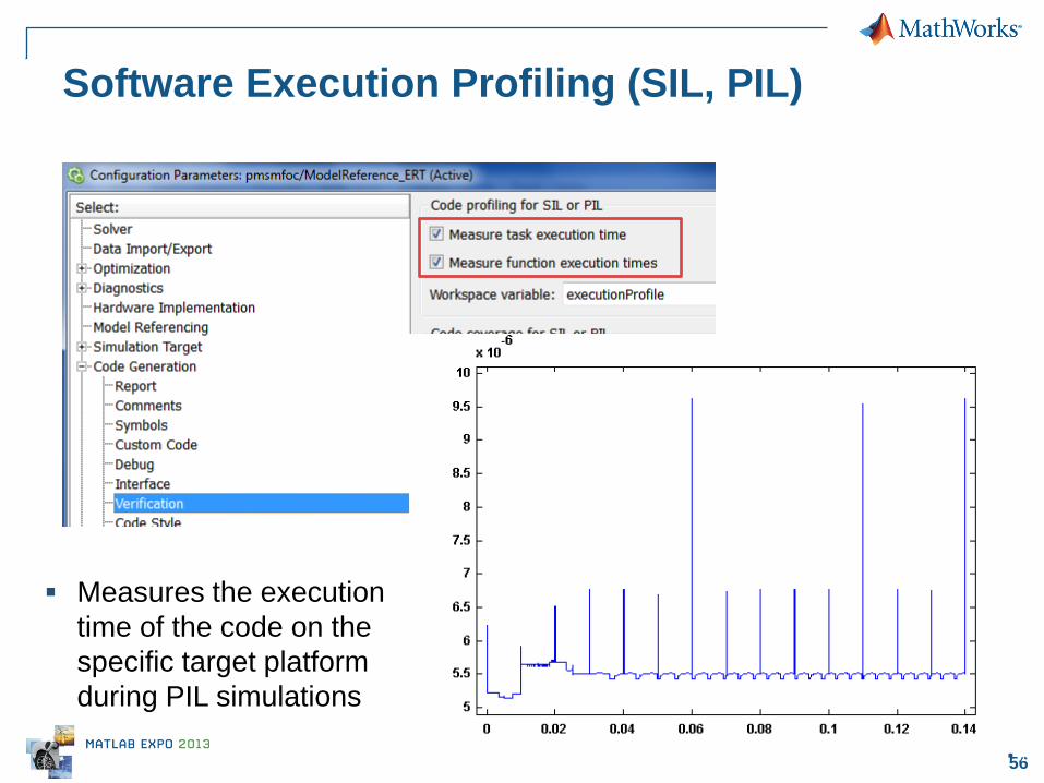
Software Execution Profiling (SIL, PIL)
56
Measures the execution
time of the code on the
specific target platform
during PIL simulations
57
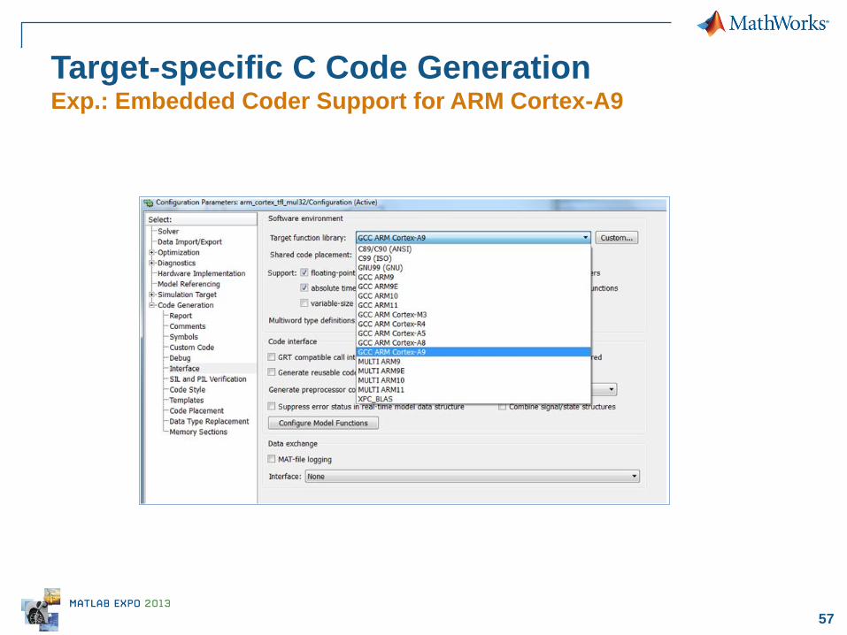
Target-specific C Code Generation Exp.: Embedded Coder Support for ARM Cortex-A9
58
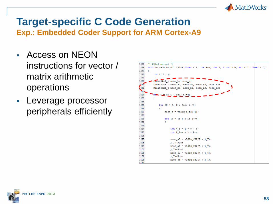
Target-specific C Code Generation Exp.: Embedded Coder Support for ARM Cortex-A9
Access on NEON
instructions for vector /
matrix arithmetic
operations
Leverage processor
peripherals efficiently
59
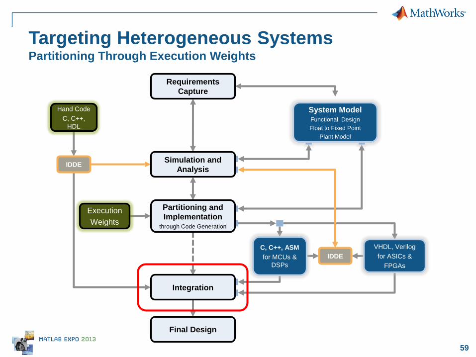
Targeting Heterogeneous Systems Partitioning Through Execution Weights
System Model Functional Design
Float to Fixed Point
Plant Model
C, C++, ASM
for MCUs &
DSPs
IDDE
VHDL, Verilog
for ASICs &
FPGAs
Requirements
Capture
Simulation and
Analysis
Partitioning and
Implementation through Code Generation
Integration
Final Design
Hand Code
C, C++,
HDL
IDDE
Execution
Weights
60
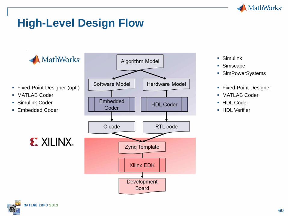
High-Level Design Flow
Simulink
Simscape
SimPowerSystems
Fixed-Point Designer
MATLAB Coder
HDL Coder
HDL Verifier
Fixed-Point Designer (opt.)
MATLAB Coder
Simulink Coder
Embedded Coder

61 © 2013 The MathWorks, Inc.
Summary

62
Best Practice #1:
Enable collaboration by integrating workflows with
Model-Based Design
Best Practice #2:
Reduce development time with Automatic Code (C,
HDL) generation
Best Practice #3:
Reduce verification time with Test Bench Reuse
Things to remember ….
63
INTEGRATION
IMPLEMENTATION
DESIGN
TE
ST
& V
ER
IFIC
AT
ION
REQUIREMENTS
Environment Models
Timing and Control Logic
Digital Models Analog Models
SPICE VHDL, Verilog
TEST
SYSTEM
Analog
Hardware MCU DSP FPGA ASIC
Algorithms
C, C++
RESEARCH RESEARCH
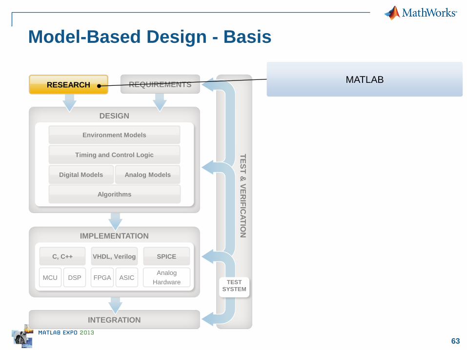
Model-Based Design - Basis
MATLAB
64
INTEGRATION
IMPLEMENTATION
DESIGN
TE
ST
& V
ER
IFIC
AT
ION
Timing and Control Logic
Digital Models Analog Models
SPICE VHDL, Verilog
TEST
SYSTEM
Analog
Hardware MCU DSP FPGA ASIC
C, C++
RESEARCH REQUIREMENTS
VHDL, Verilog
Environment Models
Algorithms
Environment Models
Algorithms
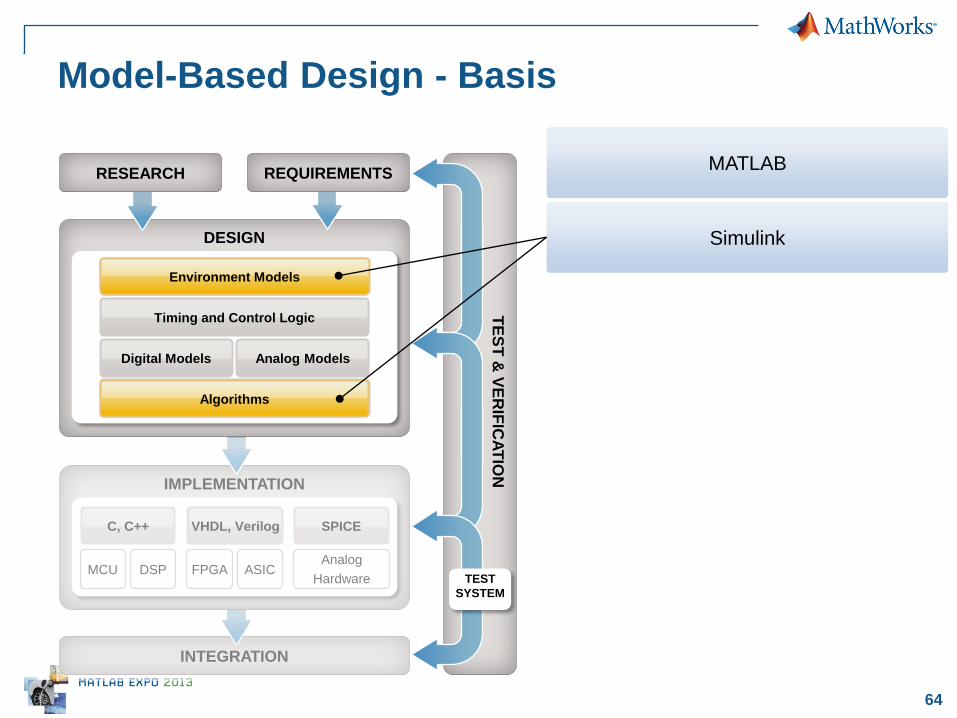
Model-Based Design - Basis
Simulink
MATLAB

65
INTEGRATION
IMPLEMENTATION
DESIGN
TE
ST
& V
ER
IFIC
AT
ION
Timing and Control Logic
Digital Models Analog Models
SPICE VHDL, Verilog
TEST
SYSTEM
Analog
Hardware MCU DSP FPGA ASIC
C, C++
RESEARCH REQUIREMENTS
VHDL, Verilog
Environment Models
Algorithms
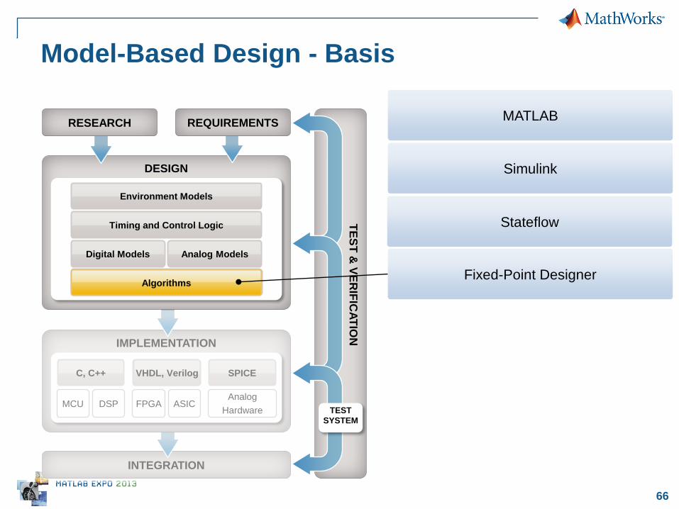
Model-Based Design - Basis
Simulink
MATLAB
Stateflow Timing and Control Logic
66
INTEGRATION
IMPLEMENTATION
DESIGN
TE
ST
& V
ER
IFIC
AT
ION
Timing and Control Logic
Digital Models Analog Models
SPICE VHDL, Verilog
TEST
SYSTEM
Analog
Hardware MCU DSP FPGA ASIC
C, C++
RESEARCH REQUIREMENTS
VHDL, Verilog
Environment Models
Algorithms Algorithms
Model-Based Design - Basis
Simulink
MATLAB
Stateflow
Fixed-Point Designer

67
INTEGRATION
IMPLEMENTATION
DESIGN
TE
ST
& V
ER
IFIC
AT
ION
Timing and Control Logic
Digital Models Analog Models
SPICE VHDL, Verilog
TEST
SYSTEM
Analog
Hardware MCU DSP FPGA ASIC
C, C++
RESEARCH REQUIREMENTS
VHDL, Verilog
Environment Models
Algorithms
Model-Based Design – HDL Code Generation
Simulink
MATLAB
Stateflow
VHDL, Verilog
Fixed-Point Designer Algorithms
Timing and Control Logic
MATLAB Coder & HDL Coder

68
INTEGRATION
IMPLEMENTATION
DESIGN
TE
ST
& V
ER
IFIC
AT
ION
Analog Models
SPICE
TEST
SYSTEM
Analog
Hardware MCU DSP FPGA ASIC
C, C++
RESEARCH REQUIREMENTS
Environment Models
Algorithms
Timing and Control Logic
Digital Models
VHDL, Verilog VHDL, Verilog
Digital Models
Model-Based Design – HDL & FIL Verification
HDL Verifier
MATLAB Coder & HDL Coder
Simulink
MATLAB
Stateflow
Fixed-Point Designer
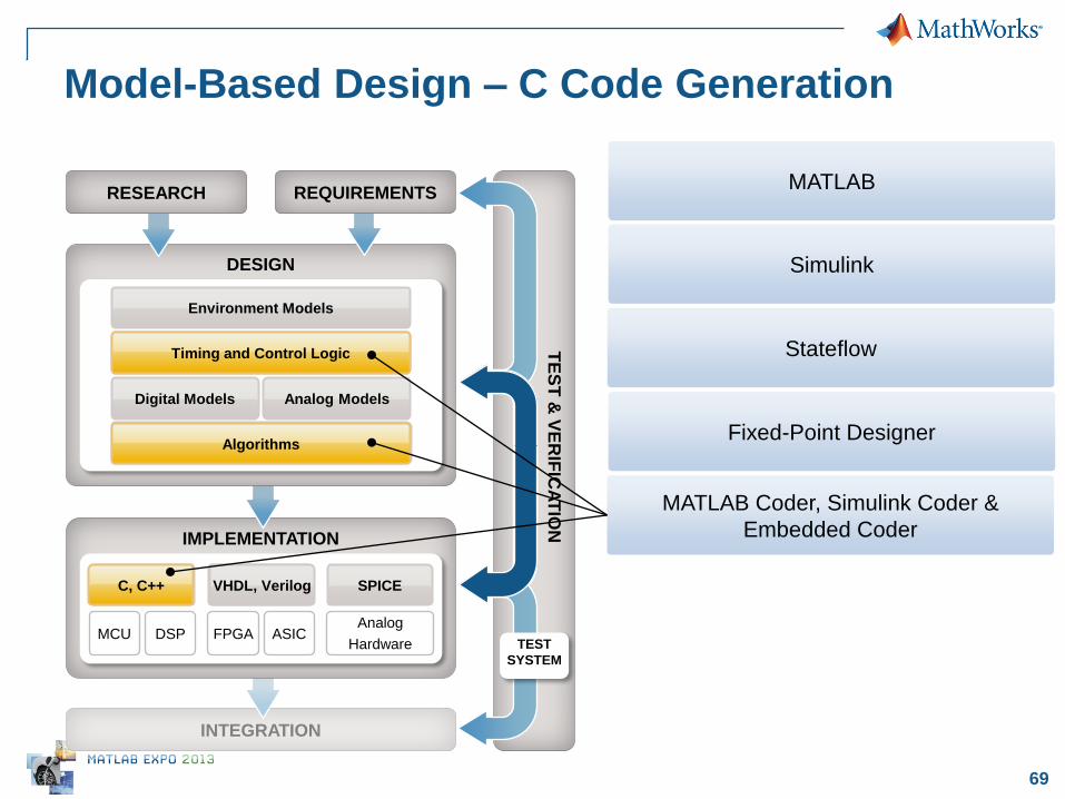
69
INTEGRATION
IMPLEMENTATION
DESIGN
TE
ST
& V
ER
IFIC
AT
ION
Timing and Control Logic
Digital Models Analog Models
SPICE VHDL, Verilog
TEST
SYSTEM
Analog
Hardware MCU DSP FPGA ASIC
C, C++
RESEARCH REQUIREMENTS
VHDL, Verilog
Environment Models
Algorithms
Model-Based Design – C Code Generation
Simulink
MATLAB
Stateflow
C, C++
Fixed-Point Designer Algorithms
Timing and Control Logic
MATLAB Coder, Simulink Coder &
Embedded Coder

70 © 2013 The MathWorks, Inc.
Questions?

71 © 2013 The MathWorks, Inc.
Thank you!


![HW-SW co-Design of an On-Chip IJTAG Dependability Processoressay.utwente.nl/70623/1/[Master Thesis] HW-SW co-Design of an On-Chip IJTAG... · pendability processor. An on-chip IJTAG](https://img.pdfslide.us/doc/110x75/5d31a73188c99342448bf57f/hw-sw-co-design-of-an-on-chip-ijtag-dependability-master-thesis-hw-sw-co-design.jpg)