Embed Size (px)
DESCRIPTION
Model-Based Design for DO-178B R2008b
Citation preview

Model-Based Design for Safety Critical or
Mission Critical DO-178B Applications
Using MathWorks Software Release R2008b
March 3, 2009
The MathWorks Confidential – Subject to Non-
Disclosure Agreement This document is CONFIDENTIAL and cannot be disclosed, disseminated, or distributed
to parties outside The MathWorks or its subsidiaries without written permission from
The MathWorks, Inc.

The MathWorks, Inc.
3 Apple Hill Drive
Natick, MA 01760-2098
© COPYRIGHT 2009 by The MathWorks, Inc.
MATLAB, Simulink, Stateflow, Handle Graphics, Real-Time Workshop, PolySpace and
xPC TargetBox are registered trademarks of The MathWorks, Inc.
Page 1
MathWorks Confidential – subject to Non-Disclosure Agreement
Do not distribute
1 Introduction ................................................................................................................. 5 2 DO-178B Software Lifecycle ..................................................................................... 7
2.1 Table A-1 Planning Process ................................................................................. 8
2.1.1 Software development and integral processes activities are defined ............ 8 2.1.2 Transition criteria, inter-relationships and sequencing among processes are
defined 10 2.1.3 Software life cycle environment is defined ................................................ 10 2.1.4 Additional considerations are addressed ..................................................... 10
2.1.5 Software development standards are defined ............................................. 11 2.1.6 Software plans comply with this document ................................................ 11 2.1.7 Software plans are coordinated ................................................................... 11
2.2 Table A-2 Software Development Process ........................................................ 12 2.2.1 High-level requirements are developed ...................................................... 12 2.2.2 Derived high-level requirements are developed ......................................... 13
2.2.3 Software architecture is developed ............................................................. 13 2.2.4 Low-level requirements are developed ....................................................... 13
2.2.5 Derived low-level requirements are developed .......................................... 13 2.2.6 Source code is developed ............................................................................ 13 2.2.7 Executable Object Code is produced and integrated in the target computer
14 2.3 Table A-3 Verification of Requirements Process .............................................. 15
2.3.1 Software high-level requirements comply with system requirements ........ 16
2.3.2 High-level requirements are accurate and consistent.................................. 16
2.3.3 High-level requirements are compatible with the target computer ............. 16 2.3.4 High-level requirements are verifiable ....................................................... 17
2.3.5 High-level requirements conform to standards ........................................... 17 2.3.6 High-level requirements are traceable to system requirements .................. 17 2.3.7 Algorithms are accurate .............................................................................. 17
2.4 Table A-4 Verification of Design Process ......................................................... 18 2.4.1 Low-level requirements comply with high-level requirements .................. 20
2.4.2 Low-level requirements are accurate and consistent .................................. 20 2.4.3 Low-level requirements are compatible with the target computer ............. 20
2.4.4 Low-level requirements are verifiable ........................................................ 20 2.4.5 Low-level requirements conform to standards ........................................... 21
2.4.6 Low-level requirements are traceable to high-level requirements .............. 21 2.4.7 Algorithms are accurate .............................................................................. 21 2.4.8 Software architecture is compatible with high-level requirements ............. 22 2.4.9 Software architecture is consistent.............................................................. 22 2.4.10 Software architecture is compatible with the target computer.................... 22
2.4.11 Software architecture is verifiable .............................................................. 23 2.4.12 Software architecture conforms to standards .............................................. 23 2.4.13 Software partitioning integrity is confirmed ............................................... 23
2.5 Table A-5 Verification of Coding and Integration Process................................ 24 2.5.1 Source code complies with low-level requirements ................................... 24
Page 2
MathWorks Confidential – subject to Non-Disclosure Agreement
Do not distribute
2.5.2 Source code complies with software architecture ....................................... 25 2.5.3 Source code is verifiable ............................................................................. 25 2.5.4 Source code conforms to standards............................................................. 25 2.5.5 Source code is traceable to low-level requirements .................................... 25
2.5.6 Source code is accurate and consistent ....................................................... 25 2.5.7 Output of software integration process is complete and correct ................. 25
2.6 Table A-6 Testing of Outputs of Integration Process ........................................ 26 2.6.1 Executable Object Code complies with high-level requirements ............... 27 2.6.2 Executable Object Code is robust with high-level requirements ................ 27
2.6.3 Executable Object Code complies with low-level requirements ................ 27 2.6.4 Executable Object Code is robust with low-level requirements ................. 28 2.6.5 Executable Object Code is compatible with target computer ..................... 28
2.7 Table A-7 Verification of Verification Process Results ..................................... 29 2.7.1 Test procedures are correct ......................................................................... 29 2.7.2 Test results are correct and discrepancies explained .................................. 30
2.7.3 Test coverage of high-level requirements is achieved ................................ 30 2.7.4 Test coverage of low-level requirements is achieved ................................. 30
2.7.5 Test coverage of software structure (modified condition/decision) is
achieved .................................................................................................................... 30 2.7.6 Test coverage of software structure (decision coverage) is achieved ......... 30
2.7.7 Test coverage of software structure (statement coverage) is achieved ....... 31 2.7.8 Test coverage of software structure (data coupling and control) is achieved
31
2.8 Table A-8 Software Configuration Management Process.................................. 32
2.8.1 Configuration items are identified .............................................................. 32 2.8.2 Baselines and traceability are established ................................................... 33
2.8.3 Problem reporting, change control, change review, and configuration status
accounting are established ........................................................................................ 33 2.8.4 Archive, retrieval, and release are established ............................................ 33
2.8.5 Software load control is established ........................................................... 33 2.8.6 Software life cycle environment control is established .............................. 33
2.9 Table A-9 Software Quality Assurance Process ................................................ 34 2.9.1 Assurance is obtained that software development and integral processes
comply with approved software plans and standards ............................................... 34 2.9.2 Assurance is obtained that transition criteria for the software life cycle
processes are satisfied ............................................................................................... 34 2.9.3 Software conformity review is completed .................................................. 34
2.10 Table A-10 Certification Liaison Process ...................................................... 35 2.10.1 Communication and understanding between the applicant and the
certification authority is established ......................................................................... 35
2.10.2 The means of compliance is proposed and agreement with the Plan for
Software Aspects of Certification is obtained .......................................................... 35 2.10.3 Compliance substantiation is provided ....................................................... 35
3 Model Architecture Considerations .......................................................................... 36 3.1 Use of Atomic Subsystems ................................................................................ 36
Page 3
MathWorks Confidential – subject to Non-Disclosure Agreement
Do not distribute
3.2 Use of Model Reference ..................................................................................... 37 3.3 Input and Output Hardware Interfaces ............................................................... 40 3.4 Test Harnesses .................................................................................................... 42
4 Solver Considerations for Safety Critical or Mission Critical Systems .................... 44
5 Data Import/Export Considerations for Safety Critical or Mission Critical Systems47 6 Optimization Considerations for Safety Critical or Mission Critical Systems ......... 48 7 Model Diagnostic Considerations for Safety Critical or Mission Critical Systems . 52
7.1 Solver Diagnostics.............................................................................................. 52 7.2 Sample Time Diagnostics................................................................................... 55
7.3 Data Validity Diagnostics .................................................................................. 57 7.4 Type Conversion Diagnostics ............................................................................ 61 7.5 Connectivity Diagnostics ................................................................................... 63
7.6 Compatibility Diagnostics .................................................................................. 65 7.7 Model Reference Diagnostics ............................................................................ 66 7.8 Saving Diagnostics ............................................................................................. 69
8 Hardware Implementation Considerations for Safety Critical or Mission Critical
Systems ............................................................................................................................. 71
9 Simulation Target Considerations for Safety Critical or Mission Critical Systems . 72 9.1 Simulation Target ............................................................................................... 72 9.2 Symbols .............................................................................................................. 74
9.3 Custom Code ...................................................................................................... 76 10 Code Generator Considerations for Safety Critical or Mission Critical Systems ..... 78
10.1 Real-Time Workshop® Software ................................................................... 78
10.2 Report ............................................................................................................. 81
10.3 Comments ....................................................................................................... 83 10.4 Symbols .......................................................................................................... 85
10.5 Custom Code .................................................................................................. 89 10.6 Debug.............................................................................................................. 91 10.7 Interface .......................................................................................................... 92
10.8 Code Style....................................................................................................... 95 10.9 Templates........................................................................................................ 96
10.10 Data Placement ............................................................................................... 97 10.11 Data Type Replacement .................................................................................. 98
10.12 Memory Sections ............................................................................................ 99 11 Block Selection Considerations for Safety Critical or Mission Critical Systems ... 100
11.1 General Guidelines ....................................................................................... 100 11.2 Specific Blocks of Concern .......................................................................... 100
12 Block Setting and Data Type Considerations for Safety Critical or Mission Critical
Systems ........................................................................................................................... 101 12.1 General Block Data Type Settings ............................................................... 101
12.2 Saturate on Integer Overflow Settings .......................................................... 104 12.3 Abs Block ..................................................................................................... 105 12.4 Data Store Blocks ......................................................................................... 106 12.5 For Iterator Subsystem.................................................................................. 106 12.6 Inport and Outport Blocks ............................................................................ 106
Page 4
MathWorks Confidential – subject to Non-Disclosure Agreement
Do not distribute
12.7 Math Function Block .................................................................................... 107 12.8 Merge Block ................................................................................................. 108 12.9 Product Block ............................................................................................... 108 12.10 Relational Operator Blocks .......................................................................... 109
12.11 Triggered Subsystem .................................................................................... 109 12.12 While Iterator Subsystem ............................................................................. 109
13 Stateflow® Software Considerations for Safety Critical or Mission Critical Systems
110 13.1 Chart Settings ............................................................................................... 110
13.2 Stateflow® Software Debugger Settings ...................................................... 111 13.3 Truth Table Settings ..................................................................................... 112 13.4 Chart Commenting ....................................................................................... 112
13.5 Transition Paths Crossing Parallel State Boundaries ................................... 113 13.6 Transition Paths Looping Out of the Parent of Source/Destination Objects 114 13.7 Transition Paths Passing Through a State .................................................... 114
13.8 Flow-Graph Backup ..................................................................................... 116 13.9 Recursive Graphical Functions ..................................................................... 117
14 Run-Time Library Considerations for Safety Critical or Mission Critical Systems118 14.1 Runtime Libraries ......................................................................................... 118 14.2 MISRA-C Violations .................................................................................... 118
Page 5
MathWorks Confidential – subject to Non-Disclosure Agreement
Do not distribute
1 Introduction The purpose of this document is to provide approaches for applying the MathWorks
Model-Based Design products to safety critical or mission critical systems that must meet
DO-178B1 objectives for certification. Approaches presented in this document are
provided as recommendations, but are not the only methods that could be used in meeting
DO-178B objectives for certification. These guidelines may also be applied to safety
critical or mission critical systems that do not have to meet the objectives of DO-178B,
but this document does assume that the software lifecycle follows that standard.
DO-178B defines five software levels: A, B, C, D and E. Systems being developed to
levels A or B would certainly fall into the category of safety critical or mission critical,
because failures of these systems could result in loss of life. Systems being developed to
level C may result in increased crew workload and a reduction in safety and should
therefore provide a high degree of reliability. The recommendations in this document are
applicable to systems being developed to levels A, B and C.
This document does not discuss custom S-Functions, device drivers or Embedded
MATLAB® functions that are produced by the developer using manual coding
techniques. Hand written code that is called by auto-generated code will have to meet all
of the lifecycle requirements of DO-178B. Considerations for Embedded MATLAB®
functions may be added to this document in the future.
It is not the purpose of this document to provide modeling style guidelines. The MAAB
Style Guidelines document is available on MATLAB® Central at the following link.
http://www.mathworks.com/support/solutions/data/1-4SHZMF.html?product=SL&solution=1-4SHZMF
The motivation of the MAAB Style Guidelines, as described in that document, is:
System integration without problems
Clean interfaces
Uniform appearance of models, code and documentation
Reusable models
1 “Software Considerations in Airborne Systems and Equipment Certification,” Document No. RTCA/DO-
178B, December 1, 1992, Prepared by SC-167
Disclaimer: While adhering to the recommendations in this document will reduce
the risk that an error is introduced in the software development process and is not
detected, it is not a guarantee that the system being developed will be safe.
Conversely, if the recommendations in this document are not followed, it does not
mean that the system being developed will be unsafe.
Page 6
MathWorks Confidential – subject to Non-Disclosure Agreement
Do not distribute
Readable models
Hassle-free exchange of models
Avoidance of legacies
A clean process
Professional documentation
Understandable presentations
Fast software changes
Cooperation with subcontractors
Handing over of (research or predevelopment) projects (to product development)
The MAAB Style Guidelines document is considered to be complementary to this
document and may be used as a starting point for defining modeling standards for a
safety critical or mission critical development program.
This document is current with MathWorks software Release R2008b.
Page 7
MathWorks Confidential – subject to Non-Disclosure Agreement
Do not distribute
2 DO-178B Software Lifecycle The following processes make up the DO-178B software lifecycle:
Planning process
Software development process
Verification of requirements process
Verification of design process
Verification of coding and integration process
Testing of outputs of integration process
Verification of verification process results
Software configuration management process
Software quality assurance process
Certification liaison process
There are objectives that must be met for each of the lifecycle stages defined in DO-178B.
These objectives are summarized in Appendix A of DO-178B in the form of tables. The
following sections of this document summarize those tables and provide
recommendations on how the objectives may be met using a Model-Based Design
process. Additionally, the potential usage of available Model-Based Design tools in
achieving the objectives is also included.
Page 8
MathWorks Confidential – subject to Non-Disclosure Agreement
Do not distribute
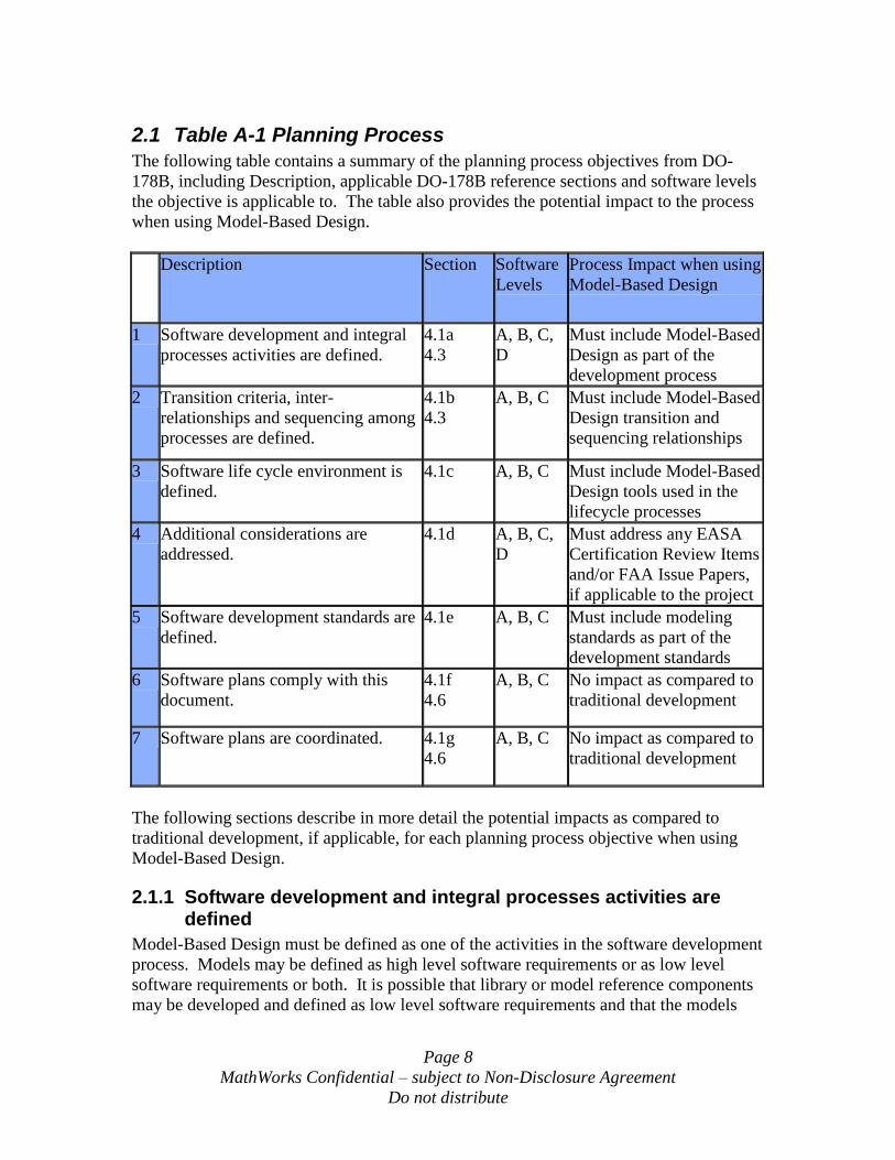
2.1 Table A-1 Planning Process
The following table contains a summary of the planning process objectives from DO-
178B, including Description, applicable DO-178B reference sections and software levels
the objective is applicable to. The table also provides the potential impact to the process
when using Model-Based Design.
Description Section Software
Levels
Process Impact when using
Model-Based Design
1 Software development and integral
processes activities are defined.
4.1a
4.3
A, B, C,
D
Must include Model-Based
Design as part of the
development process
2 Transition criteria, inter-
relationships and sequencing among
processes are defined.
4.1b
4.3
A, B, C Must include Model-Based
Design transition and
sequencing relationships
3 Software life cycle environment is
defined.
4.1c A, B, C Must include Model-Based
Design tools used in the
lifecycle processes
4 Additional considerations are
addressed.
4.1d A, B, C,
D
Must address any EASA
Certification Review Items
and/or FAA Issue Papers,
if applicable to the project
5 Software development standards are
defined.
4.1e A, B, C Must include modeling
standards as part of the
development standards
6 Software plans comply with this
document.
4.1f
4.6
A, B, C No impact as compared to
traditional development
7 Software plans are coordinated. 4.1g
4.6
A, B, C No impact as compared to
traditional development
The following sections describe in more detail the potential impacts as compared to
traditional development, if applicable, for each planning process objective when using
Model-Based Design.
2.1.1 Software development and integral processes activities are defined
Model-Based Design must be defined as one of the activities in the software development
process. Models may be defined as high level software requirements or as low level
software requirements or both. It is possible that library or model reference components
may be developed and defined as low level software requirements and that the models
Page 9
MathWorks Confidential – subject to Non-Disclosure Agreement
Do not distribute
that these components are used in to provide full functionality may be defined as high
level software requirements. Three different scenarios will be described in this section.
Scenario 1 – Models developed at the system level are used to generate code
directly
Under this scenario, high level system requirements allocated to system design are
in the form of textual requirements. The models are developed during the system
design process and allocated to software. The models become both the high and
low level software requirements. The models must meet predefined standards and
must be adequately detailed such that code can be generated directly from the
models. As a part of the development process, a predefined set of library blocks
and/or reusable reference models may be designed for use by the systems
engineers. For this case the requirements for the library blocks and reference
models may be considered to be derived software requirements, since they do not
trace to the higher level requirements.
Under this scenario, the verification objectives from tables A-3 and A-4 would be
combined and applied to the single model.
Scenario 2 – Models developed at the system level are not used directly to
generate code
Under this scenario, high level system requirements allocated to system design are
in the form of textual requirements. The models are developed during the system
design process and allocated to software. These models become the high level
software requirements but they are not detailed enough to generate code directly.
An example case of this type of model would be a Simulink diagram that used
continuous time blocks which are not appropriate for embedded real-time code.
The software engineering process would take these models and modify them and
add detail as necessary prior to code generation. These modified models would
then become the low level software requirements.
Under this scenario, the verification objectives from table A-3 would be applied
to the high level model and the objectives from table A-4 would be applied to the
low level model.
Scenario 3 – System level textual requirements are allocated to software
Under this scenario, the system level requirements and design allocated to
software are in the form of textual high level software requirements. The models
are developed as part of the software engineering process and are detailed enough
to generate code. In this case the models are the low level software requirements.

Page 10
MathWorks Confidential – subject to Non-Disclosure Agreement
Do not distribute
Under this scenario, the verification objectives from table A-3 would be applied
to the high level textual requirements and the objectives from table A-4 would be
applied to the model.
Change control and configuration management of the models must be addressed in the
planning process.
2.1.2 Transition criteria, inter-relationships and sequencing among processes are defined
The stage at which Model-Based Design begins must be defined, this will typically be at
the point where the higher level requirements (either system requirements or high level
software requirements) have been developed, configured and approved.
The stage at which code is generated must be defined, this will typically be at the point
that the models have been developed, configured and approved. The steps necessary to
approve the models as complete and correct must be defined and may include: reviews of
the model, simulation testing of the model, static analysis of the model and dynamic
analysis of the model.
2.1.3 Software life cycle environment is defined
Model-Based Design tools that will be used in the development and verification
processes must be defined. These may include tools such as MATLAB®, Simulink®,
Stateflow®, Stateflow® Coder, Real-Time Workshop®, Real-Time Workshop®
Embedded Coder, Simulink® Verification and Validation, SystemTest, MATLAB®
Report Generator and Simulink® Report Generator software.
2.1.4 Additional considerations are addressed
If any Model-Based Design tools will be qualified, either as development or verification
tools, then each of the tools to be qualified must be identified and the tool qualification
activities must be defined.
It is typical for the Federal Aviation Administration (FAA) to provide an Issue Paper (IP),
or for European Aviation Safety Agency (EASA) to provide a Certification Review Item
(CRI), when Model-Based Design is used on a program. Items in the program-specific IP
and/or CRI will need to be addressed during planning. There may be requirements to
trace the models to higher level requirements and to trace the code to the models.
Verification of the models and executable object code against the higher level
requirements may also be addressed. For software levels A and B, independence of the
model developer and the test developer may need to be insured as part of the verification
against the higher level requirements. If an automated tool is used to verify the
executable object code against the model, then that tool may have to be shown to be
independent of the automatic code generator and compiler. The use of an automated tool
to verify the executable object code against the model does not eliminate the need to
Page 11
MathWorks Confidential – subject to Non-Disclosure Agreement
Do not distribute
verify the executable object code against the higher level requirements; it may only be
used to supplement the higher level requirements based tests.
2.1.5 Software development standards are defined
Because the models may be mapped to high level requirements, low level requirements or
both (see section 2.1.1), there will need to be modeling standards in place to satisfy the
requirements standards objectives. Compliance to the standards will have to be verified
through the use of tools and/or human reviews.
For Real-Time Workshop® Embedded Coder, MISRA®-C2 coding standards can be used,
with a few minor exceptions. Some constructs in the generated code, such as naming
conventions, can be controlled by the users in order to meet specific customer coding
standards. Compliance to the standards will have to be verified through the use of tools
and/or human reviews.
2.1.6 Software plans comply with this document
A Plan for Software Aspects of Certification must be developed, the same as for
traditional development programs.
2.1.7 Software plans are coordinated
The Plan for Software Aspects of Certification must be configured under change control
and approved by the applicable certification authorities as part of the program, as in a
traditional development process.
2 “MISRA-C:2004 Guidelines for the use of the C language in critical systems,” The Motor Industry
Software Reliability Association, dated October 2004.
Page 12
MathWorks Confidential – subject to Non-Disclosure Agreement
Do not distribute
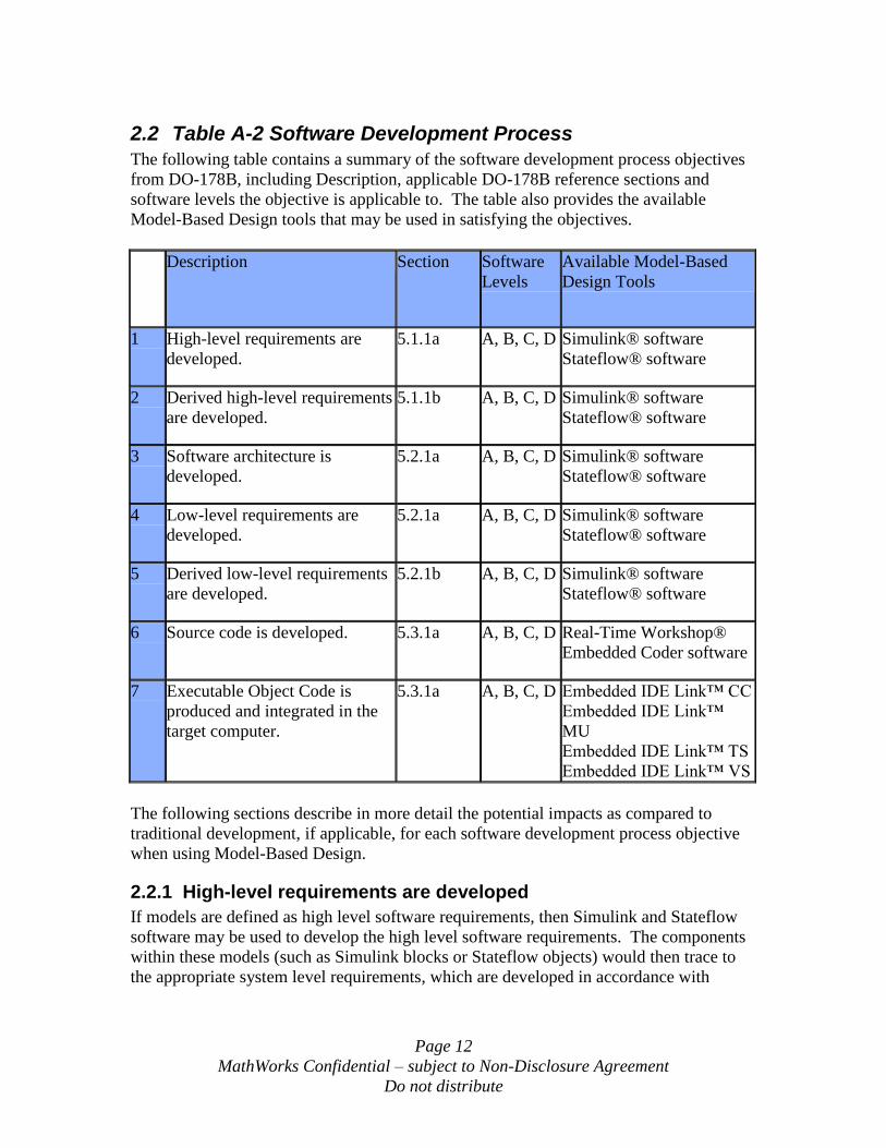
2.2 Table A-2 Software Development Process
The following table contains a summary of the software development process objectives
from DO-178B, including Description, applicable DO-178B reference sections and
software levels the objective is applicable to. The table also provides the available
Model-Based Design tools that may be used in satisfying the objectives.
Description Section Software
Levels
Available Model-Based
Design Tools
1 High-level requirements are
developed.
5.1.1a A, B, C, D Simulink® software
Stateflow® software
2 Derived high-level requirements
are developed.
5.1.1b A, B, C, D Simulink® software
Stateflow® software
3 Software architecture is
developed.
5.2.1a A, B, C, D Simulink® software
Stateflow® software
4 Low-level requirements are
developed.
5.2.1a A, B, C, D Simulink® software
Stateflow® software
5 Derived low-level requirements
are developed.
5.2.1b A, B, C, D Simulink® software
Stateflow® software
6 Source code is developed. 5.3.1a A, B, C, D Real-Time Workshop®
Embedded Coder software
7 Executable Object Code is
produced and integrated in the
target computer.
5.3.1a A, B, C, D Embedded IDE Link™ CC
Embedded IDE Link™
MU
Embedded IDE Link™ TS
Embedded IDE Link™ VS
The following sections describe in more detail the potential impacts as compared to
traditional development, if applicable, for each software development process objective
when using Model-Based Design.
2.2.1 High-level requirements are developed
If models are defined as high level software requirements, then Simulink and Stateflow
software may be used to develop the high level software requirements. The components
within these models (such as Simulink blocks or Stateflow objects) would then trace to
the appropriate system level requirements, which are developed in accordance with
Page 13
MathWorks Confidential – subject to Non-Disclosure Agreement
Do not distribute
ARP47543. The models should be developed in accordance with the modeling standards
defined during the planning process.
2.2.2 Derived high-level requirements are developed
If models are defined as high level software requirements, then any Simulink or Stateflow
components that do not trace to the system requirements would be identified as derived
requirements and these would be provided to the safety assessment process.
2.2.3 Software architecture is developed
Architecture of individual software modules may be defined by the Simulink and
Stateflow models, including sequencing and interfacing of the various elements within
the models. If model reference capability is used, then the model dependency viewer
may be used to document the architecture of the software modules that are integrated
using this capability.
The higher level architecture of how the Model-Based Design generated code interfaces
to other code within the system must be defined separately. This may include interface to
the real-time operating system (RTOS), calling sequence for the code generated from the
Model-Based Design and data interface to other code modules.
2.2.4 Low-level requirements are developed
If models are defined as low level software requirements, then Simulink and Stateflow
may be used to develop the low level software requirements. The components within
these models would then trace to the appropriate high level software requirements. The
models should be developed in accordance with the modeling standards defined during
the planning process.
If the models are defined as high level software requirements, and source code will be
generated directly from those models, then this objective does not apply.
2.2.5 Derived low-level requirements are developed
If models are defined as low level software requirements, then any Simulink or Stateflow
components that do not trace to the high level software requirements would be identified
as derived requirements and these would be provided to the safety assessment process.
If the models are defined as high level software requirements, then it is possible that
library components or reusable model reference functions may be considered to be
derived low level requirements.
2.2.6 Source code is developed
Real-Time Workshop® Embedded Coder may be used to generate the source code from
the model. The source code can trace to the model components through the use of
3 “Certification Considerations for Highly –Integrated or Complex Aircraft Systems,” Document No. SAE
ARP4754, dated November 1996, developed by SAE International.
Page 14
MathWorks Confidential – subject to Non-Disclosure Agreement
Do not distribute
appropriate commenting options described later in this document. The source code can be
generated in accordance with MISRA-C standards, with some exceptions, using
appropriate modeling standards.
2.2.7 Executable Object Code is produced and integrated in the target computer
The generated source code may be compiled, linked and the executable object code
automatically downloaded to a target processor or DSP using Embedded IDE Link™ CC,
Embedded IDE Link™ MU, Embedded IDE Link™ TS, or Embedded IDE Link™ VS.
Alternatively, the generated source code may be compiled and linked using standard
compilers/linkers. Real-Time Workshop® Embedded Coder may generate a make file
for use by the compiler or this may be developed manually. The executable object code
is then loaded onto the target computer.
Page 15
MathWorks Confidential – subject to Non-Disclosure Agreement
Do not distribute
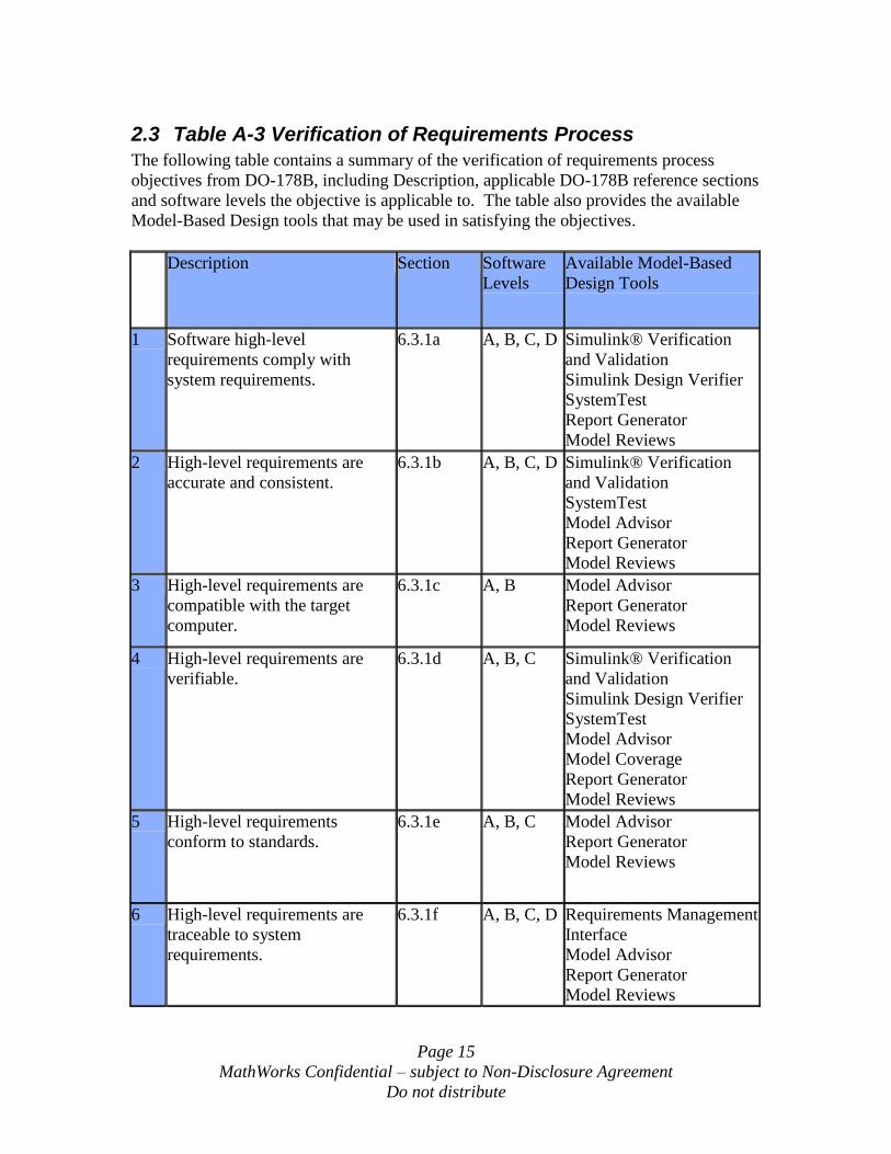
2.3 Table A-3 Verification of Requirements Process
The following table contains a summary of the verification of requirements process
objectives from DO-178B, including Description, applicable DO-178B reference sections
and software levels the objective is applicable to. The table also provides the available
Model-Based Design tools that may be used in satisfying the objectives.
Description Section Software
Levels
Available Model-Based
Design Tools
1 Software high-level
requirements comply with
system requirements.
6.3.1a A, B, C, D Simulink® Verification
and Validation
Simulink Design Verifier
SystemTest
Report Generator
Model Reviews
2 High-level requirements are
accurate and consistent.
6.3.1b A, B, C, D Simulink® Verification
and Validation
SystemTest
Model Advisor
Report Generator
Model Reviews
3 High-level requirements are
compatible with the target
computer.
6.3.1c A, B Model Advisor
Report Generator
Model Reviews
4 High-level requirements are
verifiable.
6.3.1d A, B, C Simulink® Verification
and Validation
Simulink Design Verifier
SystemTest
Model Advisor
Model Coverage
Report Generator
Model Reviews
5 High-level requirements
conform to standards.
6.3.1e A, B, C Model Advisor
Report Generator
Model Reviews
6 High-level requirements are
traceable to system
requirements.
6.3.1f A, B, C, D Requirements Management
Interface
Model Advisor
Report Generator
Model Reviews
Page 16
MathWorks Confidential – subject to Non-Disclosure Agreement
Do not distribute
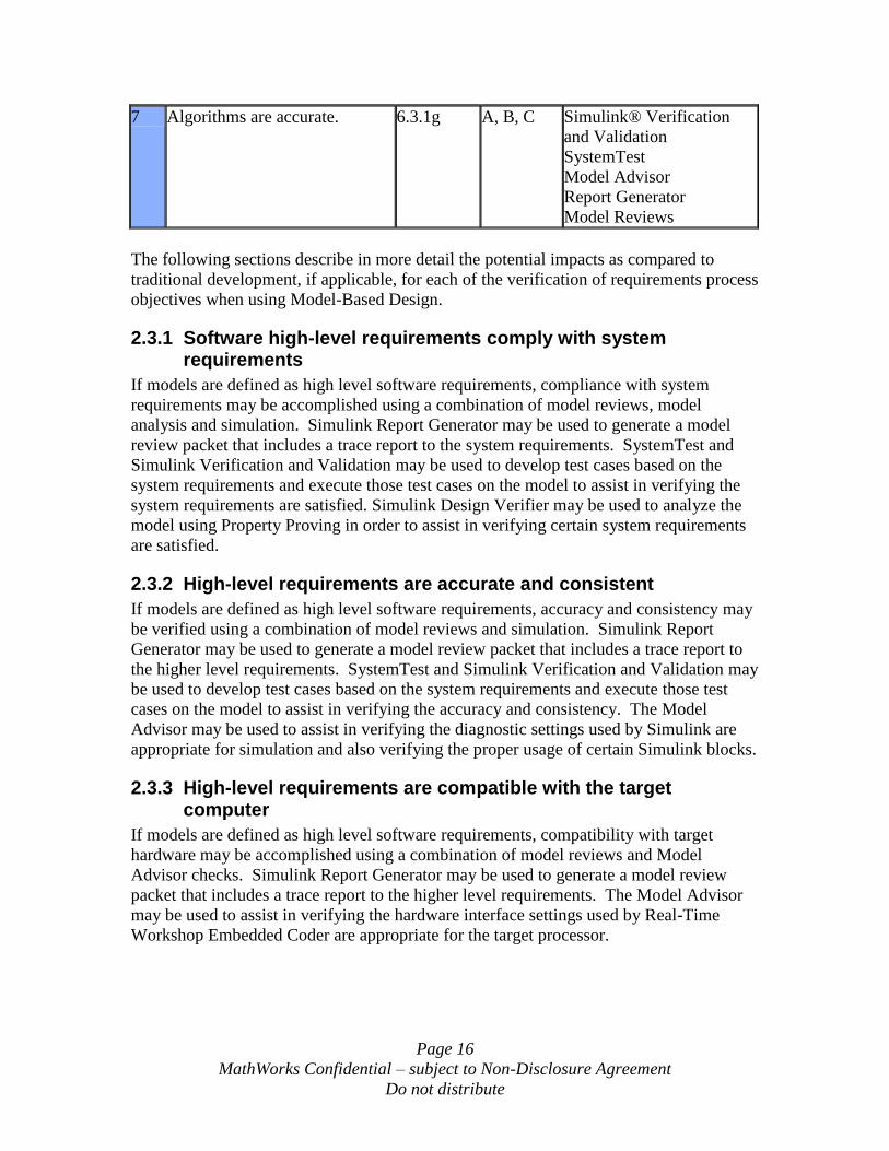
7 Algorithms are accurate. 6.3.1g A, B, C Simulink® Verification
and Validation
SystemTest
Model Advisor
Report Generator
Model Reviews
The following sections describe in more detail the potential impacts as compared to
traditional development, if applicable, for each of the verification of requirements process
objectives when using Model-Based Design.
2.3.1 Software high-level requirements comply with system requirements
If models are defined as high level software requirements, compliance with system
requirements may be accomplished using a combination of model reviews, model
analysis and simulation. Simulink Report Generator may be used to generate a model
review packet that includes a trace report to the system requirements. SystemTest and
Simulink Verification and Validation may be used to develop test cases based on the
system requirements and execute those test cases on the model to assist in verifying the
system requirements are satisfied. Simulink Design Verifier may be used to analyze the
model using Property Proving in order to assist in verifying certain system requirements
are satisfied.
2.3.2 High-level requirements are accurate and consistent
If models are defined as high level software requirements, accuracy and consistency may
be verified using a combination of model reviews and simulation. Simulink Report
Generator may be used to generate a model review packet that includes a trace report to
the higher level requirements. SystemTest and Simulink Verification and Validation may
be used to develop test cases based on the system requirements and execute those test
cases on the model to assist in verifying the accuracy and consistency. The Model
Advisor may be used to assist in verifying the diagnostic settings used by Simulink are
appropriate for simulation and also verifying the proper usage of certain Simulink blocks.
2.3.3 High-level requirements are compatible with the target computer
If models are defined as high level software requirements, compatibility with target
hardware may be accomplished using a combination of model reviews and Model
Advisor checks. Simulink Report Generator may be used to generate a model review
packet that includes a trace report to the higher level requirements. The Model Advisor
may be used to assist in verifying the hardware interface settings used by Real-Time
Workshop Embedded Coder are appropriate for the target processor.
Page 17
MathWorks Confidential – subject to Non-Disclosure Agreement
Do not distribute
2.3.4 High-level requirements are verifiable
If models are defined as high level software requirements, verifiability may be
accomplished using a combination of model reviews and simulation. Simulink Report
Generator may be used to generate a model review packet that includes a trace report to
the higher level requirements. SystemTest and Simulink Verification and Validation may
be used to develop test cases from the system requirements and execute those test cases
on the model. During execution of these test cases, a Model Coverage Report, a
component of Simulink Verification and Validation, may be generated to assist in
verifying that all requirements are fully verified. The coverage report may assist in
finding conditions and decisions in the model that cannot be reached, thus indicating that
the requirements may not be fully verifiable. Simulink Design Verifier may be used to
identify untestable or unreachable model conditions and decisions using test case
generation, thus indicating that the high level requirements may not be fully verifiable.
The Model Advisor may be used to assist in verifying the proper usage of certain
Simulink blocks and data types.
2.3.5 High-level requirements conform to standards
If models are defined as high level software requirements, conformance to standards may
be accomplished using a combination of model reviews and Model Advisor checks.
Simulink Report Generator may be used to generate a model review packet that includes
a trace report to the higher level requirements. The Model Advisor may verify pre-
defined model standards and may also be customized using an API to perform checks
defined by the user that may be unique for their application.
2.3.6 High-level requirements are traceable to system requirements
If models are defined as high level software requirements, traceability to system
requirements may be accomplished by model reviews that include a report generated by
the Requirements Management Interface, a component of Simulink Verification and
Validation. Simulink Report Generator may be used to generate a model review packet
that includes a trace report to the system requirements. The Model Advisor may be used
to assist in verifying that requirements links are consistent.
2.3.7 Algorithms are accurate
If models are defined as high level software requirements, accuracy of the algorithms
may be verified using a combination of model reviews and simulation. Simulink Report
Generator may be used to generate a model review packet that includes a trace report to
the higher level requirements. SystemTest and Simulink Verification and Validation may
be used to develop test cases from the system requirements and execute those test cases
on the model, thus assisting in verifying the accuracy of the algorithms within the model.
The Model Advisor may be used to assist in verifying the proper usage of certain
Simulink blocks and data types.
Page 18
MathWorks Confidential – subject to Non-Disclosure Agreement
Do not distribute
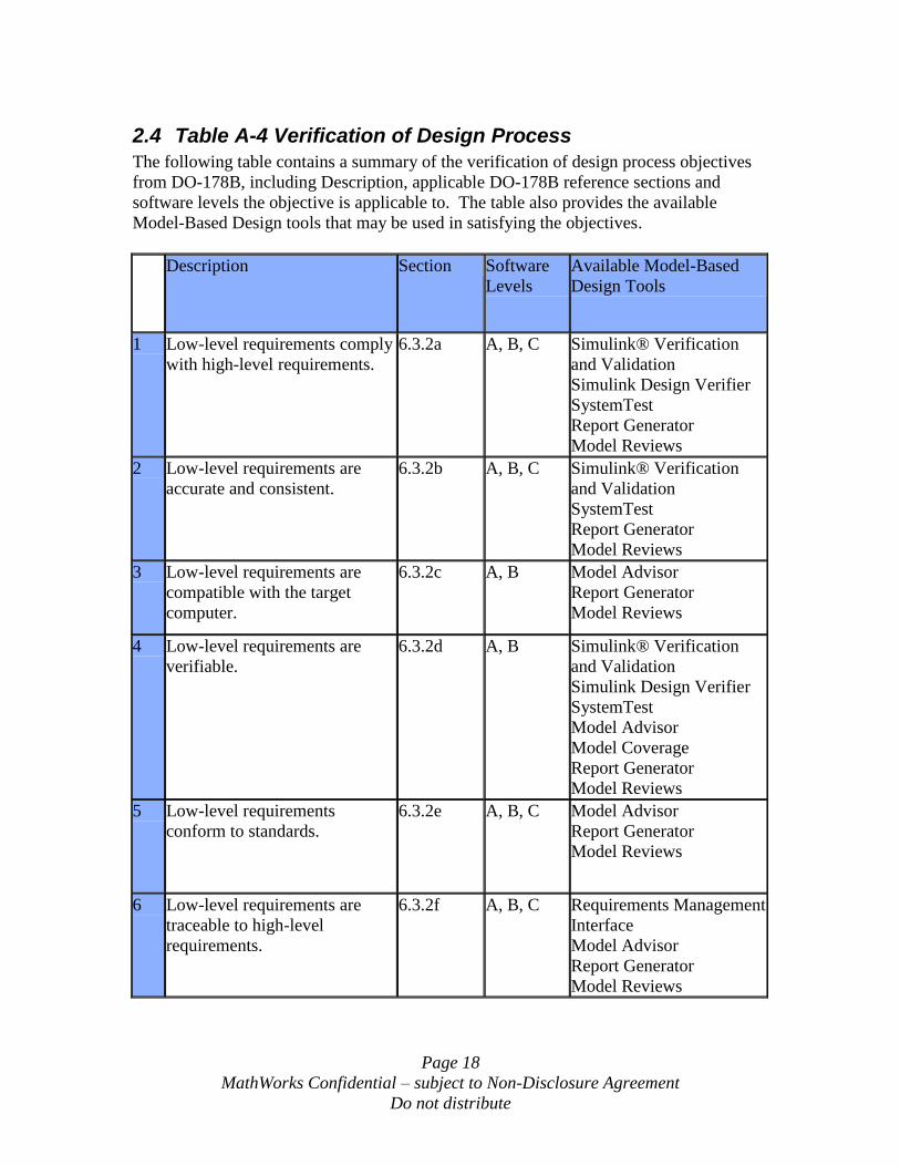
2.4 Table A-4 Verification of Design Process
The following table contains a summary of the verification of design process objectives
from DO-178B, including Description, applicable DO-178B reference sections and
software levels the objective is applicable to. The table also provides the available
Model-Based Design tools that may be used in satisfying the objectives.
Description Section Software
Levels
Available Model-Based
Design Tools
1 Low-level requirements comply
with high-level requirements.
6.3.2a A, B, C Simulink® Verification
and Validation
Simulink Design Verifier
SystemTest
Report Generator
Model Reviews
2 Low-level requirements are
accurate and consistent.
6.3.2b A, B, C Simulink® Verification
and Validation
SystemTest
Report Generator
Model Reviews
3 Low-level requirements are
compatible with the target
computer.
6.3.2c A, B Model Advisor
Report Generator
Model Reviews
4 Low-level requirements are
verifiable.
6.3.2d A, B Simulink® Verification
and Validation
Simulink Design Verifier
SystemTest
Model Advisor
Model Coverage
Report Generator
Model Reviews
5 Low-level requirements
conform to standards.
6.3.2e A, B, C Model Advisor
Report Generator
Model Reviews
6 Low-level requirements are
traceable to high-level
requirements.
6.3.2f A, B, C Requirements Management
Interface
Model Advisor
Report Generator
Model Reviews
Page 19
MathWorks Confidential – subject to Non-Disclosure Agreement
Do not distribute
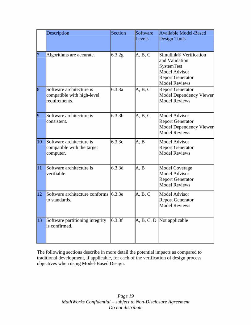
Description Section Software
Levels
Available Model-Based
Design Tools
7 Algorithms are accurate. 6.3.2g A, B, C Simulink® Verification
and Validation
SystemTest
Model Advisor
Report Generator
Model Reviews
8 Software architecture is
compatible with high-level
requirements.
6.3.3a A, B, C Report Generator
Model Dependency Viewer
Model Reviews
9 Software architecture is
consistent.
6.3.3b A, B, C Model Advisor
Report Generator
Model Dependency Viewer
Model Reviews
10 Software architecture is
compatible with the target
computer.
6.3.3c A, B Model Advisor
Report Generator
Model Reviews
11 Software architecture is
verifiable.
6.3.3d A, B Model Coverage
Model Advisor
Report Generator
Model Reviews
12 Software architecture conforms
to standards.
6.3.3e A, B, C Model Advisor
Report Generator
Model Reviews
13 Software partitioning integrity
is confirmed.
6.3.3f A, B, C, D Not applicable
The following sections describe in more detail the potential impacts as compared to
traditional development, if applicable, for each of the verification of design process
objectives when using Model-Based Design.
Page 20
MathWorks Confidential – subject to Non-Disclosure Agreement
Do not distribute
2.4.1 Low-level requirements comply with high-level requirements
If models are defined as low level software requirements, compliance with high level
software requirements may be accomplished using a combination of model reviews,
model analysis and simulation. Simulink Report Generator may be used to generate a
model review packet that includes a trace report to the system requirements. SystemTest
and Simulink Verification and Validation may be used to develop test cases from the high
level requirements and execute those test cases on the model to assist in verifying the
high level requirements are satisfied. Simulink Design Verifier may be used to analyze
the model using Property Proving in order to assist in verifying certain high level
requirements are satisfied.
If the models are defined as high level software requirements, then code may be
generated directly from the high level requirements and this objective does not apply. See
DO-178B, Section 6.1.b for details.
2.4.2 Low-level requirements are accurate and consistent
If models are defined as low level software requirements, accuracy and consistency may
be verified using a combination of model reviews and simulation. Simulink Report
Generator may be used to generate a model review packet that includes a trace report to
the higher level requirements. SystemTest and Simulink Verification and Validation may
be used to develop test cases from the high level requirements and execute those test
cases on the model to assist in verifying the accuracy and consistency. The Model
Advisor may be used to assist in verifying the diagnostic settings used by Simulink are
appropriate for simulation and also verifying the proper usage of certain Simulink blocks.
If the models are defined as high level software requirements, then code may be
generated directly from the high level requirements and this objective does not apply. See
DO-178B, Section 6.1.b for details.
2.4.3 Low-level requirements are compatible with the target computer
If models are defined as low level software requirements, compatibility with target
hardware may be accomplished using a combination of model reviews and Model
Advisor checks. Simulink Report Generator may be used to generate a model review
packet that includes a trace report to the higher level requirements. The Model Advisor
may be used to assist in verifying the hardware interface settings used by Real-Time
Workshop® Embedded Coder are appropriate for the target processor.
If the models are defined as high level software requirements, then code may be
generated directly from the high level requirements and this objective does not apply. See
DO-178B, Section 6.1.b for details.
2.4.4 Low-level requirements are verifiable
If models are defined as low level software requirements, verifiability may be
accomplished using a combination of model reviews and simulation. Simulink Report
Page 21
MathWorks Confidential – subject to Non-Disclosure Agreement
Do not distribute
Generator may be used to generate a model review packet that includes a trace report to
the higher level requirements. SystemTest and Simulink Verification and Validation may
be used to develop test cases from the high level requirements and execute those test
cases on the model. During execution of these test cases, a Model Coverage Report, a
component of Simulink Verification and Validation, may be generated to assist in
verifying that all requirements are fully verified. The coverage report may assist in
finding conditions and decisions in the model that cannot be reached, thus indicating that
the design may not be fully verifiable. Simulink Design Verifier may be used to identify
untestable or unreachable model conditions and decisions using test case generation, thus
indicating that the low level requirements may not be fully verifiable. The Model
Advisor may be used to assist in verifying the proper usage of certain Simulink blocks
and data types.
If the models are defined as high level software requirements, then code may be
generated directly from the high level requirements and this objective does not apply. See
DO-178B, Section 6.1.b for details.
2.4.5 Low-level requirements conform to standards
If models are defined as low level software requirements, conformance to standards may
be accomplished using a combination of model reviews and Model Advisor checks.
Simulink Report Generator may be used to generate a model review packet that includes
a trace report to the higher level requirements. The Model Advisor may be used to verify
pre-defined model standards and may also be customized using an API to perform checks
defined by the user that are unique for their application.
If the models are defined as high level software requirements, then code may be
generated directly from the high level requirements and this objective does not apply. See
DO-178B, Section 6.1.b for details.
2.4.6 Low-level requirements are traceable to high-level requirements
If models are defined as low level software requirements, traceability to high level
software requirements may be accomplished using a combination of model reviews and
the Requirements Management Interface. Simulink Report Generator may be used to
generate a model review packet that includes a trace report to the high level software
requirements. The Model Advisor may be used to assist in verifying that requirements
links are consistent.
If the models are defined as high level software requirements, then code may be
generated directly from the high level requirements and this objective does not apply. See
DO-178B, Section 6.1.b for details.
2.4.7 Algorithms are accurate
If models are defined as low level software requirements, accuracy of the algorithms may
be verified using a combination of model reviews and simulation. Simulink Report
Generator may be used to generate a model review packet that includes a trace report to
Page 22
MathWorks Confidential – subject to Non-Disclosure Agreement
Do not distribute
the higher level requirements. SystemTest and Simulink Verification and Validation may
be used to develop test cases from the high level requirements and execute those test
cases on the model, thus assisting in verifying the accuracy of the algorithms within the
model. The Model Advisor may be used to assist in verifying the proper usage of certain
Simulink blocks and data types.
If the models are defined as high level software requirements, then code may be
generated directly from the high level requirements and this objective does not apply. See
DO-178B, Section 6.1.b for details.
2.4.8 Software architecture is compatible with high-level requirements
Compatibility of the software architecture within the models may be verified via model
reviews. Simulink Report Generator may be used to generate a model review packet and
the Model Dependency Viewer can show the architecture of reference models and library
blocks.
The higher level software architecture, which includes the RTOS and other code, may be
verified using traditional methods.
2.4.9 Software architecture is consistent
Consistency of the software architecture within the models may be verified via model
reviews. Simulink Report Generator may be used to generate a model review packet and
the Model Dependency Viewer can show the architecture of reference models and library
blocks. The Model Advisor may be used to assist in verifying the diagnostic settings
used by Simulink are appropriate for simulation and also verifying the proper usage of
certain Simulink blocks.
The higher level software architecture, which includes the RTOS and other code, may be
verified using traditional methods.
2.4.10 Software architecture is compatible with the target computer
Target compatibility of the software architecture within the models may be verified via
model reviews. Simulink Report Generator may be used to generate a model review
packet. The Model Advisor, a component of Simulink Verification and Validation, may
be used to verify the hardware interface settings used by Real-Time Workshop Embedded
Coder are appropriate for the target processor.
The higher level software architecture, which includes the RTOS and other code, may be
verified using traditional methods.
Page 23
MathWorks Confidential – subject to Non-Disclosure Agreement
Do not distribute
2.4.11 Software architecture is verifiable
Verifiability may be accomplished using a combination of model reviews and simulation.
Simulink Report Generator may be used to generate a model review packet. SystemTest
and Simulink Verification and Validation may be used to develop test cases from the high
level requirements and execute those test cases on the model. During execution of these
test cases, a Model Coverage Report may be generated to assist in verifying that all
requirements are fully verified. The coverage report may assist in finding conditions and
decisions in the model architecture that cannot be reached, thus indicating that the
software architecture may not be fully verifiable.
The higher level software architecture, which includes the RTOS and other code, may be
verified using traditional methods.
2.4.12 Software architecture conforms to standards
Conformance to standards may be accomplished using a combination of model reviews
and Model Advisor checks. Simulink Report Generator may be used to generate a model
review packet. The Model Advisor may be used to verify pre-defined model standards
and may also be customized using an API to perform checks defined by the user that are
unique for their application.
The higher level software architecture, which includes the RTOS and other code, may be
verified using traditional methods.
2.4.13 Software partitioning integrity is confirmed
Because partitioning is outside of the scope of Model-Based Design, this may be verified
using traditional methods.
Page 24
MathWorks Confidential – subject to Non-Disclosure Agreement
Do not distribute
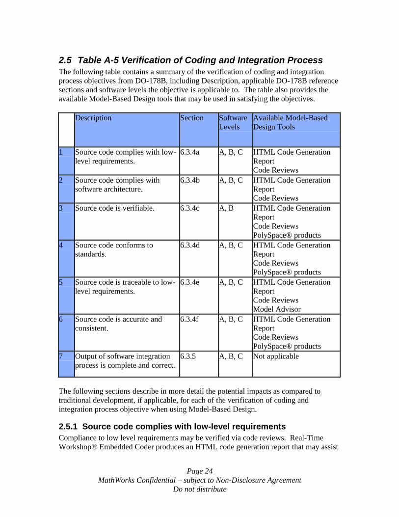
2.5 Table A-5 Verification of Coding and Integration Process
The following table contains a summary of the verification of coding and integration
process objectives from DO-178B, including Description, applicable DO-178B reference
sections and software levels the objective is applicable to. The table also provides the
available Model-Based Design tools that may be used in satisfying the objectives.
Description Section Software
Levels
Available Model-Based
Design Tools
1 Source code complies with low-
level requirements.
6.3.4a A, B, C HTML Code Generation
Report
Code Reviews
2 Source code complies with
software architecture.
6.3.4b A, B, C HTML Code Generation
Report
Code Reviews
3 Source code is verifiable. 6.3.4c A, B HTML Code Generation
Report
Code Reviews
PolySpace® products
4 Source code conforms to
standards.
6.3.4d A, B, C HTML Code Generation
Report
Code Reviews
PolySpace® products
5 Source code is traceable to low-
level requirements.
6.3.4e A, B, C HTML Code Generation
Report
Code Reviews
Model Advisor
6 Source code is accurate and
consistent.
6.3.4f A, B, C HTML Code Generation
Report
Code Reviews
PolySpace® products
7 Output of software integration
process is complete and correct.
6.3.5 A, B, C Not applicable
The following sections describe in more detail the potential impacts as compared to
traditional development, if applicable, for each of the verification of coding and
integration process objective when using Model-Based Design.
2.5.1 Source code complies with low-level requirements
Compliance to low level requirements may be verified via code reviews. Real-Time
Workshop® Embedded Coder produces an HTML code generation report that may assist
Page 25
MathWorks Confidential – subject to Non-Disclosure Agreement
Do not distribute
in code reviews by providing traceability from the code to the models, including
hyperlinks to the components in the models.
2.5.2 Source code complies with software architecture
Compliance to software architecture may be verified via code reviews. Real-Time
Workshop® Embedded Coder produces an HTML code generation report that may assist
in code reviews by providing traceability from the code to the models, including
hyperlinks to the components in the models.
2.5.3 Source code is verifiable
Verifiability of the code may be verified via code reviews. Real-Time Workshop®
Embedded Coder produces an HTML code generation report that may assist in code
reviews by providing traceability from the code to the models, including hyperlinks to the
components in the models. The PolySpace® products can assist in the identification of
unreachable and therefore non-verifiable code. The PolySpace® products have an
integration with Simulink.
2.5.4 Source code conforms to standards
Standards compliance may be verified using the PolySpace® products MISRA-C checker.
This MISRA-C checker has an integration with Simulink.
2.5.5 Source code is traceable to low-level requirements
Traceability may be verified via code reviews. Real-Time Workshop® Embedded Coder
produces an HTML code generation report that may assist in code reviews by providing
traceability from the code to the models, including hyperlinks to the components in the
models. The Model Advisor may be used to assist in verifying the commenting settings
used by Real-Time Workshop® Embedded Coder are appropriate for tracing the source
code to the models.
2.5.6 Source code is accurate and consistent
Accuracy and consistency may be verified via code reviews. Real-Time Workshop®
Embedded Coder produces an HTML code generation report that may assist in code
reviews by providing traceability from the code to the models, including hyperlinks to the
components in the models.
The PolySpace® products have the capability to identify run-time errors such as potential
underflow, overflow, divide by zero, etc.
2.5.7 Output of software integration process is complete and correct
Because the integration process is outside of the scope of Model-Based Design, this may
be verified using traditional methods.
Page 26
MathWorks Confidential – subject to Non-Disclosure Agreement
Do not distribute
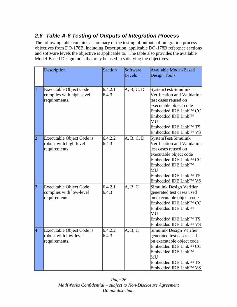
2.6 Table A-6 Testing of Outputs of Integration Process
The following table contains a summary of the testing of outputs of integration process
objectives from DO-178B, including Description, applicable DO-178B reference sections
and software levels the objective is applicable to. The table also provides the available
Model-Based Design tools that may be used in satisfying the objectives.
Description Section Software
Levels
Available Model-Based
Design Tools
1 Executable Object Code
complies with high-level
requirements.
6.4.2.1
6.4.3
A, B, C, D SystemTest/Simulink
Verification and Validation
test cases reused on
executable object code
Embedded IDE Link™ CC
Embedded IDE Link™
MU
Embedded IDE Link™ TS
Embedded IDE Link™ VS
2 Executable Object Code is
robust with high-level
requirements.
6.4.2.2
6.4.3
A, B, C, D SystemTest/Simulink
Verification and Validation
test cases reused on
executable object code
Embedded IDE Link™ CC
Embedded IDE Link™
MU
Embedded IDE Link™ TS
Embedded IDE Link™ VS
3 Executable Object Code
complies with low-level
requirements.
6.4.2.1
6.4.3
A, B, C Simulink Design Verifier
generated test cases used
on executable object code
Embedded IDE Link™ CC
Embedded IDE Link™
MU
Embedded IDE Link™ TS
Embedded IDE Link™ VS
4 Executable Object Code is
robust with low-level
requirements.
6.4.2.2
6.4.3
A, B, C Simulink Design Verifier
generated test cases used
on executable object code
Embedded IDE Link™ CC
Embedded IDE Link™
MU
Embedded IDE Link™ TS
Embedded IDE Link™ VS
Page 27
MathWorks Confidential – subject to Non-Disclosure Agreement
Do not distribute
Description Section Software
Levels
Available Model-Based
Design Tools
5 Executable Object Code is
compatible with target
computer.
6.4.3a A, B, C, D Embedded IDE Link™ CC
Embedded IDE Link™
MU
Embedded IDE Link™ TS
Embedded IDE Link™ VS
The following sections describe in more detail the potential impacts as compared to
traditional development, if applicable, for each testing of outputs of integration process
objective when using Model-Based Design.
2.6.1 Executable Object Code complies with high-level requirements
The executable object code may be verified by re-using the same test cases that are used
to verify the models. During execution of the model verification tests, using SystemTest
and Simulink Verification and Validation, the inputs and outputs of each model under test
can be logged and saved for use in verifying the executable object code.
The executable object code may be tested on a target processor or DSP using Embedded
IDE Link™ CC, Embedded IDE Link™ MU, Embedded IDE Link™ TS, or Embedded
IDE Link™ VS.
2.6.2 Executable Object Code is robust with high-level requirements
Robustness tests should be developed against the models and may be done using
SystemTest and Simulink Verification and Validation. The robustness of the executable
object code may then be verified by re-using the same test cases that are used to verify
robustness of the models. During execution of the model verification tests, using
SystemTest and Simulink Verification and Validation, the inputs and outputs of each
model under test can be logged and saved for use in verifying the executable object code.
The executable object code may be tested on a target processor or DSP using Embedded
IDE Link™ CC, Embedded IDE Link™ MU, Embedded IDE Link™ TS, or Embedded
IDE Link™ VS.
2.6.3 Executable Object Code complies with low-level requirements
Simulink Design Verifier may be used to generate low level tests from the model. These
test cases can then be run on the model and the executable object code, and the results
compared to demonstrate that the executable object code complies with the low level
requirements.
Page 28
MathWorks Confidential – subject to Non-Disclosure Agreement
Do not distribute
The executable object code may be tested on a target processor or DSP using Embedded
IDE Link™ CC, Embedded IDE Link™ MU, Embedded IDE Link™ TS, or Embedded
IDE Link™ VS.
Alternatively, verification against the low level requirements may be eliminated, if it can
be shown that requirements based coverage and structural coverage are achieved using
the high level requirements based tests (i.e. software integration tests). The following
guidance is provided in section 6.4 of DO-178B:
If a test case and its corresponding test procedure are developed and executed for
hardware/software integration testing or software integration testing and satisfy
the requirements-based coverage and structural coverage, it is not necessary to
duplicate the test for low-level testing. Substituting nominally equivalent low-
level tests for high-level tests may be less effective due to the reduced amount of
overall functionality tested.
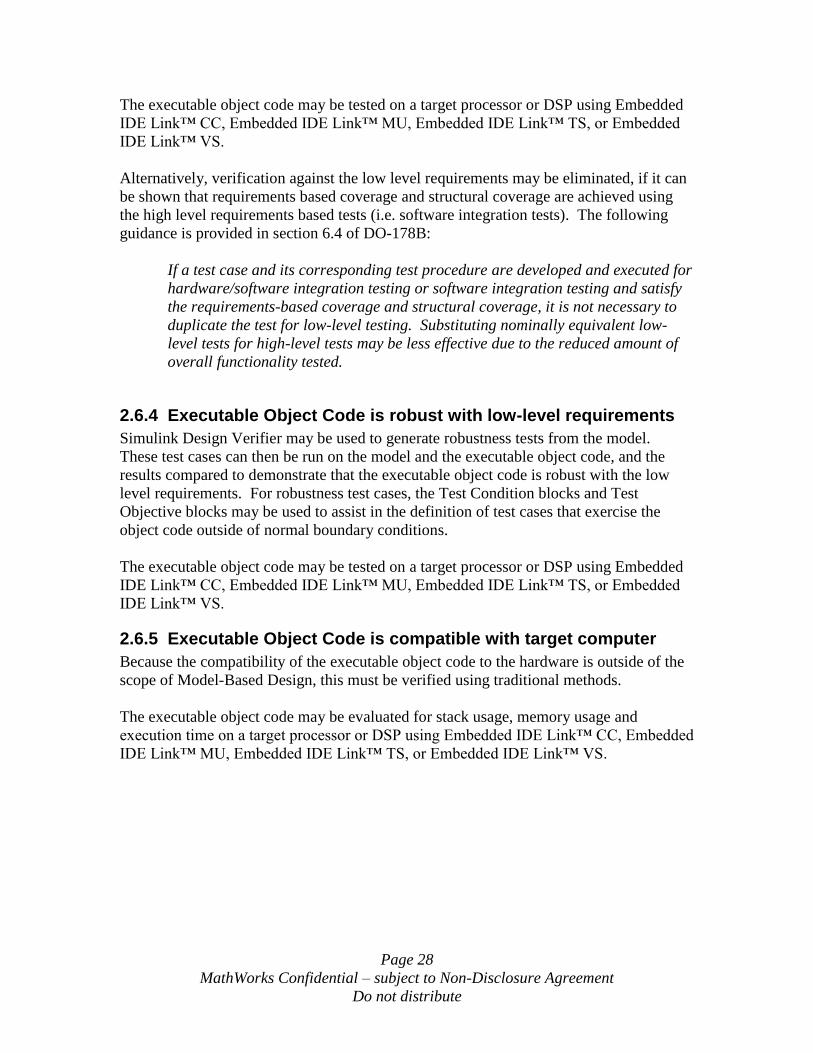
2.6.4 Executable Object Code is robust with low-level requirements
Simulink Design Verifier may be used to generate robustness tests from the model.
These test cases can then be run on the model and the executable object code, and the
results compared to demonstrate that the executable object code is robust with the low
level requirements. For robustness test cases, the Test Condition blocks and Test
Objective blocks may be used to assist in the definition of test cases that exercise the
object code outside of normal boundary conditions.
The executable object code may be tested on a target processor or DSP using Embedded
IDE Link™ CC, Embedded IDE Link™ MU, Embedded IDE Link™ TS, or Embedded
IDE Link™ VS.
2.6.5 Executable Object Code is compatible with target computer
Because the compatibility of the executable object code to the hardware is outside of the
scope of Model-Based Design, this must be verified using traditional methods.
The executable object code may be evaluated for stack usage, memory usage and
execution time on a target processor or DSP using Embedded IDE Link™ CC, Embedded
IDE Link™ MU, Embedded IDE Link™ TS, or Embedded IDE Link™ VS.
Page 29
MathWorks Confidential – subject to Non-Disclosure Agreement
Do not distribute
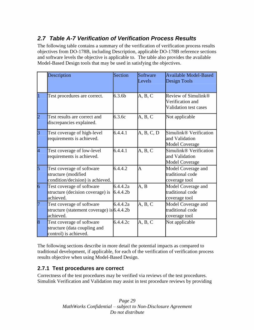
2.7 Table A-7 Verification of Verification Process Results
The following table contains a summary of the verification of verification process results
objectives from DO-178B, including Description, applicable DO-178B reference sections
and software levels the objective is applicable to. The table also provides the available
Model-Based Design tools that may be used in satisfying the objectives.
Description Section Software
Levels
Available Model-Based
Design Tools
1 Test procedures are correct. 6.3.6b A, B, C Review of Simulink®
Verification and
Validation test cases
2 Test results are correct and
discrepancies explained.
6.3.6c A, B, C Not applicable
3 Test coverage of high-level
requirements is achieved.
6.4.4.1 A, B, C, D Simulink® Verification
and Validation
Model Coverage
4 Test coverage of low-level
requirements is achieved.
6.4.4.1 A, B, C Simulink® Verification
and Validation
Model Coverage
5 Test coverage of software
structure (modified
condition/decision) is achieved.
6.4.4.2 A Model Coverage and
traditional code
coverage tool
6 Test coverage of software
structure (decision coverage) is
achieved.
6.4.4.2a
6.4.4.2b
A, B Model Coverage and
traditional code
coverage tool
7 Test coverage of software
structure (statement coverage) is
achieved.
6.4.4.2a
6.4.4.2b
A, B, C Model Coverage and
traditional code
coverage tool
8 Test coverage of software
structure (data coupling and
control) is achieved.
6.4.4.2c A, B, C Not applicable
The following sections describe in more detail the potential impacts as compared to
traditional development, if applicable, for each of the verification of verification process
results objective when using Model-Based Design.
2.7.1 Test procedures are correct
Correctness of the test procedures may be verified via reviews of the test procedures.
Simulink Verification and Validation may assist in test procedure reviews by providing
Page 30
MathWorks Confidential – subject to Non-Disclosure Agreement
Do not distribute
traceability from the test cases to the requirements, including hyperlinks to the
requirements in the higher level requirements document.
2.7.2 Test results are correct and discrepancies explained
Correctness of the test results may be verified via reviews of the test results. As an
alternative, it is possible to develop a processor in the loop test platform for the
executable object code that could be qualified as a verification tool in order to determine
pass/fail of the results.
2.7.3 Test coverage of high-level requirements is achieved
Test coverage of high level software requirements may be verified via reviews of the test
cases and traceability to the high level requirements. Simulink Verification and
Validation can be used to trace the test cases to the high level requirements, thus
providing the capability to assist in verifying that each requirement has appropriate test
cases associated with it.
2.7.4 Test coverage of low-level requirements is achieved
Test coverage of low level software requirements may be verified using the Simulink
Verification and Validation model coverage report during execution of the low level
requirements based tests. The model coverage report provides data to assist in proving
that low level requirements are fully covered during testing.
2.7.5 Test coverage of software structure (modified condition/decision) is achieved
Modified condition/decision coverage of the software structure may be verified via a
commercial off the shelf structural coverage analysis tool. This analysis will be
accomplished during the execution of the requirements based tests described in 2.6.1.
If requirements based test cases are developed at the model level and reused for testing of
the executable object code, then the Model Coverage Tool may be used during
development of the requirements based test cases to help predict the effectiveness of
those test cases in providing structural coverage for the generated code.
2.7.6 Test coverage of software structure (decision coverage) is achieved
Decision coverage of the software structure may be verified via a commercial off the
shelf structural coverage analysis tool. This analysis will be accomplished during the
execution of the requirements based tests described in 2.6.1.
If requirements based test cases are developed at the model level and reused for testing of
the executable object code, then the Model Coverage Tool may be used during
development of the requirements based test cases to help predict the effectiveness of
those test cases in providing structural coverage for the generated code.
Page 31
MathWorks Confidential – subject to Non-Disclosure Agreement
Do not distribute
2.7.7 Test coverage of software structure (statement coverage) is achieved
Statement coverage of the software structure may be verified via a commercial off the
shelf structural coverage analysis tool. This analysis will be accomplished during the
execution of the requirements based tests described in 2.6.1.
If requirements based test cases are developed at the model level and reused for testing of
the executable object code, then the Model Coverage Tool may be used during
development of the requirements based test cases to help predict the effectiveness of
those test cases in providing structural coverage for the generated code.
2.7.8 Test coverage of software structure (data coupling and control) is achieved
Because the data coupling and control is outside of the scope of code generated from
Model-Based Design, this may be verified using traditional methods. The test coverage
for data coupling and control would involve verification of the data interfaces to and from
the automatically generated code and also the calling sequence of the automatically
generated code in relation to other code modules.
Page 32
MathWorks Confidential – subject to Non-Disclosure Agreement
Do not distribute
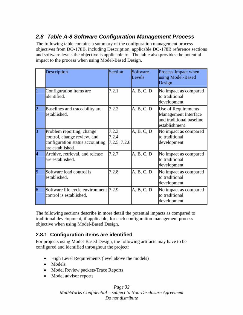
2.8 Table A-8 Software Configuration Management Process
The following table contains a summary of the configuration management process
objectives from DO-178B, including Description, applicable DO-178B reference sections
and software levels the objective is applicable to. The table also provides the potential
impact to the process when using Model-Based Design.
Description Section Software
Levels
Process Impact when
using Model-Based
Design
1 Configuration items are
identified.
7.2.1 A, B, C, D No impact as compared
to traditional
development
2 Baselines and traceability are
established.
7.2.2 A, B, C, D Use of Requirements
Management Interface
and traditional baseline
establishment
3 Problem reporting, change
control, change review, and
configuration status accounting
are established.
7.2.3,
7.2.4,
7.2.5, 7.2.6
A, B, C, D No impact as compared
to traditional
development
4 Archive, retrieval, and release
are established.
7.2.7 A, B, C, D No impact as compared
to traditional
development
5 Software load control is
established.
7.2.8 A, B, C, D No impact as compared
to traditional
development
6 Software life cycle environment
control is established.
7.2.9 A, B, C, D No impact as compared
to traditional
development
The following sections describe in more detail the potential impacts as compared to
traditional development, if applicable, for each configuration management process
objective when using Model-Based Design.
2.8.1 Configuration items are identified
For projects using Model-Based Design, the following artifacts may have to be
configured and identified throughout the project:
High Level Requirements (level above the models)
Models
Model Review packets/Trace Reports
Model advisor reports
Page 33
MathWorks Confidential – subject to Non-Disclosure Agreement
Do not distribute
Automatically Generated code
Model Test harnesses
Model Test scripts
SystemTest files
Model Test results reports
Model coverage reports
Object code structural coverage reports
These are in addition to or in substitute of traditional configured items.
2.8.2 Baselines and traceability are established
This is the same as for traditional projects. Part of the traceability may be covered by the
Requirements Management Interface.
2.8.3 Problem reporting, change control, change review, and configuration status accounting are established
This is the same as for traditional projects.
2.8.4 Archive, retrieval, and release are established
This is the same as for traditional projects. The version of the Model-Based Design tools
used on the project may have to be archived.
2.8.5 Software load control is established
This is the same as for traditional projects.
2.8.6 Software life cycle environment control is established
This is the same as for traditional projects.
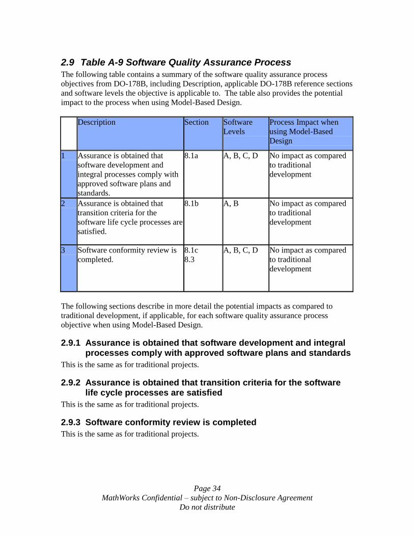
Page 34
MathWorks Confidential – subject to Non-Disclosure Agreement
Do not distribute
2.9 Table A-9 Software Quality Assurance Process
The following table contains a summary of the software quality assurance process
objectives from DO-178B, including Description, applicable DO-178B reference sections
and software levels the objective is applicable to. The table also provides the potential
impact to the process when using Model-Based Design.
Description Section Software
Levels
Process Impact when
using Model-Based
Design
1 Assurance is obtained that
software development and
integral processes comply with
approved software plans and
standards.
8.1a A, B, C, D No impact as compared
to traditional
development
2 Assurance is obtained that
transition criteria for the
software life cycle processes are
satisfied.
8.1b A, B No impact as compared
to traditional
development
3 Software conformity review is
completed.
8.1c
8.3
A, B, C, D No impact as compared
to traditional
development
The following sections describe in more detail the potential impacts as compared to
traditional development, if applicable, for each software quality assurance process
objective when using Model-Based Design.
2.9.1 Assurance is obtained that software development and integral processes comply with approved software plans and standards
This is the same as for traditional projects.
2.9.2 Assurance is obtained that transition criteria for the software life cycle processes are satisfied
This is the same as for traditional projects.
2.9.3 Software conformity review is completed
This is the same as for traditional projects.

Page 35
MathWorks Confidential – subject to Non-Disclosure Agreement
Do not distribute
2.10 Table A-10 Certification Liaison Process
The following table contains a summary of the certification liaison process objectives
from DO-178B, including Description, applicable DO-178B reference sections and
software levels the objective is applicable to. The table also provides the potential impact
to the process when using Model-Based Design.
Description Section Software
Levels
Process Impact when
using Model-Based
Design
1 Communication and
understanding between the
applicant and the certification
authority is established.
9.0 A, B, C, D No impact as compared
to traditional
development
2 The means of compliance is
proposed and agreement with the
Plan for Software Aspects of
Certification is obtained.
9.1 A, B, C, D No impact as compared
to traditional
development
3 Compliance substantiation is
provided.
9.2 A, B, C, D No impact as compared
to traditional
development
The following sections describe in more detail the potential impacts as compared to
traditional development, if applicable, for each certification liaison process objective
when using Model-Based Design.
2.10.1 Communication and understanding between the applicant and the certification authority is established
This is the same as for traditional projects.
2.10.2 The means of compliance is proposed and agreement with the Plan for Software Aspects of Certification is obtained
This is the same as for traditional projects.
2.10.3 Compliance substantiation is provided
This is the same as for traditional projects.
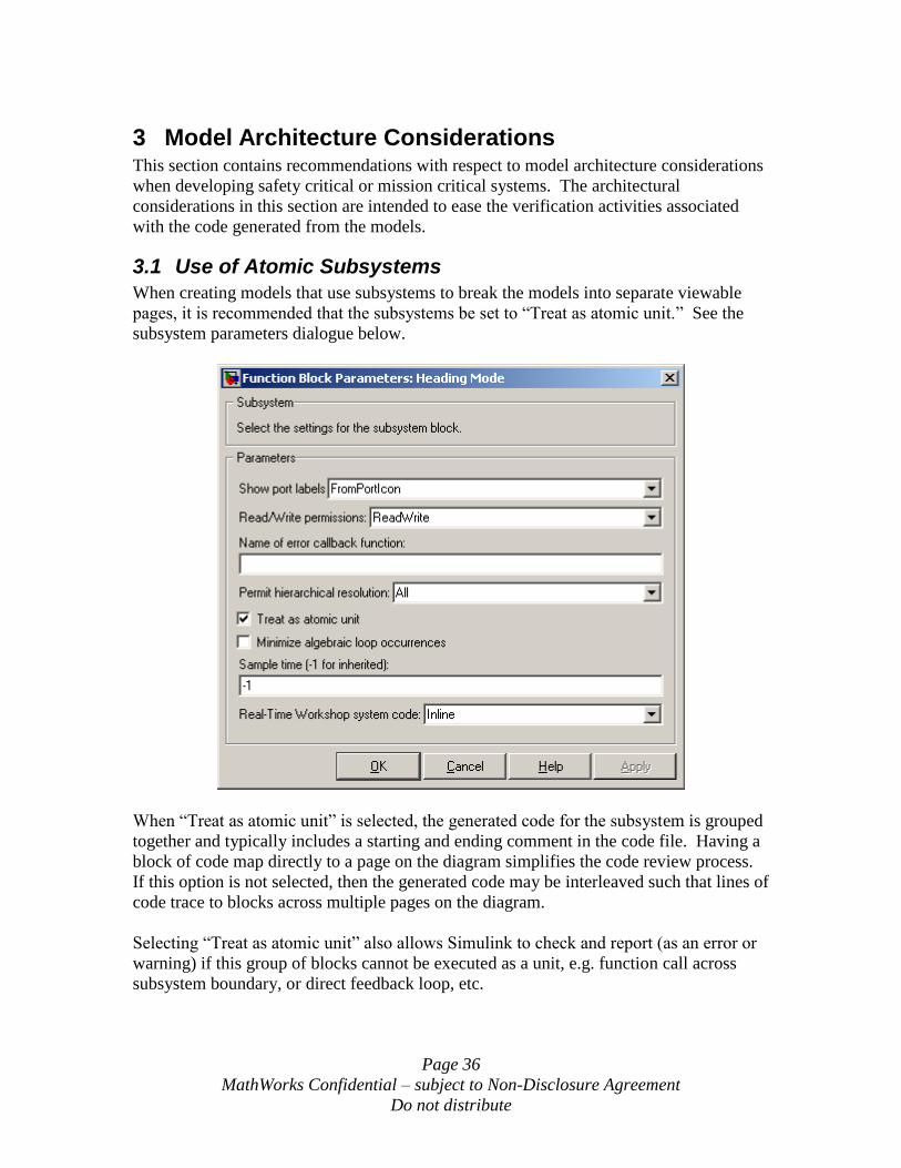
Page 36
MathWorks Confidential – subject to Non-Disclosure Agreement
Do not distribute
3 Model Architecture Considerations This section contains recommendations with respect to model architecture considerations
when developing safety critical or mission critical systems. The architectural
considerations in this section are intended to ease the verification activities associated
with the code generated from the models.
3.1 Use of Atomic Subsystems
When creating models that use subsystems to break the models into separate viewable
pages, it is recommended that the subsystems be set to “Treat as atomic unit.” See the
subsystem parameters dialogue below.
When “Treat as atomic unit” is selected, the generated code for the subsystem is grouped
together and typically includes a starting and ending comment in the code file. Having a
block of code map directly to a page on the diagram simplifies the code review process.
If this option is not selected, then the generated code may be interleaved such that lines of
code trace to blocks across multiple pages on the diagram.
Selecting “Treat as atomic unit” also allows Simulink to check and report (as an error or
warning) if this group of blocks cannot be executed as a unit, e.g. function call across
subsystem boundary, or direct feedback loop, etc.
Page 37
MathWorks Confidential – subject to Non-Disclosure Agreement
Do not distribute
“Real-Time Workshop system code” should be set as “Inline” or “Function.” Use of
“Auto” or “Reusable function” can lead to confusion with respect to requirements
traceability in the generated code. If reusable functions are desired, then Model
Reference should be used to instantiate the reusable functions.
3.2 Use of Model Reference
The model reference feature allows a large model to be broken into smaller separately
configured units. This results in separate code files for each of the separate models.
There are many advantages to having these separately configured files:
Each model and it‟s associated code can be verified as a separate component
When a reference model changes, only it‟s code has to be reviewed
When a reference model changes, only it‟s verification testing has to be
performed
Regression analysis is greatly simplified
Structural coverage analysis is simplified when using smaller models and code
Reference model code can be reused
When using Model Reference, especially with large teams, configuration management of
the reference models is very important. There are two “best practice” scenarios for
configuration management of the reference models that are described here.
Scenario 1 – Model developer checks in the simulation target and embedded
target source code with the model into the configuration management system
Under this scenario the model developer creates a simulation target that will be
used by other model developers that call the referenced model. This target is
created in the form of a .mex32 executable file and would be checked into the
software configuration management tool along with the model. The model
developer would also generate the target source code and check this in with the
model. This ensures that all time and date stamps and the model checksums
match those for the generated code and simulation targets.
For this scenario, any user of the reference model would get the latest copy of the
model, source code and simulation target from the configuration management
system before using it. The Rebuild Option would be set to Never for all
reference models.
The advantage of using this scenario is that the model, source code and simulation
target could all be verified and approved in the software configuration
management system and locked down until such time as a change is necessary.
Additionally this would insure that all users of the reference model are working
from exactly the same files from the configuration management system.

Page 38
MathWorks Confidential – subject to Non-Disclosure Agreement
Do not distribute
Scenario 2 – Model developer checks in only the model into the configuration
management system
Under this scenario, the model developer is only responsible for creation and
check-in of the model into the configuration management system. It would be the
responsibility of the user of the reference model to create a simulation target that
will be used by other model developers that call the referenced model. Another
developer would need to generate the target source code and check this in to the
software configuration management system.
For this scenario, any user of the reference model would get the latest copy of the
model target from the configuration management system before using it. The
Rebuild Option would be set to If Any Changes Detected for all reference models.
The advantage of using this scenario is that the model, source code and simulation
target could all be verified and approved in the software configuration
management system at different times in the development cycle and by different
groups. A disadvantage of this scenario is that insuring that all users of the
reference model are working from exactly the same files from the configuration
management system is much more difficult.
For either of the scenarios above, it is necessary to understand the reference model
dependencies and to determine when a change to one model may require a change to
another model or regeneration of the source code and simulation target for another model.
See the Model Reference documentation for a detailed description of this.
The use of model reference is analogous to the use of multiple code modules across a
large system. The Model Referencing Pane of the Configuration Parameters is shown
below:
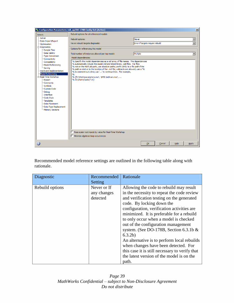
Page 39
MathWorks Confidential – subject to Non-Disclosure Agreement
Do not distribute
Recommended model reference settings are outlined in the following table along with
rationale.
Diagnostic Recommended
Setting
Rationale
Rebuild options Never or If
any changes
detected
Allowing the code to rebuild may result
in the necessity to repeat the code review
and verification testing on the generated
code. By locking down the
configuration, verification activities are
minimized. It is preferable for a rebuild
to only occur when a model is checked
out of the configuration management
system. (See DO-178B, Section 6.3.1b &
6.3.2b)
An alternative is to perform local rebuilds
when changes have been detected. For
this case it is still necessary to verify that
the latest version of the model is on the
path.
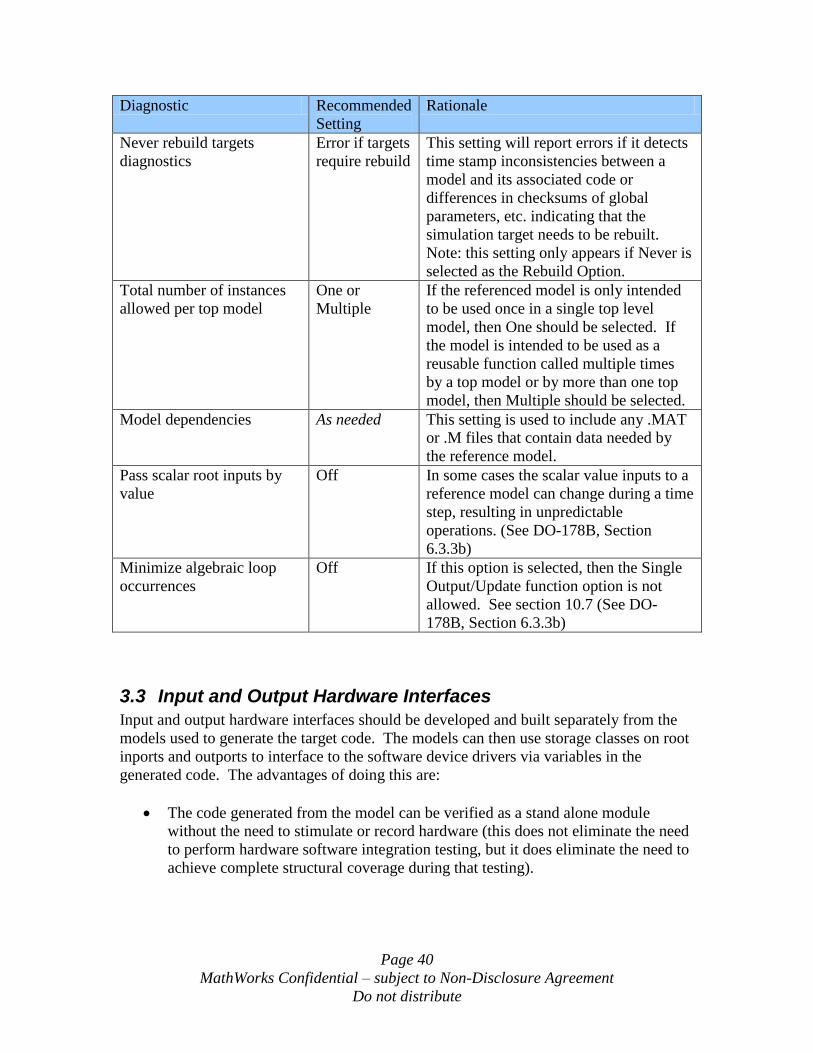
Page 40
MathWorks Confidential – subject to Non-Disclosure Agreement
Do not distribute
Diagnostic Recommended
Setting
Rationale
Never rebuild targets
diagnostics
Error if targets
require rebuild
This setting will report errors if it detects
time stamp inconsistencies between a
model and its associated code or
differences in checksums of global
parameters, etc. indicating that the
simulation target needs to be rebuilt.
Note: this setting only appears if Never is
selected as the Rebuild Option.
Total number of instances
allowed per top model
One or
Multiple
If the referenced model is only intended
to be used once in a single top level
model, then One should be selected. If
the model is intended to be used as a
reusable function called multiple times
by a top model or by more than one top
model, then Multiple should be selected.
Model dependencies As needed This setting is used to include any .MAT
or .M files that contain data needed by
the reference model.
Pass scalar root inputs by
value
Off In some cases the scalar value inputs to a
reference model can change during a time
step, resulting in unpredictable
operations. (See DO-178B, Section
6.3.3b)
Minimize algebraic loop
occurrences
Off If this option is selected, then the Single
Output/Update function option is not
allowed. See section 10.7 (See DO-
178B, Section 6.3.3b)
3.3 Input and Output Hardware Interfaces
Input and output hardware interfaces should be developed and built separately from the
models used to generate the target code. The models can then use storage classes on root
inports and outports to interface to the software device drivers via variables in the
generated code. The advantages of doing this are:
The code generated from the model can be verified as a stand alone module
without the need to stimulate or record hardware (this does not eliminate the need
to perform hardware software integration testing, but it does eliminate the need to
achieve complete structural coverage during that testing).
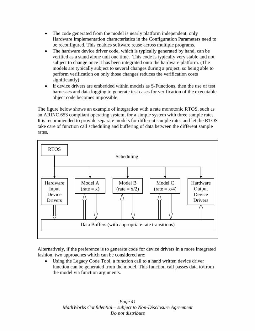
Page 41
MathWorks Confidential – subject to Non-Disclosure Agreement
Do not distribute
The code generated from the model is nearly platform independent, only
Hardware Implementation characteristics in the Configuration Parameters need to
be reconfigured. This enables software reuse across multiple programs.
The hardware device driver code, which is typically generated by hand, can be
verified as a stand alone unit one time. This code is typically very stable and not
subject to change once it has been integrated onto the hardware platform. (The
models are typically subject to several changes during a project, so being able to
perform verification on only those changes reduces the verification costs
significantly)
If device drivers are embedded within models as S-Functions, then the use of test
harnesses and data logging to generate test cases for verification of the executable
object code becomes impossible.
The figure below shows an example of integration with a rate monotonic RTOS, such as
an ARINC 653 compliant operating system, for a simple system with three sample rates.
It is recommended to provide separate models for different sample rates and let the RTOS
take care of function call scheduling and buffering of data between the different sample
rates.
Alternatively, if the preference is to generate code for device drivers in a more integrated
fashion, two approaches which can be considered are:
Using the Legacy Code Tool, a function call to a hand written device driver
function can be generated from the model. This function call passes data to/from
the model via function arguments.
RTOS
Hardware
Input
Device
Drivers
Hardware
Output
Device
Drivers
Model A
(rate = x)
Model B
(rate = x/2)
Model C
(rate = x/4)
Data Buffers (with appropriate rate transitions)
Scheduling
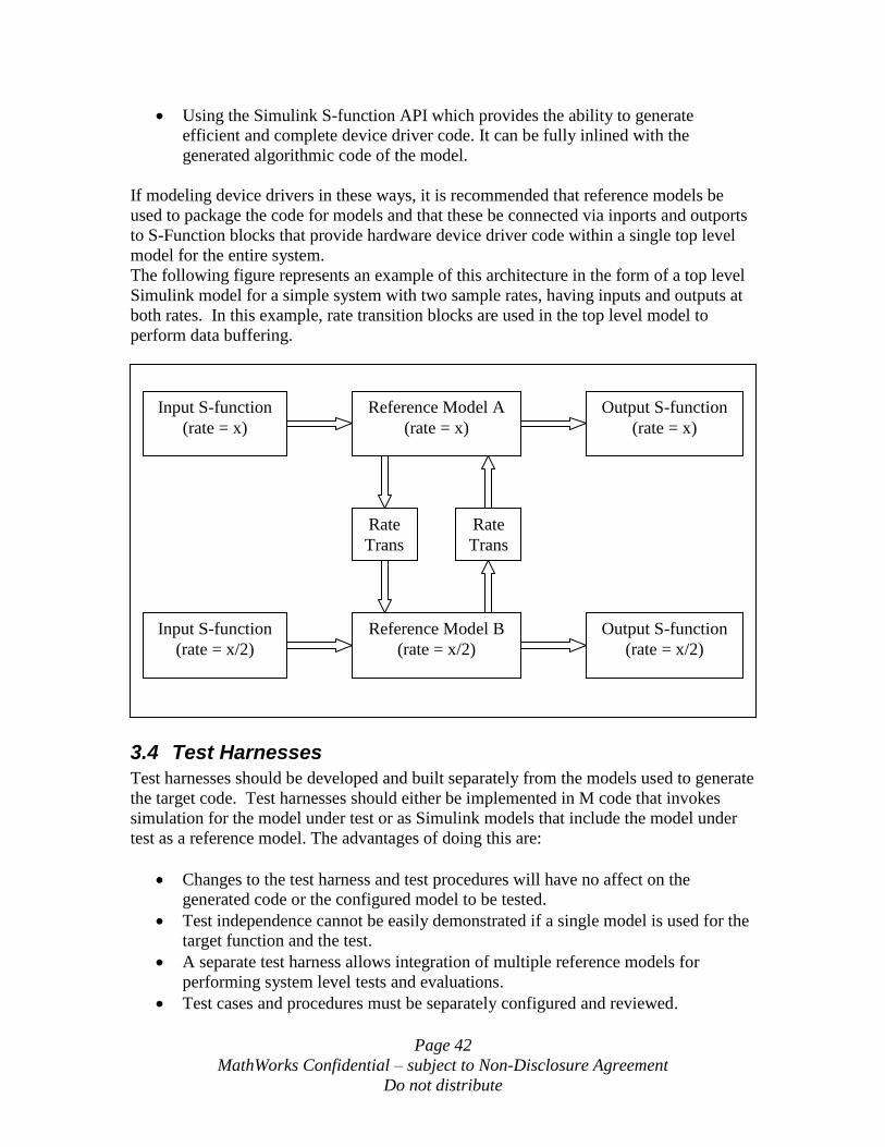
Page 42
MathWorks Confidential – subject to Non-Disclosure Agreement
Do not distribute
Using the Simulink S-function API which provides the ability to generate
efficient and complete device driver code. It can be fully inlined with the
generated algorithmic code of the model.
If modeling device drivers in these ways, it is recommended that reference models be
used to package the code for models and that these be connected via inports and outports
to S-Function blocks that provide hardware device driver code within a single top level
model for the entire system.
The following figure represents an example of this architecture in the form of a top level
Simulink model for a simple system with two sample rates, having inputs and outputs at
both rates. In this example, rate transition blocks are used in the top level model to
perform data buffering.
3.4 Test Harnesses
Test harnesses should be developed and built separately from the models used to generate
the target code. Test harnesses should either be implemented in M code that invokes
simulation for the model under test or as Simulink models that include the model under
test as a reference model. The advantages of doing this are:
Changes to the test harness and test procedures will have no affect on the
generated code or the configured model to be tested.
Test independence cannot be easily demonstrated if a single model is used for the
target function and the test.
A separate test harness allows integration of multiple reference models for
performing system level tests and evaluations.
Test cases and procedures must be separately configured and reviewed.
Input S-function
(rate = x)
Reference Model A
(rate = x)
Output S-function
(rate = x)
Rate
Trans
Rate
Trans
Input S-function
(rate = x/2)
Reference Model B
(rate = x/2)
Output S-function
(rate = x/2)

Page 43
MathWorks Confidential – subject to Non-Disclosure Agreement
Do not distribute
Functional models and test harness can be developed in parallel with
independence.
Data can be logged at the inputs and outputs to the model under test from the test
harness so that these test cases can be reused to verify the executable object code.
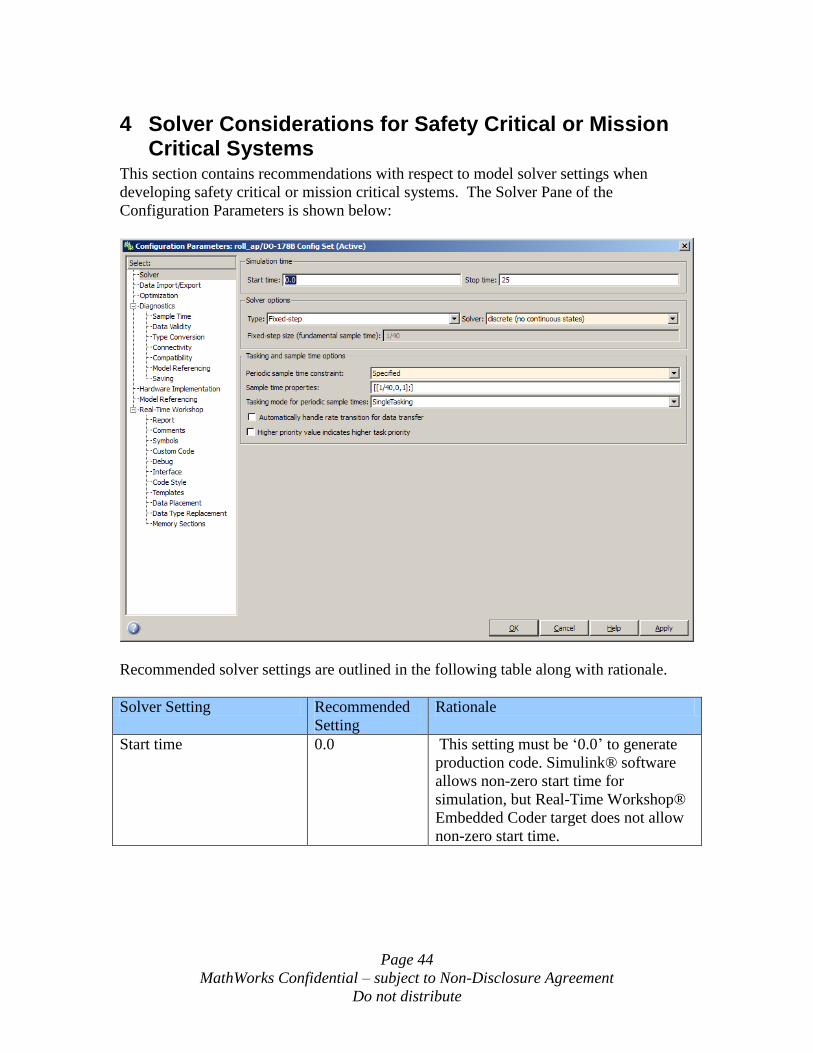
Page 44
MathWorks Confidential – subject to Non-Disclosure Agreement
Do not distribute
4 Solver Considerations for Safety Critical or Mission Critical Systems
This section contains recommendations with respect to model solver settings when
developing safety critical or mission critical systems. The Solver Pane of the
Configuration Parameters is shown below:
Recommended solver settings are outlined in the following table along with rationale.
Solver Setting Recommended
Setting
Rationale
Start time 0.0 This setting must be „0.0‟ to generate
production code. Simulink® software
allows non-zero start time for
simulation, but Real-Time Workshop®
Embedded Coder target does not allow
non-zero start time.
Page 45
MathWorks Confidential – subject to Non-Disclosure Agreement
Do not distribute
Solver Setting Recommended
Setting
Rationale
Stop time Any positive
value
The time in seconds of this setting must
be shorter than „Application lifespan
(days)‟ on Optimization pane. By
default, „Application lifespan (days)‟ is
inf. Any positive value is valid and this
setting has no effect on generated code.
Type Fixed-step Fixed-step solver is required for
embedded code generation.
Solver Discrete (no
continuous
states)
Discrete is required for production code.
Fixed step size
(fundamental sample time)
Any positive
value
This setting is enabled only if
„Unconstrained‟ is selected for the
periodic sample time constraint. The
value should not be set as „Auto‟.
Periodic sample time
constraint
Specified,
Ensure sample
time
independent or
Unconstrained
For most models the sample time should
be „Specified‟ or „Unconstrained‟ in
order to define the rate that the
generated code is to run at. The
exception to this is for reference
models, for those that are intended to be
reusable functions that inherit their
sample time from the calling model
„Ensure sample time independent‟
should be selected, and for those that
have a fixed sample time
„Unconstrained‟ should be specified.
Sample time properties [[Period, offset,
priority], ….]
This setting is appears only if
„Specified‟ is selected for the periodic
sample time constraint. Specify the
period, offset and priority of each
sample time in the model. Faster sample
times must have higher priority than
slower sample times. See the solver
Help documentation for how to set up
the sample time period, offset and
priority.
Page 46
MathWorks Confidential – subject to Non-Disclosure Agreement
Do not distribute
Solver Setting Recommended
Setting
Rationale
Tasking mode for periodic
sample times
SingleTasking
or MultiTasking
If „Ensure sample time independent‟ is
selected for a reference model, this
setting will not appear. This should be
set to „SingleTasking‟ if the model is
intended to run at a single rate or the
model is intended to run at multiple
rates in one task. Otherwise it should
be set to „MultiTasking‟ if the model is
intended to run at multiple rates.
Higher priority value
indicates higher task
priority
On or Off If „Ensure sample time independent‟ is
selected for a reference model, this
setting will not appear. This option
determines whether the priority for
Sample time properties uses the lowest
values as highest priority or the highest
values as highest priority.
Automatically handle data
transfers between tasks
Off If „Ensure sample time independent‟ is
selected for a reference model, this
setting will not appear. Setting this to
On could result in rate transition code
being inserted without a model
requirement to trace to. This violates
traceability requirements. (See DO-
178B, Section 6.3.4e)
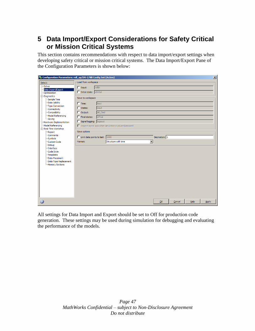
Page 47
MathWorks Confidential – subject to Non-Disclosure Agreement
Do not distribute
5 Data Import/Export Considerations for Safety Critical or Mission Critical Systems
This section contains recommendations with respect to data import/export settings when
developing safety critical or mission critical systems. The Data Import/Export Pane of
the Configuration Parameters is shown below:
All settings for Data Import and Export should be set to Off for production code
generation. These settings may be used during simulation for debugging and evaluating
the performance of the models.
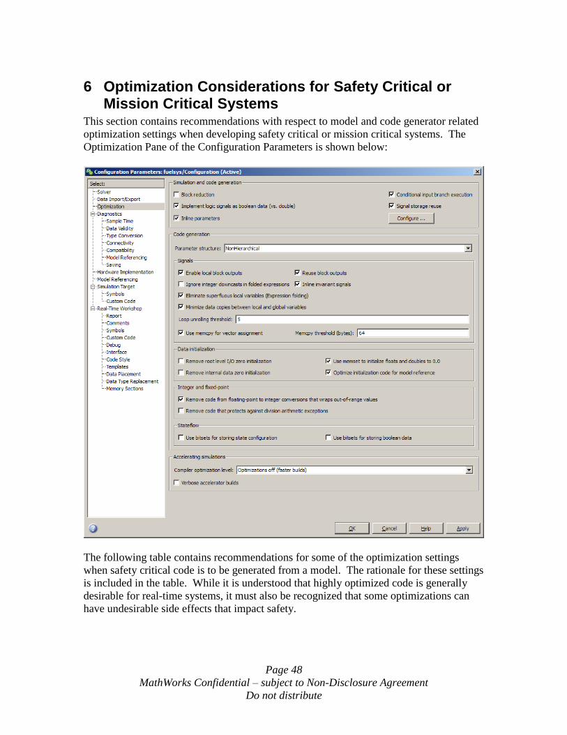
Page 48
MathWorks Confidential – subject to Non-Disclosure Agreement
Do not distribute
6 Optimization Considerations for Safety Critical or Mission Critical Systems
This section contains recommendations with respect to model and code generator related
optimization settings when developing safety critical or mission critical systems. The
Optimization Pane of the Configuration Parameters is shown below:
The following table contains recommendations for some of the optimization settings
when safety critical code is to be generated from a model. The rationale for these settings
is included in the table. While it is understood that highly optimized code is generally
desirable for real-time systems, it must also be recognized that some optimizations can
have undesirable side effects that impact safety.
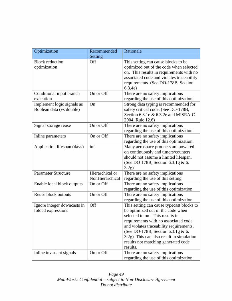
Page 49
MathWorks Confidential – subject to Non-Disclosure Agreement
Do not distribute
Optimization Recommended
Setting
Rationale
Block reduction
optimization
Off This setting can cause blocks to be
optimized out of the code when selected
on. This results in requirements with no
associated code and violates traceability
requirements. (See DO-178B, Section
6.3.4e)
Conditional input branch
execution
On or Off There are no safety implications
regarding the use of this optimization.
Implement logic signals as
Boolean data (vs double)
On Strong data typing is recommended for
safety critical code. (See DO-178B,
Section 6.3.1e & 6.3.2e and MISRA-C
2004, Rule 12.6)
Signal storage reuse On or Off There are no safety implications
regarding the use of this optimization.
Inline parameters On or Off There are no safety implications
regarding the use of this optimization.
Application lifespan (days) inf Many aerospace products are powered
on continuously and timers/counters
should not assume a limited lifespan.
(See DO-178B, Section 6.3.1g & 6.
3.2g)
Parameter Structure Hierarchical or
NonHierarchical
There are no safety implications
regarding the use of this setting.
Enable local block outputs On or Off There are no safety implications
regarding the use of this optimization.
Reuse block outputs On or Off There are no safety implications
regarding the use of this optimization.
Ignore integer downcasts in
folded expressions
Off This setting can cause typecast blocks to
be optimized out of the code when
selected to on. This results in
requirements with no associated code
and violates traceability requirements.
(See DO-178B, Section 6.3.1g & 6.
3.2g) This can also result in simulation
results not matching generated code
results.
Inline invariant signals On or Off There are no safety implications
regarding the use of this optimization.
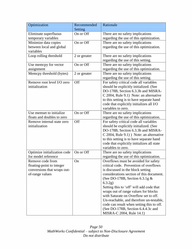
Page 50
MathWorks Confidential – subject to Non-Disclosure Agreement
Do not distribute
Optimization Recommended
Setting
Rationale
Eliminate superfluous
temporary variables
On or Off There are no safety implications
regarding the use of this optimization.
Minimize data copies
between local and global
variables
On or Off There are no safety implications
regarding the use of this optimization.
Loop rolling threshold 2 or greater There are no safety implications
regarding the use of this setting.
Use memcpy for vector
assignment
On or Off There are no safety implications
regarding the use of this optimization.
Memcpy threshold (bytes) 2 or greater There are no safety implications
regarding the use of this setting.
Remove root level I/O zero
initialization
Off For safety critical code all variables
should be explicitly initialized. (See
DO-178B, Section 6.3.3b and MISRA-
C 2004, Rule 9.1) Note: an alternative
to this setting is to have separate hand
code that explicitly initializes all I/O
variables to zero.
Use memset to initialize
floats and doubles to zero
On or Off There are no safety implications
regarding the use of this optimization.
Remove internal state zero
initialization
Off For safety critical code all variables
should be explicitly initialized. (See
DO-178B, Section 6.3.3b and MISRA-
C 2004, Rule 9.1) ) Note: an alternative
to this setting is to have separate hand
code that explicitly initializes all state
variables to zero.
Optimize initialization code
for model reference
On or Off There are no safety implications
regarding the use of this optimization.
Remove code from
floating-point to integer
conversions that wraps out-
of-range values
On Overflows must be avoided for safety
critical code. Prevention of overflows
is discussed in the block setting
considerations section of this document.
(See DO-178B, Section 6.3.1g &
6.3.2g)
Setting this to „off‟ will add code that
wraps out of range values for blocks
with Saturate on Overflow set to off.
Un-reachable, and therefore un-testable,
code can result when setting this to off.
(See DO-178B, Section 6.4.4.3c and
MISRA-C 2004, Rule 14.1)
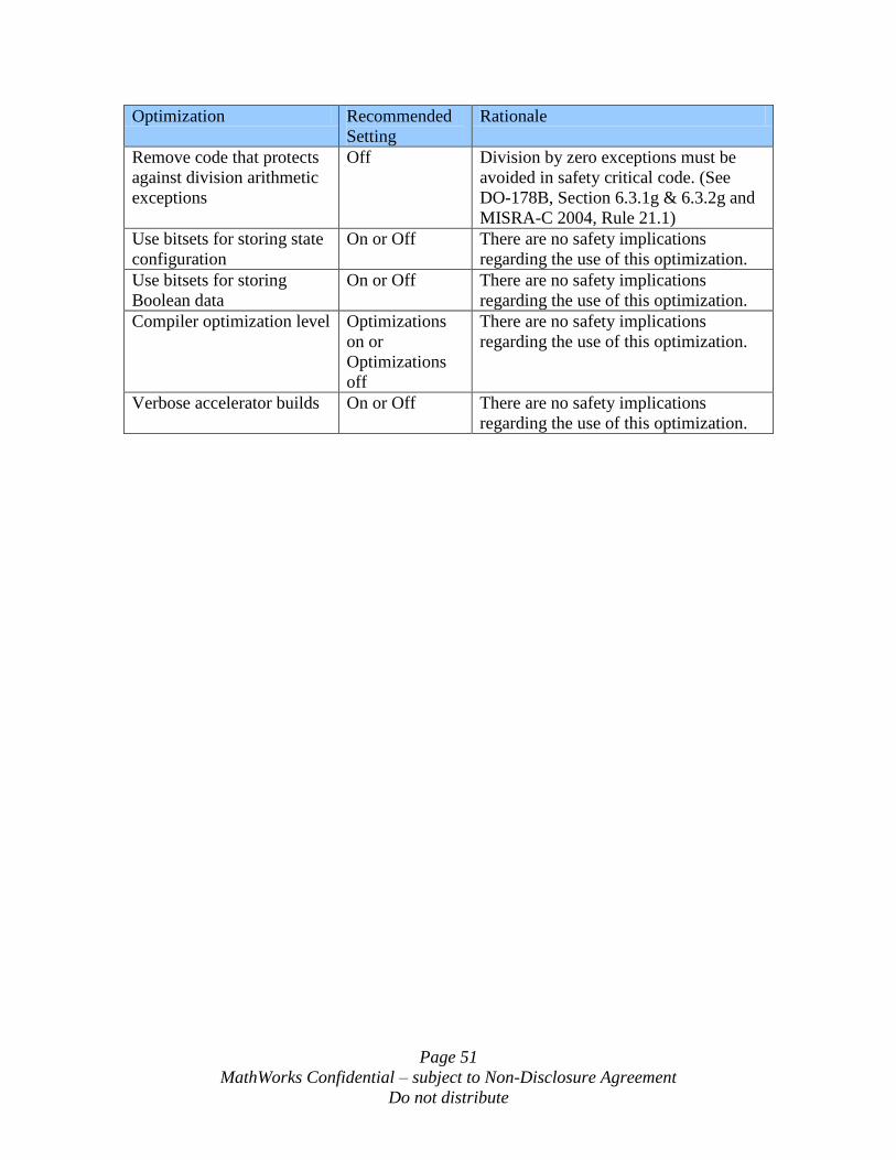
Page 51
MathWorks Confidential – subject to Non-Disclosure Agreement
Do not distribute
Optimization Recommended
Setting
Rationale
Remove code that protects
against division arithmetic
exceptions
Off Division by zero exceptions must be
avoided in safety critical code. (See
DO-178B, Section 6.3.1g & 6.3.2g and
MISRA-C 2004, Rule 21.1)
Use bitsets for storing state
configuration
On or Off There are no safety implications
regarding the use of this optimization.
Use bitsets for storing
Boolean data
On or Off There are no safety implications
regarding the use of this optimization.
Compiler optimization level Optimizations
on or
Optimizations
off
There are no safety implications
regarding the use of this optimization.
Verbose accelerator builds On or Off There are no safety implications
regarding the use of this optimization.
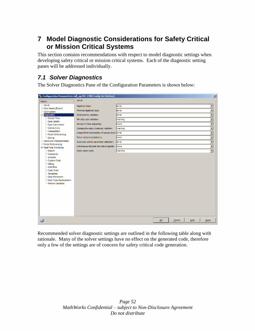
Page 52
MathWorks Confidential – subject to Non-Disclosure Agreement
Do not distribute
7 Model Diagnostic Considerations for Safety Critical or Mission Critical Systems
This section contains recommendations with respect to model diagnostic settings when
developing safety critical or mission critical systems. Each of the diagnostic setting
panes will be addressed individually.
7.1 Solver Diagnostics
The Solver Diagnostics Pane of the Configuration Parameters is shown below:
Recommended solver diagnostic settings are outlined in the following table along with
rationale. Many of the solver settings have no effect on the generated code, therefore
only a few of the settings are of concern for safety critical code generation.
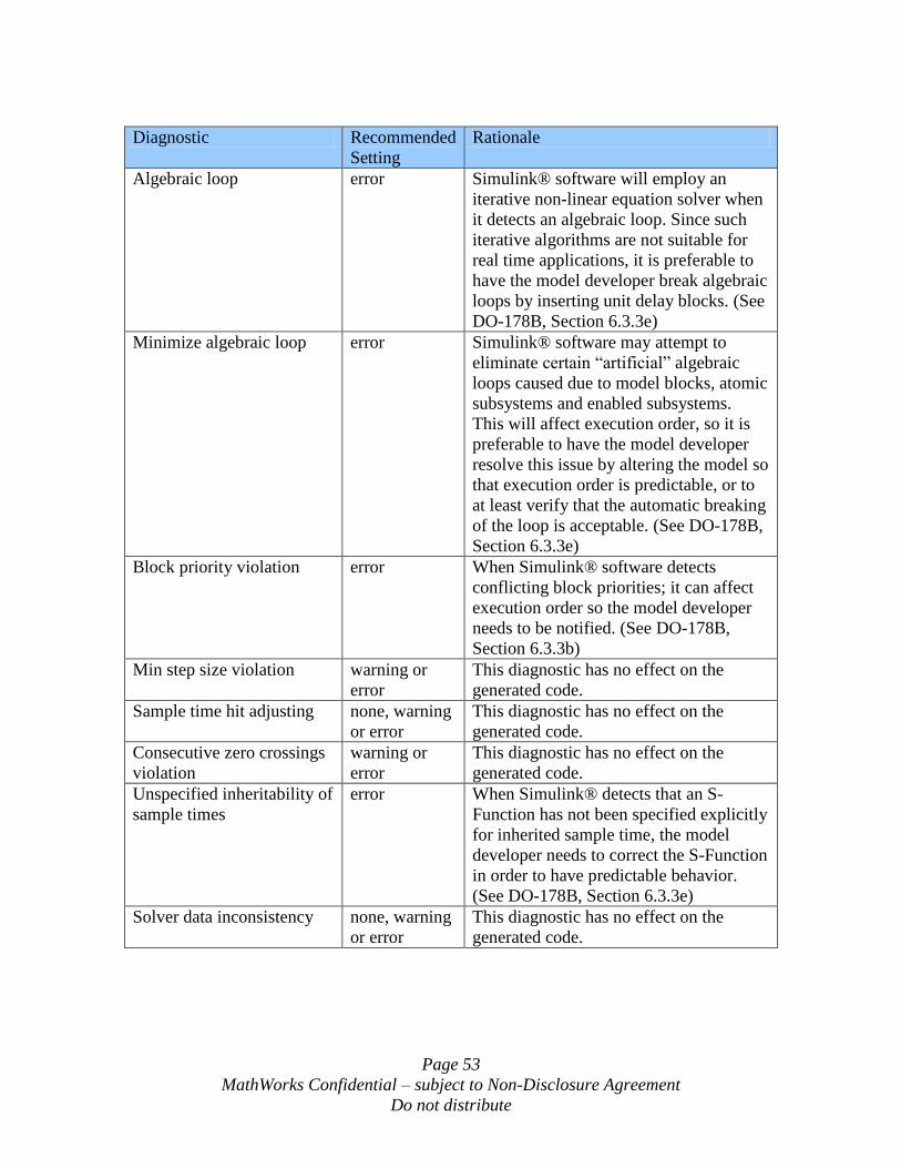
Page 53
MathWorks Confidential – subject to Non-Disclosure Agreement
Do not distribute
Diagnostic Recommended
Setting
Rationale
Algebraic loop error Simulink® software will employ an
iterative non-linear equation solver when
it detects an algebraic loop. Since such
iterative algorithms are not suitable for
real time applications, it is preferable to
have the model developer break algebraic
loops by inserting unit delay blocks. (See
DO-178B, Section 6.3.3e)
Minimize algebraic loop error Simulink® software may attempt to
eliminate certain “artificial” algebraic
loops caused due to model blocks, atomic
subsystems and enabled subsystems.
This will affect execution order, so it is
preferable to have the model developer
resolve this issue by altering the model so
that execution order is predictable, or to
at least verify that the automatic breaking
of the loop is acceptable. (See DO-178B,
Section 6.3.3e)
Block priority violation error When Simulink® software detects
conflicting block priorities; it can affect
execution order so the model developer
needs to be notified. (See DO-178B,
Section 6.3.3b)
Min step size violation warning or
error
This diagnostic has no effect on the
generated code.
Sample time hit adjusting none, warning
or error
This diagnostic has no effect on the
generated code.
Consecutive zero crossings
violation
warning or
error
This diagnostic has no effect on the
generated code.
Unspecified inheritability of
sample times
error When Simulink® detects that an S-
Function has not been specified explicitly
for inherited sample time, the model
developer needs to correct the S-Function
in order to have predictable behavior.
(See DO-178B, Section 6.3.3e)
Solver data inconsistency none, warning
or error
This diagnostic has no effect on the
generated code.
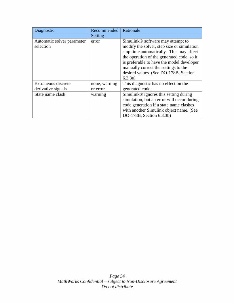
Page 54
MathWorks Confidential – subject to Non-Disclosure Agreement
Do not distribute
Diagnostic Recommended
Setting
Rationale
Automatic solver parameter
selection
error Simulink® software may attempt to
modify the solver, step size or simulation
stop time automatically. This may affect
the operation of the generated code, so it
is preferable to have the model developer
manually correct the settings to the
desired values. (See DO-178B, Section
6.3.3e)
Extraneous discrete
derivative signals
none, warning
or error
This diagnostic has no effect on the
generated code.
State name clash warning Simulink® ignores this setting during
simulation, but an error will occur during
code generation if a state name clashes
with another Simulink object name. (See
DO-178B, Section 6.3.3b)
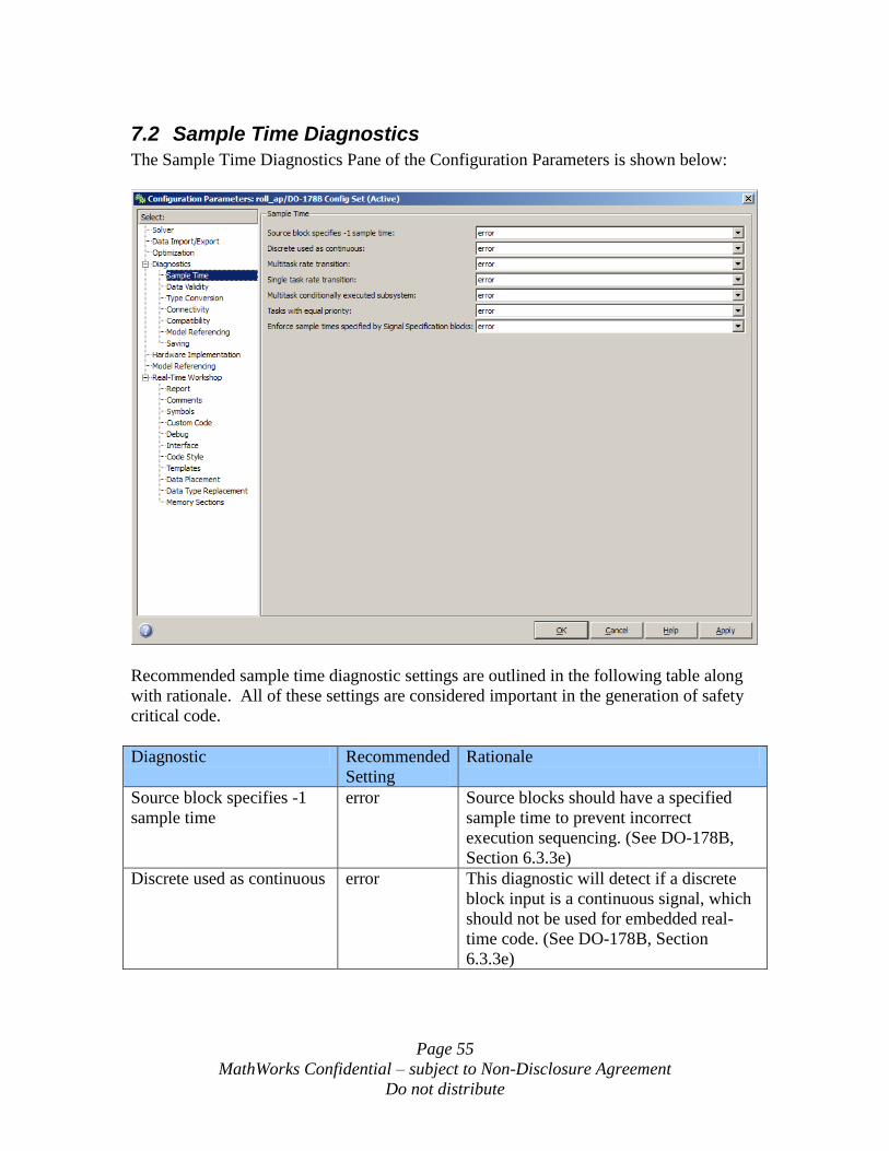
Page 55
MathWorks Confidential – subject to Non-Disclosure Agreement
Do not distribute
7.2 Sample Time Diagnostics
The Sample Time Diagnostics Pane of the Configuration Parameters is shown below:
Recommended sample time diagnostic settings are outlined in the following table along
with rationale. All of these settings are considered important in the generation of safety
critical code.
Diagnostic Recommended
Setting
Rationale
Source block specifies -1
sample time
error Source blocks should have a specified
sample time to prevent incorrect
execution sequencing. (See DO-178B,
Section 6.3.3e)
Discrete used as continuous error This diagnostic will detect if a discrete
block input is a continuous signal, which
should not be used for embedded real-
time code. (See DO-178B, Section
6.3.3e)
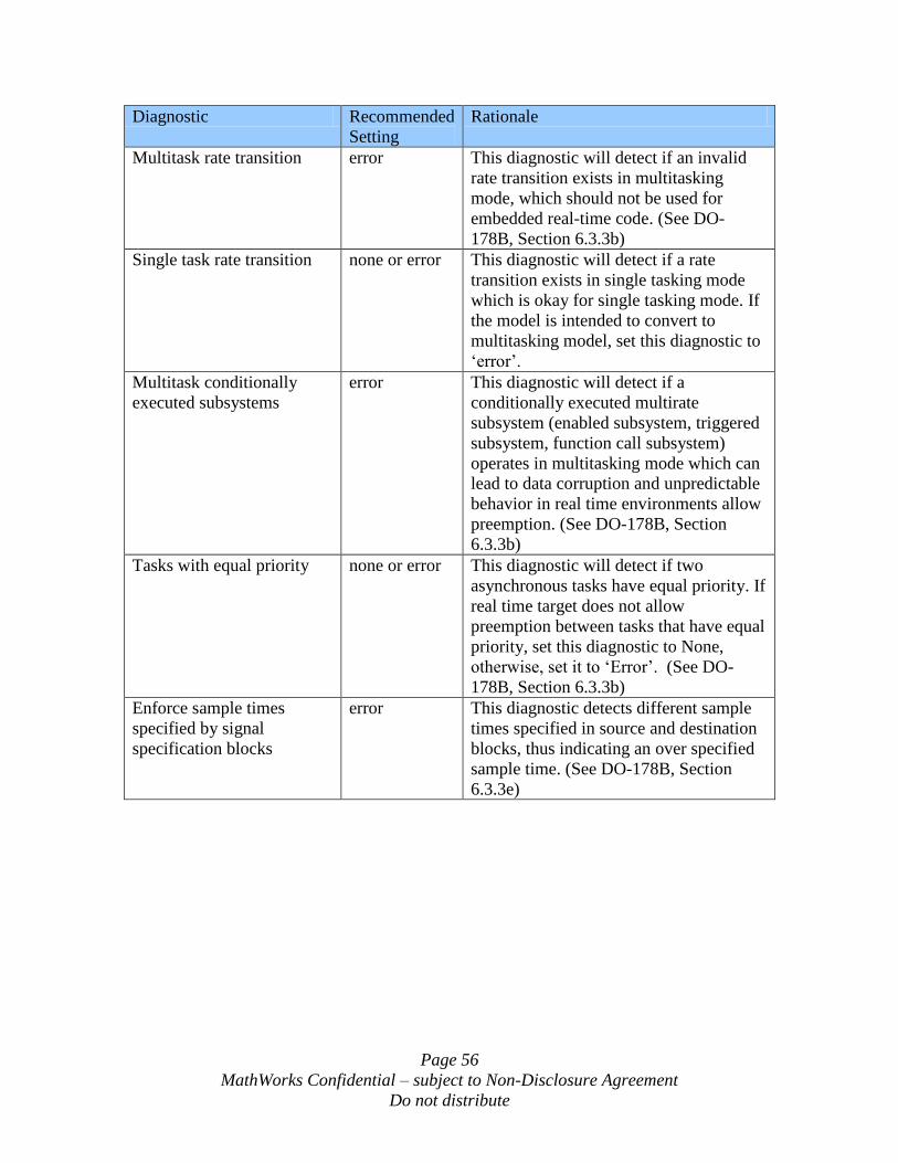
Page 56
MathWorks Confidential – subject to Non-Disclosure Agreement
Do not distribute
Diagnostic Recommended
Setting
Rationale
Multitask rate transition error This diagnostic will detect if an invalid
rate transition exists in multitasking
mode, which should not be used for
embedded real-time code. (See DO-
178B, Section 6.3.3b)
Single task rate transition none or error This diagnostic will detect if a rate
transition exists in single tasking mode
which is okay for single tasking mode. If
the model is intended to convert to
multitasking model, set this diagnostic to
„error‟.
Multitask conditionally
executed subsystems
error This diagnostic will detect if a
conditionally executed multirate
subsystem (enabled subsystem, triggered
subsystem, function call subsystem)
operates in multitasking mode which can
lead to data corruption and unpredictable
behavior in real time environments allow
preemption. (See DO-178B, Section
6.3.3b)
Tasks with equal priority none or error This diagnostic will detect if two
asynchronous tasks have equal priority. If
real time target does not allow
preemption between tasks that have equal
priority, set this diagnostic to None,
otherwise, set it to „Error‟. (See DO-
178B, Section 6.3.3b)
Enforce sample times
specified by signal
specification blocks
error This diagnostic detects different sample
times specified in source and destination
blocks, thus indicating an over specified
sample time. (See DO-178B, Section
6.3.3e)
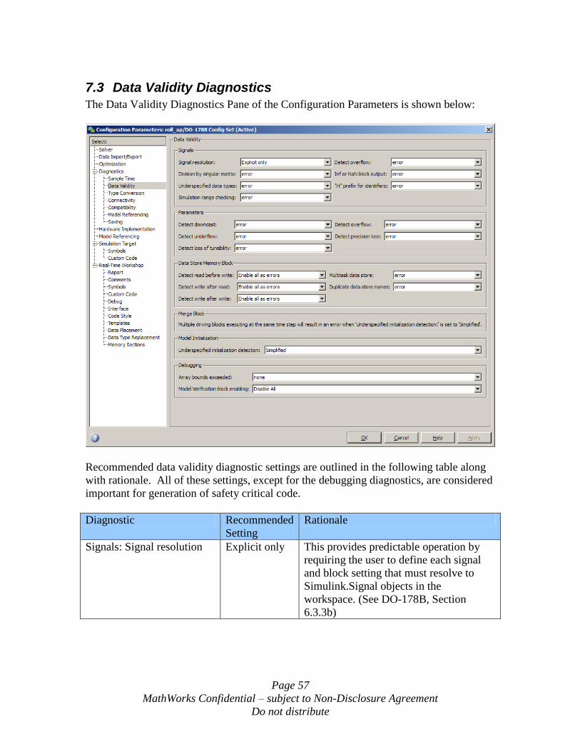
Page 57
MathWorks Confidential – subject to Non-Disclosure Agreement
Do not distribute
7.3 Data Validity Diagnostics
The Data Validity Diagnostics Pane of the Configuration Parameters is shown below:
Recommended data validity diagnostic settings are outlined in the following table along
with rationale. All of these settings, except for the debugging diagnostics, are considered
important for generation of safety critical code.
Diagnostic Recommended
Setting
Rationale
Signals: Signal resolution Explicit only This provides predictable operation by
requiring the user to define each signal
and block setting that must resolve to
Simulink.Signal objects in the
workspace. (See DO-178B, Section
6.3.3b)
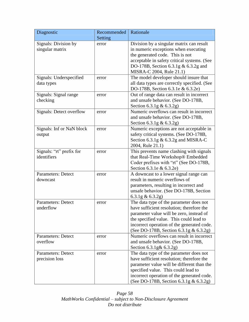
Page 58
MathWorks Confidential – subject to Non-Disclosure Agreement
Do not distribute
Diagnostic Recommended
Setting
Rationale
Signals: Division by
singular matrix
error Division by a singular matrix can result
in numeric exceptions when executing
the generated code. This is not
acceptable in safety critical systems. (See
DO-178B, Section 6.3.1g & 6.3.2g and
MISRA-C 2004, Rule 21.1)
Signals: Underspecified
data types
error The model developer should insure that
all data types are correctly specified. (See
DO-178B, Section 6.3.1e & 6.3.2e)
Signals: Signal range
checking
error Out of range data can result in incorrect
and unsafe behavior. (See DO-178B,
Section 6.3.1g & 6.3.2g)
Signals: Detect overflow error Numeric overflows can result in incorrect
and unsafe behavior. (See DO-178B,
Section 6.3.1g & 6.3.2g)
Signals: Inf or NaN block
output
error Numeric exceptions are not acceptable in
safety critical systems. (See DO-178B,
Section 6.3.1g & 6.3.2g and MISRA-C
2004, Rule 21.1)
Signals: “rt” prefix for
identifiers
error This prevents name clashing with signals
that Real-Time Workshop® Embedded
Coder prefixes with “rt” (See DO-178B,
Section 6.3.1e & 6.3.2e)
Parameters: Detect
downcast
error A downcast to a lower signal range can
result in numeric overflows of
parameters, resulting in incorrect and
unsafe behavior. (See DO-178B, Section
6.3.1g & 6.3.2g)
Parameters: Detect
underflow
error The data type of the parameter does not
have sufficient resolution; therefore the
parameter value will be zero, instead of
the specified value. This could lead to
incorrect operation of the generated code.
(See DO-178B, Section 6.3.1g & 6.3.2g)
Parameters: Detect
overflow
error Numeric overflows can result in incorrect
and unsafe behavior. (See DO-178B,
Section 6.3.1g& 6.3.2g)
Parameters: Detect
precision loss
error The data type of the parameter does not
have sufficient resolution; therefore the
parameter value will be different than the
specified value. This could lead to
incorrect operation of the generated code.
(See DO-178B, Section 6.3.1g & 6.3.2g)
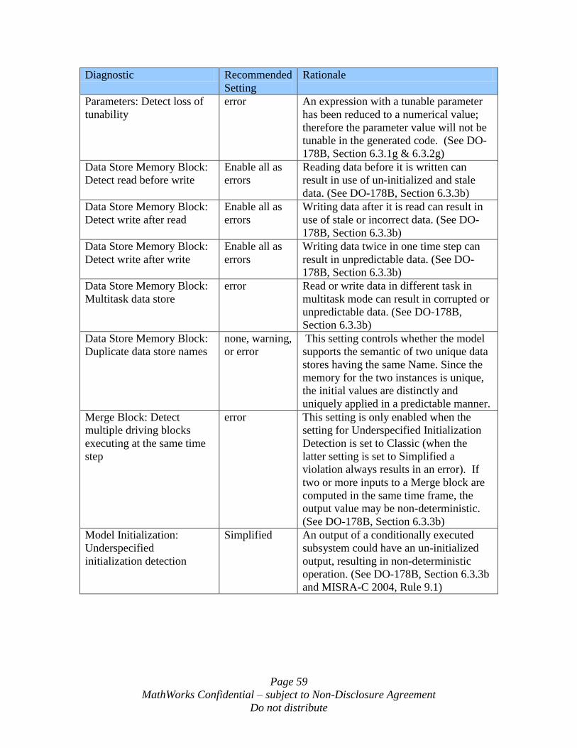
Page 59
MathWorks Confidential – subject to Non-Disclosure Agreement
Do not distribute
Diagnostic Recommended
Setting
Rationale
Parameters: Detect loss of
tunability
error An expression with a tunable parameter
has been reduced to a numerical value;
therefore the parameter value will not be
tunable in the generated code. (See DO-
178B, Section 6.3.1g & 6.3.2g)
Data Store Memory Block:
Detect read before write
Enable all as
errors
Reading data before it is written can
result in use of un-initialized and stale
data. (See DO-178B, Section 6.3.3b)
Data Store Memory Block:
Detect write after read
Enable all as
errors
Writing data after it is read can result in
use of stale or incorrect data. (See DO-
178B, Section 6.3.3b)
Data Store Memory Block:
Detect write after write
Enable all as
errors
Writing data twice in one time step can
result in unpredictable data. (See DO-
178B, Section 6.3.3b)
Data Store Memory Block:
Multitask data store
error Read or write data in different task in
multitask mode can result in corrupted or
unpredictable data. (See DO-178B,
Section 6.3.3b)
Data Store Memory Block:
Duplicate data store names
none, warning,
or error
This setting controls whether the model
supports the semantic of two unique data
stores having the same Name. Since the
memory for the two instances is unique,
the initial values are distinctly and
uniquely applied in a predictable manner.
Merge Block: Detect
multiple driving blocks
executing at the same time
step
error This setting is only enabled when the
setting for Underspecified Initialization
Detection is set to Classic (when the
latter setting is set to Simplified a
violation always results in an error). If
two or more inputs to a Merge block are
computed in the same time frame, the
output value may be non-deterministic.
(See DO-178B, Section 6.3.3b)
Model Initialization:
Underspecified
initialization detection
Simplified An output of a conditionally executed
subsystem could have an un-initialized
output, resulting in non-deterministic
operation. (See DO-178B, Section 6.3.3b
and MISRA-C 2004, Rule 9.1)
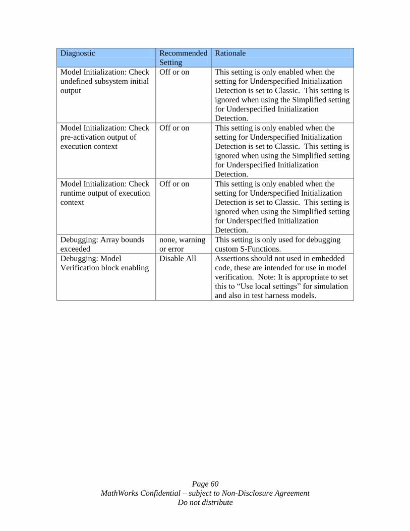
Page 60
MathWorks Confidential – subject to Non-Disclosure Agreement
Do not distribute
Diagnostic Recommended
Setting
Rationale
Model Initialization: Check
undefined subsystem initial
output
Off or on This setting is only enabled when the
setting for Underspecified Initialization
Detection is set to Classic. This setting is
ignored when using the Simplified setting
for Underspecified Initialization
Detection.
Model Initialization: Check
pre-activation output of
execution context
Off or on This setting is only enabled when the
setting for Underspecified Initialization
Detection is set to Classic. This setting is
ignored when using the Simplified setting
for Underspecified Initialization
Detection.
Model Initialization: Check
runtime output of execution
context
Off or on This setting is only enabled when the
setting for Underspecified Initialization
Detection is set to Classic. This setting is
ignored when using the Simplified setting
for Underspecified Initialization
Detection.
Debugging: Array bounds
exceeded
none, warning
or error
This setting is only used for debugging
custom S-Functions.
Debugging: Model
Verification block enabling
Disable All Assertions should not used in embedded
code, these are intended for use in model
verification. Note: It is appropriate to set
this to “Use local settings” for simulation
and also in test harness models.
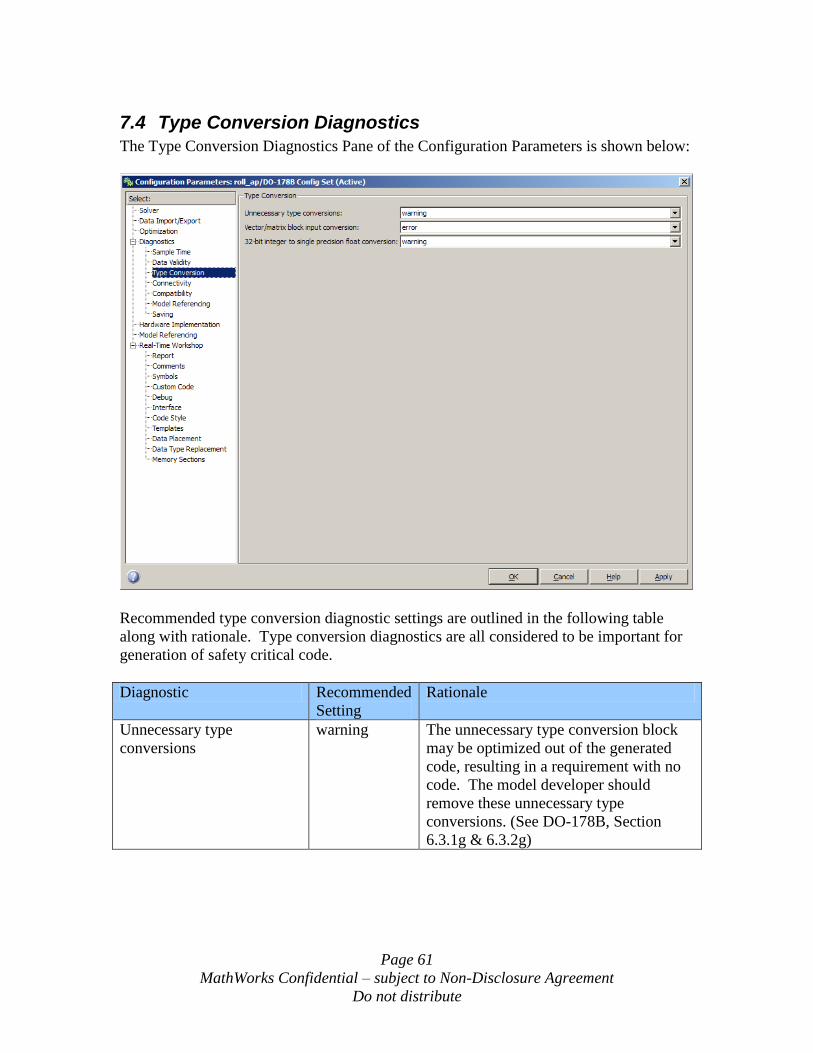
Page 61
MathWorks Confidential – subject to Non-Disclosure Agreement
Do not distribute
7.4 Type Conversion Diagnostics
The Type Conversion Diagnostics Pane of the Configuration Parameters is shown below:
Recommended type conversion diagnostic settings are outlined in the following table
along with rationale. Type conversion diagnostics are all considered to be important for
generation of safety critical code.
Diagnostic Recommended
Setting
Rationale
Unnecessary type
conversions
warning The unnecessary type conversion block
may be optimized out of the generated
code, resulting in a requirement with no
code. The model developer should
remove these unnecessary type
conversions. (See DO-178B, Section
6.3.1g & 6.3.2g)
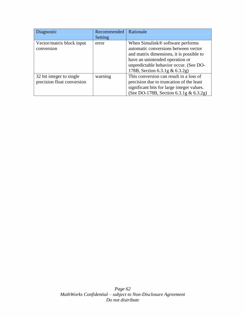
Page 62
MathWorks Confidential – subject to Non-Disclosure Agreement
Do not distribute
Diagnostic Recommended
Setting
Rationale
Vector/matrix block input
conversion
error When Simulink® software performs
automatic conversions between vector
and matrix dimensions, it is possible to
have an unintended operation or
unpredictable behavior occur. (See DO-
178B, Section 6.3.1g & 6.3.2g)
32 bit integer to single
precision float conversion
warning This conversion can result in a loss of
precision due to truncation of the least
significant bits for large integer values.
(See DO-178B, Section 6.3.1g & 6.3.2g)
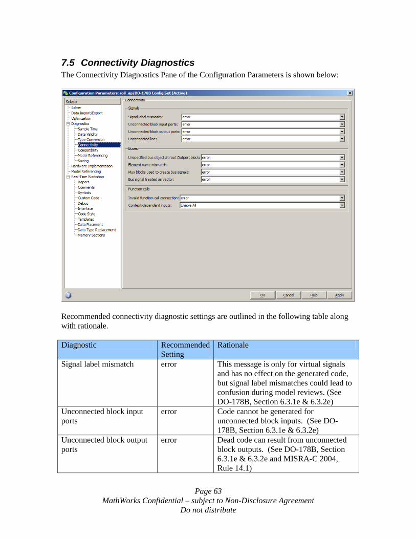
Page 63
MathWorks Confidential – subject to Non-Disclosure Agreement
Do not distribute
7.5 Connectivity Diagnostics
The Connectivity Diagnostics Pane of the Configuration Parameters is shown below:
Recommended connectivity diagnostic settings are outlined in the following table along
with rationale.
Diagnostic Recommended
Setting
Rationale
Signal label mismatch error This message is only for virtual signals
and has no effect on the generated code,
but signal label mismatches could lead to
confusion during model reviews. (See
DO-178B, Section 6.3.1e & 6.3.2e)
Unconnected block input
ports
error Code cannot be generated for
unconnected block inputs. (See DO-
178B, Section 6.3.1e & 6.3.2e)
Unconnected block output
ports
error Dead code can result from unconnected
block outputs. (See DO-178B, Section
6.3.1e & 6.3.2e and MISRA-C 2004,
Rule 14.1)
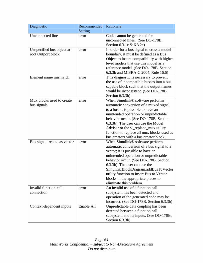
Page 64
MathWorks Confidential – subject to Non-Disclosure Agreement
Do not distribute
Diagnostic Recommended
Setting
Rationale
Unconnected line error Code cannot be generated for
unconnected lines. (See DO-178B,
Section 6.3.1e & 6.3.2e)
Unspecified bus object at
root Outport block
error In order for a bus signal to cross a model
boundary, it must be defined as a Bus
Object to insure compatibility with higher
level models that use this model as a
reference model. (See DO-178B, Section
6.3.3b and MISRA-C 2004, Rule 16.6)
Element name mismatch error This diagnostic is necessary to prevent
the use of incompatible busses into a bus
capable block such that the output names
would be inconsistent. (See DO-178B,
Section 6.3.3b)
Mux blocks used to create
bus signals
error When Simulink® software performs
automatic conversion of a muxed signal
to a bus; it is possible to have an
unintended operation or unpredictable
behavior occur. (See DO-178B, Section
6.3.3b) The user can use the Model
Advisor or the sl_replace_mux utility
function to replace all mux blocks used as
bus creators with a bus creator block.
Bus signal treated as vector error When Simulink® software performs
automatic conversion of a bus signal to a
vector; it is possible to have an
unintended operation or unpredictable
behavior occur. (See DO-178B, Section
6.3.3b) The user can use the
Simulink.BlockDiagram.addBusToVector
utility function to insert Bus to Vector
blocks in the appropriate places to
eliminate this problem.
Invalid function-call
connection
error An invalid use of a function call
subsystem has been detected and
operation of the generated code may be
incorrect. (See DO-178B, Section 6.3.3b)
Context-dependent inputs Enable All Unpredictable data coupling has been
detected between a function call
subsystem and its inputs. (See DO-178B,
Section 6.3.3b)
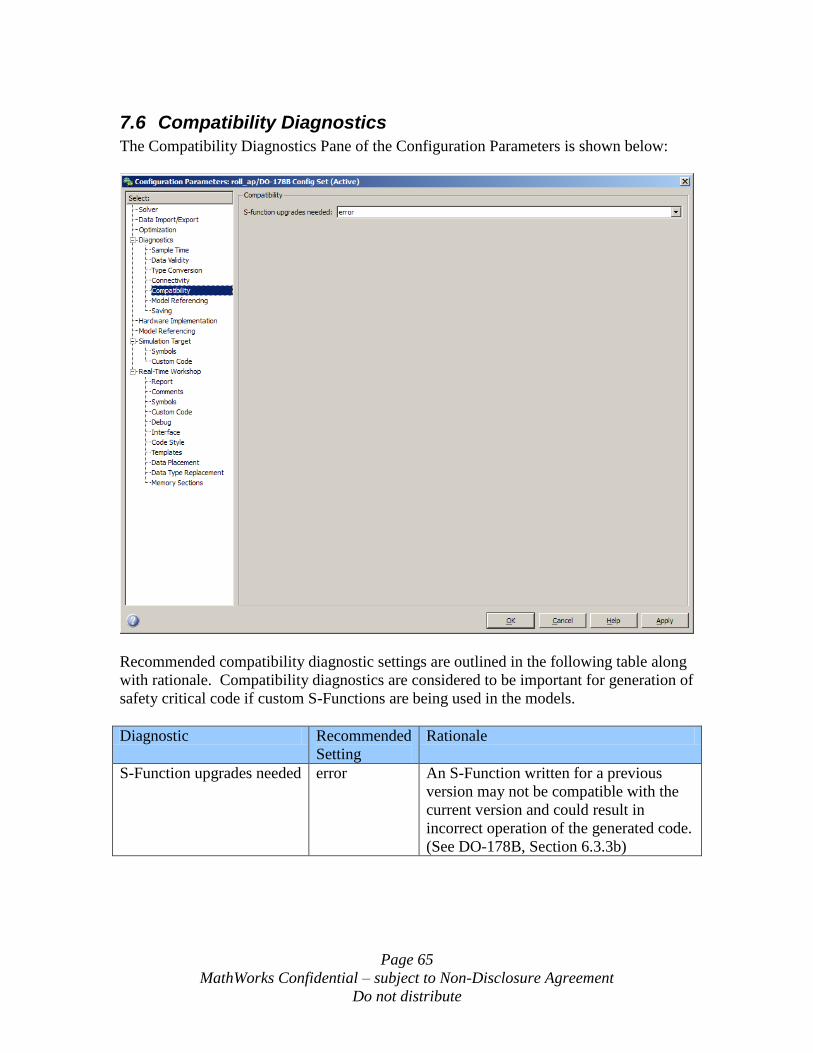
Page 65
MathWorks Confidential – subject to Non-Disclosure Agreement
Do not distribute
7.6 Compatibility Diagnostics
The Compatibility Diagnostics Pane of the Configuration Parameters is shown below:
Recommended compatibility diagnostic settings are outlined in the following table along
with rationale. Compatibility diagnostics are considered to be important for generation of
safety critical code if custom S-Functions are being used in the models.
Diagnostic Recommended
Setting
Rationale
S-Function upgrades needed error An S-Function written for a previous
version may not be compatible with the
current version and could result in
incorrect operation of the generated code.
(See DO-178B, Section 6.3.3b)
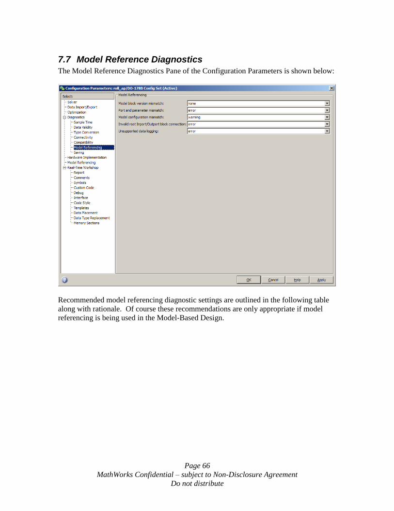
Page 66
MathWorks Confidential – subject to Non-Disclosure Agreement
Do not distribute
7.7 Model Reference Diagnostics
The Model Reference Diagnostics Pane of the Configuration Parameters is shown below:
Recommended model referencing diagnostic settings are outlined in the following table
along with rationale. Of course these recommendations are only appropriate if model
referencing is being used in the Model-Based Design.
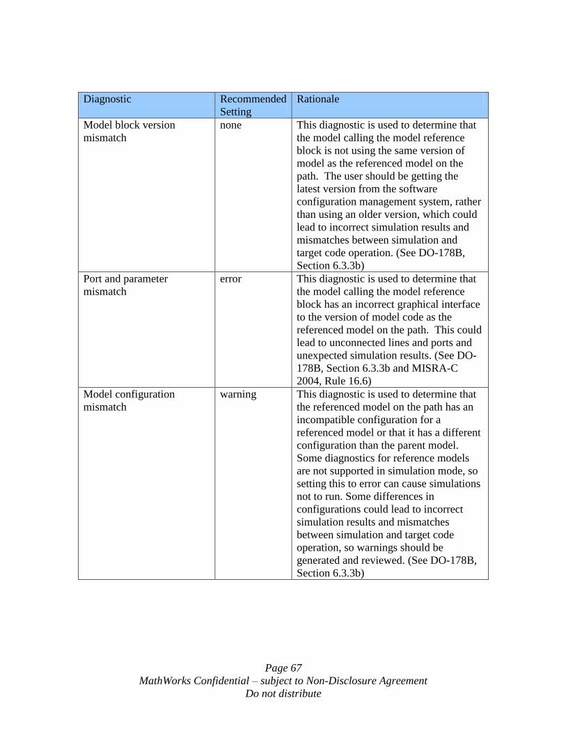
Page 67
MathWorks Confidential – subject to Non-Disclosure Agreement
Do not distribute
Diagnostic Recommended
Setting
Rationale
Model block version
mismatch
none This diagnostic is used to determine that
the model calling the model reference
block is not using the same version of
model as the referenced model on the
path. The user should be getting the
latest version from the software
configuration management system, rather
than using an older version, which could
lead to incorrect simulation results and
mismatches between simulation and
target code operation. (See DO-178B,
Section 6.3.3b)
Port and parameter
mismatch
error This diagnostic is used to determine that
the model calling the model reference
block has an incorrect graphical interface
to the version of model code as the
referenced model on the path. This could
lead to unconnected lines and ports and
unexpected simulation results. (See DO-
178B, Section 6.3.3b and MISRA-C
2004, Rule 16.6)
Model configuration
mismatch
warning This diagnostic is used to determine that
the referenced model on the path has an
incompatible configuration for a
referenced model or that it has a different
configuration than the parent model.
Some diagnostics for reference models
are not supported in simulation mode, so
setting this to error can cause simulations
not to run. Some differences in
configurations could lead to incorrect
simulation results and mismatches
between simulation and target code
operation, so warnings should be
generated and reviewed. (See DO-178B,
Section 6.3.3b)
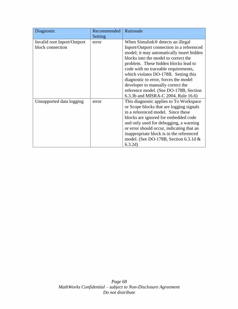
Page 68
MathWorks Confidential – subject to Non-Disclosure Agreement
Do not distribute
Diagnostic Recommended
Setting
Rationale
Invalid root Inport/Outport
block connection
error When Simulink® detects an illegal
Inport/Outport connection in a referenced
model; it may automatically insert hidden
blocks into the model to correct the
problem. These hidden blocks lead to
code with no traceable requirements,
which violates DO-178B. Setting this
diagnostic to error, forces the model
developer to manually correct the
reference model. (See DO-178B, Section
6.3.3b and MISRA-C 2004, Rule 16.6)
Unsupported data logging error This diagnostic applies to To Workspace
or Scope blocks that are logging signals
in a referenced model. Since these
blocks are ignored for embedded code
and only used for debugging, a warning
or error should occur, indicating that an
inappropriate block is in the referenced
model. (See DO-178B, Section 6.3.1d &
6.3.2d)
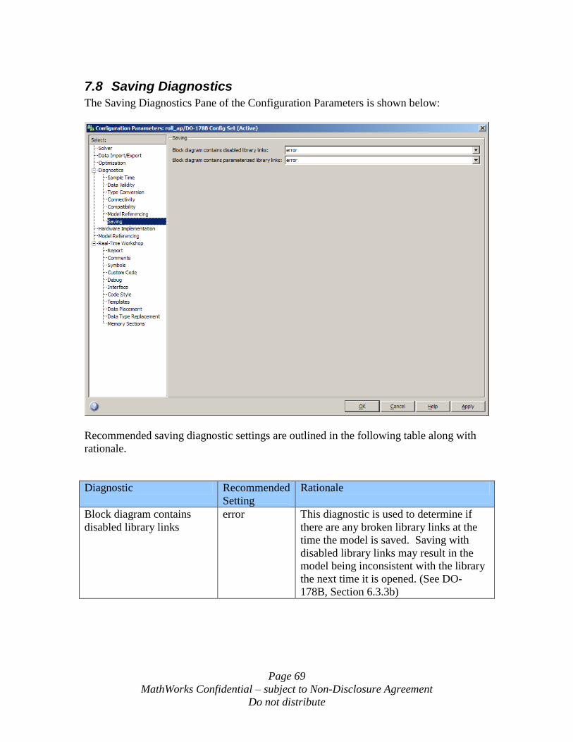
Page 69
MathWorks Confidential – subject to Non-Disclosure Agreement
Do not distribute
7.8 Saving Diagnostics
The Saving Diagnostics Pane of the Configuration Parameters is shown below:
Recommended saving diagnostic settings are outlined in the following table along with
rationale.
Diagnostic Recommended
Setting
Rationale
Block diagram contains
disabled library links
error This diagnostic is used to determine if
there are any broken library links at the
time the model is saved. Saving with
disabled library links may result in the
model being inconsistent with the library
the next time it is opened. (See DO-
178B, Section 6.3.3b)
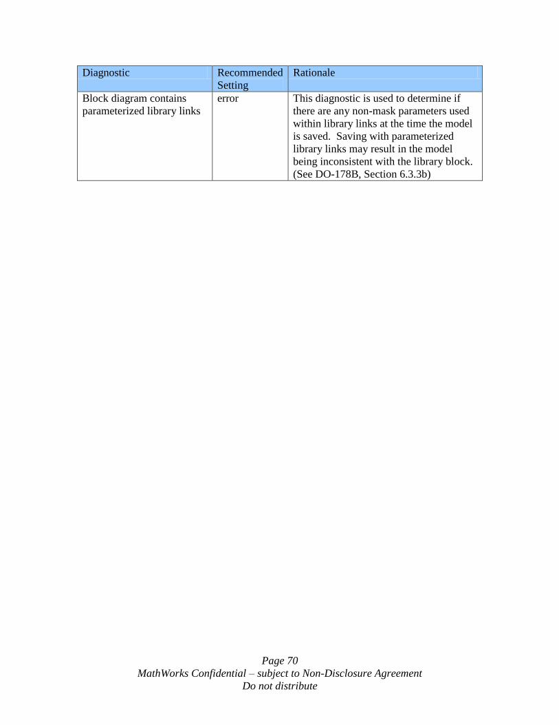
Page 70
MathWorks Confidential – subject to Non-Disclosure Agreement
Do not distribute
Diagnostic Recommended
Setting
Rationale
Block diagram contains
parameterized library links
error This diagnostic is used to determine if
there are any non-mask parameters used
within library links at the time the model
is saved. Saving with parameterized
library links may result in the model
being inconsistent with the library block.
(See DO-178B, Section 6.3.3b)
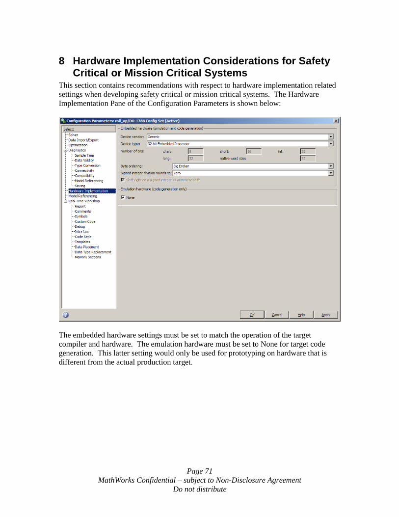
Page 71
MathWorks Confidential – subject to Non-Disclosure Agreement
Do not distribute
8 Hardware Implementation Considerations for Safety Critical or Mission Critical Systems
This section contains recommendations with respect to hardware implementation related
settings when developing safety critical or mission critical systems. The Hardware
Implementation Pane of the Configuration Parameters is shown below:
The embedded hardware settings must be set to match the operation of the target
compiler and hardware. The emulation hardware must be set to None for target code
generation. This latter setting would only be used for prototyping on hardware that is
different from the actual production target.
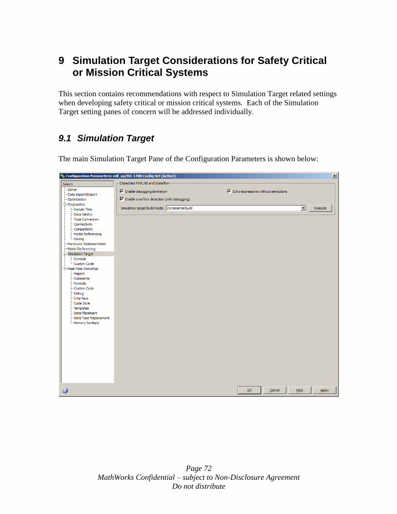
Page 72
MathWorks Confidential – subject to Non-Disclosure Agreement
Do not distribute
9 Simulation Target Considerations for Safety Critical or Mission Critical Systems
This section contains recommendations with respect to Simulation Target related settings
when developing safety critical or mission critical systems. Each of the Simulation
Target setting panes of concern will be addressed individually.
9.1 Simulation Target
The main Simulation Target Pane of the Configuration Parameters is shown below:
Page 73
MathWorks Confidential – subject to Non-Disclosure Agreement
Do not distribute
Recommended Simulation Target option settings are outlined in the following table along
with rationale.
Option Recommended
Setting
Rationale
Enable
debugging/animation
on In order to provide diagnostic coverage
specified in sections 13.2 and 13.3 during
simulation, the “Enable
debugging/animation” setting must be
checked. This will not affect the
embedded code, only the simulation
code.
Echo expressions without
semicolons
Off or on This setting has no effect on safety and is
only used during simulation.
Enable overflow detection
(with debugging)
on This setting should be set so that any
numeric overflows are reported during
simulation. Numeric overflows can
result in incorrect and unsafe behavior.
(See DO-178B, Section 6.4.2.2 & 6.4.3)
Simulation target build
mode
Incremental
build,
Rebuild all,
Make without
generating
code,
Clean all, or
Clean objects
Method of building of simulation code
has no effect on safety and does not
affect the generation of the embedded
code.
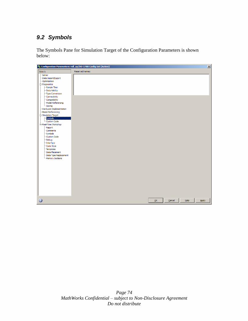
Page 74
MathWorks Confidential – subject to Non-Disclosure Agreement
Do not distribute
9.2 Symbols
The Symbols Pane for Simulation Target of the Configuration Parameters is shown
below:
Page 75
MathWorks Confidential – subject to Non-Disclosure Agreement
Do not distribute
Recommended Symbols option settings are outlined in the following table along with
rationale.
Option Recommended
Setting
Rationale
Reserved names Empty or any
valid reserved
name
expression
that does not
contain a
Real-Time
Workshop®
keyword
The reserved names correspond to
functions or variables that may be
contained in custom code. Real-Time
Workshop® will mangle any names that
may conflict with reserved names in the
generated code.
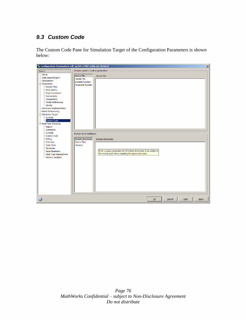
Page 76
MathWorks Confidential – subject to Non-Disclosure Agreement
Do not distribute
9.3 Custom Code
The Custom Code Pane for Simulation Target of the Configuration Parameters is shown
below:
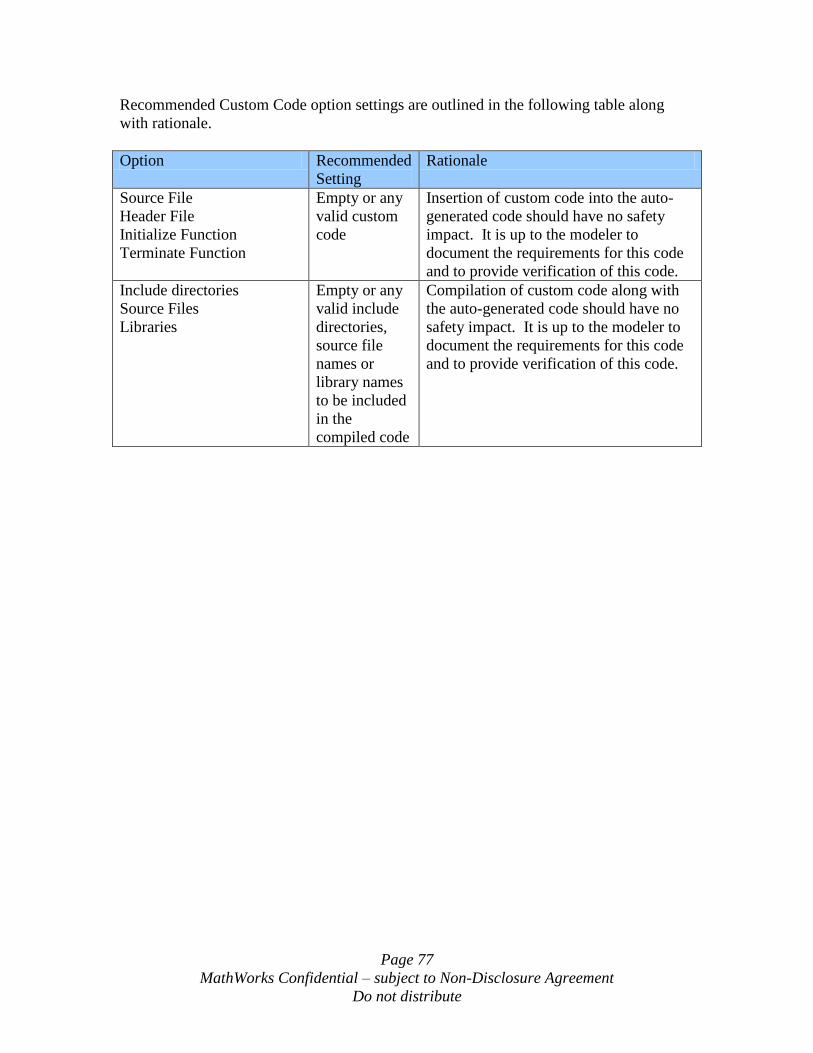
Page 77
MathWorks Confidential – subject to Non-Disclosure Agreement
Do not distribute
Recommended Custom Code option settings are outlined in the following table along
with rationale.
Option Recommended
Setting
Rationale
Source File
Header File
Initialize Function
Terminate Function
Empty or any
valid custom
code
Insertion of custom code into the auto-
generated code should have no safety
impact. It is up to the modeler to
document the requirements for this code
and to provide verification of this code.
Include directories
Source Files
Libraries
Empty or any
valid include
directories,
source file
names or
library names
to be included
in the
compiled code
Compilation of custom code along with
the auto-generated code should have no
safety impact. It is up to the modeler to
document the requirements for this code
and to provide verification of this code.
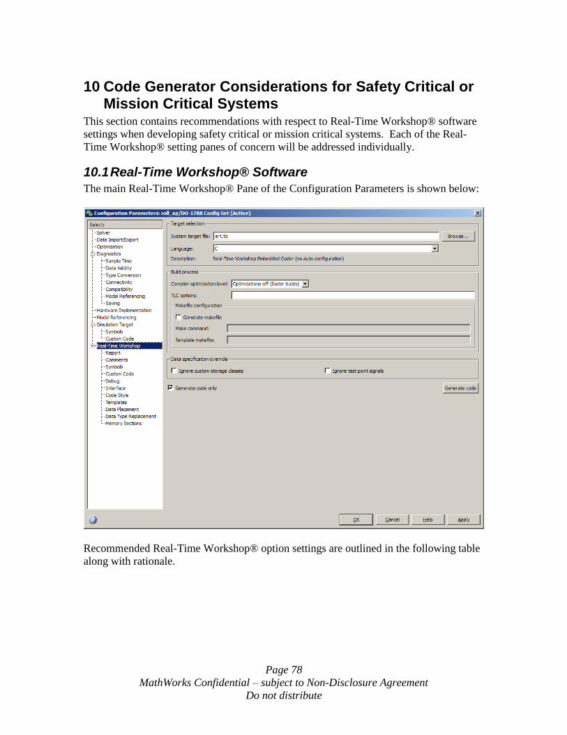
Page 78
MathWorks Confidential – subject to Non-Disclosure Agreement
Do not distribute
10 Code Generator Considerations for Safety Critical or Mission Critical Systems
This section contains recommendations with respect to Real-Time Workshop® software
settings when developing safety critical or mission critical systems. Each of the Real-
Time Workshop® setting panes of concern will be addressed individually.
10.1 Real-Time Workshop® Software
The main Real-Time Workshop® Pane of the Configuration Parameters is shown below:
Recommended Real-Time Workshop® option settings are outlined in the following table
along with rationale.
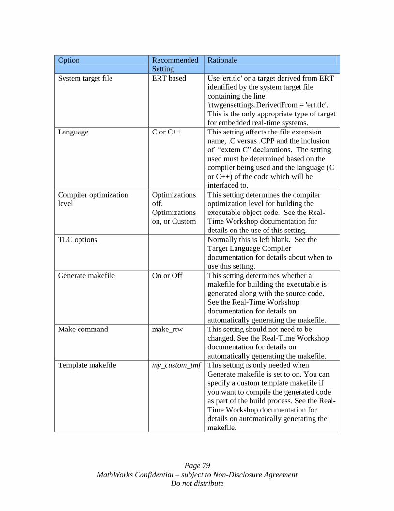
Page 79
MathWorks Confidential – subject to Non-Disclosure Agreement
Do not distribute
Option Recommended
Setting
Rationale
System target file ERT based Use 'ert.tlc' or a target derived from ERT
identified by the system target file
containing the line
'rtwgensettings.DerivedFrom = 'ert.tlc'.
This is the only appropriate type of target
for embedded real-time systems.
Language C or C++ This setting affects the file extension
name, .C versus .CPP and the inclusion
of “extern C” declarations. The setting
used must be determined based on the
compiler being used and the language (C
or C++) of the code which will be
interfaced to.
Compiler optimization
level
Optimizations
off,
Optimizations
on, or Custom
This setting determines the compiler
optimization level for building the
executable object code. See the Real-
Time Workshop documentation for
details on the use of this setting.
TLC options Normally this is left blank. See the
Target Language Compiler
documentation for details about when to
use this setting.
Generate makefile On or Off This setting determines whether a
makefile for building the executable is
generated along with the source code.
See the Real-Time Workshop
documentation for details on
automatically generating the makefile.
Make command make_rtw This setting should not need to be
changed. See the Real-Time Workshop
documentation for details on
automatically generating the makefile.
Template makefile my_custom_tmf This setting is only needed when
Generate makefile is set to on. You can
specify a custom template makefile if
you want to compile the generated code
as part of the build process. See the Real-
Time Workshop documentation for
details on automatically generating the
makefile.
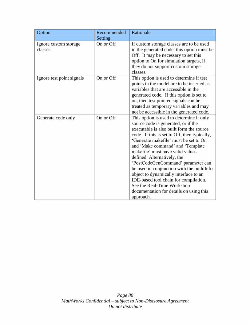
Page 80
MathWorks Confidential – subject to Non-Disclosure Agreement
Do not distribute
Option Recommended
Setting
Rationale
Ignore custom storage
classes
On or Off If custom storage classes are to be used
in the generated code, this option must be
Off. It may be necessary to set this
option to On for simulation targets, if
they do not support custom storage
classes.
Ignore test point signals On or Off This option is used to determine if test
points in the model are to be inserted as
variables that are accessible in the
generated code. If this option is set to
on, then test pointed signals can be
treated as temporary variables and may
not be accessible in the generated code.
Generate code only On or Off This option is used to determine if only
source code is generated, or if the
executable is also built form the source
code. If this is set to Off, then typically,
„Generate makefile‟ must be set to On
and „Make command‟ and „Template
makefile‟ must have valid values
defined. Alternatively, the
„PostCodeGenCommand‟ parameter can
be used in conjunction with the buildInfo
object to dynamically interface to an
IDE-based tool chain for compilation.
See the Real-Time Workshop
documentation for details on using this
approach.
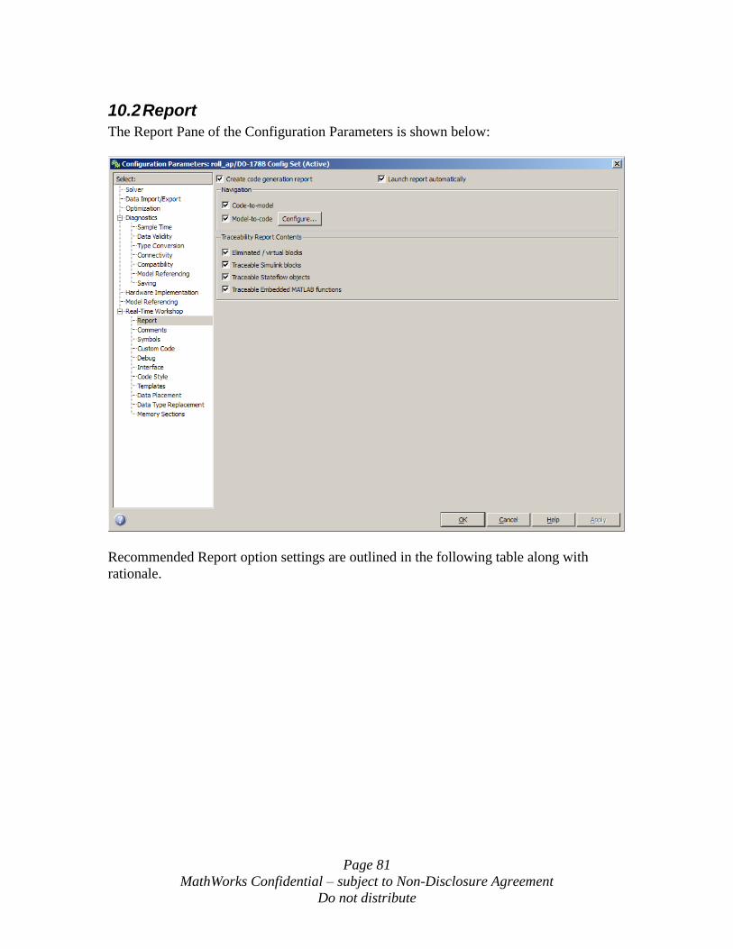
Page 81
MathWorks Confidential – subject to Non-Disclosure Agreement
Do not distribute
10.2 Report
The Report Pane of the Configuration Parameters is shown below:
Recommended Report option settings are outlined in the following table along with
rationale.
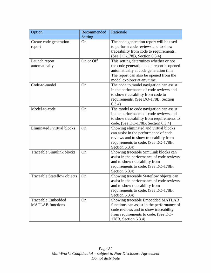
Page 82
MathWorks Confidential – subject to Non-Disclosure Agreement
Do not distribute
Option Recommended
Setting
Rationale
Create code generation
report
On The code generation report will be used
to perform code reviews and to show
traceability from code to requirements.
(See DO-178B, Section 6.3.4)
Launch report
automatically
On or Off This setting determines whether or not
the code generation code report is opened
automatically at code generation time.
The report can also be opened from the
model explorer at any time.
Code-to-model On The code to model navigation can assist
in the performance of code reviews and
to show traceability from code to
requirements. (See DO-178B, Section
6.3.4)
Model-to-code On The model to code navigation can assist
in the performance of code reviews and
to show traceability from requirements to
code. (See DO-178B, Section 6.3.4)
Eliminated / virtual blocks On Showing eliminated and virtual blocks
can assist in the performance of code
reviews and to show traceability from
requirements to code. (See DO-178B,
Section 6.3.4)
Traceable Simulink blocks On Showing traceable Simulink blocks can
assist in the performance of code reviews
and to show traceability from
requirements to code. (See DO-178B,
Section 6.3.4)
Traceable Stateflow objects On Showing traceable Stateflow objects can
assist in the performance of code reviews
and to show traceability from
requirements to code. (See DO-178B,
Section 6.3.4)
Traceable Embedded
MATLAB functions
On Showing traceable Embedded MATLAB
functions can assist in the performance of
code reviews and to show traceability
from requirements to code. (See DO-
178B, Section 6.3.4)
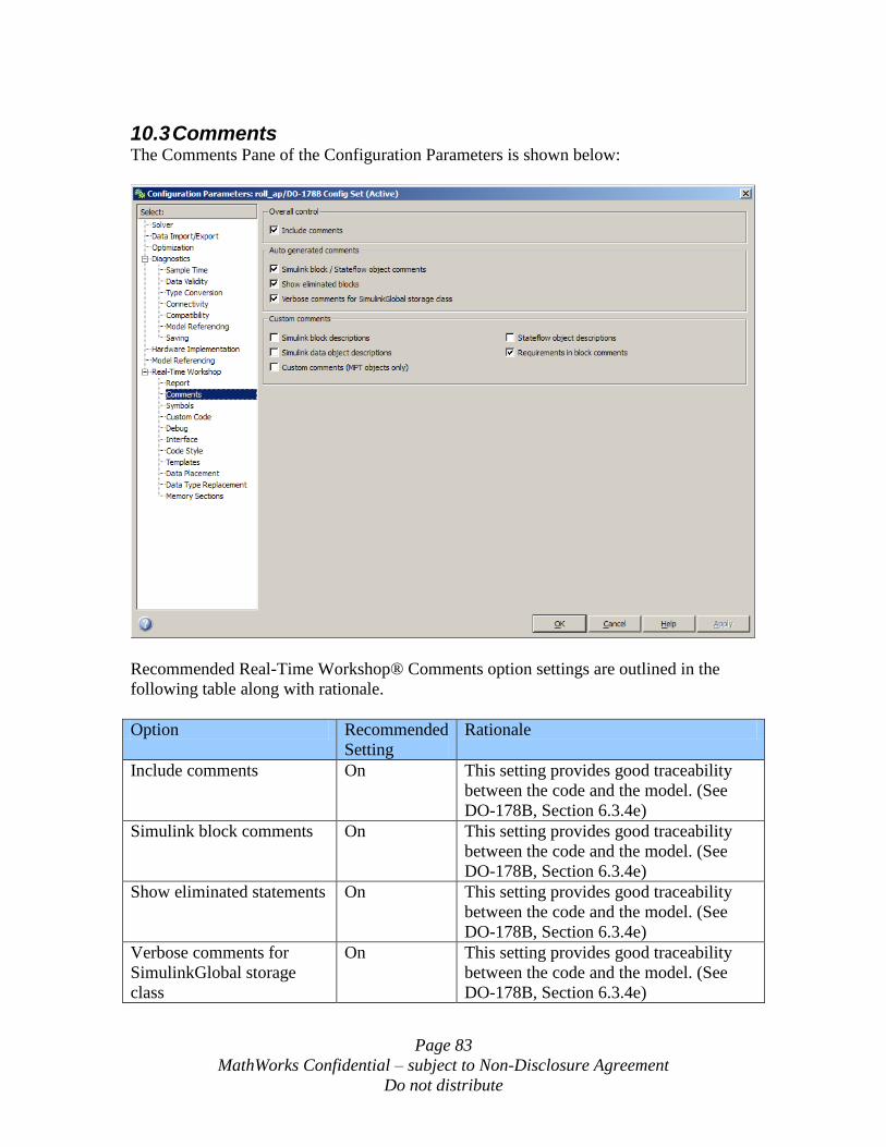
Page 83
MathWorks Confidential – subject to Non-Disclosure Agreement
Do not distribute
10.3 Comments
The Comments Pane of the Configuration Parameters is shown below:
Recommended Real-Time Workshop® Comments option settings are outlined in the
following table along with rationale.
Option Recommended
Setting
Rationale
Include comments On This setting provides good traceability
between the code and the model. (See
DO-178B, Section 6.3.4e)
Simulink block comments On This setting provides good traceability
between the code and the model. (See
DO-178B, Section 6.3.4e)
Show eliminated statements On This setting provides good traceability
between the code and the model. (See
DO-178B, Section 6.3.4e)
Verbose comments for
SimulinkGlobal storage
class
On This setting provides good traceability
between the code and the model. (See
DO-178B, Section 6.3.4e)
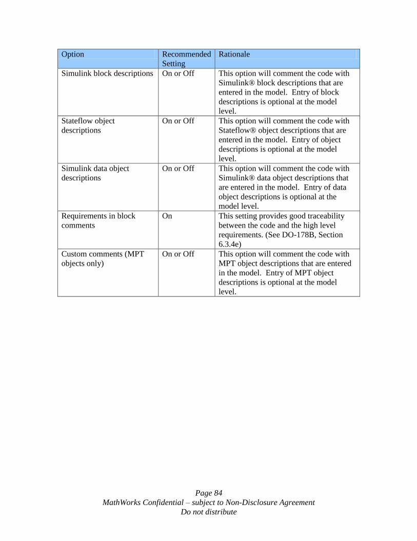
Page 84
MathWorks Confidential – subject to Non-Disclosure Agreement
Do not distribute
Option Recommended
Setting
Rationale
Simulink block descriptions On or Off This option will comment the code with
Simulink® block descriptions that are
entered in the model. Entry of block
descriptions is optional at the model
level.
Stateflow object
descriptions
On or Off This option will comment the code with
Stateflow® object descriptions that are
entered in the model. Entry of object
descriptions is optional at the model
level.
Simulink data object
descriptions
On or Off This option will comment the code with
Simulink® data object descriptions that
are entered in the model. Entry of data
object descriptions is optional at the
model level.
Requirements in block
comments
On This setting provides good traceability
between the code and the high level
requirements. (See DO-178B, Section
6.3.4e)
Custom comments (MPT
objects only)
On or Off This option will comment the code with
MPT object descriptions that are entered
in the model. Entry of MPT object
descriptions is optional at the model
level.
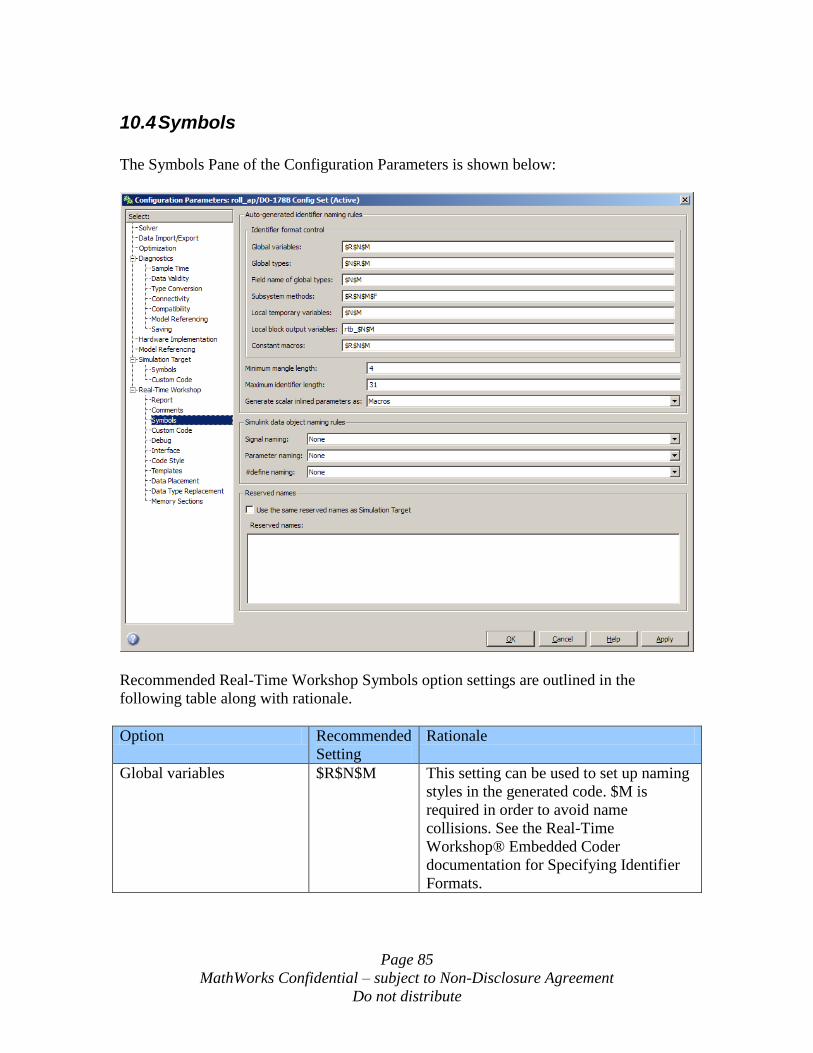
Page 85
MathWorks Confidential – subject to Non-Disclosure Agreement
Do not distribute
10.4 Symbols
The Symbols Pane of the Configuration Parameters is shown below:
Recommended Real-Time Workshop Symbols option settings are outlined in the
following table along with rationale.
Option Recommended
Setting
Rationale
Global variables $R$N$M This setting can be used to set up naming
styles in the generated code. $M is
required in order to avoid name
collisions. See the Real-Time
Workshop® Embedded Coder
documentation for Specifying Identifier
Formats.
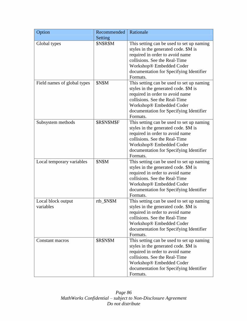
Page 86
MathWorks Confidential – subject to Non-Disclosure Agreement
Do not distribute
Option Recommended
Setting
Rationale
Global types $N$R$M This setting can be used to set up naming
styles in the generated code. $M is
required in order to avoid name
collisions. See the Real-Time
Workshop® Embedded Coder
documentation for Specifying Identifier
Formats.
Field names of global types $N$M This setting can be used to set up naming
styles in the generated code. $M is
required in order to avoid name
collisions. See the Real-Time
Workshop® Embedded Coder
documentation for Specifying Identifier
Formats.
Subsystem methods $R$N$M$F This setting can be used to set up naming
styles in the generated code. $M is
required in order to avoid name
collisions. See the Real-Time
Workshop® Embedded Coder
documentation for Specifying Identifier
Formats.
Local temporary variables $N$M This setting can be used to set up naming
styles in the generated code. $M is
required in order to avoid name
collisions. See the Real-Time
Workshop® Embedded Coder
documentation for Specifying Identifier
Formats.
Local block output
variables
rtb_$N$M This setting can be used to set up naming
styles in the generated code. $M is
required in order to avoid name
collisions. See the Real-Time
Workshop® Embedded Coder
documentation for Specifying Identifier
Formats.
Constant macros $R$N$M This setting can be used to set up naming
styles in the generated code. $M is
required in order to avoid name
collisions. See the Real-Time
Workshop® Embedded Coder
documentation for Specifying Identifier
Formats.
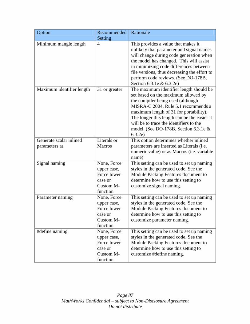
Page 87
MathWorks Confidential – subject to Non-Disclosure Agreement
Do not distribute
Option Recommended
Setting
Rationale
Minimum mangle length 4 This provides a value that makes it
unlikely that parameter and signal names
will change during code generation when
the model has changed. This will assist
in minimizing code differences between
file versions, thus decreasing the effort to
perform code reviews. (See DO-178B,
Section 6.3.1e & 6.3.2e)
Maximum identifier length 31 or greater The maximum identifier length should be
set based on the maximum allowed by
the compiler being used (although
MISRA-C 2004, Rule 5.1 recommends a
maximum length of 31 for portability).
The longer this length can be the easier it
will be to trace the identifiers to the
model. (See DO-178B, Section 6.3.1e &
6.3.2e)
Generate scalar inlined
parameters as
Literals or
Macros
This option determines whether inlined
parameters are inserted as Literals (i.e.
numeric value) or as Macros (i.e. variable
name)
Signal naming None, Force
upper case,
Force lower
case or
Custom M-
function
This setting can be used to set up naming
styles in the generated code. See the
Module Packing Features document to
determine how to use this setting to
customize signal naming.
Parameter naming None, Force
upper case,
Force lower
case or
Custom M-
function
This setting can be used to set up naming
styles in the generated code. See the
Module Packing Features document to
determine how to use this setting to
customize parameter naming.
#define naming None, Force
upper case,
Force lower
case or
Custom M-
function
This setting can be used to set up naming
styles in the generated code. See the
Module Packing Features document to
determine how to use this setting to
customize #define naming.
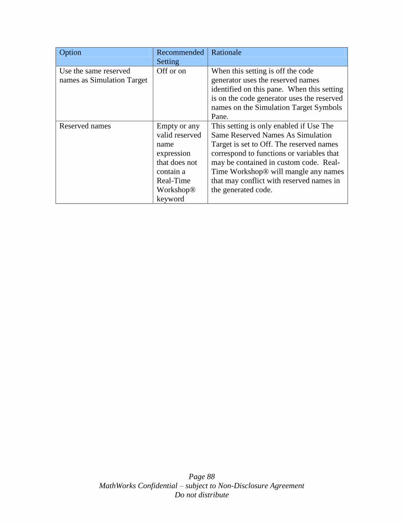
Page 88
MathWorks Confidential – subject to Non-Disclosure Agreement
Do not distribute
Option Recommended
Setting
Rationale
Use the same reserved
names as Simulation Target
Off or on When this setting is off the code
generator uses the reserved names
identified on this pane. When this setting
is on the code generator uses the reserved
names on the Simulation Target Symbols
Pane.
Reserved names Empty or any
valid reserved
name
expression
that does not
contain a
Real-Time
Workshop®
keyword
This setting is only enabled if Use The
Same Reserved Names As Simulation
Target is set to Off. The reserved names
correspond to functions or variables that
may be contained in custom code. Real-
Time Workshop® will mangle any names
that may conflict with reserved names in
the generated code.
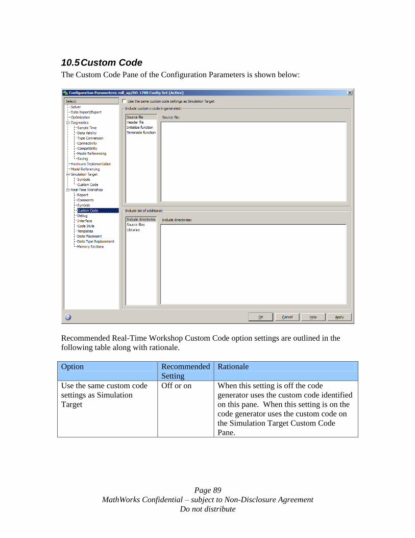
Page 89
MathWorks Confidential – subject to Non-Disclosure Agreement
Do not distribute
10.5 Custom Code
The Custom Code Pane of the Configuration Parameters is shown below:
Recommended Real-Time Workshop Custom Code option settings are outlined in the
following table along with rationale.
Option Recommended
Setting
Rationale
Use the same custom code
settings as Simulation
Target
Off or on When this setting is off the code
generator uses the custom code identified
on this pane. When this setting is on the
code generator uses the custom code on
the Simulation Target Custom Code
Pane.
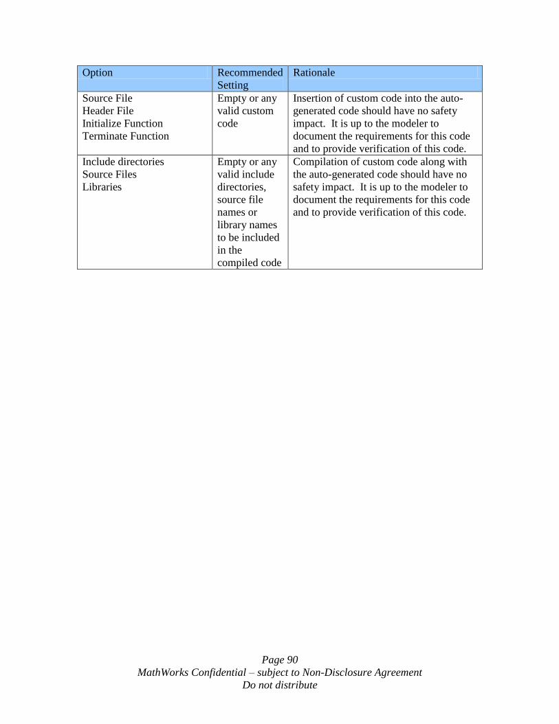
Page 90
MathWorks Confidential – subject to Non-Disclosure Agreement
Do not distribute
Option Recommended
Setting
Rationale
Source File
Header File
Initialize Function
Terminate Function
Empty or any
valid custom
code
Insertion of custom code into the auto-
generated code should have no safety
impact. It is up to the modeler to
document the requirements for this code
and to provide verification of this code.
Include directories
Source Files
Libraries
Empty or any
valid include
directories,
source file
names or
library names
to be included
in the
compiled code
Compilation of custom code along with
the auto-generated code should have no
safety impact. It is up to the modeler to
document the requirements for this code
and to provide verification of this code.
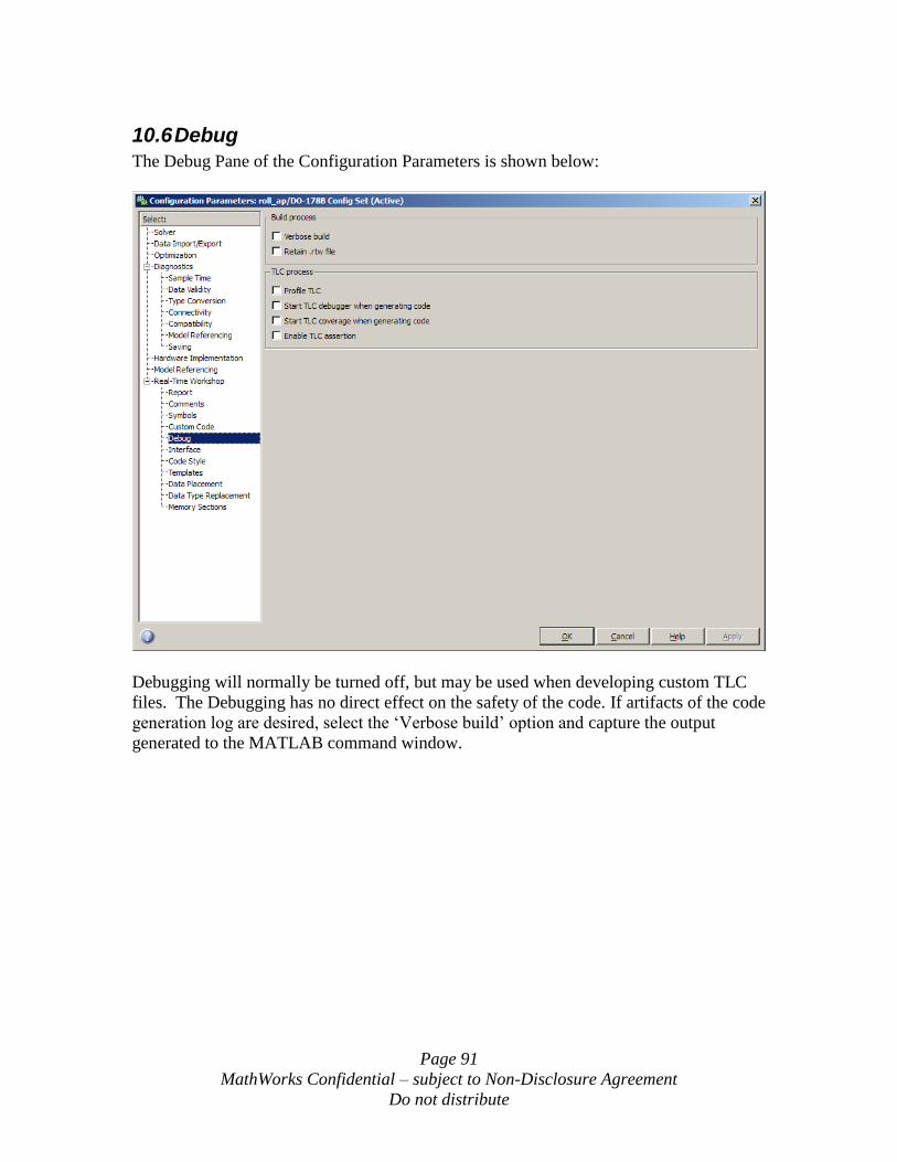
Page 91
MathWorks Confidential – subject to Non-Disclosure Agreement
Do not distribute
10.6 Debug
The Debug Pane of the Configuration Parameters is shown below:
Debugging will normally be turned off, but may be used when developing custom TLC
files. The Debugging has no direct effect on the safety of the code. If artifacts of the code
generation log are desired, select the „Verbose build‟ option and capture the output
generated to the MATLAB command window.
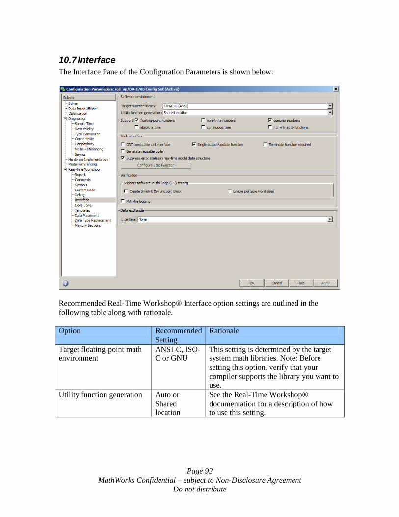
Page 92
MathWorks Confidential – subject to Non-Disclosure Agreement
Do not distribute
10.7 Interface
The Interface Pane of the Configuration Parameters is shown below:
Recommended Real-Time Workshop® Interface option settings are outlined in the
following table along with rationale.
Option Recommended
Setting
Rationale
Target floating-point math
environment
ANSI-C, ISO-
C or GNU
This setting is determined by the target
system math libraries. Note: Before
setting this option, verify that your
compiler supports the library you want to
use.
Utility function generation Auto or
Shared
location
See the Real-Time Workshop®
documentation for a description of how
to use this setting.
Page 93
MathWorks Confidential – subject to Non-Disclosure Agreement
Do not distribute
Option Recommended
Setting
Rationale
Support floating point
numbers
On or Off Normally this will be set to On, unless
the target processor only supports fixed
point, then it should be set to Off to
insure hardware compatibility. (See DO-
178B Section 6.3.1c, 6.3.2c & 6.3.3c)
Support non-finite numbers Off Support of non-finite numbers is
inappropriate for real-time safety critical
systems. (See DO-178B Section 6.3.1c &
6.3.2c)
Support complex numbers On or Off Set as appropriate for you application.
Support absolute time Off Support of absolute time is inappropriate
for real-time safety critical systems. (See
DO-178B Section 6.3.1c & 6.3.2c)
Support continuous time Off Support of continuous time is
inappropriate for real-time safety critical
systems. (See DO-178B Section 6.3.1c &
6.3.2c)
Support non-inlined S-
Functions
Off This option would require supporting
non-finite numbers which is
inappropriate for real-time safety critical
systems. (See DO-178B Section 6.3.1c &
6.3.2c)
GRT compatible call
interface
Off This option is not appropriate for real-
time embedded systems. (See DO-178B
Section 6.3.1c & 6.3.2c)
Single output/update
function
On Having a single call to the output and
update functions simplifies the interface
to the RTOS and simplifies verification
of the auto-generated code. (See DO-
178B Section 6.3.1c & 6.3.2c)
Terminate function required Off Terminate function is only used for
dynamic memory de-allocation, which is
not appropriate for real-time safety
critical systems. ((See DO-178B Section
6.3.1c & 6.3.2c and MISRA-C 2004,
Rule 20.4)
Generate reusable code On or Off This option affects the style of the code
interface. If the auto-generated code is
intended to be reused multiple times in
the same executable with different data
sets for each use, then this option must be
set to On. If the code is only to be used
once, then this option may be On or Off.
Page 94
MathWorks Confidential – subject to Non-Disclosure Agreement
Do not distribute
Option Recommended
Setting
Rationale
Suppress error status in
real-time model data
structure
On Not selecting this option will produce
extra code that may be unreachable and
therefore un-testable in the generated
code. (See DO-178B, Section 6. 3.1c &
6.3.2c and MISRA-C 2004, Rule 14.1)
Create Simulink (S-
Function) block
On or Off This option creates an S-Function
wrapper for the generated code so that it
can be tested during simulation using a
test harness. The generated model code
is unaffected by this option, only an
additional S-function interface file
(<modelname>_sf.c) is created.
Alternatively, model reference can be
used to test the code generated for a
Model block during a simulation,
however the target code for the Model
block will need to be generated
separately from the simulation code.
Enable portable word sizes On or Off This option allows the generated code to
be compiled for use with the S-Function
wrapper described above in this table,
even if the word size of the host machine
is different from the word size of the
target computer defined in the Hardware
Implementation pane of the
Configuration Parameters.
MAT-file data logging Off This option adds extra code to log test
point to a MAT file, which would not be
supported by the embedded target
platform. (See DO-178B Section 6.3.1c
& 6.3.2c) This option should only be
used in test harnesses, not in models used
for embedded target code generation.
Interface None This option allows extra interface code to
be generated to support signal
observation and parameter tuning on the
target platform. Any of the three options:
C-API, External Mode or ASAP2 may be
used during development, but it is
recommended that this software be
removed for the final production version.
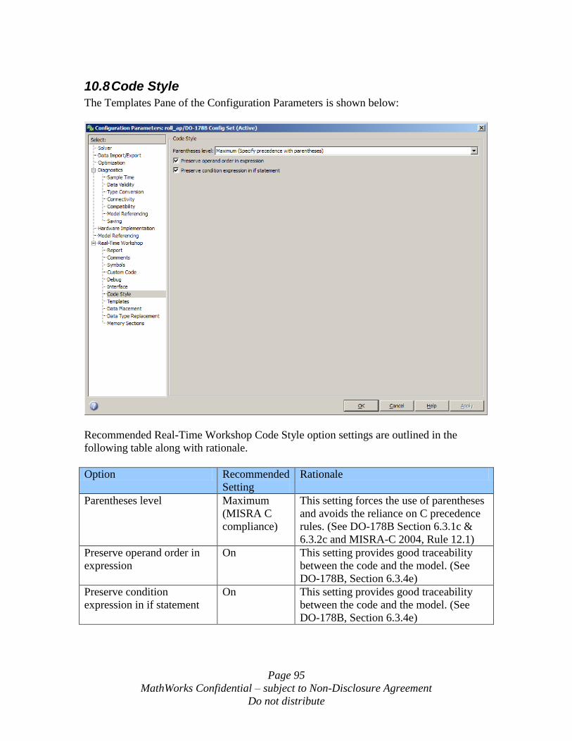
Page 95
MathWorks Confidential – subject to Non-Disclosure Agreement
Do not distribute
10.8 Code Style
The Templates Pane of the Configuration Parameters is shown below:
Recommended Real-Time Workshop Code Style option settings are outlined in the
following table along with rationale.
Option Recommended
Setting
Rationale
Parentheses level Maximum
(MISRA C
compliance)
This setting forces the use of parentheses
and avoids the reliance on C precedence
rules. (See DO-178B Section 6.3.1c &
6.3.2c and MISRA-C 2004, Rule 12.1)
Preserve operand order in
expression
On This setting provides good traceability
between the code and the model. (See
DO-178B, Section 6.3.4e)
Preserve condition
expression in if statement
On This setting provides good traceability
between the code and the model. (See
DO-178B, Section 6.3.4e)
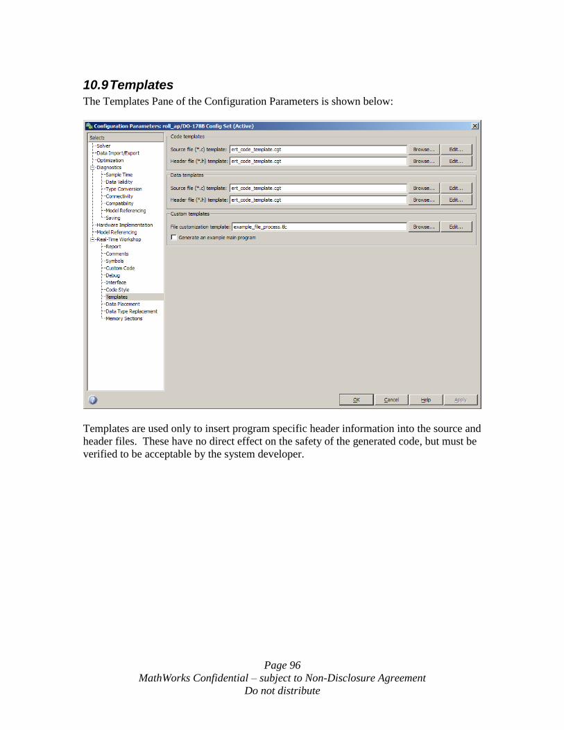
Page 96
MathWorks Confidential – subject to Non-Disclosure Agreement
Do not distribute
10.9 Templates
The Templates Pane of the Configuration Parameters is shown below:
Templates are used only to insert program specific header information into the source and
header files. These have no direct effect on the safety of the generated code, but must be
verified to be acceptable by the system developer.
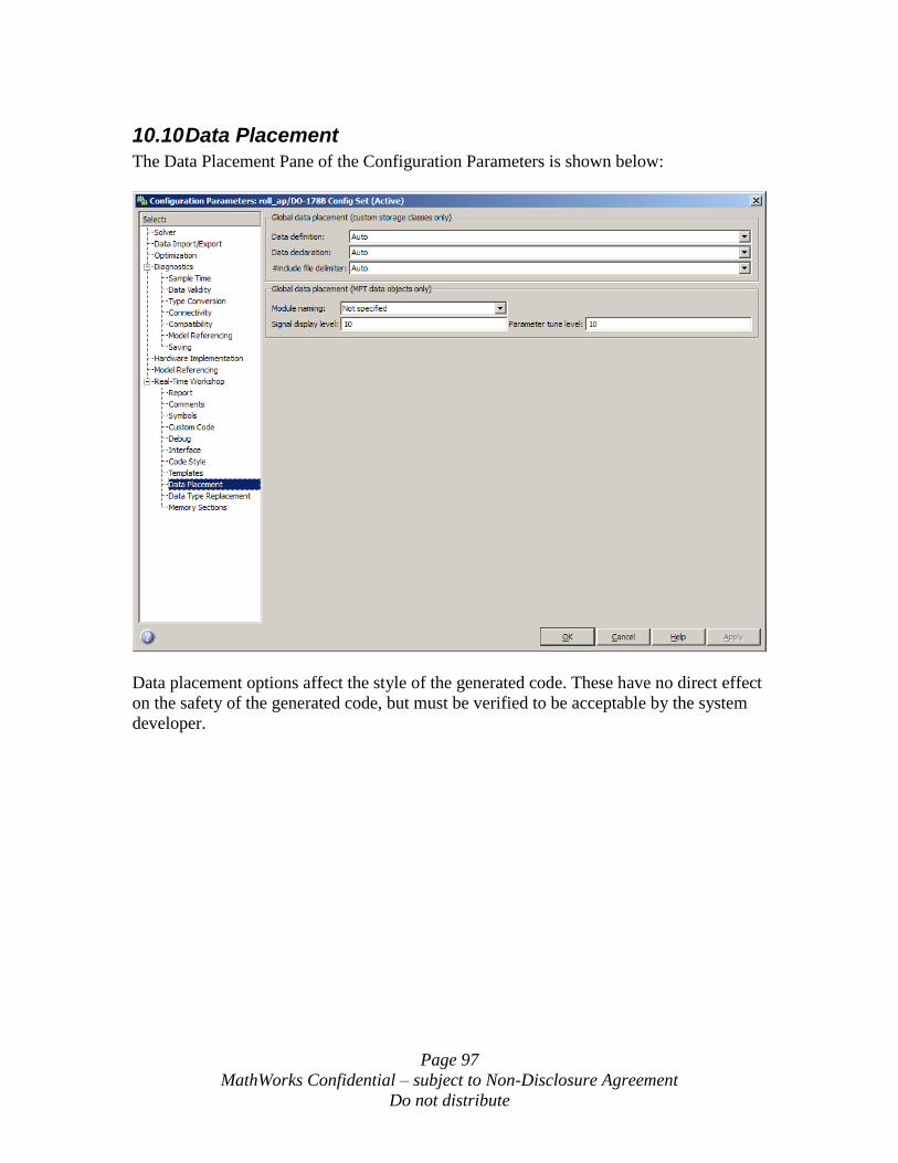
Page 97
MathWorks Confidential – subject to Non-Disclosure Agreement
Do not distribute
10.10 Data Placement
The Data Placement Pane of the Configuration Parameters is shown below:
Data placement options affect the style of the generated code. These have no direct effect
on the safety of the generated code, but must be verified to be acceptable by the system
developer.
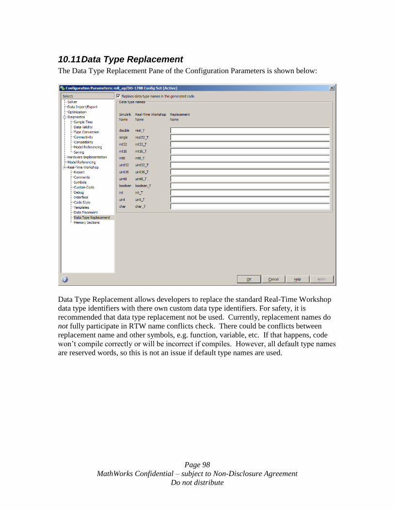
Page 98
MathWorks Confidential – subject to Non-Disclosure Agreement
Do not distribute
10.11 Data Type Replacement
The Data Type Replacement Pane of the Configuration Parameters is shown below:
Data Type Replacement allows developers to replace the standard Real-Time Workshop
data type identifiers with there own custom data type identifiers. For safety, it is
recommended that data type replacement not be used. Currently, replacement names do
not fully participate in RTW name conflicts check. There could be conflicts between
replacement name and other symbols, e.g. function, variable, etc. If that happens, code
won‟t compile correctly or will be incorrect if compiles. However, all default type names
are reserved words, so this is not an issue if default type names are used.
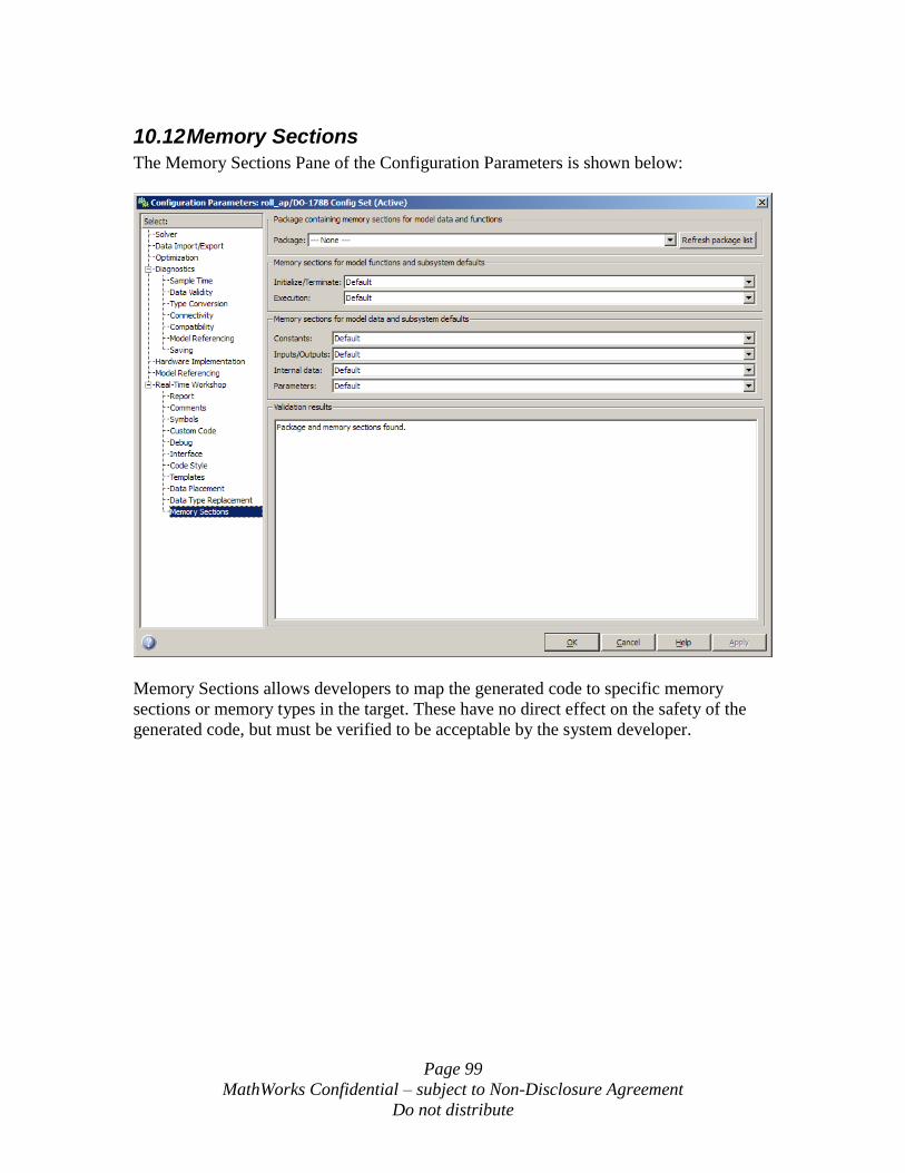
Page 99
MathWorks Confidential – subject to Non-Disclosure Agreement
Do not distribute
10.12 Memory Sections
The Memory Sections Pane of the Configuration Parameters is shown below:
Memory Sections allows developers to map the generated code to specific memory
sections or memory types in the target. These have no direct effect on the safety of the
generated code, but must be verified to be acceptable by the system developer.
Page 100
MathWorks Confidential – subject to Non-Disclosure Agreement
Do not distribute
11 Block Selection Considerations for Safety Critical or Mission Critical Systems
The following sections outline block selection considerations for safety critical or
mission critical systems. This section only considers the basic Simulink Block Library; it
does not address optional block sets or optional embedded targets.
11.1 General Guidelines
Simulink provides a block support table indicating the blocks that are appropriate for
real-time production code. This table can be accessed using the Help -> Block Support
Table menu from a Simulink model. Alternately this can be opened from the Simulink
Block Library by opening the Model Wide Utilities group and then opening Block
Support Table. This table includes caveats and notes that provide guidance on selecting
blocks for code generation.
All blocks marked with note “Not recommended for production code” and “Consider
using the Embedded MATLAB block instead,” must be avoided for real-time safety
critical code. All blocks marked with note “Ignored for code generation” are ignored
during code generation and these blocks should not be included in production code
models, but may be used during debugging of the models or within test harnesses.
All caveats, must be strictly followed when using blocks that have been identified as such.
See section 12 for other block specific considerations for safety critical code generation.
11.2 Specific Blocks of Concern
The following table provides a list of blocks that are acceptable for production code but
are not recommended for safety critical code and the rationale for avoiding these blocks.
Block to Avoid Rationale
Random Number Random number generation may be non-
deterministic and is difficult to verify.
Uniform Random Number Random number generation may be non-
deterministic and is difficult to verify.
Band-Limited White Noise White noise generation may be non-
deterministic and is difficult to verify.
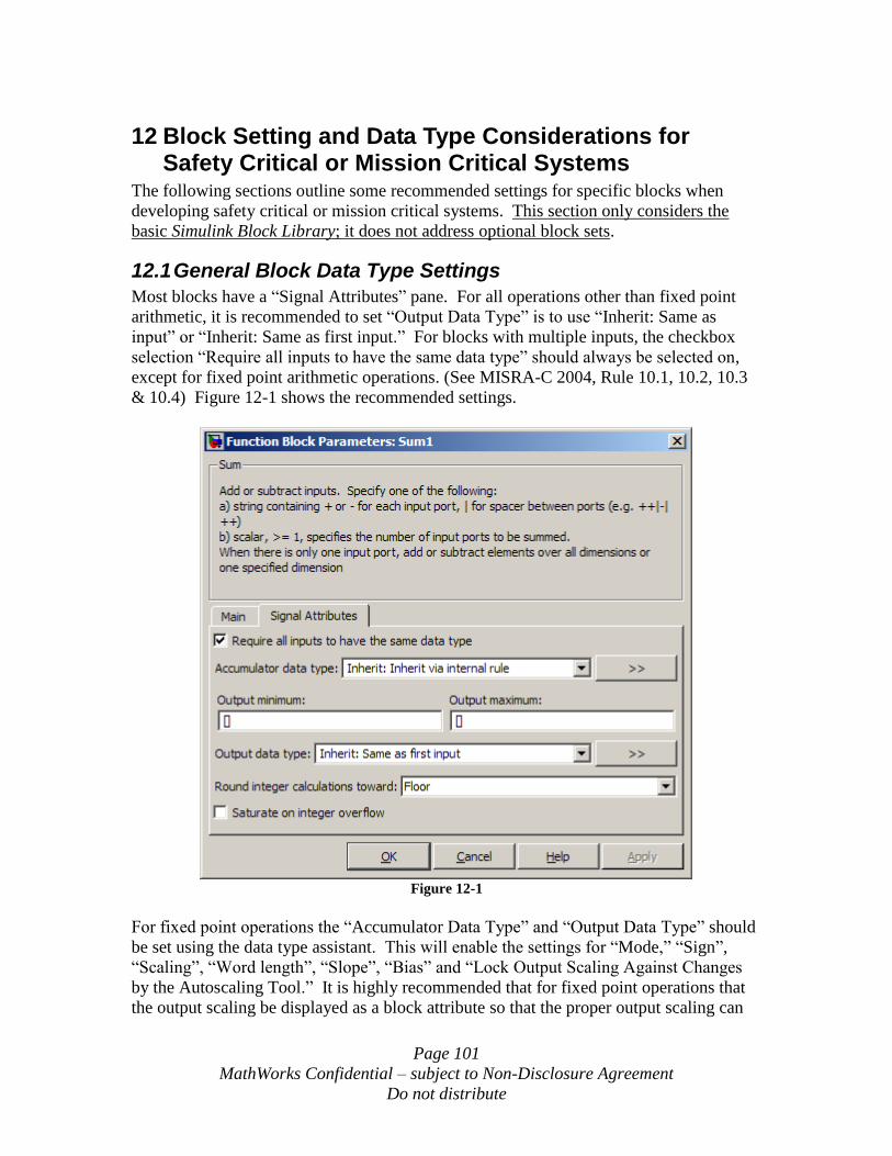
Page 101
MathWorks Confidential – subject to Non-Disclosure Agreement
Do not distribute
12 Block Setting and Data Type Considerations for Safety Critical or Mission Critical Systems
The following sections outline some recommended settings for specific blocks when
developing safety critical or mission critical systems. This section only considers the
basic Simulink Block Library; it does not address optional block sets.
12.1 General Block Data Type Settings
Most blocks have a “Signal Attributes” pane. For all operations other than fixed point
arithmetic, it is recommended to set “Output Data Type” is to use “Inherit: Same as
input” or “Inherit: Same as first input.” For blocks with multiple inputs, the checkbox
selection “Require all inputs to have the same data type” should always be selected on,
except for fixed point arithmetic operations. (See MISRA-C 2004, Rule 10.1, 10.2, 10.3
& 10.4) Figure 12-1 shows the recommended settings.
Figure 12-1
For fixed point operations the “Accumulator Data Type” and “Output Data Type” should
be set using the data type assistant. This will enable the settings for “Mode,” “Sign”,
“Scaling”, “Word length”, “Slope”, “Bias” and “Lock Output Scaling Against Changes
by the Autoscaling Tool.” It is highly recommended that for fixed point operations that
the output scaling be displayed as a block attribute so that the proper output scaling can
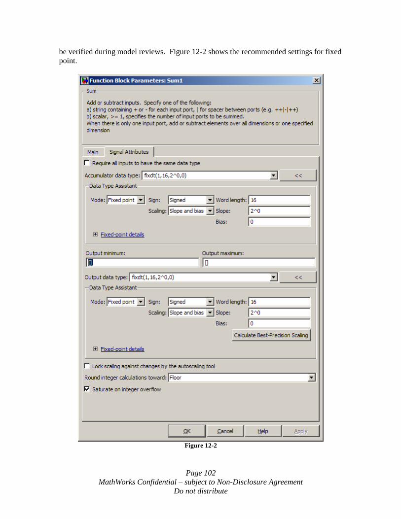
Page 102
MathWorks Confidential – subject to Non-Disclosure Agreement
Do not distribute
be verified during model reviews. Figure 12-2 shows the recommended settings for fixed
point.
Figure 12-2
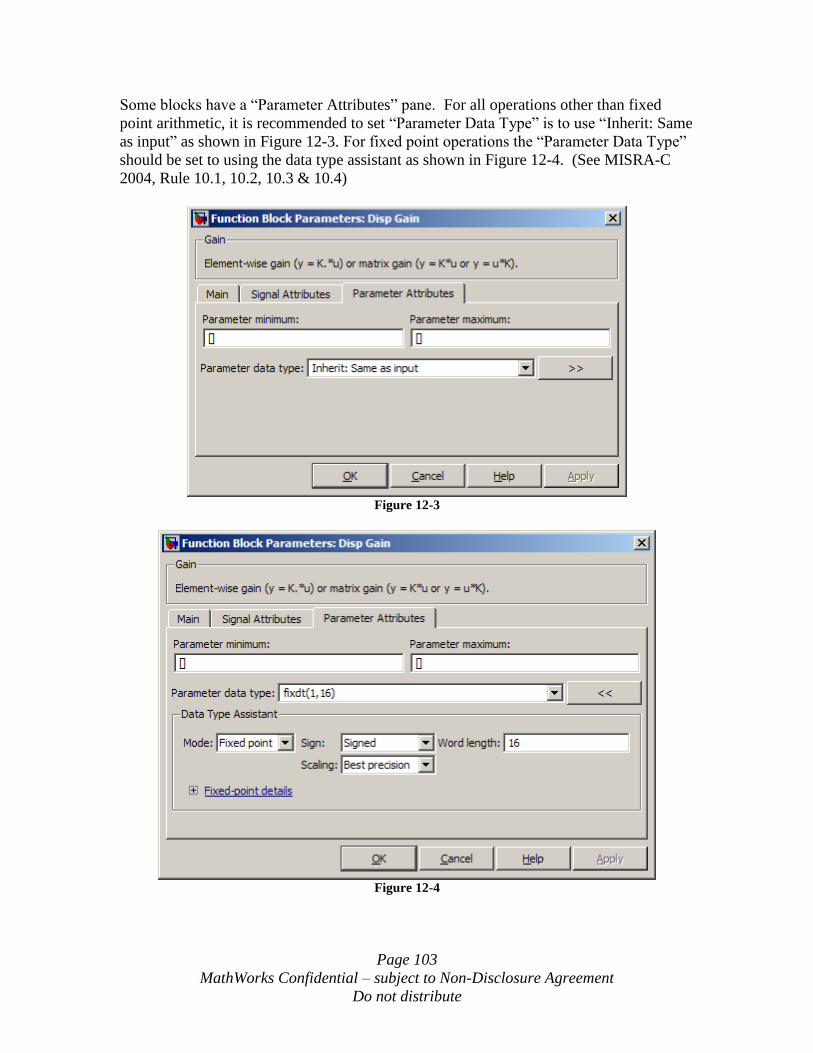
Page 103
MathWorks Confidential – subject to Non-Disclosure Agreement
Do not distribute
Some blocks have a “Parameter Attributes” pane. For all operations other than fixed
point arithmetic, it is recommended to set “Parameter Data Type” is to use “Inherit: Same
as input” as shown in Figure 12-3. For fixed point operations the “Parameter Data Type”
should be set to using the data type assistant as shown in Figure 12-4. (See MISRA-C
2004, Rule 10.1, 10.2, 10.3 & 10.4)
Figure 12-3
Figure 12-4
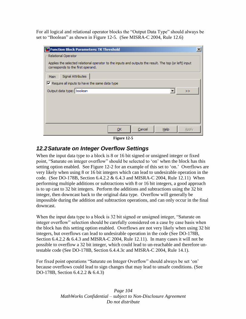
Page 104
MathWorks Confidential – subject to Non-Disclosure Agreement
Do not distribute
For all logical and relational operator blocks the “Output Data Type” should always be
set to “Boolean” as shown in Figure 12-5. (See MISRA-C 2004, Rule 12.6)
Figure 12-5
12.2 Saturate on Integer Overflow Settings
When the input data type to a block is 8 or 16 bit signed or unsigned integer or fixed
point, “Saturate on integer overflow” should be selected to „on‟ when the block has this
setting option enabled. See Figure 12-2 for an example of this set to „on.‟ Overflows are
very likely when using 8 or 16 bit integers which can lead to undesirable operation in the
code. (See DO-178B, Section 6.4.2.2 & 6.4.3 and MISRA-C 2004, Rule 12.11) When
performing multiple additions or subtractions with 8 or 16 bit integers, a good approach
is to up cast to 32 bit integers. Perform the additions and subtractions using the 32 bit
integer, then downcast back to the original data type. Overflow will generally be
impossible during the addition and subtraction operations, and can only occur in the final
downcast.
When the input data type to a block is 32 bit signed or unsigned integer, “Saturate on
integer overflow” selection should be carefully considered on a case by case basis when
the block has this setting option enabled. Overflows are not very likely when using 32 bit
integers, but overflows can lead to undesirable operation in the code (See DO-178B,
Section 6.4.2.2 & 6.4.3 and MISRA-C 2004, Rule 12.11). In many cases it will not be
possible to overflow a 32 bit integer, which could lead to un-reachable and therefore un-
testable code (See DO-178B, Section 6.4.4.3c and MISRA-C 2004, Rule 14.1).
For fixed point operations “Saturate on Integer Overflow” should always be set „on‟
because overflows could lead to sign changes that may lead to unsafe conditions. (See
DO-178B, Section 6.4.2.2 & 6.4.3)
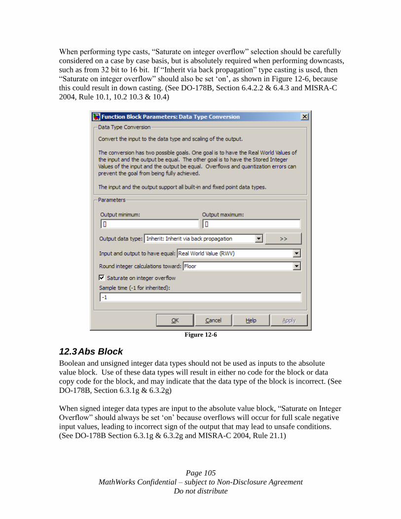
Page 105
MathWorks Confidential – subject to Non-Disclosure Agreement
Do not distribute
When performing type casts, “Saturate on integer overflow” selection should be carefully
considered on a case by case basis, but is absolutely required when performing downcasts,
such as from 32 bit to 16 bit. If “Inherit via back propagation” type casting is used, then
“Saturate on integer overflow” should also be set „on‟, as shown in Figure 12-6, because
this could result in down casting. (See DO-178B, Section 6.4.2.2 & 6.4.3 and MISRA-C
2004, Rule 10.1, 10.2 10.3 & 10.4)
Figure 12-6
12.3 Abs Block
Boolean and unsigned integer data types should not be used as inputs to the absolute
value block. Use of these data types will result in either no code for the block or data
copy code for the block, and may indicate that the data type of the block is incorrect. (See
DO-178B, Section 6.3.1g & 6.3.2g)
When signed integer data types are input to the absolute value block, “Saturate on Integer
Overflow” should always be set „on‟ because overflows will occur for full scale negative
input values, leading to incorrect sign of the output that may lead to unsafe conditions.
(See DO-178B Section 6.3.1g & 6.3.2g and MISRA-C 2004, Rule 21.1)
Page 106
MathWorks Confidential – subject to Non-Disclosure Agreement
Do not distribute
12.4 Data Store Blocks
Use of Data Store blocks can result in unexpected execution order and data behavior
across different sample times or different models. If Data Store blocks are going to be
used in safety critical systems, then the following rules are recommended:
All data store diagnostics should be set to warning or error
Data stores whose reads and writes occur across model and atomic subsystem
boundaries should be avoided when possible because Simulink‟s sorting
algorithm does not take into account data coupling between models and atomic
subsystems due to access of common data stores
Data stores should not be used to write and read data at different rates since this
can result in un-predictable data between the different rates. In order to avoid this ,
rate transition blocks may be used prior to data store writes or after data store
reads to provide deterministic data coupling in multi-rate systems
The use of Data Store blocks can have significant effects on the software verification
effort, especially in the area of data coupling and control. Models and subsystems which
use only inports and outports to pass data result in clean, deterministic and verifiable
interfaces in the generated code. (See DO-178B, Section 6.3.3b)
12.5 For Iterator Subsystem
When using For Iterator subsystems, it is recommended that variable iteration values be
avoided (See DO-178B, Section 6.4.2.2d and MISRA-C 2004, Rule 13.6). The use of
variable for loops can lead to unpredictable execution time and in the case of external
iteration variables, infinite loops may occur.
Methods to avoid variable for loops are:
Set “Iteration Limit Source” to “internal”
If “Iteration Limit Source” is set to “external”, use a Constant, Probe or Width
block as source
Avoid setting “Set Next I (Iteration Variable) Externally”
When using For Iterator subsystems it is recommended that sample time dependent
blocks such as integrators, filters and transfer functions not be used within these
subsystems because they will not function properly with an inherited sample time.
12.6 Inport and Outport Blocks
When using the Inport and Outport blocks at the top level of a model, the following
settings should be explicitly specified, as shown in Figure 12-7, rather than using the
“auto” selection:
Port dimensions
Sample time
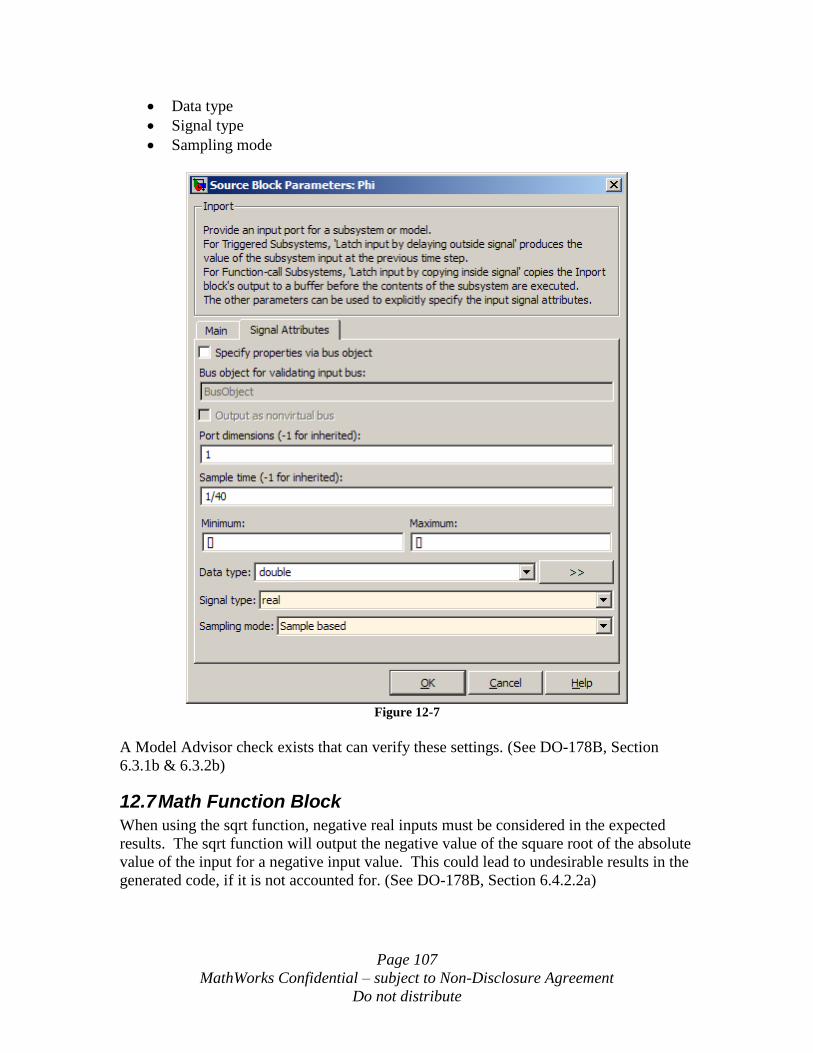
Page 107
MathWorks Confidential – subject to Non-Disclosure Agreement
Do not distribute
Data type
Signal type
Sampling mode
Figure 12-7
A Model Advisor check exists that can verify these settings. (See DO-178B, Section
6.3.1b & 6.3.2b)
12.7 Math Function Block
When using the sqrt function, negative real inputs must be considered in the expected
results. The sqrt function will output the negative value of the square root of the absolute
value of the input for a negative input value. This could lead to undesirable results in the
generated code, if it is not accounted for. (See DO-178B, Section 6.4.2.2a)
Page 108
MathWorks Confidential – subject to Non-Disclosure Agreement
Do not distribute
The math functions log, log10 and rem rely on non-finite number support, which may
result in numeric exceptions in the generated code. It is recommended that these math
functions not be used. (See DO-178B, Section 6.4.2.2 & 6.4.3 and MISRA-C 2004, Rule
21.1) If these functions are necessary in the design then a custom hand coded S-Function
with built-in protection against non-finite numbers may be used in place of these math
functions. For log and log10 functions, if precision is not an issue, then a lookup table
may be used in place of these math functions.
When using the math function reciprocal, it is possible to get a divide by zero, resulting
in inf as an output. When using this function, the divisor input must be protected from
going to zero. (See DO-178B, Section 6.4.2.2 & 6.4.3 and MISRA-C 2004, Rule 21.1)
12.8 Merge Block
The merge block output will be representative of the most recently computed inputs.
This block must be used with great care because the output is dependent upon the
execution order of the input computations. There are two acceptable use cases for the
merge block:
1) Merge two vector signals of different lengths into a single vector whose length is
the sum of the input vectors
2) Merge the outputs of conditionally executed subsystems so that the output of the
merge block represents the last executed subsystem.
When use case 2 is implemented, the conditionally executed subsystems should be set up
to be mutually exclusive in all cases. This is necessary to provide predictable behavior of
the merge block output (See DO-178B, Section 6.3.3b). Methods to insure predictability
are:
1) Use Enabled Subsystem inputs whose enable logic provides exclusive execution
of the subsystems
2) Use Action Subsystem inputs that are all enabled from the same If-Else block
which provides exclusive execution of the subsystems
3) Use Action Subsystem inputs that are all enabled from the same Switch-Case
block which provides exclusive execution of the subsystems
12.9 Product Block
When using the product block with divisor inputs, it is possible to get a divide by zero,
resulting in inf as an output. When using this block, all divisor inputs must be protected
from going to zero. (See DO-178B, Section 6.4.2.2 & 6.4.3 and MISRA-C 2004, Rule
21.1)
When using the product block as a matrix inverse or as a matrix divide, it is possible to
get a divide by a singular matrix, resulting in inf as an output. When using this block, all
divisor inputs must be protected from singular input matrixes. (See DO-178B, Section
6.4.2.2 & 6.4.3 and MISRA-C 2004, Rule 21.1)

Page 109
MathWorks Confidential – subject to Non-Disclosure Agreement
Do not distribute
12.10 Relational Operator Blocks
When any type of relational operator block, including Relational Operator, Compare To
Constant, Compare to Zero and Detect Change blocks, is used on floating point signals,
the “==” and “~=” operators should not be used. Because of floating point precision
issues, the use of these operators on floating point signals is unreliable. (See DO-178B,
Section 6.4.2.2 & 6.4.3 and MISRA-C 2004, Rule 13.3)
12.11 Triggered Subsystem
When using Triggered subsystems it is recommended that sample time dependent blocks
such as filters and transfer functions not be used within these subsystems because they
will not function properly with an inherited sample time.
12.12 While Iterator Subsystem
When using While Iterator subsystems, it is recommended that the number of iterations
be limited (See DO-178B, Section 6.4.3c and MISRA-C 2004, Rule 21.1). The use of
unlimited number of iterations can lead to infinite loops in the real-time code which will
lead to execution time overruns.
In order to avoid potential infinite loops the While Iterator parameter “Maximum Number
of Iterations” should always be set to a positive integer value. Additionally, it is
recommended that the “Show Iteration Number Port” be selected and that the iteration
value be observed during simulation to determine if the maximum number of iterations is
being reached. In cases where the maximum number of iterations is reached, the output
values of the While Iterator Subsystem should be verified to be correct.
When using While Iterator subsystems it is recommended that sample time dependent
blocks such as filters and transfer functions not be used within these subsystems because
they will not function properly with an inherited sample time.
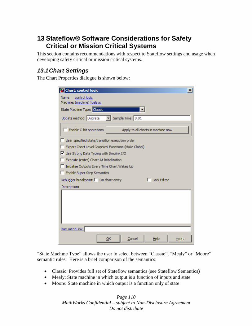
Page 110
MathWorks Confidential – subject to Non-Disclosure Agreement
Do not distribute
13 Stateflow® Software Considerations for Safety Critical or Mission Critical Systems
This section contains recommendations with respect to Stateflow settings and usage when
developing safety critical or mission critical systems.
13.1 Chart Settings
The Chart Properties dialogue is shown below:
“State Machine Type” allows the user to select between “Classic”, “Mealy” or “Moore”
semantic rules. Here is a brief comparison of the semantics:
Classic: Provides full set of Stateflow semantics (see Stateflow Semantics)
Mealy: State machine in which output is a function of inputs and state
Moore: State machine in which output is a function only of state
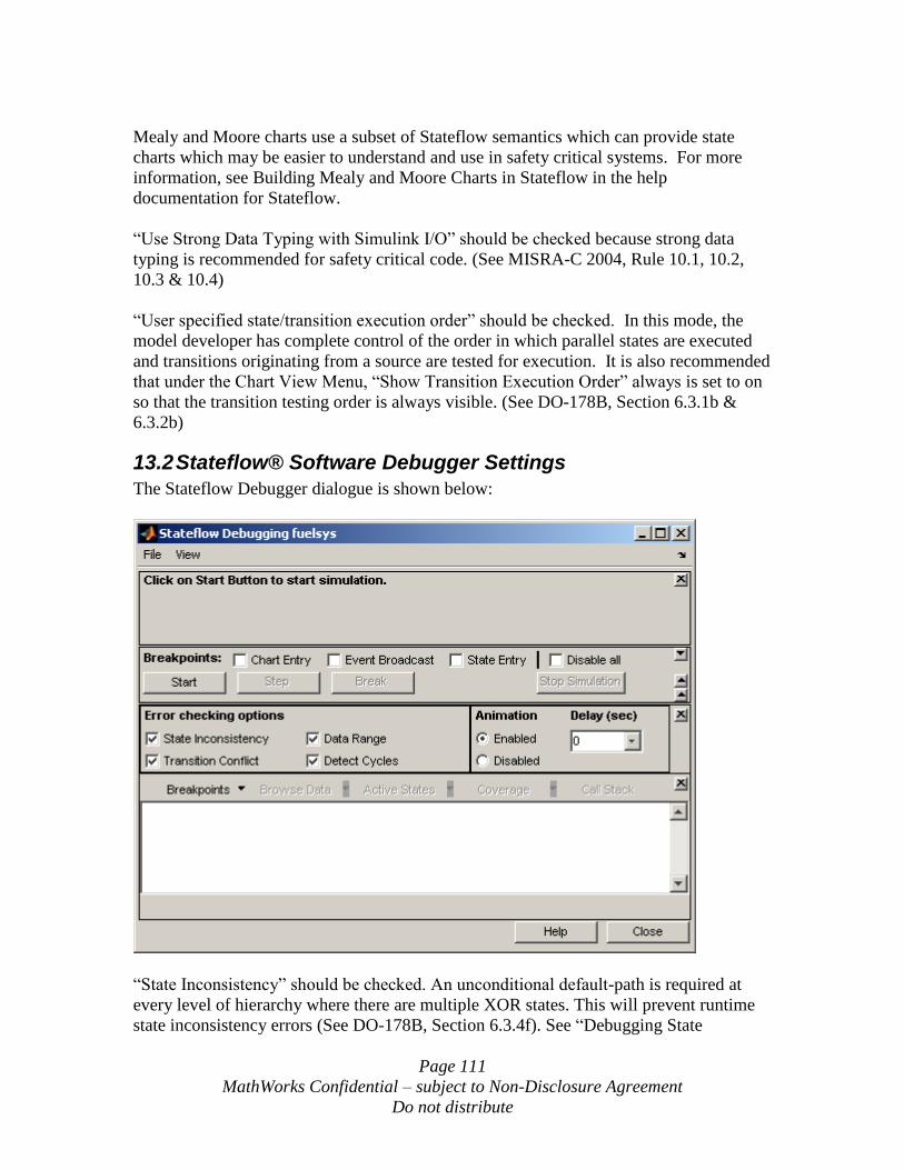
Page 111
MathWorks Confidential – subject to Non-Disclosure Agreement
Do not distribute
Mealy and Moore charts use a subset of Stateflow semantics which can provide state
charts which may be easier to understand and use in safety critical systems. For more
information, see Building Mealy and Moore Charts in Stateflow in the help
documentation for Stateflow.
“Use Strong Data Typing with Simulink I/O” should be checked because strong data
typing is recommended for safety critical code. (See MISRA-C 2004, Rule 10.1, 10.2,
10.3 & 10.4)
“User specified state/transition execution order” should be checked. In this mode, the
model developer has complete control of the order in which parallel states are executed
and transitions originating from a source are tested for execution. It is also recommended
that under the Chart View Menu, “Show Transition Execution Order” always is set to on
so that the transition testing order is always visible. (See DO-178B, Section 6.3.1b &
6.3.2b)
13.2 Stateflow® Software Debugger Settings
The Stateflow Debugger dialogue is shown below:
“State Inconsistency” should be checked. An unconditional default-path is required at
every level of hierarchy where there are multiple XOR states. This will prevent runtime
state inconsistency errors (See DO-178B, Section 6.3.4f). See “Debugging State
Page 112
MathWorks Confidential – subject to Non-Disclosure Agreement
Do not distribute
Inconsistencies” in the Stateflow Help Documentation for a complete description and
example.
“Transition Conflict” should be checked. It checks whether there are two equally valid
transition paths from the same source at any step in the simulation. See “Debugging
Conflicting Transitions” in the Stateflow Help Documentation for a complete description
and example. Charts with conflicting transitions will result in unreachable, and therefore
un-testable, code. (See DO-178B, Section 6.4.4.3c and MISRA-C 2004, Rule 14.1)
“Data Range” should be checked. It checks whether the minimum and maximum values
you specified for a data in its properties dialog are exceeded. It also checks whether
fixed-point data overflows its base word size. See “Debugging Data Range Violations” in
the Stateflow Help Documentation for a complete description and example. Numeric
overflows can result in incorrect and unsafe behavior. (See DO-178B, Section 6.4.2.2 &
6.4.3)
“Detect Cycles” should be checked. It checks whether a step or sequence of steps
indefinitely repeats itself due to a recursive event broadcast. See “Debugging Cyclic
Behavior” in the Stateflow Help Documentation for a complete description and example.
Recursion can lead to unpredictable execution time and also may result in stack
overflows. (See DO-178B, Section 6.3.4f and MISRA-C 2004, Rule 16.2)
13.3 Truth Table Settings
Each Truth Table has settings for Under-specified and Over-specified. Both of these
settings should be set to Error for all truth tables. An over-specified truth table contains a
decision that will never be executed because it is already specified in a previous decision
in the Condition Table. Over-specified truth tables will result in unreachable, and
therefore un-testable, code (See DO-178B, Section 6.4.4.3c and MISRA-C 2004, Rule
14.1). An underspecified truth table lacks one or more possible decisions that might
require an action to avoid undefined behavior in the application (See DO-178B, Section
6.3.4f).
13.4 Chart Commenting
Unlike Simulink blocks in a diagram, Stateflow components are not all uniquely named.
This can lead to difficulty in tracing the code back to the block diagram. To enhance
traceability it is recommended that all states, transitions and truth tables contain uniquely
identifiable comments. These comments will then be inserted into the generated code,
thus providing traceability back to the model. These comments can be added manually to
the charts, or it is also possible to build a script that would add a uniquely identifiable
trace tag to each component of concern. (See DO-178B, Section 6.3.4e)
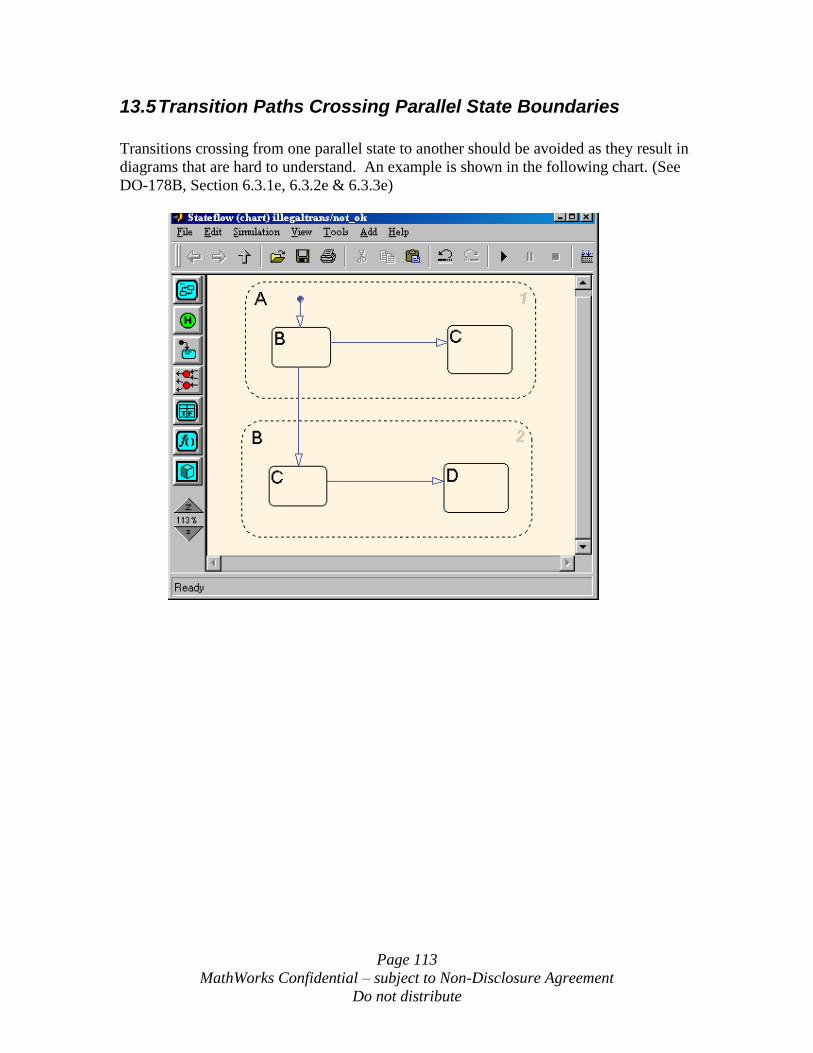
Page 113
MathWorks Confidential – subject to Non-Disclosure Agreement
Do not distribute
13.5 Transition Paths Crossing Parallel State Boundaries
Transitions crossing from one parallel state to another should be avoided as they result in
diagrams that are hard to understand. An example is shown in the following chart. (See
DO-178B, Section 6.3.1e, 6.3.2e & 6.3.3e)
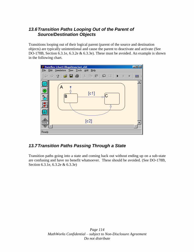
Page 114
MathWorks Confidential – subject to Non-Disclosure Agreement
Do not distribute
13.6 Transition Paths Looping Out of the Parent of Source/Destination Objects
Transitions looping out of their logical parent (parent of the source and destination
objects) are typically unintentional and cause the parent to deactivate and activate (See
DO-178B, Section 6.3.1e, 6.3.2e & 6.3.3e). These must be avoided. An example is shown
in the following chart.
13.7 Transition Paths Passing Through a State
Transition paths going into a state and coming back out without ending up on a sub-state
are confusing and have no benefit whatsoever. These should be avoided. (See DO-178B,
Section 6.3.1e, 6.3.2e & 6.3.3e)
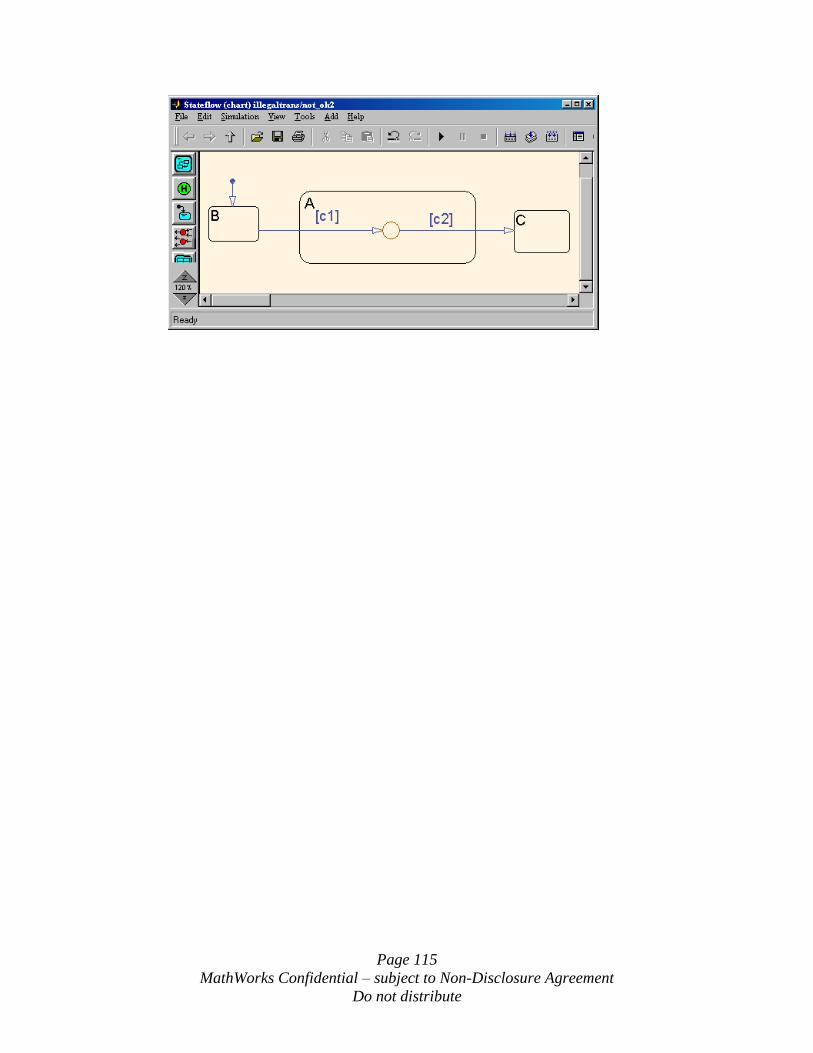
Page 115
MathWorks Confidential – subject to Non-Disclosure Agreement
Do not distribute
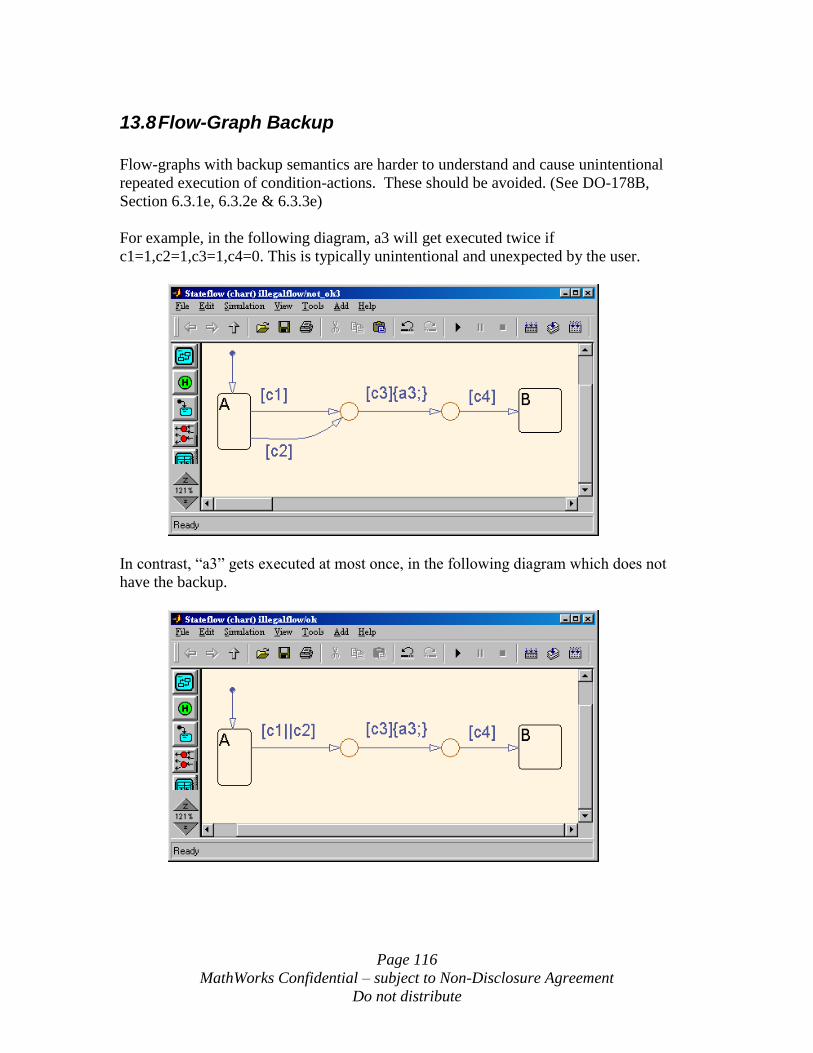
Page 116
MathWorks Confidential – subject to Non-Disclosure Agreement
Do not distribute
13.8 Flow-Graph Backup
Flow-graphs with backup semantics are harder to understand and cause unintentional
repeated execution of condition-actions. These should be avoided. (See DO-178B,
Section 6.3.1e, 6.3.2e & 6.3.3e)
For example, in the following diagram, a3 will get executed twice if
c1=1,c2=1,c3=1,c4=0. This is typically unintentional and unexpected by the user.
In contrast, “a3” gets executed at most once, in the following diagram which does not
have the backup.
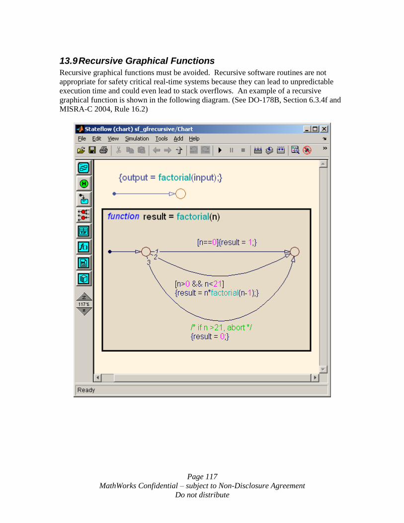
Page 117
MathWorks Confidential – subject to Non-Disclosure Agreement
Do not distribute
13.9 Recursive Graphical Functions
Recursive graphical functions must be avoided. Recursive software routines are not
appropriate for safety critical real-time systems because they can lead to unpredictable
execution time and could even lead to stack overflows. An example of a recursive
graphical function is shown in the following diagram. (See DO-178B, Section 6.3.4f and
MISRA-C 2004, Rule 16.2)
Page 118
MathWorks Confidential – subject to Non-Disclosure Agreement
Do not distribute
14 Run-Time Library Considerations for Safety Critical or Mission Critical Systems
This section contains recommendations with respect to runtime library usage when
developing safety critical or mission critical systems. Real-Time Workshop Embedded
Coder generates code that calls custom runtime library code. All runtime libraries are
auto-generated as needed. These runtime libraries are used for various functions that are
not supplied with standard ANSI-C, ISO-C or GNU runtime libraries.
14.1 Runtime Libraries
All of the runtime libraries get auto-generated by Real-Time Workshop Embedded Coder
on an “as needed” basis. The location of the generated files can be controlled from the
Interface Pane of the Configuration Parameters Dialog. Various header and code files for
the library functions may be generated. Some of these libraries may be in the form of
function macros, and others may be in the form of C functions.
When using model reference, these functions will be put into a shared directory (see
Real-Time Workshop documentation for details) for use by all model generated code. If
Real-Time Workshop detects that a particular library function already exists in the shared
location, it will not generate that function again.
All function macros should be verified when testing the auto-generated code that uses
each of the macros. Functions implemented as code may be tested and verified
independently of the individual usage of the functions in the code generated for the
models.
14.2 MISRA-C Violations
The use of function like macros, which are used by Real-Time Workshop Embedded
Coder, is a violation of a MISRA Advisory Rule. MISRA-C 2004, Rule 19.7, advises
against the use of function like macros and recommends functions instead. However, this
is not a mandatory rule.
For release R2008b, not all of the runtime library functions are MISRA-C compliant. If
MISRA-C is to be used for the coding standards for a Model-Based Design process, then
modifications to some of these files may be required to bring the runtime libraries into
compliance with MISRA-C rules that are selected for the application. The violation of
advisory rule 19.7 is an example of non-compliance for the runtime libraries. This does
not represent all of the possible MISRA-C violations.
To request MISRA-C compliance information for Real-Time Workshop Embedded
Coder, use the following link:

Page 119
MathWorks Confidential – subject to Non-Disclosure Agreement
Do not distribute
http://www.mathworks.com/support/solutions/data/1-1IFP0W.html

Page 120
MathWorks Confidential – subject to Non-Disclosure Agreement
Do not distribute
This page left blank intentionally.