Embed Size (px)
Citation preview
450 Riverside Dr • Wyalusing PA, 18853 • Phone 570-746-1888 • Fax 570-746-9286
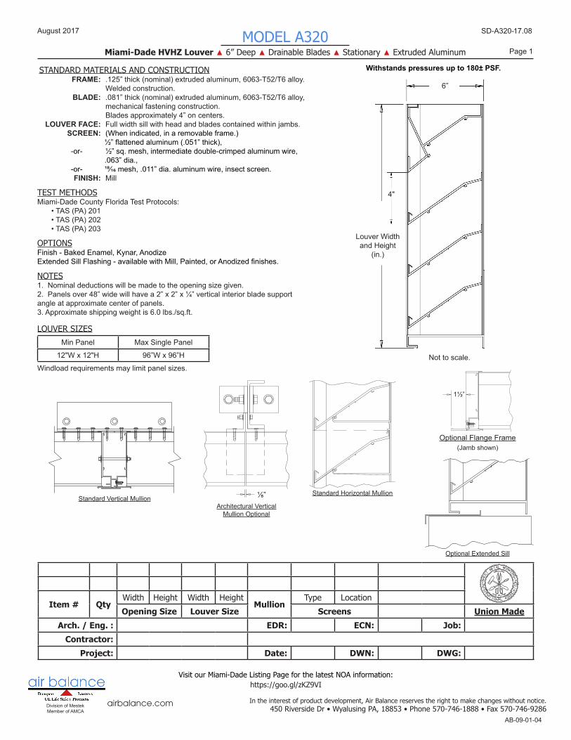
Page 1MODEL A320
Miami-Dade HVHZ Louver ▲ 6” Deep ▲ Drainable Blades ▲ Stationary ▲ Extruded Aluminum
Division of Mestek Member of AMCA
airbalance.com
SD-A320-17.08
AB-09-01-04
August 2017
STANDARD MATERIALS AND CONSTRUCTION
OPTIONS
NOTES
TEST METHODS
In the interest of product development, Air Balance reserves the right to make changes without notice.
LOUVER SIZES
Item # QtyWidth Height Width Height
MullionType Location
Opening Size Louver Size Screens Union MadeArch. / Eng. : EDR: ECN: Job:
Contractor: Project: Date: DWN: DWG:
Min Panel Max Single Panel
12"W x 12"H 96”W x 96”H
FRAME: .125” thick (nominal) extruded aluminum, 6063-T52/T6 alloy. Welded construction. BLADE: .081” thick (nominal) extruded aluminum, 6063-T52/T6 alloy, mechanical fastening construction. Blades approximately 4” on centers. LOUVER FACE: Full width sill with head and blades contained within jambs. SCREEN: (When indicated, in a removable frame.) ½”flattenedaluminum(.051”thick), -or- ½” sq. mesh, intermediate double-crimped aluminum wire, .063” dia., -or- ¹⁸⁄16 mesh, .011” dia. aluminum wire, insect screen. FINISH: Mill
Miami-Dade County Florida Test Protocols: • TAS (PA) 201 • TAS (PA) 202 • TAS (PA) 203
Finish - Baked Enamel, Kynar, AnodizeExtendedSillFlashing-availablewithMill,Painted,orAnodizedfinishes.
1. Nominal deductions will be made to the opening size given.2. Panels over 48” wide will have a 2” x 2” x ¼” vertical interior blade support angle at approximate center of panels.3. Approximate shipping weight is 6.0 lbs./sq.ft.
Windload requirements may limit panel sizes.
Withstands pressures up to 180± PSF.
Visit our Miami-Dade Listing Page for the latest NOA information:https://goo.gl/zKZ9VI
⅛”Architectural Vertical
Mullion Optional
Standard Horizontal MullionStandard Vertical Mullion
6”
Louver Widthand Height
(in.)
Not to scale.
4"
Optional Flange Frame
1½”
(Jamb shown)
Optional Extended Sill
450 Riverside Dr • Wyalusing PA, 18853 • Phone 570-746-1888 • Fax 570-746-9286
Page 2MODEL A320
Miami-Dade HVHZ Louver ▲ 6” Deep ▲ Drainable Blades ▲ Stationary ▲ Extruded Aluminum
Division of Mestek Member of AMCA
airbalance.com
SD-A320-17.08
AB-09-01-04
August 2017
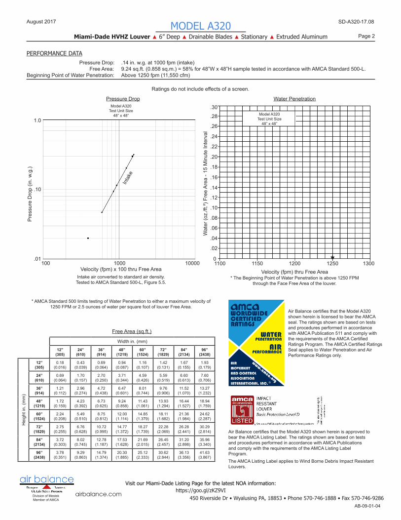
PERFORMANCE DATA
Width in. (mm)
12"(305)
24”(610)
36”(914)
48”(1219)
60”(1524)
72”(1829)
84”(2134)
96”(2438)
Hei
ght i
n. (m
m)
12”(305)
0.18(0.016)
0.43(0.039)
0.69(0.064)
0.94(0.087)
1.16(0.107)
1.42(0.131)
1.67(0.155)
1.93(0.179)
24”(610)
0.69(0.064)
1.70(0.157)
2.70(0.250)
3.71(0.344)
4.59(0.426)
5.59(0.519)
6.60(0.613)
7.60(0.706)
36”(914)
1.21(0.112)
2.96(0.274)
4.72(0.438)
6.47(0.601)
8.01(0.744)
9.76(0.906)
11.52(1.070)
13.27(1.232)
48”(1219)
1.72(0.159)
4.23(0.392)
6.73(0.625)
9.24(0.858)
11.43(1.061)
13.93(1.294)
16.44(1.527)
18.94(1.759)
60”(1524)
2.24(0.208)
5.49(0.510)
8.75(0.812)
12.00(1.114)
14.85(1.379)
18.11(1.682)
21.36(1.984)
24.62(2.287)
72”(1829)
2.75(0.255)
6.76(0.628)
10.72(0.995)
14.77(1.372)
18.27(1.739)
22.28(2.069)
26.28(2.441)
30.29(2.814)
84”(2134)
3.72(0.303)
8.02(0.745)
12.78(1.187)
17.53(1.628)
21.69(2.015)
26.45(2.457)
31.20(2.898)
35.96(3.340)
96”(2438)
3.78(0.351)
9.29(0.863)
14.79(1.374)
20.30(1.885)
25.12(2.333)
30.62(2.844)
36.13(3.356)
41.63(3.867)
Free Area (sq.ft.)
AirBalancecertifiesthattheModelA320shown herein is licensed to bear the AMCA seal. The ratings shown are based on tests and procedures performed in accordance with AMCA Publication 511 and comply with therequirementsoftheAMCACertifiedRatingsProgram.TheAMCACertifiedRatingsSeal applies to Water Penetration and Air Performance Ratings only.
AirBalancecertifiesthattheModelA320shownhereinisapprovedtobear the AMCA Listing Label. The ratings shown are based on tests and procedures performed in accordance with AMCA Publications and comply with the requirements of the AMCA Listing Label Program.The AMCA Listing Label applies to Wind Borne Debris Impact Resistant Louvers.
Pressure Drop: .14 in. w.g. at 1000 fpm (intake) Free Area: 9.24 sq.ft. (0.858 sq.m.) = 58% for 48”W x 48”H sample tested in accordance with AMCA Standard 500-L.Beginning Point of Water Penetration: Above 1250 fpm (11,550 cfm)
Visit our Miami-Dade Listing Page for the latest NOA information:https://goo.gl/zKZ9VI
Ratingsdonotincludeeffectsofascreen.
Pres
sure
Dro
p (in
. w.g
.)
Pressure Drop
Velocity (fpm) x 100 thru Free Area100 1000 10000
.01
.10
1.0In
take
Intake air converted to standard air density. Tested to AMCA Standard 500-L, Figure 5.5.
Model A320Test Unit Size
48” x 48”
* AMCA Standard 500 limits testing of Water Penetration to either a maximum velocity of 1250 FPM or 2.5 ounces of water per square foot of louver Free Area.
115011000
.02
.04
.06
.08
.10
.12
.14
.16
.18
.20
.22
.24
.26
.28
.30
Velocity (fpm) thru Free Area
Water Penetration
12501200 1300
* The Beginning Point of Water Penetration is above 1250 FPM through the Face Free Area of the louver.
Wat
er (o
z./ft
.²) F
ree
Area
- 15
Min
ute
Inte
rval
*
Model A320Test Unit Size
48” x 48”
450 Riverside Dr • Wyalusing PA, 18853 • Phone 570-746-1888 • Fax 570-746-9286
Page 3MODEL A320
Miami-Dade HVHZ Louver ▲ 6” Deep ▲ Drainable Blades ▲ Stationary ▲ Extruded Aluminum
Division of Mestek Member of AMCA
airbalance.com
SD-A320-17.08
AB-09-01-04
August 2017
Visit our Miami-Dade Listing Page for the latest NOA information:https://goo.gl/zKZ9VI
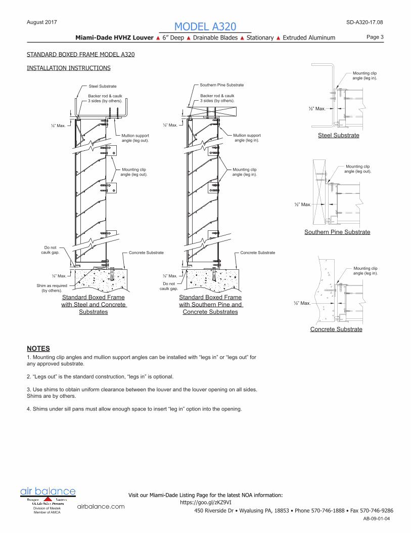
Backer rod & caulk 3 sides (by others).
Do not caulk gap.
Mullion support angle (leg out).
Mounting clip angle (leg out).
Shim as required(by others).
Steel Substrate
Concrete Substrate
½” Max.
½” Max.
Standard Boxed Framewith Steel and Concrete
Substrates
Backer rod & caulk 3 sides (by others).
Do not caulk gap.
Mullion support angle (leg in).
Mounting clip angle (leg in).
Southern Pine Substrate
Concrete Substrate
½” Max.
½” Max.
Standard Boxed Framewith Southern Pine and
Concrete Substrates
Mounting clip angle (leg in).
½” Max.
Steel Substrate
Mounting clip angle (leg in).
½” Max.
Concrete Substrate
Mounting clip angle (leg out).
½” Max.
Southern Pine Substrate
STANDARD BOXED FRAME MODEL A320
INSTALLATION INSTRUCTIONS
NOTES1. Mounting clip angles and mullion support angles can be installed with “legs in” or “legs out” for any approved substrate.
2. “Legs out” is the standard construction, “legs in” is optional.
3. Use shims to obtain uniform clearance between the louver and the louver opening on all sides. Shims are by others.
4. Shims under sill pans must allow enough space to insert “leg in” option into the opening.
450 Riverside Dr • Wyalusing PA, 18853 • Phone 570-746-1888 • Fax 570-746-9286
Page 4MODEL A320
Miami-Dade HVHZ Louver ▲ 6” Deep ▲ Drainable Blades ▲ Stationary ▲ Extruded Aluminum
Division of Mestek Member of AMCA
airbalance.com
SD-A320-17.08
AB-09-01-04
August 2017
Visit our Miami-Dade Listing Page for the latest NOA information:https://goo.gl/zKZ9VI
Backer rod & caulk 3 sides (by others).
Mullion support angle (leg out).
Mounting clip angle (leg out).
Steel Substrate
½” Max. (Typ.)
¼” Max.
Flanged Sleeve Framewith Steel and Concrete
Substrates
Mounting clip angle (leg in).
¼” Max.
½” Max.
Steel Substrate
Mounting clip angle (leg in).
¼” Max.
½” Max.
Concrete Substrate
Mounting clip angle (leg out).
¼” Max.
½” Max.
Southern Pine Substrate
FLANGED SLEEVE MODEL A320
INSTALLATION INSTRUCTIONS
NOTES1. Mounting clip angles and mullion support angles can be installed with “legs in” or “legs out” for any approved substrate.
2. “Legs out” is the standard construction, “legs in” is optional.
3.Theflangedsleevecanbeusedwithanyapprovedsubstrate.
4. Use shims to obtain uniform clearance between the louver and the louver opening on all sides. Shims are by others.
5.Sealant/caulkbetweenflangedanglesleeveandsubtrate(typ.4sides)byinstaller.
6. Two mounting angles run the full height and length of louver.
Do not caulk gap.
Mullion support angle (leg in).
Mounting clip angle (leg in).
See Note 5.
Southern Pine Substrate
Concrete Substrate
½” Max. (Typ.)
¼” Max.
¼” Max.
Flanged Sleeve Framewith Southern Pine and
Concrete Substrates
Backer rod & caulk 3 sides (by others).
Do not caulk gap.
See Note 5.
Concrete Substrate
¼” Max.
450 Riverside Dr • Wyalusing PA, 18853 • Phone 570-746-1888 • Fax 570-746-9286
Page 5MODEL A320
Miami-Dade HVHZ Louver ▲ 6” Deep ▲ Drainable Blades ▲ Stationary ▲ Extruded Aluminum
Division of Mestek Member of AMCA
airbalance.com
SD-A320-17.08
AB-09-01-04
August 2017
Visit our Miami-Dade Listing Page for the latest NOA information:https://goo.gl/zKZ9VI
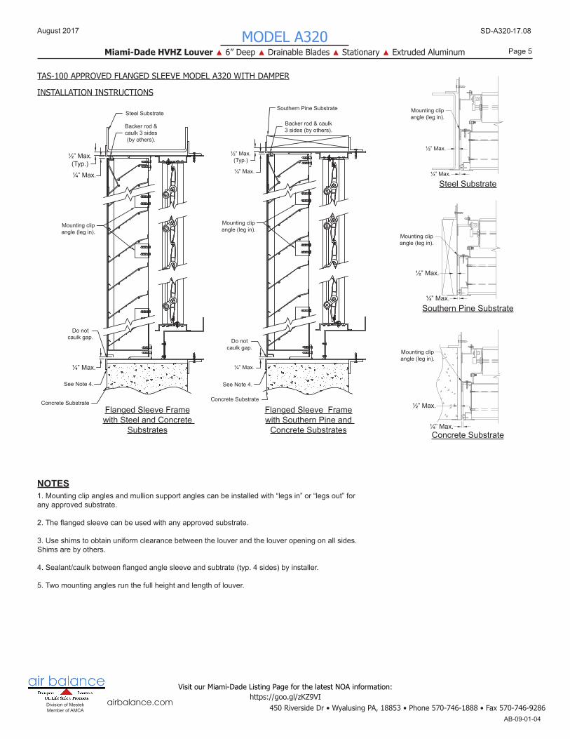
Backer rod & caulk 3 sides (by others).
Mounting clip angle (leg in).
Steel Substrate
½” Max. (Typ.)
¼” Max.
Flanged Sleeve Framewith Steel and Concrete
Substrates
Mounting clip angle (leg in).
¼” Max.
½” Max.
Steel Substrate
Mounting clip angle (leg in).
¼” Max.
½” Max.
Concrete Substrate
Mounting clip angle (leg in).
¼” Max.
½” Max.
Southern Pine Substrate
TAS-100 APPROVED FLANGED SLEEVE MODEL A320 WITH DAMPER
INSTALLATION INSTRUCTIONS
NOTES1. Mounting clip angles and mullion support angles can be installed with “legs in” or “legs out” for any approved substrate.
2.Theflangedsleevecanbeusedwithanyapprovedsubstrate.
3. Use shims to obtain uniform clearance between the louver and the louver opening on all sides. Shims are by others.
4.Sealant/caulkbetweenflangedanglesleeveandsubtrate(typ.4sides)byinstaller.
5. Two mounting angles run the full height and length of louver.
Do not caulk gap.
Mounting clip angle (leg in).
See Note 4.
Southern Pine Substrate
Concrete Substrate
½” Max. (Typ.)
¼” Max.
¼” Max.
Flanged Sleeve Framewith Southern Pine and
Concrete Substrates
Backer rod & caulk 3 sides (by others).
Do not caulk gap.
See Note 4.
Concrete Substrate
¼” Max.