Embed Size (px)
Citation preview
Installation, and Maintenance Manual IMM WGZC
Group: Chiller
Part Number: 331975201
Effective: May 2011
Supercedes: October 2010
Water-Cooled Scroll Compressor Chillers
WGZ 030CW to WGZ 200CW, Packaged Water-Cooled Chiller
WGZ 030CA to WGZ 200CA, Chiller with Remote Condenser
30 to 200 Tons, 105 to 700 kW 60 Hz, R-410A
2 WGZ 030C through 200C IMM WGZC
Table of Contents
Introduction ....................................... 3 Nomenclature ........................................ 3
Installation ......................................... 4 Vibration Isolators................................. 6
Limitations of Operation ................ 11
Water Piping .................................... 12 Flow Switch ........................................ 15 Glycol Solutions.................................. 15 Condenser Water Piping...................... 17
Pressure Drops ................................. 17
Refrigerant Piping........................... 20 Unit with Remote Condenser.............. 20 Factory-Mounted Condenser............... 25
Dimensions ....................................... 26 Packaged Chillers................................ 26 Chillers with Remote Condenser ........ 29
Physical Data.................................... 32 Packaged Chillers................................ 32 Chillers with Remote Condenser ........ 35 Operating Limits ................................. 36 Components ........................................ 37
Wiring............................................... 38
Unit Configuration .......................... 39
Electrical Data ................................. 40
Electrical Notes................................... 53 Field Wiring Diagram ......................... 55 Control Panel Layout .......................... 57 Motor Protection Module.................... 57
Start-Up and Shutdown.................. 58 Pre Start-up ......................................... 58 Start-up................................................ 58 Weekend or Temporary Shutdown...... 59 Start-up after Temporary Shutdown.... 59 Extended Shutdown ............................ 59 Start-up after Extended Shutdown ...... 60
System Maintenance ....................... 61 General ................................................ 61 Electrical Terminals ............................ 62 Compressor Lubrication...................... 62 Sightglass and Moisture Indicator ...... 62 Crankcase Heaters............................... 63 Optional Controls................................ 63 Phase/Voltage Monitor (Optional) ...... 63 Hot Gas Bypass (Optional) ................. 64
Maintenance Schedule .................... 65
System Service ................................. 66 Troubleshooting Chart ........................ 68
Warranty Statement........................ 69
Manufactured in an ISO Certified facility
Cover Picture: WGZ 200C, Nominal 200 ton chiller
©2009 McQuay International. Illustrations and data cover the McQuay International product at the time of publication and we reserve the right to
make changes in design and construction at anytime without notice. ™® The following are trademarks or registered trademarks of their respective
companies: BACnet from ASHRAE; LONMARK, LonTalk, LONWORKS, and the LONMARK logo are managed, granted and used by LONMARK
International under a license granted by Echelon Corporation; Compliant Scroll from Copeland Corporation; ElectroFin from AST ElectroFin Inc.;
Modbus from Schneider Electric; FanTrol, MicroTech II, Open Choices, and SpeedTrol from McQuay International
IMM WGZC WGZ 030C through 200C 3
Introduction
General Description
McQuay Type WGZ water chillers are designed for indoor installations and are available with
water-cooled condensers (Model WGZ-CW), or arranged for use with remote, air-cooled or
evaporative condensers (Model WGZ-CA). Each water-cooled unit is completely assembled and
factory wired before evacuation, charging and testing. They consist of hermetic scroll
compressors, brazed-plate evaporators on Models WGZ 030 to 130( shell-and-tube on Models
WGZ 150 to 200), water-cooled condenser (WGZ-CW), and complete refrigerant piping.
Units manufactured for use with remote condensers (Models WGZ-CA) have all refrigerant
specialties factory-mounted and connection points for refrigerant discharge and liquid lines.
Liquid line components that are included are manual liquid line shutoff valves, charging valves,
filter-driers, liquid line solenoid valves, sight glass/moisture indicators, and expansion valves.
Other features include compressor crankcase heaters, and a MicroTech II microprocessor
controller.
The electrical control center includes all equipment protection and operating controls necessary
for dependable automatic operation.
The compressors are not fused as standard, but can be protected by optional circuit breakers or
fuses, or can rely on a field-installed, fused disconnect switch for protection.
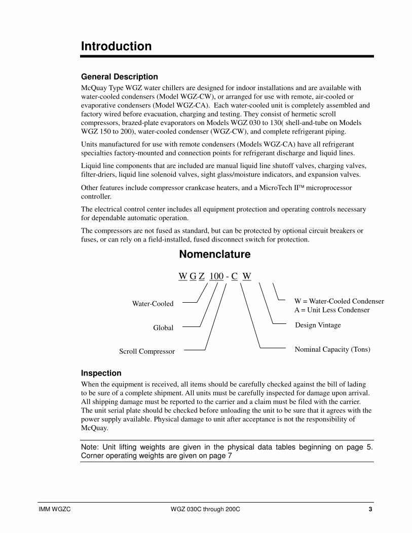
Nomenclature
W G Z 100 - C W
Inspection
When the equipment is received, all items should be carefully checked against the bill of lading
to be sure of a complete shipment. All units must be carefully inspected for damage upon arrival.
All shipping damage must be reported to the carrier and a claim must be filed with the carrier.
The unit serial plate should be checked before unloading the unit to be sure that it agrees with the
power supply available. Physical damage to unit after acceptance is not the responsibility of
McQuay.
Note: Unit lifting weights are given in the physical data tables beginning on page 5. Corner operating weights are given on page 7
Water-Cooled
Global
Scroll Compressor Nominal Capacity (Tons)
W = Water-Cooled Condenser
A = Unit Less Condenser
Design Vintage
4 WGZ 030C through 200C IMM WGZC
Installation
Note: Installation and maintenance are to be performed only by qualified personnel who are familiar with local codes and regulations, and experienced with this type of equipment.
! WARNING
Avoid contact with sharp edges. Personal injury can result
Handling
Every model WGZ-CW water chiller with water-cooled condensers is shipped with a full
refrigerant charge. For shipment, the charge is contained in the condenser and is isolated by
the condenser liquid shutoff valve and the compressor discharge valve common to a pair of
compressors.
A holding charge of nitrogen/helium is supplied in remote condenser models, WGZ-CA and
must be removed prior to charging with refrigerant. The operating charge must be field
supplied and charged.
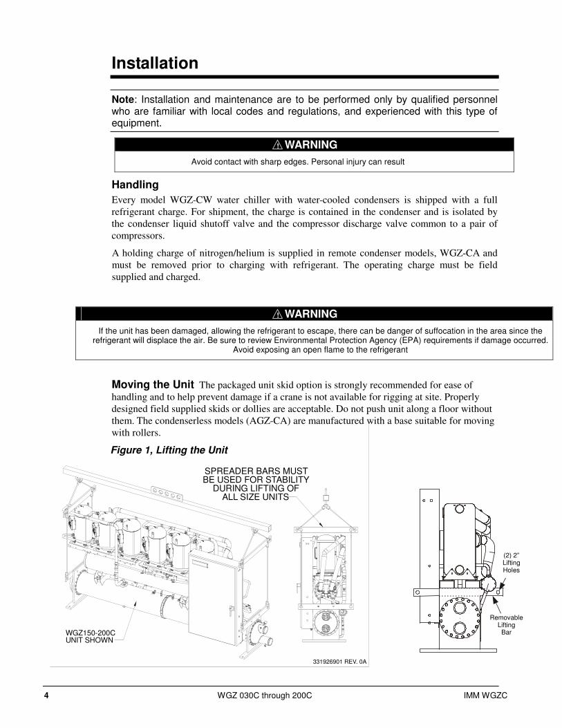
Moving the Unit The packaged unit skid option is strongly recommended for ease of
handling and to help prevent damage if a crane is not available for rigging at site. Properly
designed field supplied skids or dollies are acceptable. Do not push unit along a floor without
them. The condenserless models (AGZ-CA) are manufactured with a base suitable for moving
with rollers.
Figure 1, Lifting the Unit
! WARNING
If the unit has been damaged, allowing the refrigerant to escape, there can be danger of suffocation in the area since the refrigerant will displace the air. Be sure to review Environmental Protection Agency (EPA) requirements if damage occurred.
Avoid exposing an open flame to the refrigerant
331926901 REV. 0A
WGZ150-200CUNIT SHOWN
SPREADER BARS MUSTBE USED FOR STABILITY
DURING LIFTING OFALL SIZE UNITS
RemovableLiftingBar
(2) 2”LiftingHoles

IMM WGZC WGZ 030C through 200C 5
All moving and handling of packaged units (illustrated above) must be performed with skids
or dollies under the unit and they should not be removed until the unit is in the final location.
Never put the weight of the unit against the control box.
All moving and handling of packaged units (illustrated above) must be performed with skids
or dollies under the unit and they should not be removed until the unit is in the final location.
Never put the weight of the unit against the control box.
In moving, always apply pressure to the base on the skids only and not to the piping or other
components. A long bar will help move the unit easily. Avoid dropping the unit at the end of
the roll.
If the unit must be hoisted, lift the unit from the removable lifting arms factory-bolted to each
end of the unit adjacent to the tube sheet by attaching cables or chains to the end of the arms.
A spreader bar must be used to protect the piping, control panel and other areas of the chiller
(see Figure 1). The arms should be removed and discarded after use.
Do not attach slings to piping or equipment. Do not attempt to lift the unit by lifting points
mounted on the compressors. They are for lifting only the compressor should one need to be
removed from the unit. Move unit in the upright horizontal position at all times. Set unit
down gently when lowering from the truck or rollers.
Table 1, Lifting Loads
WGZ-CW Package Units (lbs.) WGZ CA Less Condenser Units (lbs) Model WGZ-C L1 L2 L3 L4
Shipping Weight
L1 L2 L3 L4 Shipping Weight
WGZ 030 606 633 599 573 2410 415 430 374 361 1580
WGZ 035 632 646 616 603 2496 442 445 392 390 1670
WGZ 040 639 659 630 611 2539 443 451 399 392 1685
WGZ 045 639 667 639 612 2558 444 460 407 393 1704
WGZ 050 655 689 664 631 2639 451 468 416 400 1735
WGZ 055 655 698 673 632 2658 451 476 425 402 1754
WGZ 060 655 712 688 633 2688 451 484 433 404 1771
WGZ 070 929 874 942 1001 3746 649 595 556 606 2406
WGZ 080 1066 927 1001 1151 4145 765 635 598 720 2717
WGZ 090 1076 849 1059 1343 4327 806 653 623 770 2851
WGZ 100 1059 781 1118 1515 4474 829 681 657 801 2968
WGZ 115 1054 802 1146 1506 4508 830 710 689 805 3035
WGZ 130 1055 828 1181 1505 4568 831 737 716 807 3091
WGZ 150 1684 1516 1602 1780 6581 1204 1142 1184 1249 4779
WGZ 175 1814 1528 1637 1943 6921 1245 1149 1198 1299 4891
WGZ200 1829 1550 1677 1979 7036 1265 1178 1235 1326 5004
See Figure 2 on the following page for location of lifting points.
Location
WGZ chillers are designed for indoor application and must be located in an area where
the surrounding ambient temperature is 40°F (4°C) or above. A good rule of thumb is to
place units where ambient temperatures are at least 5°F (3°C) above the leaving water
temperature.
Because of the electrical control devices, the units should not be exposed to the weather.
A plastic cover over the control box is supplied as temporary protection during shipment.
A reasonably level and sufficiently strong floor is required for the water chiller. If
necessary, additional structural members should be provided to transfer the weight of the
unit to the nearest beams.

6 WGZ 030C through 200C IMM WGZC
Control Panel
WaterConnections
4
1
3
2
LB
LF
RB
FRF
Space Requirements for Connections and Servicing
The chilled water and condenser water (on units with a water-cooled condenser) piping
enters and leaves the unit from the right side when looking at the control panel. Left-hand
condenser connections are an option. A clearance of at least 3 feet (1219 mm), or more if
codes require, should be provided beyond this piping and on all other sides and ends of
the unit for general servicing or for changing the compressors, if it ever becomes
necessary.
On units equipped with a water-cooled condenser (Type WGZ-CW) clearance should
also be provided for cleaning or removal of condenser tubes on one end of the unit. The
clearance for cleaning depends on the type of apparatus used, but can be as much as the
length of the condenser (10 feet, 3050 mm). Tube replacement requires the tube length of
10 feet (3050 mm) plus one to two feet of workspace. This space can often be provided
through a doorway or other opening.
Allow a minimum of 4-foot clearance in front of the control panel.
Placing the Unit The small amount of vibration normally encountered with the water chiller makes this
unit particularly desirable for basement or ground floor installations where the unit can
be mounted directly to the floor. The floor construction should be such that the unit will
not affect the building structure, or transmit noise and vibration into the structure.
NOTE: Springs are Model CP1E, one spring per housing.
Vibration Isolators It is recommended that isolators be used on all upper level installations or in areas where
vibration transmission is a consideration.
Figure 2, Isolator Locations
Transfer the unit as indicated
under “Moving the Unit.” In all
cases, set the unit in place and
level with a spirit level. When
spring-type isolators are
required, install springs running
under the main unit supports.
The unit should be set initially
on shims or blocks at the listed
spring free height. When all piping, wiring, flushing, charging, etc., is completed, the
springs are adjusted upward to loosen the blocks or shims that are then removed.
A rubber anti-skid pad should be used under isolators if hold-down bolts are not used.
Installation of spring isolators requires flexible piping connections and at least three feet of
flexible electrical conduit to avoid straining piping and transmitting vibration and noise.
IMM WGZC WGZ 030C through 200C 7
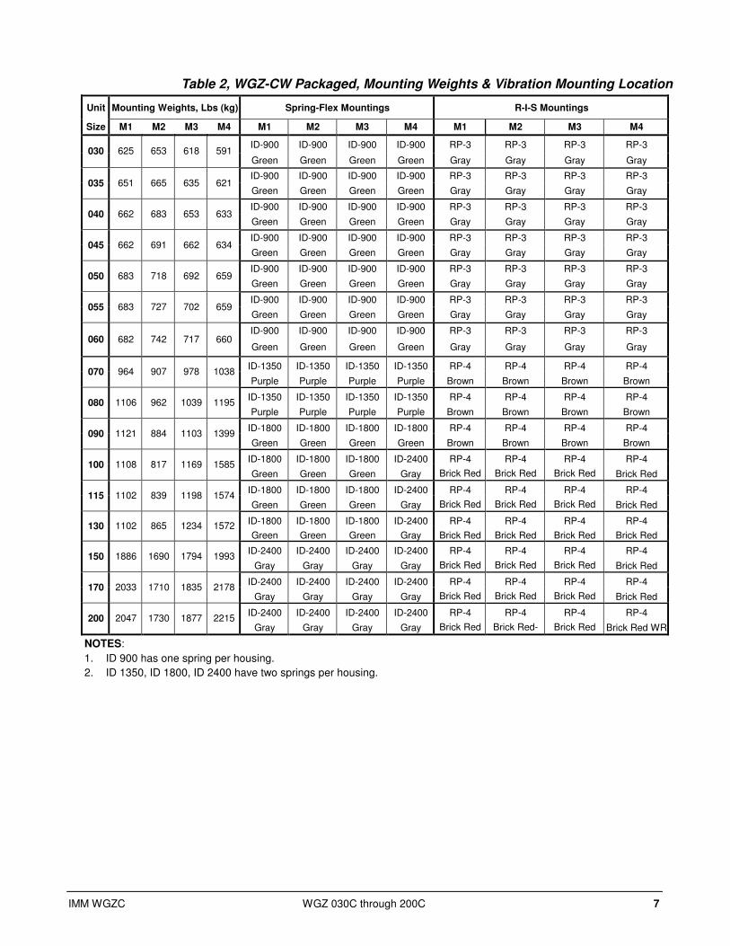
Table 2, WGZ-CW Packaged, Mounting Weights & Vibration Mounting Location
Unit Mounting Weights, Lbs (kg) Spring-Flex Mountings R-I-S Mountings
Size M1 M2 M3 M4 M1 M2 M3 M4 M1 M2 M3 M4
ID-900 ID-900 ID-900 ID-900 RP-3 RP-3 RP-3 RP-3 030 625 653 618 591
Green Green Green Green Gray Gray Gray Gray
ID-900 ID-900 ID-900 ID-900 RP-3 RP-3 RP-3 RP-3 035 651 665 635 621
Green Green Green Green Gray Gray Gray Gray
ID-900 ID-900 ID-900 ID-900 RP-3 RP-3 RP-3 RP-3 040 662 683 653 633
Green Green Green Green Gray Gray Gray Gray
ID-900 ID-900 ID-900 ID-900 RP-3 RP-3 RP-3 RP-3 045 662 691 662 634
Green Green Green Green Gray Gray Gray Gray
ID-900 ID-900 ID-900 ID-900 RP-3 RP-3 RP-3 RP-3 050 683 718 692 659
Green Green Green Green Gray Gray Gray Gray
ID-900 ID-900 ID-900 ID-900 RP-3 RP-3 RP-3 RP-3 055 683 727 702 659
Green Green Green Green Gray Gray Gray Gray
ID-900 ID-900 ID-900 ID-900 RP-3 RP-3 RP-3 RP-3 060 682 742 717 660
Green Green Green Green Gray Gray Gray Gray
ID-1350 ID-1350 ID-1350 ID-1350 RP-4 RP-4 RP-4 RP-4 070 964 907 978 1038
Purple Purple Purple Purple Brown Brown Brown Brown
ID-1350 ID-1350 ID-1350 ID-1350 RP-4 RP-4 RP-4 RP-4 080 1106 962 1039 1195
Purple Purple Purple Purple Brown Brown Brown Brown
ID-1800 ID-1800 ID-1800 ID-1800 RP-4 RP-4 RP-4 RP-4 090 1121 884 1103 1399
Green Green Green Green Brown Brown Brown Brown
ID-1800 ID-1800 ID-1800 ID-2400 RP-4 RP-4 RP-4 RP-4 100 1108 817 1169 1585
Green Green Green Gray Brick Red Brick Red Brick Red Brick Red
ID-1800 ID-1800 ID-1800 ID-2400 RP-4 RP-4 RP-4 RP-4 115 1102 839 1198 1574
Green Green Green Gray Brick Red Brick Red Brick Red Brick Red
ID-1800 ID-1800 ID-1800 ID-2400 RP-4 RP-4 RP-4 RP-4 130 1102 865 1234 1572
Green Green Green Gray Brick Red Brick Red Brick Red Brick Red
ID-2400 ID-2400 ID-2400 ID-2400 RP-4 RP-4 RP-4 RP-4 150 1886 1690 1794 1993
Gray Gray Gray Gray Brick Red Brick Red Brick Red Brick Red
ID-2400 ID-2400 ID-2400 ID-2400 RP-4 RP-4 RP-4 RP-4 170 2033 1710 1835 2178
Gray Gray Gray Gray Brick Red Brick Red Brick Red Brick Red
ID-2400 ID-2400 ID-2400 ID-2400 RP-4 RP-4 RP-4 RP-4 200 2047 1730 1877 2215
Gray Gray Gray Gray Brick Red Brick Red- Brick Red Brick Red WR
NOTES:
1. ID 900 has one spring per housing.
2. ID 1350, ID 1800, ID 2400 have two springs per housing.

8 WGZ 030C through 200C IMM WGZC
Table 3, WGZ-CA, Remote Condenser, Mounting Weights & Vibration Mounting Location
Unit Mounting Weights, Lbs Spring-Flex Mountings R-I-S Mountings
Size M1 M2 M3 M4 M5 M6 M1 M2 M3 M4 M5 M6 M1 M2 M3 M4 M5 M6
ID-900 ID-900 ID-510 ID-510 RP-3 RP-3 RP-3 RP-3 030 476 501 322 307 N/A N/A
Green Green Black Black N/A N/A
Lime Lime Lime Lime N/A N/A
ID-900 ID-900 ID-510 ID-510 RP-3 RP-3 RP-3 RP-3 035 511 516 337 334 N/A N/A
Green Green Black Black N/A N/A
Lime Lime Lime Lime N/A N/A
ID-900 ID-900 ID-510 ID-510 RP-3 RP-3 RP-3 RP-3 040 511 525 344 335 N/A N/A
Green Green Black Black N/A N/A
Lime Lime Lime Lime N/A N/A
ID-900 ID-900 ID-510 ID-510 RP-3 RP-3 RP-3 RP-3 045 512 538 353 336 N/A N/A
Green Green Black Black N/A N/A
Lime Lime Lime Lime N/A N/A
ID-900 ID-900 ID-510 ID-510 RP-3 RP-3 RP-3 RP-3 050 520 549 362 342 N/A N/A
Green Green Black Black N/A N/A
Lime Lime Lime Lime N/A N/A
ID-900 ID-900 ID-510 ID-510 RP-3 RP-3 RP-3 RP-3 055 519 561 371 343 N/A N/A
Green Green Black Black N/A N/A
Lime Lime Lime Lime N/A N/A
ID-900 ID-900 ID-510 ID-510 RP-3 RP-3 RP-3 RP-3 060 519 574 380 344 N/A N/A
Green Green Black Black N/A N/A
Lime Lime Lime Lime N/A N/A
ID-900 ID-900 ID-675 ID-900 RP3 RP3 RP3 RP3 070 738 651 509 577 N/A N/A
Green Green Purple Green N/A N/A
Gray Gray Gray Gray N/A N/A
ID-900 ID-900 ID-675 ID-900 RP-3 RP-3 RP-3 RP-3 080 884 675 532 697 N/A N/A
Green Green Purple Green N/A N/A
Gray Gray Gray Gray N/A N/A
ID-1020 ID-1020 ID-680 ID-1020 RP-3 RP-3 RP-3 RP-3 090 937 690 552 749 N/A N/A
Black Black Red Black N/A N/A
Gray Gray Gray Gray N/A N/A
ID-1020 ID-1020 ID-680 ID-1020 RP-3 RP-3 RP-3 RP-3 100 963 724 585 778 N/A N/A
Black Black Red Black N/A N/A
Gray Gray Gray Gray N/A N/A
ID-1020 ID-1020 ID-680 ID-1020 RP-3 RP-3 RP-3 RP-3 115 957. 764 621 778 N/A N/A
Black Black Red Black N/A N/A
Gray Gray Gray Gray N/A N/A
ID-1020 ID-1020 ID-680 ID-1020 RP-3 RP-3 RP-3 RP-3 130 956 804 655 779 N/A N/A
Black Black Red Black N/A N/A
Gray Gray Gray Gray N/A N/A
ID-1020 ID-1020 ID-1020 ID-1020 ID-1020 ID-1020 RP-4 RP-4 RP-4 RP-4 RP-4 RP-4 150 821 793 763 931 968 1003
Black Black Black Black Black Black Brown Brown Brown Brown Brown Brown
ID-1020 ID-1020 ID-1020 ID-1020 ID-1020 ID-1020 RP-4 RP-4 RP-4 RP-4 RP-4 RP-4 170 863 812 750 919 986 1047
Black Black Black Black Black Black Brown Brown Brown Brown Brown Brown
ID-1020 ID-1020 ID-1020 ID-1020 ID-1020 ID-1020 RP-4 RP-4 RP-4 RP-4 RP-4 RP-4 200 875 831 784 947 1000 1057
Black Black Black Black Black Black Brown Brown Brown Brown Brown Brown
NOTES:
1. ID 510, ID 675 and ID 900 have one spring per housing.
2. ID 680 and ID 1020 have two springs per housing.
Table 4, WGZ-CW, Packaged, Isolator Kit Numbers
Model Number ⇒⇒⇒⇒ 030-060 070-080 090 100-130 150-200
Spring-Flex 332320501 332320502 332320503 332320504 332320505
R-I-S 332325501 332325502 332325502 332325503 332325503
Table 5, WGZ-CA, Remote Condenser, Isolator Kit Numbers
Model Number ⇒⇒⇒⇒ 030-060 070-080 090-115 130 150-200
Spring-Flex 332320506 332320507 332320508 332320509 332320510
R-I-S 332325504 332325501 332325501 332325501 332325505

IMM WGZC WGZ 030C through 200C 9
Figure 3, Spring Flex Mounting. Two-Spring
Figure 4, Neoprene-in-Shear Mounting, RP-3
DRAWING NUMBER 3319880
2.50
1.75 (R)
.25
MOUNTING MOLDED INDURULENE. WEATHERRESISTANT (WR)
ø 3.38
4.13
5.50
ø .56 DIA.2 HOLES
1/2-13 TAP
LOCATING PIN TOBE INSTALLED HERE
ALL
DIMENSIONS
ARE
IN
DECIMAL
INCHES
10 WGZ 030C through 200C IMM WGZC
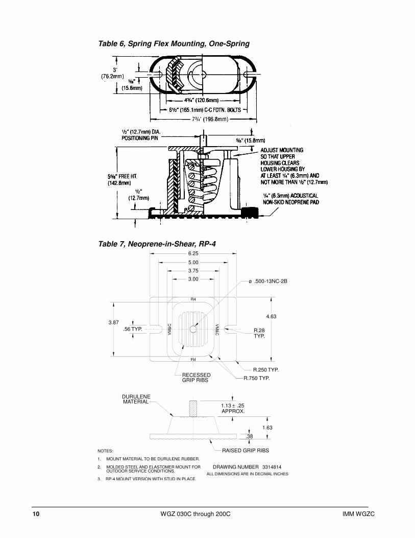
Table 6, Spring Flex Mounting, One-Spring
Table 7, Neoprene-in-Shear, RP-4
NOTES:
MOUNT MATERIAL TO BE DURULENE RUBBER.1.
MOLDED STEEL AND ELASTOMER MOUNT FOR2.OUTDOOR SERVICE CONDITIONS.
3. RP-4 MOUNT VERSION WITH STUD IN PLACE.
ALL DIMENSIONS ARE IN DECIMAL INCHES
DRAWING NUMBER 3314814
1.13 ± .25APPROX.
1.63
.38
DURULENEMATERIAL
RAISED GRIP RIBS
3.00
3.75
5.00
6.25
3.87
.56 TYP.
4.63
R.28TYP.
R.250 TYP.
R.750 TYP.RECESSEDGRIP RIBS
ø .500-13NC-2B
R4
R4
VM
&C
VM
&C
IMM WGZC WGZ 030C through 200C 11
Limitations of Operation
1. Maximum allowable condenser water pressure is 232 psig (1599 kPa).
2. Maximum condenser LWT is 115°F (46.1°C).
3. Maximum design saturated discharge temperature (SDT) is 140°F (60°C). SDT=Condensing
temperature + discharge line loss.
4. Maximum condenser leaving water temperature is 115°F (41.6C).
5. Maximum allowable water temperature to evaporator when not operating is 100°F (37.8°C).
Maximum entering water temperature for operating cycle is 90°F (32.2°C) (during system
changeover from heating to cooling cycle).
6. Minimum design leaving water temperature from the evaporator without anti-freeze protection is
40°F (4.4°C).
7. Contact your McQuay representative for operation with tower condenser water entering the chiller
below 60°F (15.6°C).
8. The maximum altitude for air-cooled condensers is 8,000 feet.
9. Consult factory for ambient operation below 0°F (-17.8°C) for air-cooled applications.

12 WGZ 030C through 200C IMM WGZC
Water Piping
Vessel Drains at Start-up Condensers are drained of water in the factory and are shipped with the condenser drain plugs in the
heads removed and stored in a bag in the control panel. Be sure to replace plugs prior to filling the
vessel with fluid.
General Due to the variety of piping practices, it is advisable to follow the recommendations of local
authorities for code compliance. They can supply the installer with the proper building and safety
codes required for a safe and proper installation.
Basically, the piping should be designed with a minimum number of bends and changes in elevation
to keep system cost down and performance up. Other piping design considerations include:
1. All piping should be installed and supported to prevent the chiller connections from bearing any
strain or weight of the system piping.
2. Vibration eliminators to reduce vibration and noise transmission to the building.
3. Shutoff valves to isolate the unit from the piping system during unit servicing.
4. Manual or automatic air vent valves at the high points of the system. Drains should be placed at
the lowest points in the system.
5. Some means of maintaining adequate system water pressure (e.g., expansion tank or regulating
valve).
6. Temperature and pressure indicators located within 3 feet (0.9 meters) of the inlet and outlet of
the vessels to aid in unit servicing.
7. A strainer or some means of removing foreign matter from the water before it enters the pump is
recommended. It should be placed far enough upstream to prevent cavitation at the pump inlet
(consult pump manufacturer for recommendations). The use of a strainer will prolong pump life
and thus maintain system performance.
Important Note A cleanable 40-mesh strainer must also be placed in the water line just prior to the inlet of the evaporator on Models WGZ 030 to 130. A 20-mesh is satisfactory on Models WGZ 150 to 200. This will aid in preventing foreign material from entering and decreasing the performance of the evaporator.
8. If the unit is used as a replacement chiller on a previously existing piping system, the system
should be thoroughly flushed prior to unit installation. Regular water analysis and chemical
water treatment on the evaporator and condenser is recommended immediately upon equipment
start-up.
9. In the event glycol is added to the water system, as an afterthought for freeze protection,
recognize that the refrigerant suction pressure will be lower, cooling performance less, and
water side pressure drop will be higher. If the percentage of glycol is large, or if propylene
glycol is used instead of ethylene glycol, the added pressure drop and loss of performance
could be substantial. Reset the freezestat and low leaving water alarm temperatures. The
freezestat is factory set to default at 36°F (2.2°C). Reset the freezestat setting to approximately
4° to 5°F (2.3° to 2.8°C) below the leaving chilled water setpoint temperature. See the section
titled “Glycol Solutions” for additional information concerning the use of glycol.
10. A preliminary leak check of the water piping should be made before filling the system.
IMM WGZC WGZ 030C through 200C 13
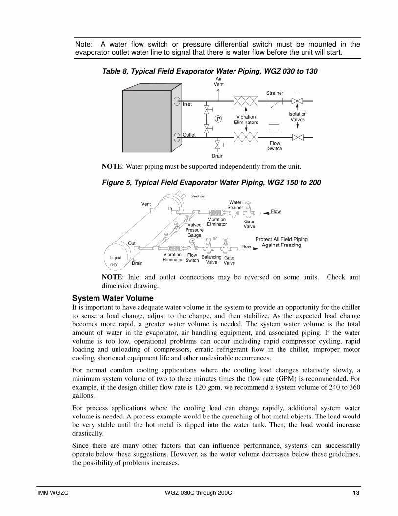
Note: A water flow switch or pressure differential switch must be mounted in the evaporator outlet water line to signal that there is water flow before the unit will start.
Table 8, Typical Field Evaporator Water Piping, WGZ 030 to 130 Air
Vent
FlowSwitch
VibrationEliminators
Drain
Outlet
Inlet
PIsolationValves
Strainer
NOTE: Water piping must be supported independently from the unit.
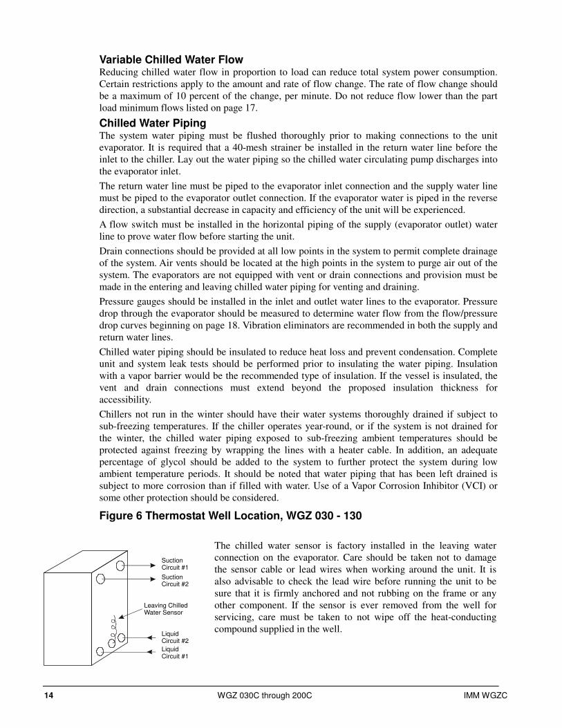
Figure 5, Typical Field Evaporator Water Piping, WGZ 150 to 200
Vent
Drain
GateValve
WaterStrainer
VibrationEliminatorValved
PressureGauge
In
OutProtect All Field Piping
Against Freezing
Flow
VibrationEliminator
FlowSwitch
BalancingValve
GateValve
Flow
Liquid
Suction
NOTE: Inlet and outlet connections may be reversed on some units. Check unit
dimension drawing.
System Water Volume It is important to have adequate water volume in the system to provide an opportunity for the chiller
to sense a load change, adjust to the change, and then stabilize. As the expected load change
becomes more rapid, a greater water volume is needed. The system water volume is the total
amount of water in the evaporator, air handling equipment, and associated piping. If the water
volume is too low, operational problems can occur including rapid compressor cycling, rapid
loading and unloading of compressors, erratic refrigerant flow in the chiller, improper motor
cooling, shortened equipment life and other undesirable occurrences.
For normal comfort cooling applications where the cooling load changes relatively slowly, a
minimum system volume of two to three minutes times the flow rate (GPM) is recommended. For
example, if the design chiller flow rate is 120 gpm, we recommend a system volume of 240 to 360
gallons.
For process applications where the cooling load can change rapidly, additional system water
volume is needed. A process example would be the quenching of hot metal objects. The load would
be very stable until the hot metal is dipped into the water tank. Then, the load would increase
drastically.
Since there are many other factors that can influence performance, systems can successfully
operate below these suggestions. However, as the water volume decreases below these guidelines,
the possibility of problems increases.
14 WGZ 030C through 200C IMM WGZC
SuctionCircuit #1
SuctionCircuit #2
LiquidCircuit #2
LiquidCircuit #1
Leaving ChilledWater Sensor
Variable Chilled Water Flow Reducing chilled water flow in proportion to load can reduce total system power consumption.
Certain restrictions apply to the amount and rate of flow change. The rate of flow change should
be a maximum of 10 percent of the change, per minute. Do not reduce flow lower than the part
load minimum flows listed on page 17.
Chilled Water Piping The system water piping must be flushed thoroughly prior to making connections to the unit
evaporator. It is required that a 40-mesh strainer be installed in the return water line before the
inlet to the chiller. Lay out the water piping so the chilled water circulating pump discharges into
the evaporator inlet.
The return water line must be piped to the evaporator inlet connection and the supply water line
must be piped to the evaporator outlet connection. If the evaporator water is piped in the reverse
direction, a substantial decrease in capacity and efficiency of the unit will be experienced.
A flow switch must be installed in the horizontal piping of the supply (evaporator outlet) water
line to prove water flow before starting the unit.
Drain connections should be provided at all low points in the system to permit complete drainage
of the system. Air vents should be located at the high points in the system to purge air out of the
system. The evaporators are not equipped with vent or drain connections and provision must be
made in the entering and leaving chilled water piping for venting and draining.
Pressure gauges should be installed in the inlet and outlet water lines to the evaporator. Pressure
drop through the evaporator should be measured to determine water flow from the flow/pressure
drop curves beginning on page 18. Vibration eliminators are recommended in both the supply and
return water lines.
Chilled water piping should be insulated to reduce heat loss and prevent condensation. Complete
unit and system leak tests should be performed prior to insulating the water piping. Insulation
with a vapor barrier would be the recommended type of insulation. If the vessel is insulated, the
vent and drain connections must extend beyond the proposed insulation thickness for
accessibility.
Chillers not run in the winter should have their water systems thoroughly drained if subject to
sub-freezing temperatures. If the chiller operates year-round, or if the system is not drained for
the winter, the chilled water piping exposed to sub-freezing ambient temperatures should be
protected against freezing by wrapping the lines with a heater cable. In addition, an adequate
percentage of glycol should be added to the system to further protect the system during low
ambient temperature periods. It should be noted that water piping that has been left drained is
subject to more corrosion than if filled with water. Use of a Vapor Corrosion Inhibitor (VCI) or
some other protection should be considered.
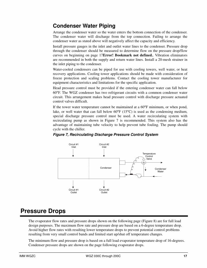
Figure 6 Thermostat Well Location, WGZ 030 - 130
The chilled water sensor is factory installed in the leaving water
connection on the evaporator. Care should be taken not to damage
the sensor cable or lead wires when working around the unit. It is
also advisable to check the lead wire before running the unit to be
sure that it is firmly anchored and not rubbing on the frame or any
other component. If the sensor is ever removed from the well for
servicing, care must be taken to not wipe off the heat-conducting
compound supplied in the well.

IMM WGZC WGZ 030C through 200C 15
! CAUTION
The thermostat bulb should not be exposed to water temperatures above 125°F (51.7°C) since this will damage it.
Flow Switch A water flow switch must be mounted in the leaving evaporator and condenser water lines to
prove adequate water flow before the unit can start. This will safeguard against slugging the
compressors on start-up. It also serves to shut down the unit in the event that water flow is
interrupted to guard against evaporator freeze-up.
Factory-mounted and wired evaporator and condenser flow switches are available as an option
If the optional factory flow switch is not supplied, a flow switch is available from McQuay under
part number 01750330. It is a “paddle” type switch and adaptable to any pipe size from 1 in. (25
mm) to 6 in. (152 mm) nominal. Certain flow rates are required to open the switch and are listed
in Table 9. Wire from switch terminals Y and R to panel terminals 33 and 43 (chilled water) and
41 and 53 (condenser water). There is also a set of normally closed contacts on the switch that
could be used for an indicator light or an alarm to indicate when a “no flow” condition exists.
1. Apply pipe sealing compound to only the threads of the switch and screw unit into 1 in. (25 mm)
reducing tee. The flow arrow must be pointed in the correct direction.
2. Piping should provide a straight length before and after the flow switch of at least five times the
pipe diameter without any valves, elbows, or other flow restricting elements.
! CAUTION
Make sure the arrow on the side of the switch is pointed in the direction of flow. The flow switch is designed to handle the control voltage and should be connected according to the wiring diagram
Table 9, Paddle-Type Flow Switch Flow Rates
inch 1 1/4 1 1/2 2 2 1/2 3 4 5 6 8 Pipe Size NOTES (x) mm 32 (2) 38 (2) 51 63 (3) 76 102 (4) 127 (4) 153 (4) 204 (5)
gpm 5.8 7.5 13.7 18.0 27.5 65.0 125.0 190.0 205.0 Flow
Lpm 1.3 1.7 3.1 4.1 6.2 14.8 28.4 43.2 46.6
gpm 3.7 5.0 9.5 12.5 19.0 50.0 101.0 158.0 170.0
Min. Adjst. No
Flow Lpm 0.8 1.1 2.2 2.8 4.3 11.4 22.9 35.9 38.6
gpm 13.3 19.2 29.0 34.5 53.0 128.0 245.0 375.0 415.0 Flow
Lpm 3.0 4.4 6.6 7.8 12.0 29.1 55.6 85.2 94.3
gpm 12.5 18.0 27.0 32.0 50.0 122.0 235.0 360.0 400.0
Max. Adjst. No
Flow Lpm 2.8 4.1 6.1 7.3 11.4 27.7 53.4 81.8 90.8
NOTES:
1. A segmented 3-inch paddle (1, 2, and 3 inches) is furnished mounted, plus a 6-inch paddle loose.
2. Flow rates for a 2-inch paddle trimmed to fit the pipe.
3. Flow rates for a 3-inch paddle trimmed to fit the pipe.
4. Flow rates for a 3-inch paddle.
5. Flow rates for a 6-inch paddle.
Glycol Solutions Chiller capacity, flow rate, evaporator pressure drop, and power input for glycol solutions can be
calculated using the following formulas and reference to Table 10 for ethylene and Table 11 for
propylene glycol.
1. Capacity, Capacity is reduced compared to that with plain water. To find the reduced value,
multiply the chiller’s capacity when using water by the capacity correction factor C to find
the chiller’s capacity when using glycol.
2. Flow, To determine evaporator gpm (or ∆T) knowing ∆T (or gpm) and capacity:

16 WGZ 030C through 200C IMM WGZC
TablesFromGCorrectionFlowxT
CapacityGlycolxGPMGlycol
∆=
24
For Metric Applications -- Determine evaporator lps (or ∆T) knowing ∆T (or lps)
and kW:
TablesfromGCorrectionFlowxTx
kWLpsGlycol
∆=
18.4
3. Pressure Drop, To determine glycol pressure drop through the cooler, enter the
water pressure drop graph on page 17 at the actual glycol flow. Multiply the water
pressure drop found there by P to obtain corrected glycol pressure drop.
4. Power, To determine glycol system kW, multiply the water system kW by factor K.
Test coolant with a clean, accurate, glycol solution hydrometer (similar to that found in
service stations) to determine the freezing point. Obtain percent glycol from the freezing
point found in Table 10 or Table 11. On glycol applications the supplier normally
recommends that a minimum of 25% solution by weight be used for protection against
corrosion or the use of additional inhibitors.
Note: The effect of glycol in the condenser is negligible. As glycol increases in temperature, its characteristics have a tendency to mirror those of water. Therefore, for selection purposes, there is no derate in capacity for glycol in the condenser.
Table 10, Ethylene Glycol
Freezing Point Percent Glycol °F °C
C (Capacity) K (Power) G (Flow) P (Pressure
Drop)
10 26 -3 0.991 0.996 1.013 1.070
20 18 -8 0.982 0.992 1.040 1.129
30 7 -14 0.972 0.986 1.074 1.181
40 -7 -22 0.961 0.976 1.121 1.263
50 -28 -33 0.946 0.966 1.178 1.308
Table 11, Propylene Glycol
Freezing Point Percent Glycol °F °C
C (Capacity) K (Power) G (Flow) P (Pressure
Drop)
10 26 -3 0.987 0.992 1.010 1.068
20 19 -7 0.975 0.985 1.028 1.147
30 9 -13 0.962 0.978 1.050 1.248
40 -5 -21 0.946 0.971 1.078 1.366
50 -27 -33 0.929 0.965 1.116 1.481
! CAUTION
Do not use automotive antifreeze. Industrial glycols must be used. Automotive antifreeze contains inhibitors that causes plating on copper tubes. The type and handling of glycol used must be consistent with local codes.
IMM WGZC WGZ 030C through 200C 17
Circuit #1 Outlet
Condenser
TemperatureControlValve
CondenserWater
Circuit #2 Outlet
Circuit #1 Inlet
Circuit #2 Inlet
Condenser Water Piping Arrange the condenser water so the water enters the bottom connection of the condenser.
The condenser water will discharge from the top connection. Failing to arrange the
condenser water as stated above will negatively affect the capacity and efficiency.
Install pressure gauges in the inlet and outlet water lines to the condenser. Pressure drop
through the condenser should be measured to determine flow on the pressure drop/flow
curves on beginning on page 17Error! Bookmark not defined.. Vibration eliminators
are recommended in both the supply and return water lines. Install a 20-mesh strainer in
the inlet piping to the condenser.
Water-cooled condensers can be piped for use with cooling towers, well water, or heat
recovery applications. Cooling tower applications should be made with consideration of
freeze protection and scaling problems. Contact the cooling tower manufacturer for
equipment characteristics and limitations for the specific application.
Head pressure control must be provided if the entering condenser water can fall below
60°F. The WGZ condenser has two refrigerant circuits with a common condenser water
circuit. This arrangement makes head pressure control with discharge pressure actuated
control valves difficult.
If the tower water temperature cannot be maintained at a 60°F minimum, or when pond,
lake, or well water that can fall below 60°F (15°C) is used as the condensing medium,
special discharge pressure control must be used. A water recirculating system with
recirculating pump as shown in Figure 7 is recommended. This system also has the
advantage of maintaining tube velocity to help prevent tube fouling. The pump should
cycle with the chiller.
Figure 7, Recirculating Discharge Pressure Control System
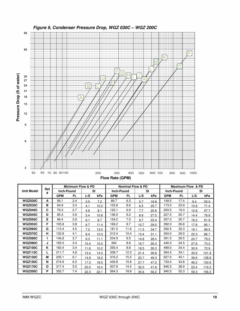
Pressure Drops
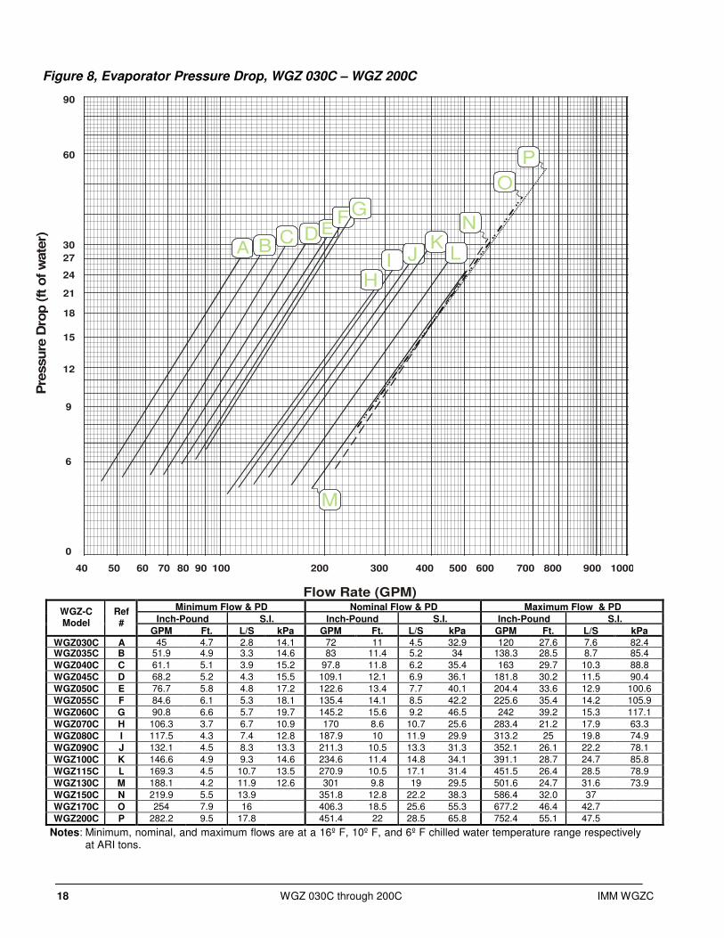
The evaporator flow rates and pressure drops shown on the following page (Figure 8) are for full load
design purposes. The maximum flow rate and pressure drop are based on a 6-degree temperature drop.
Avoid higher flow rates with resulting lower temperature drops to prevent potential control problems
resulting from very small control bands and limited start up/shut off temperature changes.
The minimum flow and pressure drop is based on a full load evaporator temperature drop of 16-degrees.
Condenser pressure drops are shown on the page following evaporator drops.
18 WGZ 030C through 200C IMM WGZC
Figure 8, Evaporator Pressure Drop, WGZ 030C – WGZ 200C
Minimum Flow & PD Nominal Flow & PD Maximum Flow & PD
Inch-Pound S.I. Inch-Pound S.I. Inch-Pound S.I. WGZ-C Model
Ref #
GPM Ft. L/S kPa GPM Ft. L/S kPa GPM Ft. L/S kPa
WGZ030C A 45 4.7 2.8 14.1 72 11 4.5 32.9 120 27.6 7.6 82.4 WGZ035C B 51.9 4.9 3.3 14.6 83 11.4 5.2 34 138.3 28.5 8.7 85.4
WGZ040C C 61.1 5.1 3.9 15.2 97.8 11.8 6.2 35.4 163 29.7 10.3 88.8
WGZ045C D 68.2 5.2 4.3 15.5 109.1 12.1 6.9 36.1 181.8 30.2 11.5 90.4
WGZ050C E 76.7 5.8 4.8 17.2 122.6 13.4 7.7 40.1 204.4 33.6 12.9 100.6
WGZ055C F 84.6 6.1 5.3 18.1 135.4 14.1 8.5 42.2 225.6 35.4 14.2 105.9
WGZ060C G 90.8 6.6 5.7 19.7 145.2 15.6 9.2 46.5 242 39.2 15.3 117.1
WGZ070C H 106.3 3.7 6.7 10.9 170 8.6 10.7 25.6 283.4 21.2 17.9 63.3
WGZ080C I 117.5 4.3 7.4 12.8 187.9 10 11.9 29.9 313.2 25 19.8 74.9
WGZ090C J 132.1 4.5 8.3 13.3 211.3 10.5 13.3 31.3 352.1 26.1 22.2 78.1
WGZ100C K 146.6 4.9 9.3 14.6 234.6 11.4 14.8 34.1 391.1 28.7 24.7 85.8
WGZ115C L 169.3 4.5 10.7 13.5 270.9 10.5 17.1 31.4 451.5 26.4 28.5 78.9
WGZ130C M 188.1 4.2 11.9 12.6 301 9.8 19 29.5 501.6 24.7 31.6 73.9
WGZ150C N 219.9 5.5 13.9 351.8 12.8 22.2 38.3 586.4 32.0 37
WGZ170C O 254 7.9 16 406.3 18.5 25.6 55.3 677.2 46.4 42.7
WGZ200C P 282.2 9.5 17.8 451.4 22 28.5 65.8 752.4 55.1 47.5
Notes: Minimum, nominal, and maximum flows are at a 16º F, 10º F, and 6º F chilled water temperature range respectively at ARI tons.
900 1000
CB
D KLJI
AE
FG
H
0
6
12
18
24
27
30
9
21
15
60
90
40 50 60 70 80 90 100 200 300 400 500 600
Pre
ssu
re D
rop (
ft o
f w
ate
r)
Flow Rate (GPM)
700 800
O
P
N
M
IMM WGZC WGZ 030C through 200C 19
Figure 9, Condenser Pressure Drop, WGZ 030C – WGZ 200C
Minimum Flow & PD Nominal Flow & PD Maximum Flow & PD
Inch-Pound SI Inch-Pound SI Inch-Pound SI Unit Model Ref #
GPM Ft. L/S kPa GPM Ft. L/S kPa GPM Ft. L/S kPa
WGZ030C A 56.1 2.4 3.5 7.2 89.7 6.3 5.7 18.8 149.5 17.4 9.4 52.0 WGZ035C B 64.9 3.4 4.1 10.2 103.8 8.6 6.5 25.7 173.0 23.9 10.9 71.4
WGZ040C C 76.3 2.7 4.8 8.1 122.1 6.9 7.7 20.6 203.5 19.3 12.8 57.7
WGZ045C D 85.3 3.6 5.4 10.8 136.5 9.2 8.6 27.5 227.5 25.7 14.4 76.8
WGZ050C E 96.4 2.9 6.1 8.7 154.2 7.5 9.7 22.4 257.0 20.7 16.2 61.9
WGZ055C F 105.8 3.8 6.7 11.4 169.2 9.7 10.7 29.0 282.0 26.8 17.8 80.1
WGZ060C G 113.4 4.5 7.2 13.5 181.5 11.6 11.5 34.7 302.5 32.3 19.1 96.5
WGZ070C H 132.8 4.1 8.4 12.3 212.4 10.4 13.4 31.1 354.0 29.0 22.3 86.7
WGZ080C I 146.8 3.7 9.3 11.1 234.9 9.5 14.8 28.4 391.5 26.5 24.7 79.2
WGZ090C J 165.0 3.4 10.4 10.2 264 8.8 16.7 26.3 440.0 24.5 27.8 73.2
WGZ100C K 183.4 3.4 11.6 10.2 293.4 8.8 18.5 26.3 489.0 24.4 30.9 72.9
WGZ115C L 211.7 4.8 13.4 14.3 338.7 12.3 21.4 36.8 564.5 34.1 35.6 101.9
WGZ130C M 235.1 6.1 14.8 18.2 376.2 15.5 23.7 46.3 627.0 43.1 39.6 128.8
WGZ150C N 274.9 6.2 17.3 18.5 439.8 15.8 27.7 47.2 733.0 43.8 46.2 130.9
WGZ170C O 317.4 5.5 20.0 16.4 507.9 14.0 32.0 41.8 846.5 38.9 53.4 116.3
WGZ200C P 352.7 7.4 22.3 22.1 564.3 18.8 35.6 56.2 940.5 52.3 59.3 156.3
Pre
ss
ure
Dro
p (
ft o
f w
ate
r)
Flow Rate (GPM)

20 WGZ 030C through 200C IMM WGZC
Refrigerant Piping
Unit with Remote Condenser General
Refrigerant piping, to and from the unit, should be sized and installed according to the
latest ASHRAE Handbook. It is important that the unit piping be properly supported with
sound and vibration isolation between tubing and hanger, and that the discharge lines be
looped at the condenser and trapped at the compressor to prevent refrigerant and oil from
draining into the compressors. Looping the discharge line also provides greater line
flexibility.
NOTE: Do not install any refrigerant piping underground.
The discharge gas valves, liquid line solenoids, filter-driers, moisture indicators, and
expansion valves are all factory mounted as standard equipment with the water chiller.
For remote condenser application (WGZ-CA) such as air-cooled or evaporative
condenser, the chillers are shipped with a nitrogen/helium holding charge. The unit is
evacuated in the factory to 500 microns before charging with the nitrogen.
The liquid line has a shutoff valve upstream from the liquid line solenoid valve and a
copper tube cap to be brazed on this line after test to seal this line for shipment.
The discharge line has a ball valve installed between the compressor and the discharge
stub tube with a copper tube cap brazed on the line after test to seal it for shipment.
The discharge gas valves, liquid line solenoids, filter-driers, moisture indicators, and
expansion valves are all factory-mounted as standard equipment with the water chiller.
! DANGER
Do not apply heat, such as a brazing torch, to a sealed unit, vessel, or component. Internal gases can increase the internal pressure and cause a life-threatening explosion. Open the system when heating. The short line between a valve and brazed end cap can be drilled to vent it. Note that the valve may leak and the entire unit charge may be open to the cap.
It is important that the unit be kept tightly closed until the remote condenser is installed,
piped to the unit and the high side evacuated.
The installer must leak test the remote piping with nitrogen at 150 psig maximum
pressure, then properly evacuate the piping system to 500 microns or below and provide
the operating charge of R-410A. When the field piping has been leak tested, evacuated,
and is ready to charge, the unit valves can be opened and the system is ready to pressure
test, evacuate and charge the entire system together at one time.
After the equipment is properly installed, leak tested, and evacuated, it can be charged
with R-410A, and run at design load conditions. Add charge until the liquid line sight
glass is clear, with no bubbles flowing to the expansion valve. Total operating charge will
depend on the air-cooled condenser used and volume of the refrigerant piping.
NOTE: On WGZ-CA units (units with remote condensers), the installer is required to
record the refrigerant charge by stamping the total charge and the charge per circuit on
the serial plate in the appropriate blocks provided for this purpose.
The following discussion is intended for use as a general guide to the piping of air-cooled
condensers.

IMM WGZC WGZ 030C through 200C 21
Discharge lines must be designed to handle oil properly and to protect the compressor from
damage that can result from condensing liquid refrigerant in the line during shutdown. Total
friction loss for discharge lines of 3 to 6 psi (20.7 to 41.4 kPa) is considered good design.
Careful consideration must be given for sizing each section of piping to insure that gas
velocities are sufficient at all operating conditions to carry oil. If the velocity in a vertical
discharge riser is too low, considerable oil can collect in the riser and the horizontal header,
causing the compressor to lose its oil and result in damage due to lack of lubrication. When
the compressor load is increased, the oil that had collected during reduced loads can be carried
as a slug through the system and back to the compressor, where a sudden increase of oil
concentration can cause liquid slugging and damage to the compressor.
Any horizontal run of discharge piping should be pitched away from the compressor
approximately 1/8 inch (6.4 mm) per foot (meter) or more. This is necessary to move, by
gravity, any oil lying in the header. Oil pockets must be avoided because oil needed in the
compressor would collect at such points and the compressor crankcase can become starved.
It is recommended that any discharge lines coming into a horizontal discharge header rise
above the centerline of the discharge header. This is necessary to prevent any oil or condensed
liquid from draining to the compressor heads when the compressor is not running.
In designing liquid lines, it is important that the liquid reach the expansion valve without flash
gas since this gas will reduce the capacity of the valve. Because “flashing” can be caused by a
pressure drop in the liquid line, the pressure losses due to friction and changes in static head
should be kept to a minimum.
A check valve must be installed in the liquid line in all applications where the ambient
temperature can drop below the equipment room temperature. This prevents liquid migration
to the condenser, helps maintain a supply of refrigerant in the liquid line for initial start-up,
and keeps liquid line pressure high enough on “off” cycle to keep the expansion valve closed.
On systems as described above, a relief valve or relief-type check valve, must be used in the
liquid line as shown in piping systems (shown in and Its purpose is to relieve dangerous
hydraulic pressures that could be created as cool liquid refrigerant trapped in the line between
the check valve and the expansion or shutoff valve warms up. Install a relief device in the hot
gas piping at the condenser coil as shown in and Figure 11. Install a discharge check valve in
the discharge line, in a horizontal run, close to the condenser.
Recommended Line Sizing The following tables provide recommended line sizing for the field piping. Final design
should be based on ASHRAE design standards.

22 WGZ 030C through 200C IMM WGZC
Table 12, Equivalent Feet for Fittings
Fitting Type 7/8 1 1/8 1 3/8 1 5/8 2 1/8 2 5/8 3 1/8
Elbows
90º Standard 2.0 2.6 3.3 4.0 5.0 6.0 7.5
90º Long Radius 1.4 1.7 2.3 2.6 3.3 4.1 5.0
90º Street 3.2 4.1 5.6 6.3 8.2 10 12
45º Standard 0.9 1.3 1.7 2.1 2.6 3.2 4.0
45º Street 1.5 2.1 3.0 3.4 4.5 5.2 6.4
180º Bend 3.2 4.1 5.6 6.3 8.2 10 12
Tees
Full Size 1.4 1.7 2.3 2.6 3.3 4.1 5.0
Reducing 2.0 2.6 3.3 4.0 5.0 6.0 7.5
Valves
Globe Valve, Open 22 29 38 43 55 69 84
Gate Valve, Open 0.9 1.0 1.5 1.8 2.3 2.8 3.2
Angle Valve, Open 9.0 12 15 18 24 29 35
Table 13, Maximum Line Size for Oil Carry Up a Discharge Riser, R-410A
Unit Size WGZ
030
WGZ
035
WGZ
040
WGZ
045
WGZ
050
WGZ
055
WGZ
060
WGZ
070
WGZ
080
WGZ
090
Line Size
(in.) 1 5/8 1 5/8 2 1/8 2 1/8 2 1/8 2 1/8 2 1/8 2 1/8 2 5/8 2 5/8
Unit Size WGZ
100
WGZ
115
WGZ
130
WGZ
150
WGZ
170
WGZ
200
Line Size
(in.) 2 5/8 3 1/8 3 1/8 2 5/8 3 1/8 3 1/8
Table 14, Recommended Liquid Line Size, R-410A
Recommended Liquid Line Size (in.)
Up to Up to Up to Up to Up to Unit Model
WGZ-CB
Connection
Size at Unit
(in.) 50 Equiv. Ft 75 Equiv. Ft 100 Equiv. Ft 125 Equiv. Ft 150 Equiv. Ft
WGZ 030 7/8" 7/8 " 7/8 " 7/8 " 7/8 " 7/8 "
WGZ 035 7/8" 7/8 " 7/8 " 7/8 " 7/8 " 1 1/8 "
WGZ 040 7/8" 7/8 " 7/8 " 7/8 " 1 1/8 " 1 1/8 "
WGZ 045 7/8" 7/8 " 7/8 " 7/8 " 1 1/8 " 1 1/8 "
WGZ 050 7/8" 7/8 " 7/8 " 7/8 " 1 1/8 " 1 1/8 "
WGZ 055 7/8" 7/8 " 7/8 " 1 1/8” 1 1/8 " 1 1/8 "
WGZ 060 7/8" 7/8 “ 7/8 " 1 1/8 " 1 1/8 " 1 1/8 "
WGZ 070 1 1/8” 1 1/8” 1 1/8 " 1 1/8 " 1 1/8 " 1 1/8”
WGZ 080 1 1/8” 1 1/8 " 1 1/8 " 1 1/8” 1 1/8” 1 1/8”
WGZ 090 1 1/8” 1 1/8 " 1 1/8 " 1 1/8” 1 1/8” 1 1/8”
WGZ 100 1 1/8” 1 1/8 " 1 1/8 " 1 1/8” 1 1/8” 1 1/8”
WGZ 115 1 1/8” 1 1/8 " 1 1/8 " 1 1/8” 1 3/8” 1 3/8”
WGZ 130 1 1/8” 1 1/8 " 1 3/8” 1 1/8” 1 3/8” 1 3/8”
WGZ 150 1 3/8” 1 3/8” 1 1/8 " 1 3/8” 1 3/8” 1 3/8”
WGZ 170 1 3/8” 1 3/8” 1 1/8 " 1 3/8” 1 3/8” 1 3/8”
WGZ-200 1 3/8” 1 3/8” 1 1/8 " 1 3/8” 1 3/8” 1 3/8”
IMM WGZC WGZ 030C through 200C 23
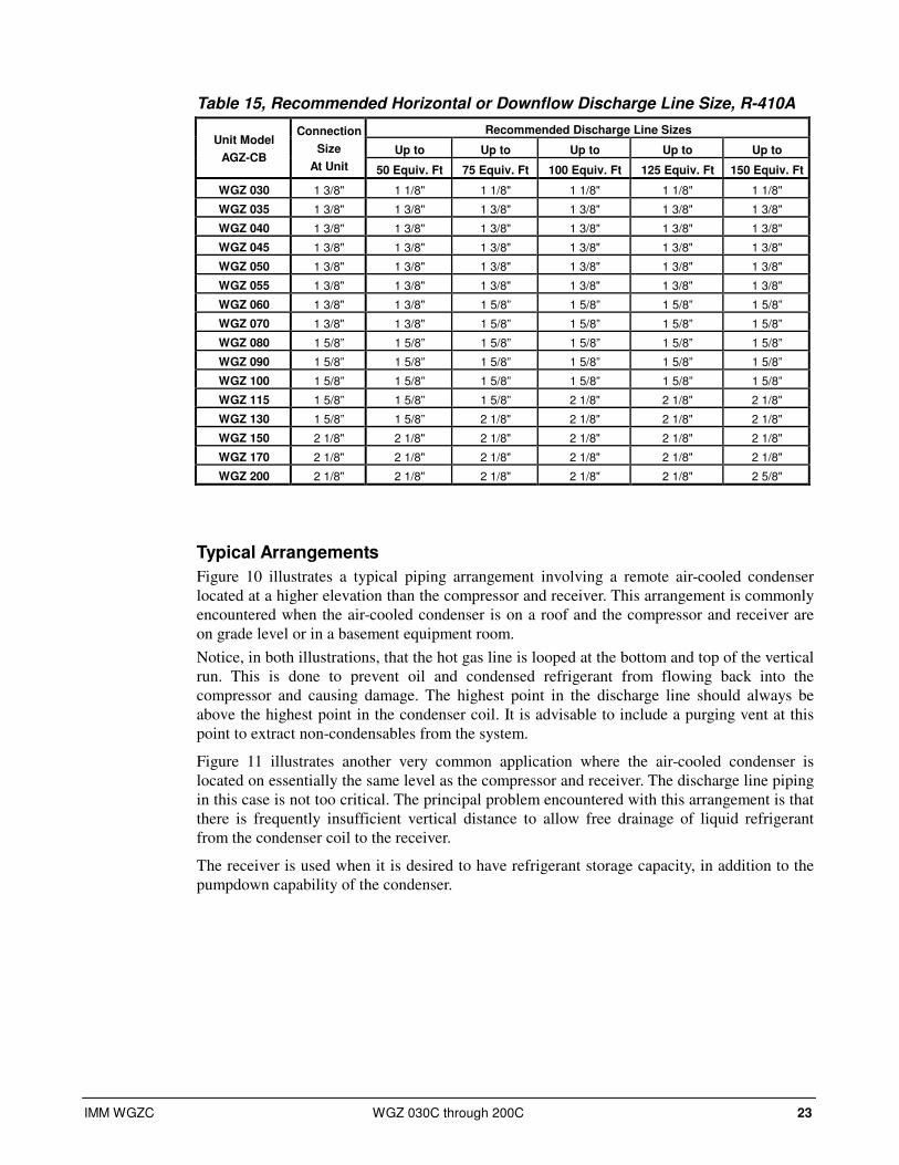
Table 15, Recommended Horizontal or Downflow Discharge Line Size, R-410A
Recommended Discharge Line Sizes
Up to Up to Up to Up to Up to Unit Model
AGZ-CB
Connection
Size
At Unit 50 Equiv. Ft 75 Equiv. Ft 100 Equiv. Ft 125 Equiv. Ft 150 Equiv. Ft
WGZ 030 1 3/8" 1 1/8" 1 1/8" 1 1/8" 1 1/8" 1 1/8"
WGZ 035 1 3/8" 1 3/8" 1 3/8" 1 3/8" 1 3/8" 1 3/8"
WGZ 040 1 3/8" 1 3/8" 1 3/8" 1 3/8" 1 3/8" 1 3/8"
WGZ 045 1 3/8" 1 3/8" 1 3/8" 1 3/8" 1 3/8" 1 3/8"
WGZ 050 1 3/8" 1 3/8" 1 3/8" 1 3/8" 1 3/8" 1 3/8"
WGZ 055 1 3/8" 1 3/8" 1 3/8" 1 3/8" 1 3/8" 1 3/8"
WGZ 060 1 3/8" 1 3/8" 1 5/8” 1 5/8” 1 5/8” 1 5/8”
WGZ 070 1 3/8" 1 3/8" 1 5/8” 1 5/8” 1 5/8” 1 5/8”
WGZ 080 1 5/8” 1 5/8” 1 5/8” 1 5/8” 1 5/8” 1 5/8”
WGZ 090 1 5/8” 1 5/8” 1 5/8” 1 5/8” 1 5/8” 1 5/8”
WGZ 100 1 5/8” 1 5/8” 1 5/8” 1 5/8” 1 5/8” 1 5/8”
WGZ 115 1 5/8” 1 5/8” 1 5/8” 2 1/8" 2 1/8" 2 1/8"
WGZ 130 1 5/8” 1 5/8” 2 1/8" 2 1/8" 2 1/8" 2 1/8"
WGZ 150 2 1/8" 2 1/8" 2 1/8" 2 1/8" 2 1/8" 2 1/8"
WGZ 170 2 1/8" 2 1/8" 2 1/8" 2 1/8" 2 1/8" 2 1/8"
WGZ 200 2 1/8" 2 1/8" 2 1/8" 2 1/8" 2 1/8" 2 5/8"
Typical Arrangements
Figure 10 illustrates a typical piping arrangement involving a remote air-cooled condenser
located at a higher elevation than the compressor and receiver. This arrangement is commonly
encountered when the air-cooled condenser is on a roof and the compressor and receiver are
on grade level or in a basement equipment room.
Notice, in both illustrations, that the hot gas line is looped at the bottom and top of the vertical
run. This is done to prevent oil and condensed refrigerant from flowing back into the
compressor and causing damage. The highest point in the discharge line should always be
above the highest point in the condenser coil. It is advisable to include a purging vent at this
point to extract non-condensables from the system.
Figure 11 illustrates another very common application where the air-cooled condenser is
located on essentially the same level as the compressor and receiver. The discharge line piping
in this case is not too critical. The principal problem encountered with this arrangement is that
there is frequently insufficient vertical distance to allow free drainage of liquid refrigerant
from the condenser coil to the receiver.
The receiver is used when it is desired to have refrigerant storage capacity, in addition to the
pumpdown capability of the condenser.

24 WGZ 030C through 200C IMM WGZC
Condenser
Relief Valve
Check Valve
Purge Valve
Discharge Line
Loop
Receiver
ReceiverBypass
ToEvap.
PreferredSubcoolerHook-up
Relief Valve(Vent to Outdoorsor to Condenser Sideof Liquid LineCheck Valve)
Pitch
CheckValve
Subcooler
Condenser
Relief Valve
Check Valve
Purge Valve
Relief Valve(Vent to Outdoorsor to Condenser Sideof Liquid LineCheck Valve)
Pitch
CheckValve
Discharge Line
Receiver
ReceiverBypass
ToEvap.
PreferredSubcoolerHook-up
CheckValve
Subcooler
Figure 10, Condenser Above Compressor and Optional Receiver Installation
Figure 11, Condenser and Compressor on Same Level, Optional Receiver Installation
The receiver shown is optional and not used on many installations. It is bypassed during
normal operation.

IMM WGZC WGZ 030C through 200C 25
Factory-Mounted Condenser Units with the standard water-cooled, factory-mounted condenser are provided with
complete refrigerant piping and full operating refrigerant charge at the factory.
There is a remote possibility on water-cooled units utilizing low temperature pond or
river water as a condensing medium, and if the water valves leak, that the condenser and
liquid line refrigerant temperature could drop below the equipment room temperature on
the “off” cycle. This problem only arises during periods when cold water continues to
circulate through the condenser and the unit remains off due to satisfied cooling load.
If this condition occurs:
1. Cycle the condenser pump off with the unit.
2. Check the liquid line solenoid valve for proper operation.
Relief Valve Piping
The ANSI/ASHRAE Standard 15, Safety Standard for Refrigeration Systems, specifies
that pressure relief valves on vessels containing Group 1 refrigerant (R-410a) “shall
discharge to the atmosphere at a location not less than 15 feet (4.6 meters) above the
adjoining ground level and not less than 20 feet (6.1 meters) from any window,
ventilation opening or exit in any building.” The piping must be provided with a rain cap
at the outside terminating point and with a drain at the low point on the vent piping to
prevent water buildup on the atmospheric side of the relief valve. Also, a flexible pipe
section should be installed in the line to eliminate any piping stress on the relief valve(s).
The size of the discharge pipe from the pressure relief valve should not be less than the
size of the pressure relief outlet. When two or more vessels are piped together, the
common header and piping to the atmosphere should not be less than the sum of the area
of each of the lines connected to the header.
NOTE: Fittings should be provided to permit vent piping to be easily disconnected for inspection or replacement of the relief valve.
Figure 12, Relief Valve Piping

26 WGZ 030C through 200C IMM WGZC
Dimensions
Packaged Chillers
Figure 13, WGZ 030CW through WGZ 060CW
CHILLER WATER CONNECTION SIZE (NOM) VICTAULIC
CONDENSER WATER CONNECTION SIZE (NOM) VICTAULIC
CENTER OF GRAVITY WGZ MODEL NUMBER
IN (MM) A IN (MM) X Y Z
WGZ030C 2.5 (64) 107.4 (2728) 4 (102) 59.2 22.4 14.1
WGZ035C 2.5 (64) 108.4 (2753) 4 (102) 59.9 22.8 14.2
WGZ040C 2.5 (64) 109.8 (2789) 4 (102) 59.6 22.8 14.2
WGZ045C 2.5 (64) 111.5 (2832 4 (102) 59.2 22.9 14.2
WGZ050C 2.5 (64) 113.3 (2878) 4 (102) 59.0 23.3 14.2
WGZ055C 2.5 (64) 115.0 (2921) 4 (102) 58.7 23.4 14.2
WGZ060C 2.5 (64) 116.7 (2965) 4 (102) 58.0 23.6 14.3
CONDENSER
INLET
121.13075
9.7246
134.63419
3.8
REF.98 " X "
" Y "
3.9100
.875 DIA MOUNTING HOLES (4)
INLET
OUTLET
OUTLET
RELIEF VALVES
MICROTECH II USER INTERFACE
VENT
DRAIN
CIRCUIT 1CIRCUIT 2
30.1763
32.8832
" Z "
" Y "
23.5597
2.051
20.0508
29.0737
13.3338
32.0813
8.0204
14.0354
29.2742
44.91139
12.4314
63.41609
40.01016
EVAPORATOR
REMOVABLEDISC. HANDLE
REMOVE BRKT.FOR SHIPPING
ONLYPOWER
CONNECTIONS
CONTROLCONNECTION
.88 KNOCKOUTSON OPPOSITE SIDE
.88 KNOCKOUTS
"A"
CONTROL BOX
WATERCONNECTIONS
L1 / M1 L2 / M2
L3 / M3L4 / M4
WGZ030C-060CPackaged Unit
331929701
IMM WGZC WGZ 030C through 200C 27
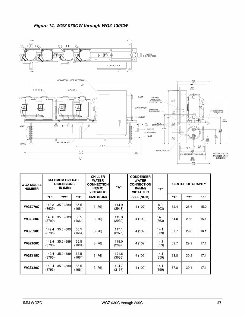
Figure 14, WGZ 070CW through WGZ 130CW
MAXIMUM OVERALL DIMENSIONS
IN (MM) CENTER OF GRAVITY WGZ MODEL
NUMBER
“L” “W” “H”
CHILLER WATER
CONNECTION IN(MM)
VICTAULIC
SIZE (NOM)
“A”
CONDENSER WATER
CONNECTION IN(MM)
VICTAULIC
SIZE (NOM)
“T”
“X” “Y” “Z”
WGZ070C 143.3 (3639)
35.0 (889) 65.5 (1664)
3 (76) 114.9 (2918)
4 (102) 8.0
(203) 62.4 28.6 15.0
WGZ080C 149.6 (3799)
35.0 (889) 65.5 (1664)
3 (76) 115.3 (2930)
4 (102) 14.3 (363)
64.8 29.3 15.1
WGZ090C 149.4 (3795)
35.0 (889) 65.5 (1664)
3 (76) 117.1 (2975)
4 (102) 14.1 (359)
67.7 29.6 16.1
WGZ100C 149.4 (3795)
35.0 (889) 65.5 (1664)
3 (76) 118.0 (2997)
4 (102) 14.1 (359)
69.7 29.9 17.1
WGZ115C 149.4 (3795)
35.0 (889) 65.5 (1664)
3 (76) 121.6 (3088)
4 (102) 14.1 (359)
68.8 30.2 17.1
WGZ130C 149.4 (3795)
35.0 (889) 65.5 (1664)
3 (76) 124.7 (3167)
4 (102) 14.1 (359)
67.8 30.4 17.1
CONDENSER
121.13075"T"
14.2361
"L"
"A"
" X "
4.0102
.875 DIA MOUNTING HOLES (4)
INLET
INLET
OUTLET
OUTLET
EVAPORATOR
RELIEF VALVES
MICROTECH II USER INTERFACE
VENT
DRAIN
CIRCUIT 2 CIRCUIT 1
29.0737
13.0330
32.3821
"W"
" Y "
" Z "
23.5597
2.051
10.0253
17.9454
32.8834
57.61462
14.5369
20.0508
"H"
32.0813
40.01016
40.21021
REMOVABLEDISC. HANDLE REMOVE BRKT.
FOR SHIPPINGONLY
POWERCONNECTIONS
CONTROLCONNECTION
.88 KNOCKOUTSON OPPOSITE SIDE
.88 KNOCKOUTS
CONTROL BOX
WATERCONNECTIONS
L1 / M1 L2 / M2
L3 / M3L4 / M4
WGZ070-130CWPackaged Chiller
331929801

28 WGZ 030C through 200C IMM WGZC
Figure 15, WGZ 150CW through WGZ 200CW
CHILLER WATER CONNECTION SIZE (NOM) VICTAULIC
CONDENSER WATER CONNECTION SIZE (NOM) VICTAULIC
CENTER OF GRAVITY WGZ MODEL NUMBER
IN (MM) IN (MM) X Y Z
WGZ150C 8 (203) 5 (127) 68.7 38.6 14.9
WGZ170C 8 (203) 5 (127) 66.3 38.3 15.0
WGZ200C 8 (203) 5 (127) 66.6 38.7 15.1
CONDENSER
EVAPORATOROUTLET
10.9276
145.13685
14.2361
170.24322
" X "
" Y "
4.0102
INLET
OUTLET
EVAPORATORINLET
RELIEF VALVES
MICROTECH II USER INTERFACE
VENT
VENT
DRAINDRAIN
29.0737
13.3337
33.8859
36.5
T.B.D.927
77.71973
" Z "
23.5597
2.051
15.5394
17.0432
9.6243
18.3464
36.9
EVAPINLET/
OUTLET
938
32.0813
5.0127
40.01016
41.21046
.875 DIA MOUNTING HOLES (4)
.88 KNOCKOUT
REMOVABLEDISC HANDLE
REMOVE BRKT.FOR SHIPPING
ONLY
CONTROLCONNECTION
.88 KNOCKOUTSON OPPOSITE SIDE
POWERCONNECTIONS
23.5596
77.21961
1.334
CIRCUIT 1CIRCUIT 2
WGZ150CW-200CWPackaged Chiller
331929901
IMM WGZC WGZ 030C through 200C 29
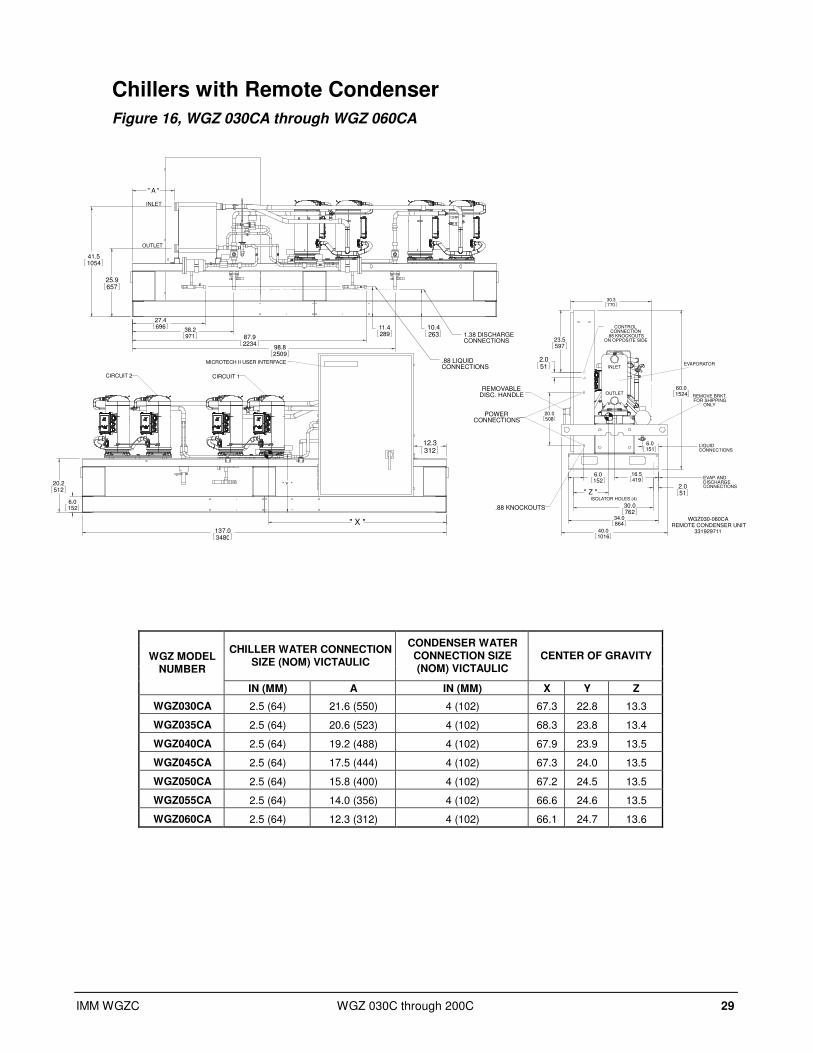
Chillers with Remote Condenser
Figure 16, WGZ 030CA through WGZ 060CA
CHILLER WATER CONNECTION SIZE (NOM) VICTAULIC
CONDENSER WATER CONNECTION SIZE (NOM) VICTAULIC
CENTER OF GRAVITY WGZ MODEL NUMBER
IN (MM) A IN (MM) X Y Z
WGZ030CA 2.5 (64) 21.6 (550) 4 (102) 67.3 22.8 13.3
WGZ035CA 2.5 (64) 20.6 (523) 4 (102) 68.3 23.8 13.4
WGZ040CA 2.5 (64) 19.2 (488) 4 (102) 67.9 23.9 13.5
WGZ045CA 2.5 (64) 17.5 (444) 4 (102) 67.3 24.0 13.5
WGZ050CA 2.5 (64) 15.8 (400) 4 (102) 67.2 24.5 13.5
WGZ055CA 2.5 (64) 14.0 (356) 4 (102) 66.6 24.6 13.5
WGZ060CA 2.5 (64) 12.3 (312) 4 (102) 66.1 24.7 13.6
WGZ030-060CA REMOTE CONDENSER UNIT
331929711
" X "
" Y "
137.03480
12.3312
6.0152
20.2512
MICROTECH II USER INTERFACE
CIRCUIT 1CIRCUIT 2
1.38 DISCHARGECONNECTIONS
.88 LIQUIDCONNECTIONS
30.3770
" Z "
23.5597
2.051
30.0762
2.051
20.0508
34.0864
40.01016
6.0152
6.0151
16.5419
60.01524
EVAPORATOR
REMOVABLEDISC. HANDLE REMOVE BRKT.
FOR SHIPPINGONLY
POWERCONNECTIONS
CONTROLCONNECTION
.88 KNOCKOUTSON OPPOSITE SIDE
.88 KNOCKOUTS
ISOLATOR HOLES (4)
OUTLET
INLET
LIQUIDCONNECTIONS
EVAP. ANDDISCHARGECONNECTIONS
25.9657
41.51054
" A "
27.4696
38.2971 87.9
223498.82509
11.4289
10.4263
OUTLET
INLET
30 WGZ 030C through 200C IMM WGZC
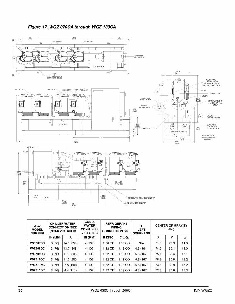
Figure 17, WGZ 070CA through WGZ 130CA
CHILLER WATER CONNECTION SIZE (NOM) VICTAULIC
COND. WATER
CONN. SIZE VICTAULIC
REFRIGERANT PIPING
CONNECTION SIZE
CENTER OF GRAVITY (IN.)
WGZ MODEL
NUMBER
IN (MM) A IN (MM) B DISC. C LIQ.
T LEFT
OVERHANG
X Y Z
WGZ070C 3 (76) 14.1 (359) 4 (102) 1.38 OD 1.13 OD N/A 71.5 29.3 14.9
WGZ080C 3 (76) 13.7 (348) 4 (102) 1.62 OD 1.13 OD 6.3 (161) 74.9 30.1 15.0
WGZ090C 3 (76) 11.9 (303) 4 (102) 1.62 OD 1.13 OD 6.6 (167) 75.7 30.4 15.1
WGZ100C 3 (76) 11.0 (280) 4 (102) 1.62 OD 1.13 OD 6.6 (167) 75.2 30.6 15.2
WGZ115C 3 (76) 7.5 (190) 4 (102) 1.62 OD 1.13 OD 6.6 (167) 73.8 30.8 15.2
WGZ130C 3 (76) 4.4 (111) 4 (102) 1.62 OD 1.13 OD 6.6 (167) 72.6 30.9 15.3
" T "
" Y "
" X "
137.03480
12.3312
6.0152
23.2588
MICROTECH II USER INTERFACECIRCUIT 1CIRCUIT 2
DISCHARGE CONNECTIONS "B"
LIQUID CONNECTIONS "C"
32.3821
23.5597
2.051
30.0762
2.051" Z "
20.0508
34.0864
40.01016
6.0152
60.01524
4.0101
15.5394
EVAPORATOR
REMOVABLEDISC. HANDLE
REMOVE BRKT.FOR SHIPPING
ONLYPOWER
CONNECTIONS
CONTROLCONNECTION
.88 KNOCKOUTSON OPPOSITE SIDE
.88 KNOCKOUTS
ISOLATOR HOLES (4)
OUTLET
INLET
LIQUIDCONNECTIONS
EVAP. ANDDISCHARGECONNECTIONS
52.01322
18.5469
27.3694
"A "
13.3338
12.4±.25316±6.35
38.2971
89.22266
98.82509
OUTLET
INLET
WGZ070-130CAUnit less condenser
331929811
21.0533
95.02413
21.05332.0
51
30.0762
2.051
%%c.75
ISOLATOR HOLES IN THEBOTTOM OF THE BASE
19
CONTROL BOX
CIRCUIT 1CIRCUIT 2
L1 L2
L3L4
M1 M2
M3M4
EVAP WATERCONNECTIONS
IMM WGZC WGZ 030C through 200C 31
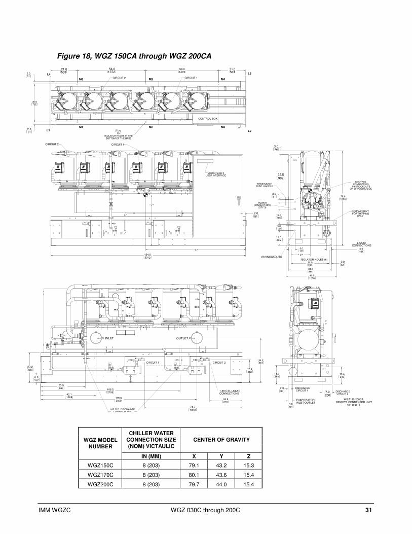
Figure 18, WGZ 150CA through WGZ 200CA
CHILLER WATER CONNECTION SIZE (NOM) VICTAULIC
CENTER OF GRAVITY WGZ MODEL NUMBER
IN (MM) X Y Z
WGZ150C 8 (203) 79.1 43.2 15.3
WGZ170C 8 (203) 80.1 43.6 15.4
WGZ200C 8 (203) 79.7 44.0 15.4
" Y "
" X "
154.03912
2.051
MICROTECH IIUSER INTERFACE
CIRCUIT 1CIRCUIT 2
WGZ150-200CA REMOTE CONDENSER UNIT
331929911
2.051
30.0762
2.051
" Z "
5.0127
12.0305
35.5902
3.076
75.01905
12.0305
34.0864
40.01016
4.0101
5.0127
REMOVABLEDISC. HANDLE
REMOVE BRKT.FOR SHIPPING
ONLY
CONTROLCONNECTION
.88 KNOCKOUTSON OPPOSITE SIDE
.88 KNOCKOUTSISOLATOR HOLES (6)
POWERCONNECTIONS
(QTY 3)
LIQUIDCONNECTIONS
106.52705
33.9862
42.11069 119.3
3030
34.2867
24.9631
74.71898
17.4443
6.0152
23.2588
OUTLETINLET
1.62 O.D. DISCHARGECONNECTIONS
1.38 O.D. LIQUIDCONNECTIONS
CIRCUIT 1 CIRCUIT 2
2.360 7.9
200
14.5368
13.4340
3.690
EVAPORATORINLET/OUTLET
DISCHARGECIRCUIT 1 DISCHARGE
CIRCUIT 2
21.0533
30.0762
2.051
2.051
21.0533
58.01473
54.01372
.75
ISOLATOR HOLES IN THEBOTTOM OF THE BASE
19
CONTROL BOX
CIRCUIT 1CIRCUIT 2
L1 L2
L3L4
M1 M3
M4M6
M2
M5

32 WGZ 030C through 200C IMM WGZC
Physical Data
Packaged Chillers
Table 16, WGZ 030CW – WGZ 055CW
WGZ UNIT SIZE 30 35 40 45 50 55
Unit capacity @ ARI tons, (kW) 30.0 (105.5) 34.6 (121.7) 40.7 (143.1) 45.5 (160.0) 51.4 (180.8) 56.4 (198.4)
No. Circuits 2 2 2 2 2 2
COMPRESSORS
Nominal Tons 7.5 7.5 9 9 10 10 12 12 13 13 13 15
Number Per Circuit 2 2 2 2 2 2 2 2 2 2 2 2
CAPACITY REDUCTION STEPS - PERCENT OF COMPRESSOR DISPLACEMENT
Staging, Circuit #1 in Lead 25 / 50 / 75 / 100 25 / 50 / 75 / 100 25 / 50 / 75 / 100 25 / 50 / 75 / 100 25 / 50 / 75 / 100 23 / 50 / 73 / 100
Staging, Circuit #2 in Lead 25 / 50 / 75 / 100 25 / 50 / 75 / 100 25 / 50 / 75 / 100 25 / 50 / 75 / 100 25 / 50 / 75 / 100 27 / 50 / 77 / 100
Oil Charge per Compressor oz., (l) 85 (2.5) 110 (3.3) 110 (3.3) 110 (3.3) 110 (3.3) 110 (3.3)
CONDENSER
Number 1 1 1 1 1 1
No. Refrigerant Circuits 2 2 2 2 2 2
Diameter, in., (mm) 10 (254) 10 (254) 10 (254) 10 (254) 10 (254) 10 (254)
Tube Length, in., (mm) 120 (3048) 120 (3048) 120 (3048) 120 (3048) 120 (3048) 120 (3048)
Design W.P.PSIG, (kPa):
Refrigerant Side 500 (3447) 500 (3447) 500 (3447) 500 (3447) 500 (3447) 500 (3447)
Water Side 232 (1599) 232 (1599) 232 (1599) 232 (1599) 232 (1599) 232 (1599)
Pump-Out Capacity, lb., (kg) (3) 245.8 (111.7) 245.8 (111.7) 228.2 (103.7) 228.2 (103.7) 205.4 (93.4) 205.4 (93.4)
Conn.In & Out, in, (mm) Victaulic 4 (102) 4 (102) 4 (102) 4 (102) 4 (102) 4 (102)
Relief Valve, Flare In., (mm) ⅝ (15.9) ⅝ (15.9) ⅝ (15.9) ⅝ (15.9) ⅝ (15.9) ⅝ (15.9)
Purge Valve, Flare In., (mm) ½ (12.7) ½ (12.7) ½ (12.7) ½ (12.7) ½ (12.7) ½ (12.7)
Vent & Drain, in. (mm) NPT ¼ (6.4) ¼ (6.4) ¼ (6.4) ¼ (6.4) ¼ (6.4) ¼ (6.4)
Liquid Subcooling Integral Integral Integral Integral Integral Integral
EVAPORATOR, BRAZED-PLATE
Number 1 1 1 1 1 1
No. Refrigerant Circuits 2 2 2 2 2 2
Water Volume, gallons, (l) 1.9 (7.1) 2.2 (8.3) 2.4 (9.1) 2.9 (11.0) 3.4 (12.8) 3.7 (14.0)
Refrig. Side D.W.P. Psig, (kPa) 450 (3102) 450 (3102) 450 (3102) 450 (3102) 450 (3102) 450 (3102)
Water Side D.W.P,. psig, (kPa) 653 (4500) 653 (4500) 653 (4500) 653 (4500) 653 (4500) 653 (4500)
Conn. In & Out, in. (mm) Victaulic 2.5 (65) 2.5 (65) 2.5 (65) 2.5 (65) 2.5 (65) 2.5 (65)
Relief Valve, Flare in., (mm) ⅝ (15.9) ⅝ (15.9) ⅝ (15.9) ⅝ (15.9) ⅝ (15.9) ⅝ (15.9)
Vent & Drain Field Field Field Field Field Field
UNIT DIMENSIONS
Length In., (mm) 136.0 (3455) 136.0 (3455) 136.0 (3455) 136.0 (3455) 136.0 (3455) 136.0 (3455)
Width In., (mm) 32.8 (832) 32.8 (832) 32.8 (832) 32.8 (832) 32.8 (832) 32.8 (832)
Height In., (mm) 63.4 (1609) 63.4 (1609) 63.4 (1609) 63.4 (1609) 63.4 (1609) 63.4 (1609)
UNIT WEIGHTS
Operating Weight, lb., (kg) 2486 (1128) 2572 (1167) 2631 (1193) 2650 (1202) 2752 (1248) 2771 (1257)
Shipping Weight, lb., (kg) 2410 (1093) 2496 (1132) 2539 (1152) 2558 (1160) 2639 (1197) 2658 (1206)
Cir # 1,Opn. Charge, lb.,(kg) R410a 45 (20.5) 45 (20.5) 47 (21.4) 47 (21.4) 47 (21.4) 50 (22.7)
Cir # 2,Opn. Charge, lb.,(kg) R410a 45 (20.5) 45 (20.5) 47 (21.4) 47 (21.4) 47 (21.4) 50 (22.7)
Notes:
1. Certified in accordance with ARI Standard 550/590-2003.
2. 90% Full R-410a at 90°F (32°C) per unit.

IMM WGZC WGZ 030C through 200C 33
Table 17, WGZ060CW - WGZ100CW
WGZ UNIT SIZE 60 70 80 90 100
Unit capacity @ ARI tons, (kW) (1) 60.5 (212.8) 70.8 (249.0) 78.3 (275.4) 88.0 (309.5) 97.8 (344.0)
No. Circuits 2 2 2 2 2
COMPRESSORS
Nominal Tons 15 15 15/20 15/20 20 20 20 26 26 26
Number per Circuit4 2 2 2 2 2 2 2 2 2 2
CAPACITY REDUCTION STEPS - PERCENT OF COMPRESSOR DISPLACEMENT
Staging, 4 Stages, Circuit #1 in Lead 25 / 50 / 75 / 100 22 / 50 / 72 / 100 25 / 50 / 75 / 100 25 / 50 / 75 / 100 25 / 50 / 75 / 100
Staging, 4 Stages, Circuit #2 in Lead 25 / 50 / 75 / 100 22 / 50 / 72 / 100 25 / 50 / 75 / 100 25 / 50 / 75 / 100 25 / 50 / 75 / 100
Oil Charge, per compressor oz. (l) 110 (3.3) 110 (3.3) 158 (4.7)
110 (3.3) 158 (4.7)
158 (4.7) 158 (4.7)
230 (6.8)230 (6.8)
CONDENSER
Number 1 1 1 1 1
No. Refrigerant Circuits 2 2 2 2 2
Diameter, in. (mm) 10 (254) 14 (356) 14 (356) 14 (356) 14 (356)
Tube Length, in. (mm) 120 (3048) 120 (3048) 120 (3048) 120 (3048) 120 (3048)
Design W.P., psig (kPa):
Refrigerant Side 500 (3447) 500 (3447) 500 (3447) 500 (3447) 500 (3447)
Water Side 232 (1599) 232 (1599) 232 (1599) 232 (1599) 232 (1599)
No. of Passes 2 2 2 2 2
Pump-Out Capacity lb., (kg) (3) 205.4 (93.4) 415.1 (188.7) 397.5 (180.7) 371.1 (168.7) 344.7 (156.7)
Conn. In & Out, in., (mm) Victaulic 4 (102) 4 (102) 4 (102) 4 (102) 4 (102)
Relief Valve, Flare in., (mm) ⅝ (15.9) ⅝ (15.9) ⅝ (15.9) ⅝ (15.9) ⅝ (15.9)
Purge Valve, Flare in. (mm) ½ (12.7) ½ (12.7) ½ (12.7) ½ (12.7) ½ (12.7)
Vent & Drain, in. (mm) NPT ¼ (6.4) ¼ (6.4) ¼ (6.4) ¼ (6.4) ¼ (6.4)
Liquid Subcooling Integral Integral Integral Integral Integral
EVAPORATOR, BRAZED-PLATE
Number 1 1 1 1 1
No. Refrigerant Circuits 2 2 2 2 2
Water Volume, gallons (l) 4.2 (15.9) 6.4 (24.3) 6.6 (24.9) 7.5 (28.4) 8.0 (30.2)
Refrigerant Side D.W.P., psig, (kPa) 450 (3102) 450 (3102) 450 (3102) 450 (3102) 450 (3102)
Water Side D.W.P., psig, (kPa) 653 (4500) 653 (4500) 653 (4500) 653 (4500) 653 (4500)
Conn. In & Out, in. (mm) Victaulic 2.5 (65) 3 (76) 3 (76) 3 (76) 3 (76)
Relief Valve, Flare in., (mm) ⅝ (15.9) ⅝ (15.9) ⅝ (15.9) ⅝ (15.9) ⅝ (15.9)
Vent & Drain Field Field Field Field Field
UNIT DIMENSIONS
Length, in. (mm) 136.0 (3455) 143.3 (3639) 149.6 (3799) 149.4 (3795) 149.4 (3795)
Width, in. (mm) 32.8 (832) 35.0 (889) 35.0 (889) 35.0 (889) 35.0 (889)
Height, in. (mm) 63.4 (1609) 65.5 (1664) 65.5 (1664) 65.5 (1664) 65.5 (1664)
UNIT WEIGHTS
Operating Wt, lb., (kg) 2801 (1271) 3887 (1763) 4302 (1951) 4507 (2044) 4678 (2122)
Shipping Wt, lb. (kg) 2688 (1219) 3746 (1699) 4145 (1880) 4327 (1963) 4474 (2029)
Cir # 1,Opn. Charge, lb, (kg) R410a 50 (22.7) 74 (34.1) 80 (36.4) 80 (36.4) 90 (40.9)
Cir # 2,Opn. Charge, lb.,(kg) R410a 50 (22.7) 74 (34.1) 80 (36.4) 80 (36.4) 90 (40.9)
Notes:
1. Certified in accordance with ARI Standard 550/590-2003.-
2. Units WGZ030 to 130 have two parallel compressors per circuit. Units WGZ150 to 200 have three parallel compressors per circuit.
3. 90% Full R-410a at 90°F (32°C) per unit.

34 WGZ 030C through 200C IMM WGZC
Table 18, WGZ115CW - WGZ200CW
WGZ UNIT SIZE 115 130 150 170 200
Unit capacity @ ARI. tons, (kW) (1) 112.9 (397.1) 125.4 (441.0) 146.6 (515.6) 169.3 (595.4) 188.1 (661.5)
No. Circuits 2 2 2 2 2
COMPRESSORS
Nominal Tons 26/30 26/30 30 30 26 26 26 30 30 30
Number Per Circuit 2 2 2 2 3 3 3 3 3 3
CAPACITY REDUCTION STEPS - PERCENT OF COMPRESSOR DISPLACEMENT
Staging, 4 Stages, Circuit #1 in Lead 22 / 50 / 72 / 100 25 / 50 / 75 / 100 17 / 33 / 50 / 67
/ 83 / 100 15 / 33 / 48 / 67 / 81
/ 100 17 / 33 / 50 / 67 /
83 / 100
Staging, 4 Stages, Circuit #2 in Lead 22 / 50 / 72 / 100 25 / 50 / 75 / 100 17 / 33 / 50 / 67
83 / 100 19 / 33 / 52 / 67
86 /100 17 / 33 / 50 / 67 /
83 / 100
Oil Charge, per compressor oz. (l) 230 (6.8 )/ 213 (6.3)
230 (6.8 )/ 213 (6.3)
213 (6.3) 230 (6.8) 230 (6.8) 213 (6.3) 213 (6.3)
CONDENSER
Number 1 1 1 1 1
No. Refrigerant Circuits 2 2 2 2 2
Diameter, in. (mm) 14 (356) 14 (356) 16 (406.4) 16 (406.4) 16 (406.4)
Tube Length, in. (mm) 120 (3048) 120 (3048) 144 (3658) 144 (3658) 144 (3658)
Design W.P., psig (kPa):
Refrigerant Side 500 (3447) 500 (3447) 500 (3447) 500 (3447) 500 (3447)
Water Side 232 (1599) 232 (1599) 232 (1599) 232 (1599) 232 (1599)
Pump-Out Capacity lb., (kg) (3) 344.7 (156.7) 344.7 (156.7) 572.3 (260.1) 508.9 (231.3) 508.9 (231.3)
Water Conn In & Out, in., (mm) (4) 4 (102) 4 (102) 5 (127) 5 (127) 5 (127)
Relief Valve, Flare in., (mm) ⅝ (15.9) ⅝ (15.9) ⅝ (15.9) ⅝ (15.9) ⅝ (15.9)
Purge Valve, Flare in. (mm) ½ (12.7) ½ (12.7) ½ (12.7) ½ (12.7) ½ (12.7)
Vent & Drain, in. (mm) FPT ¼ 6.4) ¼ 6.4) ¼ 6.4) ¼ 6.4) ¼ 6.4)
Liquid Subcooling Integral Integral Integral Integral Integral
EVAPORATOR, BRAZED-PLATE ⇒⇒⇒⇒ SHELL-AND-TUBE
Number 1 1 1 1 1
No. Refrigerant Circuits 2 2 2 2 2
Water Volume, gallons (l) 8.5 (32.1) 10.5 (39.7) 57.6 (218.0) 56.9 (215.4) 56.9 (215.4)
Refrigerant Side D.W.P., psig, (kPa) 450 (3102) 450 (3102) 450 (3102) 450 (3102) 450 (3102)
Water Side D.W.P., psig, (kPa) 653 (4500) 653 (4500) 150 (1034) 150 (1034) 150 (1034)
Water Conn.In & Out, in. (mm) Victaulic 3 (76) 3 (76) 8 (203) 8 (203) 8 (203)
Relief Valve, Flare in., (mm) ⅝ (15.9) ⅝ (15.9)
Drain & Vent size, in. (mm) Field Field ½ (12.7) ½ (12.7) ½ (12.7)
UNIT DIMENSIONS
Length, in. (mm) 149.4 (3795) 149.4 (3795) 170.2 (4322) 170.2 (4322) 170.2 (4322)
Width, in. (mm) 35.0 (889) 35.0 (889) 36.5 (927) 36.5 (927) 36.5 (927)
Height, in. (mm) 65.5 (1664) 65.5 (1664) 77.7 (1973) 77.7 (1973) 77.7 (1973)
UNIT WEIGHTS
Operating Wt, lb., (kg) 4712 (2137) 4772 (2165) 7370 (3343) 7758 (3519) 7873 (3571)
Shipping Wt, lb. (kg) 4508 (2045) 4568 (2072) 6581 (2985) 6921 (3139) 7036 (3192)
Cir #1, Op. Charge, lb., (kg) R-410a 100 (45.5) 100 (45.5) 150 (68.2) 150 (68.2) 150 (68.2)
Cir #2, Op. Charge, lb., (kg) R-410a 100 (45.5) 100 (45.5) 150 (68.2) 150 (68.2) 150 (68.2)
Notes:
1. Certified in accordance with ARI Standard 550/590-2003.
2. Units WGZ030 to 130 have two parallel compressors per circuit, units WGZ150 to 200 have three parallel compressors per circuit.
3. 90% Full R-410a at 90°F (32°C) per unit.
IMM WGZC WGZ 030C through 200C 35
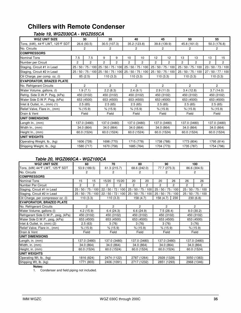
Chillers with Remote Condenser Table 19, WGZ030CA - WGZ055CA WGZ UNIT SIZE 30 35 40 45 50 55
Tons, (kW), 44°F LWT, 125°F SDT 26.6 (93.5) 30.5 (107.3) 35.2 (123.8) 39.8 (139.9) 45.8 (161.0) 50.3 (176.8)
No. Circuits 2 2 2 2 2 2
COMPRESSORS
Nominal Tons 7.5 7.5 9 9 10 10 12 12 13 13 13 15
Number per Circuit 2 2 2 2 2 2 2 2 2 2 2 2
Staging, Circuit #1 in Lead 25 / 50 / 75 / 100 25 / 50 / 75 / 100 25 / 50 / 75 / 100 25 / 50 / 75 / 100 25 / 50 / 75 / 100 23 / 50 / 73 / 100
Staging, Circuit #2 in Lead 25 / 50 / 75 / 100 25 / 50 / 75 / 100 25 / 50 / 75 / 100 25 / 50 / 75 / 100 25 / 50 / 75 / 100 27 / 50 / 77 / 100
Oil Charge, per comp. oz, (l) 85 (2.5) 110 (3.3) 110 (3.3) 110 (3.3) 110 (3.3) 110 (3.3)
EVAPORATOR, BRAZED PLATE
No. Refrigerant Circuits 2 2 2 2 2 2
Water Volume, gallons, (l) 1.9 (7.1) 2.2 (8.3) 2.4 (9.1) 2.9 (11.0) 3.4 (12.8) 3.7 (14.0)
Refrig. Side D.W.P. Psig, (kPa) 450 (3102) 450 (3102) 450 (3102) 450 (3102) 450 (3102) 450 (3102)
Water Side D.W.P. Psig, (kPa) 653 (4500) 653 (4500) 653 (4500) 653 (4500) 653 (4500) 653 (4500)
Inlet & Outlet, in., (mm) (1) 2.5 (65) 2.5 (65) 2.5 (65) 2.5 (65) 2.5 (65) 2.5 (65)
Relief Valve, Flare in., (mm) ⅝ (15.9) ⅝ (15.9) ⅝ (15.9) ⅝ (15.9) ⅝ (15.9) ⅝ (15.9)
Drain & Vent Field Field Field Field Field Field
UNIT DIMENSIONS
Length In., (mm) 137.0 (3480) 137.0 (3480) 137.0 (3480) 137.0 (3480) 137.0 (3480) 137.0 (3480)
Width In., (mm) 34.0 (864) 34.0 (864) 34.0 (864) 34.0 (864) 34.0 (864) 34.0 (864)
Height In., (mm) 60.0 (1524) 60.0 (1524) 60.0 (1524) 60.0 (1524) 60.0 (1524) 60.0 (1524)
UNIT WEIGHTS
Operating Weight, lb., (kg) 1606 (728) 1698 (770) 1715 (778) 1738 (788) 1773 (804) 1795 (814)
Shipping Weight, lb., (kg) 1580 (717) 1670 (758) 1685 (764) 1704 (773) 1735 (787) 1754 (796)
Table 20, WGZ060CA - WGZ100CA WGZ UNIT SIZE 60 70 80 90 100
Tons, (kW) 44°F LWT, 125°F SDT 53.9 (189.5) 61.3 (215.7) 68.6 (242.0) 77.7 (273.3) 86.6 (304.5)
No. Circuits 2 2 2 2 2
COMPRESSORS
Nominal Tons 15 15 15/20 15/20 20 20 20 26 26 26
Number Per Circuit 2 2 2 2 2 2 2 2 2 2
Staging, Circuit #1 in Lead 25 / 50 / 75 / 100 22 / 50 / 72 / 100 25 / 50 / 75 / 100 25 / 50 / 75 / 100 25 / 50 / 75 / 100
Staging, Circuit #2 in Lead 25 / 50 / 75 / 100 22 / 50 / 72 / 100 25 / 50 / 75 / 100 25 / 50 / 75 / 100 25 / 50 / 75 / 100
Oil Charge, per compressor oz. (l) 110 (3.3) 110 (3.3) 158 (4.7)
158 (4.7) 158 (4.7) 230 (6.8)
230 (6.8)
EVAPORATOR, BRAZED PLATE
No. Refrigerant Circuits 2 2 2 2 2
Water Volume, gallons (l) 4.2 (15.9) 6.4 (24.3) 6.6 (24.9) 7.5 (28.4) 8.0 (30.2)
Refrigerant Side D.W.P., psig, (kPa) 450 (3102) 450 (3102) 450 (3102) 450 (3102) 450 (3102)
Water Side D.W.P., psig, (kPa) 653 (4500) 653 (4500) 653 (4500) 653 (4500) 653 (4500)
Inlet & Outlet, in. (mm) (2) 2.5 (63) 3 (76) 3 (76) 3 (76) 3 (76)
Relief Valve, Flare in., (mm) ⅝ (15.9) ⅝ (15.9) ⅝ (15.9) ⅝ (15.9) ⅝ (15.9)
Drain & Vent Field Field Field Field Field
UNIT DIMENSIONS
Length, in. (mm) 137.0 (3480) 137.0 (3480) 137.0 (3480) 137.0 (3480) 137.0 (3480)
Width, in. (mm) 34.0 (864) 34.0 (864) 34.0 (864) 34.0 (864) 34.0 (864)
Height, in. (mm) 60.0 (1524) 60.0 (1524) 60.0 (1524) 60.0 (1524) 60.0 (1524)
UNIT WEIGHTS
Operating Wt, lb., (kg) 1816 (824) 2474 (1122) 2787 (1264) 2928 (1328) 3050 (1383)
Shipping Wt, lb. (kg) 1771 (803) 2406 (1091) 2717 (1232) 2851 (1293) 2968 (1346)
Notes: 1. Condenser and field piping not included.

36 WGZ 030C through 200C IMM WGZC
Table 21, WGZ115CA – WGZ200CA
WGZ UNIT SIZE 115 130 150 170 200
Tons, (kW)44°F LWT, 125°F SDT 100.1 (352.2) 111.4 (391.7) 129.9 (456.8) 150.2 (528.3) 170.6 (599.8)
No. Circuits 2 2 2 2 2
COMPRESSORS
Nominal Tons 26/30 26/30 30 30 26 26 26 30 30 30
Number Per Circuit 2 2 2 2 3 3 3 3 3 3
Staging, Circuit #1 in Lead 22 / 50 / 72 / 100 25 / 50 / 75 / 100 17 / 33 / 50 / 67 / 83
/ 100 15 / 33 / 48 / 67 /
81 / 100 17 / 33 / 50 / 67 /
83 / 100
Staging, Circuit #2 in Lead 22 / 50 / 72 / 100 25 / 50 / 75 / 100 17 / 33 / 50 / 67 / 83
/ 100 19 / 33 / 52 / 67 /
86 / 100 17 / 33 / 50 / 67 /
83 / 100
Oil Charge, per compressor oz. (l) 230 (6.8 ) 213 (6.3)
213 (6.3) 230 (6.8) 230 (6.8) 213 (6.3) 213 (6.3)
EVAPORATOR, BRAZED PLATE------------------------------------------------⇒⇒⇒⇒ SHELL-AND-TUBE
No. Refrigerant Circuits 2 2 2 2 2
Water Volume, gallons (l) 8.5 (32.1) 10.5 (39.7) 57.6 (218.0) 56.9 (215.4) 56.9 (215.4)
Refrigerant Side D.W.P., psig, (kPa)
450 (3102) 450 (3102) 450 (3102) 450 (3102) 450 (3102)
Water Side D.W.P., psig, (kPa) 653 (4500) 653 (4500) 150 (1034) 150 (1034) 150 (1034)
Water Connections:
In & Out, in. (mm), victaulic 3 (76) 3 (76) 8 (203) 8 (203) 8 (203)
Relief Valve, Flare in., (mm) ⅝ (15.9) ⅝ (15.9) ⅝ (15.9) ⅝ (15.9) ⅝ (15.9)
Drain & Vent Field Field ½ (12.7) ½ (12.7) ½ (12.7)
UNIT DIMENSIONS
Length, in. (mm) 137.0 (3480) 137.0 (3480) 154.0 (3912) 154.0 (3912) 154.0 (3912)
Width, in. (mm) 34.0 (864) 34.0 (864) 34.0 (864) 34.0 (864) 34.0 (864)
Height, in. (mm) 60.0 (1524) 60.0 (1524) 75.0 (1905) 75.0 (1905) 75.0 (1905)
UNIT WEIGHTS
Operating Wt, lb., (kg) 3120 (1415) 3194 (1449) 5279 (2395) 5385 (2443) 5498 (2494)
Shipping Wt, lb. (kg) 3035 (1377) 3091 (1402) 4779 (2168) 4891 (2219) 5004 (2270)
Notes: 1. Condenser and field piping not included
Operating Limits • Equipment room temperature limits, operating or standby: 32°F to 104°F (0°C to 40°C)
• Maximum allowable condenser water pressure is 232 psig (1599 kPa).
• Maximum design saturated discharge temperature is 140°F (60°C).
• Maximum allowable water temperature to evaporator in a non-operating cycle is 100°F (37.8°C).
Maximum entering water temperature for operating cycle is 90°F (32.2°C) (during system changeover
from heating to cooling cycle).
• Minimum leaving water temperature from the evaporator without freeze protection is 40°F (4.4°C).
• Minimum entering tower condenser water temperature is 60°F (15.6°C).
• Maximum condenser leaving water temperature is 115°F (46.1°C)
• For remote air-cooled condensers, the temperature difference between the saturated discharge temperature
and the outside air temperature (TD) must be between 15 and 35 degrees F and the saturated discharge
temperature cannot exceed 135°F.

IMM WGZC WGZ 030C through 200C 37
Components
Figure 19, Compressor Locations
4 2 3 1
Circuit 2 Circuit 1Control Panel
EvaporatorEvaporator andCondenserConnections
NOTE: Models WGZ 150 to 200 add a #5 compressor to circuit #1 and a #6 compressor to
circuit #2.
Table 22, Major Components
System #1 System #2 Expansion Valve WGZ-C
Unit SizeComp. #1 Comp. #3 Comp. #2 Comp. #4
Evap.
Vessel
Size
Cond.
Vessel
Size System #1 System #2
30 ZP90KCE ZP90KCE ZP90KCE ZP90KCE ACH130-90DQ C1010-47 OZE-20-GA-BP15 OZE-20-GA-BP15
35 ZP103KCE ZP103KCE ZP103KCE ZP103KCE ACH130-102DQ C1010-47 OZE-20-GA-BP15 OZE-20-GA-BP15
40 ZP120KCE ZP120KCE ZP120KCE ZP120KCE ACH130118DQ C1010-57 OZE-20-GA-BP15 OZE-20-GA-BP15
45 ZP137KCE ZP137KCE ZP137KCE ZP137KCE ACH130-138DQ C1010-57 OZE-25-GA-BP15 OZE-25-GA-BP15
50 ZP154KCE ZP154KCE ZP154KCE ZP154KCE ACH130-158DQ C1010-70 OZE-25-GA-BP15 OZE-25-GA-BP15
55 ZP154KCE ZP154KCE ZP182KCE ZP182KCE ACH130-178DQ C1010-70 OZE-25-GA-BP15 OZE-35-GA-BP15
60 ZP182KCE ZP182KCE ZP182KCE ZP182KCE ACH130-198DQ C1010-70 OZE-35-GA-BP15 OZE-35-GA-BP15
70 ZP182KCE ZP235KCE ZP182KCE ZP235KCE ACH250-122DQ C1410-88 OZE-35-GA-BP15 OZE-35-GA-BP15
80 ZP235KCE ZP235KCE ZP235KCE ZP235KCE ACH350-126DQ C1410-98 OZE-50-GA-BP15 OZE-50-GA-BP15
90 ZP235KCE ZP235KCE ZP295KCE ZP295KCE ACH350-142DQ C1410-113 OZE-50-GA-BP15 OZE-50-GA-BP15
100 ZP295KCE ZP295KCE ZP295KCE ZP295KCE ACH350-152DQ C1410-128 OZE-50-GA-BP15 OZE-50-GA-BP15
115 ZP295KCE ZP385KCE ZP295KCE ZP385KCE ACH350-182DQ C1410-128 OZE-60-GA-BP15 OZE-60-GA-BP15
130 ZP385KCE ZP385KCE ZP385KCE ZP385KCE ACH350-210DQ C1410-128 OZE-60-GA-BP15 OZE-60-GA-BP15
150 (3) ZP295KCE (3) ZP295KCE EV34191111/9NS C1612-156 SEHI100-30-S SEHI100-30-S
170 (3) ZP295KCE (3) ZP385KCE EV34191212/7NS C1612-186 SEHI100-30-S SEHI100-30-S
200 (3) ZP385KCE (3) ZP385KCE EV34191212/7NS C1612-186 SEHI100-30-S SEHI100-30-S
WGZ 030C through 200C IMM WGZC
Wiring
Field Wiring, Power
The WGZ “C” vintage chillers are supplied standard with compressor contactors and power terminal block,
designed for multi-point power supply to the unit, no compressor circuit breakers. Available options are:
• Single-point connection to power block with compressor circuit breakers
• Single-point connection to disconnect switch with compressor circuit breakers
• High short circuit current rating with single-point disconnect switch (Not available on 575V units)
• Multi-point connection to disconnect switch, no compressor circuit breakers
A factory installed control circuit transformer is standard. Optionally, a field-installed control power source
can be wired to the unit.
Wiring and conduit selections must comply with the National Electrical Code and/or local requirements.
An open fuse indicates a short, ground, or overload. Before replacing a fuse or restarting a compressor, the
trouble must be found and corrected. Tables in the Electrical Data section (page 40) give specific
information on recommended wire sizes.
Unit power inlet wiring must enter the control box through the right side. A 7/8-inch pilot knockout is
provided. (Refer to control panel picture on page 57 for general location of power inlet.)
NOTE: Use only copper supply conductors. Terminations are sized for copper only.
Field Wiring, Control
A factory-mounted control transformer supplies the correct control circuit voltage.
The transformer power leads are connected to the power block PB1 or disconnect switch DS1.
Interlock Wiring, Condenser Pump Starter or Air Cooled Condenser Fan Starter
Provisions are made for interlocking a condenser pump starter, tower fans, a tower bypass valve, or up to
eight air-cooled condenser fan contactors to be controlled by the MicroTech II unit controller. Condenser
fan operation can also be controlled by pressure switches supplied with the condenser. Coil voltage must be
115 volts with a maximum of 20 VA.
An evaporator and condenser (water-cooled units only) flow switch is necessary on all units. It is also
advisable to wire a chilled water pump interlock in series with the flow switch for additional freeze
protection.
Control wiring must enter the control box through a 7/8-inch knockout provided on the panel upper left
side.
Ambient Air Sensor
Units with a remote air-cooled condenser will have an outdoor air sensor furnished with the unit, inside the
control panel and wired to the correct terminals. It must be installed outdoors in a location that will give the
true outdoor temperature that the condenser coils will see. Splicing of the sensor lead may be required. The
sensor must be installed for the unit to operate.
Optional Remote Interface Panel
The box containing the optional remote interface panel will have installation instructions, IOM- MT II
Remote, in it.

IMM WGZC WGZ 030C through 200C 39
Unit Configuration
WGZ 030CW to 130CW have two refrigerant circuits, two tandem scroll compressors (total of four), a
single two-circuited brazed plate evaporator, a single two-circuited water-cooled condenser,
interconnecting refrigerant piping and a control panel with associated sensors and transducers. Models
WGZ 150CW to 200CW have two trio-compressors (total of 6) and a shell-and-tube evaporator.
Table 23, Schematic Piping Diagram (One of Two Circuits)
Comp#2
Comp#1
Condenser Condenser Water
EvaporatorChilledWater
S
F-D
T
S S
CV
SP
P1
LWT
T
T
Legend:
Temperature Sensor
Pressure Transducer
Pressure (High Pressure Cutout)
Temperataure Sensor, LeavingChilled Water Control
TT
TP
P1
LWT
Relief Valve
Schrader Fitting
Thermal Expansion Valve
Sight Glass / Moisture Indicator
Charging Valve
TS
CV
SSolenoid Valve
F-D Filter-Drier
Angle Valve
Ball Valve
NOTE: Standard condenser
connections are on the
control panel end.
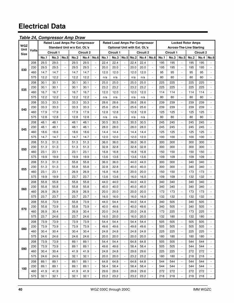
40 WGZ 030C through 200C IMM WGZC
Electrical Data
Table 24, Compressor Amp Draw Rated Load Amps Per Compressor Rated Load Amps Per Compressor Locked Rotor Amps
Standard Unit w/o Ext. OL's Optional Unit with Ext. OL's Across-The-Line Starting
Circuit 1 Circuit 2 Circuit 1 Circuit 2 Circuit 1 Circuit 2
WGZ Unit
Size Volts
No.1 No.3 No.5 No.2 No.4 No.6 No.1 No.3 No.5 No.2 No.4 No.6 No.1 No.3 No.5 No.2 No.4 No.6
208 29.5 29.5 - 29.5 29.5 - 22.4 22.4 - 22.4 22.4 - 195 195 - 195 195 -
230 29.5 29.5 - 29.5 29.5 - 20.0 20.0 - 20.0 20.0 - 195 195 - 195 195 -
460 14.7 14.7 - 14.7 14.7 - 12.0 12.0 - 12.0 12.0 - 95 95 - 95 95 - 030
575 12.2 12.2 - 12.2 12.2 - n/a n/a - n/a n/a - 80 80 - 80 80 -
208 30.1 30.1 - 30.1 30.1 - 25.0 25.0 - 25.0 25.0 - 225 225 - 225 225 -
230 30.1 30.1 - 30.1 30.1 - 23.2 23.2 - 23.2 23.2 - 225 225 - 225 225 -
460 16.7 16.7 - 16.7 16.7 - 12.0 12.0 - 12.0 12.0 - 114 114 - 114 114 - 035
575 12.2 12.2 - 12.2 12.2 - n/a n/a - n/a n/a - 80 80 - 80 80 -
208 33.3 33.3 - 33.3 33.3 - 28.6 28.6 - 28.6 28.6 - 239 239 - 239 239 -
230 33.3 33.3 - 33.3 33.3 - 25.6 25.6 - 25.6 25.6 - 239 239 - 239 239 -
460 17.9 17.9 - 17.9 17.9 - 12.8 12.8 - 12.8 12.8 - 125 125 - 125 125 - 040
575 12.8 12.8 - 12.8 12.8 - n/a n/a - n/a n/a - 80 80 - 80 80 -
208 48.1 48.1 - 48.1 48.1 - 30.5 30.5 - 30.5 30.5 - 245 245 - 245 245 -
230 48.1 48.1 - 48.1 48.1 - 28.0 28.0 - 28.0 28.0 - 245 245 - 245 245 -
460 18.6 18.6 - 18.6 18.6 - 14.4 14.4 - 14.4 14.4 - 125 125 - 125 125 - 045
575 14.7 14.7 - 14.7 14.7 - 12.0 12.0 - 12.0 12.0 - 100 100 - 100 100 -
208 51.3 51.3 - 51.3 51.3 - 36.0 36.0 - 36.0 36.0 - 300 300 - 300 300 -
230 51.3 51.3 - 51.3 51.3 - 32.8 32.8 - 32.8 32.8 - 300 300 - 300 300 -
460 23.1 23.1 - 23.1 23.1 - 16.8 16.8 - 16.8 16.8 - 150 150 - 150 150 - 050
575 19.9 19.9 - 19.9 19.9 - 13.6 13.6 - 13.6 13.6 - 109 109 - 109 109 -
208 51.3 51.3 - 55.8 55.8 - 36.0 36.0 - 44.0 44.0 - 300 300 - 340 340 -
230 51.3 51.3 - 55.8 55.8 - 32.8 32.8 - 40.0 40.0 - 300 300 - 340 340 -
460 23.1 23.1 - 26.9 26.9 - 16.8 16.8 - 20.0 20.0 - 150 150 - 173 173 - 055
575 19.9 19.9 - 23.7 23.7 - 13.6 13.6 - 16.0 16.0 - 109 109 - 132 132 -
208 55.8 55.8 - 55.8 55.8 - 44.0 44.0 - 44.0 44.0 - 340 340 - 340 340 -
230 55.8 55.8 - 55.8 55.8 - 40.0 40.0 - 40.0 40.0 - 340 340 - 340 340 -
460 26.9 26.9 - 26.9 26.9 - 20.0 20.0 - 20.0 20.0 - 173 173 - 173 173 - 060
575 23.7 23.7 - 23.7 23.7 - 16.0 16.0 - 16.0 16.0 - 132 132 - 132 132 -
208 55.8 73.9 - 55.8 73.9 - 44.0 54.4 - 44.0 54.4 - 340 505 - 340 505 -
230 55.8 73.9 - 55.8 73.9 - 40.0 49.6 - 40.0 49.6 - 340 505 - 340 505 -
460 26.9 30.4 - 26.9 30.4 - 20.0 24.8 - 20.0 24.8 - 173 225 - 173 225 - 070
575 23.7 24.6 - 23.7 24.6 - 16.0 20.0 - 16.0 20.0 - 132 180 - 132 180 -
208 73.9 73.9 - 73.9 73.9 - 54.4 54.4 - 54.4 54.4 - 505 505 - 505 505 -
230 73.9 73.9 - 73.9 73.9 - 49.6 49.6 - 49.6 49.6 - 505 505 - 505 505 -
460 30.4 30.4 - 30.4 30.4 - 24.8 24.8 - 24.8 24.8 - 225 225 - 225 225 - 080
575 24.6 24.6 - 24.6 24.6 - 20.0 20.0 - 20.0 20.0 - 180 180 - 180 180 -
208 73.9 73.9 - 89.1 89.1 - 54.4 54.4 - 64.8 64.8 - 505 505 - 544 544 -
230 73.9 73.9 - 89.1 89.1 - 49.6 49.6 - 58.4 58.4 - 505 505 - 544 544 -
460 30.4 30.4 - 41.9 41.9 - 24.8 24.8 - 29.6 29.6 - 225 225 - 272 272 - 090
575 24.6 24.6 - 32.1 32.1 - 20.0 20.0 - 23.2 23.2 - 180 180 - 218 218 -
208 89.1 89.1 - 89.1 89.1 - 64.8 64.8 - 64.8 64.8 - 544 544 - 544 544 -
230 89.1 89.1 - 89.1 89.1 - 58.4 58.4 - 58.4 58.4 - 544 544 - 544 544 -
460 41.9 41.9 - 41.9 41.9 - 29.6 29.6 - 29.6 29.6 - 272 272 - 272 272 - 100
575 32.1 32.1 - 32.1 32.1 - 23.2 23.2 - 23.2 23.2 - 218 218 - 218 218 -
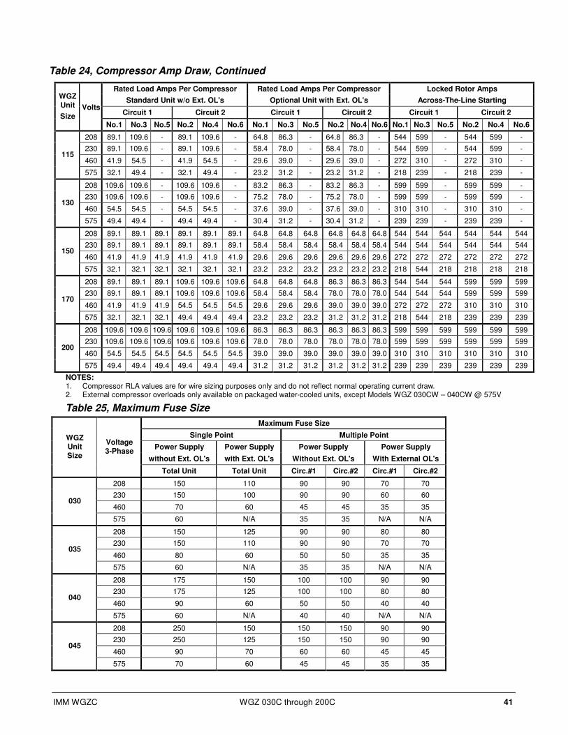
IMM WGZC WGZ 030C through 200C 41
Table 24, Compressor Amp Draw, Continued
Rated Load Amps Per Compressor Rated Load Amps Per Compressor Locked Rotor Amps
Standard Unit w/o Ext. OL's Optional Unit with Ext. OL's Across-The-Line Starting
Circuit 1 Circuit 2 Circuit 1 Circuit 2 Circuit 1 Circuit 2
WGZ Unit
Size Volts
No.1 No.3 No.5 No.2 No.4 No.6 No.1 No.3 No.5 No.2 No.4 No.6 No.1 No.3 No.5 No.2 No.4 No.6
208 89.1 109.6 - 89.1 109.6 - 64.8 86.3 - 64.8 86.3 - 544 599 - 544 599 -
230 89.1 109.6 - 89.1 109.6 - 58.4 78.0 - 58.4 78.0 - 544 599 - 544 599 -
460 41.9 54.5 - 41.9 54.5 - 29.6 39.0 - 29.6 39.0 - 272 310 - 272 310 - 115
575 32.1 49.4 - 32.1 49.4 - 23.2 31.2 - 23.2 31.2 - 218 239 - 218 239 -
208 109.6 109.6 - 109.6 109.6 - 83.2 86.3 - 83.2 86.3 - 599 599 - 599 599 -
230 109.6 109.6 - 109.6 109.6 - 75.2 78.0 - 75.2 78.0 - 599 599 - 599 599 -
460 54.5 54.5 - 54.5 54.5 - 37.6 39.0 - 37.6 39.0 - 310 310 - 310 310 - 130
575 49.4 49.4 - 49.4 49.4 - 30.4 31.2 - 30.4 31.2 - 239 239 - 239 239 -
208 89.1 89.1 89.1 89.1 89.1 89.1 64.8 64.8 64.8 64.8 64.8 64.8 544 544 544 544 544 544
230 89.1 89.1 89.1 89.1 89.1 89.1 58.4 58.4 58.4 58.4 58.4 58.4 544 544 544 544 544 544
460 41.9 41.9 41.9 41.9 41.9 41.9 29.6 29.6 29.6 29.6 29.6 29.6 272 272 272 272 272 272 150
575 32.1 32.1 32.1 32.1 32.1 32.1 23.2 23.2 23.2 23.2 23.2 23.2 218 544 218 218 218 218
208 89.1 89.1 89.1 109.6 109.6 109.6 64.8 64.8 64.8 86.3 86.3 86.3 544 544 544 599 599 599
230 89.1 89.1 89.1 109.6 109.6 109.6 58.4 58.4 58.4 78.0 78.0 78.0 544 544 544 599 599 599
460 41.9 41.9 41.9 54.5 54.5 54.5 29.6 29.6 29.6 39.0 39.0 39.0 272 272 272 310 310 310 170
575 32.1 32.1 32.1 49.4 49.4 49.4 23.2 23.2 23.2 31.2 31.2 31.2 218 544 218 239 239 239
208 109.6 109.6 109.6 109.6 109.6 109.6 86.3 86.3 86.3 86.3 86.3 86.3 599 599 599 599 599 599
230 109.6 109.6 109.6 109.6 109.6 109.6 78.0 78.0 78.0 78.0 78.0 78.0 599 599 599 599 599 599
460 54.5 54.5 54.5 54.5 54.5 54.5 39.0 39.0 39.0 39.0 39.0 39.0 310 310 310 310 310 310 200
575 49.4 49.4 49.4 49.4 49.4 49.4 31.2 31.2 31.2 31.2 31.2 31.2 239 239 239 239 239 239
NOTES: 1. Compressor RLA values are for wire sizing purposes only and do not reflect normal operating current draw. 2. External compressor overloads only available on packaged water-cooled units, except Models WGZ 030CW – 040CW @ 575V
Table 25, Maximum Fuse Size
Maximum Fuse Size
Single Point Multiple Point
Power Supply Power Supply Power Supply Power Supply
without Ext. OL's with Ext. OL's Without Ext. OL's With External OL's
WGZ Unit Size
Voltage 3-Phase
Total Unit Total Unit Circ.#1 Circ.#2 Circ.#1 Circ.#2
208 150 110 90 90 70 70
230 150 100 90 90 60 60
460 70 60 45 45 35 35 030
575 60 N/A 35 35 N/A N/A
208 150 125 90 90 80 80
230 150 110 90 90 70 70
460 80 60 50 50 35 35 035
575 60 N/A 35 35 N/A N/A
208 175 150 100 100 90 90
230 175 125 100 100 80 80
460 90 60 50 50 40 40 040
575 60 N/A 40 40 N/A N/A
208 250 150 150 150 90 90
230 250 125 150 150 90 90
460 90 70 60 60 45 45 045
575 70 60 45 45 35 35

WGZ 030C through 200C IMM WGZC
Table 25, Maximum Fuse Size, Continued
Single Point Multiple Point
Power Supply Power Supply Power Supply Power Supply
without Ext. OL's with Ext. OL's Without Ext. OL's With External OL's
WGZ
Unit Size
Voltage
3-Pha
Total Unit Total Unit Circ.#1 Circ.#2 Circ.#1 Circ.#2
208 250 175 150 150 110 110
230 250 150 150 150 100 100
460 110 80 70 70 50 50 050
575 100 70 60 60 40 40
208 250 200 150 175 115 125
230 250 175 150 175 100 125
460 125 90 70 80 50 60 055
575 110 70 60 70 40 50
208 250 225 175 175 125 125
230 250 200 175 175 125 125
460 125 100 80 80 60 60 060
575 110 80 70 70 50 50
208 350 250 200 200 150 150
230 350 225 200 200 150 150
460 150 110 90 90 70 70 070
575 125 90 70 70 60 60
208 350 250 225 225 175 175
230 350 250 225 225 150 150
460 150 125 90 90 80 80 080
575 125 100 80 80 60 60
208 400 300 225 250 175 200
230 400 250 225 250 150 175
460 175 125 90 125 80 90 090
575 150 110 80 100 60 70
208 450 300 250 250 200 200
230 450 300 250 250 175 175
460 200 150 125 125 90 90 100
575 150 110 100 100 70 70
208 500 400 300 300 250 250
230 500 350 300 300 225 225
460 250 175 150 150 110 110 115
575 200 125 125 125 90 90
208 500 400 350 350 250 250
230 500 350 350 350 250 250
460 250 175 175 175 125 125 130
575 250 150 150 150 100 90
208 600 450 350 350 250 250
230 600 400 350 350 225 225
460 300 200 175 175 125 125 150
575 225 150 125 125 90 90
208 700 500 350 450 250 350
230 700 450 350 450 225 300
460 350 225 175 225 125 150 170
575 300 175 125 200 90 125
208 700 600 450 450 350 350
230 700 500 450 450 300 300
460 350 250 225 225 150 150 200
575 350 200 200 200 125 125
NOTE :"Maximum Fuse Sizes" are selected at approximately 225% of the largest compressor RLA, plus 100% of all other loads.
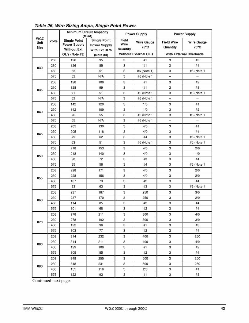
IMM WGZC WGZ 030C through 200C 43
Table 26, Wire Sizing Amps, Single Point Power
Minimum Circuit Ampacity (MCA)
Power Supply Power Supply
Field Wire
Quantity
Wire Gauge
75°°°°C
Field Wire
Quantity
Wire Gauge
75°°°°C
WGZ Unit
Size
Volts Single Point Power Supply
Without Ext
OL's (Note #3)
Single Point
Power Supply
With Ext OL's
(Note #3) Without External OL's With External Overloads
208 126 95 3 #1 3 #3
230 126 85 3 #1 3 #4
460 63 51 3 #6 (Note 1) 3 #6 (Note 1 030
575 52 N/A 3 #6 (Note 1 -- --
208 128 106 3 #1 3 #2
230 128 99 3 #1 3 #3
460 71 51 3 #6 (Note 1 3 #6 (Note 1 035
575 52 N/A 3 #6 (Note 1 -- --
208 142 120 3 1/0 3 #1
230 142 109 3 1/0 3 #2
460 76 55 3 #6 (Note 1 3 #6 (Note 1 040
575 55 N/A 3 #6 (Note 1 -- --
208 205 130 3 4/0 3 #1
230 205 118 3 4/0 3 #1
460 79 62 3 #4 3 #6 (Note 1 045
575 63 51 3 #6 (Note 1 3 #6 (Note 1
208 218 153 3 4/0 3 2/0
230 218 140 3 4/0 3 1/0
460 98 72 3 #3 3 #4 050
575 85 58 3 #4 3 #6 (Note 1
208 228 171 3 4/0 3 2/0
230 228 156 3 4/0 3 2/0
460 107 79 3 #2 3 #4 055
575 93 63 3 #3 3 #6 (Note 1
208 237 187 3 250 3 3/0
230 237 170 3 250 3 2/0
460 114 85 3 #2 3 #4 060
575 101 68 3 #2 3 #4
208 278 211 3 300 3 4/0
230 278 192 3 300 3 3/0
460 122 96 3 #1 3 #3 070
575 103 77 3 #2 3 #4
208 314 232 3 400 3 250
230 314 211 3 400 3 4/0
460 129 106 3 #1 3 #2 080
575 105 85 3 #2 3 #4
208 348 255 3 500 3 250
230 348 231 3 500 3 250
460 155 116 3 2/0 3 #1 090
575 122 92 3 #1 3 #3
Continued next page.
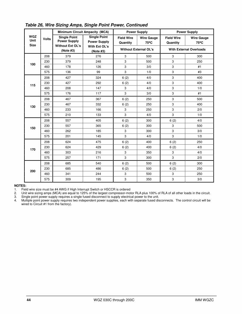
44 WGZ 030C through 200C IMM WGZC
Table 26, Wire Sizing Amps, Single Point Power, Continued
Minimum Circuit Ampacity (MCA) Power Supply Power Supply
Field Wire
Quantity
Wire Gauge
75°°°°C
Field Wire
Quantity
Wire Gauge
75°°°°C
WGZ Unit
Size
Volts Single Point
Power Supply
Without Ext OL's
(Note #3)
Single Point
Power Supply
With Ext OL's
(Note #3) Without External OL's With External Overloads
208 379 276 3 500 3 300
230 379 248 3 500 3 250
460 178 126 3 3/0 3 #1 100
575 136 99 3 1/0 3 #3
208 427 324 6 (2) 4/0 3 400
230 427 292 6 (2) 4/0 3 400
460 208 147 3 4/0 3 1/0 115
575 176 117 3 3/0 3 #1
208 467 367 6 (2) 250 3 500
230 467 332 6 (2) 250 3 400
460 233 166 3 250 3 2/0 130
575 210 133 3 4/0 3 1/0
208 557 405 6 (2) 300 6 (2) 4/0
230 557 365 6 (2) 300 3 500
460 262 185 3 300 3 3/0 150
575 201 145 3 4/0 3 1/0
208 624 475 6 (2) 400 6 (2) 250
230 624 429 6 (2) 400 6 (2) 4/0
460 303 216 3 350 3 4/0 170
575 257 171 3 300 3 2/0
208 685 540 6 (2) 500 6 (2) 300
230 685 486 6 (2) 500 6 (2) 250
460 341 244 3 500 3 250 200
575 309 195 3 350 3 3/0
NOTES: 1. Field wire size must be #4 AWG if High Interrupt Switch or HSCCR is ordered 2. Unit wire sizing amps (MCA) are equal to 125% of the largest compressor-motor RLA plus 100% of RLA of all other loads in the circuit. 3. Single point power supply requires a single fused disconnect to supply electrical power to the unit. 4. Multiple point power supply requires two independent power supplies, each with separate fused disconnects. The control circuit will be
wired to Circuit #1 from the factory).

IMM WGZC WGZ 030C through 200C 45
Table 27, Wire Sizing, Multi-point Power
Minimum Circuit Ampacity (MCA) Power Supply
Without External OL's Power Supply
With External OL's
Without Ext OL's With External OL's Wire Gauge, 75C Wire Gauge,75C
WGZ Unit Size
Volts
Circuit No.1
Circuit No.2
Circuit No.1
Circuit No.2
Field Wire
Quantity Circuit No.1
Circuit No.2
Field Wire
Quantity Circuit No.1
Circuit No.2
208 67 67 51 51 3 #4 #4 3 #6 #6
230 67 67 45 45 3 #4 #4 3 #8 #8
460 33 33 27 27 3 #10 #10 3 #10 #10 030
575 28 28 N/A N/A 3 #10 #10 3 -- --
208 68 68 57 57 3 #4 #4 3 #6 #6
230 68 68 53 53 3 #4 #4 3 #6 #6
460 38 38 27 27 3 #8 #8 3 #10 #10 035
575 28 28 N/A N/A 3 #10 #10 3 -- --
208 75 75 65 65 3 #4 #4 3 #6 #6
230 75 75 58 58 3 #4 #4 3 #6 #6
460 41 41 29 29 3 #8 #8 3 #10 #10 040
575 29 29 N/A N/A 3 #10 #10 3 -- --
208 109 109 69 69 3 #2 #2 3 #4 #4
230 109 109 63 63 3 #2 #2 3 #6 #6
460 42 42 33 33 3 #8 #8 3 #10 #10 045
575 33 33 27 27 3 #10 #10 3 #10 #10
208 116 116 81 81 3 #1 #1 3 #4 #4
230 116 116 74 74 3 #1 #1 3 #4 #4
460 52 52 38 38 3 #6 #6 3 #8 #8 050
575 45 45 31 31 3 #8 #8 3 #10 #10
208 116 126 81 99 3 #1 #1 3 #4 #3
230 116 126 74 90 3 #1 #1 3 #4 #3
460 52 61 38 45 3 #6 #6 3 #8 #8 055
575 45 54 31 36 3 #8 #6 3 #10 #8
208 126 126 99 99 3 #1 #1 3 #3 #3
230 126 126 90 90 3 #1 #1 3 #3 #3
460 61 61 45 45 3 #6 #6 3 #8 #8 060
575 54 54 36 36 3 #6 #6 3 #8 #8
208 149 149 112 112 3 1/0 1/0 3 #2 #2
230 149 149 102 102 3 1/0 1/0 3 #2 #2
460 65 65 51 51 3 #6 #6 3 #6 #6 070
575 55 55 41 41 3 #6 #6 3 #8 #8
208 167 167 123 123 3 2/0 2/0 3 #1 #1
230 167 167 112 112 3 2/0 2/0 3 #2 #2
460 69 69 56 56 3 #4 #4 3 #6 #6 080
575 56 56 45 45 3 #6 #6 3 #8 #8
208 167 201 123 146 3 2/0 4/0 3 #1 1/0
230 167 201 112 132 3 2/0 4/0 3 #2 1/0
460 69 95 56 67 3 #4 #3 3 #6 #4 090
575 56 73 45 53 3 #6 #4 3 #8 #6
208 201 201 146 146 3 4/0 4/0 3 1/0 1/0
230 201 201 132 132 3 4/0 4/0 3 1/0 1/0
460 95 95 67 67 3 #3 #3 3 #4 #4 100
575 73 73 53 53 3 #4 #4 3 #6 #6
208 227 227 173 173 3 4/0 4/0 3 2/0 2/0
230 227 227 156 156 3 4/0 4/0 3 2/0 2/0
460 111 111 79 79 3 #2 #2 3 #4 #4 115
575 94 94 63 63 3 #3 #3 3 #6 #6
Continued next page.
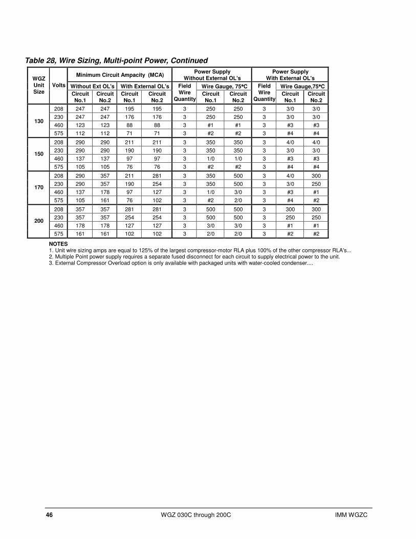
46 WGZ 030C through 200C IMM WGZC
Table 28, Wire Sizing, Multi-point Power, Continued
Minimum Circuit Ampacity (MCA) Power Supply
Without External OL's Power Supply
With External OL's
Without Ext OL's With External OL's Wire Gauge, 75°°°°C Wire Gauge,75°°°°C
WGZ Unit Size
Volts
Circuit No.1
Circuit No.2
Circuit No.1
Circuit No.2
Field Wire
Quantity Circuit No.1
Circuit No.2
Field Wire
Quantity Circuit No.1
Circuit No.2
208 247 247 195 195 3 250 250 3 3/0 3/0
230 247 247 176 176 3 250 250 3 3/0 3/0
460 123 123 88 88 3 #1 #1 3 #3 #3 130
575 112 112 71 71 3 #2 #2 3 #4 #4
208 290 290 211 211 3 350 350 3 4/0 4/0
230 290 290 190 190 3 350 350 3 3/0 3/0
460 137 137 97 97 3 1/0 1/0 3 #3 #3 150
575 105 105 76 76 3 #2 #2 3 #4 #4
208 290 357 211 281 3 350 500 3 4/0 300
230 290 357 190 254 3 350 500 3 3/0 250
460 137 178 97 127 3 1/0 3/0 3 #3 #1 170
575 105 161 76 102 3 #2 2/0 3 #4 #2
208 357 357 281 281 3 500 500 3 300 300
230 357 357 254 254 3 500 500 3 250 250
460 178 178 127 127 3 3/0 3/0 3 #1 #1 200
575 161 161 102 102 3 2/0 2/0 3 #2 #2
NOTES 1. Unit wire sizing amps are equal to 125% of the largest compressor-motor RLA plus 100% of the other compressor RLA's... 2. Multiple Point power supply requires a separate fused disconnect for each circuit to supply electrical power to the unit. 3. External Compressor Overload option is only available with packaged units with water-cooled condenser....
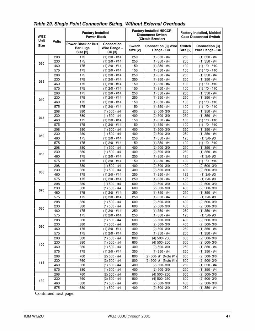
IMM WGZC WGZ 030C through 200C 47
Table 29, Single Point Connection Sizing, Without External Overloads
Factory-Installed Power Block
Factory-Installed HSCCR Disconnect Switch (Circuit Breaker)
Factory-Installed, Molded Case Disconnect Switch WGZ
Unit
Size Volts
Power Block or Bus Bar Lugs Size [2]
Connection Wire Range –
CU [3]
Switch Size [2]
Connection [3] Wire Range - CU
Switch Size [2]
Connection [3] Wire Range - CU
208 175 (1) 2/0 - #14 250 (1) 350 - #4 250 (1) 350 - #4
230 175 (1) 2/0 - #14 250 (1) 350 - #4 250 (1) 350 - #4
460 175 (1) 2/0 - #14 150 (1) 350 - #4 100 (1) 1/0 - #10 030
575 175 (1) 2/0 - #14 150 (1) 350 - #4 100 (1) 1/0 - #10
208 175 (1) 2/0 - #14 250 (1) 350 - #4 250 (1) 350 - #4
230 175 (1) 2/0 - #14 250 (1) 350 - #4 250 (1) 350 - #4
460 175 (1) 2/0 - #14 150 (1) 350 - #4 100 (1) 1/0 - #10 035
575 175 (1) 2/0 - #14 150 (1) 350 - #4 100 (1) 1/0 - #10
208 175 (1) 2/0 - #14 250 (1) 350 - #4 250 (1) 350 - #4
230 175 (1) 2/0 - #14 250 (1) 350 - #4 250 (1) 350 - #4
460 175 (1) 2/0 - #14 150 (1) 350 - #4 100 (1) 1/0 - #10 040
575 175 (1) 2/0 - #14 150 (1) 350 - #4 100 (1) 1/0 - #10
208 380 (1) 500 - #4 400 (2) 500- 3/0 250 (1) 350 - #4
230 380 (1) 500 - #4 400 (2) 500- 3/0 250 (1) 350 - #4
460 175 (1) 2/0 - #14 150 (1) 350 - #4 100 (1) 1/0 - #10 045
575 175 (1) 2/0 - #14 150 (1) 350 - #4 100 (1) 1/0 - #10
208 380 (1) 500 - #4 400 (2) 500- 3/0 250 (1) 350 - #4
230 380 (1) 500 - #4 400 (2) 500- 3/0 250 (1) 350 - #4
460 175 (1) 2/0 - #14 250 (1) 350 - #4 125 (1) 3/0- #3 050
575 175 (1) 2/0 - #14 150 (1) 350 - #4 100 (1) 1/0 - #10
208 380 (1) 500 - #4 400 (2) 500- 3/0 250 (1) 350 - #4
230 380 (1) 500 - #4 400 (2) 500- 3/0 250 (1) 350 - #4
460 175 (1) 2/0 - #14 250 (1) 350 - #4 125 (1) 3/0- #3 055
575 175 (1) 2/0 - #14 150 (1) 350 - #4 100 (1) 1/0 - #10
208 380 (1) 500 - #4 400 (2) 500- 3/0 400 (2) 500- 3/0
230 380 (1) 500 - #4 400 (2) 500- 3/0 400 (2) 500- 3/0
460 175 (1) 2/0 - #14 250 (1) 350 - #4 125 (1) 3/0- #3 060
575 175 (1) 2/0 - #14 250 (1) 350 - #4 125 (1) 3/0- #3
208 380 (1) 500 - #4 600 (2) 500- 3/0 400 (2) 500- 3/0
230 380 (1) 500 - #4 600 (2) 500- 3/0 400 (2) 500- 3/0
460 175 (1) 2/0 - #14 250 (1) 350 - #4 250 (1) 350 - #4 070
575 175 (1) 2/0 - #14 250 (1) 350 - #4 125 (1) 3/0- #3
208 380 (1) 500 - #4 600 (2) 500- 3/0 400 (2) 500- 3/0
230 380 (1) 500 - #4 600 (2) 500- 3/0 400 (2) 500- 3/0
460 175 (1) 2/0 - #14 250 (1) 350 - #4 250 (1) 350 - #4 080
575 175 (1) 2/0 - #14 250 (1) 350 - #4 125 (1) 3/0- #3
208 380 (1) 500 - #4 600 (2) 500- 3/0 400 (2) 500- 3/0
230 380 (1) 500 - #4 600 (2) 500- 3/0 400 (2) 500- 3/0
460 175 (1) 2/0 - #14 400 (2) 500- 3/0 250 (1) 350 - #4 090
575 175 (1) 2/0 - #14 250 (1) 350 - #4 250 (1) 350 - #4
208 380 (1) 500 - #4 800 (4) 500- 250 600 (2) 500- 3/0
230 380 (1) 500 - #4 800 (4) 500- 250 600 (2) 500- 3/0
460 380 (1) 500 - #4 400 (2) 500- 3/0 250 (1) 350 - #4 100
575 175 (1) 2/0 - #14 250 (1) 350 - #4 250 (1) 350 - #4
208 760 (2) 500 - #4 800 (2) 500- #1 (Note #1) 600 (2) 500- 3/0
230 760 (2) 500 - #4 800 (2) 500- #1 (Note #1) 600 (2) 500- 3/0
460 380 (1) 500 - #4 400 (2) 500- 3/0 250 (1) 350 - #4 115
575 380 (1) 500 - #4 400 (2) 500- 3/0 250 (1) 350 - #4
208 760 (2) 500 - #4 800 (4) 500- 250 600 (2) 500- 3/0
230 760 (2) 500 - #4 800 (4) 500- 250 600 (2) 500- 3/0
460 380 (1) 500 - #4 400 (2) 500- 3/0 400 (2) 500- 3/0 130
575 380 (1) 500 - #4 400 (2) 500- 3/0 250 (1) 350 - #4
Continued next page.
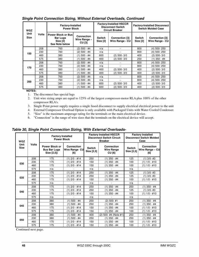
48 WGZ 030C through 200C IMM WGZC
Single Point Connection Sizing, Without External Overloads, Continued
Factory-Installed Power Block
Factory-Installed HSCCR Disconnect Switch
Circuit Breaker
Factory-Installed Disconnect Switch Molded Case
WGZ Unit
Size Volts Power Block or Bus
Bar Lugs Size [2]
See Note below
Connection Wire Range –
CU [3]
Switch Size [2]
Connection [3] Wire Range - CU
Switch Size [2]
Connection [3] Wire Range - CU
208 760 (2) 500 - #4 n/a -- 800 (4) 500- 250
230 760 (2) 500 - #4 n/a -- 800 (4) 500- 250
460 380 (1) 500 - #4 600 (2) 500- 3/0 400 (2) 500- 3/0 150
575 380 (1) 500 - #4 400 (2) 500- 3/0 250 (1) 350 - #4
208 760 (2) 500 - #4 n/a -- 800 (4) 500- 250
230 760 (2) 500 - #4 n/a -- 800 (4) 500- 250
460 380 (1) 500 - #4 400 (2) 500- 3/0 400 (2) 500- 3/0 170
575 380 (1) 500 - #4 400 (2) 500- 3/0 400 (2) 500- 3/0
208 760 (2) 500 - #4 n/a -- 800 (4) 500- 250
230 760 (2) 500 - #4 n/a -- 800 (4) 500- 250
460 380 (1) 500 - #4 600 (2) 500- 3/0 400 (2) 500- 3/0 200
575 380 (1) 500 - #4 600 (2) 500- 3/0 400 (2) 500- 3/0
NOTES:
1. The disconnect has special lugs
2. Unit wire sizing amps are equal to 125% of the largest compressor-motor RLA plus 100% of the other
compressor RLA's.
3. Single Point power supply requires a single fused disconnect to supply electrical electrical power to the unit
4. External Compressor Overload Option is only available with Packaged Units with Water Cooled Condenser.
5. “Size" is the maximum amperage rating for the terminals or the main electrical device.
6. "Connection" is the range of wire sizes that the terminals on the electrical device will accept.
Table 30, Single Point Connection Sizing, With External Overloads-
Factory Installed Power Block
Factory Installed HSCCR Disconnect Switch Circuit
Breaker
Factory Installed Disconnect Switch Molded
Case WGZ Unit Size
Volts Power Block or Bus Bar Lugs
Size [2,5])
Connection Wire Range CU
[6]
Switch Size [2,5]
Connection Wire Range
CU [6]
Switch Size [2,5]
Connection Wire Range – CU
[6]
208 175 (1) 2/0 - #14 250 (1) 350 - #4 125 (1) 3/0- #3
230 175 (1) 2/0 - #14 150 (1) 350 - #4 100 (1) 1/0 - #10
460 175 (1) 2/0 - #14 150 (1) 350 - #4 100 (1) 1/0 - #10 030
575 n/a - n/a - n/a -
208 175 (1) 2/0 - #14 250 (1) 350 - #4 125 (1) 3/0- #3
230 175 (1) 2/0 - #14 250 (1) 350 - #4 125 (1) 3/0- #3
460 175 (1) 2/0 - #14 150 (1) 350 - #4 100 (1) 1/0 - #10 035
575 n/a - n/a - n/a -
208 175 (1) 2/0 - #14 250 (1) 350 - #4 250 (1) 350 - #4
230 175 (1) 2/0 - #14 250 (1) 350 - #4 125 (1) 3/0- #3
460 175 (1) 2/0 - #14 150 (1) 350 - #4 100 (1) 1/0 - #10 040
575 n/a - n/a - n/a -
208 380 (1) 500 - #4 250 (2) 500- #1 250 (1) 350 - #4
230 380 (1) 500 - #4 250 (1) 350 - #4 250 (1) 350 - #4
460 175 (1) 2/0 - #14 150 (1) 350 - #4 100 (1) 1/0 - #10 045
575 175 (1) 2/0 - #14 150 (1) 350 - #4 100 (1) 1/0 - #10
208 380 (1) 500 - #4 400 (2) 500- #4 (Note #1) 250 (1) 350 - #4
230 380 (1) 500 - #4 250 (1) 350 - #4 250 (1) 350 - #4
460 175 (1) 2/0 - #14 150 (1) 350 - #4 100 (1) 1/0 - #10 050
575 175 (1) 2/0 - #14 150 (1) 350 - #4 100 (1) 1/0 - #10
Continued next page.
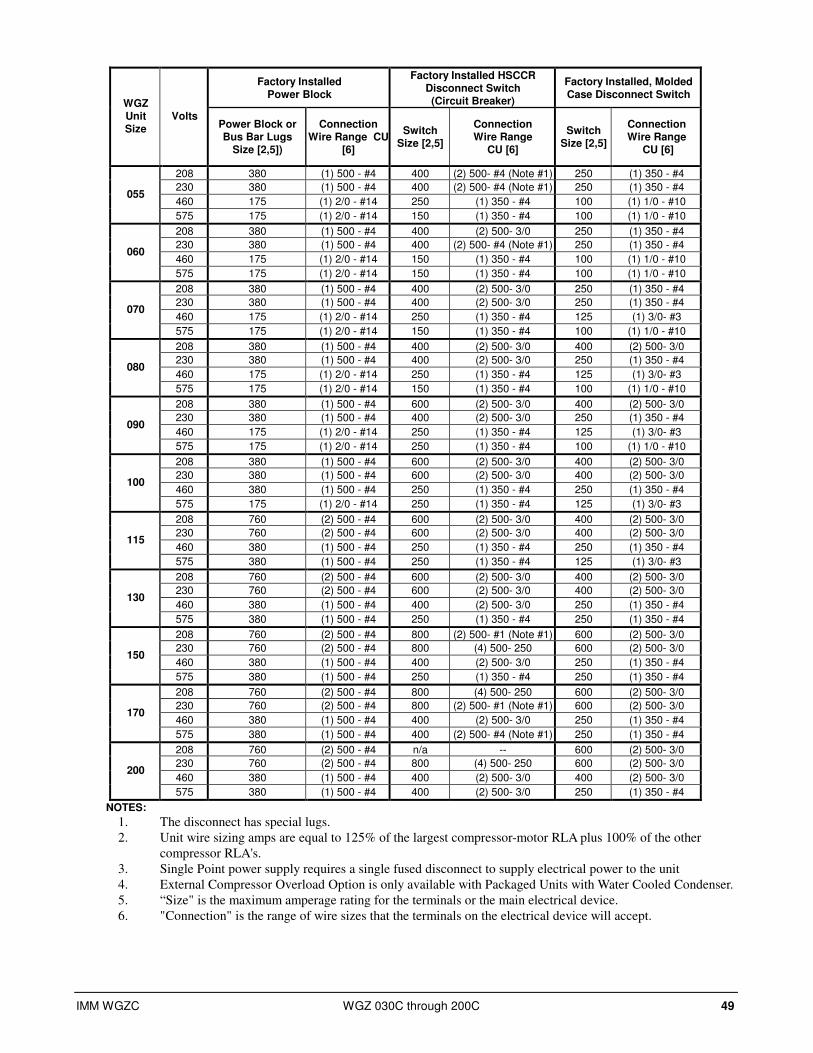
IMM WGZC WGZ 030C through 200C 49
Factory Installed Power Block
Factory Installed HSCCR Disconnect Switch (Circuit Breaker)
Factory Installed, Molded Case Disconnect Switch
WGZ Unit Size
Volts Power Block or Bus Bar Lugs
Size [2,5])
Connection Wire Range CU
[6]
Switch Size [2,5]
Connection Wire Range
CU [6]
Switch Size [2,5]
Connection Wire Range
CU [6]
208 380 (1) 500 - #4 400 (2) 500- #4 (Note #1) 250 (1) 350 - #4
230 380 (1) 500 - #4 400 (2) 500- #4 (Note #1) 250 (1) 350 - #4
460 175 (1) 2/0 - #14 250 (1) 350 - #4 100 (1) 1/0 - #10 055
575 175 (1) 2/0 - #14 150 (1) 350 - #4 100 (1) 1/0 - #10
208 380 (1) 500 - #4 400 (2) 500- 3/0 250 (1) 350 - #4
230 380 (1) 500 - #4 400 (2) 500- #4 (Note #1) 250 (1) 350 - #4
460 175 (1) 2/0 - #14 150 (1) 350 - #4 100 (1) 1/0 - #10 060
575 175 (1) 2/0 - #14 150 (1) 350 - #4 100 (1) 1/0 - #10
208 380 (1) 500 - #4 400 (2) 500- 3/0 250 (1) 350 - #4
230 380 (1) 500 - #4 400 (2) 500- 3/0 250 (1) 350 - #4
460 175 (1) 2/0 - #14 250 (1) 350 - #4 125 (1) 3/0- #3 070
575 175 (1) 2/0 - #14 150 (1) 350 - #4 100 (1) 1/0 - #10
208 380 (1) 500 - #4 400 (2) 500- 3/0 400 (2) 500- 3/0
230 380 (1) 500 - #4 400 (2) 500- 3/0 250 (1) 350 - #4
460 175 (1) 2/0 - #14 250 (1) 350 - #4 125 (1) 3/0- #3 080
575 175 (1) 2/0 - #14 150 (1) 350 - #4 100 (1) 1/0 - #10
208 380 (1) 500 - #4 600 (2) 500- 3/0 400 (2) 500- 3/0
230 380 (1) 500 - #4 400 (2) 500- 3/0 250 (1) 350 - #4
460 175 (1) 2/0 - #14 250 (1) 350 - #4 125 (1) 3/0- #3 090
575 175 (1) 2/0 - #14 250 (1) 350 - #4 100 (1) 1/0 - #10
208 380 (1) 500 - #4 600 (2) 500- 3/0 400 (2) 500- 3/0
230 380 (1) 500 - #4 600 (2) 500- 3/0 400 (2) 500- 3/0
460 380 (1) 500 - #4 250 (1) 350 - #4 250 (1) 350 - #4 100
575 175 (1) 2/0 - #14 250 (1) 350 - #4 125 (1) 3/0- #3
208 760 (2) 500 - #4 600 (2) 500- 3/0 400 (2) 500- 3/0
230 760 (2) 500 - #4 600 (2) 500- 3/0 400 (2) 500- 3/0
460 380 (1) 500 - #4 250 (1) 350 - #4 250 (1) 350 - #4 115
575 380 (1) 500 - #4 250 (1) 350 - #4 125 (1) 3/0- #3
208 760 (2) 500 - #4 600 (2) 500- 3/0 400 (2) 500- 3/0
230 760 (2) 500 - #4 600 (2) 500- 3/0 400 (2) 500- 3/0
460 380 (1) 500 - #4 400 (2) 500- 3/0 250 (1) 350 - #4 130
575 380 (1) 500 - #4 250 (1) 350 - #4 250 (1) 350 - #4
208 760 (2) 500 - #4 800 (2) 500- #1 (Note #1) 600 (2) 500- 3/0
230 760 (2) 500 - #4 800 (4) 500- 250 600 (2) 500- 3/0
460 380 (1) 500 - #4 400 (2) 500- 3/0 250 (1) 350 - #4 150
575 380 (1) 500 - #4 250 (1) 350 - #4 250 (1) 350 - #4
208 760 (2) 500 - #4 800 (4) 500- 250 600 (2) 500- 3/0
230 760 (2) 500 - #4 800 (2) 500- #1 (Note #1) 600 (2) 500- 3/0
460 380 (1) 500 - #4 400 (2) 500- 3/0 250 (1) 350 - #4 170
575 380 (1) 500 - #4 400 (2) 500- #4 (Note #1) 250 (1) 350 - #4
208 760 (2) 500 - #4 n/a -- 600 (2) 500- 3/0
230 760 (2) 500 - #4 800 (4) 500- 250 600 (2) 500- 3/0
460 380 (1) 500 - #4 400 (2) 500- 3/0 400 (2) 500- 3/0 200
575 380 (1) 500 - #4 400 (2) 500- 3/0 250 (1) 350 - #4
NOTES:
1. The disconnect has special lugs.
2. Unit wire sizing amps are equal to 125% of the largest compressor-motor RLA plus 100% of the other
compressor RLA's.
3. Single Point power supply requires a single fused disconnect to supply electrical power to the unit
4. External Compressor Overload Option is only available with Packaged Units with Water Cooled Condenser.
5. “Size" is the maximum amperage rating for the terminals or the main electrical device.
6. "Connection" is the range of wire sizes that the terminals on the electrical device will accept.
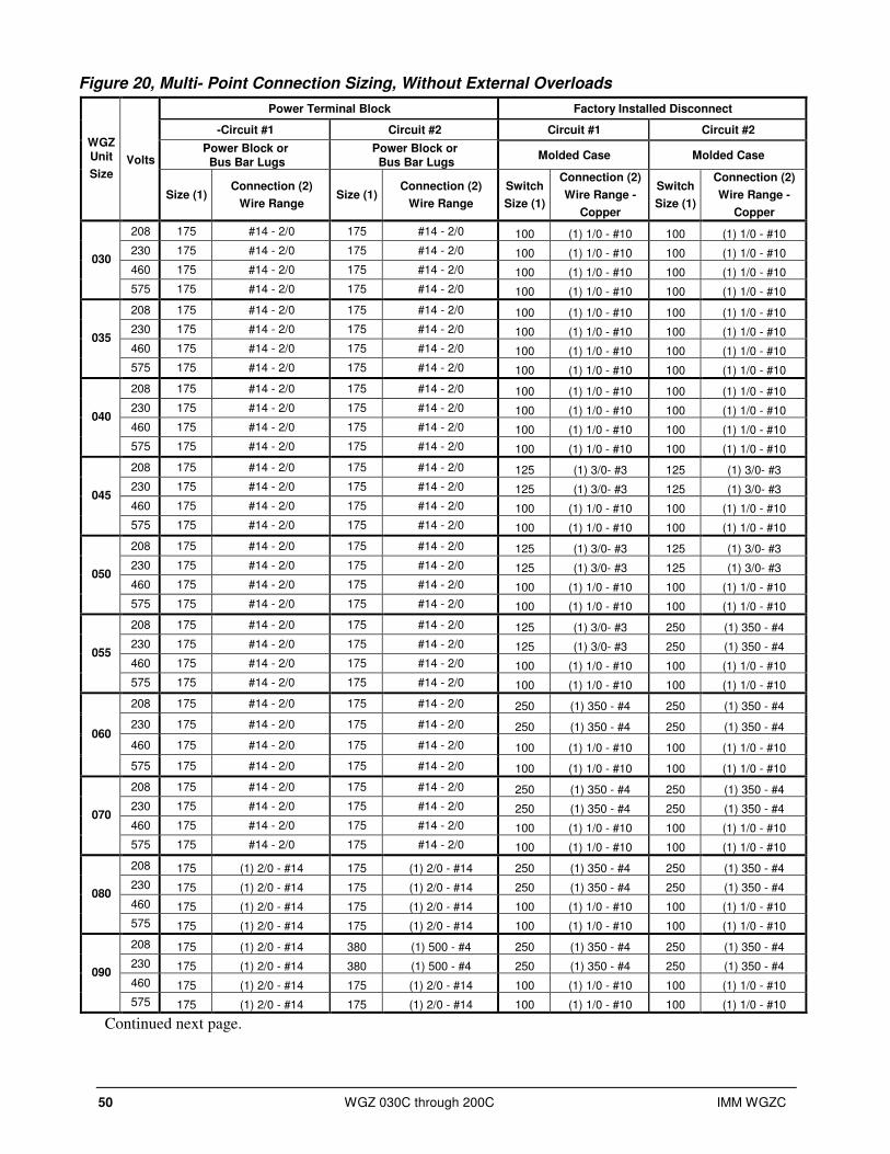
50 WGZ 030C through 200C IMM WGZC
Figure 20, Multi- Point Connection Sizing, Without External Overloads
Power Terminal Block Factory Installed Disconnect
-Circuit #1 Circuit #2 Circuit #1 Circuit #2
Power Block or Bus Bar Lugs
Power Block or Bus Bar Lugs
Molded Case Molded Case WGZ Unit
Size Volts
Size (1) Connection (2)
Wire Range Size (1)
Connection (2)
Wire Range
Switch
Size (1)
Connection (2)
Wire Range -
Copper
Switch
Size (1)
Connection (2)
Wire Range -
Copper
208 175 #14 - 2/0 175 #14 - 2/0 100 (1) 1/0 - #10 100 (1) 1/0 - #10
230 175 #14 - 2/0 175 #14 - 2/0 100 (1) 1/0 - #10 100 (1) 1/0 - #10
460 175 #14 - 2/0 175 #14 - 2/0 100 (1) 1/0 - #10 100 (1) 1/0 - #10 030
575 175 #14 - 2/0 175 #14 - 2/0 100 (1) 1/0 - #10 100 (1) 1/0 - #10
208 175 #14 - 2/0 175 #14 - 2/0 100 (1) 1/0 - #10 100 (1) 1/0 - #10
230 175 #14 - 2/0 175 #14 - 2/0 100 (1) 1/0 - #10 100 (1) 1/0 - #10
460 175 #14 - 2/0 175 #14 - 2/0 100 (1) 1/0 - #10 100 (1) 1/0 - #10 035
575 175 #14 - 2/0 175 #14 - 2/0 100 (1) 1/0 - #10 100 (1) 1/0 - #10
208 175 #14 - 2/0 175 #14 - 2/0 100 (1) 1/0 - #10 100 (1) 1/0 - #10
230 175 #14 - 2/0 175 #14 - 2/0 100 (1) 1/0 - #10 100 (1) 1/0 - #10
460 175 #14 - 2/0 175 #14 - 2/0 100 (1) 1/0 - #10 100 (1) 1/0 - #10 040
575 175 #14 - 2/0 175 #14 - 2/0 100 (1) 1/0 - #10 100 (1) 1/0 - #10
208 175 #14 - 2/0 175 #14 - 2/0 125 (1) 3/0- #3 125 (1) 3/0- #3
230 175 #14 - 2/0 175 #14 - 2/0 125 (1) 3/0- #3 125 (1) 3/0- #3
460 175 #14 - 2/0 175 #14 - 2/0 100 (1) 1/0 - #10 100 (1) 1/0 - #10 045
575 175 #14 - 2/0 175 #14 - 2/0 100 (1) 1/0 - #10 100 (1) 1/0 - #10
208 175 #14 - 2/0 175 #14 - 2/0 125 (1) 3/0- #3 125 (1) 3/0- #3
230 175 #14 - 2/0 175 #14 - 2/0 125 (1) 3/0- #3 125 (1) 3/0- #3
460 175 #14 - 2/0 175 #14 - 2/0 100 (1) 1/0 - #10 100 (1) 1/0 - #10 050
575 175 #14 - 2/0 175 #14 - 2/0 100 (1) 1/0 - #10 100 (1) 1/0 - #10
208 175 #14 - 2/0 175 #14 - 2/0 125 (1) 3/0- #3 250 (1) 350 - #4
230 175 #14 - 2/0 175 #14 - 2/0 125 (1) 3/0- #3 250 (1) 350 - #4
460 175 #14 - 2/0 175 #14 - 2/0 100 (1) 1/0 - #10 100 (1) 1/0 - #10 055
575 175 #14 - 2/0 175 #14 - 2/0 100 (1) 1/0 - #10 100 (1) 1/0 - #10
208 175 #14 - 2/0 175 #14 - 2/0 250 (1) 350 - #4 250 (1) 350 - #4
230 175 #14 - 2/0 175 #14 - 2/0 250 (1) 350 - #4 250 (1) 350 - #4
460 175 #14 - 2/0 175 #14 - 2/0 100 (1) 1/0 - #10 100 (1) 1/0 - #10 060
575 175 #14 - 2/0 175 #14 - 2/0 100 (1) 1/0 - #10 100 (1) 1/0 - #10
208 175 #14 - 2/0 175 #14 - 2/0 250 (1) 350 - #4 250 (1) 350 - #4
230 175 #14 - 2/0 175 #14 - 2/0 250 (1) 350 - #4 250 (1) 350 - #4
460 175 #14 - 2/0 175 #14 - 2/0 100 (1) 1/0 - #10 100 (1) 1/0 - #10 070
575 175 #14 - 2/0 175 #14 - 2/0 100 (1) 1/0 - #10 100 (1) 1/0 - #10
208 175 (1) 2/0 - #14 175 (1) 2/0 - #14 250 (1) 350 - #4 250 (1) 350 - #4
230 175 (1) 2/0 - #14 175 (1) 2/0 - #14 250 (1) 350 - #4 250 (1) 350 - #4
460 175 (1) 2/0 - #14 175 (1) 2/0 - #14 100 (1) 1/0 - #10 100 (1) 1/0 - #10 080
575 175 (1) 2/0 - #14 175 (1) 2/0 - #14 100 (1) 1/0 - #10 100 (1) 1/0 - #10
208 175 (1) 2/0 - #14 380 (1) 500 - #4 250 (1) 350 - #4 250 (1) 350 - #4
230 175 (1) 2/0 - #14 380 (1) 500 - #4 250 (1) 350 - #4 250 (1) 350 - #4
460 175 (1) 2/0 - #14 175 (1) 2/0 - #14 100 (1) 1/0 - #10 100 (1) 1/0 - #10 090
575 175 (1) 2/0 - #14 175 (1) 2/0 - #14 100 (1) 1/0 - #10 100 (1) 1/0 - #10
Continued next page.
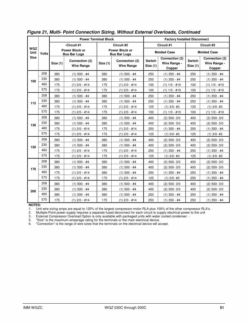
IMM WGZC WGZ 030C through 200C 51
Figure 21, Multi- Point Connection Sizing, Without External Overloads, Continued
Power Terminal Block Factory Installed Disconnect
-Circuit #1 Circuit #2 Circuit #1 Circuit #2
Power Block or Bus Bar Lugs
Power Block or Bus Bar Lugs
Molded Case Molded Case WGZ Unit
Size Volts
Size (1) Connection (2)
Wire Range Size (1)
Connection (2)
Wire Range
Switch
Size (1)
Connection (2)
Wire Range -
Copper
Switch
Size (1)
Connection (2)
Wire Range -
Copper
208 380 (1) 500 - #4 380 (1) 500 - #4 250 (1) 350 - #4 250 (1) 350 - #4
230 380 (1) 500 - #4 380 (1) 500 - #4 250 (1) 350 - #4 250 (1) 350 - #4
460 175 (1) 2/0 - #14 175 (1) 2/0 - #14 100 (1) 1/0 - #10 100 (1) 1/0 - #10 100
575 175 (1) 2/0 - #14 175 (1) 2/0 - #14 100 (1) 1/0 - #10 100 (1) 1/0 - #10
208 380 (1) 500 - #4 380 (1) 500 - #4 250 (1) 350 - #4 250 (1) 350 - #4
230 380 (1) 500 - #4 380 (1) 500 - #4 250 (1) 350 - #4 250 (1) 350 - #4
460 175 (1) 2/0 - #14 175 (1) 2/0 - #14 125 (1) 3/0- #3 125 (1) 3/0- #3 115
575 175 (1) 2/0 - #14 175 (1) 2/0 - #14 100 (1) 1/0 - #10 100 (1) 1/0 - #10
208 380 (1) 500 - #4 380 (1) 500 - #4 400 (2) 500- 3/0 400 (2) 500- 3/0
230 380 (1) 500 - #4 380 (1) 500 - #4 400 (2) 500- 3/0 400 (2) 500- 3/0
460 175 (1) 2/0 - #14 175 (1) 2/0 - #14 250 (1) 350 - #4 250 (1) 350 - #4 130
575 175 (1) 2/0 - #14 175 (1) 2/0 - #14 125 (1) 3/0- #3 125 (1) 3/0- #3
208 380 (1) 500 - #4 380 (1) 500 - #4 400 (2) 500- 3/0 400 (2) 500- 3/0
230 380 (1) 500 - #4 380 (1) 500 - #4 400 (2) 500- 3/0 400 (2) 500- 3/0
460 175 (1) 2/0 - #14 175 (1) 2/0 - #14 250 (1) 350 - #4 250 (1) 350 - #4 150
575 175 (1) 2/0 - #14 175 (1) 2/0 - #14 125 (1) 3/0- #3 125 (1) 3/0- #3
208 380 (1) 500 - #4 380 (1) 500 - #4 400 (2) 500- 3/0 400 (2) 500- 3/0
230 380 (1) 500 - #4 380 (1) 500 - #4 400 (2) 500- 3/0 400 (2) 500- 3/0
460 175 (1) 2/0 - #14 380 (1) 500 - #4 250 (1) 350 - #4 250 (1) 350 - #4 170
575 175 (1) 2/0 - #14 175 (1) 2/0 - #14 125 (1) 3/0- #3 250 (1) 350 - #4
208 380 (1) 500 - #4 380 (1) 500 - #4 400 (2) 500- 3/0 400 (2) 500- 3/0
230 380 (1) 500 - #4 380 (1) 500 - #4 400 (2) 500- 3/0 400 (2) 500- 3/0
460 380 (1) 500 - #4 380 (1) 500 - #4 250 (1) 350 - #4 250 (1) 350 - #4 200
575 175 (1) 2/0 - #14 175 (1) 2/0 - #14 250 (1) 350 - #4 250 (1) 350 - #4
NOTES: 1. Unit wire sizing amps are equal to 125% of the largest compressor-motor RLA plus 100% of the other compressor RLA's. 2. Multiple-Point power supply requires a separate fused disconnect for each circuit to supply electrical power to the unit 3 . External Compressor Overload Option is only available with packaged units with water cooled condenser. - 5. "Size" is the maximum amperage rating for the terminals or the main electrical device. 6. "Connection" is the range of wire sizes that the terminals on the electrical device will accept.

52 WGZ 030C through 200C IMM WGZC
Table 31, Multi- Point Connection Sizing, With External Overloads NOTE: (x) indicates note number.
Power Terminal Block Factory Installed Disconnect Switch
-Circuit #1 -Circuit #2 Circuit.#1 Circuit.#2
Molded Case Molded Case
WGZ Unit Size
Volts Power Block or Bus Bar Lug Size (1)
Connection (2)
Wire Range
Power Block or Bus Bar
Lugs Size (1)
Connection (2)
Wire Range Switch Size (1)
Connection (2) Wire Range - Copper
Switch Size (1)
Connection (2) Wire Range - Copper
208 175 (1) 2/0 - #14 175 (1) 2/0 - #14 100 (1) 1/0 - #10 100 (1) 1/0 - #10
230 175 (1) 2/0 - #14 175 (1) 2/0 - #14 100 (1) 1/0 - #10 100 (1) 1/0 - #10
460 175 (1) 2/0 - #14 175 (1) 2/0 - #14 100 (1) 1/0 - #10 100 (1) 1/0 - #10 030
575 n/a - n/a - n/a - n/a -
208 175 (1) 2/0 - #14 175 (1) 2/0 - #14 100 (1) 1/0 - #10 100 (1) 1/0 - #10
230 175 (1) 2/0 - #14 175 (1) 2/0 - #14 100 (1) 1/0 - #10 100 (1) 1/0 - #10
460 175 (1) 2/0 - #14 175 (1) 2/0 - #14 100 (1) 1/0 - #10 100 (1) 1/0 - #10 035
575 n/a - n/a - n/a - n/a -
208 175 (1) 2/0 - #14 175 (1) 2/0 - #14 100 (1) 1/0 - #10 100 (1) 1/0 - #10
230 175 (1) 2/0 - #14 175 (1) 2/0 - #14 100 (1) 1/0 - #10 100 (1) 1/0 - #10
460 175 (1) 2/0 - #14 175 (1) 2/0 - #14 100 (1) 1/0 - #10 100 (1) 1/0 - #10 040
575 n/a - n/a - n/a - n/a -
208 175 (1) 2/0 - #14 175 (1) 2/0 - #14 100 (1) 1/0 - #10 100 (1) 1/0 - #10
230 175 (1) 2/0 - #14 175 (1) 2/0 - #14 100 (1) 1/0 - #10 100 (1) 1/0 - #10
460 175 (1) 2/0 - #14 175 (1) 2/0 - #14 100 (1) 1/0 - #10 100 (1) 1/0 - #10 045
575 175 (1) 2/0 - #14 175 (1) 2/0 - #14 100 (1) 1/0 - #10 100 (1) 1/0 - #10
208 175 (1) 2/0 - #14 175 (1) 2/0 - #14 100 (1) 1/0 - #10 100 (1) 1/0 - #10
230 175 (1) 2/0 - #14 175 (1) 2/0 - #14 100 (1) 1/0 - #10 100 (1) 1/0 - #10
460 175 (1) 2/0 - #14 175 (1) 2/0 - #14 100 (1) 1/0 - #10 100 (1) 1/0 - #10 050
575 175 (1) 2/0 - #14 175 (1) 2/0 - #14 100 (1) 1/0 - #10 100 (1) 1/0 - #10
208 175 (1) 2/0 - #14 175 (1) 2/0 - #14 100 (1) 1/0 - #10 125 (1) 3/0- #3
230 175 (1) 2/0 - #14 175 (1) 2/0 - #14 100 (1) 1/0 - #10 100 (1) 1/0 - #10
460 175 (1) 2/0 - #14 175 (1) 2/0 - #14 100 (1) 1/0 - #10 100 (1) 1/0 - #10 055
575 175 (1) 2/0 - #14 175 (1) 2/0 - #14 100 (1) 1/0 - #10 100 (1) 1/0 - #10
208 175 (1) 2/0 - #14 175 (1) 2/0 - #14 125 (1) 3/0- #3 125 (1) 3/0- #3
230 175 (1) 2/0 - #14 175 (1) 2/0 - #14 100 (1) 1/0 - #10 100 (1) 1/0 - #10
460 175 (1) 2/0 - #14 175 (1) 2/0 - #14 100 (1) 1/0 - #10 100 (1) 1/0 - #10 060
575 175 (1) 2/0 - #14 175 (1) 2/0 - #14 100 (1) 1/0 - #10 100 (1) 1/0 - #10
208 175 (1) 2/0 - #14 175 (1) 2/0 - #14 125 (1) 3/0- #3 125 (1) 3/0- #3
230 175 (1) 2/0 - #14 175 (1) 2/0 - #14 125 (1) 3/0- #3 125 (1) 3/0- #3
460 175 (1) 2/0 - #14 175 (1) 2/0 - #14 100 (1) 1/0 - #10 100 (1) 1/0 - #10 070
575 175 (1) 2/0 - #14 175 (1) 2/0 - #14 100 (1) 1/0 - #10 100 (1) 1/0 - #10
208 175 (1) 2/0 - #14 175 (1) 2/0 - #14 250 (1) 350 - #4 250 (1) 350 - #4
230 175 (1) 2/0 - #14 175 (1) 2/0 - #14 125 (1) 3/0- #3 125 (1) 3/0- #3
460 175 (1) 2/0 - #14 175 (1) 2/0 - #14 100 (1) 1/0 - #10 100 (1) 1/0 - #10 080
575 175 (1) 2/0 - #14 175 (1) 2/0 - #14 100 (1) 1/0 - #10 100 (1) 1/0 - #10
208 175 (1) 2/0 - #14 175 (1) 2/0 - #14 250 (1) 350 - #4 250 (1) 350 - #4
230 175 (1) 2/0 - #14 175 (1) 2/0 - #14 125 (1) 3/0- #3 250 (1) 350 - #4
460 175 (1) 2/0 - #14 175 (1) 2/0 - #14 100 (1) 1/0 - #10 100 (1) 1/0 - #10 090
575 175 (1) 2/0 - #14 175 (1) 2/0 - #14 100 (1) 1/0 - #10 100 (1) 1/0 - #10
Continued next page.

IMM WGZC WGZ 030C through 200C 53
Table 32, Multi- Point Connection Sizing, With External Overloads, Continued
Power Terminal Block Factory Installed Disconnect Switch
-Circuit #1 -Circuit #2 Circuit.#1 Circuit.#2
Molded Case Molded Case WGZ Unit
Size Volts
Power Block or Bus Bar
Lugs
Size (1)
Connection (2)
Wire Range
Power Block or Bus Bar Lugs
Size (1)
Connection (2)
Wire Range
Switch
Size (1)
Connection (2)
Wire Range -
Copper
Switch
Size (1)
Connection (2)
Wire Range -
Copper
208 380 (1) 500 - #4 380 (4) (1) 500 - #4 250 (1) 350 - #4 250 (1) 350 - #4
230 380 (1) 500 - #4 380 (4) (1) 500 - #4 250 (1) 350 - #4 250 (1) 350 - #4
460 175 (1) 2/0 - #14 175 (1) 2/0 - #14 100 (1) 1/0 - #10 100 (1) 1/0 - #10 100
575 175 (1) 2/0 - #14 175 (1) 2/0 - #14 100 (1) 1/0 - #10 100 (1) 1/0 - #10
208 380 (1) 500 - #4 380 (1) 500 - #4 250 (1) 350 - #4 250 (1) 350 - #4
230 380 (1) 500 - #4 380 (1) 500 - #4 250 (1) 350 - #4 250 (1) 350 - #4
460 175 (1) 2/0 - #14 175 (1) 2/0 - #14 100 (1) 1/0 - #10 100 (1) 1/0 - #10 115
575 175 (1) 2/0 - #14 175 (1) 2/0 - #14 100 (1) 1/0 - #10 100 (1) 1/0 - #10
208 380 (1) 500 - #4 380 (1) 500 - #4 250 (1) 350 - #4 250 (1) 350 - #4
230 380 (1) 500 - #4 380 (1) 500 - #4 250 (1) 350 - #4 250 (1) 350 - #4
460 175 (1) 2/0 - #14 175 (1) 2/0 - #14 100 (1) 1/0 - #10 100 (1) 1/0 - #10 130
575 175 (1) 2/0 - #14 175 (1) 2/0 - #14 100 (1) 1/0 - #10 100 (1) 1/0 - #10
208 380 (1) 500 - #4 380 (1) 500 - #4 250 (1) 350 - #4 250 (1) 350 - #4
230 380 (1) 500 - #4 380 (1) 500 - #4 250 (1) 350 - #4 250 (1) 350 - #4
460 175 (1) 2/0 - #14 175 (1) 2/0 - #14 125 (1) 3/0- #3 125 (1) 3/0- #3 150
575 175 (1) 2/0 - #14 175 (1) 2/0 - #14 100 (1) 1/0 - #10 100 (1) 1/0 - #10
208 380 (1) 500 - #4 380 (1) 500 - #4 250 (1) 350 - #4 400 (2) 500- 3/0
230 380 (1) 500 - #4 380 (1) 500 - #4 250 (1) 350 - #4 400 (2) 500- 3/0
460 175 (1) 2/0 - #14 175 (1) 2/0 - #14 125 (1) 3/0- #3 250 (1) 350 - #4 170
575 175 (1) 2/0 - #14 175 (1) 2/0 - #14 100 (1) 1/0 - #10 125 (1) 3/0- #3
208 380 (1) 500 - #4 380 (1) 500 - #4 400 (2) 500- 3/0 400 (2) 500- 3/0
230 380 (1) 500 - #4 380 (1) 500 - #4 400 (2) 500- 3/0 400 (2) 500- 3/0
460 380 (1) 500 - #4 380 (4) (1) 500 - #4 250 (1) 350 - #4 250 (1) 350 - #4 200
575 175 (1) 2/0 - #14 175 (1) 2/0 - #14 125 (1) 3/0- #3 125 (1) 3/0- #3
NOTES:
1. Unit wire sizing amps are equal to 125% of the largest compressor-motor RLA plus 100% of the other compressor RLA's.
2. Multiple Point power supply requires a separate fused disconnect for each circuit to supply electrical power to the unit
3. External Compressor Overload Option is only available with Packaged Units with Water Cooled Condenser.
Electrical Notes
Notes for “Electrical Data Single Point” Power:
1. If a separate 115V power supply is used for the control circuit, then the wire sizing amps is 10 amps for
all unit sizes.
2. Recommended power lead wire sizes for 3 conductors per conduit are based on 100% conductor ampacity
in accordance with NEC. Voltage drop has not been included. Therefore, it is recommended that power
leads be kept short. All terminal block connections must be made with copper wire.
3. The recommended power lead wire sizes are based on an ambient temperature of 86°F (30°C). Ampacity
correction factors must be applied for other ambient temperatures. Refer to the National Electrical Code
Handbook.
4. Must be electrically grounded according to national and local electrical codes.
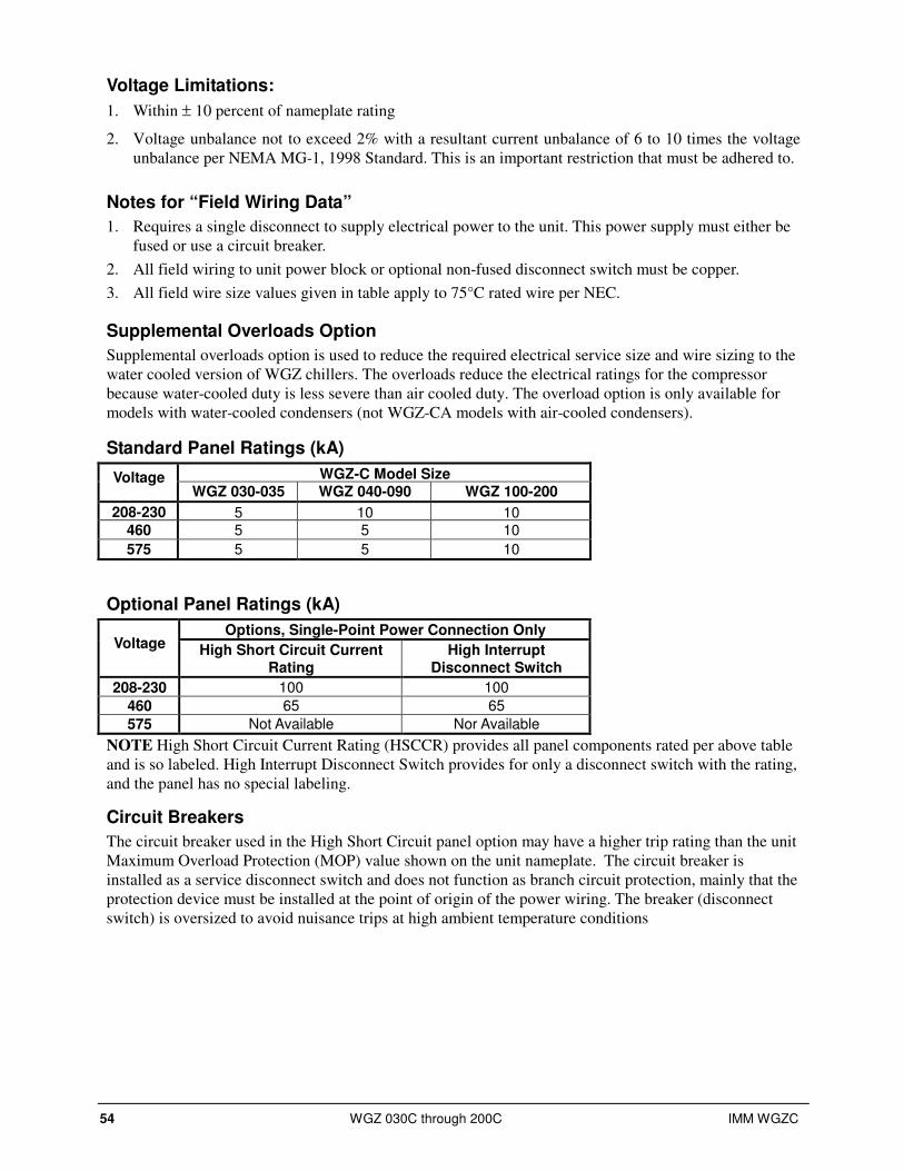
54 WGZ 030C through 200C IMM WGZC
Voltage Limitations:
1. Within ± 10 percent of nameplate rating
2. Voltage unbalance not to exceed 2% with a resultant current unbalance of 6 to 10 times the voltage
unbalance per NEMA MG-1, 1998 Standard. This is an important restriction that must be adhered to.
Notes for “Field Wiring Data”
1. Requires a single disconnect to supply electrical power to the unit. This power supply must either be
fused or use a circuit breaker.
2. All field wiring to unit power block or optional non-fused disconnect switch must be copper.
3. All field wire size values given in table apply to 75°C rated wire per NEC.
Supplemental Overloads Option
Supplemental overloads option is used to reduce the required electrical service size and wire sizing to the
water cooled version of WGZ chillers. The overloads reduce the electrical ratings for the compressor
because water-cooled duty is less severe than air cooled duty. The overload option is only available for
models with water-cooled condensers (not WGZ-CA models with air-cooled condensers).
Standard Panel Ratings (kA)
WGZ-C Model Size Voltage WGZ 030-035 WGZ 040-090 WGZ 100-200
208-230 5 10 10 460 5 5 10
575 5 5 10
Optional Panel Ratings (kA)
Options, Single-Point Power Connection Only Voltage High Short Circuit Current
Rating High Interrupt
Disconnect Switch
208-230 100 100
460 65 65
575 Not Available Nor Available
NOTE High Short Circuit Current Rating (HSCCR) provides all panel components rated per above table
and is so labeled. High Interrupt Disconnect Switch provides for only a disconnect switch with the rating,
and the panel has no special labeling.
Circuit Breakers
The circuit breaker used in the High Short Circuit panel option may have a higher trip rating than the unit
Maximum Overload Protection (MOP) value shown on the unit nameplate. The circuit breaker is
installed as a service disconnect switch and does not function as branch circuit protection, mainly that the
protection device must be installed at the point of origin of the power wiring. The breaker (disconnect
switch) is oversized to avoid nuisance trips at high ambient temperature conditions

IMM WGZC WGZ 030C through 200C 55
Field Wiring Diagram
Figure 22, WGZ 030CW – 200CW Field Wiring Diagram
FIELD WIRING FOR WGZ030-200C
DWG. 330538901 REV.0D
PACKAGE/ WITH CONDENSER WITH MICROTECH CONTROLLER
TO COMPRESSOR(S)
AND FAN MOTORS
DISCONNECT(BY OTHERS)
3 PHASE
POWER
120VAC
CONTROL POWER
GND LUGUNIT MAIN
TERMINAL BLOCK
FUSED CONTROL
CIRCUIT TRANSFORMER
OPTION
120 VAC
TB1
TB1-20
CHW PUMP RELAY (BY OTHERS)120 VAC 1.0 AMP MAX
DISCONNECT(BY OTHERS)
N
FIELD
SUPPLIED
OPTION 10AFUSE
(BY OTHERS)CONTROLCIRCUIT
FUSE
2
1
N
120 VAC
14
11
NOTE: ALL FIELD WIRING TO BE
INSTALLED AS NEC CLASS 1
WIRING SYSTEM WITH CONDUCTOR
RATED 600 VOLTS
SUPPLY
GND
ALARM BELL RELAY
FACTORY SUPPLIED ALARM
FIELD WIREDALARMBELL
OPTION 10
15
CONTROLLER
70
68
HOT GAS BYPASS #2 SOLENOID24 VAC 1.0 AMP MAX.
70
67
HOT GAS BYPASS #1 SOLENOID24 VAC 1.0 AMP MAX.
65
63
LIQUID LINE #2 SOLENOID24 VAC 1.5 AMP MAX.
LESS
EVAPORATOR
ONLY
24 VAC
N
24 VAC
N
24 VAC
N
TB2
ICE MODE SWITCH
(BY OTHERS)
51
52
42
60
40
53
43
55
49
50
ALARM BELLRELAY
ALARM BELL OPTION
BELL
1 2
COM NO
AUTO
TIMECLOCK OFF
ON
MANUAL
AUTO OFF
ON
MANUAL
REMOTE STOP
SWITCH
(BY OTHERS)
IF REMOTE STOP
CONTROL IS USED,REMOVE LEAD 897
FROM TERM. 40 TO 53.
897
4-20MA FOREVAP. WATER RESET
(BY OTHERS)
+
-
4-20MA FOR
DEMAND LIMIT(BY OTHERS)
+
GND
-
33
44
CHW FLOW SWITCH---MANDATORY–-
(BY OTHERS)
NOR. OPEN PUMP AUX. CONTACTS (OPTIONAL)
41
54
CDW FLOW SWITCH---MANDATORY–-
(BY OTHERS)
NOR. OPEN PUMP AUX. CONTACTS (OPTIONAL)
65
62
LIQUID LINE #1 SOLENOID24 VAC 1.5 AMP MAX.
N
24 VAC
N
N
120 VAC
120 VAC
120 VAC
120 VAC
CDW PUMP RELAY (BY OTHERS)120 VAC 1.0 AMP MAX
TOWER FAN #1 COIL (BY OTHERS)120 VAC 1.0 AMP MAX
TOWER FAN #2 COIL (BY OTHERS)120 VAC 1.0 AMP MAX
TB1-12
J15-NO8
TB1-12
J16-NO9
J16-NO10
TB3-90
TB3-91
TB3-92
79
80N
0-10 VDC77
78N
0-10 VDCCOOLING TOWER BYPASS
(BY OTHERS)
COOLING TOWER BYPASS
(BY OTHERS)
TB3
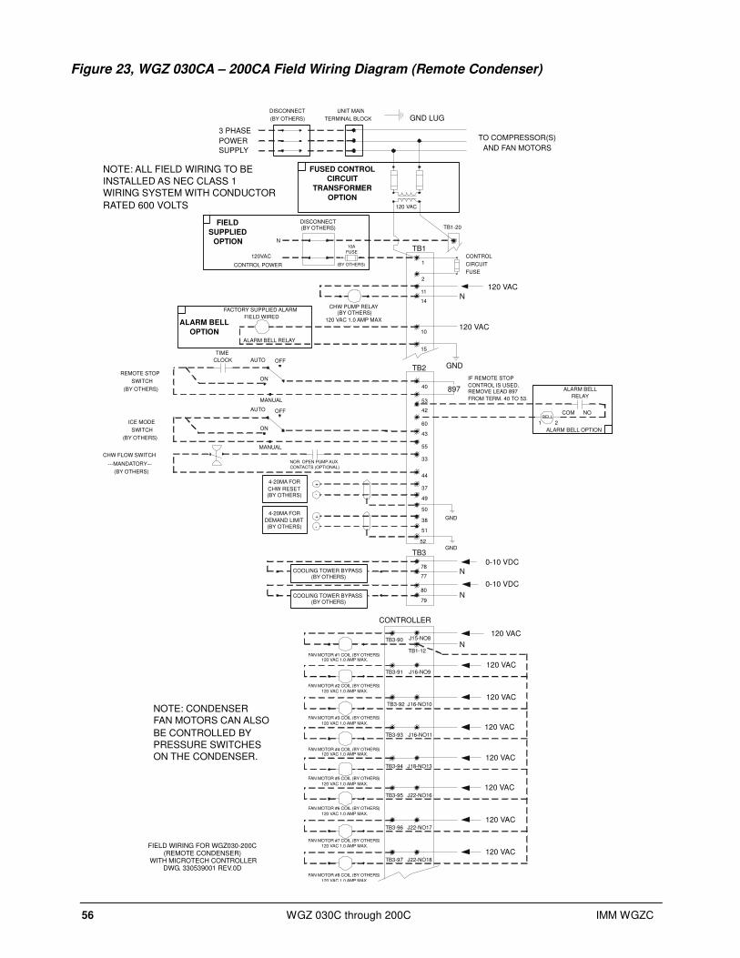
56 WGZ 030C through 200C IMM WGZC
Figure 23, WGZ 030CA – 200CA Field Wiring Diagram (Remote Condenser)
FIELD WIRING FOR WGZ030-200C(REMOTE CONDENSER)
WITH MICROTECH CONTROLLERDWG. 330539001 REV.0D
TB2
ICE MODE
SWITCH
(BY OTHERS)
TO COMPRESSOR(S)
AND FAN MOTORS
DISCONNECT
(BY OTHERS)
3 PHASE
POWER
120VAC
CONTROL POWER
UNIT MAIN
TERMINAL BLOCK
FUSED CONTROL
CIRCUIT
TRANSFORMER
OPTION120 VAC
TB1
TB1-20
CHW PUMP RELAY(BY OTHERS)
120 VAC 1.0 AMP MAX
DISCONNECT(BY OTHERS)
N
FIELD
SUPPLIED
OPTION10A
FUSE
(BY OTHERS)
CONTROL
CIRCUIT
FUSE
120 VAC
GND
ALARM BELL RELAY
FACTORY SUPPLIED ALARM
FIELD WIREDALARM BELL
OPTION
51
52
10
15
2
1
42
60
40
53
43
55
33
44
37
49
50
38
ALARM BELL
RELAY
ALARM BELL OPTION
BELL
1 2
COM NO
NOTE: ALL FIELD WIRING TO BE
INSTALLED AS NEC CLASS 1
WIRING SYSTEM WITH CONDUCTOR
RATED 600 VOLTS
SUPPLY
AUTO
TIME
CLOCK OFF
ON
MANUAL
AUTO OFF
ON
MANUAL
REMOTE STOP
SWITCH
(BY OTHERS)
IF REMOTE STOP
CONTROL IS USED,REMOVE LEAD 897
FROM TERM. 40 TO 53.
897
CHW FLOW SWITCH
---MANDATORY–-
(BY OTHERS)
NOR. OPEN PUMP AUX.
CONTACTS (OPTIONAL)
4-20MA FOR
CHW RESET(BY OTHERS)
+
GND
-
4-20MA FOR
DEMAND LIMIT(BY OTHERS)
+
GND
-
CONTROLLER
NOTE: CONDENSER
FAN MOTORS CAN ALSO
BE CONTROLLED BY
PRESSURE SWITCHES
ON THE CONDENSER.J18-NO13
J22-NO16
J22-NO17
J22-NO18
J16-NO9
J16-NO10
J16-NO11
120 VAC
120 VAC
120 VAC
120 VAC
120 VAC
120 VAC
120 VAC
FAN MOTOR #1 COIL (BY OTHERS)120 VAC 1.0 AMP MAX.
NTB1-12
J15-NO8120 VAC
FAN MOTOR #2 COIL (BY OTHERS)
120 VAC 1.0 AMP MAX.
FAN MOTOR #3 COIL (BY OTHERS)
120 VAC 1.0 AMP MAX.
FAN MOTOR #4 COIL (BY OTHERS)120 VAC 1.0 AMP MAX.
FAN MOTOR #5 COIL (BY OTHERS)
120 VAC 1.0 AMP MAX.
FAN MOTOR #6 COIL (BY OTHERS)
120 VAC 1.0 AMP MAX.
FAN MOTOR #7 COIL (BY OTHERS)
120 VAC 1.0 AMP MAX.
FAN MOTOR #8 COIL (BY OTHERS)
120 VAC 1.0 AMP MAX.
TB3-90
TB3-91
TB3-94
TB3-92
TB3-93
TB3-95
TB3-96
TB3-97
N
120 VAC
14
11
N
0-10 VDC
77
78
N79
80
TB3
COOLING TOWER BYPASS(BY OTHERS)
COOLING TOWER BYPASS(BY OTHERS)
0-10 VDC
GND LUG

IMM WGZC WGZ 030C through 200C 57
Control Panel Layout
Table 33, Typical Control Panel, 4-Compressor Unit w/ Optional Disconnect Switch
1. Additional space provided in the upper right section for extra components required for optional
multiple point power connection.
2. Front door has opening on top for access to the MicroTech II controller for viewing display and
making keypad entries without opening the panel door.
Motor Protection Module The motor protection system consists of an external control module, located on each compressor,
connected to a series of thermistors located in the motor windings and the compressor discharge port. If
the windings experience an over-temperature condition or the discharge temperature is excessive, the
module will trip and shut off the compressor for a 30-minute time delay.
(4) Compressor
Circuit Breakers
(3) 120V/24V
Transformers
LineV/120V
Control
Transformer
Control
Transformer
Fuses, Primary
Control
Transformer
Fuse, Secondary
Optional
Disconnect Switch
Microtech
Controller
(2) Circuit
Mechanical
Hi-Pressure
Switch Relays
(4) Compressor
Contactors
Grounding
Lug
Location for
Optional External
Overloads
7/8-in. KO for
control wiring
Switches
KO for Power
Wiring

58 WGZ 030C through 200C IMM WGZC
Start-Up and Shutdown
Complete operating instructions are contained in Operating Manual OM WGZC-Current.
Pre Start-up 1. The chilled-water system should be flushed and cleaned. Proper water treatment is required to
prevent corrosion and organic growth.
2. With main disconnect open, check all electrical connections in control panel and starter to be sure
they are tight and provide good electrical contact. Although connections are tightened at the factory,
they can loosen enough in shipment to cause a malfunction.
3. Check and inspect all water piping. Make sure flow direction is correct and piping is made to correct
connection on evaporator and condenser.
4. Open all water flow valves to the condenser and evaporator.
5. Flush the cooling tower and system piping to be sure the system is clean. Start evaporator pump and
manually start condenser pump and cooling tower. Check all piping for leaks. Vent the air from the
evaporator and condenser water circuit, as well as from the entire water system. The cooler circuit
should contain clean, treated, non-corrosive water.
6. Check to see that the evaporator water thermostat sensor is securely installed.
7. Making sure control stop switch S1 is open (off) and pumpdown switches PS1 and PS2 are on
“manual pumpdown,” place the main power and control disconnect switches to “on.” This will
energize the crankcase heaters. Wait a minimum of 12 hours before starting the unit.
8. Check compressor oil level. Prior to start-up, the oil level should cover at least one-third of the oil
sight glass located in the equalizing line between the compressors or on the compressor.
9. Check water pressure drop across evaporator and condenser, and see that water flow is correct
(beginning on page 17) per the design flow rates.
10. Check the actual line voltage to the unit to make sure it is the same as called for on the compressor
nameplate, within + 10%, and that phase voltage unbalance does not exceed 3%. Verify that adequate
power supply and capacity is available to handle load.
11. Make sure all wiring and fuses are of the proper size. Also make sure that all interlock wiring is
completed per McQuay diagrams.
12. Verify that all mechanical and electrical inspections by code authorities have been completed.
13. Make sure all auxiliary load and control equipment is operative and that an adequate cooling load is
available for initial start-up.
Start-up 1. Open the compressor discharge shutoff valves until backseated. Always replace valve seal caps.
2. Open the two manual liquid line shutoff valves.
3. Check to see that the unit circuit breakers are in the “off” position.
4. Check to see that the pumpdown switches, PS1 and PS2, are in the “manual pumpdown” position and
the control system switch S1 is in the “off” position.
5. Put the main power and control circuit disconnects to the “on” position.
6. Verify crankcase heaters have operated for at least 12 hours prior to start-up. Crankcase should be
warm to the touch.
7. Check that the MicroTech II controller is set to the desired chilled water temperature.
8. Start the system auxiliary equipment for the installation by turning on the time clock, ambient
thermostat and/or remote on/off switch and water pumps.
IMM WGZC WGZ 030C through 200C 59
9. Check resets of all equipment protection controls.
10. Switch on the unit circuit breakers.
11. Set pumpdown switches PS1 and PS2 to “auto” for restart and normal operation.
12. Start the system by setting the system switch S1 to on.
13. After running the unit for a short time, check the oil level in each compressor crankcase, rotation of
condenser fans (if any), and check for flashing in the refrigerant sight glass.
14. After system performance has stabilized, it is necessary that the “Compressorized Equipment
Warranty Form” (Form No. 206036A) be completed to establish commencement of the warranty
period. Be sure to list the pressure drop across both vessels. This form is shipped with the unit and
after completion should be returned to the McQuayService Department through your sales
representative.
Weekend or Temporary Shutdown Move pumpdown switches PS1 and PS2 to the “manual pumpdown” position. After the compressors have
pumped down, turn off the chilled water pump. Note: With the unit in this condition, it will not restart
until these switches are turned back on. The unit has one-time pumpdown. It is important that the
compressors pump down before the water flow to the unit is interrupted to avoid freeze-up in the
evaporator.
Leave S1 on and power to the unit so that the crankcase heaters will remain energized.
Start-up after Temporary Shutdown 1. Start the water pumps.
2. With the control system switch S1 in the “on” position, move the pumpdown switches PS1 and PS2
to the “auto pumpdown” position.
3. Observe the unit operation for a short time, noting unusual sounds or possible cycling of
compressors.
4. Check compressor crankcase heaters.
Extended Shutdown 1. Close the manual liquid line shutoff valves.
2. After the compressors have pumped down, turn off the water pumps.
3. Turn off all power to the unit.
4. Move the control service switch S1 to the “off” position.
5. Close the discharge shutoff valves on the compressor(s) and the liquid outlet valves at the condenser.
6. Tag all opened disconnect switches to warn against start-up before opening the compressor suction
and discharge valves.
7. Drain all water from the unit evaporator, condenser, and chilled water piping if the unit is to be shut
down during the winter and exposed to below freezing temperatures. Do not leave the vessels or
piping open to the atmosphere over the shutdown period.
60 WGZ 030C through 200C IMM WGZC
Start-up after Extended Shutdown 1. Inspect all equipment to see that it is in satisfactory operating condition.
2. Remove all debris that has collected on the surface of the condenser coils (remote condenser models)
or check the cooling tower, if present.
3. Open the compressor discharge valves until backseated. Always replace valve seal caps.
4. Open the manual liquid line shutoff valves.
5. Check circuit breakers. They must be in the “off” position.
6. Check to see that the pumpdown switches PS1 and PS2 are in the “manual shutdown” position and
the control system switch S1 is in the “off” position.
7. Put the main power and control circuit disconnects to the “on” position.
8. Allow the crankcase heaters to operate for at least 12 hours prior to start-up.
9. Start the chilled water pump and purge the water piping as well as the evaporator in the unit.
10. Start the system auxiliary equipment for the installation by turning on the time clock, ambient
thermostat and/or remote on/off switch.
11. Check that the MicroTech II controller is set to the desired chilled water temperature.
12. Check resets of all equipment protection controls.
13. Switch the unit circuit breakers to “on.”
14. Start the system by setting the system switch S1 to “on.”
CAUTION
Most relays and terminals in the control center are powered when S1 is closed and the control circuit disconnect is on. Therefore, do not close S1 until ready for start-up or
serious equipment damage can occur.
15. Set pumpdown switches PS1 and PS2 to the “auto pumpdown” position for restart and normal
operation.
16. After running the unit for a short time, check the oil level in the compressor oil sight glass or in the
compressor's equalizing lines for flashing indicating possible refrigerant in the oil (see Maintenance
section beginning on page 61).

IMM WGZC WGZ 030C through 200C 61
System Maintenance
General To provide smooth operation at peak capacity and to avoid damage to package components, a program of
periodic inspections should be set up and followed. The following items are intended as a guide to be
used during inspection and must be combined with sound refrigeration and electrical practices to provide
trouble-free performance.
The liquid line sight glass/moisture indicator on all circuits must be checked to be sure that the glass is
full and clear and that the moisture indicator indicates a dry condition. If the indicator shows that a wet
condition exists or if bubbles show in the glass, even with a full refrigerant charge, the filter-drier element
must be changed.
Water supplies in some areas can tend to foul the water-cooled condenser to the point where cleaning is
necessary. The fouled condenser will be indicated by an abnormally high condenser approach temperature
(saturated discharge temperature minus leaving condenser water temperature) and can result in nuisance
trip-outs. To clean the condenser, mechanical cleaning or a chemical descaling solution should be used
according to the manufacturer’s directions.
Systems with remote air-cooled condensers require periodic cleaning of the finned surface of the
condenser coil.
Cleaning can be accomplished by using a cold water spray, brushing, vacuuming, or high-pressure air. No
tools should be used that could damage the coil tubes or fins.
The compressor oil level must be checked periodically to be sure that the level is at the center of the oil
sightglass located in the compressor's equalizing line or on the compressor itself. Low oil level can cause
inadequate lubrication and if oil must be added, use oils referred to in the following “Compressor
Lubrication” section.
A pressure tap has been provided on the liquid line downstream of the filter-drier and solenoid valve but
before the expansion valve. An accurate subcooled liquid pressure and temperature can be taken here.
The pressure read here could also provide an indication of excessive pressure drop through the filter-drier
and solenoid valve due to a clogging filter-drier. Note: A normal pressure drop through the solenoid valve
is approximately 3 psig (20.7 kPa) at full load conditions.
! CAUTION
Warranty may be affected if wiring is not in accordance with specifications. A blown fuse or tripped protector indicates a short ground or overload. Before replacing fuse or restarting compressor, the trouble must be found and corrected. It is important to have a qualified control
panel electrician service this panel. Unqualified tampering with the controls can cause serious damage to equipment and void the warranty.
62 WGZ 030C through 200C IMM WGZC
! DANGER
The panel is always energized to ground even when the system switch is off. To de-energize the complete panel including crankcase heaters, pull the main unit disconnect.
Failure to do so can result in severe personal injury or death.
If motor or compressor damage is suspected, do not restart until qualified service personnel have checked
the unit.
Electrical Terminals ! WARNING
To avoid injury from electric shock hazard, turn off all power and perform lockout and tag-out of source before continuing with the following service. Note that the unit might be
powered from multiple sources.
All power electrical terminals should be re-tightened every six months, as they tend to loosen due to
normal heating and cooling of the wire.
Compressor Lubrication The oil level should be watched carefully upon initial start-up and regularly thereafter.
All tandem and triple compressors on WGZ units come equipped with oil equalization lines connecting
the crankcase of each set of compressors in each refrigerant circuit. This allows the oil to move from one
compressor crankcase to the other during normal operation, and balance between the two when the
compressors are off. The oil sight glass is located in the equalization line on one circuit of the WGZ 070
and both circuits of WGZ 080 through WGZ 100. All other models have the oil sight glass in the
compressor body. In either case, the oil level should be 1/4 to 1/3 of the glass.
The units are factory-charged with lubricant and one of the following lubricants must be used if lubricant
is to be added to the system:
••• Copeland Ultra 22 CC
••• Mobil EAL Arctic 22 CC
••• ICI EMKARATE RL RL 32CF
Since POEs are very hygroscopic, they will quickly absorb moisture if exposed to air. Pump the lubricant
into the unit through a closed transfer system. Avoid overcharging the unit.
Oil can be added to the Copeland compressor through the oil fill hole in the crankcase. Special equipment is
required to add oil and the work should be done by qualified refrigeration technicians with the proper training
and equipment.
Sightglass and Moisture Indicator The refrigerant sight glasses should be observed periodically. A monthly observation should be adequate. A
clear glass of liquid indicates that there is adequate refrigerant charge in the system to provide proper feed
through the expansion valve. The sight glass should be clear when:
• Ambient temperature is above 75°F (23°C)
• Both compressors on a circuit are running
• All fans on a circuit are running
Bubbling refrigerant in the sight glass may occur at other conditions and may indicate that the system is short
of refrigerant charge. Refrigerant gas flashing in the sight glass could also indicate an excessive pressure drop
in the line, possibly due to a clogged filter-drier or a restriction elsewhere in the system. An element inside the
sight glass indicates what moisture condition corresponds to a given element color. If the sight glass does not
indicate a dry condition after about 12 hours of operation, the unit should be pumped down and the filter-
driers changed.

IMM WGZC WGZ 030C through 200C 63
If the system is suspected of being short of refrigerant, a qualified service technician with EPA
certification should be contacted to thoroughly check out the unit and add refrigerant if
necessary.
Crankcase Heaters The compressors are equipped with crankcase heaters. The function of the heater is to keep the
temperature in the crankcase high enough to prevent refrigerant from migrating to the
crankcase and condensing in the oil during off-cycle. When a system is to be started up
initially, the power to the heaters should be turned on for at least 12 hours before the
compressors are started. The crankcase should be up to about 80°F (26.7°C) before the system
is started up, to minimize lubrication problems or liquid slugging of compressor on start-up.
If the crankcase is cool (below 80°F) (26.7°C) and the oil level in the sight glass is full to top,
allow more time for oil to warm before starting the compressor.
The crankcase heaters are on whenever power is supplied to the unit and the compressor is not
running.
Optional Controls
Phase/Voltage Monitor (Optional) The phase/voltage monitor is a device that provides protection against three-phase electrical
motor loss due to power failure conditions, phase loss, and phase reversal. Whenever any of
these conditions occur, an input relay is deactivated, disconnecting power to the thermostatic
control circuit. The compressor does a rapid shutdown pump down.
The input relay remains deactivated until power line conditions return to an acceptable level.
Trip and reset delays have been provided to prevent nuisance tripping due to rapid power
fluctuations.
When three-phase power has been applied, the input relay should close and the “run light”
should come on. If the relay does not close, perform the following tests.
1. Check the voltages between L1-L2, L1-L3, and L2-L3. These voltages should be
approximately equal and within +10% of the rated three-phase line-to-line voltage.
2. If these voltages are extremely low or widely unbalanced, check the power system to
determine the cause of the problem.
3. If the voltages are good, turn off the power and inter-change any two of the supply power
leads at the disconnect switch.
This may be necessary, as the phase/voltage monitor is sensitive to phase reversal. Turn on the
power. The relay should now close after the appropriate delay.
Factory settings are as follows:
Voltage Setting, set at nameplate voltage.
Trip Delay Time, 2 seconds
Restart Delay Time, 60 seconds
64 WGZ 030C through 200C IMM WGZC
Hot Gas Bypass (Optional) This option allows passage of discharge gas to the evaporator, permitting operation at lower
loads than available with compressor unloading. It also keeps the velocity of refrigerant gas
high enough for proper oil return at light load conditions.
The pressure regulating valve is a Sporlan® SHGBE-8 and factory set to begin opening at 69
psig and can be changed by changing the pressure setting. The adjustment range is 0 to 100
psig. To raise the pressure setting, remove the cap on the bulb and turn the adjustment screw
clockwise. To lower the setting, turn the screw counterclockwise. Do not force the adjustment
beyond the range it is designed for, as this will damage the adjustment assembly. The
regulating valve opening point can be determined by slowly reducing the system load while
observing the suction pressure. When the bypass valve starts to open, the refrigerant line on
the evaporator side of the valve will begin to feel warm to the touch.
! WARNING
The hot gas line can become hot enough to cause personal injury in a very short time; care should be taken during valve checkout

IMM WGZC WGZ 030C through 200C 65
Maintenance Schedule
I. Compressor
A. Performance Evaluation (Log & Analysis) * O
B. Motor
• Meg. Windings X
• Ampere Balance (within 10%) X
• Terminal Check (tight connections, porcelain clean) X
• Motor Cooling (check temperature) X
C. Lubrication System
• Oil Level O X
• Oil Appearance (clear color, quantity) O
• Oil change if indicated by oil analysis X
II. Controls
A. Operating Controls
• Check Settings and Operation X
B. Protective Controls
• Test Operation of:
Alarm Relay X
Pump Interlocks X
High and Low Pressure Cutouts X
III. Condenser
B. Test Water Quality X
C. Clean Condenser Tubes (or as required) X
D. Eddycurrent Test - Tube Wall Thickness X
E. Seasonal Protection X
IV. Evaporator
B. Test Water Quality X
C. Clean Evaporator Tubes (or as required) X
D. Eddycurrent Test - Tube Wall thickness (or as required) X
E. Seasonal Protection X
V. Expansion Valves
A. Performance Evaluation (Superheat Control) X
VI. Compressor - Chiller Unit
A. Performance Evaluation O
B. Leak Test:
• Compressor Fittings and Terminal X
• Piping Fittings X
• Vessel Relief Valves X
C. Vibration Isolation Test X
D. General Appearance:
• Paint X
• Insulation X
VII. Starter(s)
A. Examine Contactors (hardware and operation) X
B. Verify Overload Setting and Trip X
C. Test Electrical Connections X
VIII. Optional Controls
A. Hot Gas Bypass (verify operation) X
Key: O = Performed by in-house personnel X = Performed by service personnel

66 WGZ 030C through 200C IMM WGZC
System Service
! DANGER
Service on this equipment is to be performed only by qualified refrigeration personnel. Causes for repeated tripping of equipment protection controls must be investigated and corrected. Disconnect all power before doing any service inside the unit or serious personal injury or death can occur.
NOTE: Anyone servicing this equipment must comply with the requirements set forth by the EPA concerning refrigerant reclamation and venting.
Filter-Driers
To change the filter-drier, pump the unit down (with the compressor running) by closing the manual
liquid line shutoff valve(s). The unit will start pumping down until it reaches the low-pressure cutoff
setting of 58 psi.
Close the discharge valve. Remove the refrigerant in the liquid line with a recovery unit to EPA
required pressure. Remove and replace the filter-drier(s). Evacuate the lines through the liquid line
manual shutoff valve(s) to remove noncondensables that may have entered during filter replacement.
A leak check is recommended before returning the unit to operation.
Liquid Line Solenoid Valve
The liquid line solenoid valve(s), which are responsible for automatic pumpdown during normal unit
operation, do not normally require any maintenance. However, in the event of failure they can require
replacement of the solenoid coil or of the entire valve assembly.
The solenoid coil can be removed from the valve body without opening the refrigerant piping by
moving pumpdown switch(es) PS1 and PS2 to the “manual” position.
The coil can then be removed from the valve body by simply removing a nut or snap-ring located at
the top of the coil. The coil can then be slipped off its mounting stud for replacement. Be sure to
replace the coil on its mounting stud before returning pumpdown switch(es) PS1 and PS2 to the “auto
pumpdown” position.
To replace the entire solenoid valve, follow the steps for changing a filter-drier.
Thermostatic Expansion Valve The expansion valve is responsible for allowing the proper amount of refrigerant to enter the
evaporator regardless of cooling load. It does this by maintaining a constant superheat. (Superheat is
the difference between refrigerant temperature as it leaves the evaporator and the saturation
temperature corresponding to the evaporator pressure). All WGZ chillers are factory set for between
8°F and 12°F (4.4°C to 6.7°C) superheat at full load.
To increase the superheat setting of the valve, remove the cap at the bottom of the valve to expose the
adjustment screw. Turn the screw clockwise (when viewed from the adjustment screw end) to
increase the superheat and counterclockwise to reduce superheat. Allow time for system rebalance
after each superheat adjustment.
The expansion valve, like the solenoid valve, should not normally require replacement, but if it does,
the unit must be pumped down by following the steps involved when changing a filter-drier.
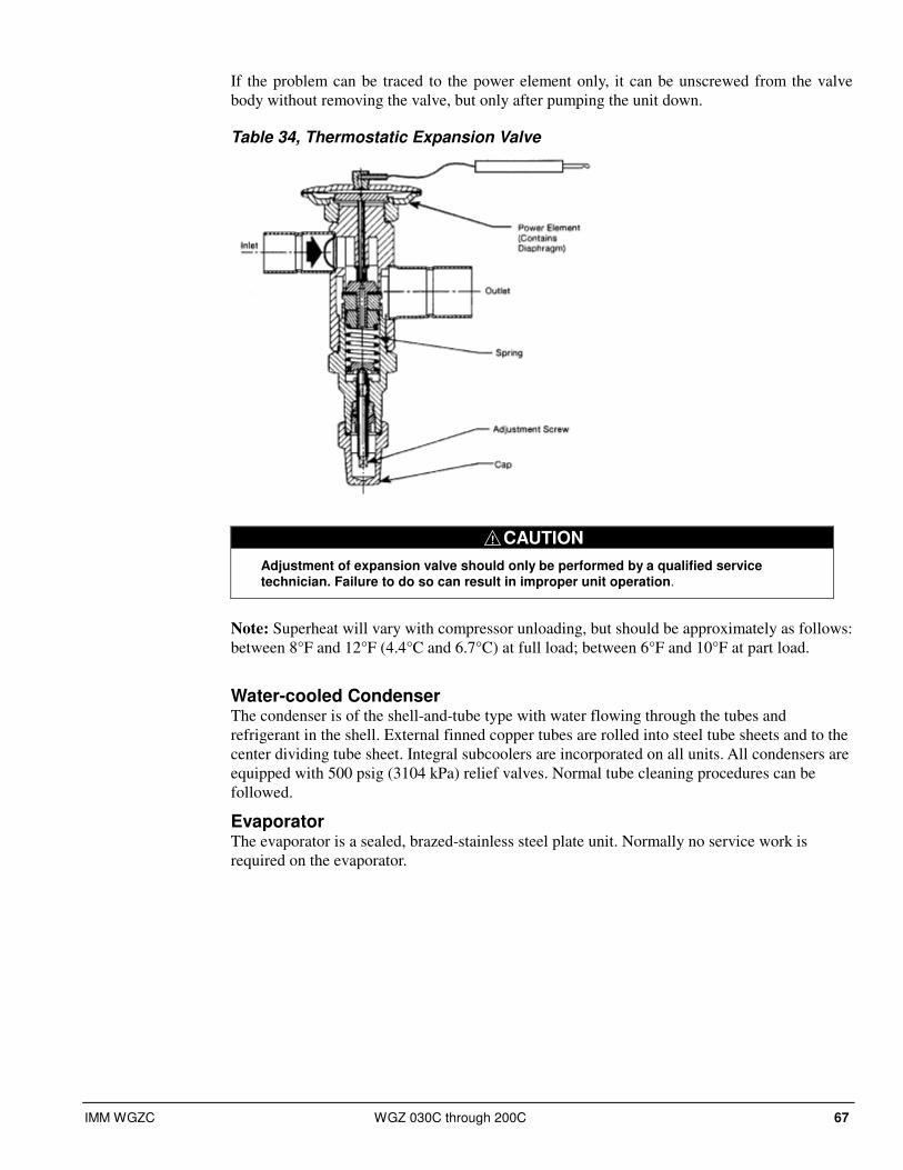
IMM WGZC WGZ 030C through 200C 67
If the problem can be traced to the power element only, it can be unscrewed from the valve
body without removing the valve, but only after pumping the unit down.
Table 34, Thermostatic Expansion Valve
! CAUTION
Adjustment of expansion valve should only be performed by a qualified service technician. Failure to do so can result in improper unit operation.
Note: Superheat will vary with compressor unloading, but should be approximately as follows:
between 8°F and 12°F (4.4°C and 6.7°C) at full load; between 6°F and 10°F at part load.
Water-cooled Condenser The condenser is of the shell-and-tube type with water flowing through the tubes and
refrigerant in the shell. External finned copper tubes are rolled into steel tube sheets and to the
center dividing tube sheet. Integral subcoolers are incorporated on all units. All condensers are
equipped with 500 psig (3104 kPa) relief valves. Normal tube cleaning procedures can be
followed.
Evaporator The evaporator is a sealed, brazed-stainless steel plate unit. Normally no service work is
required on the evaporator.
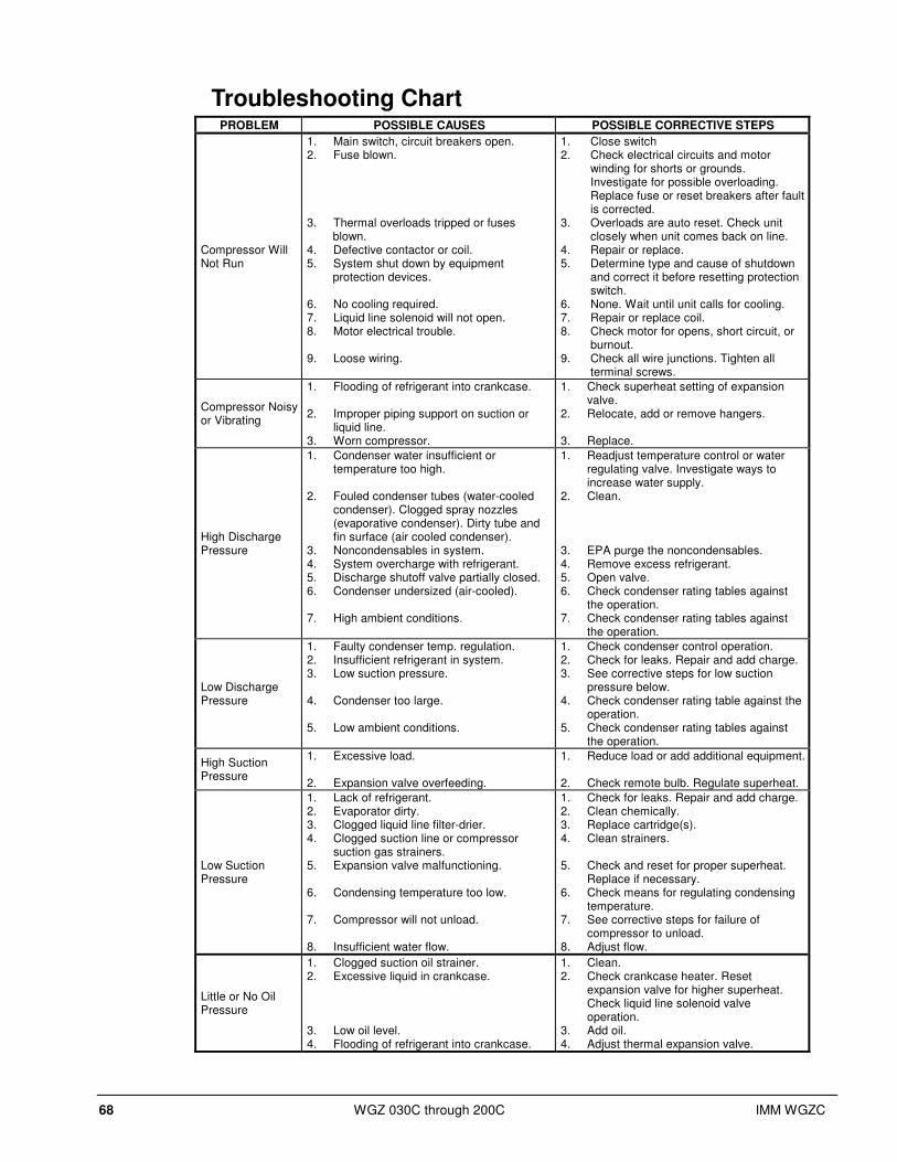
68 WGZ 030C through 200C IMM WGZC
Troubleshooting Chart PROBLEM POSSIBLE CAUSES POSSIBLE CORRECTIVE STEPS
Compressor Will Not Run
1. Main switch, circuit breakers open. 2. Fuse blown. 3. Thermal overloads tripped or fuses
blown. 4. Defective contactor or coil. 5. System shut down by equipment
protection devices. 6. No cooling required. 7. Liquid line solenoid will not open. 8. Motor electrical trouble. 9. Loose wiring.
1. Close switch 2. Check electrical circuits and motor
winding for shorts or grounds. Investigate for possible overloading. Replace fuse or reset breakers after fault is corrected.
3. Overloads are auto reset. Check unit closely when unit comes back on line.
4. Repair or replace. 5. Determine type and cause of shutdown
and correct it before resetting protection switch.
6. None. Wait until unit calls for cooling. 7. Repair or replace coil. 8. Check motor for opens, short circuit, or
burnout. 9. Check all wire junctions. Tighten all
terminal screws.
Compressor Noisy or Vibrating
1. Flooding of refrigerant into crankcase. 2. Improper piping support on suction or
liquid line. 3. Worn compressor.
1. Check superheat setting of expansion valve.
2. Relocate, add or remove hangers. 3. Replace.
High Discharge Pressure
1. Condenser water insufficient or temperature too high.
2. Fouled condenser tubes (water-cooled condenser). Clogged spray nozzles (evaporative condenser). Dirty tube and fin surface (air cooled condenser).
3. Noncondensables in system. 4. System overcharge with refrigerant. 5. Discharge shutoff valve partially closed. 6. Condenser undersized (air-cooled). 7. High ambient conditions.
1. Readjust temperature control or water regulating valve. Investigate ways to increase water supply.
2. Clean.
3. EPA purge the noncondensables. 4. Remove excess refrigerant. 5. Open valve. 6. Check condenser rating tables against
the operation. 7. Check condenser rating tables against
the operation.
Low Discharge Pressure
1. Faulty condenser temp. regulation. 2. Insufficient refrigerant in system. 3. Low suction pressure. 4. Condenser too large. 5. Low ambient conditions.
1. Check condenser control operation. 2. Check for leaks. Repair and add charge. 3. See corrective steps for low suction
pressure below. 4. Check condenser rating table against the
operation. 5. Check condenser rating tables against
the operation.
High Suction Pressure
1. Excessive load. 2. Expansion valve overfeeding.
1. Reduce load or add additional equipment.
2. Check remote bulb. Regulate superheat.
Low Suction Pressure
1. Lack of refrigerant. 2. Evaporator dirty. 3. Clogged liquid line filter-drier. 4. Clogged suction line or compressor
suction gas strainers. 5. Expansion valve malfunctioning. 6. Condensing temperature too low. 7. Compressor will not unload. 8. Insufficient water flow.
1. Check for leaks. Repair and add charge. 2. Clean chemically. 3. Replace cartridge(s). 4. Clean strainers. 5. Check and reset for proper superheat.
Replace if necessary. 6. Check means for regulating condensing
temperature. 7. See corrective steps for failure of
compressor to unload. 8. Adjust flow.
Little or No Oil Pressure
1. Clogged suction oil strainer. 2. Excessive liquid in crankcase. 3. Low oil level. 4. Flooding of refrigerant into crankcase.
1. Clean. 2. Check crankcase heater. Reset
expansion valve for higher superheat. Check liquid line solenoid valve operation.
3. Add oil. 4. Adjust thermal expansion valve.
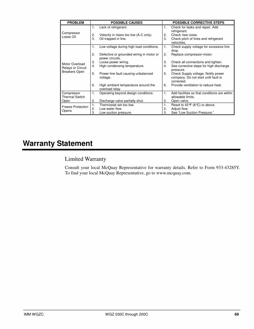
IMM WGZC WGZ 030C through 200C 69
PROBLEM POSSIBLE CAUSES POSSIBLE CORRECTIVE STEPS
Compressor Loses Oil
1. Lack of refrigerant. 2. Velocity in risers too low (A-C only). 3. Oil trapped in line.
1. Check for leaks and repair. Add refrigerant.
2. Check riser sizes. 3. Check pitch of lines and refrigerant
velocities.
Motor Overload Relays or Circuit Breakers Open
1. Low voltage during high load conditions. 2. Defective or grounded wiring in motor or
power circuits. 3. Loose power wiring. 4. High condensing temperature. 5. Power line fault causing unbalanced
voltage. 6. High ambient temperature around the
overload relay
1. Check supply voltage for excessive line drop.
2. Replace compressor-motor. 3. Check all connections and tighten. 4. See corrective steps for high discharge
pressure. 5. Check Supply voltage. Notify power
company. Do not start until fault is corrected.
6. Provide ventilation to reduce heat.
Compressor Thermal Switch Open
1. Operating beyond design conditions. 2. Discharge valve partially shut.
1. Add facilities so that conditions are within allowable limits.
2. Open valve.
Freeze Protection Opens
1. Thermostat set too low. 2. Low water flow. 3. Low suction pressure.
1. Reset to 42°F (6°C) or above. 2. Adjust flow. 3. See “Low Suction Pressure.”
Warranty Statement
Limited Warranty
Consult your local McQuay Representative for warranty details. Refer to Form 933-43285Y.
To find your local McQuay Representative, go to www.mcquay.com.

70 WGZ 030C through 200C IMM WGZC


(800) 432-1342 • www.mcquay.com IMM WGZC (4/11)
This document contains the most current product information as of this printing. For the most up-to-date product information, please go to www.mcquay.com. All McQuay equipment is sold pursuant to McQuay’s Standard Terms and Conditions of Sale and Limited Product Warranty. Consult your local McQuay Representative for warranty details. Refer to form 933-430285Y-00-A (09/08). To find your local representative, go to www.mcquay.com