Embed Size (px)
Citation preview

Global Industrial MANUAL NO. BL-GL33-0618 - 07-16-2019globalindustrial.com
MODEL 988993POWERED PALLET TRUCK
Operation
Maintenance
Repair Parts List
WARNING
Do not operate this truck unless you have been autho-rized and trained to do so, and have read all warningsand instructions in Operator’s Manual and on thistruck.
Do not operate this truck until you have checked itscondition. Give special attention to wheels, horn, bat-tery, controller, lift system, brakes, steering mecha-nism, guards and safety devices.
Operate truck only from designated operating position.Do not carry passengers. Keep feet clear of truck andwear foot protection.
Observe applicable traffic regulations. Yield right ofway to pedestrians. Slow down and sound horn atcross aisles and wherever vision is obstructed.
Start, stop, travel, steer and brake smoothly. Slowdown for turns and on uneven or slippery surfaces thatcould cause truck to slide or overturn. Use special
care when traveling without load as the risk of overturnmay be greater.
Always look in direction of travel. Keep a clear view,and when load interferes with visibility, travel with loadtrailing.
Use special care when operating on ramps travelslowly, and do not angle or turn. Travel with loaddownhill.
Do not handle loads which are higher than the chassisunless load is secured so that no part of it could fallbackward. Before lifting, be sure load is centered,forks are completely under the chassis backrest.
When leaving truck, neutralize travel control, fullylower lifting mechanism and set brake. When leavingtruck unattended, also shut off power.
BL-GL33-0618 - 07-16-2019
TABLE OF CONTENTS
Section Page Section Page
DESCRIPTION..................................................................1-11-1 INTRODUCTION. .........................................1-11-2 GENERAL DESCRIPTION ...........................1-11-3 SAFETY FEATURES....................................1-2
OPERATION.....................................................................2-12-1 GENERAL.....................................................2-12-2 OPERATING PRECAUTIONS......................2-12-3 BEFORE OPERATION.................................2-12-4 GENERAL CONTROL OPERATION............2-42-5 DRIVING AND STOPPING PROCEDURES 2-42-6 BELLY-BUTTON SWITCH............................2-42-7 STEERING ARM GAS SPRING ...................2-52-8 LIFT AND LOWER CONTROLS...................2-52-9 LOADING AND UNLOADING.......................2-52-10 PARKING......................................................2-5
PLANNED MAINTENANCE..............................................3-13-1 GENERAL.....................................................3-13-2 MONTHLY AND QUARTERLY CHECKS.....3-13-3 BATTERY CARE .........................................3-13-3.1 GENERAL.....................................................3-13-3.2 SAFETY RULES...........................................3-23-3.3 BATTERY CARE AND CHARGING .............3-23-3.4 BATTERY CLEANING 23-3.5 MAINTENANCE FREE BATTERIES ............3-23-4 CHARGING BATTERIES..............................3-33-5 BATTERY REPLACEMENT .........................3-43-6 LUBRICATION..............................................3-5
TROUBLESHOOTING......................................................4-14-1 GENERAL.....................................................4-14-2 CONTROLLER TROUBLESHOOTING ........4-44-2.1 FAULT DETECTION.....................................4-44-2.2 HAND HELD PROGRAMMER (OPTIONAL) 4-44-3.3 FAULT RECORDING....................................4-44-3.4 GENERAL CHECKOUT................................4-44-3.5 DIAGNOSTIC HISTORY...............................4-64-3.6 TEST THE FAULT DETECTION
CIRCUITRY ..................................................4-64-3.7 DIAGNOSTICS AND
TROUBLESHOOTING..................................4-64-3.7.1 LED Diagnostics ...........................................4-64-3.8 PROGRAMMER DIAGNOSTICS................4-16
STEERING ARM, CONTROL HEAD AND COMPARTMENT .....................................................5-1
5-1 CONTROL HEAD .........................................5-15-1.1 CONTROL HEAD REMOVAL.......................5-15-1.2 CONTROL HEAD INSTALLATION...............5-35-1.3 CONTROL HEAD COVERS REMOVAL.......5-35-1.4 CONTROL HEAD COVERS
INSTALLATION ............................................5-35-1.5 SPEED POTENTIOMETER
REPLACEMENT...........................................5-35-1.6 BELLY-BUTTON SWITCH REPLACEMENT5-4
5-1.7 HORN SWITCH REPLACEMENT................ 5-55-1.8 LIFT AND LOWER SWITCH
REPLACEMENT .......................................... 5-6
5-2 UPPER COMPARTMENT COVERS............ 5-75-2.1 REMOVAL.................................................... 5-75-2.2 INSTALLATION............................................ 5-75-3 LOWER COMPARTMENT COVERS........... 5-85-3.1 REMOVAL.................................................... 5-85-3.2 INSTALLATION............................................ 5-85-4 STEERING ARM.......................................... 5-95-4.1 RETURN SPRING REPLACEMENT............ 5-95-4.2 STEERING ARM REMOVAL ....................... 5-95-4.3 STEERING ARM INSTALLATION ............... 5-9
BRAKE SERVICING......................................................... 6-16-1 BRAKES....................................................... 6-16-1.1 BRAKE ASSEMBLY REPLACEMENT......... 6-1
TRANSMISSION, DRIVE WHEEL, LOAD WHEEL.......... 7-17-1 DRIVE WHEEL ............................................ 7-17-2 TRANSMISSION.......................................... 7-17-3 LOAD WHEEL.............................................. 7-37-3.1 REMOVAL.................................................... 7-37-3.2 REPAIR........................................................ 7-37-3.3 LOAD WHEEL INSTALLATION ................... 7-3
ELEVATION SYSTEM SERVICING................................. 8-18-1 LIFT LINKAGE ............................................. 8-18-1.1 REMOVAL.................................................... 8-18-1.2 REPAIR........................................................ 8-28-1.3 INSTALLATION............................................ 8-2
HYDRAULIC SYSTEM SERVICING ................................ 9-19-1 LINES AND FITTINGS................................. 9-19-2 HYDRAULIC AND ELECTRICAL
ASSEMBLY REMOVAL ............................... 9-29-2.1 REMOVAL.................................................... 9-29-2.2 INSTALLATION............................................ 9-29-3 HYDRAULIC PUMP, MOTOR
AND RESERVOIR ASSY............................. 9-29-3.1 REMOVAL.................................................... 9-29-3.2 DISASSEMBLY AND REASSEMBLY.......... 9-29-3.3 INSTALLATION............................................ 9-29-4 LIFT CYLINDER........................................... 9-59-4.1. REMOVAL.................................................... 9-59-4.2 REPAIR........................................................ 9-59-4.3 INSTALLATION............................................ 9-6
ELECTRICAL COMPONENTS....................................... 10-110-1 ELECTRICAL CONTROL PANEL.............. 10-110-1.1 MAINTENANCE ......................................... 10-110-1.2 CLEANING................................................. 10-110-1.3 CONTROLLER REMOVAL ........................ 10-110-1.4 CONTROLLER INSTALLATION ................ 10-1
BL-GL33-0618 - 07-16-2019 1
TABLE OF CONTENTS - CONTINUED
Section Page Section Page
10-1.5 CHARGER REMOVAL............................... 10-110-1.6 CHARGER INSTALLATION....................... 10-110-1.7 COOLING FAN REMOVAL ........................ 10-310-1.8 COOLING FAN INSTALLATION................ 10-310-1.9 BUZZER REMOVAL .................................. 10-310-1.10 BUZZER INSTALLATION .......................... 10-310-1.11 KEY SWITCH REMOVAL .......................... 10-310-1.12 KEY SWITCH INSTALLATION .................. 10-310-1.13 BATTERY INDICATOR REMOVAL ........... 10-310-1.14 BATTERY INDICATOR INSTALLATION ... 10-310-1.15 EMERGENCY DISCONNECT REMOVAL. 10-3
10-1.16 EMERGENCY DISCONNECT INSTALL ....10-410-1.17 LIFT LIMIT SWITCH REMOVAL ................10-610-1.18 LIFT LIMIT SWITCH INSTALLATION ........10-610-2 PUMP MOTOR...........................................10-710-3 DRIVE MOTOR ..........................................10-710-4 DEADMAN SWITCH...................................10-710-4.1 REPLACEMENT.........................................10-7
OPTIONAL EQUIPMENT ...............................................11-1
ILLUSTRATED PARTS BREAKDOWN ..........................12-1
1-2 BL-GL33-0618 - 07-16-2019

SECTION 1DESCRIPTION
1-1. INTRODUCTION.
This publication describes the 24 volt 988993 lift truckdistributed by Global Industrial. Included are operatinginstructions, planned maintenance instructions, lubri-cation procedures, corrective maintenance proceduresand a complete parts list with part location illustrations.
Users shall comply with all requirements indicated inapplicable OSHA standards and current edition ofA.N.S.I. B56.1 Part II. By following these requirementsand the recommendations contained in this manual,you will receive many years of dependable servicefrom your 988993 lift truck.
1-2. GENERAL DESCRIPTION.
The self-propelled 988993 truck, Figure 1-2, lifts andtransports payloads up to 3300 pounds on rigid forks.
The forward and reverse motion is controlled by eitherof two controller levers mounted on the control head.Stopping and turning is controlled by the steering arm.Lift and Lower is controlled by pushbuttons on the con-trol head. The battery powered lift truck is quiet andwithout exhaust fumes.
The reversible DC motor propels the lift truck in for-ward or reverse direction throughout the availablespeed range. The 988993 lift truck can be driven withforks raised or lowered. The lift truck must be pro-tected from the elements.
The model number will be found on the name plate(Figure 1-1) along with the serial number, lifting capac-ity, and load center. Figure 1-2 shows the locations ofthe truck’s main components and controls.
Figure 1-1 Name Plate
R8548
BL-GL33-0618 - 07-16-2019 1-1

Figure 1-2 Lift Truck
1-3. SAFETY FEATURES.
The 988993 is designed and engineered to providemaximum safety for operator and payload. Some ofthe safety features incorporated into the design are:
• Dead-man brake to apply the brake and cut off drivepower when the steering arm is released.
• Belly-button switch to reverse truck should the oper-ator accidentally pin himself against a wall orobstruction when backing up in slow speed.
• All control functions automatically return to “OFF”when released.
• Emergency Disconnect within operator's reach.
• Readily accessible horn button.
• Handle to provide a firm hand hold for operator.
• Flow control valve regulates maximum loweringspeed within prescribed limits.
• Relief valve maintains hydraulic pressure within pre-scribed limits.
• High visibility color scheme of truck provides visualalert of truck’s presence.
• Battery Indicator
GL33-14
1-2 BL-GL33-0618 - 07-16-2019

SECTION 2OPERATION
2-1. GENERAL.
This section gives detailed operating instructions forthe 988993 lift truck. The instructions are divided intothe various phases of operations, such as operatinglift, driving, and stopping. Routine precautions areincluded for safe operation.
2-2. OPERATING PRECAUTIONS.
WARNING: Improper operation of the lift truck mayresult in operator injury, or load and/or lifttruck damage. Observe the followingprecautions when operating the 988993lift truck.
The following safety precautions must be adhered toat all times.
• Do not operate this truck unless you have beentrained and authorized to do so and have read allwarnings and instructions in this manual and on thetruck.
• All warnings and instructions must be read andunderstood before using the equipment.
• Equipment must be inspected by a qualified personon a regular basis.
• Do not operate this truck until you have checked itscondition. Give special attention to Wheels, Horn,Batteries, Controller, Lift System, Brakes, SteeringMechanism, Guards and Safety Devices
• Operate truck only from designated operation posi-tion. Wear foot protection. Do not carry passengers.
• Observe applicable traffic regulations. Yield right ofway to pedestrians. Slow down and sound horn atcross aisles and wherever vision is obstructed.
• Start, stop, travel, steer and brake smoothly. Slowdown for turns and on uneven or slippery surfacesthat could cause truck to slide or overturn. Use spe-cial care when traveling without load as the risk ofoverturn may be greater.
• Always look in direction of travel. Keep a clear view,and when load interferes with visibility, travel withload or lifting mechanism trailing.
• Do not overload truck. Check nameplate for loadweight and load center information.
• Before lifting, be sure load is centered, forks arecompletely under load, and load is as far back aspossible against the chassis.
• Do not handle loads which are higher than the chas-sis unless load is secured so that no part of it couldfall backward.
• When leaving truck, neutralize travel control. Fullylower lifting mechanism and set brake. When leavingtruck unattended, turn off key switch and disconnectswitch, and remove key.
2-3. BEFORE OPERATION
Table 2-1 covers important inspection points on the988993 lift truck which should be checked prior tooperation. Depending on use, some trucks mayrequire additional checks.
Figure 2-1 shows a sample format for an OperatorChecklist, which can be modified as necessary to fityour operation.
WARNING: Periodic maintenance of this truck by aQUALIFIED TECHNICIAN is required.
CAUTION: A QUALIFIED SERVICE TECHNICIANshould check the truck monthly forproper lubrication, proper fluid levels,brake operation, motor maintenance andother areas specified in the SECTION 3.
WARNING: If the truck is found to be unsafe and inneed of repair, or contributes to anunsafe condition, report it immediately tothe designated authority. Do not operateit until it has been restored to a safeoperating condition. Do not make anyunauthorized repairs or adjustments. Allservice must be performed by a qualifiedmaintenance technician.
BL-GL33-0618 - 07-16-2019 2-1
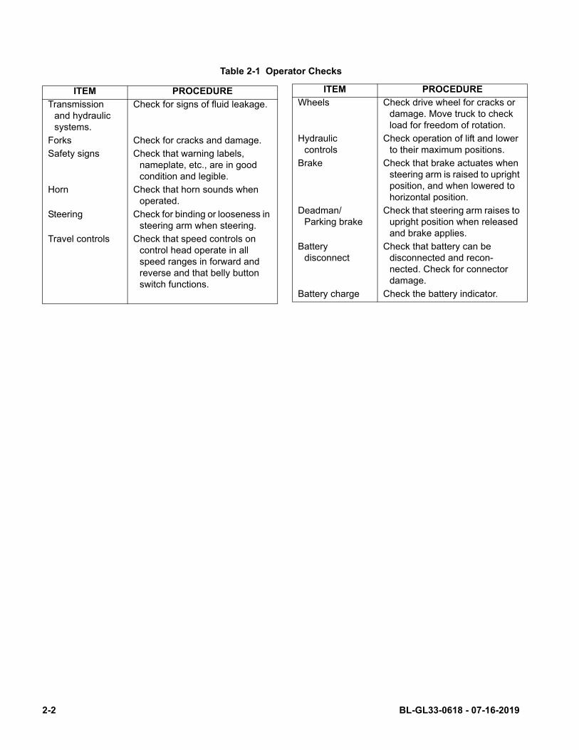
Table 2-1 Operator Checks
ITEM PROCEDURE
Transmission and hydraulic systems.
Check for signs of fluid leakage.
Forks Check for cracks and damage.
Safety signs Check that warning labels, nameplate, etc., are in good condition and legible.
Horn Check that horn sounds when operated.
Steering Check for binding or looseness in steering arm when steering.
Travel controls Check that speed controls on control head operate in all speed ranges in forward and reverse and that belly button switch functions.
Wheels Check drive wheel for cracks or damage. Move truck to check load for freedom of rotation.
Hydraulic controls
Check operation of lift and lower to their maximum positions.
Brake Check that brake actuates when steering arm is raised to upright position, and when lowered to horizontal position.
Deadman/Parking brake
Check that steering arm raises to upright position when released and brake applies.
Battery disconnect
Check that battery can be disconnected and recon-nected. Check for connector damage.
Battery charge Check the battery indicator.
ITEM PROCEDURE
2-2 BL-GL33-0618 - 07-16-2019
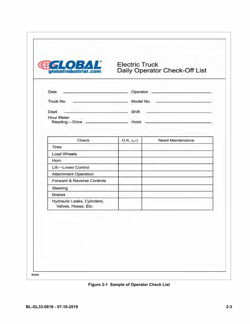
Figure 2-1 Sample of Operator Check List
R8549
BL-GL33-0618 - 07-16-2019 2-3
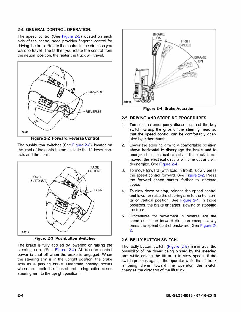
2-4. GENERAL CONTROL OPERATION.
The speed control (See Figure 2-2) located on eachside of the control head provides fingertip control fordriving the truck. Rotate the control in the direction youwant to travel. The farther you rotate the control fromthe neutral position, the faster the truck will travel.
Figure 2-2 Forward/Reverse Control
The pushbutton switches (See Figure 2-3), located onthe front of the control head activate the lift-lower con-trols and the horn.
Figure 2-3 Pushbutton Switches
The brake is fully applied by lowering or raising thesteering arm. (See Figure 2-4) All traction controlpower is shut off when the brake is engaged. Whenthe steering arm is in the upright position, the brakeacts as a parking brake. Deadman braking occurswhen the handle is released and spring action raisessteering arm to the upright position.
Figure 2-4 Brake Actuation
2-5. DRIVING AND STOPPING PROCEDURES.
1. Turn on the emergency disconnect and the keyswitch. Grasp the grips of the steering head sothat the speed control can be comfortably oper-ated by either thumb.
2. Lower the steering arm to a comfortable positionabove horizontal to disengage the brake and toenergize the electrical circuits. If the truck is notmoved, the electrical circuits will time out and willdeenergize. See Figure 2-4.
3. To move forward (with load in front), slowly pressthe speed control forward. See Figure 2-2. Pressthe forward speed control farther to increasespeed.
4. To slow down or stop, release the speed controland lower or raise the steering arm to the horizon-tal or vertical position. See Figure 2-4. In thosepositions, the brake engages, slowing or stoppingthe truck.
5. Procedures for movement in reverse are thesame as in the forward direction except slowlypress the speed control backward. See Figure 2-2.
2-6. BELLY-BUTTON SWITCH.
The belly-button switch (Figure 2-5) minimizes thepossibility of the driver being pinned by the steeringarm while driving the lift truck in slow speed. If theswitch presses against the operator while the lift truckis being driven toward the operator, the switchchanges the direction of the lift truck.
R6617
R6618
R8505
2-4 BL-GL33-0618 - 07-16-2019

Figure 2-5 Belly-Button Switch
2-7. STEERING ARM GAS SPRING.
The steering arm gas spring automatically raises thesteering arm to the upright position when the steeringarm is released. If the steering arm does not returnfully, the steering arm gas spring requires replace-ment. Return truck to maintenance for repair.
2-8. LIFT AND LOWER CONTROLS.
Lift/Lower Control buttons are located on the steeringcontrol head. (Figure 2-3)
To lift forks, push in either LIFT button and hold untilforks reach desired height. To lower forks, push ineither LOWER button and hold until forks descend todesired height.
2-9. LOADING AND UNLOADING.
1. Move truck to location where load is to be pickedup.
2. Move the truck into position so forks are withinpallet or skid, and the load is centered over theforks and as far back as possible.
3. Raise forks to lift load.
4. Drive to area where load is to be placed.
5. Move truck to align load with its new position.
6. Lower the load until it rests squarely in place andthe forks are free.
7. Slowly move the truck out from under the load.
2-10.PARKING.
When finished with moving loads, return the truck to itsmaintenance or storage area. Turn off the emergencyDisconnect and the key switch. Charge batteries asnecessary. Refer to battery care instructions, SEC-TION 3.
R6619
BL-GL33-0618 - 07-16-2019 2-5

NOTES
2-6 BL-GL33-0618 - 07-16-2019
SECTION 3PLANNED MAINTENANCE
3-1. GENERAL.
Planned maintenance consists of periodic visual andoperational checks, parts inspection, lubrication, andscheduled maintenance designed to prevent or dis-cover malfunctions and defective parts. The operatorperforms the checks in SECTION 3, and refers anyrequired servicing to a qualified maintenance techni-cian who performs the scheduled maintenance andany required servicing.
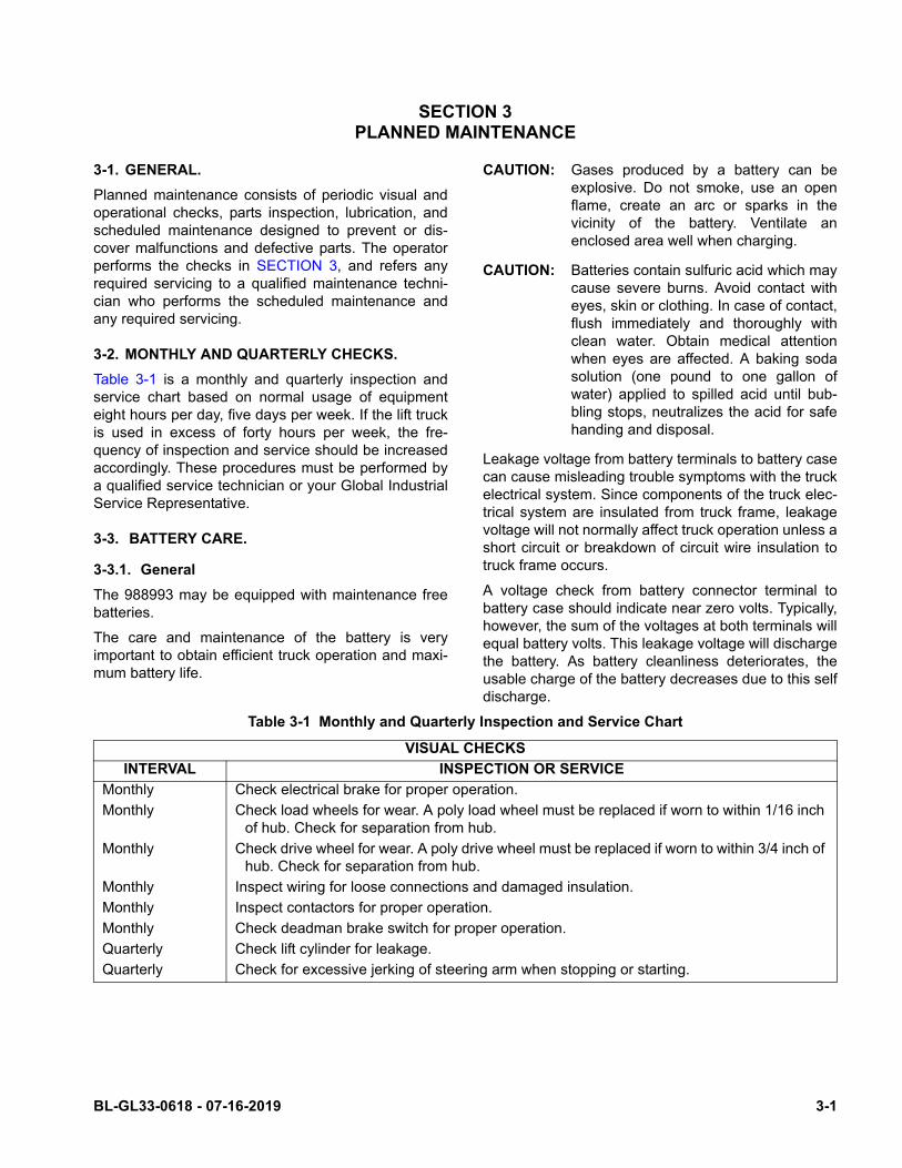
3-2. MONTHLY AND QUARTERLY CHECKS.
Table 3-1 is a monthly and quarterly inspection andservice chart based on normal usage of equipmenteight hours per day, five days per week. If the lift truckis used in excess of forty hours per week, the fre-quency of inspection and service should be increasedaccordingly. These procedures must be performed bya qualified service technician or your Global IndustrialService Representative.
3-3. BATTERY CARE.
3-3.1. General
The 988993 may be equipped with maintenance freebatteries.
The care and maintenance of the battery is veryimportant to obtain efficient truck operation and maxi-mum battery life.
CAUTION: Gases produced by a battery can beexplosive. Do not smoke, use an openflame, create an arc or sparks in thevicinity of the battery. Ventilate anenclosed area well when charging.
CAUTION: Batteries contain sulfuric acid which maycause severe burns. Avoid contact witheyes, skin or clothing. In case of contact,flush immediately and thoroughly withclean water. Obtain medical attentionwhen eyes are affected. A baking sodasolution (one pound to one gallon ofwater) applied to spilled acid until bub-bling stops, neutralizes the acid for safehanding and disposal.
Leakage voltage from battery terminals to battery casecan cause misleading trouble symptoms with the truckelectrical system. Since components of the truck elec-trical system are insulated from truck frame, leakagevoltage will not normally affect truck operation unless ashort circuit or breakdown of circuit wire insulation totruck frame occurs.
A voltage check from battery connector terminal tobattery case should indicate near zero volts. Typically,however, the sum of the voltages at both terminals willequal battery volts. This leakage voltage will dischargethe battery. As battery cleanliness deteriorates, theusable charge of the battery decreases due to this selfdischarge.
Table 3-1 Monthly and Quarterly Inspection and Service Chart
VISUAL CHECKS
INTERVAL INSPECTION OR SERVICE
Monthly Check electrical brake for proper operation.
Monthly Check load wheels for wear. A poly load wheel must be replaced if worn to within 1/16 inch of hub. Check for separation from hub.
Monthly Check drive wheel for wear. A poly drive wheel must be replaced if worn to within 3/4 inch of hub. Check for separation from hub.
Monthly Inspect wiring for loose connections and damaged insulation.
Monthly Inspect contactors for proper operation.
Monthly Check deadman brake switch for proper operation.
Quarterly Check lift cylinder for leakage.
Quarterly Check for excessive jerking of steering arm when stopping or starting.
BL-GL33-0618 - 07-16-2019 3-1
Although a leakage voltage reading of zero volts maynot be possible, a cleaner battery will have moreusable charge for truck operation and not affect opera-tion of electronic devices on the unit.
3-3.2. Safety Rules
• Wear protective clothing, such as rubber apron,gloves, boots and goggles when performing anymaintenance on batteries. Do not allow electrolyte tocome in contact with eyes, skin, clothing or floor. Ifelectrolyte comes in contact with eyes, flush immedi-ately and thoroughly with clean water. Obtain medi-cal attention immediately. Should electrolyte bespilled on skin, rinse promptly with clean water andwash with soap. A baking soda solution (one poundto one gallon of water) will neutralize acid spilled onclothing, floor or any other surface. Apply solutionuntil bubbing stops and rinse with clean water.
• If truck is equipped with wet cell batteries, keep ventplugs firmly in place at all times except when addingwater or taking hydrometer readings. Do not allowdirt, cleaning solution or other foreign material toenter cells. Impurities in electrolyte has a neutraliz-ing effect reducing available charge.
• Do not bring any type of flame, spark, etc., near thebattery. Gas formed while the battery is charging, ishighly explosive. This gas remains in cell long aftercharging has stopped.
• Do not lay metallic or conductive objects on battery.Arcing will result.
• Do not touch non-insulated parts of DC output con-nector or battery terminals to avoid possible electri-cal shock.
• De-energize all AC and DC power connectionsbefore servicing battery.
• Do not charge a frozen battery.
• Do not use charger if it has been dropped or other-wise damaged.
3-3.3. Battery Care and Charging
CAUTION: Never smoke or bring open flame nearthe battery. Gas formed during chargingis highly explosive and can cause seri-ous injury.
1. Charge the battery only in areas designated forthat use.
2. Battery terminals should be checked and cleanedof corrosion regularly. Good battery terminal con-tact is essential not only for operation, but also forproper charging of the battery.
3. The charging requirements will vary depending onthe use of the truck. The battery should be givenas equalizing charge on a weekly basis. Thischarge should normally be an additional threehours at the finish rate.
4. Make certain battery used meets weight and sizerequirements of truck. NEVER operate truck withan undersized battery.
3-3.4. Battery Cleaning
Always keep vent plugs tightly in place when cleaningbattery. When properly watered and charged, the bat-tery will remain clean and dry. All that is necessary isto brush or blow off any dust or dirt that may accumu-late on them. However, if electrolyte is spilled or over-flows from a cell, it should be neutralized with asolution of baking soda and water, brushing the sodasolution beneath the connectors and removing grimefrom the covers. Then rinse the battery with cool waterfrom a low pressure supply to remove the soda andloosen dirt. If batteries stay wet consistently, they maybe either overcharged or over filled. This conditionshould be investigated and corrected.
3-3.5. MAINTENANCE FREE BATTERIES
Some trucks may be equipped with maintenance freebatteries. These batteries are completely sealed, willnot require any watering and have a full 80% dis-charge available.
Sealed Maintenance Free batteries contain a pressurerelease valve and under normal operating conditionsdo not require any special ventilation.
CAUTION: Do not try to open this battery or removethe pressure release valve.
Only under severe overcharging, such as connectedto an improperly sized charger, will any significantamount of gasses be released from the battery. Also,being a valve regulated battery, it never requireswatering.
3-2 BL-GL33-0618 - 07-16-2019
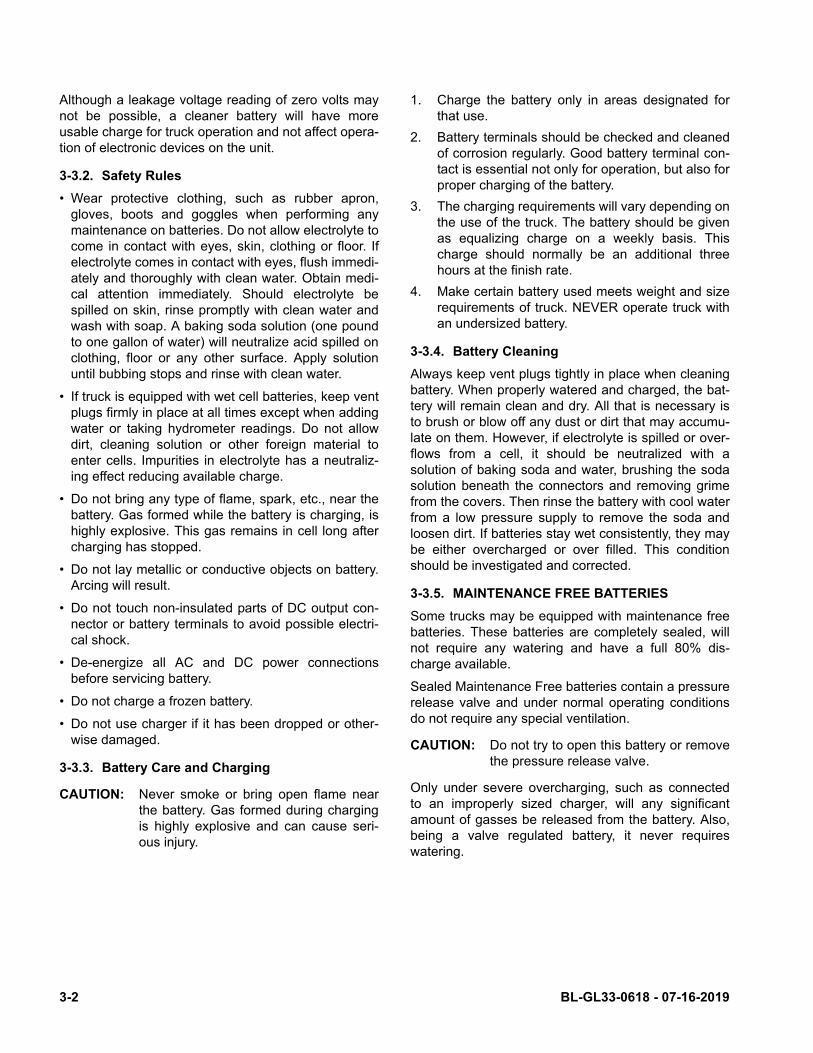
3-4. CHARGING BATTERIES
Charging requirements will vary depending on depth ofdischarge and temperature. Follow safety rules whenplacing a battery on charge.
Proceed as follows:
1. Park truck at charging station with forks loweredand turn the key switch off.
2. Check the condition of the AC cord and batterycables. If there are any cuts in the cable, anyexposed wires, loose plugs or connectors, DONOT attempt to charge the batteries. Contactappropriate personnel for repairs to be made.
3. Pull the charger cord out of the top cover (Figure3-1) and connect to the appropriate power supply.
Figure 3-1 Battery Charging
GL33-16
R6115
BL-GL33-0618 - 07-16-2019 3-3
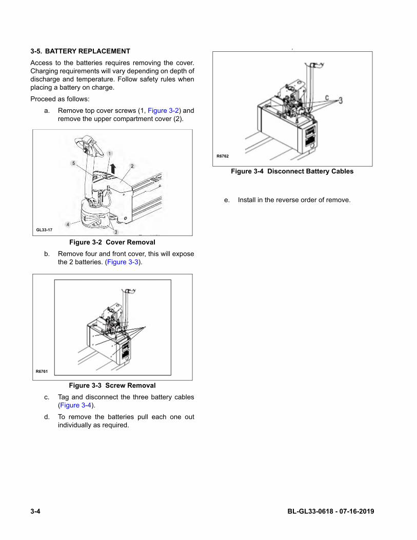
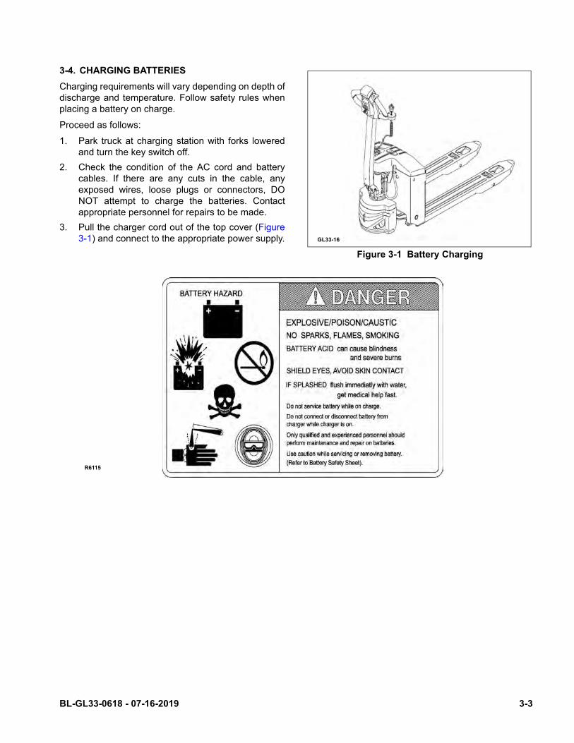
3-5. BATTERY REPLACEMENT
Access to the batteries requires removing the cover.Charging requirements will vary depending on depth ofdischarge and temperature. Follow safety rules whenplacing a battery on charge.
Proceed as follows:
a. Remove top cover screws (1, Figure 3-2) andremove the upper compartment cover (2).
Figure 3-2 Cover Removal
b. Remove four and front cover, this will exposethe 2 batteries. (Figure 3-3).
Figure 3-3 Screw Removal
c. Tag and disconnect the three battery cables(Figure 3-4).
d. To remove the batteries pull each one outindividually as required.
P
Figure 3-4 Disconnect Battery Cables
e. Install in the reverse order of remove.
GL33-17
R6761
R6762
3-4 BL-GL33-0618 - 07-16-2019
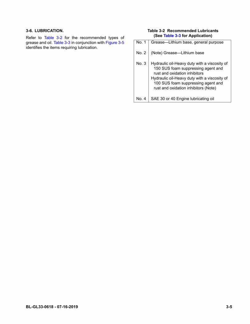
3-6. LUBRICATION.
Refer to Table 3-2 for the recommended types ofgrease and oil. Table 3-3 in conjunction with Figure 3-5identifies the items requiring lubrication.
Table 3-2 Recommended Lubricants(See Table 3-3 for Application)
No. 1 Grease—Lithium base, general purpose
No. 2 (Note) Grease—Lithium base
No. 3 Hydraulic oil-Heavy duty with a viscosity of 150 SUS foam suppressing agent and rust and oxidation inhibitors
Hydraulic oil-Heavy duty with a viscosity of 100 SUS foam suppressing agent and rust and oxidation inhibitors (Note)
No. 4 SAE 30 or 40 Engine lubricating oil
BL-GL33-0618 - 07-16-2019 3-5
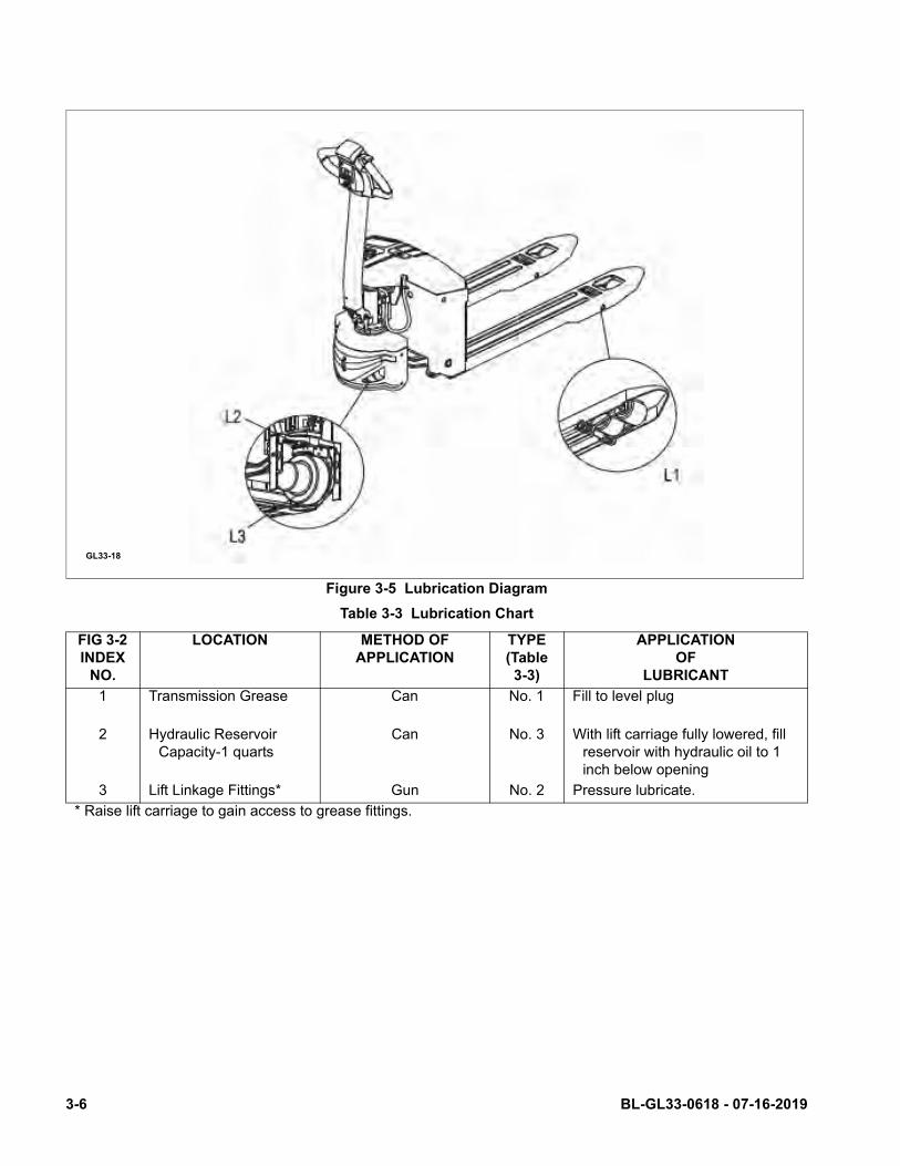
Figure 3-5 Lubrication Diagram
Table 3-3 Lubrication Chart
FIG 3-2 INDEX
NO.
LOCATION METHOD OF APPLICATION
TYPE (Table 3-3)
APPLICATION OF
LUBRICANT
1 Transmission Grease Can No. 1 Fill to level plug
2 Hydraulic ReservoirCapacity-1 quarts
Can No. 3 With lift carriage fully lowered, fill reservoir with hydraulic oil to 1 inch below opening
3 Lift Linkage Fittings* Gun No. 2 Pressure lubricate.
* Raise lift carriage to gain access to grease fittings.
GL33-18
3-6 BL-GL33-0618 - 07-16-2019
SECTION 4TROUBLESHOOTING
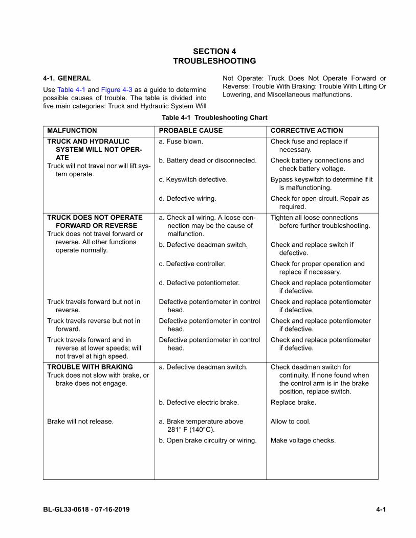
4-1. GENERAL
Use Table 4-1 and Figure 4-3 as a guide to determinepossible causes of trouble. The table is divided intofive main categories: Truck and Hydraulic System Will
Not Operate: Truck Does Not Operate Forward orReverse: Trouble With Braking: Trouble With Lifting OrLowering, and Miscellaneous malfunctions.
Table 4-1 Troubleshooting Chart
MALFUNCTION PROBABLE CAUSE CORRECTIVE ACTION
TRUCK AND HYDRAULIC SYSTEM WILL NOT OPER-ATE
Truck will not travel nor will lift sys-tem operate.
a. Fuse blown. Check fuse and replace if necessary.
b. Battery dead or disconnected. Check battery connections and check battery voltage.
c. Keyswitch defective. Bypass keyswitch to determine if it is malfunctioning.
d. Defective wiring. Check for open circuit. Repair as required.
TRUCK DOES NOT OPERATE FORWARD OR REVERSE
Truck does not travel forward or reverse. All other functions operate normally.
a. Check all wiring. A loose con-nection may be the cause of malfunction.
Tighten all loose connections before further troubleshooting.
b. Defective deadman switch. Check and replace switch if defective.
c. Defective controller. Check for proper operation and replace if necessary.
d. Defective potentiometer. Check and replace potentiometer if defective.
Truck travels forward but not in reverse.
Defective potentiometer in control head.
Check and replace potentiometer if defective.
Truck travels reverse but not in forward.
Defective potentiometer in control head.
Check and replace potentiometer if defective.
Truck travels forward and in reverse at lower speeds; will not travel at high speed.
Defective potentiometer in control head.
Check and replace potentiometer if defective.
TROUBLE WITH BRAKINGTruck does not slow with brake, or
brake does not engage.
a. Defective deadman switch. Check deadman switch for continuity. If none found when the control arm is in the brake position, replace switch.
b. Defective electric brake. Replace brake.
Brake will not release. a. Brake temperature above 281F (140C).
Allow to cool.
b. Open brake circuitry or wiring. Make voltage checks.
BL-GL33-0618 - 07-16-2019 4-1
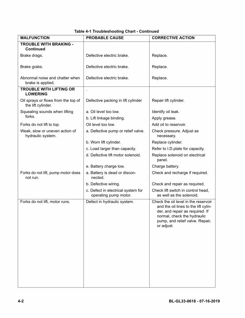
Table 4-1 Troubleshooting Chart - Continued
MALFUNCTION PROBABLE CAUSE CORRECTIVE ACTION
TROUBLE WITH BRAKING - Continued
Brake drags. Defective electric brake. Replace.
Brake grabs. Defective electric brake. Replace.
Abnormal noise and chatter when brake is applied.
Defective electric brake. Replace.
TROUBLE WITH LIFTING OR LOWERING
.
Oil sprays or flows from the top of the lift cylinder.
Defective packing in lift cylinder Repair lift cylinder.
Squealing sounds when lifting forks.
a. Oil level too low. Identify oil leak.
b. Lift linkage binding. Apply grease.
Forks do not lift to top. Oil level too low. Add oil to reservoir.
Weak, slow or uneven action of hydraulic system.
a. Defective pump or relief valve. Check pressure. Adjust as necessary.
b. Worn lift cylinder. Replace cylinder.
c. Load larger than capacity. Refer to I.D.plate for capacity.
d. Defective lift motor solenoid. Replace solenoid on electrical panel.
e. Battery charge low. Charge battery.
Forks do not lift, pump motor does not run.
a. Battery is dead or discon-nected.
Check and recharge if required.
b. Defective wiring. Check and repair as required.
c. Defect in electrical system for operating pump motor.
Check lift switch in control head, as well as the solenoid.
Forks do not lift, motor runs. Defect in hydraulic system. Check the oil level in the reservoir and the oil lines to the lift cylin-der, and repair as required. If normal, check the hydraulic pump, and relief valve. Repair, or adjust.
4-2 BL-GL33-0618 - 07-16-2019
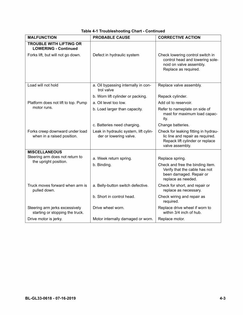
Table 4-1 Troubleshooting Chart - Continued
MALFUNCTION PROBABLE CAUSE CORRECTIVE ACTION
TROUBLE WITH LIFTING OR LOWERING - Continued
Forks lift, but will not go down. Defect in hydraulic system Check lowering control switch in control head and lowering sole-noid on valve assembly. Replace as required.
Load will not hold a. Oil bypassing internally in con-trol valve
Replace valve assembly.
b. Worn lift cylinder or packing. Repack cylinder.
Platform does not lift to top. Pump motor runs.
a. Oil level too low. Add oil to reservoir.
b. Load larger than capacity. Refer to nameplate on side of mast for maximum load capac-ity.
c. Batteries need charging. Change batteries.
Forks creep downward under load when in a raised position.
Leak in hydraulic system, lift cylin-der or lowering valve.
Check for leaking fitting in hydrau-lic line and repair as required. Repack lift cylinder or replace valve assembly.
MISCELLANEOUSSteering arm does not return to
the upright position.a. Week return spring. Replace spring.
b. Binding. Check and free the binding item. Verify that the cable has not been damaged. Repair or replace as needed.
Truck moves forward when arm is pulled down.
a. Belly-button switch defective. Check for short, and repair or replace as necessary.
b. Short in control head. Check wiring and repair as required.
Steering arm jerks excessively starting or stopping the truck.
Drive wheel worn. Replace drive wheel if worn to within 3/4 inch of hub.
Drive motor is jerky. Motor internally damaged or worn. Replace motor.
BL-GL33-0618 - 07-16-2019 4-3
4-2. CONTROLLER TROUBLESHOOTING
4-2.1. Fault Detection.
The controller provides diagnostics information toassist technicians in troubleshooting drive systemproblems. When a fault is detected, the appropriatefault code is signaled via the panel mounted LED.
4-2.2. Hand Held Programmer (Optional)
The hand held programmer is available that isdesigned specifically for use with the controller. Theprogrammer is available through your Global Industrialdealer.
4-2.3. Fault Recording.
Fault events are recorded in the controller's memory.However, multiple occurrences of the same fault arerecorded as one occurrence.
The fault event list can be loaded into the programmerfor readout. The Special Diagnostics mode providesaccess to the controller's diagnostic history file. Thehistory file contains the entire fault event list createdsince the diagnostic history file was last cleared. Thestandard Diagnostics mode provides information aboutonly the currently active faults.
4-2.4. General Checkout.
Carefully complete the following checkout procedure.If you find a problem during the checkout, refer toparagraph 4-2.7. for further information.
The checkout can be conducted with or without thehandheld programmer (See Paragraph 4-2.2.). How-ever, the checkout procedure is easier with a program-mer. To evaluate the system without a programmer,observe the LED and note the flashing pattern andrefer to for the code description.
CAUTION: Put the vehicle up on blocks to get thedrive wheel off the ground before begin-ning these tests.
Turn the keyswitch off and make sure thebrake is applied, the throttle is in neutral,and the forward/reverse switches areopen.
Do not stand, or allow anyone else tostand directly in front of or behind thevehicle during the tests.
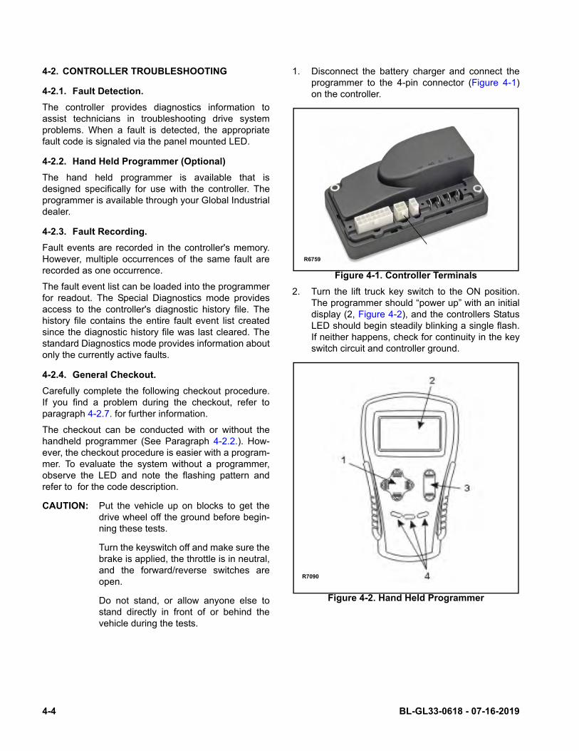
1. Disconnect the battery charger and connect theprogrammer to the 4-pin connector (Figure 4-1)on the controller.
Figure 4-1. Controller Terminals
2. Turn the lift truck key switch to the ON position.The programmer should “power up” with an initialdisplay (2, Figure 4-2), and the controllers StatusLED should begin steadily blinking a single flash.If neither happens, check for continuity in the keyswitch circuit and controller ground.
Figure 4-2. Hand Held Programmer
R6759
R7090
4-4 BL-GL33-0618 - 07-16-2019
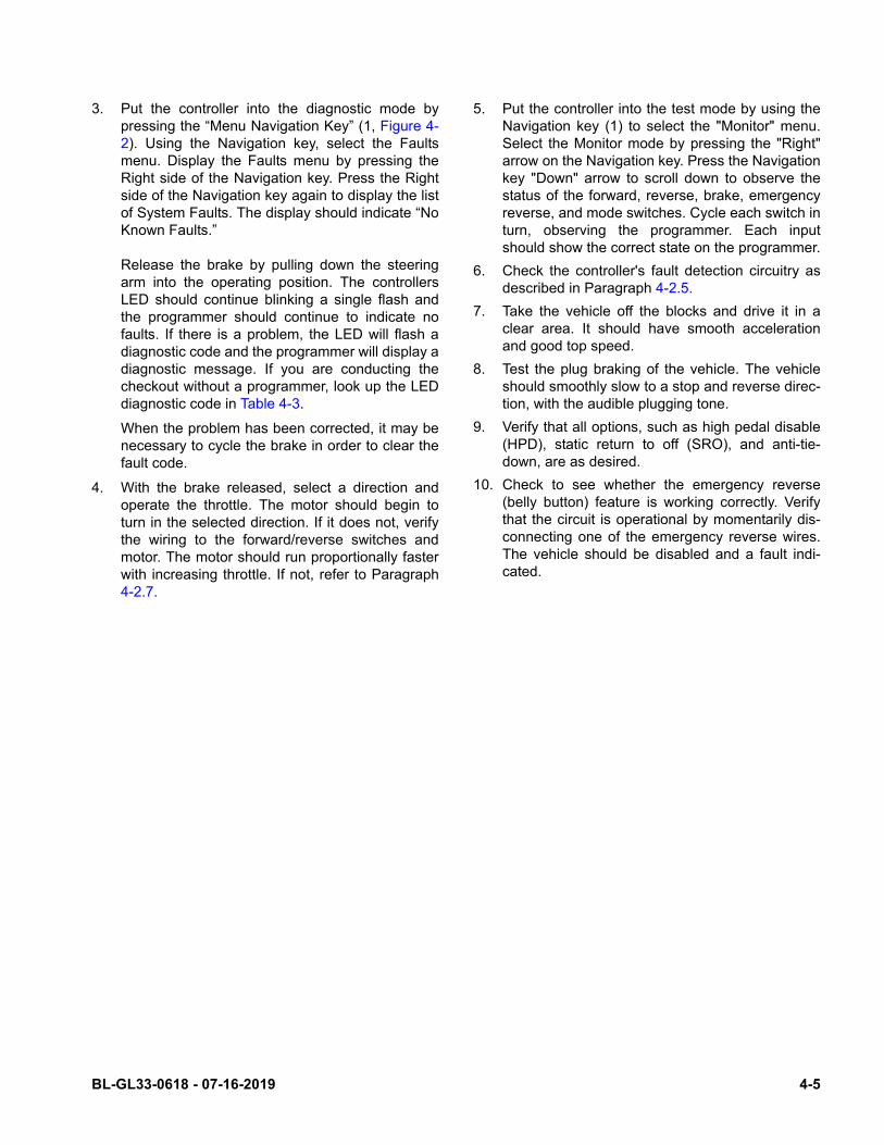
3. Put the controller into the diagnostic mode bypressing the “Menu Navigation Key” (1, Figure 4-2). Using the Navigation key, select the Faultsmenu. Display the Faults menu by pressing theRight side of the Navigation key. Press the Rightside of the Navigation key again to display the listof System Faults. The display should indicate “NoKnown Faults.”
Release the brake by pulling down the steeringarm into the operating position. The controllersLED should continue blinking a single flash andthe programmer should continue to indicate nofaults. If there is a problem, the LED will flash adiagnostic code and the programmer will display adiagnostic message. If you are conducting thecheckout without a programmer, look up the LEDdiagnostic code in Table 4-3.
When the problem has been corrected, it may benecessary to cycle the brake in order to clear thefault code.
4. With the brake released, select a direction andoperate the throttle. The motor should begin toturn in the selected direction. If it does not, verifythe wiring to the forward/reverse switches andmotor. The motor should run proportionally fasterwith increasing throttle. If not, refer to Paragraph4-2.7.
5. Put the controller into the test mode by using theNavigation key (1) to select the "Monitor" menu.Select the Monitor mode by pressing the "Right"arrow on the Navigation key. Press the Navigationkey "Down" arrow to scroll down to observe thestatus of the forward, reverse, brake, emergencyreverse, and mode switches. Cycle each switch inturn, observing the programmer. Each inputshould show the correct state on the programmer.
6. Check the controller's fault detection circuitry asdescribed in Paragraph 4-2.5.
7. Take the vehicle off the blocks and drive it in aclear area. It should have smooth accelerationand good top speed.
8. Test the plug braking of the vehicle. The vehicleshould smoothly slow to a stop and reverse direc-tion, with the audible plugging tone.
9. Verify that all options, such as high pedal disable(HPD), static return to off (SRO), and anti-tie-down, are as desired.
10. Check to see whether the emergency reverse(belly button) feature is working correctly. Verifythat the circuit is operational by momentarily dis-connecting one of the emergency reverse wires.The vehicle should be disabled and a fault indi-cated.
BL-GL33-0618 - 07-16-2019 4-5
4-2.5. Diagnostic History
The handheld programmer can be used to access thecontroller's diagnostic history file. When the program-mer is connected to the unit, the error log file is auto-matically uploaded into the handheld programmer.
To see the present status of the unit, use the MenuNavigation Key (1, Figure 4-2) to select:
Faults->System Faults.
To access this log, use the Menu Navigation Key toselect:
Faults->Fault History
The faults are shown as a code and descriptive text. Ifthere are multiple faults, you have to scroll through thelist using the Up and Down Buttons on the Menu Navi-gation Key
The faults may be intermittent faults, faults caused byloose wires, or faults caused by operator errors. Faultssuch as HPD or over-temperature may be caused byoperator habits or by overloading.
After a problem has been diagnosed and corrected,clearing the diagnostic history file is recommended.This allows the controller to accumulate a new file offaults. By checking the new diagnostic history file at alater date, you can quickly determine whether theproblem has been completely fixed.
To clear the diagnostic history file, select:
Faults->Clear Fault History.
You will be asked to confirm your actions. Use the"plus" arrow (+) for yes to clear the menu and the"minus" arrow (-) (3) to cancel your selection and notclear the Fault History.
4-2.6. Test the Fault Detection Circuitry
1. Put the vehicle up on blocks to get the drive wheeloff the ground.
1. Turn off the key switch and emergency discon-nect.
2. Using an inline fuse holder fitted with a 10 ampfuse and alligator clips, connect the controller's Mand B- terminals.
3. Turn on the emergency disconnect (17) the keyswitch (20). Release the brake and apply thethrottle. The motor should not operate.
4. Leave the key switch on and remove the in-linefuse wire. The vehicle status should continue toremain off.
5. Cycle the key switch off and on. Release thebrake and apply the throttle. The vehicle shouldnow operate normally.
4-2.7. Diagnostics and Troubleshooting.
The motor controller provides diagnostics informationto assist in troubleshooting drive system problems.The diagnostics information can be obtained in twoways:
• Reading the appropriate display on the programmer
• Observing the fault codes issued by the panelmounted Status LED.
4-2.7.1. LED Diagnostics
During normal operation with no faults present, theStatus LED is steady on. If the controller detects a faultthe Status LED flashes a fault identification code con-tinuously until the fault is corrected.
NOTE: The Status LED can only indicate one fault ata time. If multiple faults are detected, thehighest priority fault code flashes until it iscleared.
With Fault Code Type parameter is set to 0, the statusLED uses the fault codes listed in . Six single-digitcodes are used: 2, 3, 5, 6, 7, and 9.
For suggestions about possible causes of the variousfaults, refer to Table 4-3 Troubleshooting Chart.
4-6 BL-GL33-0618 - 07-16-2019
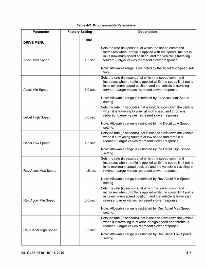
Table 4-2 Programmable Parameters
Parameter Factory Setting Description
90ADRIVE MENU
Accel Max Speed 1.5 sec.
Sets the rate (in seconds) at which the speed command increases when throttle is applied with the speed limit pot is in its maximum speed position, and the vehicle is traveling forward. Larger values represent slower response.
Note: Allowable range is restricted by the Accel Min Speed set-ting.
Accel Min Speed 5.0 sec.
Sets the rate (in seconds) at which the speed command increases when throttle is applied while the speed limit pot is in its minimum speed position, and the vehicle is traveling forward. Larger values represent slower response
Note: Allowable range is restricted by the Accel Max Speed setting.
Decel High Speed 0.6 sec.
Sets the rate (in seconds) that is used to slow down the vehicle when it is traveling forward at high speed and throttle is reduced. Larger values represent slower response.
Note: Allowable range is restricted by the Decel Low Speed setting.
Decel Low Speed 1.5 sec.
Sets the rate (in seconds) that is used to slow down the vehicle when it s traveling forward at low speed and throttle is reduced. Larger values represent slower response.
Note: Allowable range is restricted by the Decel High Speed setting.
Rev Accel Max Speed 1.5sec.
Sets the rate (in seconds) at which the speed command increases when throttle is applied while the speed limit pot is in its maximum speed position, and the vehicle is traveling in reverse. Larger values represent slower response.
Note: Allowable range is restricted by Rev Accel Min Speed setting.
Rev Accel Min Speed 5.0 sec.
Sets the rate (in seconds) at which the speed command increases when throttle is applied while the speed limit pot is in its minimum speed position, and the vehicle is traveling in reverse. Larger values represent slower response.
Note: Allowable range is restricted by Rev Accel Max Speed setting.
Rev Decel High Speed 0.5 sec.
Sets the rate (in seconds) that is used to slow down the vehicle when it is traveling in reverse at high speed and throttle is reduced. Larger values represent slower response.
Note: Allowable range is restricted by Rev Decel Low Speed setting.
BL-GL33-0618 - 07-16-2019 4-7
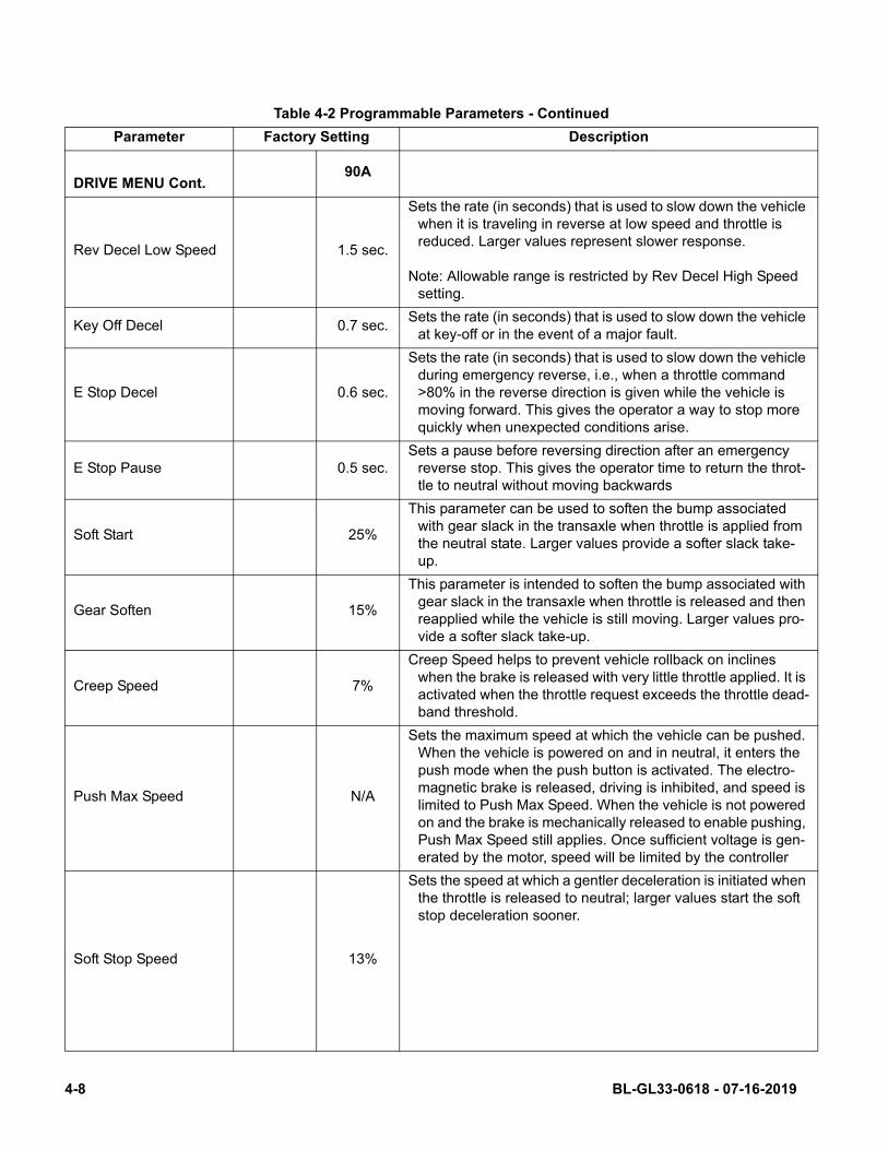
Table 4-2 Programmable Parameters - Continued
Parameter Factory Setting Description
90ADRIVE MENU Cont.
Rev Decel Low Speed 1.5 sec.
Sets the rate (in seconds) that is used to slow down the vehicle when it is traveling in reverse at low speed and throttle is reduced. Larger values represent slower response.
Note: Allowable range is restricted by Rev Decel High Speed setting.
Key Off Decel 0.7 sec.Sets the rate (in seconds) that is used to slow down the vehicle
at key-off or in the event of a major fault.
E Stop Decel 0.6 sec.
Sets the rate (in seconds) that is used to slow down the vehicle during emergency reverse, i.e., when a throttle command >80% in the reverse direction is given while the vehicle is moving forward. This gives the operator a way to stop more quickly when unexpected conditions arise.
E Stop Pause 0.5 sec.Sets a pause before reversing direction after an emergency
reverse stop. This gives the operator time to return the throt-tle to neutral without moving backwards
Soft Start 25%
This parameter can be used to soften the bump associated with gear slack in the transaxle when throttle is applied from the neutral state. Larger values provide a softer slack take-up.
Gear Soften 15%
This parameter is intended to soften the bump associated with gear slack in the transaxle when throttle is released and then reapplied while the vehicle is still moving. Larger values pro-vide a softer slack take-up.
Creep Speed 7%
Creep Speed helps to prevent vehicle rollback on inclines when the brake is released with very little throttle applied. It is activated when the throttle request exceeds the throttle dead-band threshold.
Push Max Speed N/A
Sets the maximum speed at which the vehicle can be pushed. When the vehicle is powered on and in neutral, it enters the push mode when the push button is activated. The electro-magnetic brake is released, driving is inhibited, and speed is limited to Push Max Speed. When the vehicle is not powered on and the brake is mechanically released to enable pushing, Push Max Speed still applies. Once sufficient voltage is gen-erated by the motor, speed will be limited by the controller
Soft Stop Speed 13%
Sets the speed at which a gentler deceleration is initiated when the throttle is released to neutral; larger values start the soft stop deceleration sooner.
4-8 BL-GL33-0618 - 07-16-2019
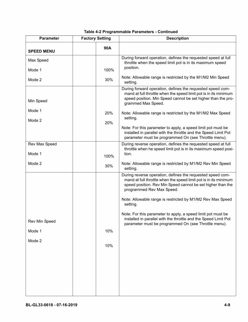
Table 4-2 Programmable Parameters - Continued
Parameter Factory Setting Description
90ASPEED MENU
Max Speed
Mode 1
Mode 2
100%
30%
During forward operation, defines the requested speed at full throttle when the speed limit pot is in its maximum speed position.
Note: Allowable range is restricted by the M1/M2 Min Speed setting.
Min Speed
Mode 1
Mode 2
20%
20%
During forward operation, defines the requested speed com-mand at full throttle when the speed limit pot is in its minimum speed position. Min Speed cannot be set higher than the pro-grammed Max Speed.
Note: Allowable range is restricted by the M1/M2 Max Speed setting.
Note: For this parameter to apply, a speed limit pot must be installed in parallel with the throttle and the Speed Limit Pot parameter must be programmed On (see Throttle menu).
Rev Max Speed
Mode 1
Mode 2
100%
30%
During reverse operation, defines the requested speed at full throttle when he speed limit pot is in its maximum speed posi-tion.
Note: Allowable range is restricted by M1/M2 Rev Min Speed setting.
Rev Min Speed
Mode 1
Mode 2
10%
10%
During reverse operation, defines the requested speed com-mand at full throttle when the speed limit pot is in its minimum speed position. Rev Min Speed cannot be set higher than the programmed Rev Max Speed.
Note: Allowable range is restricted by M1/M2 Rev Max Speed setting.
Note: For this parameter to apply, a speed limit pot must be installed in parallel with the throttle and the Speed Limit Pot parameter must be programmed On (see Throttle menu).
BL-GL33-0618 - 07-16-2019 4-9
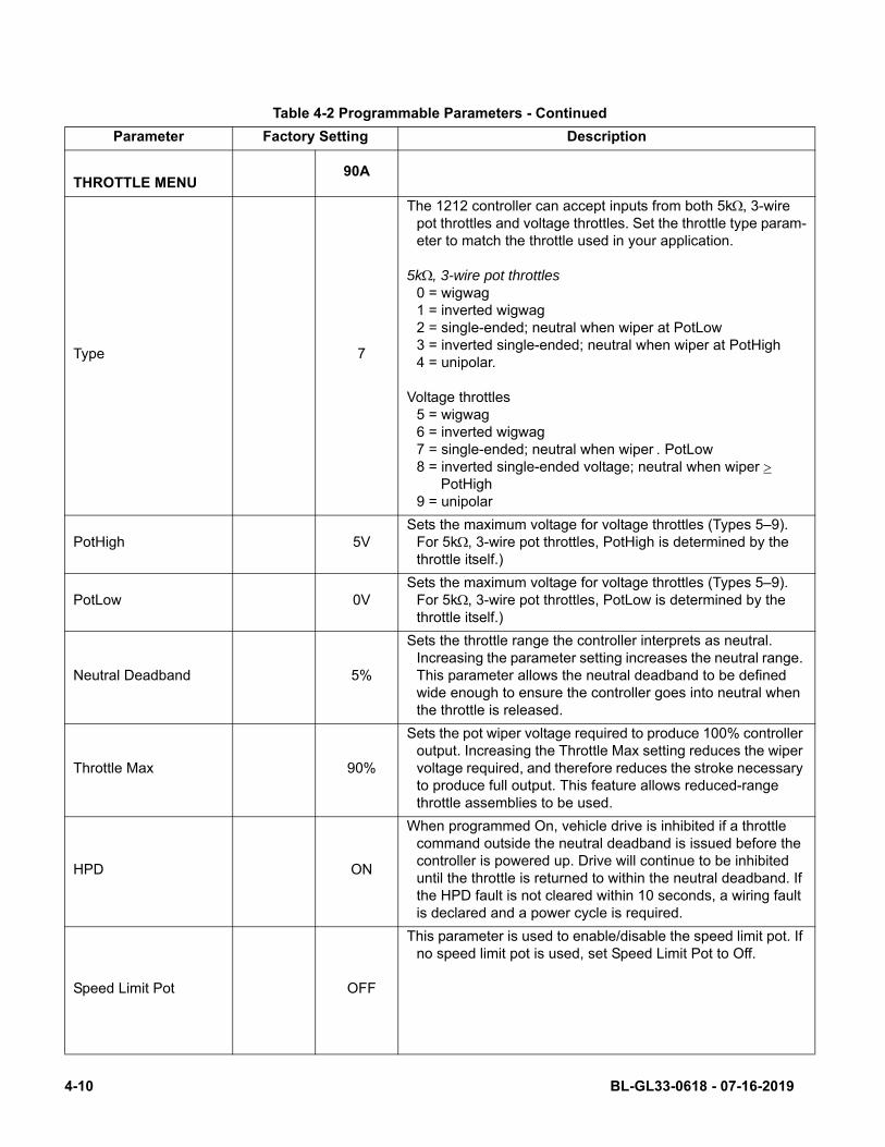
Table 4-2 Programmable Parameters - Continued
Parameter Factory Setting Description
90ATHROTTLE MENU
Type 7
The 1212 controller can accept inputs from both 5k, 3-wire pot throttles and voltage throttles. Set the throttle type param-eter to match the throttle used in your application.
5k, 3-wire pot throttles0 = wigwag1 = inverted wigwag2 = single-ended; neutral when wiper at PotLow3 = inverted single-ended; neutral when wiper at PotHigh4 = unipolar.
Voltage throttles5 = wigwag6 = inverted wigwag7 = single-ended; neutral when wiper PotLow8 = inverted single-ended voltage; neutral when wiper PotHigh9 = unipolar
PotHigh 5VSets the maximum voltage for voltage throttles (Types 5–9).
For 5k, 3-wire pot throttles, PotHigh is determined by the throttle itself.)
PotLow 0VSets the maximum voltage for voltage throttles (Types 5–9).
For 5k, 3-wire pot throttles, PotLow is determined by the throttle itself.)
Neutral Deadband 5%
Sets the throttle range the controller interprets as neutral. Increasing the parameter setting increases the neutral range. This parameter allows the neutral deadband to be defined wide enough to ensure the controller goes into neutral when the throttle is released.
Throttle Max 90%
Sets the pot wiper voltage required to produce 100% controller output. Increasing the Throttle Max setting reduces the wiper voltage required, and therefore reduces the stroke necessary to produce full output. This feature allows reduced-range throttle assemblies to be used.
HPD ON
When programmed On, vehicle drive is inhibited if a throttle command outside the neutral deadband is issued before the controller is powered up. Drive will continue to be inhibited until the throttle is returned to within the neutral deadband. If the HPD fault is not cleared within 10 seconds, a wiring fault is declared and a power cycle is required.
Speed Limit Pot OFF
This parameter is used to enable/disable the speed limit pot. If no speed limit pot is used, set Speed Limit Pot to Off.
4-10 BL-GL33-0618 - 07-16-2019
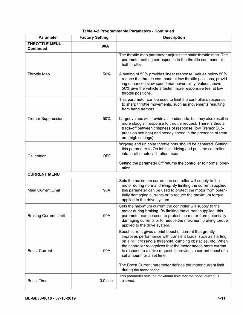
Table 4-2 Programmable Parameters - Continued
Parameter Factory Setting Description
THROTTLE MENU - Continued
90A
Throttle Map 50%
The throttle map parameter adjusts the static throttle map. The parameter setting corresponds to the throttle command at half throttle.
A setting of 50% provides linear response. Values below 50% reduce the throttle command at low throttle positions, provid-ing enhanced slow speed maneuverability. Values above 50% give the vehicle a faster, more responsive feel at low throttle positions.
Tremor Suppression 50%
This parameter can be used to limit the controller’s response to sharp throttle movements, such as movements resulting from hand tremors.
Larger values will provide a steadier ride, but they also result in more sluggish response to throttle request. There is thus a trade-off between crispness of response (low Tremor Sup-pression settings) and steady speed in the presence of trem-ors (high settings).
Calibration OFF
Wigwag and unipolar throttle pots should be centered. Setting this parameter to On inhibits driving and puts the controller into throttle autocalibration mode.
Setting the parameter Off returns the controller to normal oper-ation.
CURRENT MENU
Main Current Limit 90A
Sets the maximum current the controller will supply to the motor during normal driving. By limiting the current supplied, this parameter can be used to protect the motor from poten-tially damaging currents or to reduce the maximum torque applied to the drive system.
Braking Current Limit 90A
Sets the maximum current the controller will supply to the motor during braking. By limiting the current supplied, this parameter can be used to protect the motor from potentially damaging currents or to reduce the maximum braking torque applied to the drive system.
Boost Current 90A
Boost current gives a brief boost of current that greatly improves performance with transient loads, such as starting on a hill, crossing a threshold, climbing obstacles, etc. When the controller recognizes that the motor needs more current to respond to a drive request, it provides a current boost of a set amount for a set time.
The Boost Current parameter defines the motor current limit during the boost period
Boost Time 0.0 sec.This parameter sets the maximum time that the boost current is
allowed.
BL-GL33-0618 - 07-16-2019 4-11
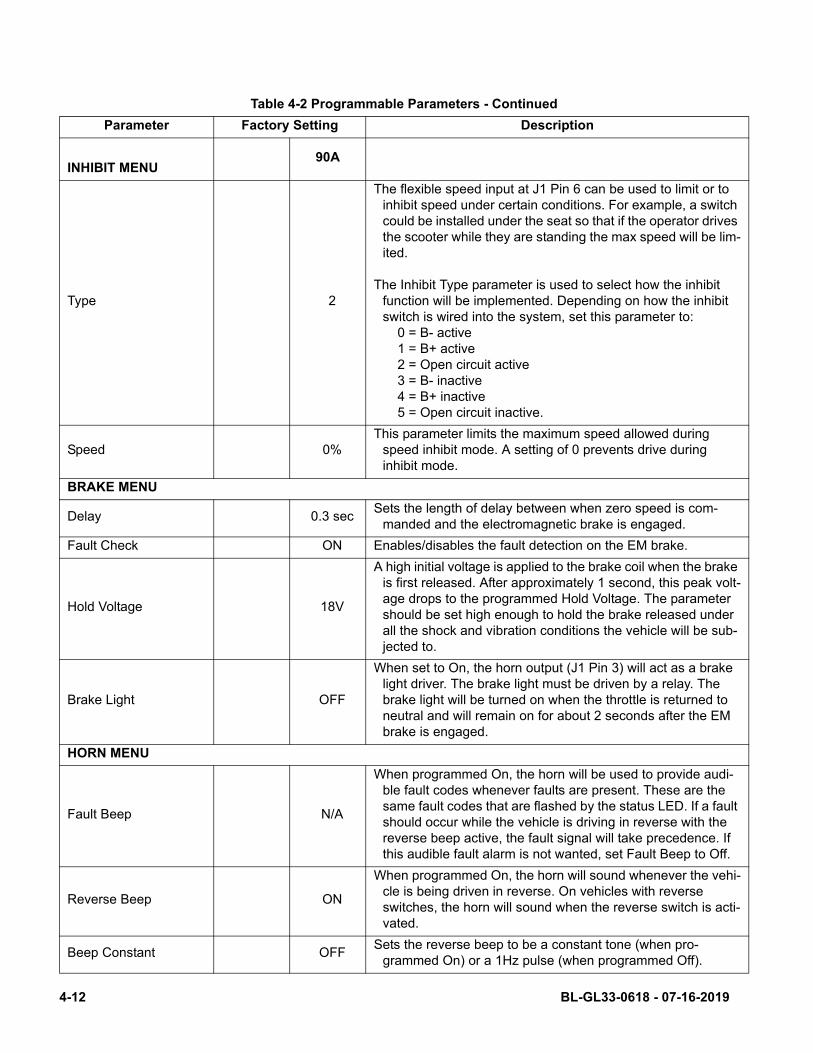
Table 4-2 Programmable Parameters - Continued
Parameter Factory Setting Description
90AINHIBIT MENU
Type 2
The flexible speed input at J1 Pin 6 can be used to limit or to inhibit speed under certain conditions. For example, a switch could be installed under the seat so that if the operator drives the scooter while they are standing the max speed will be lim-ited.
The Inhibit Type parameter is used to select how the inhibit function will be implemented. Depending on how the inhibit switch is wired into the system, set this parameter to: 0 = B- active 1 = B+ active 2 = Open circuit active 3 = B- inactive 4 = B+ inactive 5 = Open circuit inactive.
Speed 0%This parameter limits the maximum speed allowed during
speed inhibit mode. A setting of 0 prevents drive during inhibit mode.
BRAKE MENU
Delay 0.3 secSets the length of delay between when zero speed is com-
manded and the electromagnetic brake is engaged.
Fault Check ON Enables/disables the fault detection on the EM brake.
Hold Voltage 18V
A high initial voltage is applied to the brake coil when the brake is first released. After approximately 1 second, this peak volt-age drops to the programmed Hold Voltage. The parameter should be set high enough to hold the brake released under all the shock and vibration conditions the vehicle will be sub-jected to.
Brake Light OFF
When set to On, the horn output (J1 Pin 3) will act as a brake light driver. The brake light must be driven by a relay. The brake light will be turned on when the throttle is returned to neutral and will remain on for about 2 seconds after the EM brake is engaged.
HORN MENU
Fault Beep N/A
When programmed On, the horn will be used to provide audi-ble fault codes whenever faults are present. These are the same fault codes that are flashed by the status LED. If a fault should occur while the vehicle is driving in reverse with the reverse beep active, the fault signal will take precedence. If this audible fault alarm is not wanted, set Fault Beep to Off.
Reverse Beep ON
When programmed On, the horn will sound whenever the vehi-cle is being driven in reverse. On vehicles with reverse switches, the horn will sound when the reverse switch is acti-vated.
Beep Constant OFFSets the reverse beep to be a constant tone (when pro-
grammed On) or a 1Hz pulse (when programmed Off).
4-12 BL-GL33-0618 - 07-16-2019
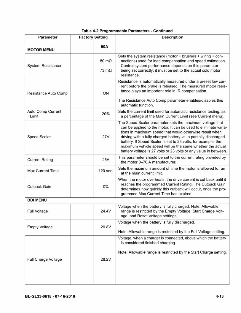
Table 4-2 Programmable Parameters - Continued
Parameter Factory Setting Description
90AMOTOR MENU
System Resistance80 mΩ
73 mΩ
Sets the system resistance (motor + brushes + wiring + con-nections) used for load compensation and speed estimation. Control system performance depends on this parameter being set correctly; it must be set to the actual cold motor resistance.
Resistance Auto Comp ON
Resistance is automatically measured under a preset low cur-rent before the brake is released. The measured motor resis-tance plays an important role in IR compensation.
The Resistance Auto Comp parameter enables/disables this automatic function.
Auto Comp Current Limit
20%Sets the current limit used for automatic resistance testing, as
a percentage of the Main Current Limit (see Current menu).
Speed Scaler 27V
The Speed Scaler parameter sets the maximum voltage that can be applied to the motor. It can be used to eliminate varia-tions in maximum speed that would otherwise result when driving with a fully charged battery vs. a partially discharged battery. If Speed Scaler is set to 23 volts, for example, the maximum vehicle speed will be the same whether the actual battery voltage is 27 volts or 23 volts or any value in between.
Current Rating 25AThis parameter should be set to the current rating provided by
the motor 0–70 A manufacturer.
Max Current Time 120 sec.Sets the maximum amount of time the motor is allowed to run
at the main current limit.
Cutback Gain 0%
When the motor overheats, the drive current is cut back until it reaches the programmed Current Rating. The Cutback Gain determines how quickly this cutback will occur, once the pro-grammed Max Current Time has expired.
BDI MENU
Full Voltage 24.4VVoltage when the battery is fully charged. Note: Allowable
range is restricted by the Empty Voltage, Start Charge Volt-age, and Reset Voltage settings.
Empty Voltage 20.8VVoltage when the battery is fully discharged.
Note: Allowable range is restricted by the Full Voltage setting.
Full Charge Voltage 28.2V
Voltage, when a charger is connected, above which the battery is considered finished charging.
Note: Allowable range is restricted by the Start Charge setting.
BL-GL33-0618 - 07-16-2019 4-13

Table 4-2 Programmable Parameters - Continued
Parameter Factory Setting Description
BDI MENU - Cont. 90A
Start Charger Voltage
25.2V
Voltage above which the battery is considered to start charging.
Note: Allowable range is restricted by the Full Voltage and Full Charge Voltage settings.
Reset Voltage 25.0VVoltage at which the BDI calculator will be reset to 100%, after
the charger is disconnected and the controller is powered up.
Note: Allowable range is restricted by the Full Voltage setting.
Discharge Factor 2.0Discharge rate of the battery. Larger values are for larger bat-
teries, which discharge more slowly.
Charge Factor 2.0Charge rate of the battery. Larger values are for larger batter-
ies, which charge more slowly.
Low BDI Level 40%
Sets the battery charge level at which maximum vehicle speed will be limited in order to protect the battery from deep dis-charge. Setting Low BDI Level to zero disables this function and allows the battery to discharge completely.
Low BDI Max Speed 15%Sets the maximum allowed vehicle speed when the battery
charge falls below the programmed Low BDI Level.
COMPENSATION MENU
IR Comp 70%
Sets the motor load compensation. Higher values provide stronger disturbance rejection, while lower values provide smoother operation.
Note: Allowable range is restricted by the Anti-Rollback Comp setting.
Anti-Rollback Comp 90%
Sets the motor load compensation after the throttle is released to neutral and the speed is estimated to be near zero. Higher values provide more hill-holding force.
Note: Allowable range is restricted by the IR Comp setting.
4-14 BL-GL33-0618 - 07-16-2019
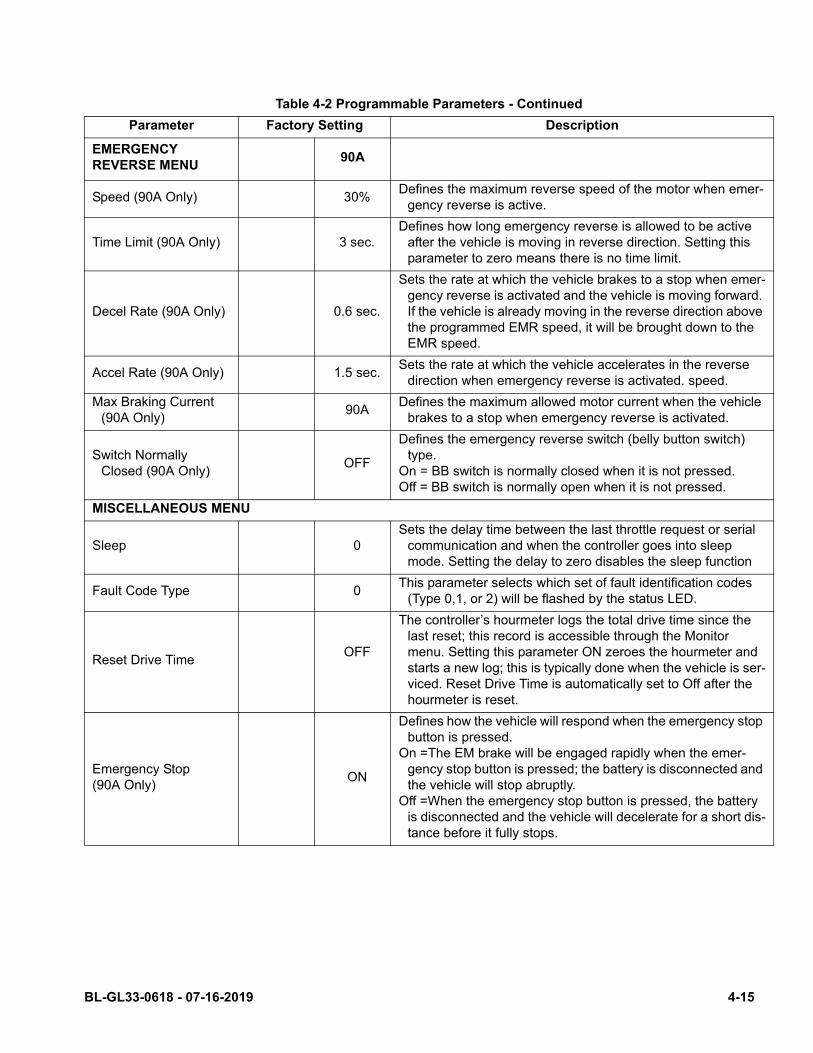
Table 4-2 Programmable Parameters - Continued
Parameter Factory Setting Description
EMERGENCY REVERSE MENU
90A
Speed (90A Only) 30%Defines the maximum reverse speed of the motor when emer-
gency reverse is active.
Time Limit (90A Only) 3 sec.Defines how long emergency reverse is allowed to be active
after the vehicle is moving in reverse direction. Setting this parameter to zero means there is no time limit.
Decel Rate (90A Only) 0.6 sec.
Sets the rate at which the vehicle brakes to a stop when emer-gency reverse is activated and the vehicle is moving forward. If the vehicle is already moving in the reverse direction above the programmed EMR speed, it will be brought down to the EMR speed.
Accel Rate (90A Only) 1.5 sec.Sets the rate at which the vehicle accelerates in the reverse
direction when emergency reverse is activated. speed.
Max Braking Current (90A Only)
90ADefines the maximum allowed motor current when the vehicle
brakes to a stop when emergency reverse is activated.
Switch Normally Closed (90A Only)
OFF
Defines the emergency reverse switch (belly button switch) type.
On = BB switch is normally closed when it is not pressed.Off = BB switch is normally open when it is not pressed.
MISCELLANEOUS MENU
Sleep 0Sets the delay time between the last throttle request or serial
communication and when the controller goes into sleep mode. Setting the delay to zero disables the sleep function
Fault Code Type 0This parameter selects which set of fault identification codes
(Type 0,1, or 2) will be flashed by the status LED.
Reset Drive TimeOFF
The controller’s hourmeter logs the total drive time since the last reset; this record is accessible through the Monitor menu. Setting this parameter ON zeroes the hourmeter and starts a new log; this is typically done when the vehicle is ser-viced. Reset Drive Time is automatically set to Off after the hourmeter is reset.
Emergency Stop (90A Only)
ON
Defines how the vehicle will respond when the emergency stop button is pressed.
On =The EM brake will be engaged rapidly when the emer-gency stop button is pressed; the battery is disconnected and the vehicle will stop abruptly.
Off =When the emergency stop button is pressed, the battery is disconnected and the vehicle will decelerate for a short dis-tance before it fully stops.
BL-GL33-0618 - 07-16-2019 4-15
4-2.8. Programmer Diagnostics
With a programmer, diagnostics and troubleshooting ismore direct than with the LED alone. The programmerpresents complete diagnostic information in plain lan-guage - no code to decipher. Faults are displayed inthe Diagnostic Menu, and the status of the controllerinputs/outputs is displayed in the Test Menu.
The following 4-step process is generally used fordiagnosing and troubleshooting an inoperative vehicleusing the programmer:
1. Visually inspect the vehicle for obvious problems:
2. Diagnose the problem:
3. Test the circuitry with the programmer:
4. Correct the problem.
Repeat the last three steps as necessary until thevehicle is operational.
Refer to the Table 4-3 for suggestions covering awide range of possible faults.
4-16 BL-GL33-0618 - 07-16-2019
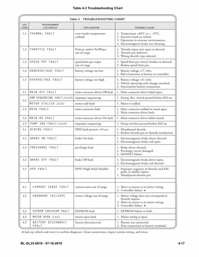
Table 4-3 Troubleshooting Chart
BL-GL33-0618 - 07-16-2019 4-17
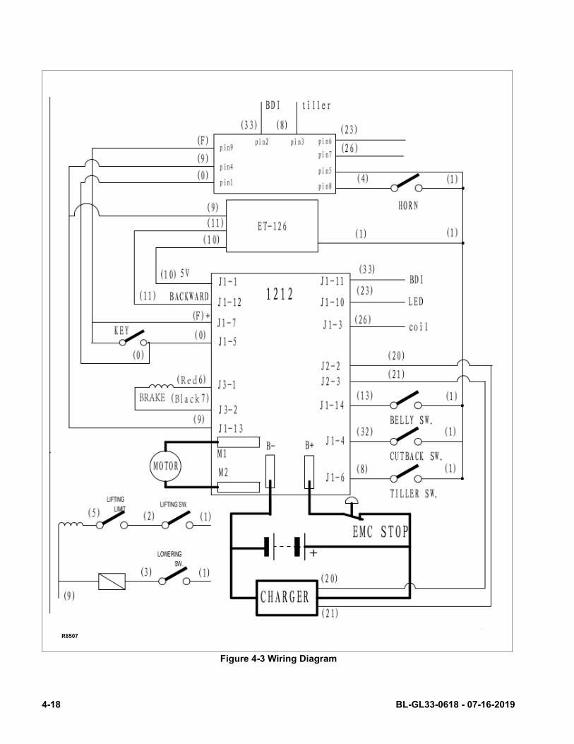
Figure 4-3 Wiring Diagram
R8507
4-18 BL-GL33-0618 - 07-16-2019

SECTION 5STEERING ARM, CONTROL HEAD AND COMPARTMENT
5-1. CONTROL HEAD
5-1.1. Control Head Removal
1. Turn off the key switch and emergency discon-nect.
2. Remove the control head Covers as described inparagraph 5-1.3.
3. Disconnect harness from potentiometer.
Figure 5-1 Steering Arm
GL33-1
BL-GL33-0618 - 07-16-2019 5-1
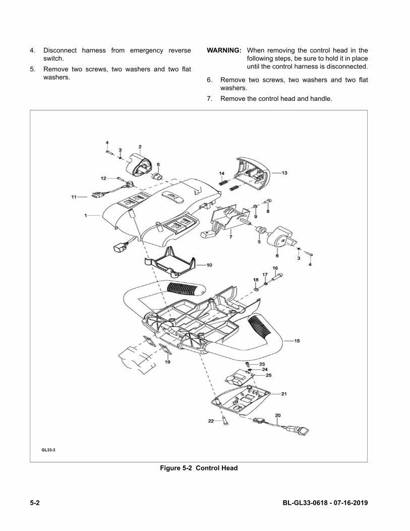
4. Disconnect harness from emergency reverseswitch.
5. Remove two screws, two washers and two flatwashers.
WARNING: When removing the control head in thefollowing steps, be sure to hold it in placeuntil the control harness is disconnected.
6. Remove two screws, two washers and two flatwashers.
7. Remove the control head and handle.
Figure 5-2 Control Head
GL33-3
5-2 BL-GL33-0618 - 07-16-2019
5-1.2. Control Head Installation
1. Secure control head and handle with two screws,two washers and two flat washers.
2. Install two screws, two washers and two flatwashers.
3. Reconnect harness to emergency reverse switch.
4. Reconnect harness to potentiometer.
5. Install the control Head Covers as described inparagraph 5-1.4.
6. Turn on the key switch and emergency discon-nect.
5-1.3. Control Head Covers Removal.
1. Turn off the key switch and emergency discon-nect.
2. Remove four screws and lift up control head Cov-ers.
3. Disconnect harnesses from each other andremove control head Covers.
5-1.4. Control Head Covers Installation.
1. Hold control head Covers in place and connectharnesses together.
2. Position control Head Covers on control head andsecure with four screws.
3. Turn on the key switch and emergency discon-nect.
5-1.5. Speed Potentiometer Replacement.
1. Remove the control Head Covers as described inparagraph 5-1.3.
2. Disconnect harness from potentiometer.
3. Remove screw, washer and control knob frompotentiometer.
4. Remove screw, washer and control knob fromother side of potentiometer.
BL-GL33-0618 - 07-16-2019 5-3
5. Remove screws, two lock washers and two flatwashers and remove potentiometer and switchassembly from bracket.
6. Position new potentiometer and switch assemblyin bracket and secure with screw, screw, two lockwashers and two flat washers.
7. Install control knob on potentiometer and securewith screw, and washer.
8. Install control knob on the other side of potentiom-eter and secure with screw, and washer.
9. Reconnect harness to potentiometer.
10. Install the control Head Covers as described inparagraph 5-1.4.
5-1.6. Belly-Button Switch Replacement.
1. Remove the control Head Covers as described inparagraph 5-1.3.
2. Disconnect harness from emergency disconnectswitch.
3. Remove screws, two lock washers and two flatwashers and remove potentiometer and switchassembly from bracket.
4. Remove pin, bracket, and spring from button.
5. Remove two pins and switch assembly frombracket.
6. Position the new switch assembly in bracket andsecure with two pins.
7. Position bracket and springs in button and installpin.
8. Position potentiometer and switch assembly inbracket and secure with screws, two lock washersand two flat washers.
9. Reconnect harness to emergency reverse switch.
10. Install the control head Covers as described inparagraph 5-1.4.
5-4 BL-GL33-0618 - 07-16-2019

Figure 5-3 Emergency Reverse Switch Assembly
5-1.7. Horn Switch Replacement.
1. Remove the control head Covers as described inparagraph 5-1.3.
2. Remove three screws, bracket and two springs.
3. Remove two pins and switch from bracket.
4. Position new switch in bracket and secure withtwo pins.
5. Position bracket with two springs in cover andsecure with three screws.
6. Install the control head Covers as described inparagraph 5-1.4.
GL33-3
BL-GL33-0618 - 07-16-2019 5-5
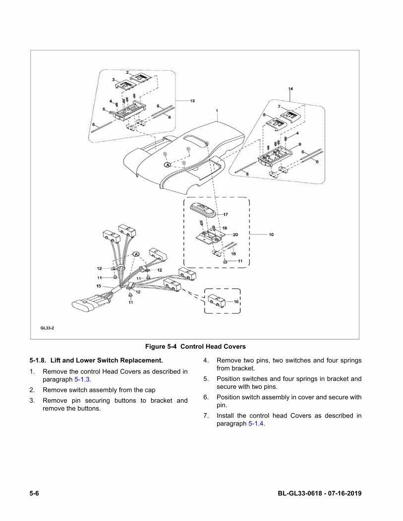
Figure 5-4 Control Head Covers
5-1.8. Lift and Lower Switch Replacement.
1. Remove the control Head Covers as described inparagraph 5-1.3.
2. Remove switch assembly from the cap
3. Remove pin securing buttons to bracket andremove the buttons.
4. Remove two pins, two switches and four springsfrom bracket.
5. Position switches and four springs in bracket andsecure with two pins.
6. Position switch assembly in cover and secure withpin.
7. Install the control head Covers as described inparagraph 5-1.4.
GL33-2
5-6 BL-GL33-0618 - 07-16-2019

5-2. UPPER COMPARTMENT COVERS
5-2.1. Removal.
1. Turn off the key switch and emergency discon-nect.
2. Pull cable up and remove cap from the cable. Letcable back down into cover.
3. Remove two screws and cover.
4. Disconnect cable from the battery charger.
5-2.2. Installation.
1. Reconnect cable to the battery charger.
2. Feed cable through cover and position cover onframe. Secure with two screws.
3. Install cap on cable and position the cap on cover.
4. Turn on the key switch and emergency discon-nect.
Figure 5-5 Compartment Cover
GL33-5
BL-GL33-0618 - 07-16-2019 5-7

5-3. LOWER COMPARTMENT COVERS
5-3.1. Removal.
1. Turn off the key switch and emergency discon-nect.
2. Remove four screws and washers from lowercover.
3. Remove lower cover from back frame.
5-3.2. Installation.
1. Position lower cover on back frame and securewith four screws and washers.
2. Turn on the key switch and emergency discon-nect.
Figure 5-6 Steering Arm
GL33-1
5-8 BL-GL33-0618 - 07-16-2019
5-4. STEERING ARM
5-4.1. Return Spring Replacement.
The steering arm gas return spring is replaced whilethe steering arm is in the upright position.
1. Secure the steering arm in the upright position.
2. Remove screw and free the gas return springfrom bracket.
3. Pull downward on the gas return spring to free itfrom its seat inside steering arm.
4. Position the new gas return spring inside thesteering arm being sure it fully engages its seat.
5. Position the opposite end of the gas return springon bracket and install screw.
5-4.2. Steering Arm Removal.
1. Remove steering arm gas return spring asdescribed in paragraph 5-4.1.
2. Disconnect the harnesses from each other.
3. Attach a hoist to steering arm.
4. Remove shaft and the steering arm.
5-4.3. Steering Arm Installation.
1. Position steering arm over bracket and securewith shaft.
2. Reconnect harnesses to each other.
3. Install steering arm gas return spring as describedin paragraph 5-4.1.
BL-GL33-0618 - 07-16-2019 5-9

5-10 BL-GL33-0618 - 07-16-2019
SECTION 6BRAKE SERVICING
6-1. BRAKES.
The brake system consists of a transmission mountedbrake. This brake is spring applied and electricallyreleased.
6-1.1. Brake Assembly Replacement
1. Block load wheels.
2. Remove the lower compartment covers asdescribed in paragraph 5-3.
3. Disconnect electric brake from harness.
4. Remove the three mounting screws and thebrake.
5. Place the new brake into position and secure withthe three mounting screws.
6. Reconnect electric brake to harness.
7. Remove load wheel blocks and check operation.
8. Install the lower compartment covers asdescribed in paragraph 5-3.
BL-GL33-0618 - 07-16-2019 6-1
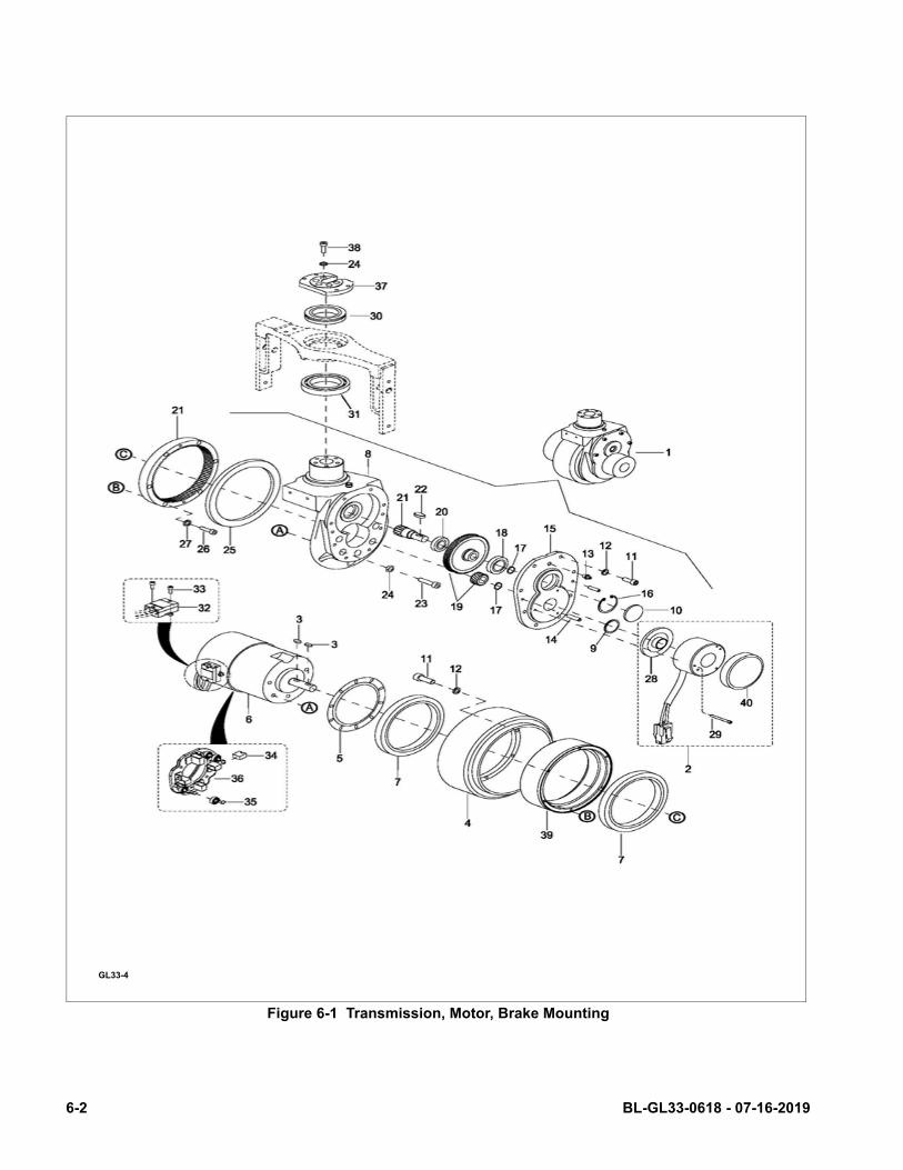
Figure 6-1 Transmission, Motor, Brake Mounting
GL33-4
6-2 BL-GL33-0618 - 07-16-2019
SECTION 7TRANSMISSION, DRIVE WHEEL, LOAD WHEEL
7-1. DRIVE WHEEL.
1. Turn off the key switch and emergency discon-nect.
2. Remove the lower compartment covers asdescribed in paragraph 5-3.
3. Jack up the truck so the drive wheel is off theground; then securely block the truck to preventmovement.
4. Disconnect cables from drive motor.
5. Remove screws, lock washers, and free motorwith drive wheel from housing.
6. Remove the screws, lock washers and gear.
7. Remove drive wheel from motor.
8. Remove bearing from wheel.
9. Install new drive wheel in reverse order ofremoval.
10. Install the lower compartment covers asdescribed in paragraph 5-3.
11. Turn on the key switch and emergency discon-nect.
7-2. TRANSMISSION.
1. Turn off the key switch and emergency discon-nect.
2. Remove the lower compartment covers asdescribed in paragraph 5-3.
3. Remove the brake as described in paragraph 6-1.1.
4. Remove the steering arm as described in para-graph 5-4.2.
5. Remove two screws and plate.
6. Remove five screws, five lock washers that holdsthe transmission to the back frame.
7. Remove the transmission.
8. Install new transmission by reversing the stepsabove.
BL-GL33-0618 - 07-16-2019 7-1
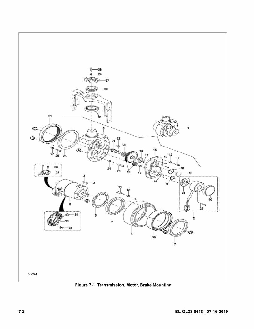
Figure 7-1 Transmission, Motor, Brake Mounting
GL-33-4
7-2 BL-GL33-0618 - 07-16-2019
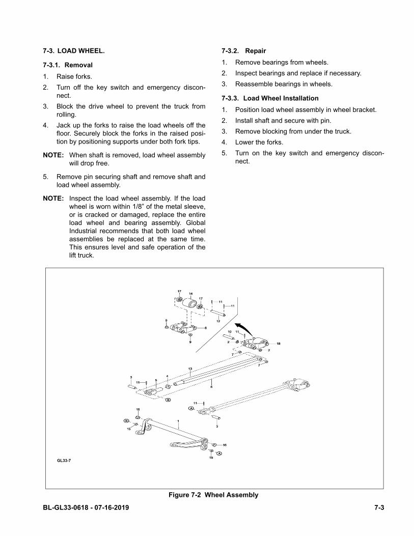
7-3. LOAD WHEEL.
7-3.1. Removal
1. Raise forks.
2. Turn off the key switch and emergency discon-nect.
3. Block the drive wheel to prevent the truck fromrolling.
4. Jack up the forks to raise the load wheels off thefloor. Securely block the forks in the raised posi-tion by positioning supports under both fork tips.
NOTE: When shaft is removed, load wheel assemblywill drop free.
5. Remove pin securing shaft and remove shaft andload wheel assembly.
NOTE: Inspect the load wheel assembly. If the loadwheel is worn within 1/8” of the metal sleeve,or is cracked or damaged, replace the entireload wheel and bearing assembly. GlobalIndustrial recommends that both load wheelassemblies be replaced at the same time.This ensures level and safe operation of thelift truck.
7-3.2. Repair
1. Remove bearings from wheels.
2. Inspect bearings and replace if necessary.
3. Reassemble bearings in wheels.
7-3.3. Load Wheel Installation
1. Position load wheel assembly in wheel bracket.
2. Install shaft and secure with pin.
3. Remove blocking from under the truck.
4. Lower the forks.
5. Turn on the key switch and emergency discon-nect.
Figure 7-2 Wheel Assembly
GL33-7
BL-GL33-0618 - 07-16-2019 7-3

NOTES
7-4 BL-GL33-0618 - 07-16-2019
SECTION 8ELEVATION SYSTEM SERVICING
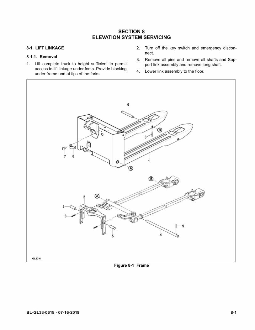
8-1. LIFT LINKAGE
8-1.1. Removal
1. Lift complete truck to height sufficient to permitaccess to lift linkage under forks. Provide blockingunder frame and at tips of the forks.
2. Turn off the key switch and emergency discon-nect.
3. Remove all pins and remove all shafts and Sup-port link assembly and remove long shaft.
4. Lower link assembly to the floor.
Figure 8-1 Frame
GL33-6
BL-GL33-0618 - 07-16-2019 8-1
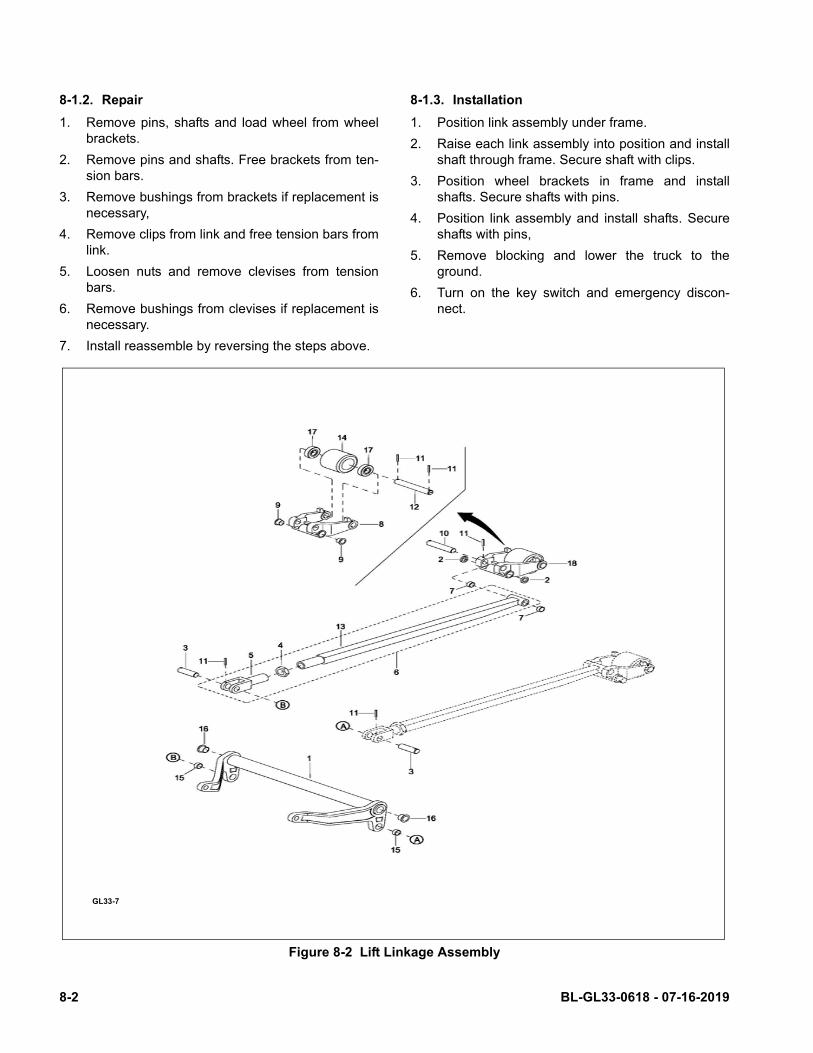
8-1.2. Repair
1. Remove pins, shafts and load wheel from wheelbrackets.
2. Remove pins and shafts. Free brackets from ten-sion bars.
3. Remove bushings from brackets if replacement isnecessary,
4. Remove clips from link and free tension bars fromlink.
5. Loosen nuts and remove clevises from tensionbars.
6. Remove bushings from clevises if replacement isnecessary.
7. Install reassemble by reversing the steps above.
8-1.3. Installation
1. Position link assembly under frame.
2. Raise each link assembly into position and installshaft through frame. Secure shaft with clips.
3. Position wheel brackets in frame and installshafts. Secure shafts with pins.
4. Position link assembly and install shafts. Secureshafts with pins,
5. Remove blocking and lower the truck to theground.
6. Turn on the key switch and emergency discon-nect.
Figure 8-2 Lift Linkage Assembly
GL33-7
8-2 BL-GL33-0618 - 07-16-2019

SECTION 9HYDRAULIC SYSTEM SERVICING
9-1. LINES AND FITTINGS
WARNING: When forks are raised, pressure exists inthe hydraulic system lines and fittings. Toensure release of pressure, forks mustbe fully lowered before performing anymaintenance on the hydraulic system.
NOTE: Leaking hydraulic fittings may be remedied bysimply tightening fittings. If this does not rem-edy the leak, the fittings or line must bereplaced.
1. Lower forks fully.
2. Turn off the key switch and emergency discon-nect.
3. Remove the upper compartment cover asdescribed in paragraph 5-2.
Figure 9-1 Compartment Cover
GL33-5
BL-GL33-0618 - 07-16-2019 9-1
CAUTION: Hydraulic oil can damage parts. Wipe offany oil immediately. Provide a containerunder the line or fitting before discon-necting.
4. Refer to Figure 9-2 and remove leaking line or fit-ting and replace it with a new line or fitting. Checklevel of hydraulic oil. With lift carriage fully low-ered, fill reservoir with hydraulic oil to 1 inch belowopening. Use hydraulic oil listed in Table 3-2.
5. Turn on the key switch and emergency discon-nect.
6. Operate the lift and lower buttons to refill the cylinder and lines with hydraulic oil.
7. Check level of hydraulic oil. Hydraulic oil must be1 inch below opening. If required, add hydraulicoil to bring to proper level. Use hydraulic oil listedin Table 3-2.
8. Install the upper compartment cover as describedin paragraph 5-2.
9-2. HYDRAULIC AND ELECTRICAL ASSEMBLYREMOVAL
The hydraulic system and electrical system can beremoved as an assembly to provide additional clear-ance for various maintenance procedures.
WARNING: When forks are raised, pressure exists inthe hydraulic system lines and fittings. Toensure release of pressure, forks mustbe fully lowered and the batteries discon-nected before performing any mainte-nance on the hydraulic system.
9-2.1. Removal
1. Lower forks fully.
2. Turn off the key switch and emergency discon-nect.
3. Remove the upper compartment cover asdescribed in paragraph 5-2.
4. Remove the hydraulic line from the pump assem-bly.
5. Disconnect the wires and cables from the charger,and hydraulic system.
6. Remove the 4 (5mm) screws and washers to liftassembly away from frame.
9-2.2. Installation
1. Position assembly on frame and secure withscrews and washers.
2. Assemble in reverse order.
3. Turn on the key switch and emergency discon-nect.
4. Install the upper compartment cover as describedin paragraph 5-2.
9-3. HYDRAULIC PUMP, MOTOR, AND RESER-VOIR ASSY
The hydraulic pump/motor assembly can be disas-sembled and repaired. However, a defective pump,valve or motor requires replacement of that compo-nent.
WARNING: When forks are raised, pressure exists inthe hydraulic system lines and fittings. Toensure release of pressure, forks mustbe fully lowered and the batteries discon-nected before performing any mainte-nance on the hydraulic system.
9-3.1. Removal
1. Lower forks fully.
2. Turn off the key switch and emergency discon-nect.
3. Remove the hydraulic and electrical assembly asdescribed in paragraph 9-2.1.
4. Tag and disconnect electrical leads from solenoidand motor.
NOTE: The reservoir and hose will be filled withhydraulic oil. Place a container under thepump assembly to catch any hydraulic oil.
5. Disconnect hose from the pump and motorassembly.
6. Remove two screws and washers then removethe pump and motor assembly.
9-3.2. Disassembly and Reassembly
1. Remove the hydraulic pump/motor assembly asdescribed in paragraph 9-3.1.
2. Refer to Figure 9-3 for disassembly and reassem-bly.
9-3.3. Installation
1. Position pump and motor on bracket and securewith two screws and washers.
2. Connect electrical leads to motor and solenoid.
3. Reconnect hose to the pump and motor assemblywith two washers and bolt.
9-2 BL-GL33-0618 - 07-16-2019
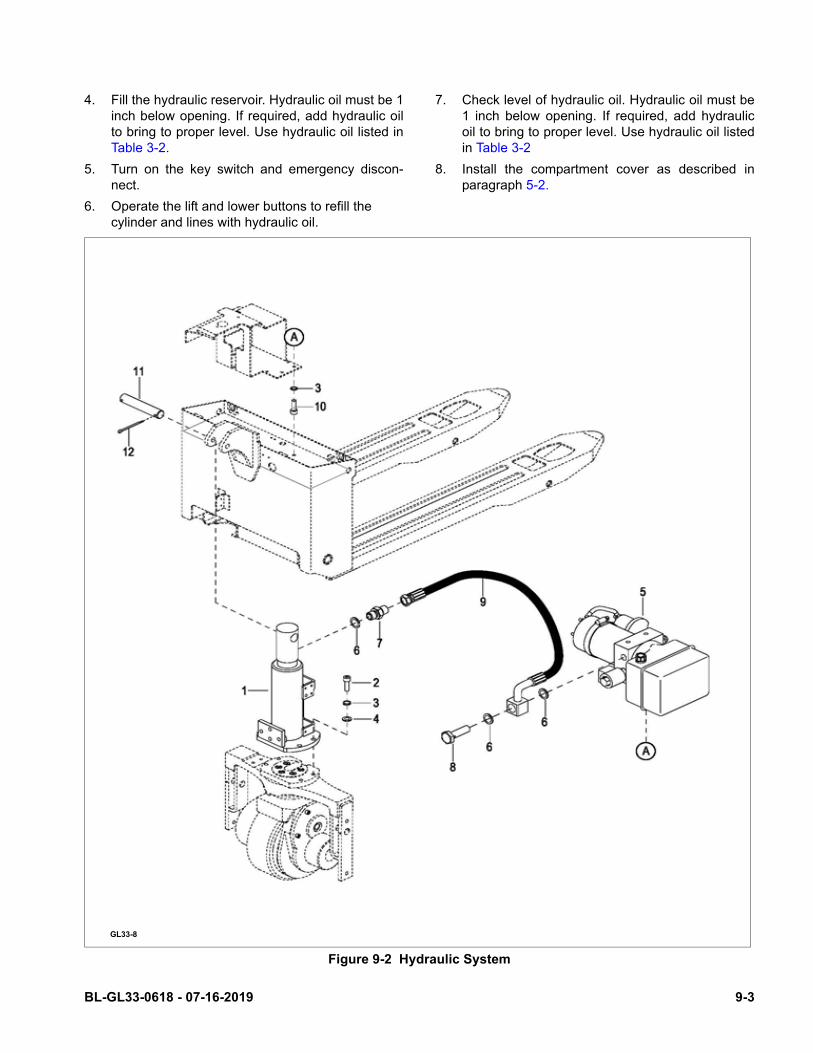
4. Fill the hydraulic reservoir. Hydraulic oil must be 1inch below opening. If required, add hydraulic oilto bring to proper level. Use hydraulic oil listed inTable 3-2.
5. Turn on the key switch and emergency discon-nect.
6. Operate the lift and lower buttons to refill the cylinder and lines with hydraulic oil.
7. Check level of hydraulic oil. Hydraulic oil must be1 inch below opening. If required, add hydraulicoil to bring to proper level. Use hydraulic oil listedin Table 3-2
8. Install the compartment cover as described inparagraph 5-2.
Figure 9-2 Hydraulic System
GL33-8
BL-GL33-0618 - 07-16-2019 9-3

Figure 9-3 Pump & Motor Assy
GL33-9
9-4 BL-GL33-0618 - 07-16-2019

9-4. LIFT CYLINDER
9-4.1. Removal
1. Lower forks fully.
2. Turn off the key switch and emergency discon-nect.
3. Remove the upper compartment covers asdescribed in paragraph 5-2.
4. Ensure that hydraulic pressure has been relievedfrom the lift circuit. Disconnect the hydraulic linefrom the lift cylinder.
5. Remove the 4 screws that secure the Aluminumhousing to the cylinder.
6. Remove the handle assembly by removing the 3mounting screws at the base of the handle andremove the handle.
7. Remove the shaft and pin and disconnect hosefrom cylinder.
8. Remove screws and washers securing the cylin-der to frame.
WARNING: Frame is heavy. Use care while securingand lifting in order to prevent injury.
9. With suitable hoist, carefully raise frame slightlyso the cylinder can be removed.
9-4.2. Repair
1. Secure the lift cylinder in a vise, clamping lightlyat the base of the cylinder.
2. Remove wiper and O-ring from gland nut.
3. Withdraw the cylinder rod from body.
4. Remove guide ring and seal ring from rod.
NOTE: If the cylinder body or piston rod are dam-aged, the entire lift cylinder must be replaced.
5. Replace guide ring, seal ring, wiper ring and O-ring.
6. Coat all parts with hydraulic oil (Table 3-2).
7. Install new guide ring and seal ring on rod.
8. Insert piston rod into body.
Figure 9-4 Lift Cylinder
GL33-10
BL-GL33-0618 - 07-16-2019 9-5

9-4.3. Installation
1. Position the cylinder on frame and secure withscrews and washers. Then lower the frame ontothe cylinder.
2. Reconnect the hose to cylinder.
3. Fill the hydraulic reservoir. Hydraulic oil must be 1inch below opening. If required, add hydraulic oilto bring to proper level. Use hydraulic oil listed inTable 3-2.
4. Turn on the key switch and emergency discon-nect.
5. Operate the lift and lower buttons to refill the cylinder and lines with hydraulic oil.
6. Check level of hydraulic oil. Hydraulic oil must be1 inch below opening. If required, add hydraulicoil to bring to proper level. Use hydraulic oil listedin Table 3-2.
7. Install the compartment cover as described inparagraph 5-2.
9-6 BL-GL33-0618 - 07-16-2019

SECTION 10ELECTRICAL COMPONENTS
10-1.ELECTRICAL CONTROL PANEL
10-1.1.Maintenance
NOTE: Erratic operation of the truck may be causedby defective controller components. Beforeremoving the electrical panel, perform trou-bleshooting procedures per SECTION 4, todetermine corrective action to be taken.
There are no user-serviceable parts inside the control-ler. No attempt should be made to open the controller.Opening the controller may damage it and will void thewarranty.
The controller is programmed at the factory specifi-cally for the truck model on which it is equipped. It isimportant to replace the controller with the correct pre-programmed unit to assure proper performance set-tings intended for that particular truck. See theElectrical System in the parts section for the prepro-grammed controller part number.
It is recommended that the controller exterior becleaned periodically, and if a Curtis Handset is avail-able, this periodic cleaning provides a good opportu-nity to check the controller’s diagnostic history file. It isalso recommended that the controller’s fault detectioncircuitry be checked whenever the vehicle is serviced.
10-1.2.Cleaning
1. Turn off the key switch and emergency discon-nect.
2. Remove the upper compartment covers asdescribed in paragraph 5-2.
3. Remove any dirt or corrosion from the bus bararea. The controller should be wiped clean with amoist rag. Allow it to dry before reconnecting thebattery.
4. Make sure the connections to the buss bars aretight. Use two well insulated wrenches for thistask in order to avoid steering the buss bars.
10-1.3.Controller Removal.
1. Turn off the key switch and emergency discon-nect.
2. Remove the upper compartment covers asdescribed in paragraph 5-2.
3. Tag and disconnect harness from controller.
4. Remove two screws, two lock washers andremove controller and heat sink from bracket.
10-1.4.Controller Installation.
1. Position controller and heat sink on bracket andsecure with two screws and two lock washers.
2. Reconnect harness to controller.
3. Install upper compartment covers as described inparagraph 5-2.
4. Turn on the key switch and emergency discon-nect.
10-1.5.Charger Removal.
1. Turn off the key switch and emergency discon-nect.
2. Remove the upper compartment covers asdescribed in paragraph 5-2.
3. Tag and disconnect harness from charger.
4. Tag and disconnect remaining two charger leadsfrom the pump motor and the fuse. Refer to Fig-ure 10-3.
5. Remove four screws and four lock washers.Remove charger from bracket.
10-1.6.Charger Installation.
1. Position charger on bracket and secure with fourscrews and four lock washers.
2. Reconnect the two charger leads to the pumpmotor and the fuse. Refer to Figure 10-3.
3. Reconnect harness to charger.
4. Install upper compartment covers as described inparagraph 5-2.
5. Turn on the key switch and emergency discon-nect.
BL-GL33-0618 - 07-16-2019 10-1

Figure 10-1 Electrical System
GL33-11
10-2 BL-GL33-0618 - 07-16-2019

10-1.7.Buzzer Removal.
1. Turn off the key switch and emergency discon-nect.
2. Remove the upper rear cover from the back of thehandle, and remove the Power Module / buzzer.
10-1.8.Buzzer Installation.
1. Position buzzer on bracket and secure with onescrew.
2. Reconnect harness to buzzer.
3. Reassemble the upper compartment covers.
4. Turn on the key switch and emergency discon-nect.
10-1.9.Key Switch Removal.
1. Turn off the key switch and emergency discon-nect.
2. Remove the upper rear cover from the back of thehandle, and remove the Power Module / buzzer
3. Remove mounting nut and key switch frombracket.
10-1.10.Key Switch Installation.
1. Position key switch on bracket and secure with itsmounting nut.
2. Reconnect harness to key switch.
3. Reassemble the upper compartment covers asneeded.
4. Turn on the key switch and emergency discon-nect.
10-1.11.Battery Indicator Removal.
1. Turn off the key switch and emergency discon-nect.
2. Remove the upper compartment covers.
3. Tag and disconnect harness from battery indica-tor.
4. Remove the upper rear cover from the back of thehandle, and remove the Power Module / buzzer.
10-1.12.Battery Indicator Installation.
1. Position the Power Module / buzzer on bracket (6)and secure with its mounting bracket and nuts.
2. Reconnect harness to battery indicator.
3. Install upper compartment cover as required.
4. Turn on the key switch and emergency discon-nect.
10-1.13.Emergency Disconnect Removal.
1. Turn off the key switch, Push Down on the Emer-gency Stop Button and twist it Counter Clockwisewhile pushing down, then lift the knob off.
2. Tag and disconnect the cables harness fromemergency disconnect.
3. Remove two screws and remove emergency dis-connect from bracket.
4. Assemble in reverse order.
BL-GL33-0618 - 07-16-2019 10-3

10-1.14.Emergency Disconnect Installation.
1. Position emergency disconnect on bracket andsecure with two screws and washers.
2. Install the knob on the emergency disconnect.
3. Reconnect harness to emergency disconnect.
4. Install upper compartment covers as described inparagraph 5-2.
5. Turn on the key switch and emergency discon-nect.
Figure 10-2 Wiring Harness
GL33-12
10-4 BL-GL33-0618 - 07-16-2019
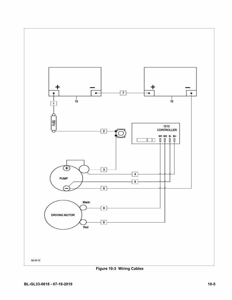
Figure 10-3 Wiring Cables
GL33-13
BL-GL33-0618 - 07-16-2019 10-5
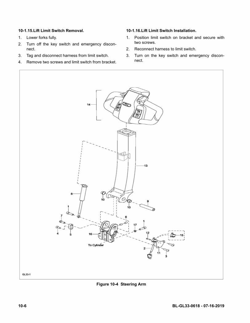
10-1.15.Lift Limit Switch Removal.
1. Lower forks fully.
2. Turn off the key switch and emergency discon-nect.
3. Tag and disconnect harness from limit switch.
4. Remove two screws and limit switch from bracket.
10-1.16.Lift Limit Switch Installation.
1. Position limit switch on bracket and secure withtwo screws.
2. Reconnect harness to limit switch.
3. Turn on the key switch and emergency discon-nect.
Figure 10-4 Steering Arm
GL33-1
10-6 BL-GL33-0618 - 07-16-2019
10-2.PUMP MOTOR.
The pump motor is replaceable but not repairable.Refer to paragraph 9-3.
10-3.DRIVE MOTOR.
The drive motor exposed surfaces should be cleanedat least once a month to assure proper cooling ofmotor. Use an air hose to blow dust off of motor sur-faces.
The drive motor is replaceable but not repairable.
10-4.DEADMAN SWITCH
10-4.1.Replacement
1. Turn off the key switch and emergency discon-nect.
2. Remove the upper compartment covers asdescribed in paragraph 5-2.
1. Disconnect wiring from the deadman switch.
2. Remove the two screws, and bracket frombracket.
3. Remove two screws and switch from bracket.
4. Position the new switch on bracket and securewith the two screws.
5. Position bracket on bracket and secure with twoscrews.
6. Install upper compartment covers as described inparagraph 5-2.
7. Turn on the key switch and emergency discon-nect.
BL-GL33-0618 - 07-16-2019 10-7

NOTES
10-8 BL-GL33-0618 - 07-16-2019

SECTION 11OPTIONAL EQUIPMENT
BL-GL33-0618 - 07-16-2019 11-1

NOTES
11-2 BL-GL33-0618 - 07-16-2019

SECTION 12ILLUSTRATED PARTS BREAKDOWN
Following is an illustrated parts breakdown of assemblies and parts associated with the 988993 Lift Truck.
BL-GL33-0618 - 07-16-2019 12-1

Figure 12-1 Steering Arm
GL33-1
12-2 BL-GL33-0618 - 07-16-2019
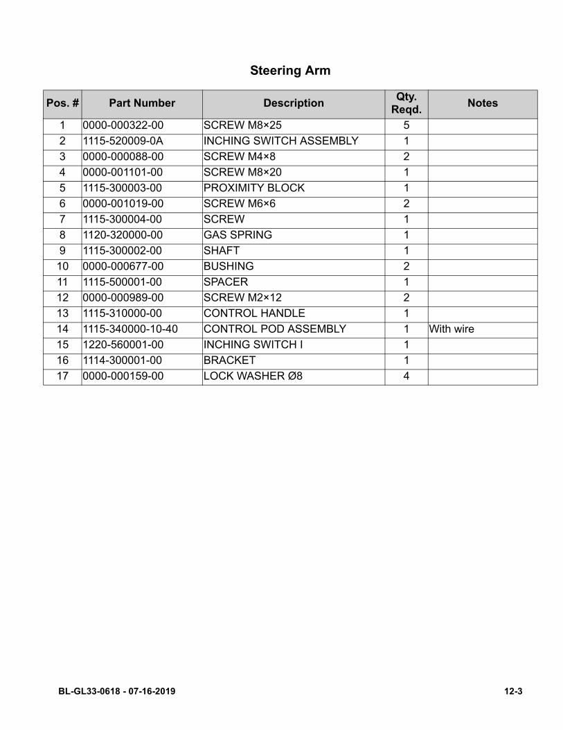
P
Steering Arm
os. # Part Number DescriptionQty.
Reqd.Notes
1 0000-000322-00 SCREW M8×25 5
2 1115-520009-0A INCHING SWITCH ASSEMBLY 1
3 0000-000088-00 SCREW M4×8 2
4 0000-001101-00 SCREW M8×20 1
5 1115-300003-00 PROXIMITY BLOCK 1
6 0000-001019-00 SCREW M6×6 2
7 1115-300004-00 SCREW 1
8 1120-320000-00 GAS SPRING 1
9 1115-300002-00 SHAFT 1
10 0000-000677-00 BUSHING 2
11 1115-500001-00 SPACER 1
12 0000-000989-00 SCREW M2×12 2
13 1115-310000-00 CONTROL HANDLE 1
14 1115-340000-10-40 CONTROL POD ASSEMBLY 1 With wire
15 1220-560001-00 INCHING SWITCH I 1
16 1114-300001-00 BRACKET 1
17 0000-000159-00 LOCK WASHER Ø8 4
BL-GL33-0618 - 07-16-2019 12-3

Figure 12-2 Control Head
GL33-3
12-4 BL-GL33-0618 - 07-16-2019
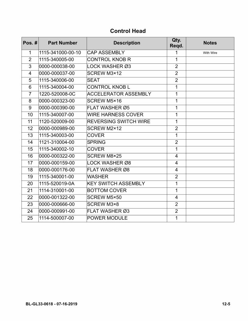
Control Head
Pos. # Part Number DescriptionQty.
Reqd.Notes
1 1115-341000-00-10 CAP ASSEMBLY 1 With Wire
2 1115-340005-00 CONTROL KNOB R 1
3 0000-000038-00 LOCK WASHER Ø3 2
4 0000-000037-00 SCREW M3×12 2
5 1115-340006-00 SEAT 2
6 1115-340004-00 CONTROL KNOB L 1
7 1220-520008-0C ACCELERATOR ASSEMBLY 1
8 0000-000323-00 SCREW M5×16 1
9 0000-000390-00 FLAT WASHER Ø5 1
10 1115-340007-00 WIRE HARNESS COVER 1
11 1120-520009-00 REVERSING SWITCH WIRE 1
12 0000-000989-00 SCREW M2×12 2
13 1115-340003-00 COVER 1
14 1121-310004-00 SPRING 2
15 1115-340002-10 COVER 1
16 0000-000322-00 SCREW M8×25 4
17 0000-000159-00 LOCK WASHER Ø8 4
18 0000-000176-00 FLAT WASHER Ø8 4
19 1115-340001-00 WASHER 2
20 1115-520019-0A KEY SWITCH ASSEMBLY 1
21 1114-310001-00 BOTTOM COVER 1
22 0000-001322-00 SCREW M5×50 4
23 0000-000666-00 SCREW M3×8 2
24 0000-000991-00 FLAT WASHER Ø3 2
25 1114-500007-00 POWER MODULE 1
BL-GL33-0618 - 07-16-2019 12-5
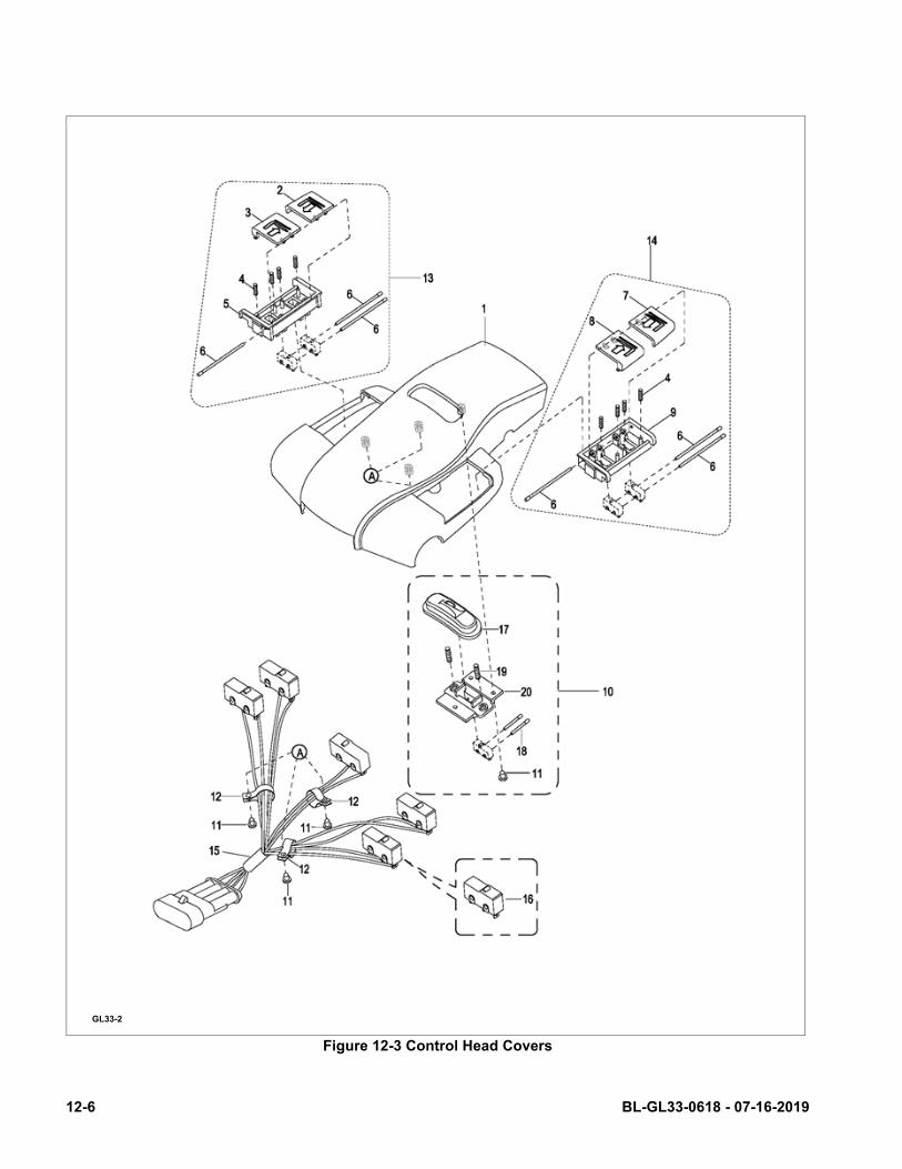
Figure 12-3 Control Head Covers
GL33-2
12-6 BL-GL33-0618 - 07-16-2019

Control Head Covers
Pos. # Part Number DescriptionQty.
Reqd.Notes
1 1115-341001-00 UPPER COVER 1
2 1120-342203-00 BUTTON FOR LIFTING (R) 1
3 1120-342202-00 BUTTON FOR LOWERING (R) 1
4 1120-342102-00 SPRING 8
5 1120-342201-00 BUTTON BRACKET (R) 1
6 1120-342105-00 PIN 6
7 1120-342104-00 BUTTON FOR LIFTING (L) 1
8 1120-342103-00 BUTTON FOR LOWERING (L) 1
9 1120-342101-00 BUTTON BRACKET (L) 1
10 1120-342300-00 HORN BUTTON ASSEMBLY 1
11 0000-000039-00 SCREW ST3.5×9.5 6
12 0000-000490-00 HARNESS CLAMP 3
13 1120-342200-00 LIFT AND LOWER BOX (R) ASSY. 1
14 1120-342100-00 LIFT AND LOWER BOX (L) ASSY. 1
15 1220-520006-0C HARNESS ASSEMBLY 1 With Switches16 1220-560002-00 SWITCH II 5
17 1120-342002-00 HORN BUTTON 1
18 1120-342005-00 PIN 2
19 1120-342003-00 SPRING 2
20 1120-342004-00 BUTTON BRACKET 1
BL-GL33-0618 - 07-16-2019 12-7
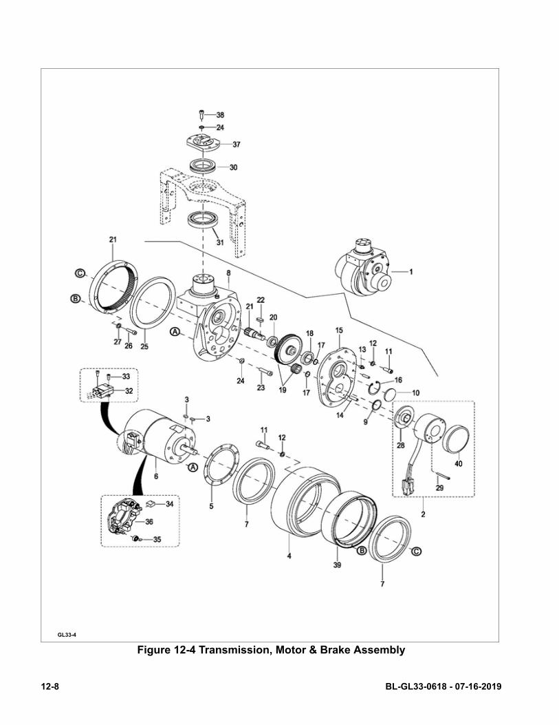
Figure 12-4 Transmission, Motor & Brake Assembly
GL33-4
12-8 BL-GL33-0618 - 07-16-2019

P
Transmission, Motor & Brake Assembly
os. # Part Number DescriptionQty.
Reqd.Notes
1 1121-200000-A0 DRIVING ASSEMBLY 1 Used up to Serial # 427202925, (Incl. Pos. # 2—27)
1a 1121-200000-03 DRIVING ASSEMBLY 1 Used from Serial # 427202926, (Incl. Pos. # 2—27)
2 1115-520012-0A BRAKE ASSEMBLY 1 Used up to Serial # 4271908262a 1115-520012-10 BRAKE ASSEMBLY 1 Used from Serial # 4271908273 0000-000662-00 FLAT KEY 5×5×12 2
4 1115-220000-A0 DRIVING WHEEL 1
5 1115-200010-00 BEARING BAFFLE 1
6 1115-250000-00 MOTOR 1
7 0000-000663-00 BEARING 2
8 1121-210001-00 GEAR CASE 1 Used up to Serial # 4272029258a 1121-210001-0E GEAR CASE 1 Used from Serial # 4272029269 0000-000671-00 OIL SEAL Ø16×28×7 1
10 1115-200007-00 CAP 1
11 0000-000386-00 SCREW M6×20 14
12 0000-000056-00 LOCK WASHER Ø6 14
13 0000-000013-00 GREASE FITTING M8 1
14 0000-000704-00 PIN Ø6×20 2
15 1115-200001-00 GEAR COVER 1
16 0000-000658-00 SNAP RING FOR HOLE Ø42 1
17 0000-000659-00 SNAP RING Ø15 2
18 0000-000667-00 BEARING 1
19 1115-GSX-10 GEAR KIT 1Used up to Serial # 427202925 - The kit includes 2 gears (Pos.19)
19a 1121-GB03-00 GEAR KIT 1Used from Serial # 427202926 -The kit includes 2 gears (Pos.19)
20 0000-000680-00 BEARING 1 Used up to Serial # 42720292520a 3090-010000-42 BEARING 1 Used from Serial # 427202926
BL-GL33-0618 - 07-16-2019 12-9
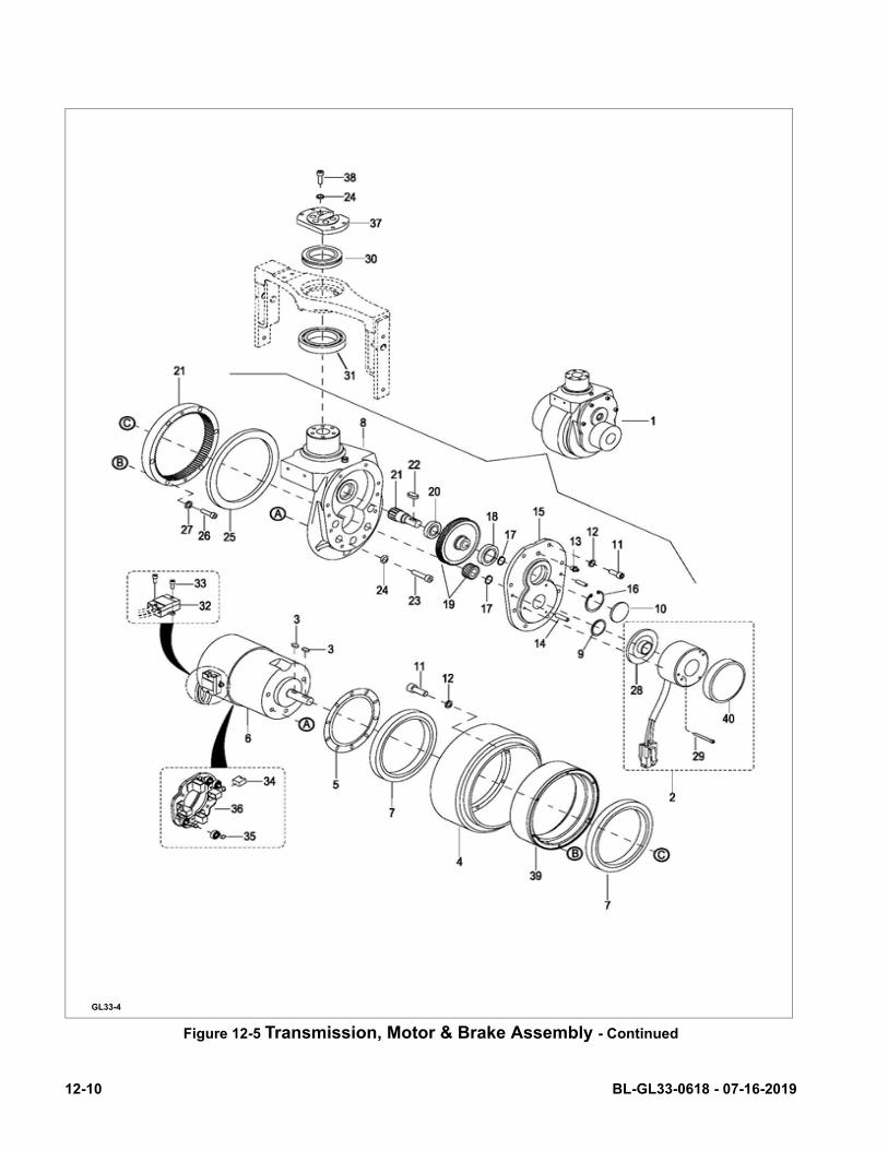
Figure 12-5 Transmission, Motor & Brake Assembly - Continued
GL33-4
12-10 BL-GL33-0618 - 07-16-2019
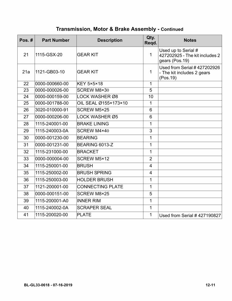
P
Transmission, Motor & Brake Assembly - Continued
os. # Part Number DescriptionQty.
Reqd.Notes
21 1115-GSX-20 GEAR KIT 1Used up to Serial # 427202925 - The kit includes 2gears (Pos.19)
21a 1121-GB03-10 GEAR KIT 1Used from Serial # 427202926- The kit includes 2 gears (Pos.19)
22 0000-000660-00 KEY 5×5×18 1
23 0000-000026-00 SCREW M8×30 5
24 0000-000159-00 LOCK WASHER Ø8 10
25 0000-001788-00 OIL SEAL Ø155×173×10 1
26 3020-010000-91 SCREW M5×25 6
27 0000-000206-00 LOCK WASHER Ø5 6
28 1115-240001-00 BRAKE LINING 1
29 1115-240003-0A SCREW M4×40 3
30 0000-001230-00 BEARING 1
31 0000-001231-00 BEARING 6013-Z 1
32 1115-231000-00 BRACKET 1
33 0000-000004-00 SCREW M5×12 2
34 1115-250001-00 BRUSH 4
35 1115-250002-00 BRUSH SPRING 4
36 1115-250003-00 HOLDER BRUSH 1
37 1121-200001-00 CONNECTING PLATE 1
38 0000-000151-00 SCREW M8×25 5
39 1115-200001-A0 INNER RIM 1
40 1115-240002-0A SCRAPER SEAL 1
41 1115-200020-00 PLATE 1 Used from Serial # 427190827
BL-GL33-0618 - 07-16-2019 12-11
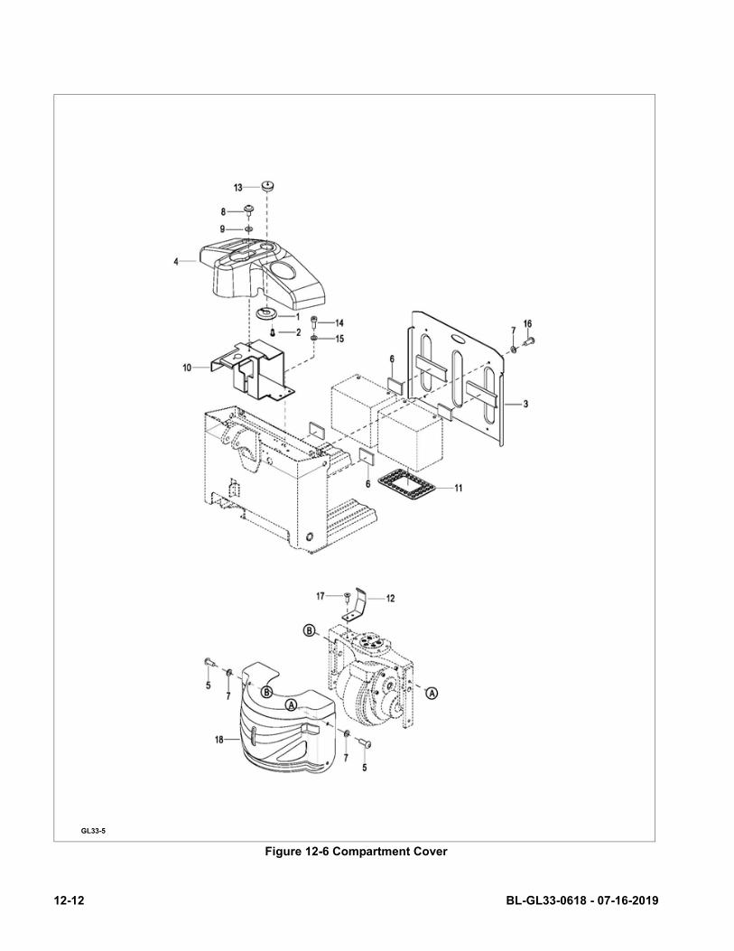
Figure 12-6 Compartment Cover
GL33-5
12-12 BL-GL33-0618 - 07-16-2019
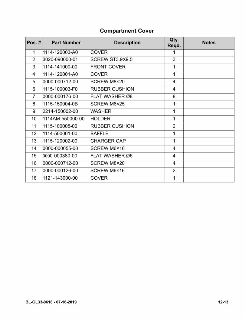
Compartment Cover
Pos. # Part Number DescriptionQty.
Reqd.Notes
1 1114-120003-A0 COVER 1
2 3020-090000-01 SCREW ST3.9X9.5 3
3 1114-141000-00 FRONT COVER 1
4 1114-120001-A0 COVER 1
5 0000-000712-00 SCREW M8×20 4
6 1115-100003-F0 RUBBER CUSHION 4
7 0000-000176-00 FLAT WASHER Ø8 8
8 1115-150004-0B SCREW M6×25 1
9 2214-150002-00 WASHER 1
10 1114AM-550000-00 HOLDER 1
11 1115-100005-00 RUBBER CUSHION 2
12 1114-500001-00 BAFFLE 1
13 1115-120002-00 CHARGER CAP 1
14 0000-000055-00 SCREW M6×16 4
15 0000-000380-00 FLAT WASHER Ø6 4
16 0000-000712-00 SCREW M8×20 4
17 0000-000126-00 SCREW M6×16 2
18 1121-143000-00 COVER 1
BL-GL33-0618 - 07-16-2019 12-13

Figure 12-7 Frame
GL33-6
12-14 BL-GL33-0618 - 07-16-2019

Po
Frame
s. # Part Number DescriptionQty.
Reqd.Notes
1 1114AP-110000-0A-01-GL FRONT FRAME 1 Width over forks 27” Fork Length 45”
2 1121-120000-00 BACK FRAME 1
3 0000-001456-00 ROUND PIN Ø5×35 4
4 1114-130001-10 LONG SHAFT 1
5 1121-130002-00 SHORT SHAFT 2
6 1114-130002-00 SHAFT 2
7 0000-000088-00 SCREW M4×8 2
8 1115-500002-00 HARNESS CLAMP 1
9 0000-000410-00 ROUND PIN Ø6×40 1
BL-GL33-0618 - 07-16-2019 12-15
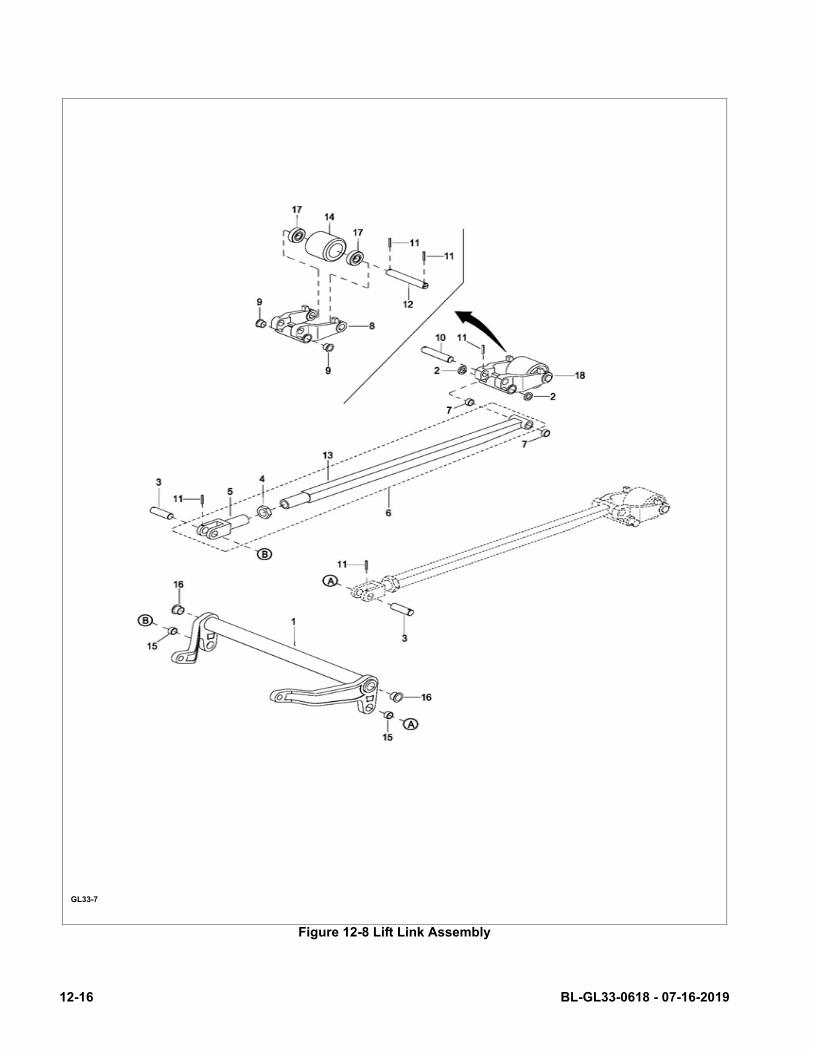
Figure 12-8 Lift Link Assembly
GL33-7
12-16 BL-GL33-0618 - 07-16-2019
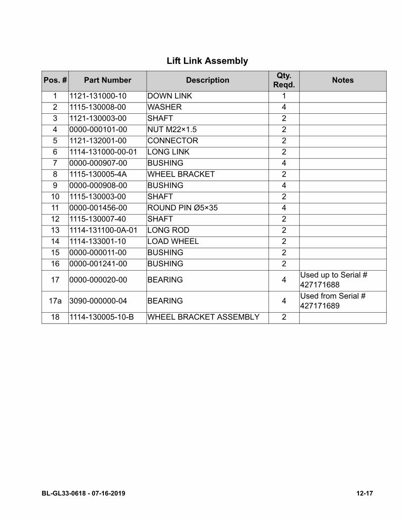
Lift Link Assembly
Pos. # Part Number DescriptionQty.
Reqd.Notes
1 1121-131000-10 DOWN LINK 1
2 1115-130008-00 WASHER 4
3 1121-130003-00 SHAFT 2
4 0000-000101-00 NUT M22×1.5 2
5 1121-132001-00 CONNECTOR 2
6 1114-131000-00-01 LONG LINK 2
7 0000-000907-00 BUSHING 4
8 1115-130005-4A WHEEL BRACKET 2
9 0000-000908-00 BUSHING 4
10 1115-130003-00 SHAFT 2
11 0000-001456-00 ROUND PIN Ø5×35 4
12 1115-130007-40 SHAFT 2
13 1114-131100-0A-01 LONG ROD 2
14 1114-133001-10 LOAD WHEEL 2
15 0000-000011-00 BUSHING 2
16 0000-001241-00 BUSHING 2
17 0000-000020-00 BEARING 4Used up to Serial # 427171688
17a 3090-000000-04 BEARING 4Used from Serial # 427171689
18 1114-130005-10-B WHEEL BRACKET ASSEMBLY 2
BL-GL33-0618 - 07-16-2019 12-17
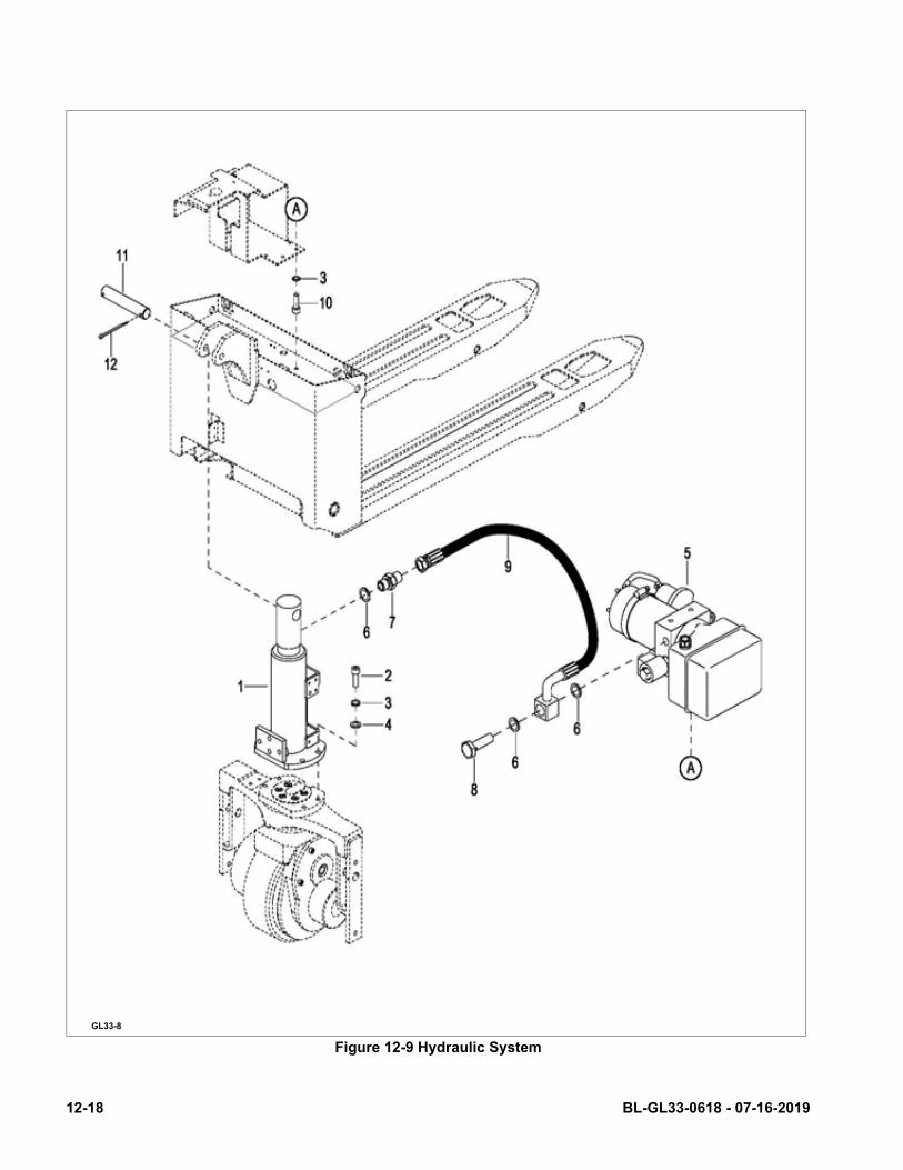
Figure 12-9 Hydraulic System
GL33-8
12-18 BL-GL33-0618 - 07-16-2019
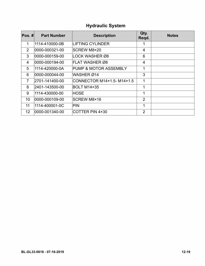
Hydraulic System
Pos. # Part Number DescriptionQty.
Reqd.Notes
1 1114-410000-0B LIFTING CYLINDER 1
2 0000-000321-00 SCREW M8×20 4
3 0000-000159-00 LOCK WASHER Ø8 6
4 0000-000194-00 FLAT WASHER Ø8 4
5 1114-420000-0A PUMP & MOTOR ASSEMBLY 1
6 0000-000044-00 WASHER Ø14 3
7 2701-141400-00 CONNECTOR M14×1.5- M14×1.5 1
8 2401-143500-00 BOLT M14×35 1
9 1114-430000-00 HOSE 1
10 0000-000109-00 SCREW M8×16 2
11 1114-400001-0C PIN 1
12 0000-001340-00 COTTER PIN 4×30 2
BL-GL33-0618 - 07-16-2019 12-19
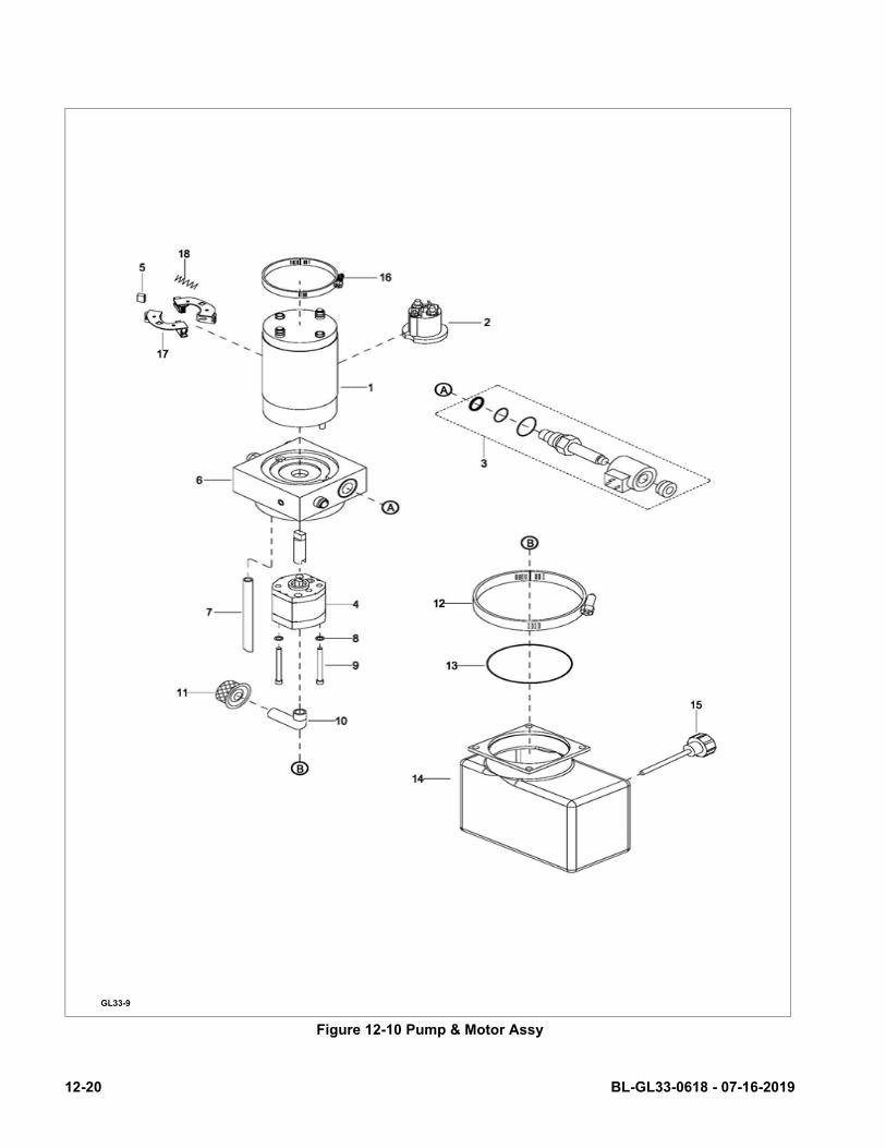
Figure 12-10 Pump & Motor Assy
GL33-9
12-20 BL-GL33-0618 - 07-16-2019
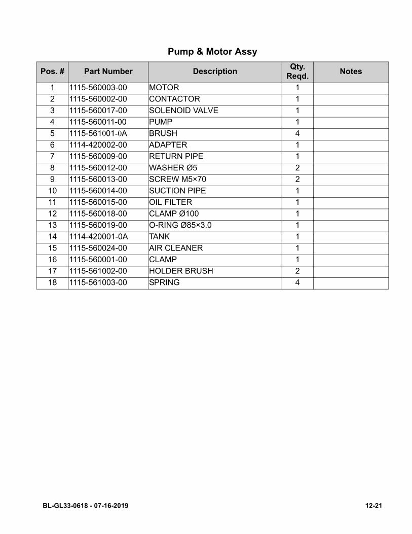
Pump & Motor Assy
Pos. # Part Number DescriptionQty.
Reqd.Notes
1 1115-560003-00 MOTOR 1
2 1115-560002-00 CONTACTOR 1
3 1115-560017-00 SOLENOID VALVE 1
4 1115-560011-00 PUMP 1
5 1115-561001-0A BRUSH 4
6 1114-420002-00 ADAPTER 1
7 1115-560009-00 RETURN PIPE 1
8 1115-560012-00 WASHER Ø5 2
9 1115-560013-00 SCREW M5×70 2
10 1115-560014-00 SUCTION PIPE 1
11 1115-560015-00 OIL FILTER 1
12 1115-560018-00 CLAMP Ø100 1
13 1115-560019-00 O-RING Ø85×3.0 1
14 1114-420001-0A TANK 1
15 1115-560024-00 AIR CLEANER 1
16 1115-560001-00 CLAMP 1
17 1115-561002-00 HOLDER BRUSH 2
18 1115-561003-00 SPRING 4
BL-GL33-0618 - 07-16-2019 12-21

GL33-10
12-22 BL-GL33-0618 - 07-16-2019
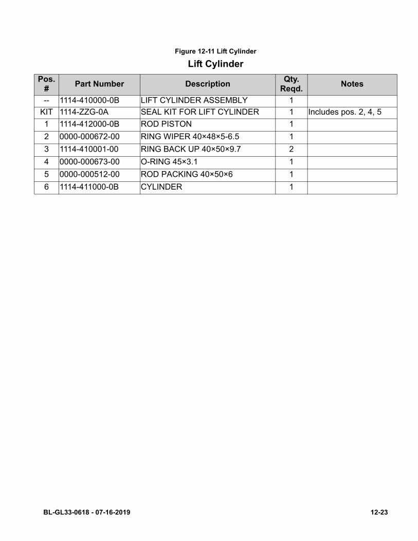
Figure 12-11 Lift Cylinder
Lift Cylinder
Pos. #
Part Number DescriptionQty.
Reqd.Notes
-- 1114-410000-0B LIFT CYLINDER ASSEMBLY 1
KIT 1114-ZZG-0A SEAL KIT FOR LIFT CYLINDER 1 Includes pos. 2, 4, 5
1 1114-412000-0B ROD PISTON 1
2 0000-000672-00 RING WIPER 40×48×5-6.5 1
3 1114-410001-00 RING BACK UP 40×50×9.7 2
4 0000-000673-00 O-RING 45×3.1 1
5 0000-000512-00 ROD PACKING 40×50×6 1
6 1114-411000-0B CYLINDER 1
BL-GL33-0618 - 07-16-2019 12-23
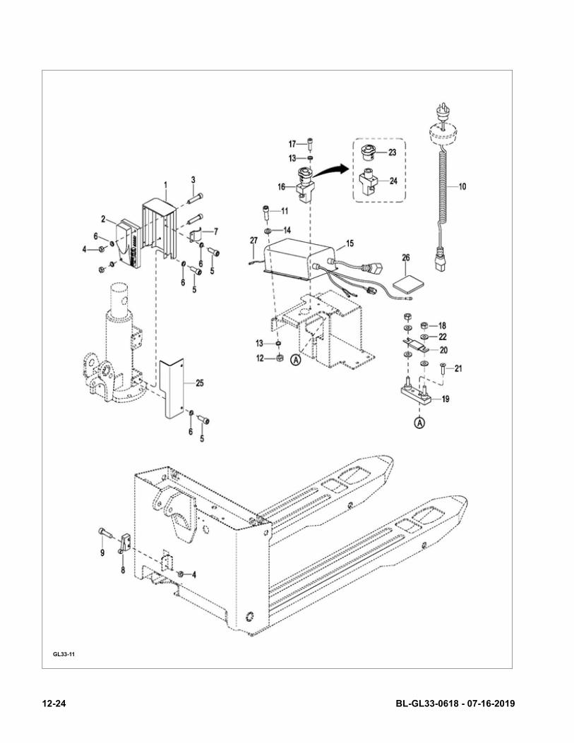
GL33-11
12-24 BL-GL33-0618 - 07-16-2019
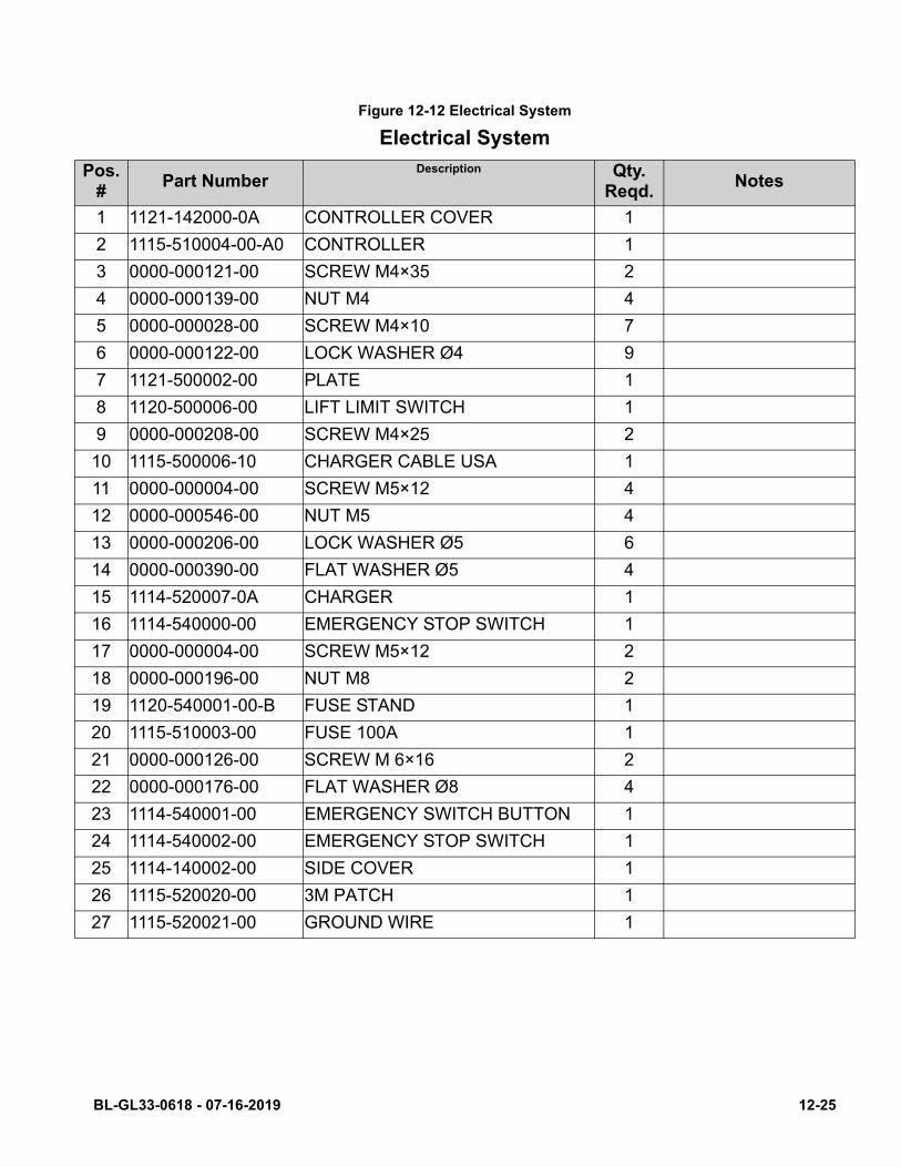
Figure 12-12 Electrical System
Electrical System
Pos. #
Part NumberDescription Qty.
Reqd.Notes
1 1121-142000-0A CONTROLLER COVER 1
2 1115-510004-00-A0 CONTROLLER 1
3 0000-000121-00 SCREW M4×35 2
4 0000-000139-00 NUT M4 4
5 0000-000028-00 SCREW M4×10 7
6 0000-000122-00 LOCK WASHER Ø4 9
7 1121-500002-00 PLATE 1
8 1120-500006-00 LIFT LIMIT SWITCH 1
9 0000-000208-00 SCREW M4×25 2
10 1115-500006-10 CHARGER CABLE USA 1
11 0000-000004-00 SCREW M5×12 4
12 0000-000546-00 NUT M5 4
13 0000-000206-00 LOCK WASHER Ø5 6
14 0000-000390-00 FLAT WASHER Ø5 4
15 1114-520007-0A CHARGER 1
16 1114-540000-00 EMERGENCY STOP SWITCH 1
17 0000-000004-00 SCREW M5×12 2
18 0000-000196-00 NUT M8 2
19 1120-540001-00-B FUSE STAND 1
20 1115-510003-00 FUSE 100A 1
21 0000-000126-00 SCREW M 6×16 2
22 0000-000176-00 FLAT WASHER Ø8 4
23 1114-540001-00 EMERGENCY SWITCH BUTTON 1
24 1114-540002-00 EMERGENCY STOP SWITCH 1
25 1114-140002-00 SIDE COVER 1
26 1115-520020-00 3M PATCH 1
27 1115-520021-00 GROUND WIRE 1
BL-GL33-0618 - 07-16-2019 12-25
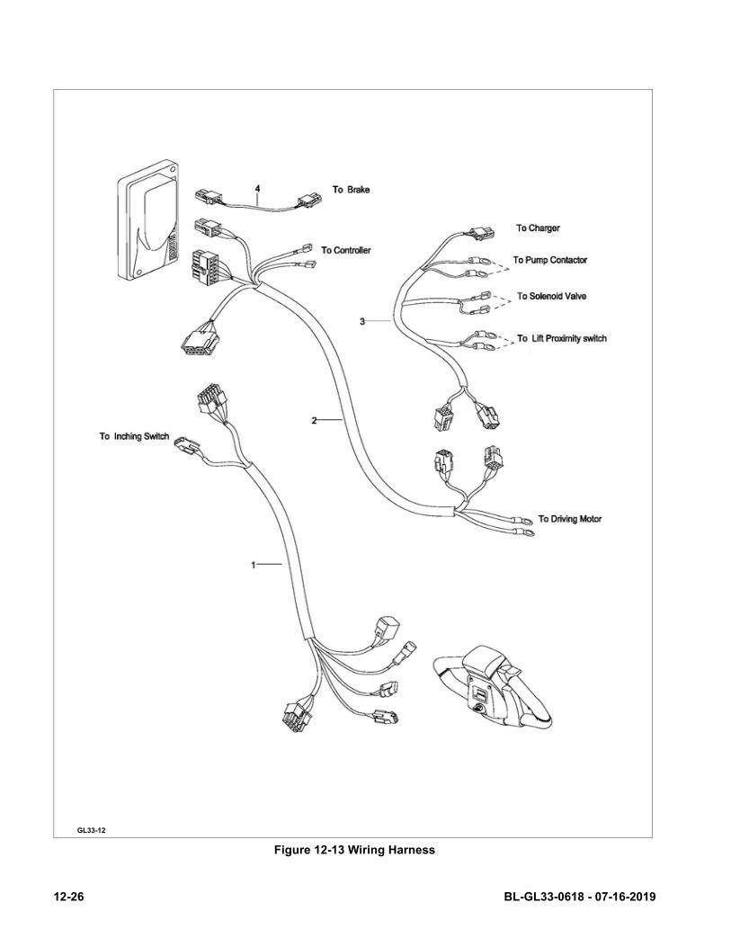
Figure 12-13 Wiring Harness
GL33-12
12-26 BL-GL33-0618 - 07-16-2019
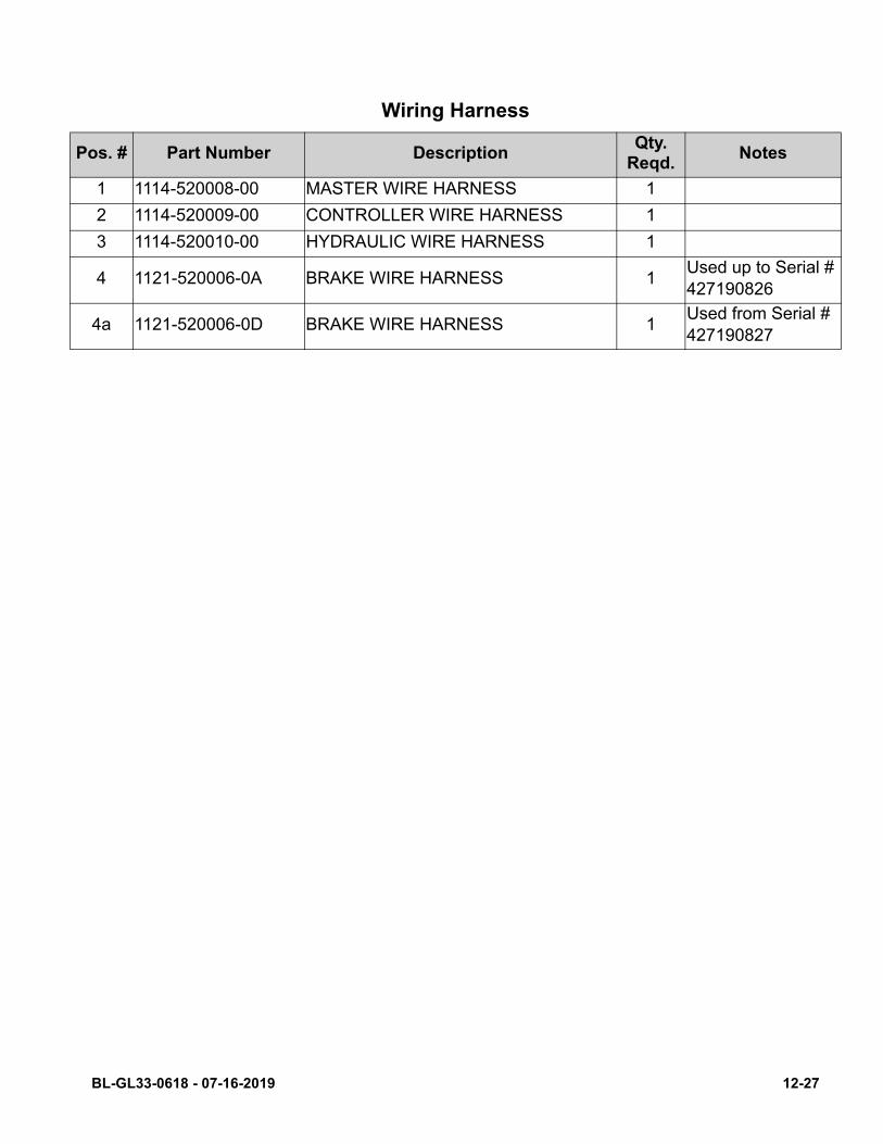
P
Wiring Harness
os. # Part Number DescriptionQty.
Reqd.Notes
1 1114-520008-00 MASTER WIRE HARNESS 1
2 1114-520009-00 CONTROLLER WIRE HARNESS 1
3 1114-520010-00 HYDRAULIC WIRE HARNESS 1
4 1121-520006-0A BRAKE WIRE HARNESS 1Used up to Serial #427190826
4a 1121-520006-0D BRAKE WIRE HARNESS 1Used from Serial # 427190827
BL-GL33-0618 - 07-16-2019 12-27
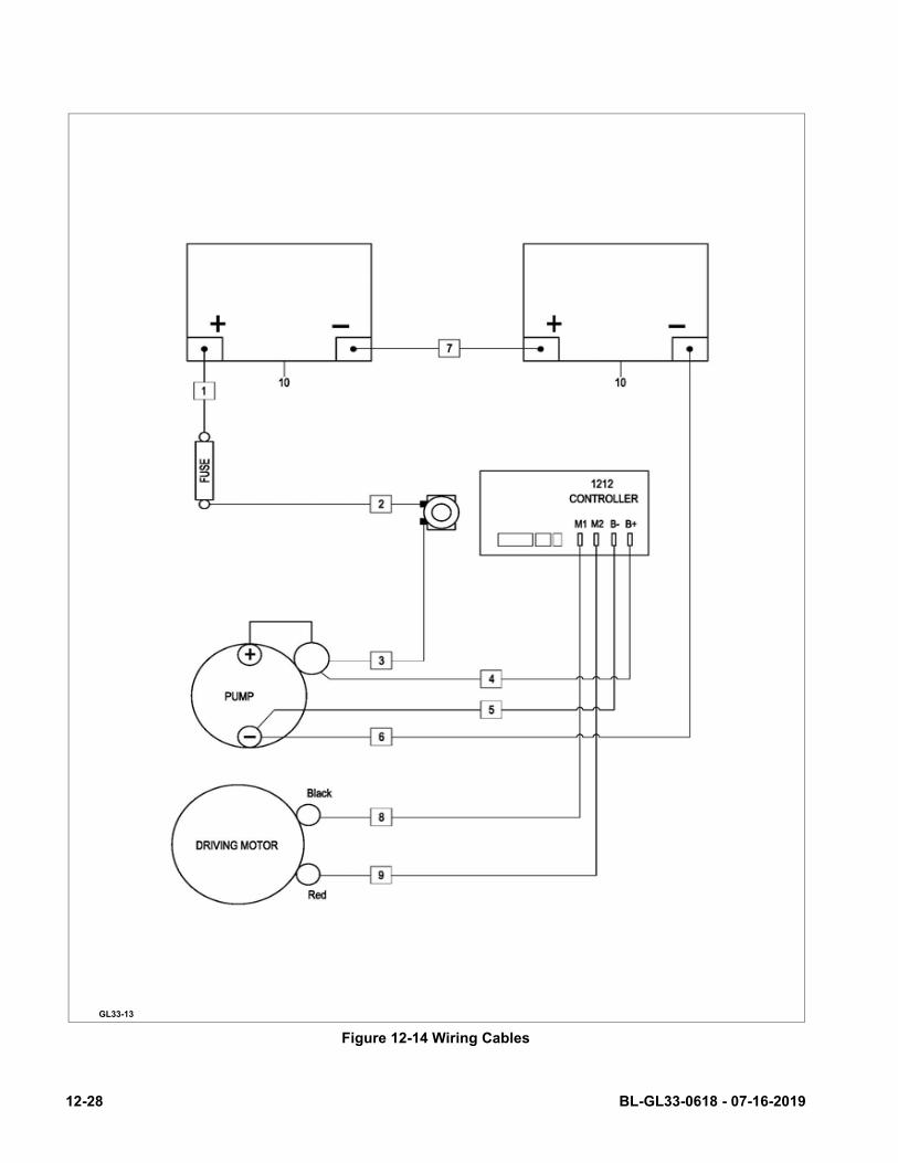
Figure 12-14 Wiring Cables
GL33-13
12-28 BL-GL33-0618 - 07-16-2019
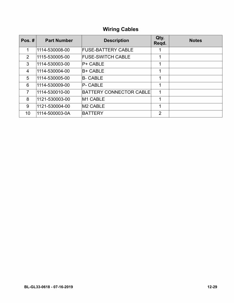
Wiring Cables
Pos. # Part Number DescriptionQty.
Reqd.Notes
1 1114-530008-00 FUSE-BATTERY CABLE 1
2 1115-530005-00 FUSE-SWITCH CABLE 1
3 1114-530003-00 P+ CABLE 1
4 1114-530004-00 B+ CABLE 1
5 1114-530005-00 B- CABLE 1
6 1114-530009-00 P- CABLE 1
7 1114-530010-00 BATTERY CONNECTOR CABLE 1
8 1121-530003-00 M1 CABLE 1
9 1121-530004-00 M2 CABLE 1
10 1114-500003-0A BATTERY 2
BL-GL33-0618 - 07-16-2019 12-29