Embed Size (px)
Citation preview

CONVERTING NON POSI REAR END TO POSI ‘55 – ‘64 Chevrolet passenger car and ’56 – ’62 Corvette
By Tom Parsons
This article will be specifically directed at converting the 55-64 Chevrolet full size pass car and 56-62 Corvette NON-positraction rear end to
positraction using an Eaton aftermarket posi unit. But, much of the information will be applicable to the original factory positraction units
(originally made for GM by DANA).
I am not going to include detailed assembly and setup procedures in this article. Here is a link to the factory 56 Chevrolet rearend rebuilding procedures which is applicable for 55-64 rearends and is very complete. This manual can be down loaded and printed if you wish to add it to
your library.
http://chevy.oldcarmanualproject.com/booklets/5603top00.htm
There were primarily 2 different rearend center cases between 55 and 64 along with multiple casting numbers, but the two primary
differences were the 55-56 case and the 57-64 case. To convert the 55-56 rear to posi, it is a VERY straight forward process of installing the
ring gear on the posi unit, installing the posi with ring gear in the case, set the bearing preload and backlash. THERE IS NO NEED TO REMOVE
THE PINION GEAR to convert a 55-56 rear to posi. Also, depending on the ring gear used with a posi unit in a 55-56 case (ESPECIALLY if the ring gear is an original 55-6 ring gear), it MAY be necessary to use a ring gear spacer. The reason is because original 55-56 ring gears are
thinner than 57-64 ring gears. Ring gear spacers are readily available from the aftermarket sources. Also, for added information, the 55-56
case is not as beefy, thus, not quite as strong as the 57-64 case.
The conversion that was done in this article is on a 57 center section which eventually is going into a customer’s 52 Chevy with a 57
passenger car axle housing.
Here is a 55-56 style case with a posi already installed.

This is a 57-64 style NON-posi rear before disassembly. As can be clearly seen, the 57-64 case has a thicker, stronger webbing for the carrier
bearings.

This is the non-posi case after disassembly and before cleaning. Notice the +1 which was hand painted on the assembly line during the
original factory assembly process. This +1 marking is related to shim thickness installation on the pinion gear.
Also notice there are two protrusions that are cast inside the case. The squared off one is in all cases, both posi and non-posi. The angled protrusion, or gusset, is ONLY in the 57-64 NON-posi cases.
THIS IS WHERE A MODIFICATION IS REQUIRED FOR THE 57-64 NON-POSI CASE BEFORE A POSI UNIT CAN BE INSTALLED. A portion of this
gusset must be removed to provide clearance for the posi unit, and it does not matter if an original factory style posi is used or an
aftermarket posi unit such as the Eaton is used.

I use a die grinder and a thin cutoff disc to remove the major portion of the gusset. The gusset only needs to be cut off about 1 1/2in from
the mating surface for the bearing cap. It is important to remove the portion of the gusset ALL THE WAY to the inner wall of the case.
Here is the case after the portion of the gusset is removed. After cutting the larger portion of the gusset with a cutoff disc, I use a rotary file in the die grinder to remove the remainder of the gusset, then a small sanding disc to smooth out the grinding marks. I also smoothed out
the parting lines from the casting mold.

The next step is blasting the case inside and out. I concentrate blasting on the areas where the grinding was done just to make an even finish
all over. This step is not necessary, but this is how I do it.


Once the case is cleaned and blasted, it is much easier to read the casting numbers and casting date on the driver side of the case and the ratio code and assembly date (AB 523-May 23) on the passenger side.

Often the stamped code and assembly date seen below is VERY difficult to find and usually requires thoroughly cleaning down to the bare cast iron.

Painting is optional and your choice. Many early cases were painted a red oxide inside and outside, similar to that below. As can be seen, I hand brushed green paint to attempt to duplicate the original marking from the factory. This step is totally unnecessary
because it will never be seen after installation in the axle housing, but some people like it. No extra charge!

As can also be seen, once painted on the outside, the numbers and codes are not quite as easy to distinguish.


Here are all the parts to go into this case. The customer wanted a brand new ring and pinion gear set. I wish to mention that if an original Chevy ring and pinion gear set in good
condition is available, use it! The original Chevy gears are excellent quality and there is no reason to not re-use them. This is also the new
Eaton posi unit, all new bearings, crush sleeve and pinion seal.
The first thing is to drive in the new pinion races. I have taken a pair (front/rear) of old races and slightly ground down the outer diameter so that they just slip into the holes in the case. I use the old races to do final driving of the new races to the bottom of their respective holes.
Since the gears are new, even though the new pinion is marked for pinion depth, I have quit trying to set the depth. I start out selecting a
pinion shim of .030in, slip it on and then press on the pinion bearing.

Lightly lube the pinion bearings and slip the pinion into the case, slip on the crush sleeve------------------ NO PINION SEAL YET--------------then the front pinion bearing, the yoke, big washer and pinion nut. Depending on condition of the old pinion nut, you may or may not choose
to re-use it. For an original pinion nut that has never been removed, I frequently re-use it (I’ll get a lot of flak over this!).

Years ago, I made my own pinion yoke holding tool from a piece of 1/2in steel plate. I cut it to shape with my die grinder and cutoff disc,
drilled the holes and drilled for holes for each corner of the square hole to fit a 3/4in drive breaker bar into. I also drilled two holes for attachment of a very long handle which I made from a piece of steel rod.


Now bolt the ring gear onto the posi unit and drive the new carrier bearings onto the posi unit. Place the bearing races on the bearings and
set the entire assembly into the case. I’m not going into detail here because all of the information for assembly is in the 56 Chevy rearend
manual located at the link at the beginning of this article.
You can see from the next two pictures where the removed portion of the gusset has provided plenty of clearance for the posi unit.

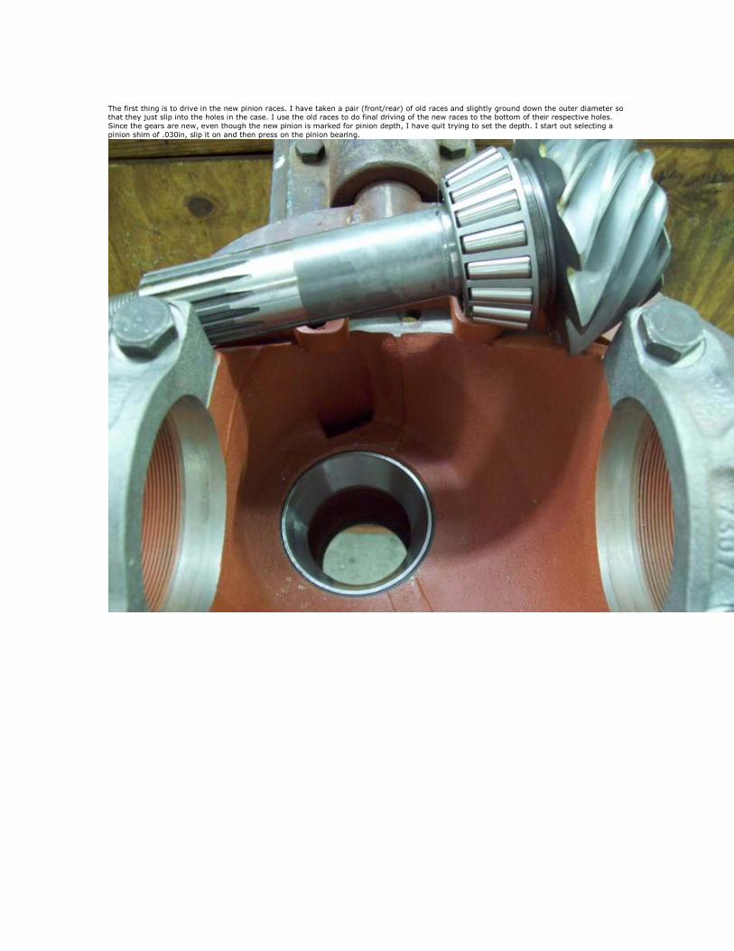
Also, notice the two punch marks on the case and the cap. I do this (failed to mention it much earlier) prior to disassembly so that there is no confusion which cap goes on which side. I make one punch mark on one side, two punch marks on the other side.

Again, the 56 rearend manual is quite clear about how to set bearing preload and backlash.
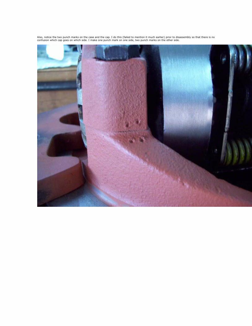
Here is my dial indicator showing .005in backlash in two different locations. The ideal range is .005-.008.


Once the backlash and carrier bearing preload is established, I check the tooth contact pattern with white marking compound brushed on
BOTH sides of 4-5 teeth.
Also, the 56 rearend manual is quite clear about how to apply pressure on the gears to obtain a pattern.
This pattern was ultimately achieved with a .031 pinion shim. This is NOT the most perfect pattern, but it was the most optimal I could achieve and the MOST desirable pattern is on the DRIVE side of the teeth, which is what I ended up with here. By changing to a thinner shim,
to get the drive side pattern deeper, it makes toe coast pattern go further than desirable in the opposite direction. So, this is what I got.
UNDERSTAND, YOU MAY NOT ALWAYS GET A PATTERN AS SHOWN IN THE ILLUSTRATIONS OF CONTACT PATTERNS. Thus, you just have to
go with the BEST pattern that can be achieved. Also, with USED gears, this is the ONLY way to get an optimal pattern. Of course, this may (and probably will) require tearing down the rear 2-3-4-5 times, pressing off and on the pinion bearing to change shims until you end up with
an acceptable pattern.


Once all adjustments and setup is complete, remove the nut, washer and yoke and install the new pinion seal. I like to use a VERY light coating of gasket sealer around the seal before carefully tapping it into the case.

Before putting the yoke back on, I THOROUGHLY clean the splines of the pinion and yoke and paint gasket sealer in the splines of the yoke to
seal against an oil leaking through the splines. Put the yoke back on, then the washer and nut.


When I first setup the pinion with the new crush sleeve, BEFORE installing the new seal, I only tighten the nut to achieve about 20in/lb
preload on the pinion bearings. Once the seal is installed and the yoke, washer and nut is finally installed, I also use gasket sealer on the
washer and nut, then finish tightening the pinion nut to achieve the 25in/lbs specified in the rearend manual.


Finally finished.

Tom Parsons