Embed Size (px)
Citation preview
Model 6515A Operating Instructions
MODEL 6515A LEAK TESTER
OPERATING INSTRUCTIONS
for version 1.57 & later
27 December, 1999
COPYRIGHT (C) 1995, 2000 S. HIMMELSTEIN & CO.
2490 PEMBROKE AVE. HOFFMAN ESTATES, IL 60195

Model 6515A Operating Instructions
Model 6515A Operating Instructions
SECTION ................................................................. PAGE
1. Introduction ...................................................................1
2. Description ................................................................... 32.1 Operator Controls ..................................................32.2 Indicators ...............................................................32.3 Channel Assignments............................................42.4 Keypad...................................................................42.5 Numeric and Alphanumeric Displays .....................82.6 Amplifier Adjustment Controls ...............................8
3. Installation ...................................................................113.1 Setup and Connection .........................................113.2 Power-on .............................................................13
4. Operation .....................................................................154.1 Operating Modes .................................................154.2 Entering Test Parameters....................................154.3 Setting the Pressure Switch.................................194.4 Running a Leak Test............................................194.5 Calibration Check.................................................204.6 Printouts...............................................................204.7 Remote I/O with Host Computer
or Terminal .........................................................234.8 TIME and LEGEND Keys ....................................26
5. Communications Interfaces.......................................295.1 Printer Port...........................................................295.2 ASCII Input/Output...............................................295.3 General Purpose Instrument Bus ........................30
6. Specifications and Electrical Loads..........................31
7. Error Messages ...........................................................33
8. Theory of Operation....................................................37
9. Calibration Procedure ................................................41
10. Advanced Options ......................................................45
Appendix I - Determining Leak Units Constants.................47
Appendix II - List of Leak Test Parameters ........................48
TABLEOF CONTENTS

Model 6515A Operating Instructions
Model 6515A Operating Instructions
Page 1
The Model 6515A Fully Automatic Leak Tester employs thepressure (or vacuum) decay Leak test principle, to provide fast,accurate, and repeatable determination of test unit leakage.Once started, the Leak Tester goes through the entire Leaktest, including Fill (or Evacuate), Stabilize, and Test (measurethe pressure decay) phases without external intervention. Whenfinished, it signals OK or FAIL, and displays the calculated leakrate in units of your choice. When it detects a Gross Leaker, itterminates the test and signals GROSS (and FAIL).
If the Leak Tester was purchased with the 10 Selector option,parameters for up to 10 different tests may be stored in theLeak Tester memory. The appropriate parameter set isselected by keypad push-buttons or external Logic Level inputs.
The Model 6515 Leak Tester consists of separate electronicand pneumatic enclosures.
● The electronic enclosure houses the displays, keypad,processor, valve drivers, communication interfaces, andoperator controls.
● The pneumatic enclosure contains thesolenoid-controlled valves, pressure (vacuum) switchdifferential pressure transducer, inlet pressure regulator,and pressure (vacuum) gauge.
See Figure 1 for interconnect details of hoses and cables.
INTRODUCTION 1

Model 6515A Operating Instructions
Page 2
Model 6515A Operating Instructions
Page 3
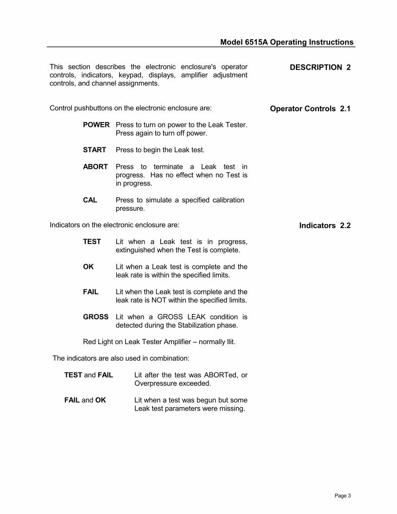
This section describes the electronic enclosure's operatorcontrols, indicators, keypad, displays, amplifier adjustmentcontrols, and channel assignments.
DESCRIPTION 2
Control pushbuttons on the electronic enclosure are:
POWER Press to turn on power to the Leak Tester.Press again to turn off power.
START Press to begin the Leak test.
ABORT Press to terminate a Leak test inprogress. Has no effect when no Test isin progress.
CAL Press to simulate a specified calibration pressure.
Operator Controls 2.1
Indicators on the electronic enclosure are:
TEST Lit when a Leak test is in progress,extinguished when the Test is complete.
OK Lit when a Leak test is complete and theleak rate is within the specified limits.
FAIL Lit when the Leak test is complete and theleak rate is NOT within the specified limits.
GROSS Lit when a GROSS LEAK condition isdetected during the Stabilization phase.
Red Light on Leak Tester Amplifier – normally llit.
The indicators are also used in combination:
TEST and FAIL Lit after the test was ABORTed, orOverpressure exceeded.
FAIL and OK Lit when a test was begun but someLeak test parameters were missing.
Indicators 2.2

Model 6515A Operating Instructions
Page 4
2.3 Channel Assignments The channels have default legends which may be changed with theRemote I/O 'LG' command, or from the keypad using the LGNDkey. The assignments and default legends are:
CH# Legend Channel Description 1 PSI Differential pressure 2 PSI DROP Pressure drop in Test phase 3 selectable Calculated Leak rate 4 RESERVED not used without 10 Selector option
or 4 SELECTOR# Selector number with 10 Selector option 5 OK PARTS # of acceptable parts 6 TOTAL # of parts tested 7 BAD PARTS # of measurable-leaker parts 8 GR LEAKS # of gross-leaker parts 9 TEST PSI User-entered Test Pressure10 % PASS Percentage of OK parts11 % FAIL Percentage of leaking parts12 MAX LEAK Maximum leak rate13 MIN LEAK Minimum leak rate14 SPREAD Difference between MAX and MIN
LEAK15 LOT SIZE Total of OK and BAD parts16 AVG LEAK Average calculated leak rate17 STD DEV Standard Deviation of leak rates
NOTE: Channel 3 legend is provided automatically according tothe Leak Units chosen.
2.4 Keypad The keypad is in a slide-out drawer in the electronic enclosure.The labels above or below the keys apply in Program mode,whereas the labels on the key apply in Operate mode. Keyswithout a label above or below have similar meanings in bothmodes.
- causes following digit(s) to be interpreted as thenew channel number.
- ends a keyboard sequence: for instance, to selectchannel 7, press the CHAN, 7, and ENTR keys.
ABC - number keys have 3 alphabetic characters above orbelow them; 1 character of the 3 is selected bypressing this key, another numeric key, and theALPH key.
- ten keys, marked "0" through "9", are used to enteralphanumeric information in both modes.
CHAN
ENTR
#
Model 6515A Operating Instructions
Page 5
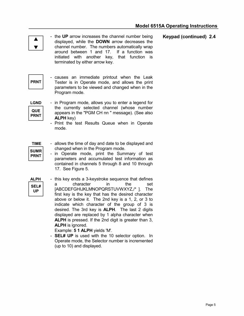
- the UP arrow increases the channel number beingdisplayed, while the DOWN arrow decreases thechannel number. The numbers automatically wraparound between 1 and 17. If a function wasinitiated with another key, that function isterminated by either arrow key.
- causes an immediate printout when the LeakTester is in Operate mode, and allows the printparameters to be viewed and changed when in theProgram mode.
LGND - in Program mode, allows you to enter a legend forthe currently selected channel (whose numberappears in the "PGM CH nn " message). (See alsoALPH key)
- Print the test Results Queue when in Operatemode.
TIME - allows the time of day and date to be displayed andchanged when in the Program mode.
- in Operate mode, print the Summary of testparameters and accumulated test information ascontained in channels 5 through 8 and 10 through17. See Figure 5.
ALPH - this key ends a 3-keystroke sequence that definesa character in the set[ABCDEFGHIJKLMNOPQRSTUVWXYZ,/* ]. Thefirst key is the key that has the desired characterabove or below it. The 2nd key is a 1, 2, or 3 toindicate which character of the group of 3 isdesired. The 3rd key is ALPH. The last 2 digitsdisplayed are replaced by 1 alpha character whenALPH is pressed. If the 2nd digit is greater than 3,ALPH is ignored.Example: 5 1 ALPH yields 'M'.
- SEL# UP is used with the 10 selector option. InOperate mode, the Selector number is incremented(up to 10) and displayed.
Keypad (continued) 2.4
SUMRPRNT
SEL#UP
QUEPRNT
PRNT
!"

Model 6515A Operating Instructions
Page 6
DEL
2.4 Keypad (continued) - SEL# DOWN is used with the 10 selector option.In Operate mode, the Selector number isdecremented (down to 1) and displayed.
. - enter a period or a decimal point in Programmode.
- selects the minus sign (with one press) or theplus sign with another keypress; in someprogramming sequences, it allows you toalternate between choices of parameters.
OPER - change from Program to Operate mode (afterENTR is pressed).
- change from Operate to Program mode (afterENTR is pressed). A 3-digit security code mustbe entered to get into Program mode. Thedefault code is 473, and if it is not enteredcorrectly in the first 3 tries, further tries are lockedout for 15 minutes. In Program mode the codecan be changed by pressing OPER, keying in 3digits, pressing ENTR to accept the new code.
- in Operate mode it resets the counters for LOTSIZE, OK, TOTAL, BAD, & GROSS LEAK parts,clears the % PASS, % FAIL, MAX LEAK, MINLEAK, SPREAD, AVG LEAK, and STD DEVchannels.
- in Program mode, this key is used to Deletenumbers, legends, or the printout header.
- this key displays the following parameters inOperate mode, and allows viewing and changingthem in Program mode:
FILL SEC.the number of seconds to pressurize (evacuate)the unit under test (UUT).
STABIL.SEC.the number of seconds for temperature settlingbefore the Test phase begins.
TEST SEC.the duration of the Test phase in seconds.
LEAKPARM
RSETCNTR
PGRM
SEL#DOWN
±±±±
Model 6515A Operating Instructions
Page 7
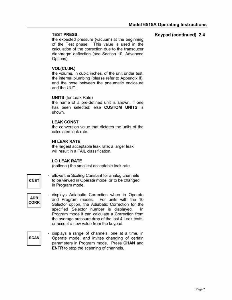
TEST PRESS.the expected pressure (vacuum) at the beginningof the Test phase. This value is used in thecalculation of the correction due to the transducerdiaphragm deflection (see Section 10, AdvancedOptions).
VOL(CU.IN.)the volume, in cubic inches, of the unit under test,the internal plumbing (please refer to Appendix II),and the hose between the pneumatic enclosureand the UUT.
UNITS (for Leak Rate)the name of a pre-defined unit is shown, if onehas been selected; else CUSTOM UNITS isshown.
LEAK CONST.the conversion value that dictates the units of thecalculated leak rate.
HI LEAK RATEthe largest acceptable leak rate; a larger leakwill result in a FAIL classification.
LO LEAK RATE(optional) the smallest acceptable leak rate.
- allows the Scaling Constant for analog channelsto be viewed in Operate mode, or to be changedin Program mode.
- displays Adiabatic Correction when in Operateand Program modes. For units with the 10Selector option, the Adiabatic Correction for thespecified Selector number is displayed. InProgram mode it can calculate a Correction fromthe average pressure drop of the last 4 Leak tests,or accept a new value from the keypad.
- displays a range of channels, one at a time, inOperate mode, and invites changing of certainparameters in Program mode. Press CHAN andENTR to stop the scanning of channels.
Keypad (continued) 2.4
SCAN
ADBCORR
CNST
Model 6515A Operating Instructions
Page 8
2.5 Numeric and Alphanumeric Displays
The upper front panel of the electronic enclosure contains thenumeric and alphanumeric displays.
The numeric display has a plus and minus sign and 5 decimaldigits. This display normally shows the current value of theselected channel, but can show, under keypad control, variousLeak test and communication parameters, date, and time ofday.
The 12 character alphanumeric display is used to displaylegends, channel numbers, prompts, error messages, and toecho the characters which are being entered on the keypad.
2.6 Amplifier Adjustment Controls
Access holes in the front panel of the Leak Tester amplifierpermit adjustment, with the SHC adjustment tool, of the ZEROand SPAN pots. These are used during calibration.

Model 6515A Operating Instructions
Page 9

Model 6515A Operating Instructions
Page 10

Model 6515A Operating Instructions
Page 11
The following parts are needed to install the Model 6515Leak Tester. They are shown in Figure 1.
A. One electronic enclosure B. One pneumatic enclosure C. One transducer cable D. One solenoid control cable E. One test hose with Quick Disconnect (the hose is
customer provided) F. One AIR IN (VACUUM IN) hose (customer provided)
INSTALLATION 3
1. Wire the solenoid control cable (Item D) and the transducercable (Item C) to the pneumatic enclosure terminal strip (seeFigure 1) and plug the transducer cable into the J3 connectoron the back of the electronic enclosure. Plug the solenoidcontrol cable into the J1 connector.
2. Connect the air (vacuum) supply to the AIR IN connector onthe pneumatic enclosure. A Quick Disconnect is required atthe end of the hose. The air supply should be well filtered toprevent particulate contamination of valve seats.
3. Connect the test hose (Item E) to the 'UNIT UNDER TEST'connector on the side of the pneumatic enclosure, using theQuick Disconnect coupler provided.
4. Control Inputs are received at the J6 connector and must becustomer-wired if external control is desired.
START (pin E) is grounded for at least 20 ms to startthe Leak test.
ABORT (pin D) is grounded for at least 20 ms to aborta Leak test in process.
RESET COUNTERS (pin H) is grounded for at least 20ms toperform the RSET CNTR key functions (see Section 2.4,Keypad).
PRINT (pin 8) is grounded for at least 20 ms to causea Regular or Condensed printout.
SUMMARY PRINT (pin A) is grounded for at least20 ms to cause a Summary printout.
Setup and 3.1Connection
(refer to Figure 1)
Model 6515A Operating Instructions
Page 12
3.1 Setup and Connection (continued)
5. The following active-low logic outputs can be used fordriving indicators by wiring to the appropriate pins on J6(See Section 6, Specifications and Electrical Loads):
OK (pin 5) is asserted after the test is successfullycompleted and remains active until the next test starts.
FAIL (pin 6) is asserted after the test is unsuccessfullycompleted and remains active until the next test starts.
GROSS (pin 7) is asserted after a Gross Leak is detectedand remains active until the next test starts.
TEST IN PROGRESS (pin 4) is asserted when the teststarts, and remains active until the test is completed.
6. The Leak Test Results BUFFER FULL signal (pin 21 of J6)is asserted each time another 290 results are added to theBuffer, and remains active until the next test finishes.
7. Delayed status signals (see Delay Factor in Section 4.2,Entering Test Parameters) are available on connector J6:
Delayed OK (pin 1)Delayed FAIL (pin 2)Delayed GROSS (pin F)Delayed Strobe (pin 3) is asserted for 50 mswhen new Delayed status is available at theend of each test.
8. If you wish to set the Leak Tester ID# and the GPIBInstrument# to a unique value (normally set to 1 at thefactory), then:
● Unplug the AC power cord.
● Remove the top cover of the electronic enclosure.
● Find the set of 8 DIP switches (SW 201) roughly in thecenter of the top layer of the electronic enclosure.
Model 6515A Operating Instructions
Page 13
8. (continued)
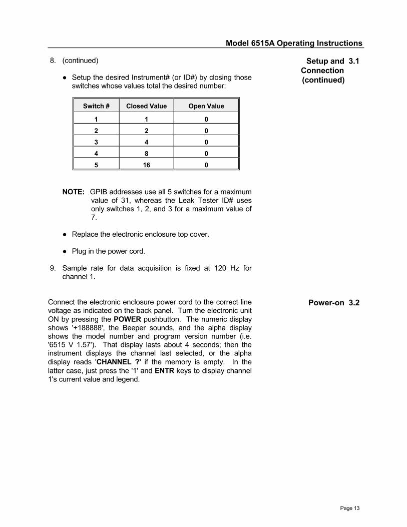
● Setup the desired Instrument# (or ID#) by closing thoseswitches whose values total the desired number:
NOTE: GPIB addresses use all 5 switches for a maximumvalue of 31, whereas the Leak Tester ID# usesonly switches 1, 2, and 3 for a maximum value of7.
● Replace the electronic enclosure top cover.
● Plug in the power cord.
9. Sample rate for data acquisition is fixed at 120 Hz forchannel 1.
Setup and 3.1Connection(continued)
Connect the electronic enclosure power cord to the correct linevoltage as indicated on the back panel. Turn the electronic unitON by pressing the POWER pushbutton. The numeric displayshows '+188888', the Beeper sounds, and the alpha displayshows the model number and program version number (i.e.'6515 V 1.57'). That display lasts about 4 seconds; then theinstrument displays the channel last selected, or the alphadisplay reads 'CHANNEL ?' if the memory is empty. In thelatter case, just press the '1' and ENTR keys to display channel1's current value and legend.
Power-on 3.2
Switch # Closed Value Open Value
1 1 02 2 03 4 04 8 05 16 0

Model 6515A Operating Instructions
Page 14
Model 6515A Operating Instructions
Page 15
This section covers operation of the Leak Tester from the frontpanel of the electronic enclosure, and remotely from a hostcomputer.
OPERATION 4
There are 2 modes of keyboard operation; Operate andProgram. Leak testing is done in the Operate mode. TheProgram mode allows an authorized user to change parametersfrom the keypad.
The Program mode is entered by pressing the PGRM key,entering the number 473 in response to the "CODE ?" prompt,and pressing ENTR. "PGM CH nn" appears on the alphadisplay, where nn is the channel number. One can exit Programmode by pressing the OPER and ENTR keys.
When the START pushbutton is pressed to begin another Leaktest, the mode is automatically forced to Operate.
Operating Modes 4.1
This section describes the Leak test parameters. Theseparameters can be programmed through the keypad, or remotelyvia a computer or CRT terminal. Once entered, the values areretained in battery-backed memory. With the 10 Selector optionten sets of parameter values are retained. One must be inProgram mode to enter parameters via the keypad.
The LEAK PARM key gives access to the Leak Testerparameters.
● in Program mode, press the LEAK PARM key.
● if the Leak Tester has the 10 Selector option, the alphadisplay shows "SELECTOR # ?". Key in the desiredSelector number, 1 to 10, and press ENTR. This entry doesnot affect the Selector number used in the next test. ForLeak Testers without the 10 Selector option, this prompt isskipped.
● alpha display shows "FILL SEC. ?" - key in the number ofseconds to keep the Fill Valve open, then press ENTR. Thenew value now shows on the numeric display; if it is correct,press ENTR to accept it; otherwise key in the desirednumber and press ENTR.
Entering Test 4.2Parameters
Model 6515A Operating Instructions
Page 16
4.2 Entering Test Parameters (continued)
● alpha display shows "STABIL.SEC.?" - key in the numberof seconds to allow the thermal effects to settle beforebeginning the Test phase, then press ENTR. Correct asnecessary and then accept with an ENTR.
● alpha display shows "TEST SEC. ?" - key in the duration(up to 99,999 seconds) of the Test phase, then pressENTR. Correct as necessary, and accept with an ENTR.
● alpha display shows "TEST PRESS.?" - key in theminimum pressure (vacuum) to be achieved in the Fillphase, and press ENTR. Correct as necessary, and acceptwith an ENTR. This value is used in the correction due tothe transducer diaphragm deflection (see Section 10,Advanced Options).
● alpha display shows "VOL(CU.IN.)?" - key in the volume, incubic inches, of the unit under test and the associatedplumbing (see Appendix II), then press ENTR. Correct asnecessary and accept with ENTR.
● alpha display shows "CC/SEC" or "CC/MIN" or "CU.IN/SEC"or "CU.IN/MIN" or "PSI/SEC" or "PSI/MIN" or "INH2O/SEC"or "INH2O/MIN" or "PSI" or "IN.H2O" or "CUSTOM UNITS";press the ± key to step through them, and select the oneyou want by pressing ENTR when the desired unit-name isshowing. See Table 1 for the associated LEAKCONSTANTs. If you choose CUSTOM UNITS, you mustenter a LEAK CONSTANT below.
● alpha display shows "LEAK CONST.?" - when CUSTOMUNITS is chosen, key in your leak units conversion constant(see Appendix I) and press ENTR. Correct as necessaryand accept with ENTR. Remember to name the new unitsby setting the channel 3 legend.
● alpha display shows "HI LEAKRATE?" - key in the largestacceptable leak rate, then press ENTR. Leak rates abovethis value will cause the test to fail. Correct as necessaryand accept with ENTR.
● alpha display shows "LO LEAKRATE?" - key in thesmallest acceptable leak rate and press ENTR. Correct asnecessary and accept with ENTR. If this optional parameteris not entered, no low limit checking is done on the leak rate.
Model 6515A Operating Instructions
Page 17
The Adiabatic Correction is a parameter that is subtracted fromthe pressure drop when the leak rate is calculated. This allowsone to compensate for a repeatable, predictable, temperatureinduced pressure drop during the Test phase. To put in avalue,
● in Program mode, press ADB CORR key
● if the Leak Tester has the 10 Selector option, the alphadisplay shows "SELECTOR # ?" - key in the desiredselector number, 1 to 10 and press ENTR. This entry doesnot affect the Selector number used in the next test. ForLeak Testers without the 10 Selector option, this prompt isskipped.
● alpha display shows "ADIAB.CORR.?" - enter the newvalue, press ENTR to see it in the numeric display. Reenterif necessary, and press ENTR to accept and store thisvalue.
The Leak Tester can also calculate and store an AdiabaticCorrection that is the average of the pressure drops of the last 4Leak tests. These Leak tests should be done using 4 known,non-leaking test items. If only one non-leaker is available, itshould be tested 4 times, allowing enough time between testsfor the item to reach temperature equilibrium.
● in Program mode, press the ADB CORR key
● if the Leak Tester has the 10 Selector option, the alphadisplay shows "SELECTOR # ?" - key in the desiredselector number, 1 to 10 and press ENTR. This entry doesnot affect the Selector number used in the next test. ForLeak Testers without the 10 Selector option, this prompt isskipped.
● alpha display shows "ADIAB.CORR.?" - the current value isdisplayed. Press ENTR to calculate, store, and display thevalue of the New Adiabatic Correction. Press ENTR againto exit the ADB CORR sequence.
NOTE: If fewer than 4 pressure drops are found, " TOOFEW " is displayed, and the Adiabatic Correctionremains unchanged.
Entering Test 4.2Parameters(continued)

Model 6515A Operating Instructions
Page 18
4.2 Entering Test Parameters (continued)
NOTE: If you need the leak rate displayed in units not shownin Table 1, see Appendix I, and change the channel 3legend appropriately.
The Delay Factor delays Pass/Fail/Gross Logic Output signalsfor a downstream line station. The Delayed status becomesvalid when a test completes and stays until the next testcompletes. A Delay of 0 provides the status of the latest test; aDelay Factor of 2 provides the status of 3 tests ago. To set theDelay Factor:
● in Program mode, press the SCAN key
● alpha display shows " RATE ?" - press ENTR to bypass thisscan 'seconds-per-channel' rate number.
● alpha display shows "LOGIC DELAY?" - this is the DelayFactor; enter a number in the range of 0 to 16 and pressENTR. The new value will then show in the numeric display;change it if needed and press ENTR to accept it.
● alpha display shows "RES.QUE OK" - press ENTR to skipthe Results Queue clear. To clear the Results Queue,press ± key to show "CLR RES.QUE", then press ENTR.
Table 1LEAK CONSTANTS FOR
PROVIDED UNITS OF LEAKAGE
Units of Calculated Leak Leak Units Constant
cc/sec 1.115
cc/min 66.9
cubic in/sec 0.06803
cubic in/min 4.0822
psi/sec 1
psi/min 60
inches H2O/sec 27.684
inches H2O/min 1661
psi 1
inches H2O 27.684
Model 6515A Operating Instructions
Page 19
● alpha display shows "CLR MEMORY ?" - press ENTR toskip the memory clear and end the SCAN sequence.Memory clear is reserved for SHC factory use.
CAUTION! When memory is cleared, all parametersincluding Kp, Vref, and PAUSE TIME are set todefault values or cleared. Kp, Vref, andPAUSE TIME are hidden in the LEAK PARMkey sequence. Section 10, Advanced Options,describes programming these parameters.
Entering Test 4.2 Parameters
(continued)
1. Set the FILL TIME to 9999 seconds, press START.2. Adjust the regulator to the minimum acceptable TEST
PRESSURE.3. The red light on the pressure switch cover is ON when the
pressure is below the switch setting. Turn the pressure switchcollar to higher numbers until the red light extinguishes. Thisis the appropriate setting.
4. Press the ABORT switch to terminate the test and restore thepneumatic valves to their normal positions.
5. Restore the FILL TIME to the normal value
Setting the Pressure 4.3Switch
After the test volume is plumbed, set the Selector number (if theLeak Tester has the 10 Selector option) to the desired value withthe SEL# UP or SEL# DOWN key or the external Selector lines,and start the Leak Tester by pressing the START button on thefront of the electronic enclosure, or asserting the external STARTsignal. The Leak test, consisting of Fill (or Evacuate),Stabilization, and Test phases, is performed automatically. Ifsome of the Test Parameters are missing, the NO PARAMETERmessage is displayed.
During the Leak test, the differential pressure is displayed on thenumeric display, the TEST indicator is lit, and the OK, FAIL, andGROSS indicators are off. At the end of the Test phase, theTEST indicator goes off, and the OK and FAIL indicators reflectthe status of the test, i.e., whether it passed or failed. Should thetest item be a gross leaker -- one in which the pressure dropsbelow the pressure switch trip level during the Stabilizationphase -- the GROSS and FAIL indicators are lit. At the end of thetest, the test volume is automatically vented and may be removedfrom the fixture. A new test volume is plumbed and the automaticcycle is repeated as described above.
A test can be aborted by pressing the ABORT switch. No recordis kept of that test. Once a test is completed, the data for that testare stored in memory. Data from the most recent 300 tests areretained. This feature is useful when a computer
Running a Leak Test 4.4
Model 6515A Operating Instructions
Page 20
4.4 Running a Leak Test (continued)
collects data from the Leak Tester. The retained test datainclude the system ID number, day of year, time of day, selectornumber (used with 10 Selector option, leak rate, aPass/Fail/Gross Leak flag (the letter P or F or G), the number ofpassing parts, the number of failing parts, and the total numberof parts tested since the counters were reset. When Gross Leakis declared, the value of the leak rate is stored as 99999.
4.5 Calibration Check The operator can check calibration as follows:
1. Select channel 1 for display, observe that the pressure iszero. If not, adjust the ZERO pots.
2. Press the CAL pushbutton, observe that the pressuredisplayed agrees with the transducer Data Sheetcalibration value. If not, adjust the SPAN pots.
3. Connect a known non-leaker as the unit under test.4. Run a test (refer to the preceding section). Result of the
test should be OK.5. Connect a known leaker as the unit under test (UUT).6. Run a test. Result of the test should be FAIL.
The Leak Tester was factory calibrated with the deliveredpressure transducer, amplifier, and interconnecting cable.
Only when an amplifier or transducer is replaced, or adifferent length or type of cable is used, must the system berecalibrated.
See Section 9, Calibration Procedure, to recalibrate.
4.6 Printouts Leak Tester printouts are designed to fit in 40 columns, exceptfor the Header lines which can be up to 50 characters long. Four kinds of printouts are produced by the Leak Tester:
Queue PrintoutSummary PrintoutCondensed PrintoutRegular Printout
A Queue Printout is initiated by pressing the QUE PRNT key. Itprints whatever test data is in the Results queue, along with acolumn header - see Figure 6.
A Summary Printout is initiated by pressing the SUMR PRNTkey or by asserting the SUMMARY PRINT logic input. It printsthe user-programmable header, time and date, the Leak testparameters, and test result statistics - see Figure 5.
A Condensed Printout (see Figure 4) prints a single line of themost recent test data from the Results queue.
Model 6515A Operating Instructions
Page 21
A Regular printout (see Figure 3) consists of auser-programmable header, time and date, and, one line foreach channel containing channel number, the channel value atthe end of the last test, and the legend.
The Condensed and Regular printouts can be initiated by thePRNT key or the external PRINT signal, and by the completionof each test, if desired. The keyboard sequence below coversthe Leak Tester printout selection and, where applicable,programming.
First, enter Program mode, then:
● Press the PRNT key.
● Alpha display shows "1ST CHAN ?" - key in the number ofthe first channel to appear on the Regular printout and pressENTR. The new value appears on the numeric display;press ENTR to accept it.
● Alpha display shows "LAST CHAN ?" - key in the numberof the last (highest numbered) channel to be included on theRegular printout, or else press ENTR to use the previouslyentered value (which is not shown).
● Alpha display shows "DELETE ?" - this allows you to deletefrom the Regular printout one or more channels in the "1STCHAN to LAST CHAN" range. To delete a channel, enter achannel number and press ENTR; repeat this sequenceuntil no more channels need deleting, then press ENTR.
● Alpha display shows "INCLUDE ?" - this allows re-instatinga previously deleted channel. Just press ENTR to skip this.
● Alpha display shows "CONDENSED " or "REGULARPRNT" - select the type of printout for the PRNT commandand End-of-test. Press the ± key to change your choice.Then press ENTR when the name of the desired printformat appears.
● Alpha display shows "NO PRNT TEST" or "PRNT ENDTEST" - to get a Condensed or Regular printout after everytest completion, press the ± key until "PRNT END TEST"appears, then press ENTR. To omit the printing after everytest, press ENTR when "NO PRNT TEST" appears.
Printouts (continued) 4.6
Model 6515A Operating Instructions
Page 22
4.6 Printouts (continued) ● Alpha display shows "HEADING " - this prompts the entry ofup to 50 alphabetic and numeric characters for the Headingof the Regular and Summary printouts (see the "ALPH"paragraph in Section 2.4, Keypad). Enter the heading (ifany) and press ENTR. Until you enter a heading, a built-inheading, as seen in Figure 3, is used.
● Alpha display shows "PRINTR BAUD?" - allows the printerBaud rate to be changed. Acceptable Baud rates are 110,300, 600, 1200 (the standard for SHC-supplied printers),2400, 4800, 9600, 19200 (entered as 1920), and 38400(entered as 3840). Enter a Baud rate and press ENTR. Press ENTR again to accept it.
● Alpha display shows "I/O BAUD?" - key in the Baud rate(from the above list) that the host computer will use(normally 9600); press ENTR to display the new value, andpress ENTR again to accept it.
● Alpha display shows "# OF BITS ?" - key in a 7 or 8 if youwish to change the existing value, then press ENTR twice.
● Alpha display shows "EVEN PARITY" or "ODD PARITY" or"NO PARITY" - press the ± key until the desired parity typeappears. Then press ENTR to end the PRNT sequence. Even parity is used in the SHC DAPS program.
The default values for the above communication parametersare:
1200 Baud for printer8-bit characters, No parity for printer9600 Baud for I/O port7-bit characters, Even parity for I/O port
Model 6515A Operating Instructions
Page 23
The Leak test parameters can be entered (along with otherinformation) via serial or optional GPIB communication ports.The following paragraphs describe the Leak Tester's commands.
NOTE: In the formal command descriptions below, ~ stands forLine Feed, and ss stands for the Selector#, 1 to 10.
KPnn Scale Constant~set the Scaling Constant for channel nn.Example: KP01 2.5E-1~set channel 1 Scaling Constant to 0.25.
TTssFill_Time,Stab.Time,Test_Time,Test_Press,Over_Press,Test_Volume,Leak_Const or Units Name~Example: TT01 1,2.2,3,5,0,66,1.115~Example: TT01 1,2.2,3,5,0,66,CC/SEC~For Selector #1, set fill time to 1.0 sec., stabilization time to2.2 seconds, test duration to 3.0 seconds, test pressure to5.0 psi, over pressure (unused) to 0 psi, test volume to 66cubic inches and leak units constant to 1.115. Example #2shows how a leak-unit name can be used in place of a value;the corresponding value from Table 1 is used in subsequentchannel 3 computations. The accepted unit names are:CC/SEC, CC/MIN, CU.IN/SEC, CU.IN/MIN, PSI/SEC,PSI/MIN, INH2O/SEC, INH2O/MIN, PSIb, and IN.H2O. Theb in PSIb stands for a space, because every name must beat least 4 characters long.
NOTE: For Test Volume, use the sum of the volumes for theUnit Under Test, test hose, and the internal plumbing(listed in Appendix II).
TLss High Limit On Leak Rate~Example: TL02 6.67~set the Selector #2 upper Leak rate limit to 6.67.For Leak Testers with the 10 Selector option, ‘ss’ can be 01to 10. Otherwise use 01.
TMss Low Limit On Leak Rate~Example: TM02 -4.66~set Selector #2, lower Leak rate limit to -4.66.For Leak Testers with the 10 Selector option, ‘ss’ can be 01to 10. Otherwise use 01.
TSss Adiabatic Correction~Example: TS03 .0012~set the Selector #3 Adiabatic Correction to 0.0012 PSI.(Units must be the same as channel 1) For Leak Testers withthe 10 Selector option, ‘ss’ can be 01 to 10. Otherwise use01.
Remote I/O with 4.7Host Computer
or Terminal
Model 6515A Operating Instructions
Page 24
4.7 Remote I/O with Host Computer or Terminal (continued)
TXyy ~(where yy is the Delay Factor)Example: TX03 ~set Delay Factor to 3, and erase Leak Test Results queue.Example: TX99 ~leave Delay Factor unchanged, and erase Results queue.
MDEL?~request the Leak Tester to identify itself.Example, sending MDEL?~ will get a reply of:S. H. C. MODEL 6515 V 1.57
DATE mm-dd-yy~set the month, day and year numbers (2 digits each).Example: DATE 08-16-99~
TIME hr.mn.sc~set Leak Tester hour (24-hour clock), minute, and second.
RSss ~for Selector 'ss', reset the counter channels 5, 6, 7, 8, and15; erase the calculated channels 9 through 14 and 16; andclear the maximums and minimums. For Leak Testers withthe 10 Selector option, ‘ss’ can be 01 to 10. Otherwise use01.
QDnnn?~fetch one Result stored in the Leak Tester queue. 'nnn'stands for the digits 000 through 299, where 000 refers tothe newest Result, and larger numbers refer to successivelyolder Results. Each time QDnnn? is sent, there is a reply;either a line of data as shown in Figure 7, or the errormessage ER01 INVALID COMMAND (indicating that theLeak Tester didn't recognize the command), or the errormessage ER05 NONE, signifying that there is no Resultstored corresponding to the specified 'nnn'. To gather thelatest Results, merely send QD000? and save the reply,send QD001? and save the reply, etc., until a reply is foundthat is the same as a previously-gathered reply, or until theER05 message is received. If an ER01 is received, resendthe last command.
PHED string~set 'string' as the Print Header (50 characters maximum) thatwill appear on top of Regular and Summary printouts.Example: PHED AIR BAG TEST Model 671A~
Model 6515A Operating Instructions
Page 25
BAUD rrrr~set the printer port Baud rate to 'rrrr'. Choices of Baud rateare 110, 300, 600, 1200, 2400, 4800, 9600, 1920 (for19,200 Baud), and 3840 (for 38,400 Baud).Example: BAUD 2400~
PFff ~set the 1st channel to print (on Regular printout) to 'ff'.Example: PF02 ~set '2' as the first channel to appear on the printout.
PLll ~set 'll' as the last channel on the Regular printout.Example: PL13 ~set the last channel to be printed to 13.
SCAN aa,bb;cc,dd~request the Leak Tester to transmit the value from the lastLeak test and channel number of each channel in the ranges'aa' to 'bb' and 'cc' to 'dd', where 'aa' and 'bb' and 'cc' and 'dd'are 1 or 2 digits, and the first channel number of each rangeis no larger than the last. See Figure 8.Example: SCAN 1,1;3,3;5,6~transmit data for channels 1, 3, 5, and 6.Example: SCAN 3,10~transmit data for channels 3 through 10.
SCss aa,bb;cc,dd~operates like SCAN, except the data comes from the latesttest for Selector 'ss'. For Leak Testers with the 10 Selectoroption, ‘ss’ can be 01 to 10. Otherwise use 01.
LGnn AAAAAAAAA~set a legend 'AAAAAAAAA' of 9 alphanumeric characters forchannel 'nn'.Example: LG03 CFM~set CFM followed by 6 spaces as the legend forchannel 3.
NOTE: By sending the first 4 characters of these commands(except for SCAN, SCss, and RSss) with a questionmark as the 5th character, the current values of theassociated parameters are transmitted as the reply. Forexample, sending TT01?~ will get a reply of:
TT01 +1.0000 +2.2000 +3.0000 +5.0000 +6515.0 +66.000+1.150~ The Overpressure field in the TT command is alwaysset to “6515.0”.
Remote I/O with 4.7Host Computer
or Terminal(continued)

Model 6515A Operating Instructions
Page 26
4.8 TIME and LEGEND Keys
● press TIME key (in Program mode)
● alpha display shows "AM TIME?" or "PM TIME?" and thenumeric display shows hours, minutes and seconds. Toskip to the Date, press ENTR. To change the time, enterhours (0 through 23), minutes, and seconds (separated byperiods) and press ENTR. The new time is displayed, and"AM TIME" or "PM TIME" will show in the alpha display. Press ENTR to accept time. Then the alpha display shows" DATE ?" - press ENTR to accept the current date. Tochange it, enter the month, day of the month, and last 2digits of the year, separated by periods. Then press ENTRto verify it in the numeric display, and press ENTR again toaccept the new value.
● press LGND key (in Program mode)
● alpha display shows "LEGEND ?"; enter the characters forthe new legend and press ENTR. Only the first 9 charactersare accepted. See the ALPH key information in Section 2.4,Keypad, for entering non-numeric information through thekeypad.
FIGURE 3 SAMPLE'REGULAR' PRINTOUT
S.H.C. MODEL 6515 V 1.57
09:26:54 06/26/99 CH VALUE UNITS
01 +3.5500 PSI 02 +0.0450 PSI DROP 03 +14.567 CC/SEC replaced by 04 +00001 RESERVED SELECTOR # 05 +00044 OK PARTS on Leak Testers 06 +00048 TOTAL with 10 Selector Option 07 +00003 BAD PARTS 08 +00001 GR LEAKS 09 +03.95 TEST PSI User-entered value 10 +91.67 % PASS 11 +08.330 % FAIL 12 +45.677 MAX LEAK 13 +0.0000 MIN LEAK 14 +45.677 SPREAD 15 +00047 LOT SIZE 16 +12.443 AVG LEAK 17 +7.4332 STD DEV

Model 6515A Operating Instructions
Page 27
226 09:26:54 01 +03.950 +14.567 PASS
STATUS FLAGLEAK RATE
TEST PRESSURE(user-entered value)
SELECTOR NUMBER(used with 10 Selector option)
TIME OF DAY (24 hr. clock)DAY OF YEAR
FIGURE 4 SAMPLE'CONDENSED'
PRINTOUT
LEAK TEST SUMMARY S.H.C. MODEL 6515 V 1.57 FIGURE 5 SAMPLE'SUMMARY' PRINTOUT
08:12:44 06/26/99FILL TIME = +1.0000 SEC.
STABILIZE TIME = +2.0000 SEC.TEST TIME = +2.7000 SEC. This line is added on
PAUSE TIME = +0.2000 SEC Leak Testers withSELECTOR # = 01 the 10 Selector option
TEST PRESSURE = +09.000 PSI Test Pressure is aXDUCER DEFLECT = +.00146 CU.IN/PSI user entered value
REFER VOLUME = +0.6000 CU.IN.TEST VOLUME = +16.445 CU.IN.
LEAK CONSTANT = +1.1150HIGH LEAK RATE = +44.000 CC/MINLOW LEAK RATE = -6.6667 CC/MIN
ADIABATIC CORR = +1.2000E-02 PSI
# OK =+00004 # BAD =+00001# GROSS =+00001 # TOTAL =+00006
% PASS =+66.667 % FAIL =+33.333
LOT SIZE =+00005 AVG LEAK =+2.4688MAXIMUM =+14.375 MINIMUM =-1.2000
SPREAD =+15.575 STD DEV =+1.3750

Model 6515A Operating Instructions
Page 28
FIGURE 6 SAMPLE'QUEUE' PRINTOUT
DAY# TIME SEL TEST-PR LEAK-RATE STAT 226 02:18:21 01 +05.250 +4.0883 PASS 226 02:18:03 01 +05.250 +48.224 FAIL 226 02:17:46 01 +05.250 +99999 GROS
user-entered values
used with the 10 Selector option
FIGURE 7 'QD FORMAT'FOR REMOTE I/O
6 226 09:26:54 01 +03.950 +14.567 P 0011 0001 0012
LEAK RATETEST PRESSURE
(user-entered value)SELECTOR # PASS/FAIL(10 Selector option) GROSS
TIME OF DAY # GOOD (24 hr. clock)
DAY OF YEAR # FAILEDLEAK TESTER ID# TOTAL PARTS
FIGURE 8 SAMPLE'SCAN' DATA FORREMOTE I/O
03,+14.56704,+0000105,+0004406,+00048
Model 6515A Operating Instructions
Page 29
Two serial RS-232-C interfaces are provided; one is a printerport, and the other is the ASCII Input/Output for communicatingwith a host computer or a remote terminal. In addition, anoptional high-speed parallel General Purpose Instrument Bus(GPIB) can be provided.
COMMUNICATION 5INTERFACES
In the Model 6515 Leak Tester, printouts are transmitted via theRS-232-C output which is available on the external I/Oconnector J6. These printouts may be generated automaticallywhen a test finishes, when the PRNT button is pressed, or whenthe external PRINT signal is asserted.
Any RS-232-C computing device, terminal, or printer will acceptthe Printer Port output. No special characters, other thancarriage return, line feed, and form feed, are transmitted (unlessthey are programmed into the printout header). Sampleprintouts are shown in Figures 3, 4, 5 and 6. The programversion number and the Instrument model number are printed inthe default header (see Figure 3), which is replaced by theuser-installed print header.
Each transmitted character is sent asynchronously in bit-serialfashion, with 1 start bit, an 8-bit character, no parity bit, and 1stop bit (2 stop bits are used if the Baud rate is 110 or less). Pinassignments are listed in Section 6, Specifications andElectrical Loads.
Printer Port 5.1
The RS-232-C ASCII Input/Output allows the Leak Tester tosend data and parameters to a host computer (or terminal), andallows the host computer (or terminal) to send (download)programmable parameters to the Leak Tester. Mostparameters that can be entered from the keyboard can also bedownloaded from the host computer. See Section 4.7, RemoteI/O with Host Computer or Terminal, for the Remote commandsthat control information transfer between the Leak Tester andthe host computer (or terminal).
Every transmission is ended with an EOT (04) character tosignal that the Leak Tester has completed the transmission.
ASCII Input/Output 5.2

Model 6515A Operating Instructions
Page 30
5.2 ASCII Input/Output (continued)
The Leak Tester processes one I/O command at a time, andresponds to every command, either with the desired informationor an error message. To prevent overloading, the hostcomputer should always wait for a reply before issuing anotherI/O command. Host computers that cannot accept all theinformation as fast as the Leak Tester sends it, can inhibitfurther transmission by removing their 'Request To Send' signal.The Baud rate, character length, and parity are set at the LeakTester keypad. Default values and pin assignments are listed inSection 6, Specifications and Electrical Loads.
5.3 General Purpose Instrument Bus
This bus (also called the IEEE-488 bus) was developed toprovide a standard means for communicating with, and among,programmable instruments. It allows connection of varioustypes of instrumentation through a simple "plug-compatible"high speed bus. A maximum of 15 "instruments" may beconnected to one bus through special cables that total 20meters at most. The GPIB carries the same commands,parameters, and data as the serial interface; see Section 4.7,Remote I/O with Host Computer or Terminal, for thecommands. The GPIB cable attaches at the J4 port on theback of the electronics enclosure.

Model 6515A Operating Instructions
Page 31
DIMENSIONS:Electronic Enclosure: 8.6" W, 3.5" H, 19" DPneumatic Enclosure: 12.0" W, 14.0" H, 8" D
POWER:Electronic Enclosure: 105-130 VAC, 50-60 Hz, 70 VA
OPERATOR CONTROLS:POWER On/Off, START, ABORT
DISPLAY:Data: 5 digit LEDsInfo: 12 character LEDs
INDICATORS:TEST, OK, FAIL, GROSS
PARTS COUNTERS:Separate counts of Good, Bad, Gross Leak and Total Parts to99,999 maximum can be displayed; the low 4 digits are outputin the "QD FORMAT" (see Figure 7).
LOCAL MEMORY:Queue of last 300 Tests with Date & Time
COMMUNICATIONS:RS-232C duplex and serial printer portsBaud rate selectable from 75 to 38400.Defaults are: 9600 Baud for the ASCII I/O port; 1200 Baud for the printer port; 8-bit character, No parity for printer; 7-bit character, Even parity for ASCII I/O.
DIGITAL INPUTS (Edge Connector J6):START - pin EABORT - pin DPRINT - pin 8
SUMMARY PRINT - pin ARESET COUNTERS - pin H
GND - pin KSelector# 1 line - pin CSelector# 2 line - pin Z for Leak Testers withSelector# 4 line - pin Y the 10 Selector optionSelector# 8 line - pin X
All inputs are active LOW (0 to +0.8 V Max) and can be drivenby TTL signal or contact closure to GND (pin K). Input voltage(if any) should not exceed +5.0 V.
SPECIFICATIONS and 6ELECTRICAL LOADS
Model 6515A Operating Instructions
Page 32
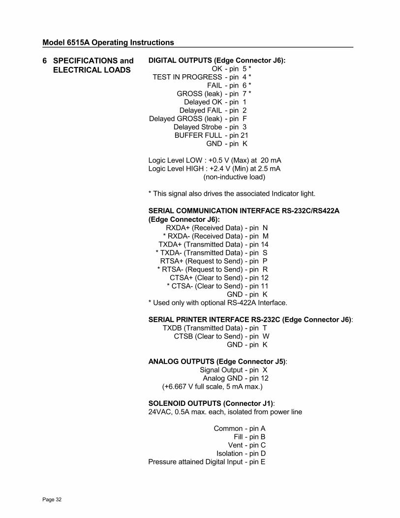
6 SPECIFICATIONS and ELECTRICAL LOADS
DIGITAL OUTPUTS (Edge Connector J6):OK - pin 5 *
TEST IN PROGRESS - pin 4 *FAIL - pin 6 *
GROSS (leak) - pin 7 *Delayed OK - pin 1
Delayed FAIL - pin 2Delayed GROSS (leak) - pin F
Delayed Strobe - pin 3BUFFER FULL - pin 21
GND - pin K
Logic Level LOW : +0.5 V (Max) at 20 mALogic Level HIGH : +2.4 V (Min) at 2.5 mA (non-inductive load)
* This signal also drives the associated Indicator light.
SERIAL COMMUNICATION INTERFACE RS-232C/RS422A(Edge Connector J6):
RXDA+ (Received Data) - pin N* RXDA- (Received Data) - pin M
TXDA+ (Transmitted Data) - pin 14* TXDA- (Transmitted Data) - pin S
RTSA+ (Request to Send) - pin P* RTSA- (Request to Send) - pin R
CTSA+ (Clear to Send) - pin 12* CTSA- (Clear to Send) - pin 11
GND - pin K* Used only with optional RS-422A Interface.
SERIAL PRINTER INTERFACE RS-232C (Edge Connector J6):TXDB (Transmitted Data) - pin T
CTSB (Clear to Send) - pin WGND - pin K
ANALOG OUTPUTS (Edge Connector J5):Signal Output - pin XAnalog GND - pin 12
(+6.667 V full scale, 5 mA max.)
SOLENOID OUTPUTS (Connector J1):24VAC, 0.5A max. each, isolated from power line
Common - pin AFill - pin B
Vent - pin CIsolation - pin D
Pressure attained Digital Input - pin E
Model 6515A Operating Instructions
Page 33
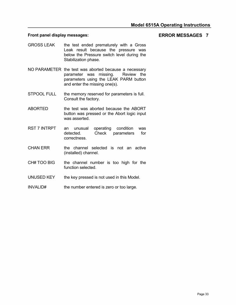
Front panel display messages:
GROSS LEAK the test ended prematurely with a GrossLeak result because the pressure wasbelow the Pressure switch level during theStabilization phase.
NO PARAMETER the test was aborted because a necessaryparameter was missing. Review theparameters using the LEAK PARM buttonand enter the missing one(s).
STPOOL FULL the memory reserved for parameters is full. Consult the factory.
ABORTED the test was aborted because the ABORTbutton was pressed or the Abort logic inputwas asserted.
RST 7 INTRPT an unusual operating condition wasdetected. Check parameters forcorrectness.
CHAN ERR the channel selected is not an active(installed) channel.
CH# TOO BIG the channel number is too high for thefunction selected.
UNUSED KEY the key pressed is not used in this Model.
INVALID# the number entered is zero or too large.
ERROR MESSAGES 7
Model 6515A Operating Instructions
Page 34
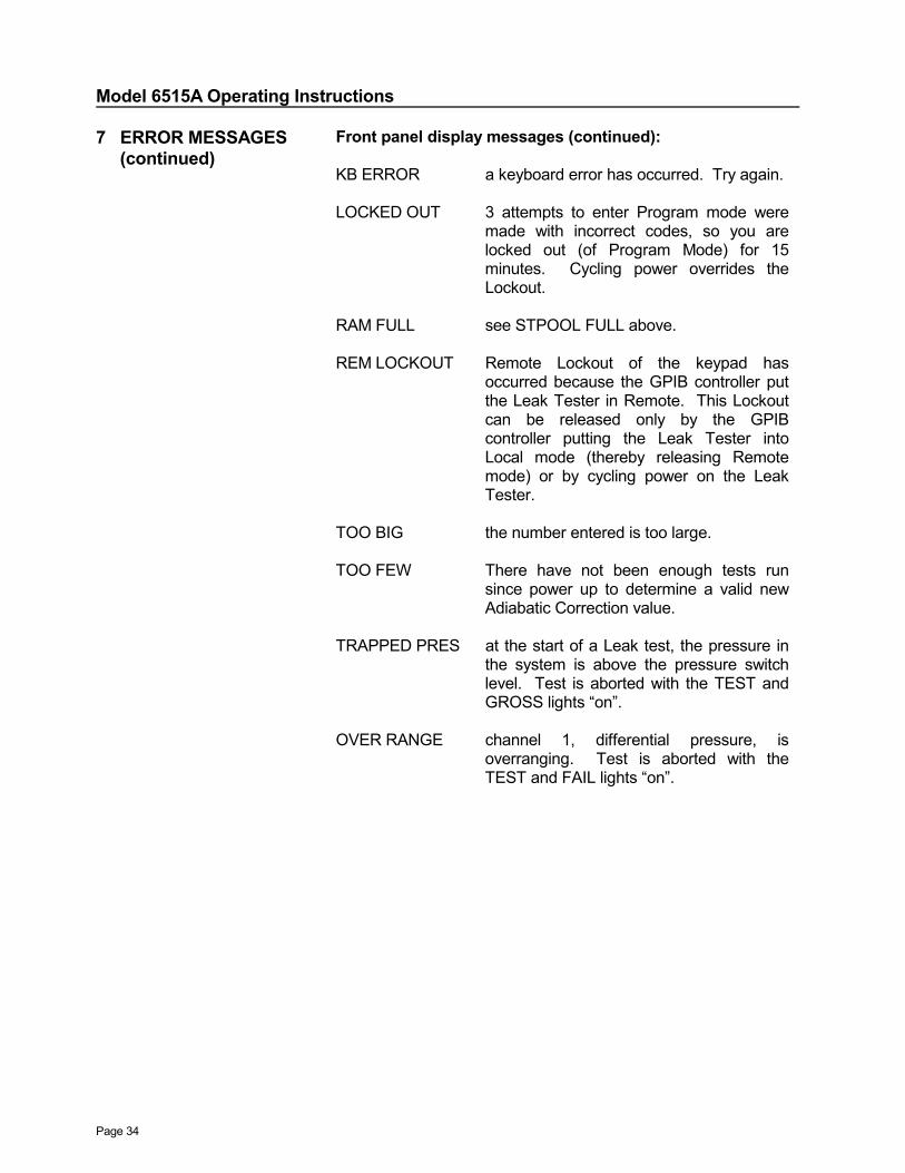
7 ERROR MESSAGES (continued)
Front panel display messages (continued):
KB ERROR a keyboard error has occurred. Try again.
LOCKED OUT 3 attempts to enter Program mode weremade with incorrect codes, so you arelocked out (of Program Mode) for 15minutes. Cycling power overrides theLockout.
RAM FULL see STPOOL FULL above.
REM LOCKOUT Remote Lockout of the keypad hasoccurred because the GPIB controller putthe Leak Tester in Remote. This Lockoutcan be released only by the GPIBcontroller putting the Leak Tester intoLocal mode (thereby releasing Remotemode) or by cycling power on the LeakTester.
TOO BIG the number entered is too large.
TOO FEW There have not been enough tests runsince power up to determine a valid newAdiabatic Correction value.
TRAPPED PRES at the start of a Leak test, the pressure inthe system is above the pressure switchlevel. Test is aborted with the TEST andGROSS lights “on”.
OVER RANGE channel 1, differential pressure, isoverranging. Test is aborted with theTEST and FAIL lights “on”.

Model 6515A Operating Instructions
Page 35
ASCII I/O error messages:
ER01 INVALID COMMANDthe Leak Tester does not recognize the command it hasreceived.
ER02 CHANNEL# OUT OF RANGEthe channel number in the command is zero or too large.
ER03 VALUE OUT OF RANGEthe numeric value is out of the acceptable or usable range.
ER04 MEMORY FULLthe memory reserved for parameters is full. Consult thefactory.
ER05 NONEthere is no data for this request.
ER06 WRONG # OF FIELDSthe TT command doesn't have seven parameters.
ER08 LAST FIELD INVALIDthe TT command's 7th field isn't a number or a recognizedunit name.
ER09 OUT OF MEMORYa SCAN command has been received while the ResultsQueue is being printed. when the printout is completed, theSCAN command will work without error.
ERROR MESSAGES 7(continued)
Model 6515A Operating Instructions
Page 36
Model 6515A Operating Instructions
Page 37
For the following description of a Leak test, please refer to thePneumatic schematic in Section 2, Circuit Documentation, ofthe manual.
At the start of the Leak test, the parameters are checked. Forunits with the 10 Selector option, the parameters for the currentSelector number are used. If any are not defined the test isaborted and "NO PARAMETER" is displayed.
If the checks pass, the Fill and Isolation valves are openedwhile the Vent valve is closed. The test volume is pressurizing(or evacuating). The numeric display is blank during the Fillphase. The TEST light is turned "on" while the OK, FAIL, andGROSS lights are turned "off".
When the FILL TIME expires, the Stabilization phase begins.The Fill valve is closed. The Isolation valve remains openedand the Vent valve remains closed. Pressure transients andthermal effects are allowed to settle during the Stabilizationphase. The differential pressure (channel 1) is displayed on thenumeric display during the Stabilization phase. If the pressurefalls below the Pressure switch level, the test is aborted and theGROSS (Gross Leak) and FAIL lights are turned "on" while theTEST light is turned "off”. This Gross Leak checking iscontinued during the Stabilization phase.
When the STABILIZATION TIME expires, the Pause phasebegins. The Isolation valve is closed. The Fill and Vent valvesremain closed. Pressure transients due to the closing of theIsolation valve are allowed to settle.
When the PAUSE TIME expires, the Test phase begins. TheFill, Isolation, and Vent valves remain closed. The differentialpressure (channel 1) is zeroed. The TEST TIME remaining isdisplayed on the alpha display, while the differential pressure isdisplayed on the numeric display.
THEORY OF 8 OPERATION
Model 6515A Operating Instructions
Page 38
8 THEORY OF OPERATION (continued)
When the TEST TIME expires, the Leak test is completed asindicated by the TEST light turning "off". The Fill valve remainsclosed while the Isolation and Vent valves are opened. The testvolume is venting. The leak rate test result (channel 3) isdisplayed and compared to the HIGH and LOW LEAK RATE’s,and FAIL or OK is indicated by the lights. The test information(system ID number, day of the year, time, selector number, testpressure, leak rate, pass/fail/gross status, and counter values)is stored in memory. The memory holds test information for thelast 300 tests. This data can be accessed by a computerconnected to the Leak Tester's serial I/O port or GPIB port. Also, delayed logic outputs are asserted at the end of each testto signal OK, Fail, or Gross Leak; this occurrence may bedelayed up to 16 tests by setting the Delay Factor. When thedelayed outputs are valid, they are accompanied by a Strobesignal.
A Leak test can be aborted during any phase by pressing theABORT button, asserting the external ABORT signal, or anOVERPRESSURE condition. The Fill valve is closed while theIsolation and Vent valves are opened. The test volume isvented. The TEST and FAIL lights are turned "on".
Seventeen channels are implemented for the Leak Tester:
● Channel 1 is the differential pressure transducer; units arePSI.
● Channel 2, corrected pressure drop during the Test phase, iscalculated at the end of each test. The correction factorcompensates for the transducer diaphragm deflection (seeSection 10, Advanced Options). Channel 2 has the sameunits as channel 1.
● Channel 3 is the calculated leak rate, whose equationdepends on the units selected.
For units of volume/time (CC/SEC, CC/MIN, CU.IN/SEC,CU.IN/MIN, and CUSTOM UNITS) the equation is:
( )ADB.CORR.-CH2 xTIME TEST
CONSTANT LEAK x VOLUME TEST =CH3
For units of pressure/time (PSI/SEC, PSI/MIN, INH2O/SEC,and INH2O/MIN) the equation is:
( )CORRECTION.ADB2CH x TIME TEST
CONSTANT LEAK =CH3 −
Model 6515A Operating Instructions
Page 39
For units of pressure (PSI and INH2O) the equation is:
)CORRECTION.ADB(CH2 x CONSTANT) (LEAK =CH3 −
● Channel 4 displays the Selector number on Leak Testers withthe 10 Selector option.
● Channels 5 through 8 are counters that keep track of totalparts tested (CH6), good parts (CH5), failed parts (CH7), andgross leaking parts (CH8). These counters (along with CH15)are reset by the RSET CNTR key, the RSET remotecommand and the Reset Counters logic input.
● Channel 9 holds the expected Test Pressure. This value isuser-entered and is used in the calculation of the correctiondue to the transducer diaphragm deflection (see Section 10,Advanced Options).
● Channel 10 shows the percentage of parts that passed. Theformula is:
6CH100 x CH5 =CH10
● Channel 11 shows the percentage of failed parts (bad andgross leakers). The formula is:
( )CH6
100xCH8CH7CH11
+=
● Channel 12 is the largest measurable leak rate calculatedsince the counters were reset.
● Channel 13 is the smallest leak rate calculated since thecounters were reset.
● Channel 14 is the 'spread' of leak rates; that is, CH12 - CH13.
● Channel 15 is the lot size used in calculating average leakrate and Standard Deviation. It is the sum of CH5 and CH7.
● Channel 16 is the average of the measurable leak rates sincethe counters were reset. Its formula is:
15CHRates Leak of =CH16 ∑
● Channel 17 is the standard deviation of the measurable leakrates. The formula is:
CH162- CH15
Rates Leak ofSquares = CH17 ∑
THEORY OF 8 OPERATION
(continued)
Model 6515A Operating Instructions
Page 40
INSERT FIGURE 2
Model 6515A Operating Instructions
Page 41
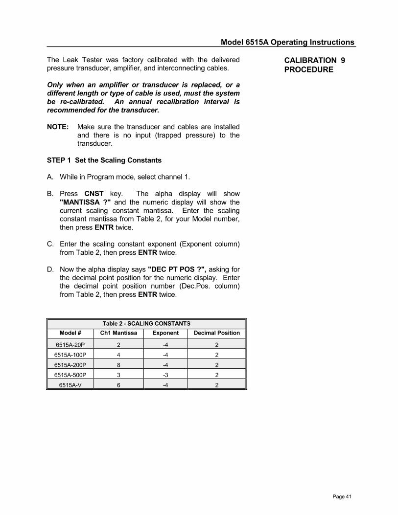
The Leak Tester was factory calibrated with the deliveredpressure transducer, amplifier, and interconnecting cables.
Only when an amplifier or transducer is replaced, or adifferent length or type of cable is used, must the systembe re-calibrated. An annual recalibration interval isrecommended for the transducer.
NOTE: Make sure the transducer and cables are installedand there is no input (trapped pressure) to thetransducer.
STEP 1 Set the Scaling Constants
A. While in Program mode, select channel 1.
B. Press CNST key. The alpha display will show"MANTISSA ?" and the numeric display will show thecurrent scaling constant mantissa. Enter the scalingconstant mantissa from Table 2, for your Model number,then press ENTR twice.
C. Enter the scaling constant exponent (Exponent column)from Table 2, then press ENTR twice.
D. Now the alpha display says "DEC PT POS ?", asking forthe decimal point position for the numeric display. Enterthe decimal point position number (Dec.Pos. column)from Table 2, then press ENTR twice.
CALIBRATION 9PROCEDURE
Table 2 - SCALING CONSTANTSModel # Ch1 Mantissa Exponent Decimal Position
6515A-20P 2 -4 2
6515A-100P 4 -4 2
6515A-200P 8 -4 2
6515A-500P 3 -3 2
6515A-V 6 -4 2
Model 6515A Operating Instructions
Page 42
9 CALIBRATIONPROCEDURE(continued)
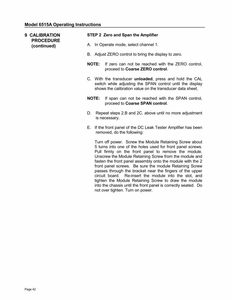
STEP 2 Zero and Span the Amplifier
A. In Operate mode, select channel 1.
B. Adjust ZERO control to bring the display to zero.
NOTE: If zero can not be reached with the ZERO control,proceed to Coarse ZERO control.
C. With the transducer unloaded, press and hold the CALswitch while adjusting the SPAN control until the displayshows the calibration value on the transducer data sheet.
NOTE: If span can not be reached with the SPAN control,proceed to Coarse SPAN control.
D. Repeat steps 2.B and 2C. above until no more adjustmentis necessary.
E. If the front panel of the DC Leak Tester Amplifier has beenremoved, do the following:
Turn off power. Screw the Module Retaining Screw about5 turns into one of the holes used for front panel screws.Pull firmly on the front panel to remove the module.Unscrew the Module Retaining Screw from the module andfasten the front panel assembly onto the module with the 2front panel screws. Be sure the module Retaining Screwpasses through the bracket near the fingers of the uppercircuit board. Re-insert the module into the slot, andtighten the Module Retaining Screw to draw the moduleinto the chassis until the front panel is correctly seated. Donot over tighten. Turn on power.
Model 6515A Operating Instructions
Page 43
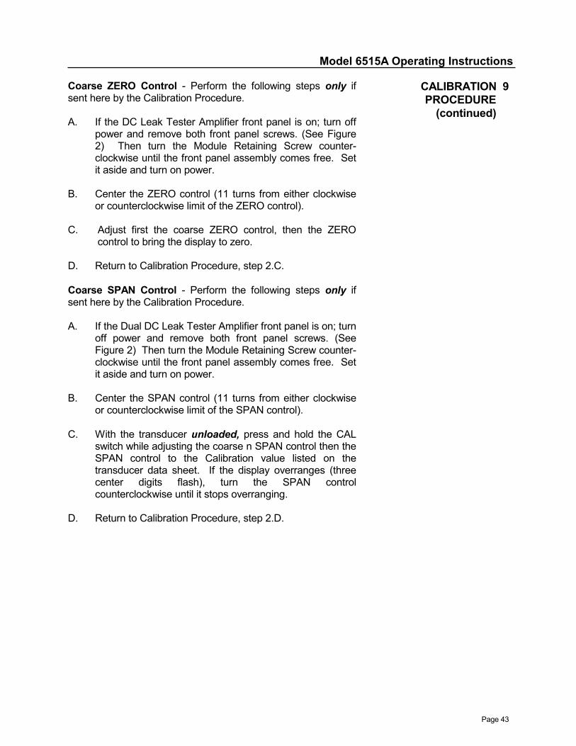
Coarse ZERO Control - Perform the following steps only ifsent here by the Calibration Procedure.
A. If the DC Leak Tester Amplifier front panel is on; turn offpower and remove both front panel screws. (See Figure2) Then turn the Module Retaining Screw counter-clockwise until the front panel assembly comes free. Setit aside and turn on power.
B. Center the ZERO control (11 turns from either clockwiseor counterclockwise limit of the ZERO control).
C. Adjust first the coarse ZERO control, then the ZEROcontrol to bring the display to zero.
D. Return to Calibration Procedure, step 2.C.
Coarse SPAN Control - Perform the following steps only ifsent here by the Calibration Procedure.
A. If the Dual DC Leak Tester Amplifier front panel is on; turnoff power and remove both front panel screws. (SeeFigure 2) Then turn the Module Retaining Screw counter-clockwise until the front panel assembly comes free. Setit aside and turn on power.
B. Center the SPAN control (11 turns from either clockwiseor counterclockwise limit of the SPAN control).
C. With the transducer unloaded, press and hold the CALswitch while adjusting the coarse n SPAN control then theSPAN control to the Calibration value listed on thetransducer data sheet. If the display overranges (threecenter digits flash), turn the SPAN controlcounterclockwise until it stops overranging.
D. Return to Calibration Procedure, step 2.D.
CALIBRATION 9PROCEDURE
(continued)

Model 6515A Operating Instructions
Page 44
Model 6515A Operating Instructions
Page 45
The Model 6515 incorporates an additional phase that allowsthe trapped pressure (on the Reference Volume side) to settleafter the ISOLATION valve is closed. The duration of thisphase is programmable, and is called PAUSE Time. Thedefault value is zero seconds.
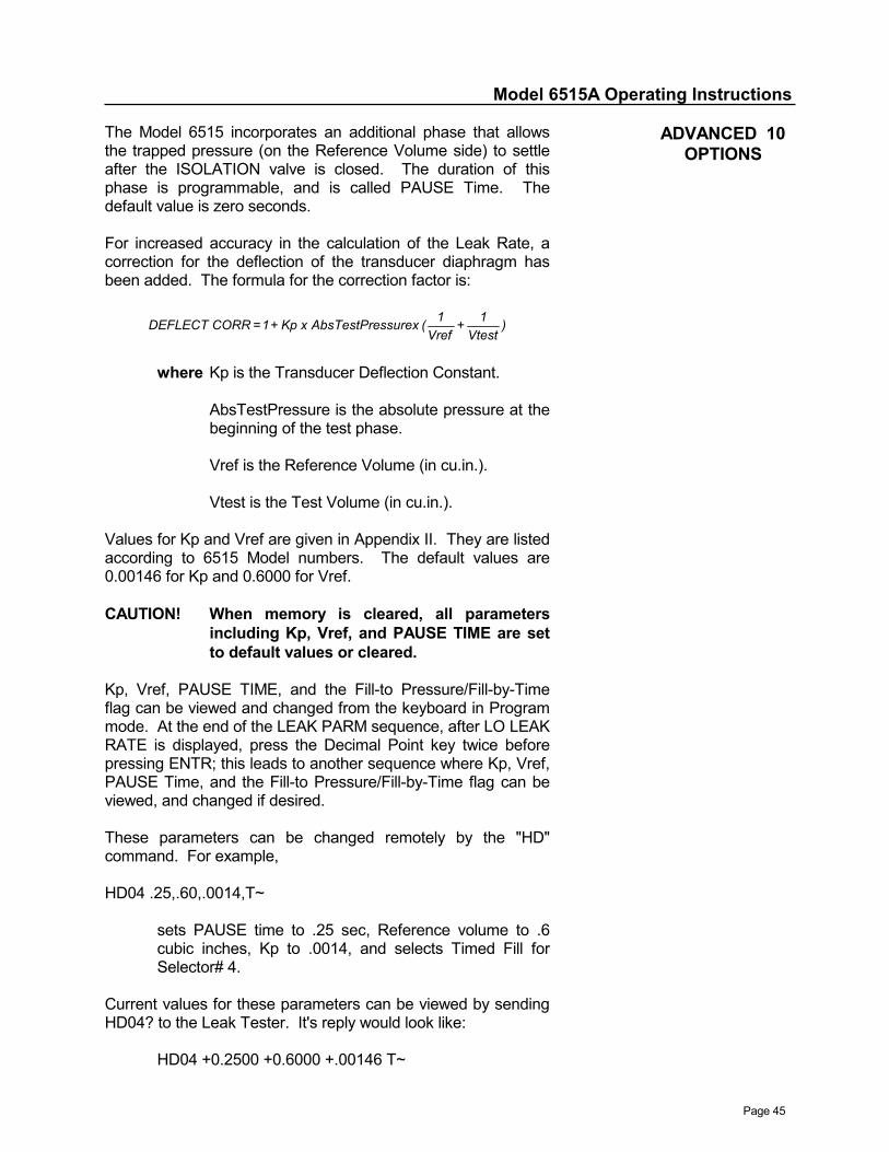
For increased accuracy in the calculation of the Leak Rate, acorrection for the deflection of the transducer diaphragm hasbeen added. The formula for the correction factor is:
)Vtest
1 + Vref
1( ssurexAbsTestPre x Kp + 1 = CORR DEFLECT
where Kp is the Transducer Deflection Constant.
AbsTestPressure is the absolute pressure at thebeginning of the test phase.
Vref is the Reference Volume (in cu.in.).
Vtest is the Test Volume (in cu.in.).
Values for Kp and Vref are given in Appendix II. They are listedaccording to 6515 Model numbers. The default values are0.00146 for Kp and 0.6000 for Vref.
CAUTION! When memory is cleared, all parametersincluding Kp, Vref, and PAUSE TIME are setto default values or cleared.
Kp, Vref, PAUSE TIME, and the Fill-to Pressure/Fill-by-Timeflag can be viewed and changed from the keyboard in Programmode. At the end of the LEAK PARM sequence, after LO LEAKRATE is displayed, press the Decimal Point key twice beforepressing ENTR; this leads to another sequence where Kp, Vref,PAUSE Time, and the Fill-to Pressure/Fill-by-Time flag can beviewed, and changed if desired.
These parameters can be changed remotely by the "HD"command. For example,
HD04 .25,.60,.0014,T~
sets PAUSE time to .25 sec, Reference volume to .6cubic inches, Kp to .0014, and selects Timed Fill forSelector# 4.
Current values for these parameters can be viewed by sendingHD04? to the Leak Tester. It's reply would look like:
HD04 +0.2500 +0.6000 +.00146 T~
ADVANCED 10OPTIONS

Model 6515A Operating Instructions
Page 46

Model 6515A Operating Instructions
Page 47
Use the formula below to calculate any Leak Units Constant:
K1K2X
psi1.115 =K3
where K1 = # of cc/Desired Volume Unit.
K2 = # of seconds/desired time unit.
K3 = new Leak Constant for desiredvolume units per desired unit oftime.
Example: Find Leak Units Constant for cubic feet per minute
cc28,316feetcubicX
min.sec60X
psi1.115 =K3
3-2.3626E =K3
APPENDIX IDetermining Leak Units
Constants
Model 6515A Operating Instructions
Page 48
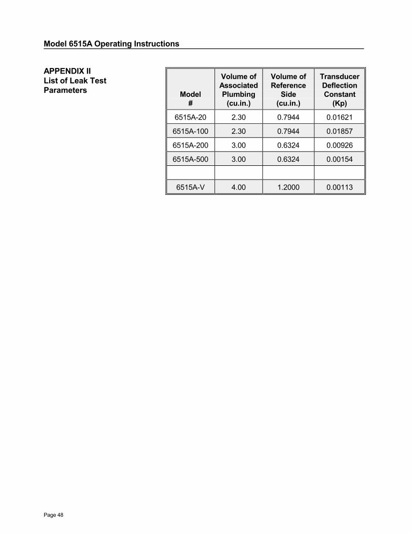
APPENDIX IIList of Leak TestParameters Model
#
Volume ofAssociatedPlumbing
(cu.in.)
Volume ofReference
Side(cu.in.)
TransducerDeflectionConstant
(Kp)
6515A-20 2.30 0.7944 0.01621
6515A-100 2.30 0.7944 0.01857
6515A-200 3.00 0.6324 0.00926
6515A-500 3.00 0.6324 0.00154
6515A-V 4.00 1.2000 0.00113