Embed Size (px)
Citation preview
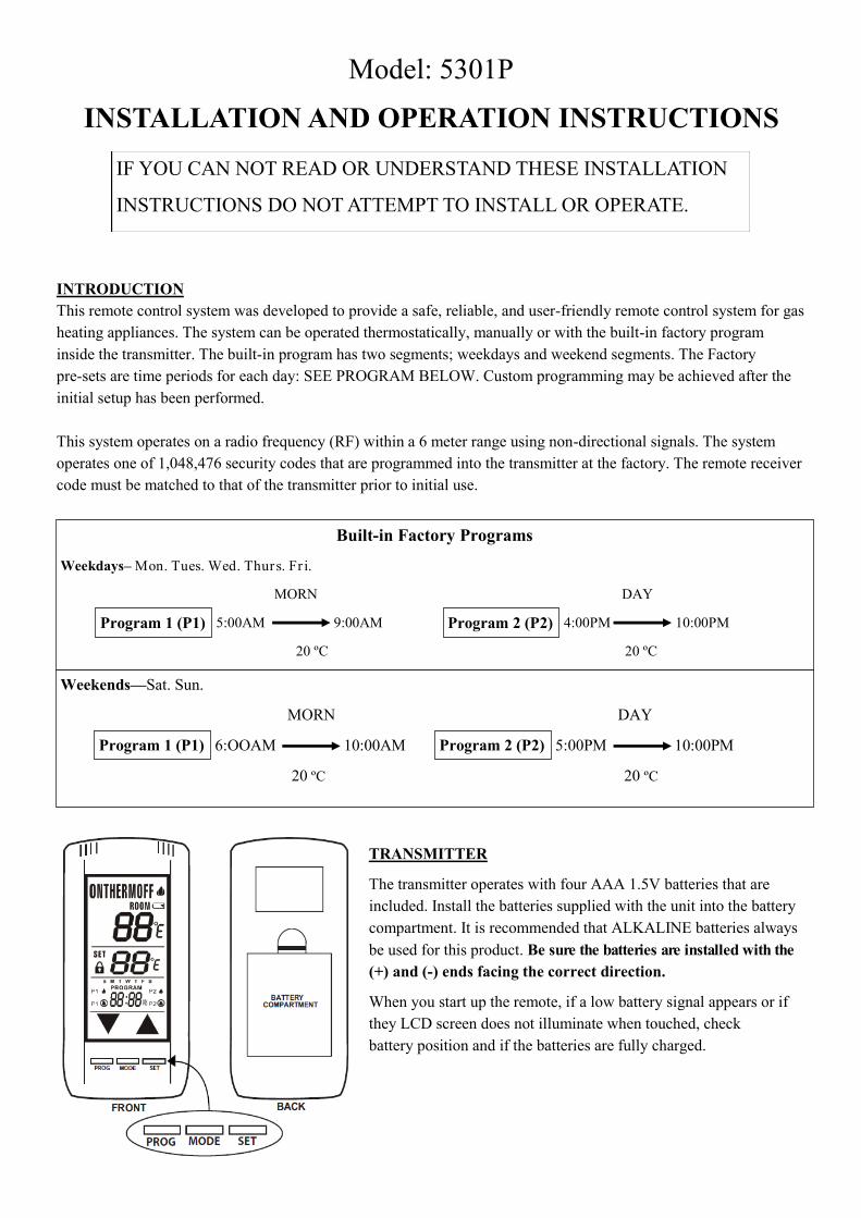
Model: 5301P
INSTALLATION AND OPERATION INSTRUCTIONS
INTRODUCTION
This remote control system was developed to provide a safe, reliable, and user-friendly remote control system for gas
heating appliances. The system can be operated thermostatically, manually or with the built-in factory program
inside the transmitter. The built-in program has two segments; weekdays and weekend segments. The Factory
pre-sets are time periods for each day: SEE PROGRAM BELOW. Custom programming may be achieved after the
initial setup has been performed.
This system operates on a radio frequency (RF) within a 6 meter range using non-directional signals. The system
operates one of 1,048,476 security codes that are programmed into the transmitter at the factory. The remote receiver
code must be matched to that of the transmitter prior to initial use.
TRANSMITTER
The transmitter operates with four AAA 1.5V batteries that are
included. Install the batteries supplied with the unit into the battery
compartment. It is recommended that ALKALINE batteries always
be used for this product. Be sure the batteries are installed with the
(+) and (-) ends facing the correct direction.
When you start up the remote, if a low battery signal appears or if
they LCD screen does not illuminate when touched, check
battery position and if the batteries are fully charged.
IF YOU CAN NOT READ OR UNDERSTAND THESE INSTALLATION
INSTRUCTIONS DO NOT ATTEMPT TO INSTALL OR OPERATE.
Built-in Factory Programs
Weekdays– Mon. Tues. Wed. Thurs. Fr i.
MORN DAY
5:00AM 9:00AM 4:00PM 10:00PM
20 ºC 20 ºC
Weekends—Sat. Sun.
MORN DAY
6:OOAM 10:00AM 5:00PM 10:00PM
20 ºC 20 ºC
Program 1 (P1) Program 2 (P2)
Program 2 (P2) Program 1 (P1)

KEY TOUCH SCREEN SETTINGS
1. MODE: Switches the appliance On/Ther mo/Off.
2. PROGRAM: Turn on and off the program function.
3. SET: Used in different functions to confirm settings.
4. UP/DOWN : Used to change the time, set temperature, and programming functions.
LCD: LIQUID COLOUR DISPLAY
1. BATTERY ICON : If battery power is low.
Replace Batteries in 2 - 4 weeks.
2. ROOM : Indicates the CURRENT room
temperature.
3. SET: Indicates desired room temperature for the THERMO operation.
4. FAHRENHEIT/CELSIUS: Indicates the degrees in Fahrenheit or
Celsius.
5. FLAME: Indicates burner /valve in operation.
6. MODE: Indicates operation mode of system.
7. UP/DOWN: These are used to adjust the Time, Set temperature, and
Program functions.
8. TIME/PROGRAM TIME: Indicates cur rent time or program time
setting when editing program settings.
9. LOCK ICON: Disables the transmitter when lock is visible on the LCD
screen.
10. PROGRAM ON/OFF: Indicates when Program 1 (P1) and Program 2 (P2) is on or off.
11. DAY of the WEEK - Indicates current day of week or the program segment when editing the program settings.
BASIC TRANSMITTER FUNCTIONS AND INITIAL SETUP
NOTE: Touch anywhere on the screen and the back light will light up for 5 seconds.
MODE FUNCTION
To select an operation mode, press the MODE button or touch the MODE SECTION at
the top of the LCD screen.
• ON: turns the appliance ON, the flame icon will appear .
• THERMO: sets the remote to Ther mostatic mode.
• OFF: turns the appliance OFF, the flame icon will disappear .
SETTING ºF/ ºC SCALE
The factory setting for temperature is ºF. To change this setting to ºC, press and hold the UP
button and the DOWN button on the transmitter at the same time.
Follow same procedure to change from ºC back to ºF.
NOTE: When changing between the ºF and ºC scales, the set temperature defaults to
the lowest temperature (45 ºF, or 6 ºC).
Review COMMUNICATION SAFETY under TRANSMITTER section.

SETTING THE CLOCK
• Press and hold the SET button, or touch the SET section on the touch screen, for five seconds. The hour section
should begin to flash. (See Fig. 1)
• Use the UP and DOWN touch buttons to select the hour, then press SET.
• The minutes will be flashing. Use the UP and DOWN buttons to select the minute. Then press SET. (See Fig. 2)
• The AM PM will be flashing. Use the UP and DOWN buttons to select one of them. Then press SET. (See Fig. 3)
One of the days of the week will be flashing above the clock. Select the correct day by pressing the UP and
DOWN touch buttons. Then press SET. Your time will automatically be accepted. (See Fig. 4)
WARNING
ELECTRONIC SPARK SYSTEM CHECK
Slide the third positioned button on the remote receiver to the ON position. The spark electrode should begin
sparking to the ignite pilot. After the pilot flame is lit, the main gas valve should open and the main gas flame
should ignite.
Slide the button OFF. The main gas flame and pilot flame should extinguish
Slide the button to REMOTE. Then press the ON button on the transmitter to turn the system on. The spark
electrode should begin sparking to ignite the pilot. After the pilot is lit, the main gas valve should open causing the
main gas flame to ignite.
RECEIVER
The remote receiver has a third position slide switch for selecting the mode of operation
ON/REMOTE/OFF
ON: will manually turn ON the appliance.
REMOTE: will allow use of handheld transmitter . If the system does not
respond to the transmitter when initially use, check the battery positions in the
remote. If that does not work, see the TRANSMITTER TO RECEIVER section
OFF: will disable the remote receiver .
It is recommended that the slide switch be placed in the OFF position if you will be
away from your home for an extended period of time.
This remote control system must be installed exactly as outlined in these instructions. Read all instructions
completely before attempting installation. Follow the instructions carefully during installation. Any
modifications on this remote control or any of its components will void the warranty and may pose a fire
hazard.
Do not connect any gas valve or electronic module directly to the 110-120VAC power. Consult gas appliance
manufacturer’s instructions and wiring schematics for correct placement of the wires. All electronic modules
are to be wired to manufacturers specifications.
TRANSMITTER TO RECIEVER
Each transmitter uses a unique security code. Press the LEARN button on the receiver to accept the transmitter
security code upon initial use or if batteries are replaced, or if a replacement transmitter is purchased from your
dealer or the factory. In order for the receiver to accept the transmitter security code, Slide the button on the receiver
to REMOTE position; the receiver will not LEARN if the slide switch is in the ON or OFF position. The LEARN
button is located on the front face of the receiver; inside the small hole labelled LEARN. Using a small screwdriver
or the end of a paperclip, gently press and release the black LEARN button inside the hole. When you release the
LEARN button the receiver will emit and audible “beep”. After the receiver emits the beep, press the transmitter
MODE button and release. The receiver will emit several beeps indicating that the transmitter’s code has been
accepted into the receiver.
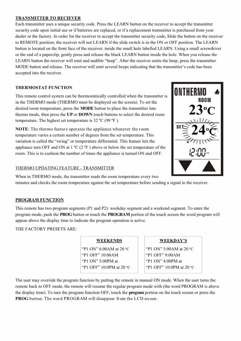
THERMOSTAT FUNCTION
This remote control system can be thermostatically controlled when the transmitter is
in the THERMO mode (THERMO must be displayed on the screen). To set the
desired room temperature, press the MODE button to place the transmitter into
thermo mode, then press the UP or DOWN touch buttons to select the desired room
temperature. The highest set temperature is 32 ºC (99 ºF ).
NOTE: The thermo feature operates the appliance whenever the room
temperature varies a certain number of degrees from the set temperature. This
variation is called the “swing” or temperature differential. This feature lets the
appliance turn OFF and ON at 1 ºC (2 ºF ) above or below the set temperature of the
room. This is to cushion the number of times the appliance is turned ON and OFF.
THERMO UPDATING FEATURE - TRANSMITTER
When in THERMO mode, the transmitter reads the room temperature every two
minutes and checks the room temperature against the set temperature before sending a signal to the receiver.
PROGRAM FUNCTION
This remote has two program segments (P1 and P2): weekday segment and a weekend segment. To enter the
program mode, push the PROG button or touch the PROGRAM portion of the touch screen the word program will
appear above the display time to indicate the program operation is active.
THE FACTORY PRESETS ARE:
The user may override the program function by putting the remote in manual ON mode. When the user turns the
remote back to OFF mode, the remote will resume the regular program mode with (the word PROGRAM is above
the display time). To turn the program function OFF, touch the program portion on the touch screen or press the
PROG button. The word PROGRAM will disappear from the LCD screen.
23ºC
24ºC
WEEKENDS
“P1 ON” 6:00AM at 20 ºC
“P1 OFF” 10:00AM
“P1 ON” 5:00PM at
“P1 OFF” 10:0PM at 20 ºC
WEEKDAY’S
“P1 ON” 5:00AM at 20 ºC
“P1 OFF” 9:00AM
“P1 ON” 4:00PM at
“P1 OFF” 10:0PM at 20 ºC
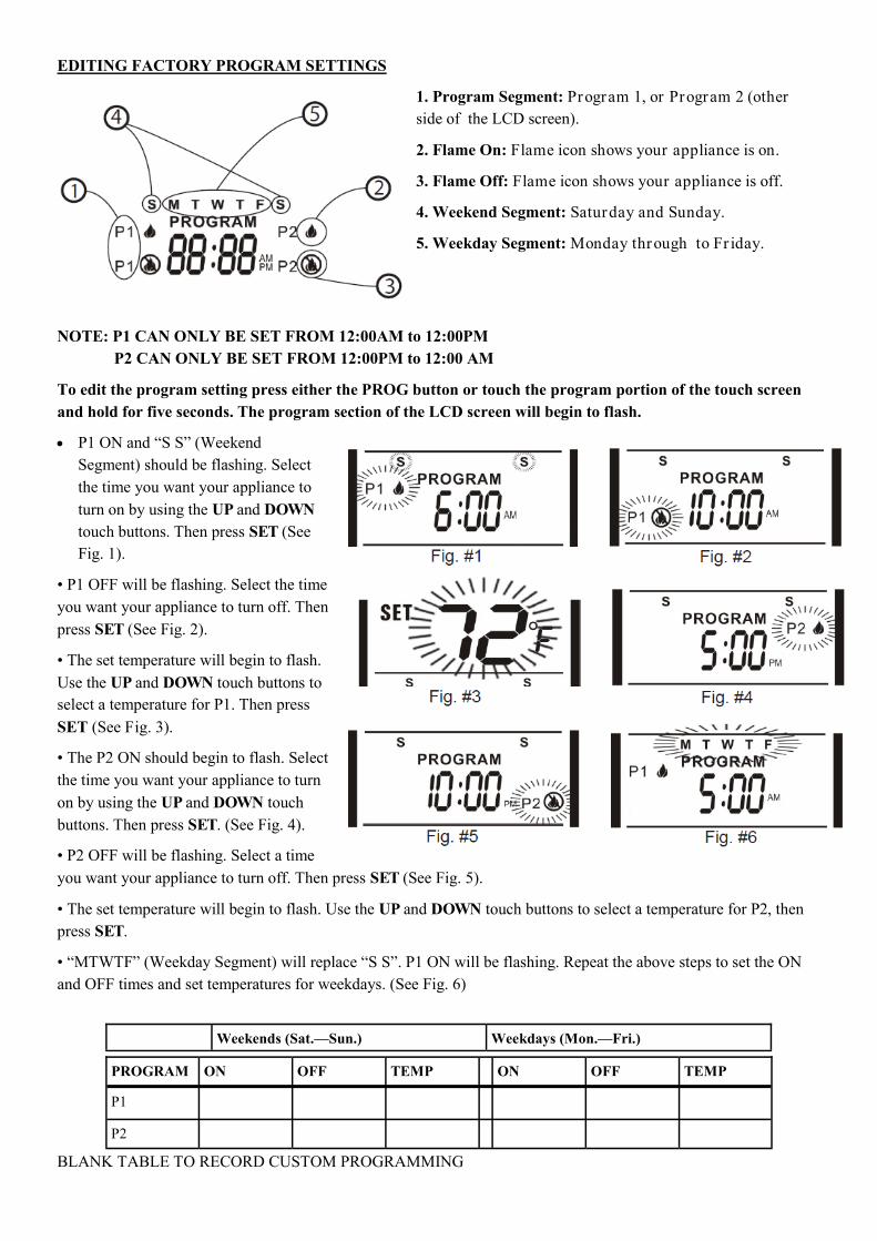
EDITING FACTORY PROGRAM SETTINGS
1. Program Segment: Program 1, or Program 2 (other
side of the LCD screen).
2. Flame On: Flame icon shows your appliance is on.
3. Flame Off: Flame icon shows your appliance is off.
4. Weekend Segment: Saturday and Sunday.
5. Weekday Segment: Monday through to Fr iday.
NOTE: P1 CAN ONLY BE SET FROM 12:00AM to 12:00PM
P2 CAN ONLY BE SET FROM 12:00PM to 12:00 AM
To edit the program setting press either the PROG button or touch the program portion of the touch screen
and hold for five seconds. The program section of the LCD screen will begin to flash.
P1 ON and “S S” (Weekend
Segment) should be flashing. Select
the time you want your appliance to
turn on by using the UP and DOWN
touch buttons. Then press SET (See
Fig. 1).
• P1 OFF will be flashing. Select the time
you want your appliance to turn off. Then
press SET (See Fig. 2).
• The set temperature will begin to flash.
Use the UP and DOWN touch buttons to
select a temperature for P1. Then press
SET (See Fig. 3).
• The P2 ON should begin to flash. Select
the time you want your appliance to turn
on by using the UP and DOWN touch
buttons. Then press SET. (See Fig. 4).
• P2 OFF will be flashing. Select a time
you want your appliance to turn off. Then press SET (See Fig. 5).
• The set temperature will begin to flash. Use the UP and DOWN touch buttons to select a temperature for P2, then
press SET.
• “MTWTF” (Weekday Segment) will replace “S S”. P1 ON will be flashing. Repeat the above steps to set the ON
and OFF times and set temperatures for weekdays. (See Fig. 6)
BLANK TABLE TO RECORD CUSTOM PROGRAMMING
PROGRAM ON OFF TEMP ON OFF TEMP
P1
P2
Weekends (Sat.—Sun.) Weekdays (Mon.—Fri.)
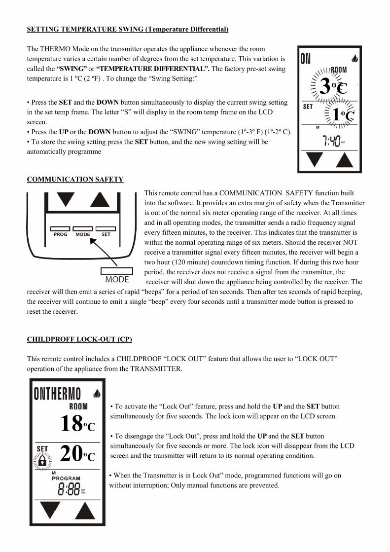
SETTING TEMPERATURE SWING (Temperature Differential)
The THERMO Mode on the transmitter operates the appliance whenever the room
temperature varies a certain number of degrees from the set temperature. This variation is
called the “SWING” or “TEMPERATURE DIFFERENTIAL”. The factory pre-set swing
temperature is 1 ºC (2 ºF) . To change the “Swing Setting:”
• Press the SET and the DOWN button simultaneously to display the current swing setting
in the set temp frame. The letter “S” will display in the room temp frame on the LCD
screen.
• Press the UP or the DOWN button to adjust the “SWING” temperature (1º-3º F) (1º-2º C).
• To store the swing setting press the SET button, and the new swing setting will be
automatically programme
COMMUNICATION SAFETY
This remote control has a COMMUNICATION SAFETY function built
into the software. It provides an extra margin of safety when the Transmitter
is out of the normal six meter operating range of the receiver. At all times
and in all operating modes, the transmitter sends a radio frequency signal
every fifteen minutes, to the receiver. This indicates that the transmitter is
within the normal operating range of six meters. Should the receiver NOT
receive a transmitter signal every fifteen minutes, the receiver will begin a
two hour (120 minute) countdown timing function. If during this two hour
period, the receiver does not receive a signal from the transmitter, the
receiver will shut down the appliance being controlled by the receiver. The
receiver will then emit a series of rapid “beeps” for a period of ten seconds. Then after ten seconds of rapid beeping,
the receiver will continue to emit a single “beep” every four seconds until a transmitter mode button is pressed to
reset the receiver.
CHILDPROFF LOCK-OUT (CP)
This remote control includes a CHILDPROOF “LOCK OUT” feature that allows the user to “LOCK OUT”
operation of the appliance from the TRANSMITTER.
• To activate the “Lock Out” feature, press and hold the UP and the SET button
simultaneously for five seconds. The lock icon will appear on the LCD screen.
• To disengage the “Lock Out”, press and hold the UP and the SET button
simultaneously for five seconds or more. The lock icon will disappear from the LCD
screen and the transmitter will return to its normal operating condition.
• When the Transmitter is in Lock Out” mode, programmed functions will go on
without interruption; Only manual functions are prevented.
3ºC
1ºC
18ºC
20ºC

TRANSMITTER WALL MOUNT
The transmitter can be placed on a wall using the mount provided:
Wood: Drill 1/8’’ pilot holes and install with screws provided.
Plaster/Wallboard: Drill 1/4’’ holes. Use a hammer to tap in the two plastic
anchors. Then install with the screws provided.
BATTERY LIFE
Life expectancy of the alkaline batteries in the transmitter and receiver should be at least
12 months. Check and replace all batteries:
Annually.
When operating range becomes reduced.
When transmissions are not received by the remote receiver.
If the remote receiver batteries measure less than 5.3 volts (all four batteries in combination).
If any of the hand held transmitter batteries measure less than 5.3 volts.
TROUBLESHOOTING
If you encounter problems with your fireplace system, the problem may be with either the fireplace itself or with the
remote. Review the fireplace manufacturer’s operation manual to make sure all connections are properly installed.
Then check the operation of the remote in the following manner:
Make sure all batteries are correctly installed in the transmitter and receiver. Also check that all of the batteries
are fully charged.
Check batteries in transmitter to make sure contacts are touching the correct position (+) and (-) ends of battery.
Bend metal contacts in for tighter fit.
Be sure that the receiver and transmitter are within the six to eight meter operating range.
Keep receiver from temperatures exceeding 55ºC. Battery life will be shortened from prolonged exposure to high
temperatures.
If receiver is installed in a tightly enclosed metal surrounding, the operating distance will be shortened.
Ensure that the hand-held transmitter and remote receiver are communicating properly (see TRANSMITTER TO
RECEIVER section).
FCC REQUIREMENTS
NOTE: THE MANUFACTURER IS NOT RESPONSIBLE FOR ANY RADIO OR TV
INTERFERENCE CAUSED BY UNAUTHORIZED MODIFICATIONS TO THE EQUIPMENT.
SUCH MODIFICATIONS COULD VOID THE USER’S AUTHORITY TO OPERATE THE
EQUIPMENT
FOR WARRANTY INFORMATION PLEASE CONTACT AURORA CLIMATE SYSTEMS;
1300 388 953


![Caliper Operation Instructions[1]](https://img.pdfslide.us/doc/110x75/577cc5701a28aba7119c6424/caliper-operation-instructions1.jpg)