Embed Size (px)
Citation preview

American Magnetics, Inc.P.O. Box 2509, 112 Flint Road, Oak Ridge, TN 37831-2509, Tel: 865-482-1056, Fax: 865-482-5472
Rev. 5; Issue: November 28, 2011
MODEL 4Q06125PS-430 INTEGRATED POWER
SUPPLY SYSTEM
INSTALLATION, OPERATION, AND
MAINTENANCE INSTRUCTIONS
EXCELLENCE IN MAGNETICS AND CRYOGENICS


Table of Contents
1 Table of Contents
Table of Contents............................................................................... iii
List of Figures .................................................................................... ix
List of Tables...................................................................................... xi
Foreword........................................................................................... xiii
Purpose and Scope ............................................................................. xiii
Contents of this Manual .................................................................... xiii
General Precautions........................................................................... xiv
Safety Summary................................................................................. xvi
Introduction......................................................................................... 1
1.1 Model 4Q06125PS-430 Integrated Power Supply System Features .. 11.1.1 Digitally-Controlled................................................................... 11.1.2 Superior Resolution and Stability ............................................ 11.1.3 Intuitive Human-Interface Design........................................... 11.1.4 Flexibility................................................................................... 21.1.5 Standard Remote Interfaces ..................................................... 21.1.6 Programmable Safety Features................................................ 21.1.7 Condition-Based Magnet Auto-Rampdown.............................. 21.1.8 Model 4Q06125PS-430 General Description............................ 31.1.9 Power Supply System Rack Front Panel Layout .............. 4
1.2 Model 430 Front Panel Layout............................................................. 5
1.3 Model 430 Rear Panel Layout ............................................................. 6
1.4 Power Supply Unit Front Panel Layout .............................................. 7
1.5 System Specifications @ 25°C ...................................................... 8
1.6 Operating Characteristics ................................................................... 91.6.1 Four-Quadrant Operation......................................................... 9
Installation......................................................................................... 11
2.1 Inspecting and Unpacking.................................................................. 11
2.2 Power Supply System Mounting ........................................................ 11
2.3 Power Requirements........................................................................... 122.3.1 Changing the Model 430 Programmer Operating Voltage ... 12
2.4 Collecting Necessary Information ...................................................... 12
2.5 System Interconnects.......................................................................... 132.5.1 High-Current 4-Quadrant Supply.......................................... 13
Rev. 5 iii
Table of Contents
2.6 Special Configurations.........................................................................16
2.7 Superconducting Magnets with No Persistent Switch ......................16
2.8 Short-Circuit or Resistive Load...........................................................17
2.9 Power-Up and Test Procedure ............................................................18
Operation............................................................................................21
3.1 System Power On/Off Sequence .........................................................213.1.1 Model 430 Programmer Power On/Off....................................213.1.2 Energizing Power Supply ........................................................22
3.2 Model 430 Programmer Default Display............................................223.2.1 Field / Current Display ............................................................233.2.2 Voltage Display ........................................................................243.2.3 Status Indicator .......................................................................243.2.4 Main Display ............................................................................25
3.3 Entering Numeric Values....................................................................25
3.4 Using Fine Adjust Knob to Adjust Numeric Values ..........................26
3.5 Entering Picklist Values......................................................................27
3.6 Single-key Commands / Menu.............................................................283.6.1 Persistent Switch Control Key ................................................293.6.2 Target Field Setpoint Key ......................................................313.6.3 Ramp / Pause Key ....................................................................313.6.4 Ramp To Zero Key....................................................................31
3.7 SHIFT-key Commands / Menus..........................................................323.7.1 Ramp Rate SHIFT-key ............................................................333.7.2 Voltage Limit SHIFT-key ........................................................363.7.3 Reset Quench SHIFT-key ........................................................373.7.4 Increment Field SHIFT-key ....................................................373.7.5 Field <> Current SHIFT-key...................................................383.7.6 Decrement Field SHIFT-key ...................................................383.7.7 Field Units SHIFT-key ............................................................383.7.8 Persistent Switch Heater Current SHIFT-key.......................393.7.9 Stability SHIFT-key.................................................................393.7.10 Vs <> Vm SHIFT-key...............................................................393.7.11 Volt Meter SHIFT-key .............................................................393.7.12 Fine Adjust SHIFT-key............................................................393.7.13 Persist. Switch Control SHIFT-key ........................................39
3.8 LED Indicators.....................................................................................403.8.1 Power-on Indicator...................................................................403.8.2 Magnet Status Indicators ........................................................403.8.3 SHIFT Indicator.......................................................................41
iv Rev. 5

Table of Contents
3.9 Setup Menu ......................................................................................... 413.9.1 Entering / Exiting Setup Menu .............................................. 413.9.2 Menu Navigation..................................................................... 42
3.10 Setup Submenu Descriptions ............................................................. 423.10.1 Supply Submenu ..................................................................... 433.10.2 Load Submenu......................................................................... 483.10.3 Misc Submenu ......................................................................... 593.10.4 Net Settings Submenu ............................................................ 683.10.5 Net Setup Submenu ................................................................ 70
3.11 Example Setup .................................................................................... 72
3.12 Ramping Functions ............................................................................ 743.12.1 Ramping States and Controls ................................................ 753.12.2 Manual Ramping..................................................................... 763.12.3 Automatic Ramping ................................................................ 763.12.4 Ramping to Zero ...................................................................... 773.12.5 Fine Adjust of Field / Current in Holding Mode.................... 77
3.13 Persistent Switch Control................................................................... 773.13.1 Procedure for Initial Heating of the Switch .......................... 783.13.2 Procedure for Entering Persistent Mode .............................. 783.13.3 Procedure for Exiting Persistent Mode ................................. 813.13.4 Toggling the State of the Persistent Switch Heater.............. 84
3.14 Ramping Functions Example ............................................................ 85
3.15 Quench Detection ............................................................................... 863.15.1 External Quench Detection..................................................... 873.15.2 Disabling Internal Quench Detection .................................... 88
3.16 External Rampdown .......................................................................... 883.16.1 External Rampdown while in Persistent Mode .................... 893.16.2 External Rampdown while not in Persistent Mode .............. 90
3.17 Summary of Operational Limits and Default Settings..................... 90
Remote Interface Reference ............................................................ 93
4.1 SCPI Command Summary ................................................................. 93
4.2 Programming Overview.................................................................... 1004.2.1 SCPI Language Introduction................................................ 1004.2.2 SCPI Status System.............................................................. 1004.2.3 Standard Event Register ...................................................... 1034.2.4 Command Handshaking ....................................................... 104
4.3 RS-232 Configuration ....................................................................... 1064.3.1 Serial Connector .................................................................... 1064.3.2 Termination Characters........................................................ 106
Rev. 5 v

Table of Contents
4.4 Ethernet Configuration .....................................................................1064.4.1 Ethernet Connector................................................................1074.4.2 Termination Characters ........................................................107
4.5 Command Reference ..........................................................................1084.5.1 System-Related Commands...................................................1084.5.2 Status System Commands.....................................................1094.5.3 SETUP Configuration Commands and Queries ...................1104.5.4 Protection Commands and Queries.......................................1154.5.5 Ramp Configuration Commands and Queries......................1204.5.6 Ramping State Commands and Queries...............................1244.5.7 Switch Heater Command and Query ....................................1254.5.8 Quench State Commands and Queries .................................1264.5.9 Rampdown State Queries ......................................................1264.5.10 Trigger Functions...................................................................128
4.6 Error Messages ..................................................................................1304.6.1 Command Errors....................................................................1304.6.2 Query Errors ..........................................................................1314.6.3 Execution Errors ....................................................................1324.6.4 Device Errors..........................................................................132
Service..............................................................................................135
5.1 System Component Maintenance .....................................................1355.1.1 Model 430 Programmer Routine Maintenance.....................1355.1.2 Model 4Q06125PS Power Supply Routine Maintenance .....135
5.2 Troubleshooting Hints .......................................................................1355.2.1 Electrostatic Discharge Precautions .....................................1355.2.2 The Model 430 does not appear to be energized...................1365.2.3 FAILURE TO LOAD message displayed after power-up ....1375.2.4 Power supply unstable - magnet voltage oscillates..............1385.2.5 The power supply system will not charge the magnet. ........1385.2.6 Cannot charge the magnet at the selected ramp rate..........1395.2.7 Cannot discharge the magnet at the selected ramp rate.....1395.2.8 Cannot charge the magnet to desired field...........................1395.2.9 Current in only one direction from 4-quadrant supply........1395.2.10 Cannot place the magnet in persistent mode. ......................1395.2.11 Cannot bring the magnet out of persistent mode.................1405.2.12 The magnet quenches for no apparent reason......................1405.2.13 Cannot lower the magnet field ..............................................1405.2.14 There is excessive LHe boil-off during operation. ................1415.2.15 Cannot display the magnetic field strength, only current...1415.2.16 Cannot use remote communications commands. .................1425.2.17 Magnet current drifts unacceptably while PSwitch cooling 1425.2.18 Model 430 appears to lock up when connecting to network 142
vi Rev. 5

Table of Contents
5.3 Additional Technical Support........................................................... 143
5.4 Return Authorization........................................................................ 143
Appendix.......................................................................................... 145
A.1 Magnet Station Connectors ......................................................... 145
A.2 LHe Level / Temp Connectors ...................................................... 146
A.3 Programmer Shunt Terminals ......................................................... 147
A.4 Program Out Connector ................................................................... 148
A.5 Quench I/O Connector....................................................................... 149A.5.1 External Quench Detection Input ........................................ 149A.5.2 External Rampdown Input ................................................... 150A.5.3 External Quench Detection Output ..................................... 151
A.6 Aux Inputs Connector ....................................................................... 152
A.7 Ethernet Connector ...................................................................... 153
A.8 RS-232 Connector.............................................................................. 153
A.9 Abbreviations and Acronyms used in this Manual ......................... 154
A.10 Model 430 Programmer Specifications ......................................... 158
A.11 Power Supply Details........................................................................ 161A.11.1 Model 4Q06125PS Electrical Specifications ........................ 161A.11.2 Model 4Q06125PS Dimensional Specifications ................... 164A.11.3 Four-Quadrant Characteristics ............................................ 165
A.12 Remote Computer Communication with the Model 430................ 166A.12.1 Communication via RS-232 .................................................. 166A.12.2 Communication via Ethernet ............................................... 169
A.13 Upgrading the Model 430 Firmware via FTP ................................. 172A.13.1 Hardware and Software Requirements................................ 172A.13.2 Preparation............................................................................ 173A.13.3 Procedure ............................................................................... 174
A.14 Upgrading the Model 430 Firmware via Flash Card Reader ......... 179A.14.1 Hardware and Software Requirements................................ 179A.14.2 Preparation............................................................................ 179A.14.3 Procedure ............................................................................... 180
A.15 Model 430 Remote Control Application ........................................... 183
A.16 Model 430IP Power Supply Programmer ........................................ 186
A.17 Persistent Switch Operation Flowchart .......................................... 189
Index ............................................................................................... 193
Rev. 5 vii

Table of Contents
viii Rev. 5

List of Figures
1 List of Figures
Figure 1-1 Typical Model 4Q06125PS-430 System Rack Layout............................ 4Figure 1-2 Model 4Q06125PS Front Panel............................................................... 7Figure 1-3 The Four Regions, or Quadrants, of System Operation. ....................... 9Figure 1-4 Four-Quadrant System with Resistive Shunt........................................ 9Figure 2-1 Typical Model 4Q06125PS-430 System Rack Interconnections.......... 14Figure 2-2 Model 4Q06125PS-430 System Interconnections ................................ 15Figure 3-1 Default Display. ..................................................................................... 23Figure 3-2 Numeric Keypad and Associated Keys ................................................. 25Figure 3-3 Menu Navigation Keys .......................................................................... 28Figure 3-4 Single Input Keys .................................................................................. 29Figure 3-5 SHIFT-Key Functions ........................................................................... 32Figure 3-6 Magnet Status LED Indicators. ............................................................ 40Figure 3-7 Setup Menu Structure........................................................................... 43Figure 3-8 Example Power Supply Outputs........................................................... 46Figure 3-9 Stability Setting vs. Magnet (with PSwitch) Inductance .................... 49Figure 3-10 Typical Power Supply Self-Limits ........................................................ 51Figure 3-11 Magnet Current Rating Set Within Supply Range.............................. 52Figure 3-12 Example Current Limit Setup .............................................................. 53Figure 3-13 Example Magnet Specification Sheet. .................................................. 73Figure 3-14 Ramping to Two Different Target Field/Current Settings. ................. 85Figure 4-1 The Model 430 Programmer Status System. ..................................... 101Figure 4-2 Asterisk Indicating Model 430 in Remote Mode ................................ 109Figure A-1 4Q06125PS Outline Drawing, Front and Rear Views ....................... 164Figure A-2 4Q06125PS Outline Drawing Top and Side Views............................ 165Figure A-3 Four-Quadrant Supply Output Characteristics................................. 166Figure A-4 http:// - IP Address or System Name Entry ....................................... 184Figure A-5 Initial Screen for Browser Access of the Model 430........................... 185Figure A-6 Model 430IP Front Panel .................................................................... 186Figure A-7 Browser Depiction of the Model 430................................................... 186Figure A-8 http:// - System Name Entry ............................................................... 187Figure A-9 Initial Screen for Browser Access of the Model 430IP....................... 187Figure A-10 Browser Control of the Model 430IP .................................................. 188Figure A-11 Persistent Switch Operation Flowchart, Page 1 ................................ 189Figure A-12 Persistent Switch Operation Flowchart, Page 2 ................................ 190Figure A-13 Persistent Switch Operation Flowchart, Page 3 ................................ 191
Rev. 5 ix

List of Figures
x Rev. 5

List of Tables
1 List of Tables
Table 1-1 Model 430 Front Panel Description ........................................................ 5Table 1-2 Model 430 Resistive Shunt Version Rear Panel Description ................ 6Table 1-3 Power Supply Front Panel Controls and Indicators .............................. 7Table 3-1 Description of Status Indicators ........................................................... 24Table 3-2 Select Supply picklist values and associated parameters. .................. 45Table 3-3 V-V Mode Input Range Picklist Values ................................................ 48Table 3-4 Maximum Recommended Stability Setting Changes ......................... 50Table 3-5 Example Setup Configuration............................................................... 74Table 3-6 Ramp modes and descriptions............................................................... 76Table 3-7 Summary of Model 430 Programmer Limits and Defaults ................. 91Table 4-1 Bit Definitions for the Status Byte Register ...................................... 102Table 4-2 Bit Definitions for the Standard Event Register ............................... 104Table 4-3 Return Values and Meanings for SUPPly:TYPE? Query.................. 111Table 4-4 Return Values and Meanings for SUPPly:MODE? Query.................. 112Table 4-5 Return Values and Meanings for STATE? Query............................... 125Table 4-6 Model 430 Programmer Trigger Function Bit Definitions ................ 128Table 5-1 V-V Mode Input Range Picklist Values .............................................. 137Table A-1 Magnet Station Connectors Pin Definitions....................................... 145Table A-2 LHe Level / Temp Connectors Pin Definitions................................... 146Table A-3 Program Out Connector Pin Definitions ............................................ 148Table A-4 Quench I/O Connector Pin Definitions ............................................... 149Table A-5 Aux Inputs Connector Pin Definitions ............................................... 152Table A-6 Ethernet RJ-45 Connector Pin Definitions ........................................ 153Table A-7 RS-232 Connector Pin Definitions ...................................................... 153Table A-8 PC (DB9)-to-Model 430 RS-232 Cable Connections........................... 154Table A-9 Abbreviations and Acronyms .............................................................. 154Table A-10 Model 430 Programmer Specifications @ 25°C ................................. 158Table A-11 Model 4Q06125PS Electrical Specifications....................................... 161
Rev. 5 xi

List of Tables
xii Rev. 5
Foreword
Purpose and Scope
This manual contains the operation and maintenance instructions for the American Magnetics, Inc. Model 4Q06125PS-430 Power Supply System. The user is encouraged to contact an authorized AMI Technical Support Representative for information regarding specific configurations not explicitly covered in this manual.
Contents of this Manual
Introduction introduces the reader to the functions and characteristics of the Model 430 Power Supply Programmer and the Power Supply System. It provides illustrations of the front and rear panel layouts as well as documenting the performance specifications. Additional information is provided in the form of system circuit diagrams.
Installation describes how the Model 430 Power Supply Programmer is unpacked and installed in conjunction with ancillary equipment in typical superconducting magnet systems. Block-level diagrams document the interconnects for various system configurations.
Operation describes how the Model 430 Programmer is used to control a superconducting magnet. All Model 430 Programmer displays and controls are documented. The ramping functions, persistent switch heater controls, and the quench detect features are also presented.
Remote Interface Reference documents all remote commands and queries available through the Model 430 Programmer RS-232 and Ethernet interfaces. A quick-reference summary of commands is provided as well as a detailed description of each.
Service provides guidelines to assist the user in troubleshooting possible system and Model 430 Programmer malfunctions. Information for contacting AMI Technical Support personnel is also provided.
Appendix provides additional details and/or procedures in the following areas:
1. Model 430 Programmer rear panel connectors.
2. Individual power supply unit specifications
Rev. 5 xiii
ForewordGeneral Precautions
3. Establishing RS-232 or Ethernet communications with the Model 430.
4. Model 430 firmware upgrade.
5. Abbreviations and acronyms used in this manual.
6. Persistent switch operation (flow diagram).
General Precautions
Cryogen Safety
The two most common cryogenic liquids used in superconducting magnet systems are nitrogen and helium. Both of these cryogens are extremely cold at atmospheric pressure (−321°F and −452°F, respectively). The following paragraphs outline safe handling precautions for these liquids.
Personnel handling cryogenic liquids should be thoroughly instructed and trained as to the nature of the liquids. Training is essential to minimize accidental spilling. Due to the low temperature of these materials, a cryogen spilled on many objects or surfaces may damage the surface or cause the object to shatter, often in an explosive manner.
Inert gases released into a confined or inadequately ventilated space can displace sufficient oxygen to make the local atmosphere incapable of sustaining life. Liquefied gases are potentially extreme suffocation hazards since a small amount of liquid will vaporize and yield a very large volume of oxygen-displacing gas. Always ensure the location where the cryogen is used is well ventilated. Breathing air with insufficient oxygen content may cause unconsciousness without warning. If a space is suspect, purge the space completely with air and test before entry. If this is not possible, wear a forced-air respirator and enter only with a co-worker standing by wearing a forced-air respirator.
Cryogenic liquids, due to their extremely low temperatures, will also burn the skin in a similar manner as would hot liquids. Never permit cryogenic liquids to come into contact with the skin or allow liquid nitrogen to soak clothing. Serious burns may result from careless handling. Never touch uninsulated pipes or vessels containing cryogenic liquids. Flesh will stick to extremely cold materials. Even nonmetallic materials are dangerous to touch at low temperatures. The vapors expelled during the venting process are sufficiently cold to burn flesh or freeze optic tissues. Insulated gloves should be used to prevent frost-bite when operating valves on cryogenic tanks. Be cautious with valves on cryogenic systems; the temperature extremes they are typically subjected to cause seals to fail frequently.
xiv Rev. 5
ForewordGeneral Precautions
In the event a person is burned by a cryogen or material cooled to cryogenic temperatures, the following first aid treatment should be given pending the arrival and treatment of a physician or other medical care worker:
1. If any cryogenic liquid contacts the skin or eyes, immediately flush the affected area gently with tepid water (102°F − 105°F, 38.9°C − 40.5°C) and then apply cold compresses.
2. Do not apply heat. Loosen any clothing that may restrict circulation. Apply a sterile protective dressing to the affected area.
3. If the skin is blistered or there is any chance that the eyes have been affected, get the patient immediately to a physician for treatment.
Containers of cryogenic liquids are self pressurizing (as the liquid boils off, vapor pressure increases). Hoses or lines used to transfer these liquids should never be sealed at both ends (i.e. by closing valves at both ends).
When pouring cryogenic liquids from one container to another, the receiving container should be cooled gradually to prevent damage by thermal shock. The liquid should be poured slowly to avoid spattering due to rapid boil off. The receiving vessel should be vented during the transfer.
Introduction of a substance at or near room temperature into a cryogenic liquid should be done with great caution. There may be a violent gas boil-off and a considerable amount of splashing as a result of this rapid boiling. There is also a chance that the material may crack or catastrophically fail due to forces caused by large differences in thermal contraction of different regions of the material. Personnel engaged in this type of activity should be instructed concerning this hazard and should always wear a full face shield and protective clothing. If severe spraying or splashing could occur, safety glasses or chemical goggles along with body length protective aprons will provide additional protection.
The properties of many materials at extremely low temperatures may be quite different from the properties that these same materials exhibit at room temperatures. Exercise extreme care when handling materials cooled to cryogenic temperatures until the properties of these materials under these conditions are known.
Metals to be used for use in cryogenic equipment application must posses sufficient physical properties at these low temperatures. Since ordinary carbon steels, and to somewhat a lesser extent, alloy steels, lose much of their ductility at low temperatures, they are considered unsatisfactory and sometimes unsafe for these applications. The austenitic Ni-Cr alloys exhibit good ductility at these low temperatures and the most widely used
Rev. 5 xv
ForewordSafety Summary
is 18-8 stainless steel. Copper, Monel®, brass and aluminum are also considered satisfactory materials for cryogenic service.
Magnet Quenches
When an energized superconducting magnet transitions from superconducting state to normal state, the magnet converts magnetic energy to thermal energy thereby rapidly converting the liquid helium to a vapor. When this phase transformation occurs, pressures can build rapidly in the cryostat due to the fact that one part of liquid helium will generate 782 parts of gaseous helium at STP (standard temperature and pressure). The cryostat must be designed to allow the generated vapor to rapidly and safely vent to an area of lower pressure. Cryostats are designed with pressure relief valves of sufficient capacity so as to limit the pressure transients within the container in order to prevent damage to the vessel. Operating a superconducting magnet in a cryostat without properly sized relief mechanisms or disabled relief mechanism is unsafe for the operator as well as for the equipment. If there is any doubt as to the sufficiency of the pressure relief system, contact the manufacturer of the magnet and cryostat for assistance.
Safety Summary
Superconducting magnet systems are complex systems with the potential to seriously injure personnel or equipment if not operated according to procedures. The use of cryogenic liquids in these systems is only one factor to consider in safe and proper magnet system operation. Proper use of safety mechanisms (pressure relief valves, rupture disks, etc.) included in the cryostat and top plate assembly are necessary. Furthermore, an understanding of the physics of the magnet system is needed to allow the operator to properly control the large amounts of energy stored in the magnetic field of the superconducting coil. The Model 430 Programmer has been designed with safety interlocks to assist the operator in safe operation, but these designed-in features cannot replace an operator’s understanding of the system to ensure the system is operated in a safe and deliberate manner.
Recommended Safety Equipment
• First Aid kit
• Fire extinguisher rated for class C fires
• Cryogenic gloves
• Face shield
• Signs to indicate that there are potentially damaging magnetic fields in the area and that cryogens are in use in the area.
xvi Rev. 5

ForewordSafety Summary
Safety Legend
Instruction manual symbol: the product is marked with this symbol when it is necessary for you to refer to the instruction manual in order to protect against damage to the product or personal injury.
Hazardous voltage symbol.
Alternating Current (Refer to IEC 417, No. 5032).
Off (Supply) (Refer to IEC 417, No. 5008).
On (Supply) (Refer to IEC 417, No. 5007).
Warning
The Warning sign denotes a hazard. It calls attention to a procedure or practice, which if not correctly adhered to, could result in personal injury. Do not proceed beyond a Warning sign until the indicated conditions are fully understood and met.
Caution
The Caution sign denotes a hazard. It calls attention to an operating procedure or practice, which if not adhered to, could cause damage or destruction of a part or all of the product. Do not proceed beyond a Caution sign until the indicated conditions are fully understood and met.
OI
Rev. 5 xvii

ForewordSafety Summary
xviii Rev. 5

1 Introduction
1.1 Model 4Q06125PS-430 Integrated Power Supply System Fea-tures
The AMI Model 4Q06125PS-430 Power Supply System is a sophisticated digitally-controlled power supply which allows an operator to manage a superconducting magnet system with unprecedented accuracy and ease of use. Integral components of the system include a Model 430 Programmer and Model 4Q06125PS Power Supply. The AMI Model 4Q06125PS-430 Power Supply System provides for a degree of flexibility and accuracy previously unavailable in an economical commercial product.
1.1.1 Digitally-Controlled
The Power Supply System is controlled by a microcomputer-based control-ler which controls all analog data conversion, display/keypad functions, communications I/O, generation of analog programming signals for the external power supply, and control law computations. The Power Supply System incorporates digital signal processing (DSP) functions that provide for accurate control, low drift, and flexibility of use.
1.1.2 Superior Resolution and Stability
The Model 430 Power Supply Programmer incorporates high-resolution converters to translate signals between the analog and digital domains. Precision instrumentation techniques and potentiometer-free designs are employed throughout the Model 430 Programmer to ensure accurate sig-nal translation for a wide range of conditions. The magnet current is sam-pled at 24-bit resolution in hardware and is software-programmable to 15-digits resolution. All pause and hold functions are performed in the digital domain which provides for excellent stability and drift of the programmed magnetic field.
1.1.3 Intuitive Human-Interface Design
The Power Supply System was designed to simplify the interface where possible. All functions were analyzed and subsequently programmed so that the most commonly used functions are addressed with the least number of keystrokes. The menus are also presented in a logical fashion so that the operation of the Power Supply System is intuitive to the user.
The provision of a velocity-sensitive rotary encoder on the front panel also allows the operator to fine-adjust many of the operating parameters of the magnet system.
Rev. 5 1
IntroductionFeatures
1.1.4 Flexibility
The Model 4Q06125PS-430 system is configured as a four-quadrant power supply system which is able to both supply and remove electrical energy from the superconducting magnet system. The Power Supply System was engineered to be compatible with most magnet systems.
1.1.5 Standard Remote Interfaces
The Power Supply System provides an RS-232 serial port as well as an Ethernet port as standard features. All settings can be controlled via the remote interfaces and the front panel can be remotely locked to prevent accidental operation. The Power Supply System also provides trigger functions for data collection and/or logging during operation.
1.1.6 Programmable Safety Features
The Power Supply System is designed to be operated from the front panel of the Programmer or remotely with operational parameters which must not be exceeded for the given conditions of the system. Once set, should an operator inadvertently attempt to take the magnet system to an excessive magnetic field strength or charge at an excessive voltage, the Programmer will not accept the parameter and will alert the operator that a value was rejected because it was outside the user-defined limits.
In addition, each setup parameter can be individually selected for locking. A user-defined password is required to lock or unlock settings. This allows an administrator to set and password protect any critical parameters that should not be changed by the operator. Then the administrator can be confident that an operator will not subsequently change any of these critical parameters, and yet will be free to change any non-critical (unlocked) parameters.
1.1.7 Condition-Based Magnet Auto-Rampdown
The Power Supply System can be connected to an AMI Model 13x Liquid Helium Level Instrument to allow automatic rampdown of the magnet (even in persistent mode) should the liquid helium (LHe) level drop to a preset level. This feature ensures the magnet will be protected and not experience a quench should the LHe level reach an unsafe level for magnet operation. A single cable is required to use this feature and is covered in more detail in section A.5.2 on page 150 of the Appendix. Contact AMI for more information.
In addition to low LHe level, this input to the Power Supply System can be used with other instrumentation as well. Other uses for this input include faults from a cryocooler, temperature instrumentation, etc.
2 Rev. 5
IntroductionGeneral Description
1.1.8 Model 4Q06125PS-430 General Description
A Model 430 Power Supply Programmer and Model 4Q06125PS Power Supply are configured to make up the system designated as 4Q06125PS-430. The Model 4Q06125PS is a 750 Watt, ±6 Volt, ±125 ampere, 4-quadrant, voltage and current stabilized DC supply. The power supply is remotely controlled by the Model 430 Power Supply Programmer.
The Model 4Q06125PS-430 is a true 4-quadrant voltage and current power supply capable of both sourcing and sinking1 power smoothly through zero to provide true ±voltage and ±current. It is ideal for controlling inductive loads such as large magnets or motors.
The power supply is controlled by a ±10 Vdc remote analog signal supplied by the Model 430 Programmer and applied to the power supply analog input. Programming and control of the current loop (composed of the magnet, power supply, and Model 430 Programmer shunt), is provided by a Model 430 ramp-generated current reference with parameters as set by the user in the Model 430. The Model 430 compares the measured current (via the shunt) with the current reference to provide precise closed-loop control of the actual current.
The power supply is operated in voltage-voltage2 programming mode, with the Model 430 Programmer output scaled to operate the power supply over its available voltage output range. The Programmer signal will continually adjust the power supply output voltage to automatically regulate the power supply current; precise linear power supply current control will result as long as the system voltage and current demand do not exceed the power supply rating or load limiting parameters.
1. The power supply is operating as a source if the current direction and voltage polar-
ity are the same (i.e., the situation that would exist when supplying a resistive load).
If the voltage polarity and current direction are opposite, the supply is operating as
a sink and energy is being absorbed or returned to the “ac-line”.
2. Voltage reference controlling voltage output.
Rev. 5 3
IntroductionSystem Rack
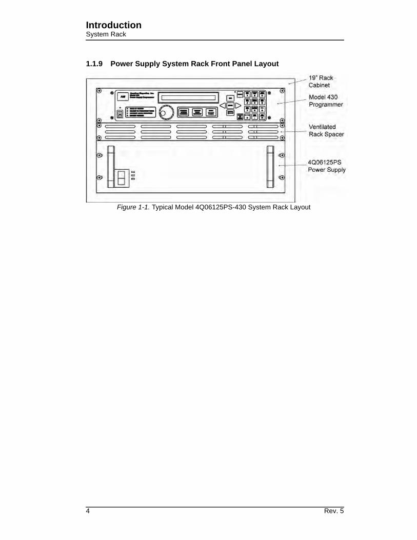
1.1.9 Power Supply System Rack Front Panel Layout
Figure 1-1. Typical Model 4Q06125PS-430 System Rack Layout
4 Rev. 5
IntroductionModel 430 Front Panel
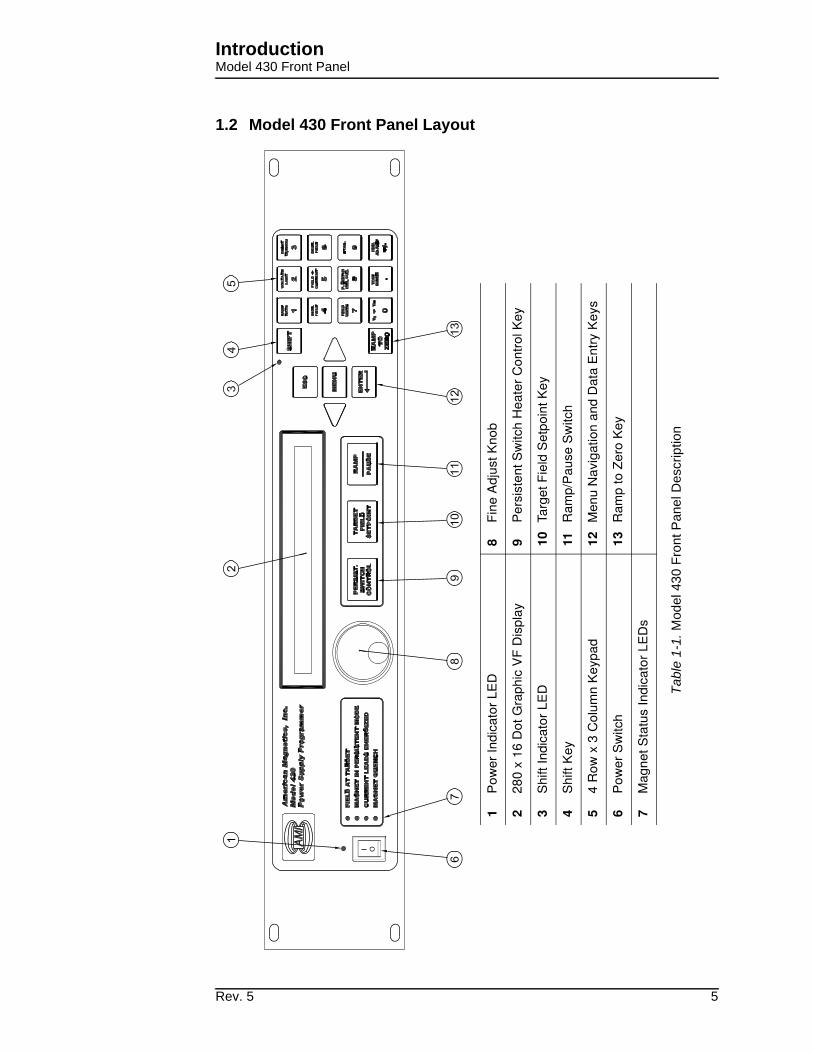
1.2 Model 430 Front Panel Layout
1P
ow
er
Ind
ica
tor
LE
D8
Fin
e A
dju
st K
no
b
22
80
x 1
6 D
ot
Gra
ph
ic V
F D
isp
lay
9P
ers
iste
nt
Sw
itch
He
ate
r C
on
tro
l Ke
y
3S
hift
In
dic
ato
r L
ED
10
Targ
et
Fie
ld S
etp
oin
t K
ey
4S
hift
Key
11
Ra
mp
/Pa
use
Sw
itch
54
Ro
w x
3 C
olu
mn
Ke
ypa
d12
Men
u N
avi
gat
ion
and
Dat
a E
ntry
Key
s
6P
ow
er
Sw
itch
13
Ra
mp
to
Ze
ro K
ey
7M
ag
ne
t S
tatu
s In
dic
ato
r L
ED
s
Tabl
e 1-
1. M
od
el 43
0 F
ront
Pa
ne
l D
escrip
tio
n
Rev. 5 5

IntroductionModel 430 Rear Panel Layout
1.3 Model 430 Rear Panel Layout
Tabl
e 1-
2. M
od
el 43
0 R
esis
tive
Sh
un
t V
ers
ion
Rea
r P
an
el D
escri
ption
6 Rev. 5
IntroductionPower Supply Front Panel Layout
43233
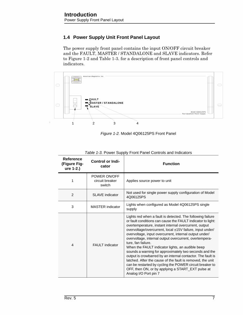
1.4 Power Supply Unit Front Panel Layout
The power supply front panel contains the input ON/OFF circuit breaker and the FAULT, MASTER / STANDALONE and SLAVE indicators. Refer to Figure 1-2 and Table 1-3. for a description of front panel controls and indicators.
Figure 1-2. Model 4Q06125PS Front Panel
Table 1-3. Power Supply Front Panel Controls and Indicators
Reference (Figure Fig-
ure 1-2.)
Control or Indi-cator
Function
1POWER ON/OFF
circuit breaker switch
Applies source power to unit
2 SLAVE indicatorNot used for single power supply configuration of Model 4Q06125PS
3 MASTER indicatorLights when configured as Model 4Q06125PS single supply
4 FAULT indicator
Lights red when a fault is detected. The following failure or fault conditions can cause the FAULT indicator to light: overtemperature, instant internal overcurrent, output overvoltage/overcurrent, local ±15V failure, input under/overvoltage, input overcurrent, internal output under/overvoltage, internal output overcurrent, overtempera-ture, fan failure. When the FAULT indicator lights, an audible beep sounds a warning for approximately two seconds and the output is crowbarred by an internal contactor. The fault is latched. After the cause of the fault is removed, the unit can be restarted by cycling the POWER circuit breaker to OFF, then ON, or by applying a START_EXT pulse at Analog I/O Port pin 7
SLAVEMASTER / STANDALONEFAULT
American Magnetics, Inc.
AMI
Model 4Q06125PSFour-Quadrant Power Supply
AMI
1 2 3 4
Rev. 5 7

IntroductionPower Supply Front Panel Layout
1.5 System Specifications @ 25°C
Magnet Current Control
Range: −125 to +125 A
Programming Accuracy: 50 mA
Stability: 25 mA after 20 min. at desired current
Minimum Ramp Rate: 100 μA/min
Maximum Ramp Rate: 10 A/sec
Output Voltage
Range: −6 to +6 Vdc
Measurement Resolution: 10 mV
Load Inductance
Range: 0.5 to 100 H
Primary Power Requirements
Range: 200 - 230 Vac ±10%
50 / 60 Hz, 2000 VA
Physical
Dimensionsa:
a. H = height; W = width; D = depth
12.5” H x 21” W x 24.5” D
(318 mm H x 533 mm W x 622 mm D)
Approximate Weight: 90 lbm (40 kg)
Terminal Torque Limit: 48 lbf-in (5.4 N-m)
Environmental Limits
Ambient Temperature: 0 °C to 40 °C (32 °F to 104 °F)
Relative Humidity: 0 to 95%; non-condensing
8 Rev. 5

IntroductionOperating Characteristics
1.6 Operating Characteristics
The Model 430 Programmer has been designed to perform with var-ious power supplies to allow the user the greatest degree of system flexibility. The power supply and Programmer combination are cate-gorized by one of three forms: sin-gle-quadrant, dual-quadrant, and four-quadrant. For sake of clarity, the term quadrant is defined as one of four areas of a cartesian coordinate system where the abscissa is current and the ordi-nate is voltage. Refer to Figure 1-3.
1.6.1 Four-Quadrant Operation
The four-quadrant magnet power supply system illustrated in Figure 1-4 offers the most control of all the modes of operation. Efficiency is increased and reversible magnetic field profiles are attainable without discontinuities in the current. All of the voltage and current control is performed electronically so that system reliability is improved. Disadvantages of the four-quadrant system include somewhat increased cost of the power supply over single or dual-quadrant power supplies, and added complexity in protecting the power supply in the event of AC power loss or magnet quenching. Nonetheless, modern four-quadrant power supplies which include integral output protection against AC power loss and magnet quenching are available at reasonable prices.
20
-20
200-200
V
I
Positive CurrentFlow Direction
Positive VoltagePolarity
Positive CurrentFlow Direction
Negative VoltagePolarity
Negative CurrentFlow Direction
Positive VoltagePolarity
Negative CurrentFlow Direction
Negative VoltagePolarity
12
43
Figure 1-3. The Four Regions, or Quadrants, of System Operation.
MagnetCoil(s)
PersistentSwitch
(optional)
Misc. Line Losses
Model 420Shunt
VFour-QuadrantPower Supply
Current
Figure 1-4. Four-Quadrant System with Resistive Shunt
430
Rev. 5 9

IntroductionOperating Characteristics
10 Rev. 5
2 Installation
Warning
Before energizing the equipment, the earth ground of the power receptacle must be verified to be at earth potential and able to carry the rated current of the power circuit. Using extension cords should be avoided; however, if one must be used, ensure the ground conductor is intact and capable of carrying the rated current.
In the event that the ground path becomes less than sufficient to carry the rated current of the power circuit, the equipment should be disconnected from power, labeled as unsafe, and removed from place of operation.
Do not operate this equipment in the presence of flammable gases. Doing so could result in a life-threatening explosion.
Do not modify this equipment in any way. If component replacement is required, return the equipment to AMI facilities as described in the Troubleshooting section of this manual.
If used in a manner not specified in this manual, the protection provided by the design, manufacture and documentation of the system may be impaired.
2.1 Inspecting and Unpacking
Carefully remove the equipment, interconnecting cabling, and documentation CD (and/or printed material) from the shipping carton, and remove all packaging material.
Note
If there is any shipping damage, save all packing material and contact the shipping representative to file a damage claim. Do not return to AMI unless prior authorization has been received.
2.2 Power Supply System Mounting
If the system is to be used on a table top, place the equipment on a flat, secure surface.
Rev. 5 11

InstallationPower Requirements
2.3 Power Requirements
Warning
The power requirement for each system component is marked on the rear panel of the unit adjacent to the power entry connectors. Be sure the power supply system is configured for the proper power source prior to plugging in the line cords. Do not fail to connect the input ground terminal securely to an external earth ground.
Ensure the front panel power switches are in the OFF (O) position. Verify that the power supply components are configured for the proper operating voltage by referring to the equipment rear panels. If the operating voltage is correct, plug the line cords into power entry connectors, and into the appropriate power receptacles.
2.3.1 Changing the Model 430 Programmer Operating Voltage
Warning
The following procedure is to be performed only when the Model 430 Programmer is completely de-energized by removing the power-cord from the power receptacle. Failure to do so could result in personnel coming in contact with high voltages capable of producing life-threatening electrical shock.
Note
The voltage selector switch is labeled “115” for nominal line voltages from 100 to 115 VAC. The switch is labeled “230” for nominal line voltages of 200 to 230 VAC.
If the Model 430 Programmer operating voltage must be changed, ensure the instrument is de-energized by disconnecting the power cord from the power source. Remove the Model 430 Programmer cover by removing the four screws on both sides of the cover and the four screws from the corners of the cover on the back panel; slide the voltage selector switch on the main printed circuit board to the proper voltage. Replace the Model 430 Programmer cover.
2.4 Collecting Necessary Information
In order to properly configure the Model 430 Programmer, specific system information is required. Such parameters as the magnet electrical properties, type of power supply, persistent switch heating current requirements, and voltage and current constraints of the magnet are entered into the Model 430 Programmer once and nonvolatile memory will retain the data even after power is removed from the instrument. An
12 Rev. 5

InstallationPower Requirements
example of the data to be entered and how it is entered is described in section 3.11 on page 72.
If the Model 430 Programmer was purchased as part of a magnet system, essential data will have already been entered at the AMI factory and a configuration sheet will have been provided detailing the settings.
2.5 System Interconnects
If the Model 430 Programmer was purchased as part of a magnet system, all applicable system components and wiring harnesses will have been shipped with the system.
The diagrams that follow will assist in system equipment setup.
Caution
The wiring between the power supply and the magnet current leads must be of sufficient size to carry the full rated current of the power supply. Typically, for short runs (less than 25 ft, or 7.6 m), 2 AWG wire is sufficient for 125 A current, and 2/0 AWG wire is best for 250 A current.
Note that an AMI Model 13x Liquid Helium Level Instrument is shown as a possible component of each integrated system. The main instrumentation cable connecting the magnet support stand to one of the Model 430 Programmer MAGNET STATION connectors contains all the instrumentation and control connections needed to control and monitor the magnet. The signals in this cable which are required to monitor LHe level and temperatures are also presented at the LHe Level / Temp Connectors. Refer to the Appendix for pin-outs of these and other connectors.
2.5.1 High-Current 4-Quadrant Supply
For the four-quadrant power supply system, the components include the Model 430 Programmer, the 4Q06125PS power supply, and associated interconnection cabling. Figure 2-2 on page 15 illustrates the
Rev. 5 13

InstallationPower Requirements
interconnects for the AMI Model 4Q06125PS-430 Power Supply system. Refer to Figure 2-1 for a physical view of the interconnects.
Refer to Figure 2-2 on page 15. Ensure the cabling is connected in the following manner1:
a. Connect the power supply OUTPUT terminal (1) to the positive magnet current lead (2).
Note
The use of locking hardware is recommended for all high-current connections.
Caution
Do not overtighten the hardware on the interconnection terminals (refer to specifications table on page 8 for torque limits). Overtightening can result in damage to the terminals.
b. Connect the negative magnet current lead (3) to the positive (+) resistive shunt terminal (4) on the back of the Model 430 Programmer.
1. Some connections take more than one cable - read the complete procedure before
beginning.
Figure 2-1. Typical Model 4Q06125PS-430 System Rack Interconnections
14 Rev. 5

InstallationPower Requirements
Mo
del 430 R
ear
Pan
el
45
7A
MI M
od
el 4Q
06125 S
up
ply
Figu
re 2
-2. M
ode
l 4
Q0
612
5P
S-4
30
Syste
m I
nte
rcon
nection
s
!
Su
pe
rco
nd
uc
tin
g
Mag
net
1
2
3
6
8
9
LIN
E V
OLT
AG
E,
1A
MA
X
CO
NT
RO
LLE
R O
UT
PU
TC
OM
MU
NIC
AT
ION
S
50-6
0 H
z (
SE
L.
SW
. IN
SID
E)
J2
AM
ER
ICA
N M
AG
NE
TIC
S,
INC
.
OA
K R
IDG
E,
TN
U
.S.A
.
INP
UT
PO
WE
R
RS
-232
J8S
11ON
90-1
32 V
AC
180-2
64 V
AC
SE
NS
OR
J1
!
!
AM
I M
od
el 13x R
ear
Pan
el
10
11
12
13
14
Rev. 5 15
InstallationMagnets w/o Persistent Switch
c. Connect the negative (−) resistive shunt terminal (5) on the back of the Model 430 Programmer to the power supply COMMON terminal (6).
d. Connect the DB15 cable from the PROGRAM OUT connector (12) on the back of the Model 430 Programmer to the ANALOG I/O connector (7) on the rear of the power supply.
e. Install an instrumentation cable between the magnet support stand top plate connector (8) and one of the MAGNET STATION connectors (14) on the rear of the Model 430 Programmer.
f. Optional: Install an instrumentation cable between one of the LHe LEVEL / TEMP (13) connectors on the rear of the Model 430 Programmer and the Model 13x Liquid Helium Level Instrument and/or temperature instrument (9). Refer to section A.2 on page 146.
g. Optional: Install an instrumentation cable between the QUENCH I/O connector (11) on the rear of the Model 430 Programmer and Aux connector J2 (10) on the rear panel of the Model 13x Liquid Helium Level Instrument. Refer to section A.5.2 on page 150.
h. Connect each device line cord from the respective device to the appropriate power receptacle.
i. Remote communications via Ethernet and/or RS-232 can be accomplished by connecting suitable cabling to the Model 430 Programmer rear panel ETHERNET and/or RS-232 connectors.
2.6 Special Configurations
The Model 430 Programmer has been designed for optimal operation with a superconducting magnet (i.e. a very low resistance, high inductance load) with a persistent switch. The Model 430 Programmer is capable of controlling current to other loads; however, some modification to the Model 430 Programmer settings and/or connections must usually be made. Two commonly encountered configurations are: 1) superconducting magnets without a persistent switch, and 2) operation on a short-circuit or low resistance load.
2.7 Superconducting Magnets with No Persistent Switch
An external stabilizing resistor for superconducting magnets without a persistent switch is no longer required1. However, these systems do
16 Rev. 5

InstallationOperation on a Short-Circuit
require a specific Model 430 Programmer stability setting based on the magnet inductance as follows:
For magnet inductance <= 100 Henries (H):Stability Setting = (100 - H)
For magnet inductance > 100 Henries:Stability Setting = 0
2.8 Short-Circuit or Resistive Load
If operating with a short-circuit as a load without the presence of a superconducting magnet, the Model 430 Programmer must be manually configured for stability. Normally, when the persistent switch heater is deactivated, the Model 430 Programmer sees essentially a short-circuit load since the persistent switch shunts all current flow away from any connected magnet. Therefore, one method of operating a short-circuit is to indicate that a persistent switch is present, with the persistent switch heater deactivated.
The preferred method is to indicate that a persistent switch is not present (see section 3.10.2.6 on page 54) and adjust the stability setting (see section 3.10.2.1 on page 48) to control the load. A stability setting of 100% will always allow control of a short-circuit as the load, regardless of the state of the persistent switch heater.
If the resistance of the load is increased, the stability setting must be decreased to improve the transient response of the system. If the current appears to lag, then decrease the stability setting until the system is responsive. If the current appears to oscillate, increase the stability setting until the oscillations are damped.
Note
If you have purchased a superconducting magnet with the Model 430 Programmer, AMI will normally provide a recommended stability setting for optimal operation of the magnet system. If you operate the Model 430 Programmer with a different load, be sure to restore the stability setting to the recommended value when the superconducting magnet is reconnected.
The stability setting is essentially manual control of the gain of an integrator present in the control logic of the Model 430 Programmer. Increasing the stability setting decreases the gain of the integrator.
1. Effective with Model 430 firmware version 1.62.
Rev. 5 17

InstallationPower-Up Procedure
2.9 Power-Up and Test Procedure
It is important to verify that the magnet system has been properly connected before the superconducting magnet is energized. This is especially recommended if the system is to be controlled via a computer since this setup will allow software debugging without the potential for damage to the magnet. The following procedures will assist the user in the verifying key system components.
1. Using the appropriate diagram from section 2.5 as a guide, verify all system components are connected as shown. If there is any doubt as to the correct connection of a component, contact an AMI Technical Support Representative. The user may be required to properly make a few connections between the various system components which were disconnected to facilitate packing and shipping.
2. Temporarily place a short across the magnet current terminals. Often this is most easily accomplished by unfastening the heavy cables from the magnet current leads and fastening them together.1 This will allow rudimentary power supply checks without energizing the superconducting magnet.
3. Energize the Model 430 Programmer by placing the power switch in the I (ON) position.
4. When prompted by the Model 430 Programmer, energize the power supply and press ENTER on the Model 430 Programmer.
Warning
All power supply parameters, both hardware and software, have been set at the AMI factory. Power supply control, with the exception of powering ON and OFF, is done by way of the AMI Model 430 Power Supply Programmer. No field adjustments or reconfiguration of the power supply should be attempted in the field unless specifically described in this document or recommended in writing by an AMI Technical Support Representative.
5. Enter a stability setting of 100%. Refer to sections 3.3 on page 25 and 3.7.9 on page 39.
6. Verify the various setup menu values for the system (with the exception of the stability setting, which is to be temporarily left at 100%). If the power supply system was purchased with an AMI
1. If the system shipped with CamLoc quick-disconnect connectors, they may be
quickly disconnected from the magnet leads and connected together.
18 Rev. 5

InstallationPower-Up Procedure
magnet, AMI has preset the setup menu values for proper operation. See sections 3.3, 3.5, 3.9 and 3.10 for more discussion of the setup menu values and their entry into the Model 430 Programmer.
7. Set the Model 430 Programmer to display current (rather than field). Refer to sections 3.2.1 and 3.7.5.
8. Set the ramp rate to 1 A/sec. Refer to sections 3.3 on page 25 and 3.7.1 on page 33.
9. Set the target current to 10 A. Refer to sections 3.3 on page 25 and 3.6.2 on page 31.
10. If a Persistent Switch is installed, set the PSw P/S Ramp Rate to 10 A/sec. Refer to paragraph 3.10.2.11 on page 56
11. Initiate ramping to the target current by pressing the RAMP / PAUSE key (status indicator changes from P to ).
12. The system should ramp to 10 A in approximately 10 seconds. Verify this is the case (if a PSwitch is installed and in the cooled state, ramp time to 10 A should be slightly less than 2 seconds).
13. When the target current is achieved, the FIELD AT TARGET LED will be illuminated. The display should show “+10.00 A -” indicating that the Model 430 Programmer is in the holding mode at the target current value (+10.00 A).
Note
There may be a discrepancy between the current shown on the power supply display1 and the current displayed on the Model 430 Programmer. The current measurement system incorporated in the Model 430 is more accurate than the power supply shunt.
14. Verify that the power supply output current display indicates that a total of approximately 10 A is being supplied to the load (which is only the cabling in this case).
15. Set the target current to the Current Limit value. Refer to section 3.10.2.4 on page 52 to determine the Current Limit value. After the new target current value is entered, the Model 430 Programmer should ramp automatically to the new setting.
16. When the new target current value is reached, the power supply current display (if provided) should also indicate the new value.
1. Not all power supplies have a local current readout.
Rev. 5 19

InstallationPower-Up Procedure
17. Press the RAMP TO ZERO key to ramp the system to zero current.
18. Perform remote control software checkout as required.
19. Turn off the power supply.
20. Reset the stability setting and ramp rate of the Model 430 Programmer to an appropriate value for the magnet to be operated. Then turn off the Model 430.
21. Remove the short from the power supply leads and connect the leads to the magnet current leads of the magnet.
After successful completion of this test, the system is ready for operation with a superconducting magnet. Refer to the ramping function example presented in section 3.14 on page 85 for a discussion of the various available ramping methods.
20 Rev. 5

3 Operation
This section describes the operation of the Model 430 Programmer. Every menu and submenu item is illustrated and described in detail. An example setup of the Model 430 Programmer is presented in section 3.11 on page 72. An example ramping operation is presented in section 3.14 on page 85.
3.1 System Power On/Off Sequence
The Model 430 Programmer should always be energized before the power supply that it is controlling. The Model 430 Programmer is designed to prompt the user in order to ensure the power supply is energized at the proper time. The Model 430 Programmer should always be de-energized after the power supply is shut down.
3.1.1 Model 430 Programmer Power On/Off
Place the Model 430 Programmer power switch in the ON position. After the Model 430 Programmer is powered on and fully initialized (about 20 seconds), the following display will appear:
After this screen is displayed, the power supply can be powered up (See “Energizing Power Supply” on page 22.) followed by pressing the ENTER key on the Model 430 Programmer. This brings up the default display1.
Note
If turned off, the Model 430 Programmer must remain unpowered for at least 5 seconds before it is powered back on. If not, there may be an initialization error, in which case the following screen will be displayed.
1. Refer to section 3.2 on page 22.
+0.00 A - Turn on power supply+0.00 Vs Press ENTER to continue
AMI Model 430 ProgrammerFAILURE TO LOAD.
Rev. 5 21

OperationEnergizing Power Supply System Components
If this occurs, turn the Model 430 Programmer off, wait 15 seconds or more, and power the Model 430 Programmer back on.
When powering the system off, first turn off the power supply controlled by the Model 430 Programmer followed by the Model 430 Programmer. The controller will then ensure the load sees no abnormal power transients as the power supply is turning off.
3.1.2 Energizing Power Supply
Warning
Do not change power supply jumpers, dip-switches, or other factory settings. If not rack-mounted, always position power supply for convenience in disconnecting the power cords.
Place the power supply switch in the ON position. No local (front panel) adjustments or connections are required since the power supply control mode and other parameters have been factory-configured for control by the AMI Model 430 Power Supply Programmer.
When powering the system off, turn OFF the power supply before powering off the Model 430 Programmer.
3.2 Model 430 Programmer Default Display
The default display is illustrated in the figure below. It is displayed whenever no menus are being accessed and no errors are being indicated. The default display can be thought of as being logically divided into four
22 Rev. 5

OperationDefault Display : Field / Current
display areas — the Field / Current Display area, the Voltage Display area, the Status Indicator area and the Main Display area.
3.2.1 Field / Current Display
The field / current display indicates either the field strength or current1. This is always displayed in the upper left corner of the display (see Figure 3-1), regardless of what else is being displayed on the Model 430 Programmer display. The parameter displayed (field or current) is toggled by pressing SHIFT followed by FIELD <> CURRENT. Thus, if field strength is being displayed, pressing SHIFT followed by FIELD <> CURRENT will cause the current to be displayed; conversely, if current is being displayed, pressing SHIFT followed by FIELD <> CURRENT will cause the field strength to be displayed. Operating current is always displayed in amperes (A). Operating field strength may be displayed in kilogauss (kG) or tesla (T) if a coil constant has been specified in the setup2. If field strength is being displayed, the units (kG or T) in which it is displayed can be toggled by pressing SHIFT followed by FIELD UNITS.
Note
Note that the displayed field strength is not directly measured, but rather is calculated by multiplying the coil constant entered in the setup menu by the measured current flow of the Model 430 power supply system.
1. The value is always displayed in current (A) when an installed persistent switch is in
the cooled state since the value represents power supply current only, independent
of magnet current/field.
2. Refer to section 3.10.2.2 on page 50.
+50.00 A — Status: Holding +0.50 Vs PSwitch Heater: ON
+50.00 A — -10 0Vm +10 +1.50 Vs |''''|''''|''''|'''''|
Field / Current Display.
Default display showing ramp mode and persistent switch heater status:
Default display showing voltmeter:
Figure 3-1. Default Display.
Voltage Display.Status Indicator. Main Display.
Rev. 5 23

OperationDefault Display : Voltage
3.2.2 Voltage Display
The voltage display indicates either the voltage across the magnet (Vm) or the power supply output voltage (Vs). This is always displayed in the lower left corner of the display (see Figure 3-1), regardless of what else is being displayed on the Model 430 Programmer display. The parameter displayed (magnet voltage or power supply voltage) is toggled by pressing SHIFT followed by Vs <> Vm. Vm indicates the voltage measured across the terminals of the connected superconducting magnet. In order for the Model 430 Programmer to measure the magnet voltage, the magnet voltage taps must be connected to the Model 430. Normally this is done through the Magnet Station Cable provided by AMI (if the whole magnet system is provided by AMI). Vs indicates the Model 430 Programmer-controlled power supply output voltage.
Note
Note that the displayed power supply voltage (Vs) is not directly measured, but rather is calculated based on power supply control voltage being provided by the Model 430 Programmer and the power supply input control voltage and output voltage values entered in the setup menu.
3.2.3 Status Indicator
The status indicator indicates the Model 430 Programmer operating status. It is always visible (except during a quench condition) and is displayed just to the right of the field / current display (see Figure 3-1). The status indicator may be one of six symbols indicating one of the seven states shown in Table 3-1.
If the ramping mode character is blank, then a quench condition exists and the red MAGNET QUENCH indicator in the status section of the front panel will be
illuminated. See section 3.12 on page 74 for a detailed discussion of the meaning of the ramping modes (Paused, Ramping Up, Ramping Down and Holding).
Table 3-1. Description of Status Indicators
P Paused
Ramping Up
Ramping Down
– Holding
Heating Persistent Switch
Cooling Persistent Switch
V Voltage Limit
24 Rev. 5
OperationDefault Display : Main
3.2.4 Main Display
The default main display (the rightmost portion of the display – see Figure 3-1) shows either a voltmeter indicating magnet voltage or ramp mode and persistent switch heater state. Ramp mode is displayed on the top line of the main display; it will be one of eight states, as shown in Table 3-6 on page 76. Persistent switch heater state is displayed on the bottom line of the main display. If the Model 430 Programmer has been setup for use with a persistent switch, it will indicate either ON or OFF for the persistent switch heater state; otherwise, it will display “No PSwitch Installed.”
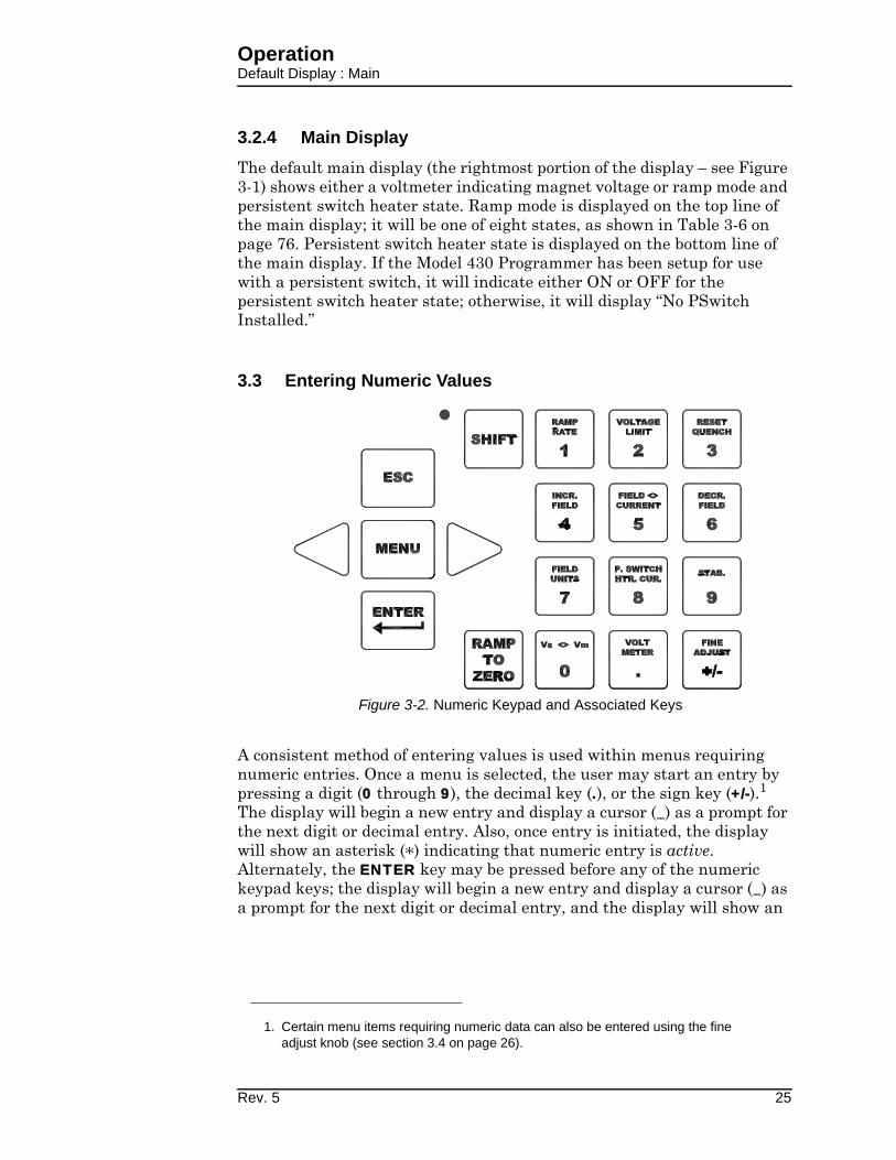
3.3 Entering Numeric Values
A consistent method of entering values is used within menus requiring numeric entries. Once a menu is selected, the user may start an entry by pressing a digit (0 through 9), the decimal key (.), or the sign key (+/-).1 The display will begin a new entry and display a cursor (_) as a prompt for the next digit or decimal entry. Also, once entry is initiated, the display will show an asterisk (*) indicating that numeric entry is active. Alternately, the ENTER key may be pressed before any of the numeric keypad keys; the display will begin a new entry and display a cursor (_) as a prompt for the next digit or decimal entry, and the display will show an
1. Certain menu items requiring numeric data can also be entered using the fine
adjust knob (see section 3.4 on page 26).
Figure 3-2. Numeric Keypad and Associated Keys
Rev. 5 25

OperationFine Adjust Knob Operation
asterisk (*) indicating that numeric entry is active. An example of a numeric entry in progress (numeric entry active) is illustrated below:
Once the numeric value has been entered, press the ENTER key to accept the numeric value. Values are not applied to the operation of the Model 430 Programmer until the ENTER key is pressed and the asterisk disappears from the display. Attempts to set a parameter to a value outside of the valid range are ignored, and if attempted the Model 430 Programmer will beep once indicating an error and revert to the previous setting.
If the ESC key is pressed while numeric entry is active and digits have been entered, the entered digits will be cleared and the cursor will remain for reentry of a new desired value. If the ESC key is pressed with no entered digits on the display, the setting will revert to the previous value and numeric entry will be made inactive. Thus, if digits have been entered, the first time ESC is pressed, the entered digits are cleared, but numeric entry remains active; if ESC is then pressed again (with no entered digits displayed), the setting reverts to its previous value and numeric entry is made inactive. Note that if the ESC key is pressed when numeric entry is not active, the current submenu will be exited and the next higher level submenu will be entered.
3.4 Using Fine Adjust Knob to Adjust Numeric Values
For menu items requiring entry of a numeric value, the value may alternatively be adjusted with the front panel fine adjust knob. These menu items include:
• Target Field Setpoint (in holding mode or while ramping)
• Voltage Limit
• Ramp Rate (if there is no PSwitch or if PSwitch is fully heated). Disallowed during switch heating/cooling transition.
• Custom Supply Menu (Min Output Voltage, Max Output Voltage, Min Output Current, Max Output Current)
• Stability
• Coil Constant
• Current Limit
• Magnet Current Rating
+50.00 A - Target Current (A)*+0.50 Vs +74_
26 Rev. 5
OperationEntering Picklist Values
• PSw P/S Ramp Rate if PSwitch is fully cooled. Disallowed during switch heating/cooling transition.
• PSwitch Current
• PSwitch Heated Time
• PSwitch Cooled Time
• PSwitch Cooling Gain
• Quench Rate
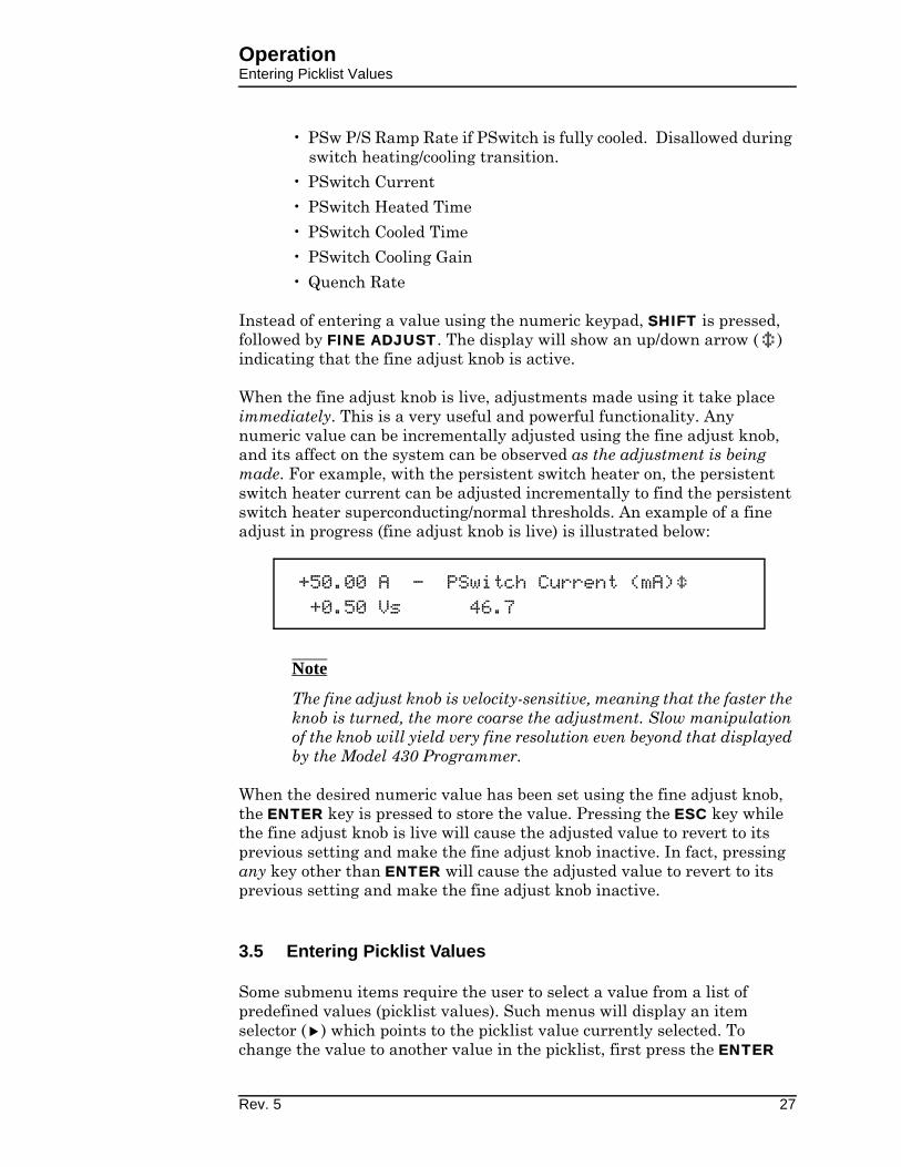
Instead of entering a value using the numeric keypad, SHIFT is pressed, followed by FINE ADJUST. The display will show an up/down arrow ( ) indicating that the fine adjust knob is active.
When the fine adjust knob is live, adjustments made using it take place immediately. This is a very useful and powerful functionality. Any numeric value can be incrementally adjusted using the fine adjust knob, and its affect on the system can be observed as the adjustment is being made. For example, with the persistent switch heater on, the persistent switch heater current can be adjusted incrementally to find the persistent switch heater superconducting/normal thresholds. An example of a fine adjust in progress (fine adjust knob is live) is illustrated below:
Note
The fine adjust knob is velocity-sensitive, meaning that the faster the knob is turned, the more coarse the adjustment. Slow manipulation of the knob will yield very fine resolution even beyond that displayed by the Model 430 Programmer.
When the desired numeric value has been set using the fine adjust knob, the ENTER key is pressed to store the value. Pressing the ESC key while the fine adjust knob is live will cause the adjusted value to revert to its previous setting and make the fine adjust knob inactive. In fact, pressing any key other than ENTER will cause the adjusted value to revert to its previous setting and make the fine adjust knob inactive.
3.5 Entering Picklist Values
Some submenu items require the user to select a value from a list of predefined values (picklist values). Such menus will display an item selector ( ) which points to the picklist value currently selected. To change the value to another value in the picklist, first press the ENTER
+50.00 A - PSwitch Current (mA)+0.50 Vs 46.7
Rev. 5 27

OperationSingle-key Commands
key; the display will show an asterisk (*) indicating that picklist entry is active.
While picklist entry is active, the left and right keypad arrows (to the left and right of the MENU key) move the item selector between the different picklist values. Pressing the left keypad arrow moves the item selector one picklist value to the left and pressing the right keypad arrow moves the item selector one picklist value to the right. When the last picklist value is reached, and the right keypad arrow is pressed, the item selector will move to the first picklist value. Likewise, when the item selector is pointing to the first picklist value, and the left keypad arrow is pressed, the item selector will move to the last picklist value. An example of a picklist entry in progress (picklist entry active) is illustrated below:
When the item selector is pointing at the desired picklist value, press the ENTER key to accept the picklist value. Values are not applied to the operation of the Model 430 Programmer until the ENTER key is pressed and the asterisk disappears from the display.
If the ESC key is pressed while picklist entry is active, the setting will revert to the previous value and picklist entry will be made inactive. Note that if the ESC key is pressed when numeric entry is not active, the current submenu will be exited and the next higher level submenu will be entered (if it exists).
3.6 Single-key Commands / Menu
All ramping controls (PERSIST. SWITCH CONTROL, TARGET FIELD SETPOINT, RAMP / PAUSE and RAMP TO ZERO) are accessed with a single keystroke. See section 3.12 on page 74 for details of ramping controls. Below is a brief summary of the function of each of these keys.
Figure 3-3. Menu Navigation Keys
+50.00 A - Field Units*+0.50 Vs Kilogauss Tesla
28 Rev. 5
OperationSingle-key Commands : Persistent Switch Control
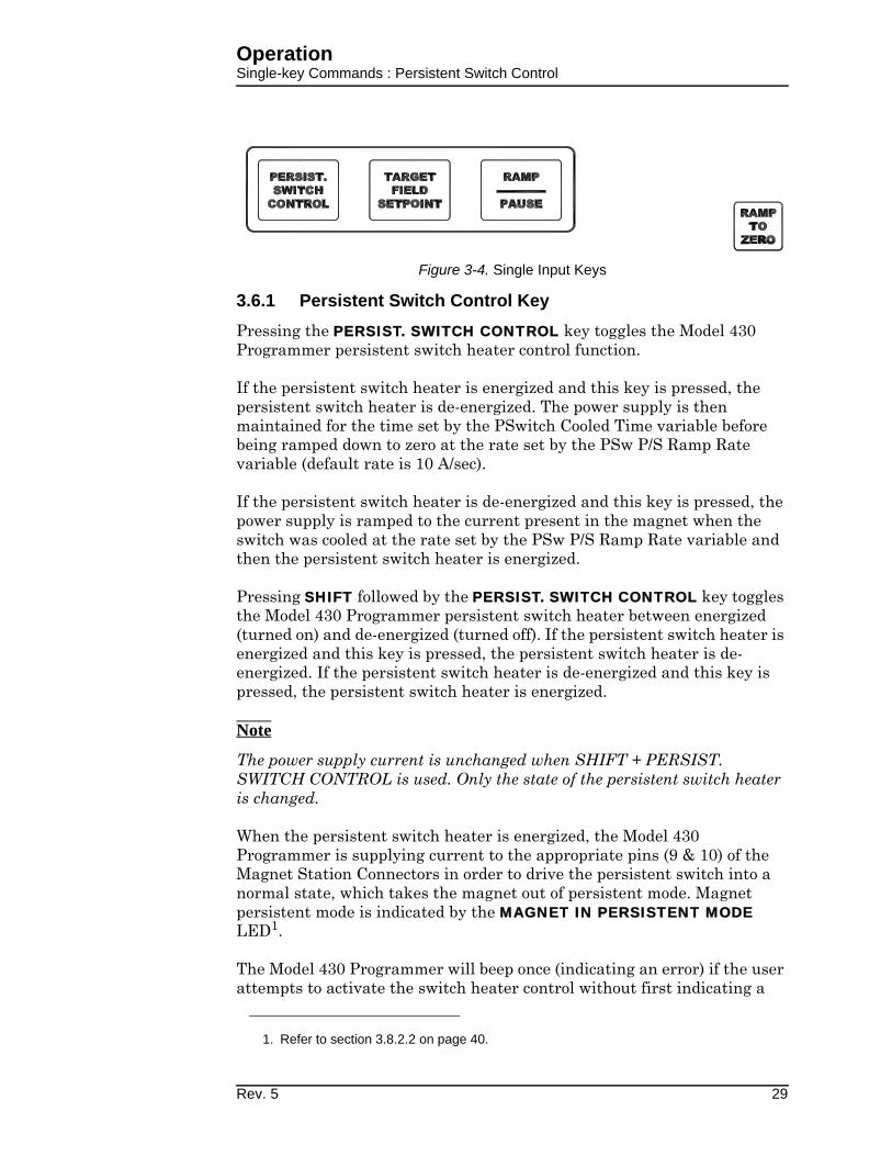
3.6.1 Persistent Switch Control Key
Pressing the PERSIST. SWITCH CONTROL key toggles the Model 430 Programmer persistent switch heater control function.
If the persistent switch heater is energized and this key is pressed, the persistent switch heater is de-energized. The power supply is then maintained for the time set by the PSwitch Cooled Time variable before being ramped down to zero at the rate set by the PSw P/S Ramp Rate variable (default rate is 10 A/sec).
If the persistent switch heater is de-energized and this key is pressed, the power supply is ramped to the current present in the magnet when the switch was cooled at the rate set by the PSw P/S Ramp Rate variable and then the persistent switch heater is energized.
Pressing SHIFT followed by the PERSIST. SWITCH CONTROL key toggles the Model 430 Programmer persistent switch heater between energized (turned on) and de-energized (turned off). If the persistent switch heater is energized and this key is pressed, the persistent switch heater is de-energized. If the persistent switch heater is de-energized and this key is pressed, the persistent switch heater is energized.
Note
The power supply current is unchanged when SHIFT + PERSIST. SWITCH CONTROL is used. Only the state of the persistent switch heater is changed.
When the persistent switch heater is energized, the Model 430 Programmer is supplying current to the appropriate pins (9 & 10) of the Magnet Station Connectors in order to drive the persistent switch into a normal state, which takes the magnet out of persistent mode. Magnet persistent mode is indicated by the MAGNET IN PERSISTENT MODE LED1.
The Model 430 Programmer will beep once (indicating an error) if the user attempts to activate the switch heater control without first indicating a
1. Refer to section 3.8.2.2 on page 40.
Figure 3-4. Single Input Keys
Rev. 5 29
OperationSingle-key Commands : Persistent Switch Control
persistent switch is installed in the Load submenu and specifying the switch heating current, heated time, and cooled time1.
The nominal switch heating current is listed on the magnet specification sheet, and may be entered in the Model 430 Programmer by accessing the Load submenu2. In addition to the heating current, the user must also specify a heated time, cooled time, PSw P/S Ramp Rate and cooling gain. The heated time allows the Model 430 Programmer to delay compensating the internal control logic until the magnet is guaranteed to be in the circuit. The heated time can be set from a minimum of 5 seconds to a maximum of 120 seconds within the Load submenu3. The default heating period of 20 seconds is adequate for the majority of persistent switches.
If the magnet appears unstable just after the switch heating period expires, increase the switch heated time to allow for complete heating. The cooled time allows the persistent switch sufficient time to be cooled to superconducting state before the current is changed in the magnet. The cooled time can be set from a minimum of 5 seconds to a maximum of 3600 seconds within the Load submenu4. The default cooling period of 20 seconds is adequate for the majority of wet persistent switches. Conduction cooled switches typically require longer time to transition from resistive to superconducting.
The default cooling gain of 0.0% may be adequate for the majority of wet persistent switches. However, this setting may result in some magnet drift during persistent switch cooling, especially with conduction cooled switches. Increasing the cooling gain adds control loop gain during the switch cooling cycle. Too little may result in magnet drift during switch cooling. Too much may result in power supply instability during switch cooling, which could potentially prevent the switch from cooling. Most systems requiring some cooling gain to control magnet drift will likely work with value set to 25%.
Note
During the period the switch is being heated or cooled, the Model 430 Programmer will not allow ramping functions to be executed and will beep once if the user attempts to initiate a ramping operation.
Refer to section 3.13 on page 77 for a complete description of magnet persistent switch control. A flowchart of the persistent switch control functions are located in the Appendix beginning on page 189.
1. Refer to section 3.10.2.6 on page 54, section 3.10.2.8 on page 55, section 3.10.2.9
on page 55, and section 3.10.2.10 on page 56.
2. Refer to section 3.10.2.8 on page 55.
3. Refer to section 3.10.2.9 on page 55.
4. Refer to section 3.10.2.10 on page 56.
30 Rev. 5

OperationSingle-key Commands : Target Field Setpoint
3.6.2 Target Field Setpoint Key
Pressing the TARGET FIELD SETPOINT key provides a menu for setting the target field/current. The target field/current is the field or current to which the Model 430 Programmer ramps the superconducting magnet when it is not paused. The target field/current may be set to the lesser of (1) the Magnet Current Rating, and (2) the Current Limit1 or equivalent field (per defined coil constant). The target field/current requires a sign since it defines a setpoint within the entire field/current range of the system (positive or negative).
When on the default display, pressing the SHIFT + TARGET FIELD SETPOINT keys will temporarily display the Magnet Current/Field for three seconds before reverting to the default display. The value displayed is as follows:
•When in driven mode, the present current/field will be displayed.
•When in persistent mode, the current/field will be displayed that was flowing in the magnet at the time persistent switch was cooled.
3.6.3 Ramp / Pause Key
Pressing the RAMP / PAUSE key toggles the Model 430 Programmer between the ramping mode and the paused mode. If the RAMP / PAUSE key is pressed while the Model 430 is ramping, the ramping is paused. If the RAMP / PAUSE key is pressed while the Model 430 is paused, the Model 430 continues ramping.
3.6.4 Ramp To Zero Key
Pressing the RAMP TO ZERO key causes the Model 430 Programmer to immediately begin ramping field/current up or down to zero field/current at the defined ramp rate(s). Ramping to zero may be interrupted at any time by pressing the RAMP / PAUSE key, which causes the Model 430 Programmer to enter the PAUSED mode and maintain the field/current present at the point it was paused.
1. Refer to section 3.10.2.4 on page 52.
+50.00 A - Target Field (kG)+0.50 Vs +50.000
+0.25 A P Magnet Current (A)+0.00 Vs +10.00 A
Rev. 5 31

OperationShift Key Commands
Note
If the RAMP TO ZERO function is PAUSED and then the RAMP / PAUSE button is pressed a second time, the Model 430 Programmer will begin ramping to the target field, not to zero. If it is desired to ramp to zero after the RAMP / PAUSE button is pressed, press the RAMP TO ZERO button again to continue ramping to zero from the paused state.
Note
If the magnet is persistent (persistent switch heater is not energized) when the RAMP TO ZERO key is pressed, the Model 430 Programmer ramps the power supply current to zero; the magnet current will remain constant since the magnet is in persistent mode.
3.7 SHIFT-key Commands / Menus
The most commonly used commands and menus (other than ramping controls) are accessed using the SHIFT key followed by a numeric keypad key. Use of the specific SHIFT-key commands and menus is described in sections specific to the functionality of that specific SHIFT-key. In general, a SHIFT-key command is executed or SHIFT-key menu is accessed by first pressing the SHIFT key (which turns on the SHIFT LED), and then pressing1 one of the keys of the numeric keypad (0 through 9, “.”, or “+/-”). The SHIFT-key command / menu for each key of the numeric keypad is shown in light blue text at the top of each key. To access the voltage limit
1. Note the SHIFT key and the following keypad key-press are sequential, not simulta-
neous.
Figure 3-5. SHIFT-Key Functions
32 Rev. 5

OperationShift Key Commands : Ramp Rate
menu, for example, press the SHIFT key, and then press the VOLTAGE LIMIT key (also the 2 key). Note that some of the SHIFT-key menus can also be accessed using the setup menu.
Pressing the ESC key or the SHIFT key a second time will clear the SHIFT function and return the keypad to it's numeric function.
3.7.1 Ramp Rate SHIFT-key
Use of the RAMP RATE SHIFT-key provides a menu for setting ramp rate(s). The ramp rate may be set1 within the range specified for the specific Model 430 Programmer configuration (refer to specifications on page 8). If field units are being used, then the ramp rate setting is displayed and set in units of kG/sec or T/sec). The allowable range is then defined by the setting of the coil constant and the allowable range of the ramp rate in terms of current as specified in the table on page 8. If the Ramp Segments value2 is greater than 1, then the menu also allows setting of the field or current range for which each ramp rate is to be used.
The Model 430 Programmer will ramp at the specified rate if the available compliance of the power supply is sufficient and the Voltage Limit is not exceeded. The Model 430 automatically decreases the ramp rate internally during operation if either the available compliance of the power supply is insufficient, or the Voltage Limit is active.
3.7.1.1 Ramp Rate SHIFT-key Example
An example (using a magnet with rated current of 60 A3) will illustrate the use of the ramp rate menus. The example assumes that the field/current units have been set to amperes. and the ramp segments value has been set to 3. Segmented magnet current ramping is chosen with rates as follows:
1. ±0.2 A/s from 0 to ±55 A2. ±0.1 A/s from ±55 to ±58 A3. ±0.05 A/s above ±58 A.
In the following discussion, the fine adjust knob4 can optionally be used for ramp rate adjustment if the persistent switch is heated (or if no persistent switch is installed). If the user attempts to edit ramp rate segments using the fine adjust knob while an installed switch is cooled, the Model 430 Programmer will produce one beep to indicate an error5. Similarly, if the switch is heated (or no switch
1. Using numerical keys per section 3.3 on page 25 or the fine adjust knob (see
section 3.4 on page 26).
2. Refer to section 3.10.3.2 on page 59.
3. In this example, both the Current Limit and Magnet Current Rating are set at the
rated magnet current of 60 A.
4. Refer to section 3.4 on page 26.
Rev. 5 33
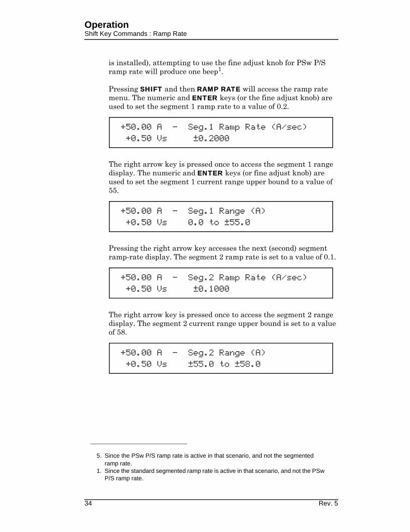
OperationShift Key Commands : Ramp Rate
is installed), attempting to use the fine adjust knob for PSw P/S ramp rate will produce one beep1.
Pressing SHIFT and then RAMP RATE will access the ramp rate menu. The numeric and ENTER keys (or the fine adjust knob) are used to set the segment 1 ramp rate to a value of 0.2.
The right arrow key is pressed once to access the segment 1 range display. The numeric and ENTER keys (or fine adjust knob) are used to set the segment 1 current range upper bound to a value of 55.
Pressing the right arrow key accesses the next (second) segment ramp-rate display. The segment 2 ramp rate is set to a value of 0.1.
The right arrow key is pressed once to access the segment 2 range display. The segment 2 current range upper bound is set to a value of 58.
5. Since the PSw P/S ramp rate is active in that scenario, and not the segmented
ramp rate.
1. Since the standard segmented ramp rate is active in that scenario, and not the PSw
P/S ramp rate.
+50.00 A - Seg.1 Ramp Rate (A/sec)+0.50 Vs ±0.2000
+50.00 A - Seg.1 Range (A)+0.50 Vs 0.0 to ±55.0
+50.00 A - Seg.2 Ramp Rate (A/sec)+0.50 Vs ±0.1000
+50.00 A - Seg.2 Range (A)+0.50 Vs ±55.0 to ±58.0
34 Rev. 5

OperationShift Key Commands : Ramp Rate
Pressing the right arrow key accesses the next (third) segment ramp rate display. The segment 3 ramp rate is set to a value of 0.05.
Pressing the right arrow key accesses the segment 3 current range display.
Note
Note that when there is more than one segment, the upper bound of the last segment is always the Magnet Current Rating1 (or the Current Limit if set lower than the Magnet Current Rating); it will be displayed as “±Limit” and cannot be edited.
Now, when current is in the range of 0 to ±55 A, ramping will be controlled at ±0.2 A/s. When current is in the range of ±55 to ±58 A, ramping will be controlled at ±0.1 A/s and when current is greater than ±58 A (up to the limit of 60 A), ramping will be controlled at ±0.05 A/s.
If ramp rate of a ramp segment is being edited while the Model 430 is ramping and the system current/field transitions from the currently edited segment to the next before the adjustment has been committed with the ENTER key, the adjusted value will be discarded. The display will update to show the new segment ramp rate, and the fine adjust knob will apply to the new segment (assuming the ENTER key is pressed before the segment has completed).
If at some later time it is desired to temporarily set the Current Limit to a new value lower than the Magnet Current Rating, for example 56 A, this lower value will override the Magnet Current Rating. Now only the first two ramp segments would be active since
1. Refer to section 3.10.2.4 on page 52 and section 3.10.2.3 on page 51.
+50.00 A - Seg.3 Ramp Rate (A/sec)+0.50 Vs ±0.0500
+50.00 A - Seg.3 Range (A)+0.50 Vs ±58.0 to ±Limit
Rev. 5 35
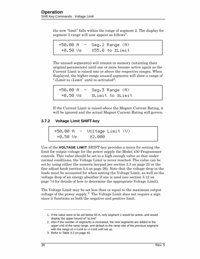
OperationShift Key Commands : Voltage Limit
the new “limit” falls within the range of segment 2. The display for segment 2 range will now appear as follows1.
The unused segment(s) will remain in memory (retaining their original parameters) until one or more become active again as the Current Limit is raised into or above the respective ranges. When displayed, the higher-range unused segments will show a range of “±Limit to ±Limit” until re-activated2.
If the Current Limit is raised above the Magnet Current Rating, it will be ignored and the actual Magnet Current Rating will govern.
3.7.2 Voltage Limit SHIFT-key
Use of the VOLTAGE LIMIT SHIFT-key provides a menu for setting the limit for output voltage for the power supply the Model 430 Programmer controls. This value should be set to a high enough value so that under normal conditions, the Voltage Limit is never reached. The value can be set by using either the numeric keypad per section 3.3 on page 25 or the fine adjust knob (section 3.4 on page 26). Note that the voltage drop in the leads must be accounted for when setting the Voltage Limit, as well as the voltage drop of an energy absorber if one is used (see section 3.12 on page 74 for details of how to determine the appropriate Voltage Limit).
The Voltage Limit may be set less than or equal to the maximum output voltage of the power supply.3 The Voltage Limit does not require a sign since it functions as both the negative and positive limit.
1. If the value were to be set below 55 A, only segment 1 would be active, and would
display the upper bound of “±Limit”.
2. Also if the number of segments is increased, the new segments are added to the
upper end of the ramp range, and default to the ramp rate of the previous segment
with the range of +/-Limit to +/-Limit until set up.
3. Refer to Table 3-2 on page 45.
+50.00 A - Seg.2 Range (A)+0.50 Vs ±55.0 to ±Limit
+50.00 A - Seg.3 Range (A)+0.50 Vs ±Limit to ±Limit
+50.00 A - Voltage Limit (V)+0.50 Vs ±2.000
36 Rev. 5
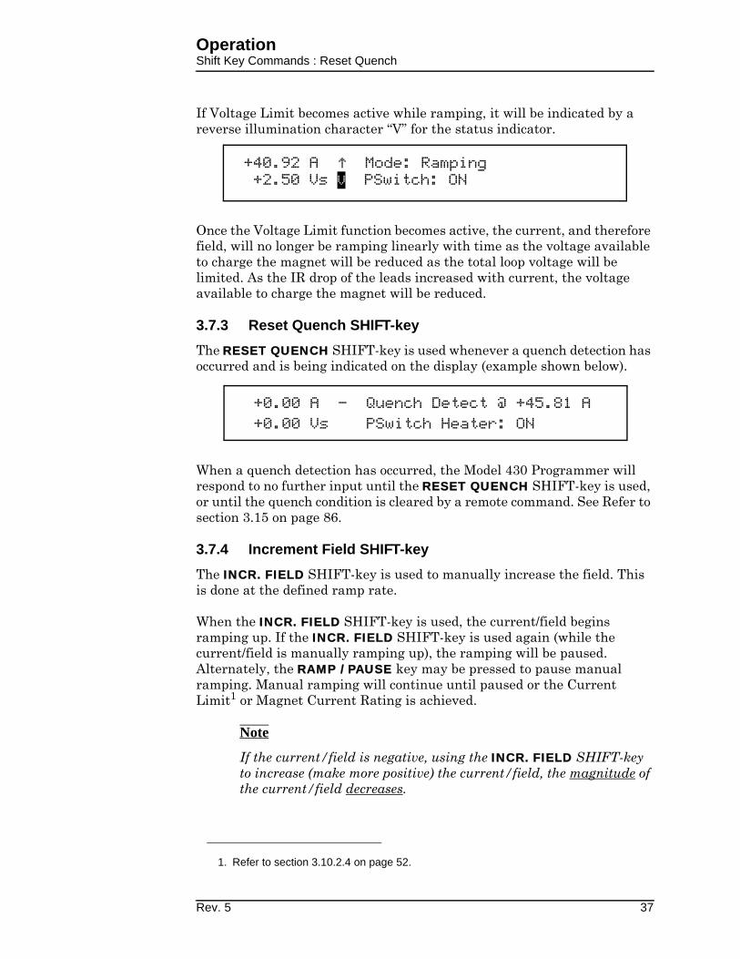
OperationShift Key Commands : Reset Quench
If Voltage Limit becomes active while ramping, it will be indicated by a reverse illumination character “V” for the status indicator.
Once the Voltage Limit function becomes active, the current, and therefore field, will no longer be ramping linearly with time as the voltage available to charge the magnet will be reduced as the total loop voltage will be limited. As the IR drop of the leads increased with current, the voltage available to charge the magnet will be reduced.
3.7.3 Reset Quench SHIFT-key
The RESET QUENCH SHIFT-key is used whenever a quench detection has occurred and is being indicated on the display (example shown below).
When a quench detection has occurred, the Model 430 Programmer will respond to no further input until the RESET QUENCH SHIFT-key is used, or until the quench condition is cleared by a remote command. See Refer to section 3.15 on page 86.
3.7.4 Increment Field SHIFT-key
The INCR. FIELD SHIFT-key is used to manually increase the field. This is done at the defined ramp rate.
When the INCR. FIELD SHIFT-key is used, the current/field begins ramping up. If the INCR. FIELD SHIFT-key is used again (while the current/field is manually ramping up), the ramping will be paused. Alternately, the RAMP / PAUSE key may be pressed to pause manual ramping. Manual ramping will continue until paused or the Current Limit1 or Magnet Current Rating is achieved.
Note
If the current/field is negative, using the INCR. FIELD SHIFT-key to increase (make more positive) the current/field, the magnitude of the current/field decreases.
1. Refer to section 3.10.2.4 on page 52.
+40.92 A Mode: Ramping+2.50 Vs V PSwitch: ON
+0.00 A - Quench Detect @ +45.81 A+0.00 Vs PSwitch Heater: ON
Rev. 5 37

OperationShift Key Commands : Field <> Current
3.7.5 Field <> Current SHIFT-key
The FIELD <> CURRENT SHIFT-key is used to toggle between the use of field units, either kG (kilogauss) or T (tesla), and the use of current units (A)1. If the Model 430 Programmer is using field units (either kG or T) and the FIELD <> CURRENT SHIFT-key is used, the Model 430 Programmer will begin using current units (A). Conversely, if the Model 430 is using current units (A) and the FIELD <> CURRENT SHIFT-key is used, the Model 430 will begin using field units (either kG or T).
Note
The Model 430 Programmer cannot use field units unless a valid coil constant has been entered2.
3.7.6 Decrement Field SHIFT-key
The DECR. FIELD SHIFT-key is used to manually decrease the current/field. This is done at the defined ramp rate.
When the DECR. FIELD SHIFT-key is used, the current/field begins ramping down. If the DECR. FIELD SHIFT-key is used again (while the current/field is manually ramping down), the ramping will be paused. Alternately, the RAMP / PAUSE key may be pressed to pause manual ramping. Manual ramping will continue until paused or the Current Limit3 or Magnet Current Rating is achieved.
Note
If the current/field is negative, using the DECR. FIELD SHIFT-key to decrease (make less positive) the current/field, the magnitude of the current/field increases.
3.7.7 Field Units SHIFT-key
Use of the FIELD UNITS SHIFT-key provides a shortcut to the picklist menu4 for defining whether the field is specified and displayed in units of kilogauss (kG) or tesla (T). The selected option also applies to remote interface commands. The default setting is kilogauss.
1. The value is always displayed in current (A) when an installed persistent switch is in
the cooled state since the value represents power supply current only, independent
of magnet current/field.
2. Refer to section 3.10.2.2 on page 50.
3. Refer to section 3.10.2.4 on page 52.
4. Refer to section 3.10.3.4 on page 60.
+50.00 A - Field Units+0.50 Vs Kilogauss Tesla
38 Rev. 5

OperationShift Key Commands : Persistent Switch Heater Current
3.7.8 Persistent Switch Heater Current SHIFT-key
Use of the P. SWITCH HTR. CUR. SHIFT-key provides a shortcut to the menu1 for setting persistent switch heater current. The value can be set to between 0.0 and 125.0 mA. The default value is 10.0 mA unless preset by AMI to match a specific superconducting magnet.
3.7.9 Stability SHIFT-key
Use of the STAB. SHIFT-key provides a shortcut to the menu for defining the Model 430 stability setting. The stability setting is specified in percent and controls the transient response and stability of the system. The valid input range is from 0.0 to 100.0%. The default value is 0.0% unless preset by AMI to match a specific superconducting magnet.
See section 3.10.2.1 on page 48 for details of how to determine the stability setting to use.
3.7.10 Vs <> Vm SHIFT-key
The Vs <> Vm SHIFT-key is used to toggle the voltage display between display of the voltage across the magnet (Vm) and the power supply output voltage (Vs). See section 3.2.2 on page 24 for details.
3.7.11 Volt Meter SHIFT-key
The VOLT METER SHIFT-key is used to toggle the main display between display of a voltmeter indicating magnet voltage (Vm) or supply voltage (Vs), and display of ramp mode and persistent switch heater state. See section 3.2.4 on page 25 for details.
3.7.12 Fine Adjust SHIFT-key
The FINE ADJUST SHIFT-key is used to enable the use of the front panel fine adjust knob to adjust numeric values. See section 3.4 on page 26 for details.
3.7.13 Persist. Switch Control SHIFT-key
Refer to section 3.6.1 on page 29.
1. Refer to section 3.10.2.8 on page 55.
+50.00 A — PSwitch Current (mA)+0.50 Vs 10.0
Rev. 5 39

OperationLED Indicators
3.8 LED Indicators
The Model 430 Programmer has six front panel LED indicators. See figure with Table 1-1 on page 5 for the location of these indicators.
3.8.1 Power-on Indicator
The green power-on LED indicates that the Model 430 Programmer is powered on.
3.8.2 Magnet Status Indicators
Four LEDs are grouped together to show the magnet status.
3.8.2.1 Field At Target Indicator
The green FIELD AT TARGET LED indicates that the current is at the target value. If the magnet is not in persistent mode (persistent switch heater is on), then this is an indication that the magnet field has reached the target value. If the magnet is in persistent mode, then this is an indication that the current being supplied to the magnet system has reached the target value.
3.8.2.2 Magnet In Persistent Mode Indicator
Caution
If the Model 430 Programmer power is turned off while the persistent switch is heated, persistent switch heating will be lost and the magnet will enter persistent mode. The Model 430 will not have a record of that event. Therefore the MAGNET IN PERSISTENT MODE LED state will be incorrect (remain OFF) when the Model 430 Programmer power is restored.
Caution
If the Model 430 Programmer power supply system is powered off and moved from one magnet system to another, the MAGNET IN PERSISTENT MODE LED may not correctly indicate the state of the
Figure 3-6. Magnet Status LED Indicators.
40 Rev. 5

OperationLED Indicators : Current Leads Energized
magnet system until the first time the persistent switch heater is turned off.
Also, should the magnet quench while the magnet is in persistent mode and the Model 430 Programmer is off, the persistent mode indicator LED will be incorrect when the Model 430 Programmer is turned on again.
The green MAGNET IN PERSISTENT MODE LED indicates that the persistent switch heater is off, and that when it was turned off, the magnet had greater than 100 mA of current flowing through it. The state of this LED is kept in nonvolatile memory when the Model 430 is powered off, so that the LED state is retained even during a power cycle of the Model 430. Thus, the MAGNET IN PERSISTENT MODE LED is an indicator that the magnet is persistent and has at least some persistent field.
3.8.2.3 Current Leads Energized Indicator
The blue CURRENT LEADS ENERGIZED LED indicates that at least 100 mA of current is flowing in the Model 430 power supply system output current leads.
3.8.2.4 Magnet Quench Indicator
The red MAGNET QUENCH LED indicates that a magnet quench condition has been detected. See section 3.15 on page 86 for details.
3.8.3 SHIFT Indicator
The green SHIFT LED indicates that the SHIFT key has been pressed, and the next numeric keypad key pressed will actuate the shifted function (shown in light blue) rather than the numeric keypad function. See section 3.7 on page 32 for details of SHIFT key use.
3.9 Setup Menu
Setup of the Model 430 Programmer requires the user to navigate the setup menu. Navigation of the setup menu is very intuitive — quite similar, for example, to the use of a cell phone menu.
3.9.1 Entering / Exiting Setup Menu
To enter the setup menu, simply press the MENU key. When in any of the setup menus, pressing the MENU key will exit the setup menu. The MENU key toggles the Model 430 Programmer in and out of setup mode. Alternately, if the top level setup menu is being displayed, pressing the ESC key exits the setup menu.
Rev. 5 41

OperationSetup Menu : Navigation
3.9.2 Menu Navigation
Pressing the MENU key enters the menu structure at the top level. The display will look approximately as shown below:
The item selector ( ) points to whichever submenu was last used. The left and right arrows at the ends of the displayed submenu selections indicate that there are other submenu selections off screen, to the left and/or right of the submenu selections shown.
The left and right keypad arrows (to the left and right of the MENU key) move the item selector between the different submenu items. Pressing the left keypad arrow moves the item selector one item to the left and pressing the right keypad arrow moves the item selector one item to the right. When the last item is reached, and the right keypad arrow is pressed, the item selector will move to the first item. Likewise, when the item selector is pointing to the first item, and the left keypad arrow is pressed, the item selector will move to the last item.
Pressing the ENTER key opens the submenu to which the item selector is pointing when the ENTER key is pressed. See sections 3.10.1 on page 43 through 3.10.5 on page 70 for detailed descriptions of each submenu.
Pressing the ESC key exits a submenu and moves the next higher level submenu if it exists. If the top level setup menu is being displayed, pressing the ESC key exits the setup menu.
3.10 Setup Submenu Descriptions
When a submenu is entered by selecting a submenu item and pressing ENTER (see section 3.9.2 on page 42 for details of menu navigation), the
+0.00 A - Setup Mode (Select one)
+0.50 Vs Supply Load Misc
42 Rev. 5

OperationSetup Submenu : Supply
user will be able to edit parameters under that submenu. See setup menu structure in Figure 3-7 below.
3.10.1 Supply Submenu
The Model 430 Programmer has been configured as part of the 4Q06125PS-430 Power Supply System. It should not be necessary to change this selection. However, the Supply submenu information that follows in Section 3.10.1 is provided in the event that the power supply system/model must be changed.
The Supply submenu provides for the specification of the power supply parameters. If you wish to set the limits of operation for a connected magnet, refer to the Current Limit1 and the Voltage Limit2 configuration sections.
1. Refer to section 3.10.2.4 on page 52.
2. Refer to section 3.7.2 on page 36.
LOAD
STABILITYSETTING
COILCONSTANT
CURRENTLIMIT
MAGNET CURRENTRATING
CALCULATE MAGNETINDUCTANCE
PSWITCHINSTALLED?
PSw CURRENTDETECT
PSWITCHCURRENT
PSWITCHHEATED TIME
PSWITCHCOOLED TIME
PSWITCHP/S RAMP RATE
PSWITCHCOOLING GAIN
ENABLE QUENCHDETECT?
ENERGY ABSORBERPRESENT?
EXTERNAL RAMP-DOWN DISABLED?
MISC
DISPLAYBRIGHTNESS
RAMPSEGMENTS
RAMP RATETIME UNITS
FIELDUNITS
QUENCHRATE
SETTINGSPROTECTION
SETTINGSPASSWORD
SETUP MENU
SUPPLY
SELECT SUPPLY
CUSTOM
MIN OUTPUTVOLTAGE
MAX OUTPUTVOLTAGE
MIN OUTPUTCURRENT
MAX OUTPUTCURRENT
V-V MODEINPUT RANGE
NET SETTINGS
ADDRESSASSIGNMENT
SYSTEMNAME
IPADDRESS
SUBNETMASK
GATEWAYADDRESS
NET SETUP
IP ADDRESSASSIGNMENT
SYSTEM IPADDRESS
SUBNETMASK
GATEWAY IPADDRESS
AMI 12100PS
AMI 12200PS
AMI 4Q05100PS
AMI 4Q06125PS
AMI 4Q06250PS
AMI 4Q12125PS
AMI 10100PS
OTHERS…
0 to -5
0 to +5
0 to +10
-5 to +5
-10 to +10
NET SETUPNET SETTINGS NET SETUPMISC NET SETTINGS NET SETUPLOAD MISC NET SETTINGS NET SETUPSUPPLY LOAD MISC NET SETTINGS NET SETUP
SELECT SUPPLYSELECT SUPPLY
CUSTOM
SELECT SUPPLY
CUSTOM
SELECT SUPPLY
Figure 3-7. Setup Menu Structure
Rev. 5 43

OperationSetup Menu : Supply
If using a standard power supply supported by AMI, selecting a power supply within the Select Supply picklist sets all the remaining parameters in the supply submenu per Table 3-2 on page 45.
Note
The Supply submenu is unique in that it has only the Select Supply picklist as a sublevel (unless Custom is chosen from the picklist of Select Supply options). For this reason, picklist entry is active as soon as the Supply submenu is selected; it is not necessary to first press enter to make picklist entry active in the Select Supply picklist. Also, pressing ESC while within the Select Supply picklist not only makes picklist entry inactive and sets the picklist selection back to where it was when the Supply submenu was selected; it also exits the Select Supply picklist.
3.10.1.1 Select Supply Picklist
The Select Supply picklist provides a set of picklist items that contain presets for standard AMI power supplies. The left and right keypad arrows are used to cycle through the list of selections. When the item selector points at the desired power supply in the picklist, ENTER is pressed to select that power supply; all power supply parameters are set when the power supply model is selected. Pressing ESC while viewing the Select Supply picklist leaves the power supply selection where it was when the Supply submenu was selected, and exits the Select Supply picklist. The available Select Supply picklist values and associated power supply parameters are provided in Table 3-2 on page 45.
+0.00 A — Select Supply*
+0.50 Vs AMI 4Q06125PS
44 Rev. 5

OperationSetup Menu : Supply
t
AM 0
AM0
AM
AM
00AM
AM
AM
AM0
AM
AM
0
AM
AM
AM
AM
HP
Kep00
Kep
Xan 0
Cus 00
Note
The current must be less than 0.1% of Imax in order to change the Select Supply picklist value. If a change is attempted with current above this value, the Model 430 Programmer will beep and ignore
Table 3-2. Select Supply picklist values and associated parameters.
Power Supply
Min Output
Voltage (V)
Max Output
Voltage (V)
Min Output
Current (A)
Max Output
Current (A)
V-V Mode Inpu
Range (V)
I 08150PS 0 +8.000 +0.0000 +150.000 +0.000 to +10.00
I 12100PS+0.000 +12.000 +0.000
+100.000+0.000 to +10.00
I 12200PS +200.000
I 4Q05100PS −5.000 +5.000 −100.000 +100.000
−10.000 to +10.0I 4Q06125PS
-6.000 +6.000-125.000 +125.000
I 4Q06250PS -250.000 +250.000
I 4Q12125PS -12.000 +12.000 -125.000 +125.000
I 10100PS
+0.000
+10.000
+0.000
+100.000+0.000 to +5.00
I 10200PS +200.000
I 05100PS
+10.000a
+100.000
+0.000 to +10.00
I 05200PS +200.000
I 05300PS +300.000
I 05400PS +400.000
I 05500PS +500.000
6260B
+10.000
+100.000
co BOP 20-5Mb
−10.000
−5.000 +5.000
−10.000 to +10.0
co BOP 20-10Mb −10.000 +10.000
trex XFR 7.5-140 +0.000 +7.500 +0.000 +140.000 +0.000 to +10.00
tom...c −20.000 +20.000 −200.000 +200.000 −10.000 to +10.0
a. The individual 05100PS power supply unit will source +10.000 Vdc at 100 A. How-
ever, the standard configuration of this series of power supplies includes the Model
601 Energy Absorber to provide bipolar operation. The 05x00-430-601 series of
power supply systems provides a maximum available voltage to the load of ±5.000
Vdc at multiples of 100 A, up to 500 A depending on the system selected.
b. The Kepco BOP power supplies are limited to only one-half the output voltage
range since the supplies are designed to safely dissipate only one-half the rated
power output.
c. The values shown for the Custom... option are defaults. The user should enter the
appropriate values within the respective submenus. Custom values, once entered,
are saved in nonvolatile memory.
Rev. 5 45

OperationSetup Menu : Supply
the keypress. Power supply selection should also preferably be performed with the power supply off for maximum safety.
The power supply settings define the output voltage and current ranges for a specific power supply. For example, V-I diagrams are presented in Figure 3-8 for the AMI 12100PS and AMI 4Q06125PS selections. The AMI 12100PS operates as a one-quadrant system without the addition of an energy absorber. As shown in the diagram, with the addition of an AMI Model 601 energy absorber, the AMI 12100PS system can function as a two-quadrant supply providing +5 V to -5 V at the power supply system output terminals. The AMI 4Q06125PS power supply operates as a four-quadrant power supply without the addition of an energy absorber.
The addition of an energy absorber to the system does not change the capabilities of the power supply itself (or the values entered for the supply). The addition of an energy absorber does, however, change the system operating ranges per the example of Figure 3-8.
3.10.1.1.1 Custom... Picklist Item
Custom... is a unique Select Supply picklist item. When selected, it opens a deeper submenu in which the custom power supply parameters (Min Output Voltage, Max Output Voltage, Min Output Current, Max Output Current and V-V Mode Input Range) are entered. Entry of each of these parameters is described below.
Figure 3-8. Example Power Supply Outputs
46 Rev. 5

OperationSetup Menu : Supply
3.10.1.1.1.1 Min Output Voltage
The minimum output voltage is specified in volts (V) and reflects the minimum output voltage compliance of a connected power supply. The valid range is 0.000 to -20.000 V, and can be set by using either the numeric keypad per section 3.3 on page 25 or the fine adjust knob (section 3.4 on page 26). A unipolar power supply has a minimum output voltage of 0.000 V.
3.10.1.1.1.2 Max Output Voltage
The maximum output voltage is specified in volts (V) and reflects the maximum output voltage compliance of a connected power supply. The valid range is +0.001 to +20.000 V, and can be set by using either the numeric keypad per section 3.3 on page 25 or the fine adjust knob (section 3.4 on page 26).
3.10.1.1.1.3 Min Output Current
The minimum output current is specified in amperes (A) and reflects the minimum output current capacity of a connected power supply. The valid range is 0.000 to -2000.000 A1, and can be set by using either the numeric keypad per section 3.3 on page 25 or the fine adjust knob (section 3.4 on page 26). A unipolar power supply has a minimum output current of 0.000 A.
1. The minimum and maximum output currents are bounded by the Model 430 Pro-
grammer configuration (refer to specifications on page 8 and in the Appendix). The
entered value cannot exceed the programmable limits.
+0.00 A — Min Output Voltage (V)+0.00 Vs -6.000
+0.00 A — Max Output Voltage (V)+0.00 Vs +6.000
+0.00 A — Min Output Current (A)+0.00 Vs +0.000
Rev. 5 47

OperationSetup Submenu : Load
3.10.1.1.1.4 Max Output Current
The maximum output current is specified in amperes (A) and reflects the maximum output current capacity of a connected power supply. The valid range is 0.001 to +2000.000 A1, and can be set by using either the numeric keypad per section 3.3 on page 25 or the fine adjust knob (section 3.4 on page 26).
3.10.1.1.1.5 V-V Mode Input Range
The voltage-to-voltage mode input range defines the remote programming voltage input range required by the connected power supply. The remote programming voltage is the output signal provided by the Model 430 Programmer as an input to the connected power supply.
This submenu item provides a picklist of six preset selections and does not allow numeric entry of a range. The picklist values are shown in Table 3-3 below.
3.10.2 Load Submenu
When the Load submenu is selected, several parameters associated with the superconducting magnet load can be viewed and/or changed.
3.10.2.1 Stability Setting
The stability setting is specified in percent and controls the transient response and stability of the system. The value can be set
Table 3-3. V-V Mode Input Range Picklist Values
+0.000 to -5.000 +0.000 to +8.000
+0.000 to +5.000 -5.000 to +5.000
+0.000 to +10.000 -10.000 to +10.000
+0.00 A — Max Output Current (A)+0.00 Vs +100.000
+0.00 A — V-V Mode Input Range (V)+0.00 Vs -10.000 to +10.000
+0.00 A — Stability Setting (%)+0.50 Vs 0.0
48 Rev. 5

OperationSetup Menu : Load
by using either the numeric keypad per section 3.3 on page 25 or the fine adjust knob (section 3.4 on page 26). The valid range is from 0.0 to 100.0%. The default value is 0.0% unless preset by AMI to match a specific superconducting magnet.
Superconducting magnets without a persistent switch require1 a specific Model 430 Programmer stability setting based on the magnet inductance as follows:
For magnet inductance <= 100 Henries (H):Stability Setting = (100 - H)
For magnet inductance > 100 Henries:Stability Setting = 0
The graph below may be used as a guide to set the stability setting for magnets with a persistent switch installed and inductance of less than 3 henries. Magnets with an inductance of greater than 3 henries that have a persistent switch installed should operate with a stability setting of 0.0%.
The Model 430 Programmer internal control loop gain is proportional to the multiplier (100% – [Stability Setting]), except that for a Stability of 100% the multiplier is set to a low non-zero value suitable for controlling current in a short circuit. For this
1. Effective with Model 430 firmware version 1.62.
y g g
0
10
20
30
40
50
60
70
80
90
100
0 1 2 3 4 5 6 7
Inductance (H)
Sta
bil
ity
Se
ttin
g (
%)
Figure 3-9. Stability Setting vs. Magnet (with PSwitch) Inductance
Model 430 Stability Setting vs. Magnet Inductance(for Magnets with Persistent Switch)
Rev. 5 49

OperationSetup Menu : Load
reason, small changes in Stability Setting have a large effect on stability as the Stability Setting value approaches 100%. Changing the Stability Setting from 99.9% to 99.8% changes the gain multiplier from 0.1% to 0.2% (changing the gain multiplier by a factor of 2, a 100% increase in the gain multiplier). Note, however, that the same 0.1% change in Stability Setting from 90% to 89.9% only changes the gain multiplier from 10% to 10.1% (changing the gain multiplier by a factor of 1.01, a 1% change in gain multiplier). Likewise a 0.1% change in Stability Setting from 50% to 49.9% only changes the gain multiplier from 50% to 50.1% (changing the gain multiplier by a factor of only 1.002, a 0.2% increase in the gain multiplier).
What this means is that if the Stability Setting is being adjusted to experimentally determine its optimum setting (using the graph above as a starting point), no greater than 0.1% changes should be made above 98%, no greater than 0.2% changes should be made between 94% and 98%, no greater than 0.5% changes should be made between 84% and 94%, no greater than 2% changes should be made between 44% and 84% and no greater than 5% changes should be made below 44%. See the summary in the table below.
3.10.2.2 Coil Constant
The coil constant is a scaling factor which converts the current to kilogauss (kG) or tesla (T). It is also often referred to as the field-to-current ratio. The coil constant is specified in kilogauss/ampere or tesla/ampere. The value can be set by using either the numeric keypad per section 3.3 on page 25 or the fine adjust knob (section 3.4 on page 26). If the coil constant value is 0.0 kG/A (or 0.0 T/A), then no conversion from amperes to kilogauss or tesla is
Table 3-4. Maximum Recommended Stability Setting Changes
Stability Setting Range
Maximum Recommended
Stability Setting Change
98% to 100% 0.1%
94% to 98% 0.2%
84% to 94% 0.5%
44% to 84% 2%
0% to 44% 5%
+0.00 A — Coil Constant (kG/A)+0.50 Vs 0.90000
50 Rev. 5

OperationSetup Menu : Load
performed — all operations will be performed and displayed in terms of amperes. Values from 0.001 to 999.99999 are acceptable for coil constant. The default value is 1.00000 kG/A (or 0.10000 T/A) unless preset by AMI to match a specific superconducting magnet.
If the coil constant is not explicitly stated within a superconducting magnet’s specifications, the value can be obtained by dividing the rated field by the rated current. Note that 1 T = 10 kG.
3.10.2.3 Magnet Current Rating
Caution
The Magnet Current Rating is normally set to match a specific superconducting magnet. The setting should not be changed unless a different magnet is to be used; always refer to the magnet specification before changing the Magnet Current Rating.
A magnet operates within the capabilities of the associated power supply. Since the supply must be selected from the available standard ratings, the current limit of the supply, which is not user-adjustable, is almost always higher than the Magnet Current Rating.
The Magnet Current Rating is normally preset by AMI to match a specified superconducting magnet. If AMI is not supplying the
+0.00 A P Magnet Current Rating (A)+0.00 Vm ±100.000
Figure 3-10. Typical Power Supply Self-Limits
Rev. 5 51

OperationSetup Menu : Load
magnet, and specific magnet data has not been provided by the customer, the Model 430 will ship with Magnet Current Rating set at the default value of 80 A. Figure 3-11 shows the default Magnet Current Rating as set within the 4Q06125PS power supply limits.
The Magnet Current Rating can be set by using either the numeric keypad per section 3.3 on page 25 or the fine adjust knob (section 3.4 on page 26). The Model 430 Programmer will beep once and deny the change if the user attempts to set the Magnet Current Rating below the present Target Field Setpoint.
If a lower current limit is required for testing or other purposes, the Current Limit (see section 3.10.2.4) can be set by the user to limit the magnet current to values lower than the Magnet Current Rating.
3.10.2.4 Current Limit
The current to the load will be limited by the lower of the two Model 430 current limits, the Magnet Current Rating1 or Current Limit setting.
1. Refer to section 3.10.2.3 on page 51.
Figure 3-11. Magnet Current Rating Set Within Supply Range
+0.00 A — Current Limit (A)+0.50 Vs ±50.000
52 Rev. 5

OperationSetup Menu : Load
The Current Limit setting can be used to limit the magnet current to values lower than the Magnet Current Rating for testing or other purposes (refer to Figure 3-12).
The value can be set by using either the numeric keypad per section 3.3 on page 25 or the fine adjust knob (section 3.4 on page 26). The Current Limit is specified as an absolute value, but if the power supply is four quadrant, the Current Limit applies to both the positive and the negative current direction (current limit symmetry). The Model 430 Programmer will beep once and deny the change if the user attempts to set the Current Limit below the present Target Field Setpoint.
3.10.2.5 Calculate Magnet Inductance
This menu pick will automatically determine the inductance of the load magnet. The inductance is determined by measuring the voltage developed across the magnet (Vm) with a fixed di/dt (current rate-of-change in A/sec) passed through the load. The function must be executed with the magnet ramping.1 After the function is executed by pressing the ENTER key, the algorithm will wait for 2 seconds to allow the current charge rate to stabilize and
1. Refer to section 3.12.3 on page 76.
Figure 3-12. Example Current Limit Setup
+00.00 A — Magnet Inductance (H)+0.00 Vs Calculate
Rev. 5 53
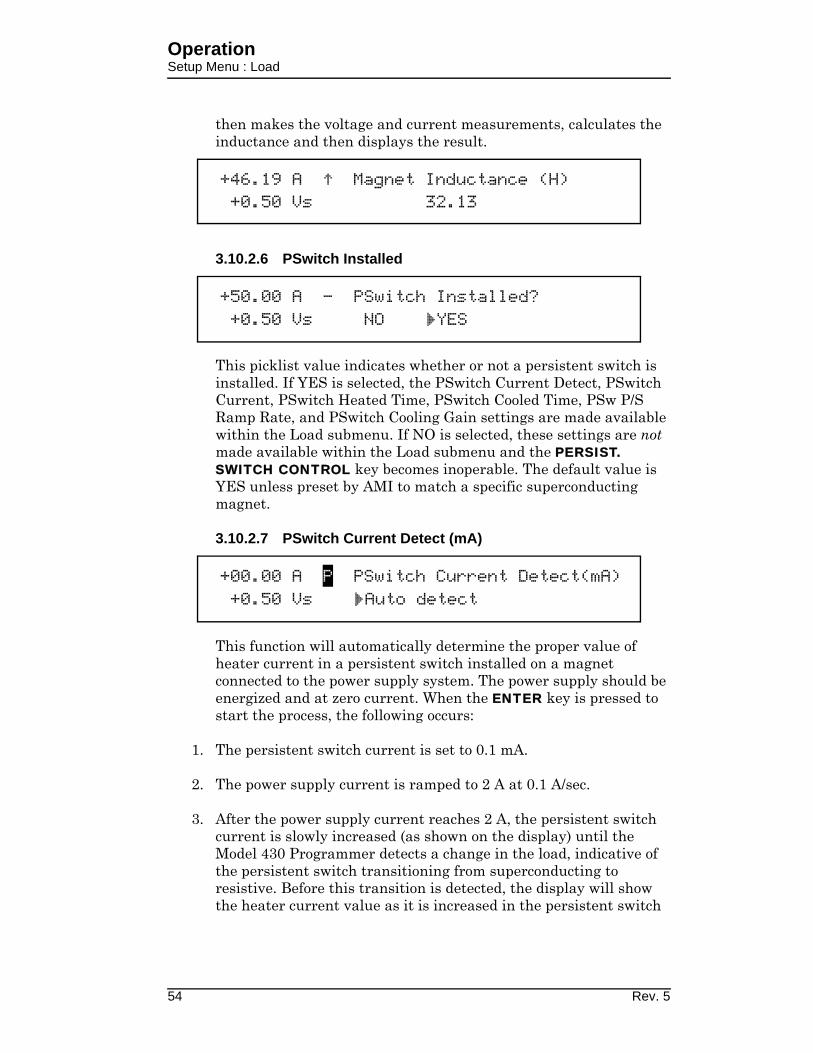
OperationSetup Menu : Load
then makes the voltage and current measurements, calculates the inductance and then displays the result.
3.10.2.6 PSwitch Installed
This picklist value indicates whether or not a persistent switch is installed. If YES is selected, the PSwitch Current Detect, PSwitch Current, PSwitch Heated Time, PSwitch Cooled Time, PSw P/S Ramp Rate, and PSwitch Cooling Gain settings are made available within the Load submenu. If NO is selected, these settings are not made available within the Load submenu and the PERSIST. SWITCH CONTROL key becomes inoperable. The default value is YES unless preset by AMI to match a specific superconducting magnet.
3.10.2.7 PSwitch Current Detect (mA)
This function will automatically determine the proper value of heater current in a persistent switch installed on a magnet connected to the power supply system. The power supply should be energized and at zero current. When the ENTER key is pressed to start the process, the following occurs:
1. The persistent switch current is set to 0.1 mA.
2. The power supply current is ramped to 2 A at 0.1 A/sec.
3. After the power supply current reaches 2 A, the persistent switch current is slowly increased (as shown on the display) until the Model 430 Programmer detects a change in the load, indicative of the persistent switch transitioning from superconducting to resistive. Before this transition is detected, the display will show the heater current value as it is increased in the persistent switch
+46.19 A Magnet Inductance (H)+0.50 Vs 32.13
+50.00 A — PSwitch Installed?+0.50 Vs NO YES
+00.00 A P PSwitch Current Detect(mA)+0.50 Vs Auto detect
54 Rev. 5

OperationSetup Menu : Load
heater; the magnet current is changed back to zero during this process.
4. 5 mA is added to the current that was present during the superconducting to resistive transition and that value of current is displayed.
Note
If the PSw current determined by this method is accepted as described below, the magnet will be in the heated switch mode at zero amps being delivered to the magnet.
5. If the ENTER key is pressed, the determined value of PSw current is stored in the Model 430 Programmer. If the escape key is pressed, the value determined in step 4, above is discarded and the previously set persistent switch current is retained.
3.10.2.8 PSwitch Current
The persistent switch heater current can be set to any value between 0.0 and 125.0 mA. The value can be set by using either the numeric keypad per section 3.3 on page 25 or the fine adjust knob (section 3.4 on page 26). The default value is 10.0 mA unless preset by AMI to match a specific superconducting magnet.
3.10.2.9 PSwitch Heated Time
The persistent switch heated time is the amount of time required for the persistent switch to heat completely and become fully normal (resistive). The time may be set to any value between 5 and
+2.00 A P PSwitch Current Detect(mA)+0.50 Vs Detecting...(20.7mA)
+00.00 A P PSwitch Current Detect(mA)+0.50 Vs 37.2
+50.00 A — PSwitch Current (mA)+0.50 Vs 10.0
+50.00 A — PSwitch Heated Time (sec)+0.50 Vs 20
Rev. 5 55

OperationSetup Menu : Load
120 seconds1. The value can be set by using either the numeric keypad per section 3.3 on page 25 or the fine adjust knob (section 3.4 on page 26). The default is 20 seconds unless preset by AMI to match a specific superconducting magnet.
During the persistent switch heating period, the Model 430 Programmer ramping functions are disabled. The time delay is necessary to ensure that the Model 430 will not switch to the higher gain required for proper magnet operation before the magnet is actually available in the circuit (not being shunted by the persistent switch). If magnet operation is not stable after expiration of the heating period, increase the heated time to allow more time for the switch to heat. The default value of 20 seconds is adequate for the majority of wet and dry persistent switches.
3.10.2.10 PSwitch Cooled Time
The PSwitch Cooled Time is the amount of time required for the persistent switch to cool completely and become fully superconducting. The time may be set to any value between 5 and 3600 seconds2. The value can be set by using either the numeric keypad per section 3.3 on page 25 or the fine adjust knob (section 3.4 on page 26). The default is 20 seconds unless preset by AMI to match a specific superconducting magnet.
During the persistent switch cooling period, the Model 430 Programmer ramping functions are disabled. The default value of 20 seconds is adequate for the majority of wet persistent switches. Persistent switches on conduction cooled magnets (dry switches) will require significantly longer cooling times than wet switches.
3.10.2.11 PSwitch Power Supply Ramp Rate
The persistent switch power supply ramp rate is the rate at which the magnet power supply will automatically be ramped up or down while an installed persistent switch is in the cooled state. The rate
1. During the heating cycle, a “countdown” will be displayed indicating the number of
seconds remaining in the cycle.
2. During the cooling cycle, a “countdown” will be displayed indicating the number of
seconds remaining in the cycle.
+50.00 A — PSwitch Cooled Time (sec)+0.50 Vs 20
+50.00 A — PSw P/S Ramp Rate (A/sec)+0.50 Vs 10
56 Rev. 5

OperationSetup Menu : Load
may be set to any value between 0.1 and 10 A/sec. The value can be set by using either the numeric keypad per section 3.3 on page 25 or the fine adjust knob (section 3.4 on page 26). The default is 10 A/sec unless preset by AMI to match a specific superconducting magnet system.
3.10.2.12 PSwitch Cooling Gain
The default cooling gain of 0.0% may be adequate for the majority of wet persistent switches. However, this setting may result in some magnet drift during persistent switch cooling, especially with conduction cooled switches. Increasing the cooling gain adds control loop gain during the switch cooling cycle. Too little may result in magnet drift during switch cooling. Too much may result in power supply instability during switch cooling, which could potentially prevent the switch from cooling. Most systems requiring some cooling gain to control magnet drift will likely work with value set to about 25%. The value can be set by using either the numeric keypad per section 3.3 on page 25 or the fine adjust knob (section 3.4 on page 26).
3.10.2.13 Enable Quench Detect
The internal quench detection function of the Model 430 Programmer may be enabled or disabled according to the preference of the user. The default value is NO.
A user input for external quench detection is provided on the rear panel of the Model 430 Programmer1. The external input overrides the internal quench detection function of the Model 430 and cannot be disabled. For further discussion of the quench detection logic and operation, please refer to section 3.15 on page 86.
1. Refer to section A.5.1 on page 149.
+0.00 A P PSwitch Cooling Gain (%)+0.00 Vs 0.0
+50.00 A — Enable Quench Detect?+0.50 Vs NO YES
Rev. 5 57

OperationSetup Menu : Load
3.10.2.14 Energy Absorber Present
This picklist value indicates whether an energy absorber, such as the AMI Model 601, is connected to the power supply system. The default setting is NO.
It is important for this setting to be correct since the internal gain tables of the Model 430 Programmer compensate for the additional load of the energy absorber if present. The increased gain when an energy absorber is present will decrease (but not eliminate) the time required for the system to “forward bias” the energy absorber.1
3.10.2.15 Enable External Rampdown
The External Rampdown function of the Model 430 Programmer can be used to allow an external contact-signal to cause the magnet to be ramped to zero field (even if it is in persistent mode) should a fault or alarm occur in a magnet system. Signals such as low liquid levels, cryocooler compressor faults, or abnormal temperatures can be used to trigger a controlled magnet rampdown, even if the magnet is in persistent mode. Refer to section 5.2 on page 150.
The external rampdown function may be enabled or disabled according to the preference of the user. The default value is NO. With the exception of enable yes/no, the settings and parameters for the external rampdown function can be edited only via the remote interface (see section 4.5.5 on page 120).
A user input for external rampdown detection is provided on the rear panel of the Model 430 Programmer2. For further discussion of the quench detection logic and operation, please refer to section 3.16 on page 88.
1. The Model 430 Programmer will bring the output voltage of the power supply to the
point where the energy absorber can provide current to the magnet.
2. Refer to section A.5.2 on page 150.
+50.00 A — Energy Absorber Present?+0.50 Vs NO YES
+0.00 A — External Rampdown Enabled?+0.00 Vs NO YES
58 Rev. 5

OperationSetup Submenu : Misc
3.10.3 Misc Submenu
When the Misc submenu is selected, several miscellaneous parameters may be viewed and/or changed.
3.10.3.1 Display Brightness
This picklist value controls display brightness. As shown above, there are four brightness settings from which to choose (25%, 50%, 75% and 100%). The default setting is 100%.
3.10.3.2 Ramp Segments
The ramp segments value specifies the number of current ranges which can be given unique ramp rate values. The default value is 1 unless preset by AMI to match a specific superconducting magnet.
When this value is 1, there is only one ramp rate for the Model 430 Programmer, used for the full available current range. For multiple ramp rates, set the value to the number of ramp segments desired (up to ten segments). See section 3.7.1 on page 33 for details regarding the use of ramp rate segments.
3.10.3.3 Ramp Rate Time Units
This picklist value specifies the unit of time used to enter and the display ramp rate. If Seconds is selected, ramp rate is entered in A/s, kG/s or T/s; if Minutes is selected, ramp rate is entered in A/min, kG/min or T/min. The selected unit value also applies to remote interface commands. The default setting is Seconds.
+50.00 A — Display Brightness (%)+0.50 Vs 25 50 75 100
+50.00 A — Ramp Segments (1-10)+0.50 Vs 1
+50.00 A — Ramp Rate Time Units+0.50 Vs Seconds Minutes
Rev. 5 59

OperationSetup Menu : Misc
3.10.3.4 Field Units
This picklist value specifies whether the field is specified and displayed in units of kilogauss (kG) or tesla (T). The units selected also applies to remote interface commands. The default setting is kilogauss.
3.10.3.5 Quench Rate
This picklist value specifies the sensitivity of the quench detection algorithm. The default value (1.5) will be appropriate for most magnets. Occasionally, some magnets quench very slowly and the value of this parameter may need to be adjusted to a lower value so that the Model 430 Programmer detects the slow quench. The available range for this parameter is 0.1 to 2.0. The value can be set by using either the numeric keypad per section 3.3 on page 25 or the fine adjust knob (section 3.4 on page 26). If the magnet quenches and the Model 430 Programmer does not select the quench, the value should be lowered until all quenches are detected.
3.10.3.6 Settings Protection
Settings Protection allows virtually1 every command and menu/submenu setting to be protected from alteration or use. If a setting is locked, it cannot be used from the front panel without first unlocking the setting, which requires entering the correct password. Note that settings protection only applies to front panel access, and not to remote access (via Ethernet or RS-232).
The use of settings protection allows specific commands and/or settings to be locked by a magnet system “administrator,” so that
1. The one exception is the RAMP TO ZERO button which cannot be locked. Also,
Magnet Inductance and Net Settings are not subject to locking due to their “read-
only” nature.
+50.00 A — Field Units+0.50 Vs Kilogauss Tesla
+50.00 A P Quench Rate (default 1.5)+0.50 Vs 1.5
+50.00 A — Settings Protection+0.50 Vs Edit Settings
60 Rev. 5
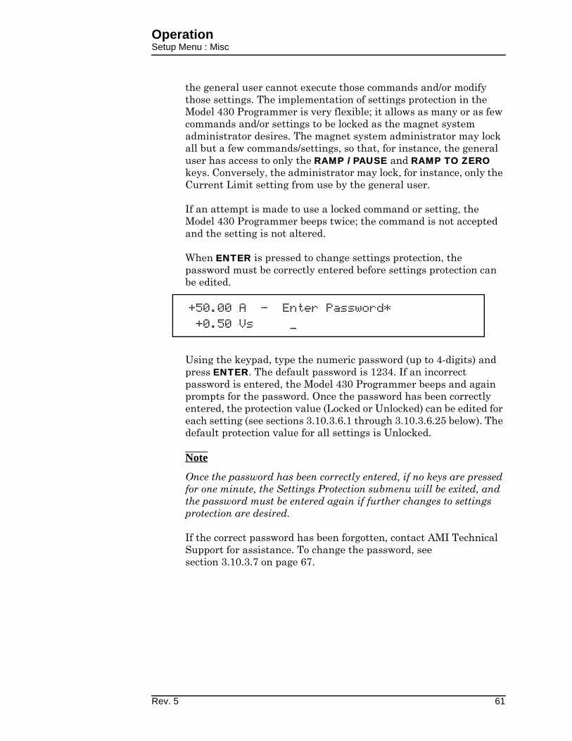
OperationSetup Menu : Misc
the general user cannot execute those commands and/or modify those settings. The implementation of settings protection in the Model 430 Programmer is very flexible; it allows as many or as few commands and/or settings to be locked as the magnet system administrator desires. The magnet system administrator may lock all but a few commands/settings, so that, for instance, the general user has access to only the RAMP / PAUSE and RAMP TO ZERO keys. Conversely, the administrator may lock, for instance, only the Current Limit setting from use by the general user.
If an attempt is made to use a locked command or setting, the Model 430 Programmer beeps twice; the command is not accepted and the setting is not altered.
When ENTER is pressed to change settings protection, the password must be correctly entered before settings protection can be edited.
Using the keypad, type the numeric password (up to 4-digits) and press ENTER. The default password is 1234. If an incorrect password is entered, the Model 430 Programmer beeps and again prompts for the password. Once the password has been correctly entered, the protection value (Locked or Unlocked) can be edited for each setting (see sections 3.10.3.6.1 through 3.10.3.6.25 below). The default protection value for all settings is Unlocked.
Note
Once the password has been correctly entered, if no keys are pressed for one minute, the Settings Protection submenu will be exited, and the password must be entered again if further changes to settings protection are desired.
If the correct password has been forgotten, contact AMI Technical Support for assistance. To change the password, see section 3.10.3.7 on page 67.
+50.00 A — Enter Password*+0.50 Vs _
Rev. 5 61

OperationSetup Menu : Misc
3.10.3.6.1 PSwitch Control Lock
This picklist value specifies whether use of the PERSIST. SWITCH CONTROL key is locked or unlocked. The default value is Unlocked.
3.10.3.6.2 Target Field Setpt Lock
This picklist value specifies whether use of the TARGET FIELD SETPOINT key is locked or unlocked. The default value is Unlocked.
3.10.3.6.3 Ramp / Pause Lock
This picklist value specifies whether use of the RAMP / PAUSE key is locked or unlocked. The default value is Unlocked.
3.10.3.6.4 Ramp To Zero Lock
This picklist value specifies whether use of the RAMP TO ZERO key is locked or unlocked. The default value is Unlocked.
3.10.3.6.5 Ramp Rate Settings Lock
This picklist value specifies whether ramp rate settings are locked or unlocked. Ramp rate settings protected by this setting are: use of the RAMP RATE SHIFT-key menu, editing of the Ramp Segments
+50.00 A — PSwitch Control Lock+0.50 Vs Locked Unlocked
+50.00 A — Target Field Setpt Lock+0.50 Vs Locked Unlocked
+50.00 A — Ramp / Pause Lock+0.50 Vs Locked Unlocked
+50.00 A — Ramp To Zero Lock+0.50 Vs Locked Unlocked
+50.00 A — Ramp Rate Settings Lock+0.50 Vs Locked Unlocked
62 Rev. 5
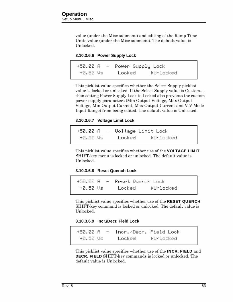
OperationSetup Menu : Misc
value (under the Misc submenu) and editing of the Ramp Time Units value (under the Misc submenu). The default value is Unlocked.
3.10.3.6.6 Power Supply Lock
This picklist value specifies whether the Select Supply picklist value is locked or unlocked. If the Select Supply value is Custom..., then setting Power Supply Lock to Locked also prevents the custom power supply parameters (Min Output Voltage, Max Output Voltage, Min Output Current, Max Output Current and V-V Mode Input Range) from being edited. The default value is Unlocked.
3.10.3.6.7 Voltage Limit Lock
This picklist value specifies whether use of the VOLTAGE LIMIT SHIFT-key menu is locked or unlocked. The default value is Unlocked.
3.10.3.6.8 Reset Quench Lock
This picklist value specifies whether use of the RESET QUENCH SHIFT-key command is locked or unlocked. The default value is Unlocked.
3.10.3.6.9 Incr./Decr. Field Lock
This picklist value specifies whether use of the INCR. FIELD and DECR. FIELD SHIFT-key commands is locked or unlocked. The default value is Unlocked.
+50.00 A — Power Supply Lock+0.50 Vs Locked Unlocked
+50.00 A — Voltage Limit Lock+0.50 Vs Locked Unlocked
+50.00 A — Reset Quench Lock+0.50 Vs Locked Unlocked
+50.00 A — Incr./Decr. Field Lock+0.50 Vs Locked Unlocked
Rev. 5 63

OperationSetup Menu : Misc
3.10.3.6.10 Field <> Current Lock
This picklist value specifies whether use of the FIELD <> CURRENT SHIFT-key command is locked or unlocked. The default value is Unlocked.
3.10.3.6.11 Field Units Lock
This picklist value specifies whether the Field Units value is locked or unlocked (whether accessed through the FIELD UNITS SHIFT-key menu or under the Misc submenu). The default value is Unlocked.
3.10.3.6.12 Stability Setting Lock
This picklist value specifies whether the Stability Setting value is locked or unlocked (whether accessed through the STAB. SHIFT-key menu or under the Load submenu). The default value is Unlocked.
3.10.3.6.13 Vs <> Vm Lock
This picklist value specifies whether use of the Vs <> Vm SHIFT-key command is locked or unlocked. The default value is Unlocked.
+50.00 A — Field <> Current Lock+0.50 Vs Locked Unlocked
+50.00 A — Field Units Lock+0.50 Vs Locked Unlocked
+50.00 A — Stability Setting Lock+0.50 Vs Locked Unlocked
+50.00 A — Vs <> Vm Lock+0.50 Vs Locked Unlocked
64 Rev. 5
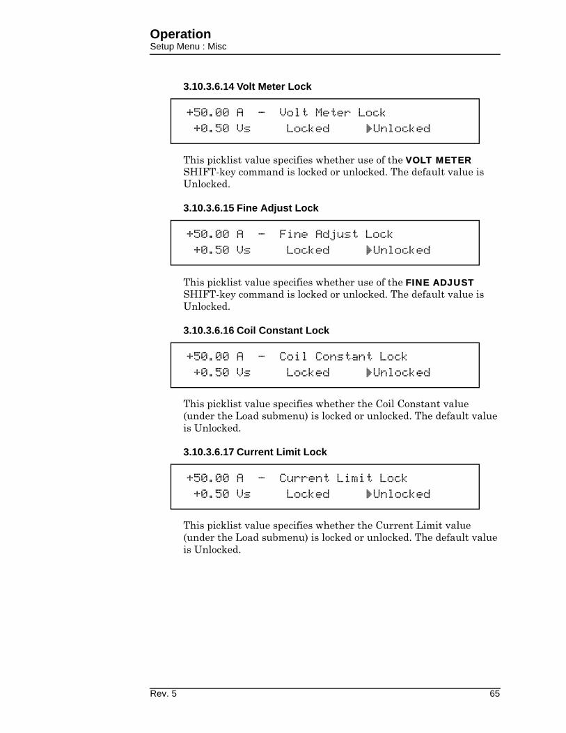
OperationSetup Menu : Misc
3.10.3.6.14 Volt Meter Lock
This picklist value specifies whether use of the VOLT METER SHIFT-key command is locked or unlocked. The default value is Unlocked.
3.10.3.6.15 Fine Adjust Lock
This picklist value specifies whether use of the FINE ADJUST SHIFT-key command is locked or unlocked. The default value is Unlocked.
3.10.3.6.16 Coil Constant Lock
This picklist value specifies whether the Coil Constant value (under the Load submenu) is locked or unlocked. The default value is Unlocked.
3.10.3.6.17 Current Limit Lock
This picklist value specifies whether the Current Limit value (under the Load submenu) is locked or unlocked. The default value is Unlocked.
+50.00 A — Volt Meter Lock+0.50 Vs Locked Unlocked
+50.00 A — Fine Adjust Lock+0.50 Vs Locked Unlocked
+50.00 A — Coil Constant Lock+0.50 Vs Locked Unlocked
+50.00 A — Current Limit Lock+0.50 Vs Locked Unlocked
Rev. 5 65

OperationSetup Menu : Misc
3.10.3.6.18 Mag Current Rating Lock
This picklist value specifies whether the Magnet Current Rating value (under the Load submenu) is locked or unlocked. The default value is Unlocked.
3.10.3.6.19 PSwitch Settings Lock
This picklist value specifies whether persistent switch settings are locked or unlocked. Persistent switch settings protected by this setting (all under the Load submenu) are: the PSwitch Installed picklist value, PSwitch Current Detect, the PSwitch Current value, the PSwitch Heated Time value, the PSwitch Cooled Time value, the PSwitch P/S Ramp Rate value, and the PSwitch P/S Cooling Gain value. The default value is Unlocked.
3.10.3.6.20 Quench Detect Lock
This picklist value specifies whether the Enable Quench Detect picklist value (under the Load submenu) is locked or unlocked. The default value is Unlocked.
3.10.3.6.21 Quench Rate Lock
This picklist value specifies whether the Quench Rate picklist value (under the Misc submenu) is locked or unlocked. The default value is Unlocked.
+0.00 A — Mag Current Rating Lock+0.50 Vs Locked Unlocked
+50.00 A — PSwitch Settings Lock+0.50 Vs Locked Unlocked
+50.00 A — Quench Detect Lock+0.50 Vs Locked Unlocked
+50.00 A — Quench Rate Lock+0.50 Vs Locked Unlocked
66 Rev. 5
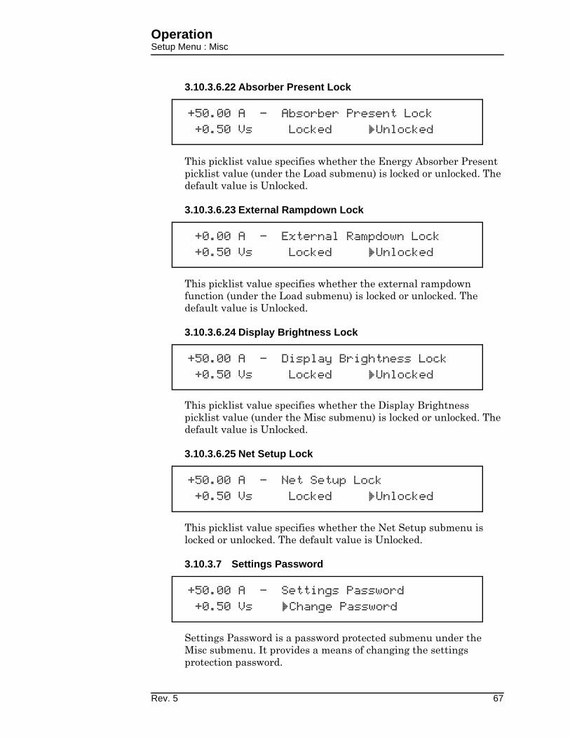
OperationSetup Menu : Misc
3.10.3.6.22 Absorber Present Lock
This picklist value specifies whether the Energy Absorber Present picklist value (under the Load submenu) is locked or unlocked. The default value is Unlocked.
3.10.3.6.23 External Rampdown Lock
This picklist value specifies whether the external rampdown function (under the Load submenu) is locked or unlocked. The default value is Unlocked.
3.10.3.6.24 Display Brightness Lock
This picklist value specifies whether the Display Brightness picklist value (under the Misc submenu) is locked or unlocked. The default value is Unlocked.
3.10.3.6.25 Net Setup Lock
This picklist value specifies whether the Net Setup submenu is locked or unlocked. The default value is Unlocked.
3.10.3.7 Settings Password
Settings Password is a password protected submenu under the Misc submenu. It provides a means of changing the settings protection password.
+50.00 A — Absorber Present Lock+0.50 Vs Locked Unlocked
+0.00 A — External Rampdown Lock+0.50 Vs Locked Unlocked
+50.00 A — Display Brightness Lock+0.50 Vs Locked Unlocked
+50.00 A — Net Setup Lock+0.50 Vs Locked Unlocked
+50.00 A — Settings Password+0.50 Vs Change Password
Rev. 5 67
OperationSetup Submenu : Net Settings
When ENTER is pressed to change the settings protection password, the current password must be correctly entered before a new password can be entered.
Using the keypad, type the current 4-digit (maximum) numeric password and press ENTER. The default password is 1234. If an incorrect password is entered, the Model 430 Programmer beeps and again prompts for the password. Once the password has been correctly entered, the user is prompted for the new password.
Using the keypad, type the new 4-digit (maximum) numeric password and press ENTER. The user is then prompted to re-enter the new password for confirmation.
Using the keypad, again type the new 4-digit (maximum) numeric password and press ENTER. If the second password entry does not match the first password entry, the Model 430 Programmer beeps and the user is prompted again to re-enter the new password. The new password is not accepted until it is confirmed by entering the same password a second time. If ESC is pressed before confirmation is completed, the display returns to the Settings Password submenu, and the current password remains unchanged.
3.10.4 Net Settings Submenu
Selecting the Net Settings submenu allows all currently assigned network settings to be viewed (but not edited). To edit network settings, select the Net Setup submenu.
+50.00 A — Enter Current Password*+0.50 Vs _
+50.00 A — Enter New Password*+0.50 Vs _
+50.00 A — Enter New Password Again*+0.50 Vs _
68 Rev. 5

OperationSetup Submenu : Net Settings
3.10.4.1 Addr Assignment (Present)
This submenu item displays the currently selected method of IP address assignment. The value will either be DHCP or Static. The default value is DHCP, which means that the system IP address, the subnet mask and the gateway IP address are dynamically determined by the network DHCP server.
3.10.4.2 System Name (Present)
This submenu item displays the currently assigned system name (also known as host name or computer name), the name by which the Model 430 Programmer is identified on a network. This setting can only be modified using remote communications (either Ethernet or RS-232); it cannot be edited using the front panel keypad.
3.10.4.3 IP Address (Present)
This submenu item displays the currently assigned system IP address for the Model 430 Programmer. The value in parentheses after the IP address value indicates how the IP address is assigned. DHCP indicates that the value is dynamically assigned by a DHCP server; Static indicates that the value is static, assigned by the Model 430 user. The default value is 0.0.0.0. However, since the default method of IP address assignment is by DHCP server, this value is typically set by the network DHCP server.
3.10.4.4 Subnet Mask (Present)
This submenu item displays the currently assigned subnet mask for the Model 430 Programmer. The value in parentheses after the subnet mask value indicates how the subnet mask is assigned.
+50.00 A — Addr Assignment (Present)+0.50 Vs DHCP
+50.00 A — System Name (Present)+0.50 Vs AMI
+50.00 A — IP Address (Present)+0.50 Vs 0.0.0.0 (DHCP)
+50.00 A — Subnet Mask (Present)+0.50 Vs 0.0.0.0 (DHCP)
Rev. 5 69

OperationSetup Submenu : Net Setup
DHCP indicates that the value is dynamically assigned by a DHCP server; Static indicates that the value is static, assigned by the Model 430 user. The default value is 0.0.0.0. However, since the default method of subnet mask assignment is by DHCP server, this value is typically set by the network DHCP server.
3.10.4.5 Gateway Address (Present)
This submenu item displays the currently assigned gateway IP address for the Model 430 Programmer. The value in parentheses after the gateway IP address value indicates how the gateway IP address is assigned. DHCP indicates that the value is dynamically assigned by a DHCP server; Static indicates that the value is static, assigned by the Model 430 user. The default value is 0.0.0.0. However, since the default method of subnet mask assignment is by DHCP server, this value is typically set by the network DHCP server.
3.10.5 Net Setup Submenu
Selecting the Net Setup submenu allows network settings to be edited (except for the system name, which can only be modified using remote communications). Note also that the system IP address, the subnet mask and the gateway IP address can only be assigned by the user if the currently selected method of IP address assignment is Static; if the currently selected method of IP address assignment is DHCP, then these three values will be set by the network DHCP server.
3.10.5.1 IP Address Assignment
This picklist value specifies method of IP address assignment. The value can be set to either DHCP or Static. If the value is DHCP, then the system IP address, the subnet mask and the gateway IP address are dynamically assigned by the network DHCP server. If the value is Static, then the system IP address, the subnet mask and the gateway IP address are assigned static values by the user. The default value is DHCP.
+50.00 A — Gateway Address (Present)+0.50 Vs 0.0.0.0 (DHCP)
+50.00 A — IP Address Assignment+0.50 Vs DHCP Static
70 Rev. 5
OperationSetup Submenu : Net Setup
Note
If the IP Address Assignment value is changed, the Model 430 Programmer power must be cycled off for at least 15 seconds and then back on to complete the change. The previous value will continue to be used until the Model 430 is restarted.
3.10.5.2 System IP Address
If IP Address Assignment is Static, then the system IP address can be assigned by the user. The default value is 0.0.0.0.
Note
This item is only available in the Net Setup submenu if IP Address Assignment is Static. If IP Address Assignment is DHCP, the system IP address is assigned by the network DHCP server and cannot be assigned by the user.
3.10.5.3 Subnet Mask
If IP Address Assignment is Static, then the subnet mask can be assigned by the user. The default value is 0.0.0.0.
Note
This item is only available in the Net Setup submenu if IP Address Assignment is Static. If IP Address Assignment is DHCP, the subnet mask is assigned by the network DHCP server and cannot be assigned by the user.
3.10.5.4 Gateway IP Address
If IP Address Assignment is Static, then the gateway IP address can be assigned by the user. The default value is 0.0.0.0.
+50.00 A — System IP Address+0.50 Vs 0.0.0.0
+50.00 A — Subnet Mask+0.50 Vs 0.0.0.0
+50.00 A — Gateway IP Address+0.50 Vs 0.0.0.0
Rev. 5 71

OperationExample Setup
Note
This item is only available in the Net Setup submenu if IP Address Assignment is Static. If IP Address Assignment is DHCP, the gateway IP address is assigned by the network DHCP server and cannot be assigned by the user.
3.11 Example Setup
As a precursor to operating a superconducting magnet with the Model 430 Programmer and power supply, all of the setup items should be reviewed and set if necessary with appropriate values for the connected superconducting magnet.
Figure 3-13 (on the next page) shows an example magnet specifications sheet. Several parameters needed to operate the magnet are specified. These values should be entered into the appropriate setup menu of the Model 430 Programmer. For the purposes of this example, the AMI Model 4Q06125PS power supply will be assumed, since rated current for the example magnet is 85.6 A.
72 Rev. 5
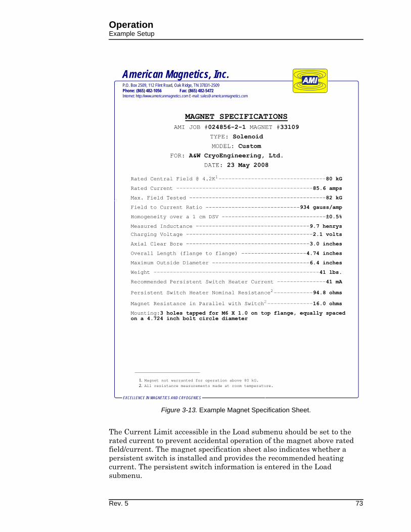
OperationExample Setup
The Current Limit accessible in the Load submenu should be set to the rated current to prevent accidental operation of the magnet above rated field/current. The magnet specification sheet also indicates whether a persistent switch is installed and provides the recommended heating current. The persistent switch information is entered in the Load submenu.
EXCELLENCE IN MAGNETICS AND CRYOGENICS
American Magnetics, Inc.P.O. Box 2509, 112 Flint Road, Oak Ridge, TN 37831-2509
Phone: (865) 482-1056 Fax: (865) 482-5472Internet: http://www.americanmagnetics.com E-mail: [email protected]
AMI JOB # MAGNET #
TYPE:
MODEL:
FOR:
DATE:
Rated Central Field @ 4.2K1---------------------------------
Rated Current ------------------------------------------
Max. Field Tested ------------------------------------------
Field to Current Ratio -----------------------------
Homogeneity over a 1 cm DSV --------------------------------
Measured Inductance -----------------------------------
Charging Voltage ---------------------------------------
Axial Clear Bore --------------------------------------
Overall Length (flange to flange) --------------------
Maximum Outside Diameter ------------------------------
Weight ---------------------------------------------------
Recommended Persistent Switch Heater Current ---------------
Persistent Switch Heater Nominal Resistance2------------
Magnet Resistance in Parallel with Switch2--------------
Mounting:
1. Magnet not warranted for operation above 80 kG.2. All resistance measurements made at room temperature.
Figure 3-13. Example Magnet Specification Sheet.
Rev. 5 73

OperationRamping Functions
If your magnet, Model 430 Programmer, and power supply were purchased as a system from AMI, the setup menus are preset by AMI to match the magnet purchased.
Table 3-5 provides a summary of the Model 430 Programmer setup parameters for this example.
3.12 Ramping Functions
The ramping functions are used to control charging of the superconducting load. The Model 430 Programmer allows piecewise-linear charging profiles
Table 3-5. Example Setup Configuration
Parameter Setting
Select Supply AMI 4Q06125PS
Stability Setting (%) 0.0
Coil Constanta (kG/A)
a. Also referred to as the Field-to-Current Ratio. Obtained by
dividing the rated field by the rated current if not explicitly
stated.
0.934
Current Limit (A) 85.600
PSwitch Installed YES
PSwitch Current (mA) 41.0
PSwitch Heated Time (sec) 20
PSwitch Cooled Time (sec) 20
PSwitch P/S Ramp Rate (A/sec) 10
Enable Quench Detect YES
Energy Absorber Present NO
Voltage Limit (V) 4.100b
b. Value is the 2.1 V charge rate plus allowances for power
lead drop at the rated current.
Ramp Rate (A/sec) 0.2165c
c. Value is obtained by dividing the magnet charging voltage
(V) by the magnet inductance (H).
Magnet Current Rating (A) 85.600
PSwitch Cooling Gain (%) 0.0%
Extern Rampdown Enabled YES
74 Rev. 5

OperationRamping Functions : States and Controls
to be defined and executed (up to 10 segments, each with a unique ramp rate). The basic charging equation for a superconducting magnet is:
where V is the charging voltage (V), L is the magnet inductance (H), and di/dt is the ramp rate (A/s). The relationship may also be defined in terms of a ramp rate in kG/s by the relationship:
where C is the coil constant (or field-to-current ratio) in kG/A, and dB/dt is the ramp rate expressed in kG/s.
A desired ramp rate should be selected by the user and entered into the Model 430 Programmer. A Voltage Limit should also be specified that is greater than or equal to the voltage calculated from the equations above plus energy absorber voltage (if installed) plus power lead voltage drop (usually less than 2 V).
Once the ramp rate and Voltage Limit are specified, the Model 430 Programmer provides two modes of ramping: manual and automatic. Manual ramping will ramp to the Current Limit via manual direction control by the user. Automatic ramping will ramp to the target field/current automatically. Automatic ramping can be thought of as a “next point” operation, whereby the Model 430 determines the appropriate ramp direction based on the present magnet current and the target value.
Note
You may enter up to 10 digits beyond the decimal point within the ramping control menus. These extra digits are maintained in the internal memory of the Model 430 Programmer even though the full precision is not displayed after entry.
3.12.1 Ramping States and Controls
The ramping state may be one of several values as described in Table 3-6.
If the RAMP / PAUSE key is pressed while ramping, the PAUSED mode becomes active. To begin automatic ramping, press the RAMP / PAUSE key to deactivate the PAUSED mode. If manual ramping is desired, use either the INCR. FIELD or DECR. FIELD SHIFT-key for manual control of ramping up or ramping down, respectively.
Voltage limit and ramp rate may be specified from quickly accessible SHIFT-key menus from the front panel keypad1. The settings for Voltage
V L idtd
----=
V LC---- Bd
td------=
Rev. 5 75

OperationRamping Functions : Manual Ramping
Limit and ramp rate(s) are applicable to both manual and automatic ramping.
3.12.2 Manual Ramping
The INCR. FIELD and DECR. FIELD SHIFT-key functions control manual ramping. Manual ramping ramps field/current up or down at the defined ramp rate(s). See section 3.7.4 on page 37 and section 3.7.6 on page 38 for details regarding the use of these SHIFT-key functions.
3.12.3 Automatic Ramping
Automatic ramping differs from manual ramping in that the Model 430 Programmer automatically performs ramping in the appropriate direction to achieve the value of the target field/current setting. To use automatic ramping, enter the target field/current with which ramping is desired1. If ramping is not PAUSED, ramping to the target field/current begins immediately. If ramping is PAUSED, ramping to the target field/current will begin when the RAMP / PAUSE key is pressed to take the Model 430
1. Refer to section 3.7.1 on page 33 and section 3.7.2 on page 36.
Table 3-6. Ramp modes and descriptions.
Mode Description
Ramping Automatic ramping to the target field/currenta is in progress.
HoldingThe target field/current has been achieved and is being maintained.
PausedRamping is suspended at the field/current achieved at the time the PAUSED mode was entered.
ManualRamping is being controlled by the manual control (INCR. FIELD and DECR. FIELD) SHIFT-key functions available on the front panel.
Zeroing Current
RAMP TO ZERO is active, and the Model 430 Programmer is ramping current to 0 A.
Zero CurrentRAMP TO ZERO is still active, and the current is less than 0.1% of Imax.
Heating
Switch
The persistent switch heater has been activated. Ramping is disabled during the persistent switch heating period.
Cooling
Switch
The persistent switch heater has been deactivated. Ramping is disabled during the persistent switch cooling period.
a. The target field/current setting is discussed in section 3.6.2.
1. Refer to section 3.6.2 on page 31.
76 Rev. 5

OperationRamping Functions : Ramping to Zero
Programmer out of PAUSED mode. The ramp rate will be controlled by the preset ramp rate variables as described in section 3.7.1 on page 33.
3.12.4 Ramping to Zero
Pressing the RAMP TO ZERO key activates an immediate ramp to zero field/current. See section 3.6.4 on page 31 for details.
3.12.5 Fine Adjust of Field / Current in Holding Mode
If the target field/current menu is active and the Model 430 Programmer is in HOLDING mode (indicated by a “–” Status Indicator), the fine adjust knob can be used to manipulate the output current. While at the target field/current menu, press SHIFT, followed by FINE ADJUST. This will allow fine adjustment of the field/current (see section 3.4).
When the fine adjust knob is turned the Model 430 Programmer will follow the target current as it is adjusted, at the defined ramp rate for the segment in which it is operating. Adjustment of the current is prevented from exceeding the Current Limit specified in the Load setup menu (see section 3.10.2.4 on page 52). The resolution of the adjustment is 15 digits, which is greater than the resolution of the display.
When the field/current is adjusted to the desired value, press the ENTER key to keep that value as the target field/current. If any other operation is performed before ENTER is pressed, the target field/current value will revert back to what it was before adjustment using the fine adjust knob was initiated, and the current will immediately begin ramping back to that value.
3.13 Persistent Switch Control
The Model 430 Programmer includes an integral persistent switch heater that provides the capability of controlling the persistent mode of the magnet either locally from the front panel of the Model 430 Programmer using the PERSIST. SWITCH CONTROL key1, or remotely through a communications interface. The persistent mode of the magnet is indicated by the MAGNET IN PERSISTENT MODE LED2.
1. Refer to section 3.6.1 on page 29.
2. Refer to section 3.8.2.2 on page 40.
+20.02 A - Target Current (A)+0.20 Vs +20.0239
Rev. 5 77
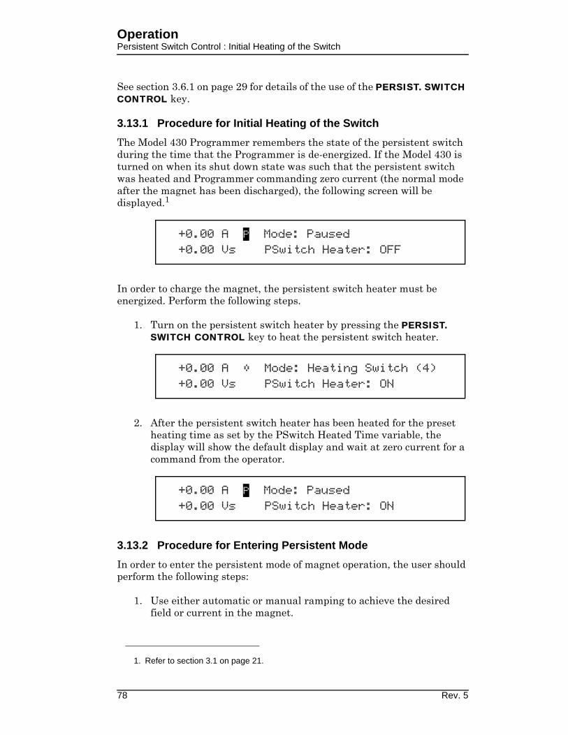
OperationPersistent Switch Control : Initial Heating of the Switch
See section 3.6.1 on page 29 for details of the use of the PERSIST. SWITCH CONTROL key.
3.13.1 Procedure for Initial Heating of the Switch
The Model 430 Programmer remembers the state of the persistent switch during the time that the Programmer is de-energized. If the Model 430 is turned on when its shut down state was such that the persistent switch was heated and Programmer commanding zero current (the normal mode after the magnet has been discharged), the following screen will be displayed.1
In order to charge the magnet, the persistent switch heater must be energized. Perform the following steps.
1. Turn on the persistent switch heater by pressing the PERSIST. SWITCH CONTROL key to heat the persistent switch heater.
2. After the persistent switch heater has been heated for the preset heating time as set by the PSwitch Heated Time variable, the display will show the default display and wait at zero current for a command from the operator.
3.13.2 Procedure for Entering Persistent Mode
In order to enter the persistent mode of magnet operation, the user should perform the following steps:
1. Use either automatic or manual ramping to achieve the desired field or current in the magnet.
1. Refer to section 3.1 on page 21.
+0.00 A P Mode: Paused+0.00 Vs PSwitch Heater: OFF
+0.00 A Mode: Heating Switch (4)+0.00 Vs PSwitch Heater: ON
+0.00 A P Mode: Paused+0.00 Vs PSwitch Heater: ON
78 Rev. 5

OperationPersistent Switch Control : Entering Persistent Mode
2. The Model 430 Programmer must be in either the HOLDING or PAUSED mode at the target field or current.
3. The Model 430 Programmer must be at the default field/current display.1
4. Press the PERSIST. SWITCH CONTROL key to turn off the persistent switch heater current and automatically ramp the power supply to zero current:
a. After the PERSIST. SWITCH CONTROL key is pressed, the Model 430 Programmer requests that the ENTER key be pressed as a confirmation that the magnet should be placed in persistent mode.2
b. When ENTER is pressed, the persistent switch is cooled for the preset persistent switch cooling time (set by the PSwitch Cooled Time variable3). The display indicates that the persistent switch is being cooled and indicates the number of seconds (4 in this example) remaining in the cooling cycle.
c. When the cooled time is complete, the green MAGNET IN PERSISTENT MODE LED will illuminate4 and the power supply will ramp to zero at the PSw P/S Ramp Rate value5.
1. Refer to section 3.2.1 on page 23.
2. Pressing the ESCape key will terminate the command and return the Model 430
Programmer to the default screen.
3. Refer to section 3.10.2.10 on page 56.
4. The threshold for this LED is 100 mA of magnet current.
5. Refer to section 3.10.2.11 on page 56.
+50.00 A - Press ENTER to begin+3.50 Vs Persistent Mode
+50.00 A Mode: Cooling Switch (4)+3.50 Vs PSwitch Heater: OFF
+42.89 A Mode: Power Supply ramping+3.38 Vs to zero current
Rev. 5 79
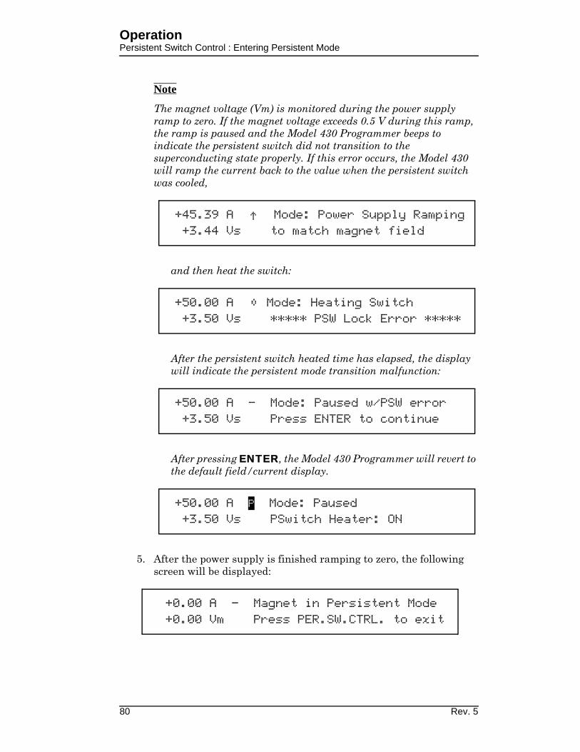
OperationPersistent Switch Control : Entering Persistent Mode
Note
The magnet voltage (Vm) is monitored during the power supply ramp to zero. If the magnet voltage exceeds 0.5 V during this ramp, the ramp is paused and the Model 430 Programmer beeps to indicate the persistent switch did not transition to the superconducting state properly. If this error occurs, the Model 430 will ramp the current back to the value when the persistent switch was cooled,
and then heat the switch:
After the persistent switch heated time has elapsed, the display will indicate the persistent mode transition malfunction:
After pressing ENTER, the Model 430 Programmer will revert to the default field/current display.
5. After the power supply is finished ramping to zero, the following screen will be displayed:
+45.39 A Mode: Power Supply Ramping+3.44 Vs to match magnet field
+50.00 A Mode: Heating Switch+3.50 Vs ***** PSW Lock Error *****
+50.00 A - Mode: Paused w/PSW error+3.50 Vs Press ENTER to continue
+50.00 A P Mode: Paused+3.50 Vs PSwitch Heater: ON
+0.00 A - Magnet in Persistent Mode+0.00 Vm Press PER.SW.CTRL. to exit
80 Rev. 5

OperationPersistent Switch Control : Exiting Persistent Mode
Note
If desired, press the ESC key return the Model 430 Programmer to the default display.
Note
Refer to section 3.6.2 on page 31 for the procedure to display the magnet current that was established when the persistent switch was cooled.
6. If desired, the power supply system can be de-energized. Turn the power supply off first followed in a few seconds by the Model 430 Programmer.
Note
The Model 430 Programmer will store the state of the magnet in memory and assist the user in exiting the persistent mode when the Model 430 Programmer is next turned on (discussed in the section to follow).
3.13.3 Procedure for Exiting Persistent Mode
To exit the persistent mode of magnet operation, the user should perform the following steps:
1. If the Model 430 Programmer has not been powered off since the magnet was placed in persistent mode, proceed to step 3.
2. If the Model 430 Programmer has been powered off since the magnet was placed in persistent mode, complete the following steps a. and b. before proceeding to step 3.
a. Energize the Model 430 and wait for the prompt on the Model 430 display and then energize the power supply.
After the power supply has been on for a few seconds, press ENTER to clear the Model 430 screen prompt.
+0.00 A - Mode: Zero Current+0.00 Vm PSwitch Heater: OFF
+0.00 A P Turn on power supply+0.00 Vs Press ENTER to continue
Rev. 5 81

OperationPersistent Switch Control : Exiting Persistent Mode
b. When ENTER is pressed, the display will indicate that the magnet was in persistent mode1 when the Model 430 Programmer was turned off (and display the magnet current that was established when the persistent switch was cooled).
3. Press PERSIST. SWITCH CONTROL and the Model 430 display prompts with:
Note
Should the user desire not to exit persistent mode, press ESC to return to the default field/current display. If the PERSIST. SWITCH CONTROL key is later pressed, the Model 430 Programmer will execute steps 4 through 7, below.
Note
If persistent mode is not exited and it is later desired to display the magnet current that was established when the persistent switch was cooled, refer to section 3.6.2 on page 31 for the procedure.
4. When ENTER is pressed, the power supply is ramped to the current that was flowing in the magnet at the time the persistent mode was entered. The power supply will ramp at the PSw P/S Ramp Rate value2.
1. The MAGNET IN PERSISTENT MODE LED will also be illuminated.
2. Refer to section 3.10.2.11 on page 56.
Magnet in Persistent Mode (13.5A). PressPERSIST SWITCH CONTROL to exit Per. Mode
+0.00 A P Press ENTER to exit+0.00 Vs Persistent Mode
+11.72 A Mode: Power Supply ramping+0.73 Vs to magnet current
82 Rev. 5

OperationPersistent Switch Control : Exiting Persistent Mode
5. The persistent switch heater is heated for the preset heating time as set by the PSwitch Heated Time variable1.
Note
The magnet voltage (Vm) is monitored during switch heating. If the voltage is greater than, 0.5 V, the Model 430 Programmer will beep and display a message to indicate a mismatch between the magnet current and power supply current:
This mismatch in current indicates the magnet current (and therefore the field) has decayed significantly during the time the magnet was in persistent mode. Since this is not a critical error2, after 15 seconds the screen will change back to the default display:
6. After the Model 430 Programmer has completed this persistent switch heating operation, the display reads:
1. Refer to section 3.10.2.9 on page 55. The (4) in the display indicates the number of
seconds remaining in the heating cycle (4 in this example).
2. This current mismatch could be indicative of a problem with the magnet persistent
joints.
+50.00 A Mode: Heating Switch (4)+3.50 Vs PSwitch Heater: ON
+50.00 A Mode: Heating Switch (4)+3.50 Vs *** Current Mismatch ***
+50.00 A P Mode: Paused+3.50 Vs PSwitch Heater: ON
+50.00 A P Mode: Magnet in Driven Mode+3.50 Vs Press ENTER to continue
Rev. 5 83

OperationPersistent Switch Control : Exiting Persistent Mode
7. After ENTER is pressed, the default field/current status screen is displayed with the power supply in the pause mode:
3.13.4 Toggling the State of the Persistent Switch Heater
The state of the persistent switch can be toggled by pressing SHIFT and then the PERSIST. SWITCH CONTROL key. By toggling the state of the heater in this manner, there will be no power supply ramping or other automatic functions.
3.13.4.1 Entering Persistent Mode without altering the power supply current output
1. Place the Model 430 Programmer in the HOLDING or PAUSED mode at the desired field or current.
2. Press the SHIFT and then the PERSIST. SWITCH CONTROL key to turn off the persistent switch heater current. Note that the Model 430 Programmer will enter the COOLING SWITCH mode and disallow any ramping during the switch cooling period.
3. If magnet current is greater than 100 mA when the switch heater current is turned off, the MAGNET IN PERSISTENT MODE LED will illuminate.
3.13.4.2 Exiting Persistent Mode without altering the power sup-ply current output
Caution
To avoid damage to the magnet or triggering protection circuits on the magnet, the current in the power supply should match the current that was flowing in the magnet when the persistent mode was entered.
Note
For the procedure to display the magnet current that was established when the persistent switch was cooled, refer to section 3.6.2 on page 31.
1. Place the Model 430 Programmer in the HOLDING or PAUSED mode at the desired field or current.
+50.00 A P Mode: Paused+3.50 Vs PSwitch Heater: ON
84 Rev. 5

OperationRamping Functions Example
2. Press the SHIFT and then the PERSIST. SWITCH CONTROL key to turn on the persistent switch heater current. Note that the Model 430 Programmer will enter the HEATING SWITCH mode and disallow any ramping during the switch heating period.
3. At the end of the switch heating period, the MAGNET IN PERSISTENT MODE LED will be turned off and the Model 430 Programmer will be in the PAUSED mode.
3.14 Ramping Functions Example
As an example of ramping to two target field/current settings, refer to Figure 3-14 below. Each step is labeled as 1 through 8 in Figure 3-14. The Model 430 Programmer, for the purposes of the example, is assumed to be in the PAUSED mode at 0 A at the beginning of the ramping example.
Point 1. The current is 0 A and the Model 430 Programmer is in the PAUSED mode. The user sets the target field/current to -40.000 A. The RAMP / PAUSE key is pressed so that the PAUSED mode is no longer active and the Model 430 begins ramping current.
Point 2. The target field/current setting of -40.000 A is achieved and the Model 430 Programmer switches to HOLDING mode.
Point 3. The user changes the ramp rate setting. The user also sets a new value of +40.000 A for the target field/current. As soon as the new target
Figure 3-14. Ramping to Two Different Target Field/Current Settings.
Rev. 5 85

OperationQuench Detection
field/current is entered, the Model 430 Programmer automatically begins ramping at the specified ramp rate.
Point 4. The user presses the RAMP / PAUSE key at a current of 25.15 A and the PAUSED mode is activated. The Model 430 Programmer maintains the current in the PAUSED mode.
Point 5. The user presses the RAMP / PAUSE key once again to resume ramping.
Point 6. The target field/current setting of +40.000 A is achieved and the Model 430 Programmer switches to HOLDING mode. At this point the user deactivates the persistent switch heater by pressing the PERSIST. SWITCH CONTROL key, which removes the magnet from the circuit.
Point 6a. The dashed line between point 6a and 6b is the rapid ramping down of the power supply current which automatically happens after the PSwitch Cooled Time has elapsed. Note that the magnet current remains at the Point 6 value when the magnet was placed in persistent mode.
Point 6c. The user presses the PERSIST. SWITCH CONTROL key which rapidly ramps the power supply output to the current that is flowing in the magnet. The power supply matches the magnet current at point 6d.
Point 7. The user again increases the ramp rate and presses the RAMP TO ZERO key to begin ramping to zero current. The Model 430 Programmer automatically ramps the current to 0 A.
Point 8. The Model 430 Programmer switches to ZERO CURRENT mode at 0 A current when achieved and holds at this current until further commands are issued by the user.
3.15 Quench Detection
The Model 430 Programmer continuously monitors the superconducting magnet load and can automatically detect a field/current quench condition. If a quench is detected, the MAGNET QUENCH LED will be illuminated and the display will appear as shown below. When a quench is detected, the Model 430 automatically sets the power supply output voltage to zero, provides a quench output signal (dry contacts) to the rear panel Quench I/O connector (see page 149 of the Appendix for the connector pinout), and will not respond to further input until the RESET QUENCH SHIFT-key is
86 Rev. 5

OperationQuench Detection : External Detection
used to clear the quench detect condition, or until the quench condition is cleared by a remote command.
If the RESET QUENCH key has been locked1, the user will be asked to enter the password to clear the quench. The entry of this password will not unlock this reset quench feature, but will only reset the current quench event so operation may resume. Enter the password followed by the ENTER key to reset the quench and continue.
When the RESET QUENCH SHIFT-key is used to clear the quench condition or a remote clear command is issued, the Model 430 Programmer will automatically enter the PAUSED mode and will attempt to maintain the current present at the point the quench condition was cleared.
3.15.1 External Quench Detection
The rear panel Quench I/O connector provides pins for external quench input (contact closure — see page 149 of the Appendix for the connector pinout). If the quench input is asserted, then the Model 430 Programmer interprets this input as indication of a quench condition and the Model 430 automatically sets the power supply output voltage to zero and will not respond to further input until the RESET QUENCH SHIFT-key is used to clear the quench detect condition, or until the quench condition is cleared by a remote command. The rear panel input cannot be disabled; however, it may be left disconnected without the possibility of a generating a false quench condition.
Note
If the external quench detection circuit continues to assert the quench detection input of the Model 430 Programmer, the RESET QUENCH SHIFT-key will be unable to clear the quench condition.
1. Refer to section 3.10.3.6.8 on page 63.
+44.36 A Quench Detect @ +80.56 A +0.00 Vs PSwitch Heater: ON
+44.36 A Enter Password* +0.00 Vs _
Rev. 5 87

OperationQuench Detection : Disabling Internal Detection
3.15.2 Disabling Internal Quench Detection
The internal quench detection feature may be disabled in the Load submenu1. However, the rear panel Quench I/O connector output remains active.
If the internal quench detection feature is disabled, the Model 430 Programmer attempts to limit the error between the commanded current and the present current to a value that will not result in excessive voltages being introduced across the magnet terminals. Under most operating conditions this will not damage any internal protection circuits of the magnet. If an actual quench condition occurs, the Model 430 will follow the magnet current to zero unless the user intervenes. If the rear panel Quench I/O connector is asserted, the Model 430 will force the power supply output to zero volts regardless of whether the internal quench detection is enabled or disabled.
In the event that the persistent switch becomes normal without user or remote activation of the switch heater control, the Model 430 Programmer will match the magnet current and attempt to stabilize the load if the internal quench detection feature is disabled. If the internal quench detection feature is enabled, then this event will generally trigger the quench detection logic if a difference exists between the magnet current and the real-time setpoint current of the Model 430.
3.16 External Rampdown
This feature2 is useful in any application requiring magnet rampdown in response to an event that can be represented by the closure of a pair of electrical contacts3.
A user input for initiating external rampdown is provided on the rear panel of the Model 430 Programmer. The process is started by shorting, for at least 10 milli-seconds, the input connections through closure of user-supplied external contacts. Once triggered, rampdown of the magnetic field of the magnet is initiated. Operator intervention (such as Ramp/Pause, ESC, etc.) is inhibited until rampdown is completed and the external rampdown signal is cleared.
The external rampdown feature is ideally suited for use with AMI’s Model 135 Liquid Helium Level Monitor. The Model 135 has externally accessible normally-open relay contacts that close whenever helium level drops below
1. Refer to section 3.10.2.13 on page 57.
2. When enabled. Refer to section 3.10.2.15 on page 58.
3. Refer to section A.5.2 on page 150. The contact closure time must be at least 10
milli-seconds to ensure it doesn’t fall between the sampling points of the Model 430
Programmer.
88 Rev. 5

OperationExternal Rampdown : External Rampdown while in Persistent Mode
a preset level. When appropriately connected to the Model 430 Programmer, these contacts can signal the Model 430 to safely and automatically ramp the magnet field to zero, thereby preventing a magnet quench due to low helium level in the system.
3.16.1 External Rampdown while in Persistent Mode
The following steps and associated screen displays describe the process that occurs after external rampdown is initiated while the magnet is in persistent mode:
1. The Model 430 Programmer first ramps the power supply to the magnet current.
2. Once the power supply is at the magnet current, the FIELD AT TARGET LED will light and the unit will momentarily “hold”:
3. Following a short “hold”, the persistent switch will be heated to place the power supply in control of magnet current:
4. After heating (turning off) the persistent switch, the MAGNET IN PERSISTENT MODE LED extinguishes, and rampdown begins. The FIELD AT TARGET LED extinguishes.
5. After rampdown, the following will display:
+3.92 A Mode: Ramping+0.17 Vs PSwitch Heater: OFF
+50.00 A - Mode: Holding+2.11 Vs PSwitch Heater: OFF
+50.00 A Mode: Heating Switch (4)+2.11 Vs PSwitch Heater: ON
+48.85 A Mode: Zeroing Current+1.89 Vs PSwitch Heater: ON
+0.00 A - Ext. Rampdown completed-0.00 Vs Press ENTER to continue
Rev. 5 89

OperationExternal Rampdown : External Rampdown while not in Persistent Mode
Note
The external rampdown signal MUST be cleared before pressing ENTER will yield a response. Further operator control is inhibited until the external rampdown signal is cleared.
6. Once the external signal has been cleared, ENTER can be pressed. User control will be re-established and the operator can continue manual operation of the system. The following will be displayed after pressing ENTER:
3.16.2 External Rampdown while not in Persistent Mode
When external rampdown is initiated with the magnet not in PERSISTENT mode, the persistent switch is either off or not installed so there is no need for persistent switch heating. The power supply is already at (and in control of) the magnet current, so the Model 430 Programmer executes an ordinary rampdown:
1. The rampdown begins immediately at the ZEROING CURRENT mode described on page 89 (step 4 of section 3.16.1, “External Rampdown while in Persistent Mode”):
2. The sequence continues as described for the magnet in persistent mode (section 3.16.1, steps 5 through 6).
Note
After rampdown, the external rampdown signal MUST be cleared before continuing. Further operator control is inhibited until the external rampdown signal is cleared.
3.17 Summary of Operational Limits and Default Settings
Table 3-7 provides a summary of the operational limits and the default setting for all Model 430 Programmer parameters. If the user attempts to enter a value outside of the limits, the Model 430 Programmer will beep once and revert to the previous setting.
+0.00 A - Mode: Zero Current+0.00 Vs PSwitch Heater: ON
+48.85 A Mode: Zeroing Current+1.89 Vs PSwitch Heater: ON
90 Rev. 5

OperationSummary of Operational Limits
References to the specifications indicate that the absolute limit is determined by the specific configuration of the Model 430 Programmer purchased.
Table 3-7. Summary of Model 430 Programmer Limits and Defaults
Model 430 Setting (Units) Absolute Limits Default Settinga
a. Unless preset by factory.
Min Output Voltage (V) 0.000 to -20.000 -6.000
Max Output Voltage (V) 0.001 to +20.000 6.000
Min Output Current (A) see table on page 8 -125.000
Max Output Current (A) see table on page 8 125.000
V-V Mode Input Range (V) -10.000 to +10.000 -10.000 to +10.000
Stability Setting (%) 0.0 to 100.0 0.0
Coil Constant (kG/A) 0.001 to 999.99999 1.0
PSwitch Current (mA) 0.0 to 125.0 10.0
PSwitch Heated Time (sec) 5 to 120 20
PSwitch Cooled Time (sec) 5 to 3600 20
PSwitch Power Supply Ramp Rate (A/sec)
same as min and max ramp
(see table on page 8)10
PSwitch Cooling Gain 0.0 to 100.0 0.0
Magnet Current Rating (A) +/-0.001 to +/-
9999.9999999999
80.000
Current Limit (A)≥ Min Output Current and
≤ Max Output Current80.000
Display Brightness (%) 25, 50, 75, 100 100
Voltage Limit (V)≥ 0.001 and
≤ Max Output Voltage2.000
Ramp Rate (A/sec) see table on page 8 0.100
Target Current (A) ≤ Current Limit 5.000
Rev. 5 91

OperationSummary of Operational Limits
92 Rev. 5
4 Remote Interface Reference
The Model 430 Programmer provides both RS-232 and Ethernet interfaces as standard features. The serial and Ethernet interfaces may operated simultaneously. Separate output buffers are also provided for the serial and Ethernet return data. However, for optimal performance and simplicity of programming, AMI normally recommends limiting operation to one interface. An exception to this recommendation would be using the serial port as a debugging aid during programming of the Ethernet port (or vice-versa), which can prove to be a useful resource.
4.1 SCPI Command Summary
The following manual conventions are used for SCPI (Standard Commands for Programmable Instruments) syntax for the remote interface commands:
• Braces { } enclose valid parameter choices.
• A vertical bar | separates multiple choices for each parameter.
• Triangle brackets < > indicate that you must supply a value.
• Parentheses ( ) within < > indicate alternative units are available.
For example, the command PSwitch {0|1} indicates that the command PSwitch has two parameter options: 0 or 1. Refer to the detailed description of each command for information regarding specific parameter choices and their meanings. Capitalized portions of the commands indicate acceptable abbreviations. Default settings are shown in bold.
(see page 108 for more information)
*IDN?*RST*TST?<Ctrl-C>
SYSTem:LOCalSYSTem:REMoteSYSTem:TIME?SYSTem:TIME:SET <date(mm/dd/yyyy) time(hh:mm:ss)>SYSTem:ERRor?
System-Related Commands
Rev. 5 93
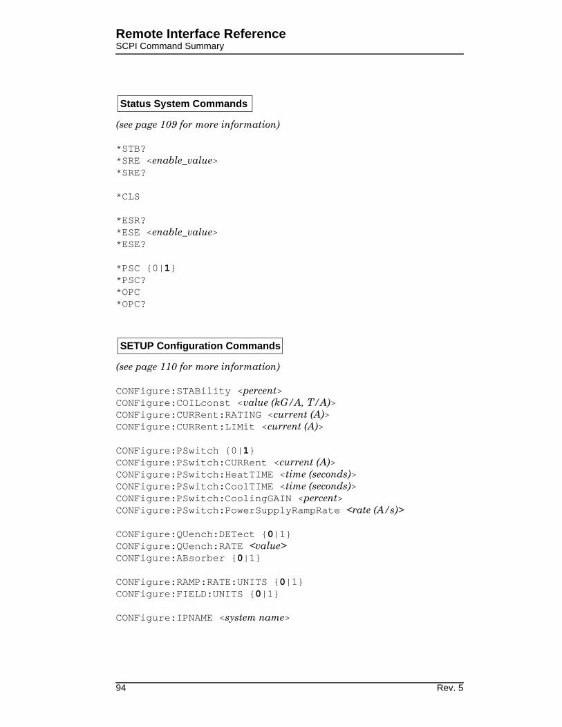
Remote Interface ReferenceSCPI Command Summary
(see page 109 for more information)
*STB?*SRE <enable_value>*SRE?
*CLS
*ESR?*ESE <enable_value>*ESE?
*PSC {0|1}*PSC?*OPC*OPC?
(see page 110 for more information)
CONFigure:STABility <percent>CONFigure:COILconst <value (kG/A, T/A)>CONFigure:CURRent:RATING <current (A)>CONFigure:CURRent:LIMit <current (A)>
CONFigure:PSwitch {0|1}CONFigure:PSwitch:CURRent <current (A)>CONFigure:PSwitch:HeatTIME <time (seconds)>CONFigure:PSwitch:CoolTIME <time (seconds)>CONFigure:PSwitch:CoolingGAIN <percent>CONFigure:PSwitch:PowerSupplyRampRate <rate (A/s)>
CONFigure:QUench:DETect {0|1}CONFigure:QUench:RATE <value>CONFigure:ABsorber {0|1}
CONFigure:RAMP:RATE:UNITS {0|1}CONFigure:FIELD:UNITS {0|1}
CONFigure:IPNAME <system name>
Status System Commands
SETUP Configuration Commands
94 Rev. 5

Remote Interface ReferenceSCPI Command Summary
(see page 110 for more information)
SUPPly:VOLTage:MINimum?SUPPly:VOLTage:MAXimum?
SUPPly:CURRent:MINimum?SUPPly:CURRent:MAXimum?
SUPPly:TYPE?SUPPly:MODE?
STABility?COILconst?CURRent:LIMit?CURRent:RATING?
PSwitch:CURRent?PSwitch:HeatTIME?PSwitch:CoolTIME?PSwitch:PowerSupplyRampRate?PSwitch:AUTODetect?PSwitch:CoolingGAIN?PSwitch:INSTalled?
QUench:DETect?QUench:RATE?ABsorber?
RAMP:RATE:UNITS?FIELD:UNITS?
IPNAME?
(see page 115 for more information)
CONFigure:LOCK:PSwitch:CONTRol {0|1}CONFigure:LOCK:TARGet {0|1}CONFigure:LOCK:RAMP-PAUSE {0|1}CONFigure:LOCK:RAMPrate {0|1}CONFigure:LOCK:ZEROfield {0|1}
SETUP Configuration Queries
Protection Configuration Commands
Rev. 5 95

Remote Interface ReferenceSCPI Command Summary
CONFigure:LOCK:RAMPDown {0|1}CONFigure:LOCK:SUPPly {0|1}CONFigure:LOCK:VOLTage:LIMit {0|1}CONFigure:LOCK:QUench:RESet {0|1}CONFigure:LOCK:INCR-DECR {0|1}CONFigure:LOCK:FIELD-CURRent {0|1}CONFigure:LOCK:FIELD:UNITS {0|1}CONFigure:LOCK:STABility {0|1}CONFigure:LOCK:VOLTage:VS-VM {0|1}CONFigure:LOCK:VOLTMeter {0|1}CONFigure:LOCK:FINEadjust {0|1}CONFigure:LOCK:COILconst {0|1}CONFigure:LOCK:CURRent:LIMit {0|1}CONFigure:LOCK:CURRent:RATING {0:1}CONFigure:LOCK:PSwitch:SETtings {0|1}CONFigure:LOCK:QUench:DETect {0|1}CONFigure:LOCK:QUench:RATE {0|1}CONFigure:LOCK:ABsorber {0|1}CONFigure:LOCK:BRIGHTness {0|1}CONFigure:LOCK:NETsetup {0|1}
(see page 115 for more information)
LOCK:PSwitch:CONTRol?LOCK:TARGet?LOCK:RAMP-PAUSE?LOCK:ZEROfield?LOCK:RAMPrate?LOCK:RAMPDown?LOCK:SUPPly?LOCK:VOLTage:LIMit?LOCK:QUench:RESet?LOCK:INCR-DECR?LOCK:FIELD-CURRent?LOCK:FIELD:UNITS?LOCK:STABility?LOCK:VOLTage:VS-VM?LOCK:VOLTMeter?LOCK:FINEadjust?LOCK:COILconst?LOCK:CURRent:LIMit?LOCK:CURRent:RATING?LOCK:PSwitch:SETtings?LOCK:QUench:DETect?LOCK:QUench:RATE?
Protection Configuration Queries
96 Rev. 5

Remote Interface ReferenceSCPI Command Summary
LOCK:ABsorber?LOCK:BRIGHTness?LOCK:NETsetup?
Rev. 5 97

Remote Interface ReferenceSCPI Command Summary
(see page page 120 for more information)
CONFigure:VOLTage:LIMit <voltage (V)>
CONFigure:CURRent:TARGet <current (A)>CONFigure:FIELD:TARGet <field (kG, T)>
CONFigure:RAMP:RATE:CURRent <segment>,<rate (A/s, A/min)>,<upper bound (A)>
CONFigure:RAMP:RATE:FIELD <segment>,<rate (kG/s, kG/min, T/s, T/min)>,<upper bound (kG, T)>
CONFigure:RAMP:RATE:SEGments <value>
CONFigure:RAMP:RATE:SEGments <# segments>RAMP:RATE:SEGments?CONFigure:RAMPDown:ENABle {0|1}CONFigure:RAMPDown:RATE:SEGments <# segments>CONFigure:RAMPDown:RATE:CURRent <segment>,<rate (A/s, A/
min)>, <upper bound (A)>CONFigure:RAMPDown:RATE:FIELD <segment>,<rate (kG/s, kG/min,
T/s, T/min)>, <upper bound (Kg, T)>
RAMPDown:ENABle?RAMPDown:RATE:SEGments?RAMPDown:RATE:CURRent: <segment>?RAMPDown:RATE:FIELD: <segment>?
VOLTage:LIMit?
CURRent:TARGet?FIELD:TARGet?
RAMP:RATE:CURRent:<segment>?RAMP:RATE:FIELD:<segment>?
VOLTage:MAGnet?VOLTage:SUPPly?CURRent:MAGnet?CURRent:SUPPly?FIELD:MAGnet?INDuctance?
Ramp Configuration Commands and Queries
98 Rev. 5

Remote Interface ReferenceSCPI Command Summary
(see page 124 for more information)
RAMPPAUSEINCRDECRZERO
STATE?
(see page 125 for more information)
PSwitch {0|1}PSwitch?PERSistent?
(see page 126 for more information)
QUench {0|1}QUench?Quench:COUNT?
(see page 126 for more information)
RAMPDownFile?RAMPDownBackup?RAMPDown:COUNT?
(see page 128 for more information)
Ramping State Commands and Queries
Switch Heater Commands and Queries
Quench State Control and Queries
Rampdown State Control and Queries
Trigger Control and Queries
Rev. 5 99

Remote Interface ReferenceSCPI Introduction
*ETE <enable_value>*ETE?*TRG
4.2 Programming Overview
The Model 430 Programmer conforms to the SCPI (Standard Commands for Programmable Instruments) IEEE standard. The SCPI standard is an ASCII-based specification designed to provide a consistent command structure for instruments from various manufacturers.
The Model 430 Programmer also implements a status system for monitoring the state of the Model 430 through the Standard Event and Status Byte registers.
4.2.1 SCPI Language Introduction
SCPI commands conform to a tree structure where commands are grouped according to common keywords. For example, commands which set a Model 430 Programmer setup or operating parameter begin with the keyword CONFigure. The keywords are shown in upper case and lower case to indicate acceptable abbreviations. For the example keyword CONFigure, the user may send either the abbreviated form of CONF, or the entire keyword CONFIGURE. Any other form of the keyword is illegal and will generate an error.
Many commands also require multiple keywords to traverse the tree structure of the entire Model 430 Programmer command set. For example, commands associated with a current setting require the prefix of CONFigure:CURRent. Note that a colon ( : ) separates the keywords. No spaces are allowed before or after the colon. Parameters must be separated from the command keyword(s) by at least one space.
4.2.2 SCPI Status System
The Model 430 Programmer status system reports various conditions of the instrument in two registers groups shown in Figure 4-1. The register groups consist of a condition or event register, and an enable register which controls the actions of specific bits within the condition or event registers
A condition register continuously monitors the state of the instrument. The bits of a condition register are updated in real time. A condition register is read-only and is not cleared when you read the register. A query of a condition register returns a decimal value in the appropriate output buffer which corresponds to the binary-weighted sum of all bits set in the register.
100 Rev. 5

Remote Interface ReferenceSCPI Status System
An event register latches various events. Events are not buffered, therefore once a bit is set in the event register, further occurrences of that event are ignored. Once a bit is set in an event register, the bit remains set until the register is read (*ESR?) or a *CLS (clear status) command is issued. A query of an event register returns a decimal value in the appropriate output buffer which corresponds to the binary-weighted sum of all bits set in the register.
An enable register (or bitmask) defines which bits in an event register are reported to the Status Byte register group. An enable register can be both written and queried. The *CLS (clear status) command does not clear an enable register. To enable or disable bits in an enable register, write a decimal value which corresponds to the binary-weighted sum of the bits you wish reported to the Status Byte register.
4.2.2.1 Status Byte Register
The Status Byte register group reports conditions from the Standard Event register or output buffers. Data in the output buffer is immediately reported in the “Serial Message Available” bit (bit 3). Clearing a bit in the Standard Event register will update the corresponding bit in the Status Byte register, according to the Standard Event enable register. Reading the pending
0
1
2
3
4
5
6
7
<1>
<2>
<4>
<8>
<16>
<32>
N/A
<128>
*SRE <value>*SRE?
Serial Poll*STB?
C EN
Summary Bit
"OR"
Status Byte Register
0
1
2
3
4
5
6
7
<1>
<2>
<4>
<8>
<16>
<32>
<64>
<128>
*ESE <value>*ESE?
*ESR?
EV EN
"OR"
Standard Event Register
Operation Complete
Query Error
Device Error
Execution Error
Command Error
Power On
Quench Condition
Serial Output Buffer
NOTES:C = Condition RegisterEV = Event RegisterEN = Enable Register
Figure 4-1. The Model 430 Programmer Status System.
Rev. 5 101

Remote Interface ReferenceSCPI Status System
messages in the output buffers will clear the appropriate “Message Available” bit. The bit definitions for the Status Byte register are defined in Table 4-1.
Bit 2 of the Status Byte register, indicating a quench condition, remains set until the quench condition is cleared via the front panel or by remote command. Bits 3 and 4 remain set until all data has been read from the respective output buffer.
The Status Byte condition register is cleared when:
• A *CLS command is executed.
• The Standard Event register is read (only bit 5 of the Status Byte register is cleared).
• The indicated condition no longer exists.
The Status Byte enable register is cleared when:
• The *SRE 0 command is executed.
• The power is turned off and then back on, and the Model 430 Programmer was configured for *PSC 1 (power-on status clear). The enable register setting is persistent if the Model 430 Programmer is configured for *PSC 0 (no status clear on power-on).
Table 4-1. Bit Definitions for the Status Byte Register
Bit NumberDecimal
Value Definition
0 Not Used 1 Always “0”.
1 Not Used 2 Always “0”.
2 Quench Condition 4 The Model 430 has detected a quench.
3 Serial Message Available
8 The serial output buffer contains unread data.
4 Not Used 16 Always “0”.
5 Standard Event 32 One or more enabled bits are set in the Standard Event register.
6 Status Byte Summary
64 One or more enabled bits are set in the Status Byte register.
7 Not Used 128 Always “0”.
102 Rev. 5

Remote Interface ReferenceSCPI Status System
4.2.2.2 Reading the Status Byte using *STB?
The *STB? returns the contents of the Status Byte register, but it is processed in the command queue like any other command. The *STB? command does not clear bit 6 of the Status Byte register.
4.2.2.3 Using the Message Available Bit(s)
The “Message Available” bits (bits 3 or 4) of the Status Byte register can be used to determine when data is available to read into your host computer. The Model 430 Programmer clears the “Message Available” bits only after all data has been read from the output buffer(s).
The “Message Available” bits of the Status Byte register are useful for determining if queries have executed; however, they are not useful alone for determining if commands have completed execution, since commands do not provide return data.
4.2.3 Standard Event Register
The Standard Event register group reports a power-on condition, various error conditions, and indicates when an operation has completed. Any or all of the Standard Events can be reported to the Status Byte register by enabling the corresponding bit(s) in the Standard Event enable register (see Figure 4-1). To set the Standard Event enable register, write a binary-weighted decimal value using the *ESE <value> command.
The bit definitions for the Standard Event register are provided in Table 4-2. To query the Model 430 Programmer for the details of a reported error in the Standard Event register, use the SYSTem:ERRor? query. See section 4.6 for a complete discussion of the error buffer and messages.
The Standard Event register is cleared when:
• The *CLS (clear status) command is executed.
• The Standard Event register is queried using the *ESR? command.
The Standard Event enable register is cleared when:
• The *ESE 0 command is executed.
• The power is turned off and then back on, and the Model 430 Programmer was configured for *PSC 1 (power-on status clear). The
Rev. 5 103
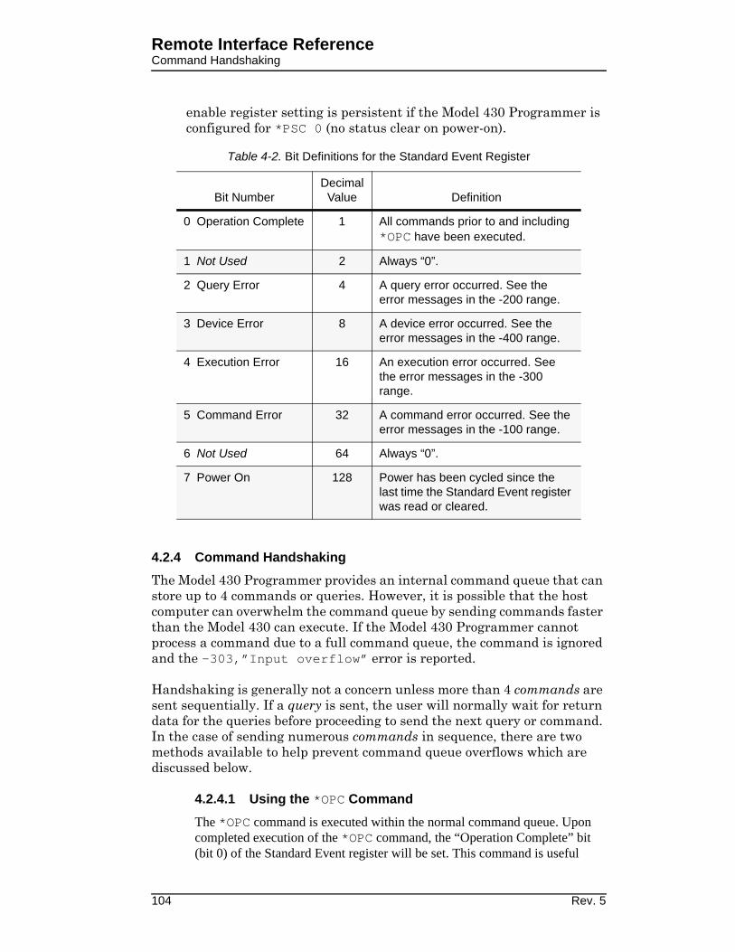
Remote Interface ReferenceCommand Handshaking
enable register setting is persistent if the Model 430 Programmer is configured for *PSC 0 (no status clear on power-on).
4.2.4 Command Handshaking
The Model 430 Programmer provides an internal command queue that can store up to 4 commands or queries. However, it is possible that the host computer can overwhelm the command queue by sending commands faster than the Model 430 can execute. If the Model 430 Programmer cannot process a command due to a full command queue, the command is ignored and the -303,”Input overflow” error is reported.
Handshaking is generally not a concern unless more than 4 commands are sent sequentially. If a query is sent, the user will normally wait for return data for the queries before proceeding to send the next query or command. In the case of sending numerous commands in sequence, there are two methods available to help prevent command queue overflows which are discussed below.
4.2.4.1 Using the *OPC Command
The *OPC command is executed within the normal command queue. Upon completed execution of the *OPC command, the “Operation Complete” bit (bit 0) of the Standard Event register will be set. This command is useful
Table 4-2. Bit Definitions for the Standard Event Register
Bit NumberDecimal
Value Definition
0 Operation Complete 1 All commands prior to and including
*OPC have been executed.
1 Not Used 2 Always “0”.
2 Query Error 4 A query error occurred. See the error messages in the -200 range.
3 Device Error 8 A device error occurred. See the error messages in the -400 range.
4 Execution Error 16 An execution error occurred. See the error messages in the -300 range.
5 Command Error 32 A command error occurred. See the error messages in the -100 range.
6 Not Used 64 Always “0”.
7 Power On 128 Power has been cycled since the last time the Standard Event register was read or cleared.
104 Rev. 5

Remote Interface ReferenceCommand Handshaking
should many commands be sent to the Model 430 Programmer in rapid succession.
An example of a sequence of commands using the *OPC command to handshake is the following:
CONF:CURR:TARG 50.0;CONF:RAMP:RATE:CURR 1, 0.1, 80.0;CONF:VOLT:LIM 5.0;*OPC;
The above example sets the target current to 50.0 A, the ramp rate to 0.1 A/s, the Voltage Limit to 5.0 V, and sends as the fourth command the *OPC command for determining when execution all of the commands (including *OPC) is completed. The *OPC? query is used to query completion of all three commands.
4.2.4.2 Using the *OPC? Query
The *OPC? query is similar to the *OPC command, but instead of setting the “Operation Complete” bit of the Standard Event register, the *OPC? query returns a “1” (plus termination characters) to the appropriate output buffer when executed. Using *OPC? is a simple solution for determining completed command execution. It is also unambiguous during simultaneous serial and Ethernet operation since the result is returned directly to the requesting communication interface.
Rev. 5 105

Remote Interface ReferenceRS-232 Configuration
4.3 RS-232 Configuration
The Model 430 Programmer uses the following parameters related to the RS-232 interface:
• Baud Rate: 115200
• Parity: No Parity
• Data Bits: 8 Data Bits
• Number of Start Bits: 1 bit
• Number of Stop Bits: 1 bit
• Flow Control: Hardware (RTS/CTS)
4.3.1 Serial Connector
An IBM-compatible computer’s serial port can be directly connected to the Model 430 Programmer via a standard DB9-female-to-DB9-female null modem serial cable. Refer to your computer’s documentation to determine which serial ports are available on your computer and the required connector type.
The Model 430 Programmer is classified as a DTE (Data Terminal Equipment) device. It uses the standard DB9 male connector and identical pinout used on IBM-compatible computers. The RS-232 connector pinout for the Model 430 Programmer is fully documented on page 153 in the Appendix.
4.3.2 Termination Characters
All commands and queries are transmitted and received as ASCII values and are case insensitive. The Model 430 Programmer always transmits <CR><LF> (a carriage return followed by a linefeed) at the end of an RS-232 transmission. The Model 430 Programmer can accept <CR>, <LF>, <CR><LF>, or <LF><CR>, or a semicolon ( ; ) as termination characters from an external computer.
4.4 Ethernet Configuration
The Model 430 Programmer provides a 10/100Base-T Ethernet interface as a standard feature. It complies with the IEEE 802.3u 100Base-TX and 802.3 10Base-T standards.
The Model 430 Programmer allows its IP address, subnet mask and gateway IP address to be assigned either statically or dynamically. To make these values static and assign them manually, set IP Address Assignment to Static (see section 3.10.5.1) and then set the values using
106 Rev. 5
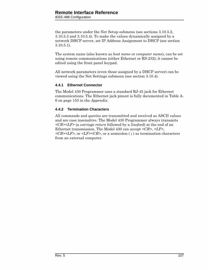
Remote Interface ReferenceIEEE-488 Configuration
the parameters under the Net Setup submenu (see sections 3.10.5.2, 3.10.5.3 and 3.10.5.4). To make the values dynamically assigned by a network DHCP server, set IP Address Assignment to DHCP (see section 3.10.5.1).
The system name (also known as host name or computer name), can be set using remote communications (either Ethernet or RS-232); it cannot be edited using the front panel keypad.
All network parameters (even those assigned by a DHCP server) can be viewed using the Net Settings submenu (see section 3.10.4).
4.4.1 Ethernet Connector
The Model 430 Programmer uses a standard RJ-45 jack for Ethernet communications. The Ethernet jack pinout is fully documented in Table A-6 on page 153 in the Appendix.
4.4.2 Termination Characters
All commands and queries are transmitted and received as ASCII values and are case insensitive. The Model 430 Programmer always transmits <CR><LF> (a carriage return followed by a linefeed) at the end of an Ethernet transmission. The Model 430 can accept <CR>, <LF>, <CR><LF>, or <LF><CR>, or a semicolon ( ; ) as termination characters from an external computer.
Rev. 5 107

Remote Interface ReferenceSystem-Related Commands
4.5 Command Reference
The following paragraphs present all Model 430 Programmer commands and queries in related groups and a detailed description of the function of each command or query is provided. Examples are also provided where appropriate. Return strings may be up to 80 characters in length.
4.5.1 System-Related Commands
• *IDN?
Return the identification string of the Model 430 Programmer. The identification string contains the AMI model number and firmware revision code.
• *RST
Resets the Model 430 Programmer. This is equivalent to cycling the power to the Model 430 Programmer using the power switch. All non-volatile calibration data and battery-backed memory is restored. Status is cleared according to the *PSC setting.
• *TST?
Performs a self-test. Currently always returns “1”.
• <Ctrl-C>
This clears the output buffers of the Model 430 Programmer and prepares the instrument for a new command. Status registers are unaffected. <Ctrl-C> corresponds to ASCII code 03.
• SYSTem:LOCal
Enables all front panel controls. All front panels controls are enabled by default after a power-up or *RST command.
• SYSTem:REMote
Note
The SYSTem:REMote command only disables the front panel controls for purposes of preventing accidental operation of a front panel feature. It is not necessary for this command to be sent prior to using a remote interface. Send the SYSTem:LOCal command, send the *RST command, press SHIFT followed by MENU, or cycle Model 430 Programmer power to re-enable the front panel controls.
Disables all front panel controls. If the Model 430 Programmer is in the remote mode, an asterisk ( * ) will appear in the front panel display in the position just below the ramping character as shown below.
108 Rev. 5
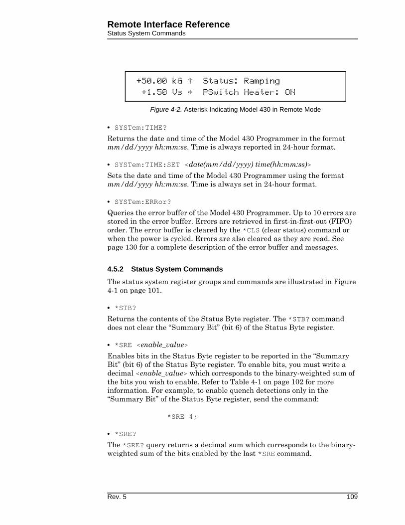
Remote Interface ReferenceStatus System Commands
• SYSTem:TIME?
Returns the date and time of the Model 430 Programmer in the format mm/dd/yyyy hh:mm:ss. Time is always reported in 24-hour format.
• SYSTem:TIME:SET <date(mm/dd/yyyy) time(hh:mm:ss)>
Sets the date and time of the Model 430 Programmer using the format mm/dd/yyyy hh:mm:ss. Time is always set in 24-hour format.
• SYSTem:ERRor?
Queries the error buffer of the Model 430 Programmer. Up to 10 errors are stored in the error buffer. Errors are retrieved in first-in-first-out (FIFO) order. The error buffer is cleared by the *CLS (clear status) command or when the power is cycled. Errors are also cleared as they are read. See page 130 for a complete description of the error buffer and messages.
4.5.2 Status System Commands
The status system register groups and commands are illustrated in Figure 4-1 on page 101.
• *STB?
Returns the contents of the Status Byte register. The *STB? command does not clear the “Summary Bit” (bit 6) of the Status Byte register.
• *SRE <enable_value>
Enables bits in the Status Byte register to be reported in the “Summary Bit” (bit 6) of the Status Byte register. To enable bits, you must write a decimal <enable_value> which corresponds to the binary-weighted sum of the bits you wish to enable. Refer to Table 4-1 on page 102 for more information. For example, to enable quench detections only in the “Summary Bit” of the Status Byte register, send the command:
*SRE 4;
• *SRE?
The *SRE? query returns a decimal sum which corresponds to the binary-weighted sum of the bits enabled by the last *SRE command.
+50.00 kG ¡ Status: Ramping +1.50 Vs * PSwitch Heater: ON
^
Figure 4-2. Asterisk Indicating Model 430 in Remote Mode
Rev. 5 109

Remote Interface ReferenceSETUP Configuration Commands and Queries
• *CLS
Clears the Standard Event register and the error buffer.
• *ESR?
Returns a decimal sum which corresponds to the binary-weighted sum of the contents of the Standard Event register.
• *ESE <enable_value>
Enables bits in the Standard Event register to be reported in the “Standard Event” bit (bit 5) of the Status Byte register. To enable bits, you must write a decimal <enable_value> which corresponds to the binary-weighted sum of the bits you wish to enable. Refer to Table 4-2 on page 104 for more information. For example, to enable all categories of error messages to be reported in bit 5 of the Status Byte register, send:
*ESE 60;
• *ESE?
The *ESE? query returns a decimal sum which corresponds to the binary-weighted sum of the bits enabled by the last *ESE command.
• *PSC {0|1}
Power-On Status Clear. If *PSC 1 is in effect, the Standard Event enable register and the Status Byte enable register are cleared at power on. If *PSC 0 is in effect, the enable registers are not cleared at power on. The default setting is “1”.
• *PSC?
Returns the Power-On Status Clear setting currently in effect. A value of “0” indicates the enable registers are not cleared at power on; a value of “1” indicates the enable registers are cleared at power on.
• *OPC
Sets the “Operation Complete” bit (bit 0) of the Standard Event register when executed. See page 104 for a complete discussion.
• *OPC?
Returns “1” to the requesting interface when executed. See page 105 for more information.
4.5.3 SETUP Configuration Commands and Queries
The SETUP Configuration Commands and Queries provide read/write access to the setup functions available within the Supply (see section 3.10.1), Load (see section 3.10.2), and Misc (see section 3.10.3) submenus.
110 Rev. 5

Remote Interface ReferenceSETUP Configuration Commands and Queries
• SUPPly:TYPE?
Returns the index according to the table below for the selected power supply type according to the table below. This value can be configured only via front panel operation of the SUPPLY setup menu.
• SUPPly:VOLTage:MINimum?
Returns the minimum power supply compliance setting in volts. This value can be configured only via front panel operation using the Supply submenu and is set automatically when a preset supply type is selected.
• SUPPly:VOLTage:MAXimum?
Returns the maximum power supply compliance in volts. This value can be configured only via front panel operation using the Supply submenu and is set automatically when a preset supply type is selected.
Table 4-3. Return Values and Meanings for SUPPly:TYPE? Query
Return Value Meaning
0 AMI 12100PS
1 AMI 12200PS
2 AMI 4Q05100PS
3 AMI 4Q06125PS
4 AMI 4Q06250PS
5 AMI 4Q12125PS
6 AMI 10100PS
7 AMI 10200PS
8 HP 6260B
9 Kepco BOP 20-5M
10 Kepco BOP 20-10M
11 Xantrex XFR 7.5-140
12 Custom
13 AMI Model 05100PS-430-601
14 AMI Model 05200PS-430-601
15 AMI Model 05300PS-430-601
16 AMI Model 05400PS-430-601
17 AMI Model 05500PS-430-601
Rev. 5 111

Remote Interface ReferenceSETUP Configuration Commands and Queries
• SUPPly:CURRent:MINimum?
Returns the minimum output current capacity of the power supply in amperes. This value can be configured only via front panel operation using the Supply submenu and is set automatically when a preset supply type is selected.
• SUPPly:CURRent:MAXimum?
Returns the maximum output current capacity of the power supply in amperes. This value can be configured only via front panel operation using the Supply submenu and is set automatically when a preset supply type is selected.
• SUPPly:MODE?
Returns an integer value corresponding to the voltage output mode according to the table below:
This value can be configured only via front panel operation using the Supply submenu and is set automatically when a preset supply type is selected.
• CONFigure:STABility <percent>
Sets the stability setting in percent.
• STABility?
Returns the stability setting in percent.
• CONFigure:COILconst <value (kG/A, T/A>
Sets the coil constant (also referred to as the field-to-current ratio) per the selected field units. The coil constant must be set to a non-zero, positive value in order to command or query the Model 430 Programmer in units of field.
Table 4-4. Return Values and Meanings for SUPPly:MODE? Query
Return Value Meaning
0 +0.000 to +5.000
1 +0.000 to +10.000
2 -5.000 to +5.000
3 -10.000 to +10.000
4 +0.000 to -5.000
5 +0.000 to +8.000
112 Rev. 5

Remote Interface ReferenceSETUP Configuration Commands and Queries
• COILconst?
Returns the coil constant setting in kG/A or T/A per the selected field units.
• CONFigure:CURRent:LIMit <current (A)>
Sets the Current Limit in amperes. The Current Limit is the largest magnitude operating current allowed during any ramping mode. For four-quadrant power supplies, the Current Limit functions as both a positive and negative current limit.
• CURRent:LIMit?
Returns the Current Limit in amperes.
• CONFigure:CURRent:RATING <current (A)>
Sets the magnet current rating in amperes.
• CURRent:RATING?
Returns the current magnet rating in amperes.
• CONFigure:PSwitch {0|1}
• PSwitch:INSTalled?
“0” indicates that a persistent switch is not installed on the connected superconducting magnet. “1” indicates that a persistent switch is installed. If a persistent switch is installed, the persistent switch heated current and time should be specified. The default value is “1”.
• CONFigure:PSwitch:CURRent <current (mA)>
Sets the persistent switch heater current in mA.
• PSwitch:AUTODetect?
Executes the auto-detection algorithm (Refer to section 3.10.2.7 on page 54) and returns the appropriate persistent switch heater current in mA. Note that after this value is returned, it can be entered into the Model 430 Programmer using the CONFigure:PSwitch:CURRent command.
• PSwitch:CURRent?
Returns the persistent switch heater current setting in mA.
• CONFigure:PSwitch:HeatTIME <time (seconds)>
Sets the time required in seconds for the persistent switch to become resistive after the persistent switch heater has been activated.
• PSwitch:HeatTIME?
Returns the persistent switch heated time in seconds.
Rev. 5 113
Remote Interface ReferenceSETUP Configuration Commands and Queries
• CONFigure:PSwitch:CoolTIME <time (seconds)>
Sets the time required in seconds for the persistent switch to become superconducting after the persistent switch heater has been deactivated.
• CONFigure:PSwitch:PowerSupplyRampRate <rate (A/s)>
Sets the ramp rate that will be used by the power supply to ramp the current1 during the PERSIST. SWITCH CONTROL operation. For more information as to how this PERSIST. SWITCH CONTROL function operates, refer to section 3.6.1 on page 29.
• PSwitch:CoolTIME?
Returns the persistent switch cooled time in seconds.
• PSwitch:PowerSupplyRampRate?
Returns the power supply ramp rate used to change the power supply output when the magnet persistent switch is cool. The units are A/sec.
• CONFigure:PSwitch:CoolingGAIN <percent>
Sets the persistent switch cooling gain in percent.
• PSwitch:CoolingGAIN?
Returns the persistent switch cooling gain in percent.
• CONFigure:QUench:DETect {0|1}
Sending “0” disables the automatic quench detection function of the Model 430 Programmer. “1” enables the automatic quench detection function of the Model 430. See section 3.15 for more information. “0” is the default value.
• QUench:DETect?
Returns “0” indicating automatic quench detection is disabled, or “1” indicating that the automatic quench detection is enabled.
• CONFigure:QUench:RATE <value>
Sets the value of the quench detect rate variable. Allowable values are from “0.1” to “2.0”. “1.5” is the default value (no units).
• QUench:RATE?
Returns the value of the quench detect rate variable (no units).
• CONFigure:ABsorber {0|1}
Sending “0” indicates that an energy absorber is not present in the system. A “1” indicates that an energy absorber is present. “0” is the default value.
1. While the magnet is in persistent mode.
114 Rev. 5

Remote Interface ReferenceSETUP Configuration Commands and Queries
• ABsorber?
Returns “0” indicating that an energy absorber is not present in the system, or “1” indicating that an energy absorber is present.
• CONFigure:RAMP:RATE:UNITS {0|1}
Sets the preferred ramp rate time units. Sending “0” selects seconds. A “1” selects minutes. “0” is the default value. The selected units are applied to both the Model 430 Programmer display and the appropriate remote commands.
• RAMP:RATE:UNITS?
Returns “0” for ramp rates displayed/specified in terms of seconds, or “1” for minutes.
• CONFigure:FIELD:UNITS {0|1}
Sets the preferred field units. Sending “0” selects kilogauss. A “1” selects tesla. “0” is the default value. The selected field units are applied to both the Model 430 Programmer display and the applicable remote commands.
• FIELD:UNITS?
Returns “0” for field values displayed/specified in terms of kilogauss, or “1” for tesla.
• CONFigure:IPNAME <system name>
Sets the system name (also known as host name or computer name), the name by which the Model 430 Programmer is identified on a network.
Note
If the system name value is changed, the Model 430 Programmer power must be cycled off for at least 5 seconds and then back on to complete the change. The new value will be used internally immediately (even before cycling power off and back on), but the IPNAME? query will return the previous system name until the Model 430 Programmer is restarted.
• IPNAME?
Returns the system name (also known as host name or computer name).
4.5.4 Protection Commands and Queries
The Protection Commands and Queries provide read/write access to all protection settings which can be accessed under the Settings Protection submenu. See section 3.10.3.6 for more information regarding the settings protection features of the Model 430 Programmer.
Rev. 5 115

Remote Interface ReferenceSETUP Configuration Commands and Queries
• CONFigure:LOCK:PSwitch:CONTRol {0|1}
Specifies whether use of the PERSIST. SWITCH CONTROL key is locked or unlocked. Sending “0” unlocks. A “1” locks. “0” is the default value.
• LOCK:PSwitch:CONTRol?
Returns “0” for use of the PERSIST. SWITCH CONTROL key unlocked, or “1” for locked.
• CONFigure:LOCK:TARGet {0|1}
Specifies whether use of the TARGET FIELD SETPOINT key is locked or unlocked. Sending “0” unlocks. A “1” locks. “0” is the default value.
• LOCK:TARGet?
Returns “0” for use of the TARGET FIELD SETPOINT key unlocked, or “1” for locked.
• CONFigure:LOCK:RAMP-PAUSE {0|1}
Specifies whether use of the RAMP / PAUSE key is locked or unlocked. Sending “0” unlocks. A “1” locks. “0” is the default value.
• LOCK:RAMP-PAUSE?
Returns “0” for use of the RAMP / PAUSE key unlocked, or “1” for locked.
• CONFigure:LOCK:ZEROfield {0|1}
Specifies whether use of the RAMP TO ZERO key is locked or unlocked. Sending “0” unlocks. A “1” locks. “0” is the default value.
• LOCK:ZEROfield?
Returns “0” for use of the RAMP TO ZERO key unlocked, or “1” for locked.
• CONFigure:LOCK:RAMPrate {0|1}
Specifies whether ramp rate settings are locked or unlocked. Ramp rate settings protected by this setting are: use of the RAMP RATE SHIFT-key menu, editing of the Ramp Segments value (under the Misc submenu) and editing of the Ramp Time Units value (under the Misc submenu). Sending “0” unlocks. A “1” locks. “0” is the default value.
• LOCK:RAMPrate?
Returns “0” for ramp rate settings unlocked, or “1” for locked.
• CONFigure:LOCK:SUPPly {0|1}
Specifies whether the Select Supply picklist value is locked or unlocked. If the Select Supply value is Custom..., then setting Power Supply Lock to Locked also prevents the custom power supply parameters (Min Output Voltage, Max Output Voltage, Min Output Current, Max Output Current
116 Rev. 5

Remote Interface ReferenceSETUP Configuration Commands and Queries
and V-V Mode Input Range) from being edited. Sending “0” unlocks. A “1” locks. “0” is the default value.
• LOCK:SUPPly?
Returns “0” for Select Supply picklist value unlocked, or “1” for locked.
• CONFigure:LOCK:VOLTage:LIMit {0|1}
Specifies whether use of the VOLTAGE LIMIT SHIFT-key menu is locked or unlocked. Sending “0” unlocks. A “1” locks. “0” is the default value.
• LOCK:VOLTage:LIMit?
Returns “0” for use of the VOLTAGE LIMIT SHIFT-key menu unlocked, or “1” for locked.
• CONFigure:LOCK:QUench:RESet {0|1}
Specifies whether use of the RESET QUENCH SHIFT-key command is locked or unlocked. Sending “0” unlocks. A “1” locks. “0” is the default value.
• LOCK:QUench:RESet?
Returns “0” for use of the RESET QUENCH SHIFT-key command unlocked, or “1” for locked.
• CONFigure:LOCK:QUench:RATE {0|1}
Specifies whether use of the quench rate command is locked or unlocked. Sending “0” unlocks. A “1” locks. “0” is the default value.
• LOCK:QUench:RATE?
Returns “0” for use of the quench rate command unlocked, or “1” for locked.
• CONFigure:LOCK:INCR-DECR {0|1}
Specifies whether use of the INCR. FIELD and DECR. FIELD SHIFT-key commands is locked or unlocked. Sending “0” unlocks. A “1” locks. “0” is the default value.
• LOCK:INCR-DECR?
Returns “0” for use of the INCR. FIELD and DECR. FIELD SHIFT-key commands unlocked, or “1” for locked.
• CONFigure:LOCK:FIELD-CURRent {0|1}
Specifies whether use of the FIELD <> CURRENT SHIFT-key command is locked or unlocked. Sending “0” unlocks. A “1” locks. “0” is the default value.
Rev. 5 117

Remote Interface ReferenceSETUP Configuration Commands and Queries
• LOCK:FIELD-CURRent?
Returns “0” for use of the FIELD <> CURRENT SHIFT-key command unlocked, or “1” for locked.
• CONFigure:LOCK:FIELD:UNITS {0|1}
Specifies whether the Field Units value is locked or unlocked (whether accessed through the FIELD UNITS SHIFT-key menu or under the Misc submenu). Sending “0” unlocks. A “1” locks. “0” is the default value.
• LOCK:FIELD:UNITS?
Returns “0” for Field Units value unlocked, or “1” for locked.
• CONFigure:LOCK:STABility {0|1}
Specifies whether the Stability Setting value is locked or unlocked (whether accessed through the STAB. SHIFT-key menu or under the Load submenu). Sending “0” unlocks. A “1” locks. “0” is the default value.
• LOCK:STABility?
Returns “0” for Stability Setting value unlocked, or “1” for locked.
• CONFigure:LOCK:VOLTage:VS-VM {0|1}
Specifies whether use of the Vs <> Vm SHIFT-key command is locked or unlocked. Sending “0” unlocks. A “1” locks. “0” is the default value.
• LOCK:VOLTage:VS-VM?
Returns “0” for use of the Vs <> Vm SHIFT-key command unlocked, or “1” for locked.
• CONFigure:LOCK:VOLTMeter {0|1}
Specifies whether use of the VOLT METER SHIFT-key command is locked or unlocked. Sending “0” unlocks. A “1” locks. “0” is the default value.
• LOCK:VOLTage:VOLTMeter?
Returns “0” for use of the VOLT METER SHIFT-key command unlocked, or “1” for locked.
• CONFigure:LOCK:FINEadjust {0|1}
Specifies whether use of the FINE ADJUST SHIFT-key command is locked or unlocked. Sending “0” unlocks. A “1” locks. “0” is the default value.
• LOCK:VOLTage:FINEadjust?
Returns “0” for use of the FINE ADJUST SHIFT-key command unlocked, or “1” for locked.
118 Rev. 5

Remote Interface ReferenceSETUP Configuration Commands and Queries
• CONFigure:LOCK:COILconst {0|1}
Specifies whether the Coil Constant value (under the Load submenu) is locked or unlocked. Sending “0” unlocks. A “1” locks. “0” is the default value.
• LOCK:VOLTage:COILconst?
Returns “0” for Coil Constant value (under the Load submenu) unlocked, or “1” for locked.
• CONFigure:LOCK:CURRent:LIMit {0|1}
Specifies whether the Current Limit value (under the Load submenu) is locked or unlocked. Sending “0” unlocks. A “1” locks. “0” is the default value.
• LOCK:CURRent:LIMit?
Returns “0” for Current Limit value (under the Load submenu) unlocked, or “1” for locked.
• CONFigure:LOCK:PSwitch:SETtings {0|1}
Specifies whether persistent switch settings are locked or unlocked. Persistent switch settings protected by this setting (all under the Load submenu) are: the PSwitch Installed picklist value, the PSwitch Current value, the PSwitch Heated Time value, PSwitch Current Detect, PSwitch Cooled time, PSw P/S Ramp Rate, and PSwitch Cooling Gain. Sending “0” unlocks. A “1” locks. “0” is the default value.
• LOCK:PSwitch:SETtings?
Returns “0” for persistent switch settings unlocked, or “1” for locked.
• CONFigure:LOCK:QUench:DETect {0|1}
Specifies whether the Enable Quench Detect picklist value (under the Load submenu) is locked or unlocked. Sending “0” unlocks. A “1” locks. “0” is the default value.
• LOCK:QUench:DETect?
Returns “0” for Enable Quench Detect picklist value (under the Load submenu) unlocked, or “1” for locked.
• CONFigure:LOCK:ABsorber {0|1}
Specifies whether the Energy Absorber Present picklist value (under the Load submenu) is locked or unlocked. Sending “0” unlocks. A “1” locks. “0” is the default value.
Rev. 5 119

Remote Interface ReferenceRamp Configuration Commands and Queries
• LOCK:ABsorber?
Returns “0” for Energy Absorber Present picklist value (under the Load submenu) unlocked, or “1” for locked.
• CONFigure:LOCK:BRIGHTness {0|1}
Specifies whether the Display Brightness picklist value (under the Misc submenu) is locked or unlocked. Sending “0” unlocks. A “1” locks. “0” is the default value.
• LOCK:BRIGHTness?
Returns “0” for Display Brightness picklist value (under the Misc submenu) unlocked, or “1” for locked.
• CONFigure:LOCK:NETsetup {0|1}
Specifies whether the Net Setup submenu is locked or unlocked. Sending “0” unlocks. A “1” locks. “0” is the default value.
• LOCK:NETsetup?
Returns “0” for Net Setup submenu unlocked, or “1” for locked.
• CONFigure:LOCK:CURRent:RATING {0|1}
Specifies whether the Magnet Current Rating picklist value (under the LOAD submenu) is locked or unlocked. Sending “0” unlocks. A “1” locks. “0” is the default value.
• LOCK:CURRent:RATING?
Returns “0” for Magnet Current Rating picklist value (under the LOAD submenu) unlocked, or “1” for locked.
• CONFigure:LOCK:RAMPDown {0|1}
Specifies whether the External Rampdown Enabled picklist value (under the LOAD submenu) is locked or unlocked. Sending “0” unlocks. A “1” locks. “0” is the default value.
• LOCK:RAMPDown?
Returns “0” for External Rampdown Enabled picklist value (under the LOAD submenu) unlocked, or “1” for locked.
4.5.5 Ramp Configuration Commands and Queries
The ramp configuration commands set the various parameters required for defining piecewise-linear ramp segments. The external rampdown function also has the ramp segmenting capability. The function operates in a manner similar to the normal ramp as described in section 3.7.1 on page page 33, but parameters can only be edited via the remote interface. See
120 Rev. 5

Remote Interface ReferenceRamp Configuration Commands and Queries
section 3.12 for additional information on determining ramp rates. Also included are queries for collecting the magnet field, current, voltage, and inductance.
• CONFigure:VOLTage:LIMit <voltage (V)>
Sets the ramping Voltage Limit in volts. The ramping Voltage Limit may not exceed the maximum output voltage of the power supply.
• VOLTage:LIMit?
Returns the ramping Voltage Limit in volts.
• CONFigure:CURRent:TARGet <current (A)>
Sets the target current in amperes.
• CURRent:TARGet?
Returns the target current setting in amperes.
• CONFigure:FIELD:TARGet <field (kG, T)>
Sets the target field in units of kilogauss or tesla, per the selected field units. This command requires that a coil constant be defined, otherwise an error is generated.
• FIELD:TARGet?
Returns the target field setting in units of kilogauss or tesla, per the selected field units. This query requires that a coil constant be defined, otherwise an error is generated.
• CONFigure:RAMP:RATE:SEGments <value>
Sets the number of ramp segments (see section 3.7.1 for details of the use of ramp segments).
• RAMP:RATE:SEGments?
Returns the number of ramp segments.
• CONFigure:RAMP:RATE:CURRent <segment>,<rate (A/s, A/min)>,<upper bound (A)>
Sets the ramp rate for the specified segment (values of 1 through the defined number of ramp segments are valid) in units of A/sec or A/min (per the selected ramp rate units), and defines the current upper bound for that segment in amperes (see section 3.7.1 for details of the use of ramp segments).
• RAMP:RATE:CURRent:<segment>?
Returns the ramp rate setting for the specified segment (values of 1 through the defined number of ramp segments are valid) in units of A/sec
Rev. 5 121
Remote Interface ReferenceRamp Configuration Commands and Queries
or A/min (per the selected ramp rate units) and the current upper bound for that range in amperes. The two return values are separated by a comma. For example:
RAMP:RATE:CURRENT:1?0.1000,50.0000
• CONFigure:RAMP:RATE:FIELD <segment>,<rate (kG/s, kG/min, T/s, T/min)>,<upper bound (kG, T)>
Sets the ramp rate for the specified segment (values of 1 through the defined number of ramp segments are valid) in units of kilogauss/second or minute, or tesla/second or minute (per the selected field units and ramp rate units), and defines the field upper bound for that segment in kilogauss or tesla (see section 3.7.1 for details of the use of ramp segments). This command requires that a coil constant be defined; otherwise, an error is generated.
• RAMP:RATE:FIELD:<segment>?
Returns the ramp rate setting for the specified segment (values of 1 through the defined number of ramp segments are valid) in units of kilogauss/second or minute, or tesla/second or minute (per the selected field units and ramp rate units) and the current upper bound for that range in kilogauss or tesla (per the selected field units). This command requires that a coil constant be defined; otherwise, an error is generated. The two return values are separated by a comma. For example:
RAMP:RATE:FIELD:1?0.0100,5.0000
• VOLTage:MAGnet?
Returns the magnet voltage in volts. Requires voltage taps to be installed across the magnet terminals.
• VOLTage:SUPPly?
Returns the power supply voltage commanded by the Model 430 Programmer in volts.
• CURRent:MAGnet?
Returns the current flowing in the magnet in amperes. If the magnet is in persistent mode, the command returns the current that was flowing in the magnet when persistent mode was entered.
• CURRent:SUPPly?
Returns the measured power supply current in amperes.
122 Rev. 5
Remote Interface ReferenceRamp Configuration Commands and Queries
• FIELD:MAGnet?
Returns the calculated field in kilogauss or tesla, per the selected field units. This query requires that a coil constant be defined; otherwise, an error is generated. The field is calculated by multiplying the measured magnet current by the coil constant. If the magnet is in persistent mode, the command returns the field that was present when persistent mode was entered.
• INDuctance?
Returns the measured magnet inductance in henries. Note that the magnet must be ramping when this command is executed. Refer to section 3.10.2.5 on page 53.
• CONFigure:RAMPDown:ENABle {0|1}
Enables the external rampdown function. “1” enables while “0” disables. “0” is the default value.
• RAMPDown:ENABle?
Queries whether the external rampdown function is enabled. Returns “1” for enabled while “0” for disabled. “0” is the default value.
• CONFigure:RAMPDown:RATE:SEGments <# segments>
Sets the number of external rampdown segments.
• RAMPDown:RATE:SEGments?
Returns the number of external rampdown segments.
• CONFigure:RAMPDown:RATE:CURRent <segment>,<rate (A/s, A/min)>, <upper bound (A)>
Sets the external rampdown rate for the specified segment (values of 1 through the defined number of rampdown segments are valid) in units of A/sec or A/min (per the selected rampdown rate units), and defines the current upper bound for that segment in amperes.
• RAMPDown:RATE:CURRent: <segment>?
Returns the external rampdown rate setting for the specified segment (values of 1 through the defined number of rampdown segments are valid) in units of A/sec or A/min (per the selected rampdown rate units) and the current upper bound for that range in amperes. The two return values are separated by a comma. For example:
RAMPDown:RATE:CURRENT:1?0.1000,50.0000
Rev. 5 123

Remote Interface ReferenceRamping State Commands and Queries
• CONFigure:RAMPDown:RATE:FIELD <segment>,<rate (kG/s, kG/min, T/s, T/min)>, <upper bound (Kg, T)>
Sets the external rampdown rate for the specified segment (values of 1 through the defined number of rampdown segments are valid) in units of kilogauss/second or minute, or tesla/second or minute (per the selected field units and rampdown rate units), and defines the field upper bound for that segment in kilogauss or tesla. This command requires that a coil constant be defined; otherwise, an error is generated.
• RAMPDown:RATE:FIELD: <segment>?
Returns the external rampdown rate setting for the specified segment (values of 1 through the defined number of rampdown segments are valid) in units of kilogauss/second or minute, or tesla/second or minute (per the selected field units and rampdown rate units) and the current upper bound for that range in kilogauss or tesla (per the selected field units). This command requires that a coil constant has been defined; otherwise, an error is generated. The two return values are separated by a comma. For example:
RAMPDown:RATE:FIELD:1?0.0100,5.0000
4.5.6 Ramping State Commands and Queries
The ramping state commands control and query the ramping state of the Model 430 Programmer. For more information regarding each state, see section 3.12.
If the ramping state is commanded remotely, the front panel display and LED indicators will update and accurately reflect the commanded ramping state.
• RAMP
Places the Model 430 Programmer in automatic ramping mode. The Model 430 will continue to ramp at the configured ramp rate(s) until the target field/current is achieved.
• PAUSE
Pauses the Model 430 Programmer at the present operating field/current.
• INCR
Places the Model 430 Programmer in the MANUAL UP ramping mode. Ramping continues at the ramp rate until the Current Limit is achieved.
124 Rev. 5

Remote Interface ReferenceSwitch Heater Commands and Queries
• DECR
Places the Model 430 Programmer in the MANUAL DOWN ramping mode. Ramping continues at the ramp rate until the Current Limit is achieved (or zero current is achieved for unipolar power supplies).
• ZERO
Places the Model 430 Programmer in ZEROING CURRENT mode. Ramping automatically initiates and continues at the ramp rate until the power supply output current is less than 0.1% of Imax, at which point the AT ZERO status becomes active.
• STATE?
Returns an integer value corresponding to the ramping state according to the table below:
4.5.7 Switch Heater Command and Query
The PSwitch commands control and query the state of the persistent switch heater. For further information regarding the persistent switch heater, see section 3.13 on page 77.
• PSwitch {0|1}
Turns the persistent switch heater OFF and ON. Sending “0” turns the switch heater OFF. Sending a “1” turns the switch heater ON. The default value is “0”.
Table 4-5. Return Values and Meanings for STATE? Query
Return Value Meaning
1 RAMPING to target field/current
2 HOLDING at the target field/current
3 PAUSED
4 Ramping in MANUAL UP mode
5 Ramping in MANUAL DOWN mode
6 ZEROING CURRENT (in progress)
7 Quench detected
8 At ZERO current
9 Heating persistent switch
10 Cooling persistent switch
Rev. 5 125

Remote Interface ReferenceQuench State Control and Queries
• PSwitch?
Returns a “0” indicating the switch heater is OFF, or a “1” indicating the persistent switch heater is ON.
• PERSistent?
Returns the state of the "MAGNET IN PERSISTENT MODE" LED on the front panel of the Model 430: ‘0” if the LED is OFF; “1” if the LED is ON.
4.5.8 Quench State Commands and Queries
The QUench commands control and query the quench state of the Model 430 Programmer. For further information regarding the quench detection functions, see section 3.15.
• QUench {0|1}
Clears or sets the quenched state. Sending a “0” clears any quench condition (equivalent to using the RESET QUENCH front panel SHIFT-key). Sending a “1” sets a quench condition. Setting the quench state to “1” is equivalent to a quench detection by the Model 430 Programmer — the power supply output is forced to 0 V, the quench output of the rear panel Quench I/O connector is asserted, and all ramping functions are disabled.
• QUench?
Queries the quench state. If a “0” is returned, no quench condition exists. If a “1” is returned, a quench detect has occurred and is still in effect.
• QUench:COUNT?
Queries the number of recorded quench events.
4.5.9 Rampdown State Queries
• RAMPDownFile?
Formats and sends the contents of the standard rampdown file as a formatted ASCII text stream. This allows the user to view the state of both the magnet and Model 430 Programmer during each recorded rampdown event.
• RAMPDownBackup?
Formats and sends the contents of the rampdown backup file as a formatted ASCII text stream. When the number of recorded rampdown events reaches 100, the standard rampdown file becomes the backup file, and a new (empty) standard rampdown file is created. The standard rampdown file contains data from the most recent rampdown events, and the backup file (if it exists) contains data from the 100 rampdown events preceding the oldest record in the standard rampdown file.
126 Rev. 5

Remote Interface ReferenceQuench State Control and Queries
• RAMPDown:COUNT?
Queries the number of recorded rampdown events.
Rev. 5 127

Remote Interface ReferenceTrigger Control and Queries
4.5.10 Trigger Functions
The Model 430 Programmer provides trigger functions which provide a means of collecting operational data with a minimum of commands and directing the output to either or both remote interfaces.
4.5.10.1 Description of the Trigger Functions
The Model 430 Programmer defines a trigger enable register, very similar to the enable registers of the status system, which controls which data is output and the interface to which the data is presented. The trigger enable register is defined as shown in Table 4-6.
To enable the trigger functions, the *ETE <enable_value> command is written with a decimal value corresponding to the binary-weighted sum of the desired functions. Upon receipt of the *TRG command, the Model 430 Programmer places the return data in the appropriate output buffer(s). Data placed in the serial or Ethernet output buffers is transmitted immediately. Note that trigger output data may be placed in both the serial and the Ethernet output buffers if desired.
Table 4-6. Model 430 Programmer Trigger Function Bit Definitions
Bit Number
Bit Name
Decimal Value
Definition
0 Magnet Voltage 1Magnet voltage in volts is included in trigger output.
1 Magnet Current 2Magnet current in amperes is included in the trigger output.
2 Magnet Field 4Magnet field in kilogauss or tesla (per the selected field units) is included in the trigger output.
3 Date and Time 8The trigger date and time is included in the trigger output in the formmm/dd/yyyy hh:mm:ss
4 Not Used 16 Reserved for future use.
5 Formatted Output 32 The trigger output data is formatted.
6 Serial Interface 64Trigger output data is placed in the serial interface output buffer and transmitted immediately.
7 Ethernet Interface 128Trigger output data is placed in the Ethernet output buffer.
128 Rev. 5

Remote Interface ReferenceTrigger Functions
Note
Since trigger data is output immediately to the serial interface, it is possible to use the trigger functions to drive a terminal, modem, or a line printer (if a serial-to-parallel or serial-to-USB converter is available) connected to the serial interface.
If the trigger output data is not formatted, the data will be comma delimited and returned in the order of time, magnet field, magnet current, and magnet voltage. Only the data enabled for output will appear in the trigger output string.
4.5.10.2 Trigger Commands and Queries
• *ETE <enable_value>
Enables trigger functions according to the definitions in Table 4-6. To enable the trigger functions, you must write a decimal <enable_value> which corresponds to the binary-weighted sum of the functions you wish to enable. For example, to enable formatted output of the time, magnet field, and the magnet voltage to the serial interface, send the command:
*ETE 109;
The return data in the serial output buffer would appear as (with the field units selected as tesla):
10/23/2007 13:03:14, FIELD= 20.002 T, VOLTAGE= 2.05 V
• *ETE?
The *ETE? query returns a decimal sum which corresponds to the binary-weighted sum of the trigger functions enabled by the last *ETE command.
• *TRG
Initiates trigger output to the enabled interfaces for trigger functions.
Rev. 5 129

Remote Interface ReferenceError Messages
4.6 Error Messages
If an error occurs, the Model 430 Programmer will beep, load the internal error buffer with the error code and description, and set the appropriate bits in the standard event and status byte registers if enabled by the user. Error codes are returned with a negative 3 digit integer, then a comma, and then a description enclosed in double quotes.
Use the SYSTem:ERRor? query to retrieve the errors in first-in-first-out (FIFO) order. Errors are removed from the internal error buffer as they are read. The Model 430 Programmer can store up to 10 errors.
If more than 10 errors have occurred, the last error stored in the internal error buffer is replaced with -304,”Error buffer overflow”. No additional errors are stored until you have cleared at least one error from the buffer. If no errors have occurred and the SYSTem:ERRor? query is sent to the Model 430 Programmer, the instrument will return:
0,”No errors”
Error strings may contain up to 80 characters. Errors are classified in the following categories: command errors, query errors, execution errors, and device errors. Each category corresponds to the identically named bit in the standard event register (see section 4.2.3). If an error occurs in any one of the categories, the corresponding bit in the standard event register is set and remains set until cleared by the user.
4.6.1 Command Errors
• -101,”Unrecognized command”
The command string sent was not identified as valid. Check the command string for invalid characters or separators, syntax errors, or for errors in the mnemonics. Spaces are not allowed before or after colon separators, and at least one space must separate a command string from the parameter(s).
• -102,”Invalid argument”
The argument provided as a parameter for the command was invalid. Value arguments must be of the following form:
• an optional plus or minus sign,
• a sequence of decimal digits, possibly containing a single decimal point, and
• an optional exponent part, consisting of the letter e or E, an optional sign, and a sequence of decimal digits.
Enable_value arguments must be within the inclusive range of 0 to 255.
130 Rev. 5
Remote Interface ReferenceError Messages
• -103,”Non-boolean argument”
The command required a parameter in the form of 0 or 1. No other form of the parameter is allowed.
• -104,”Missing parameter”
The command required at least one argument which was not found before the termination character(s).
• -105,”Out of range”
At least one of the parameter values received was out of the valid range. Refer to the summary of valid ranges for the Model 430 Programmer settings on page 90. Be sure to note the field units and ramp units settings and check any unit conversions.
• -106,”Undefined coil const”
The user attempted to invoke a command with units of field without first setting a value for the coil constant. The coil constant must be a non-zero, positive value.
• -107,”No switch installed”
The user attempted to activate the persistent switch heater when no switch is installed. Before activating the persistent switch heater, the user must indicate a switch is installed and set the switch current and heating time (see page 54).
• -108,“Not Ramping”
The command that was issued requires the Model 430 Programmer to be ramping for the duration of command processing, and the Model 430 Programmer was either not ramping when the command was issued, or stopped ramping before the command processing was completed.
4.6.2 Query Errors
• -201,”Unrecognized query”
The query string sent (identified as a query by a ?) was not identified as valid. Check the query string for invalid characters or separators, syntax errors, or for errors in the mnemonics. Spaces are not allowed before or after colon separators.
• -202,”Undefined coil const”
The user attempted to invoke a query with units of field without first setting a value for the coil constant. The coil constant must be a non-zero, positive value.
Rev. 5 131

Remote Interface ReferenceError Messages
• -203,”Query interrupted”
A new query was processed before the return string of a previous query had been completely transmitted to the host. The new query clears the remaining data and replaces it with the new return string.
4.6.3 Execution Errors
• -301,”Heating switch”
The user attempted to initiate a ramping function during the persistent switch heating period. Ramping functions are disallowed during the heating period.
• -302,”Quench condition”
The user attempted to change the ramping state while a quench condition was active. A quench condition must be cleared via the RESET QUENCH SHIFT-key or by remote command before the ramping state can be modified.
• -303,”Input overflow”
The four input buffers are all occupied with unprocessed commands or queries. The command or query is lost. Review the handshaking section on page 104 for directions for avoiding input overflow errors.
• -304,”Error buffer overflow”
More than 10 errors have occurred. For further errors to be recorded in the internal buffer, at least one error must be cleared.
4.6.4 Device Errors
• -401,”Checksum failed”
The non-volatile memory which stores the calibration data for the Model 430 Programmer is corrupted. Contact an Authorized AMI Technical Representative for further instructions. Do not continue to use the Model 430 Programmer to operate a superconducting magnet.
• -402,”Serial framing error”
The baud rate of the Model 430 Programmer and host device are not identical. The host device must be set to the same baud rate as the Model 430 Programmer (115200).
• -403,”Serial parity error”
The number of data bits and/or the parity of the Model 430 Programmer and the host device are not identical. The host device must be set for the
132 Rev. 5

Remote Interface ReferenceError Messages
same number of data bits, stop bits and parity as the Model 430 Programmer (8 data bits, 1 stop bit and no parity).
• -404,”Serial data overrun”
The received buffer of the Model 430 Programmer was overrun. Verify that the host device has hardware handshaking (RTS/CTS) enabled.
Rev. 5 133

Remote Interface ReferenceError Messages
134 Rev. 5

5 Service
5.1 System Component Maintenance
Caution
These electronic devices are sensitive to electrostatic-discharge (ESD) damage when opened (cover removed). Observe all standard ESD precautions when handling opened power supplies and instruments. Refer to section 5.2.1 on page 135.
5.1.1 Model 430 Programmer Routine Maintenance
The Model 430 Programmer was designed and manufactured to give years of reliable service. The only routine maintenance required is to keep the exterior surfaces of the Model 430 Programmer clean by gently wiping with a damp cloth moistened with a mild detergent.
5.1.2 Model 4Q06125PS Power Supply Routine Maintenance
The Model 4Q06125PS is specifically designed to minimize the need for periodic maintenance, and AMI does not recommend a periodic calibration or service. Keep the exterior surfaces clean by gently wiping with a damp cloth moistened with a mild detergent. The inside of the Model 4Q06125PS unit should be periodically cleaned of dust and grime to ensure continued cooling efficiency. The maintenance interval is dependent on the application and environment; in normal laboratory environments the recommended maintenance interval is six (6) months.
5.2 Troubleshooting Hints
The following paragraphs serve as an aid to assist the user in troubleshooting a potential problem with a superconducting magnet system. If the user is not comfortable in troubleshooting the system, contact an AMI Technical Support Representative for assistance. Refer to “Additional Technical Support” on page 143.
5.2.1 Electrostatic Discharge Precautions
The system contains components which are susceptible to damage by Electrostatic Discharge (ESD). Take the following precautions whenever the cover of electronic equipment is removed.
1. Disassemble only in a static-free work area.
Rev. 5 135
ServiceTroubleshooting Hints
2. Use a conductive workstation or work area to dissipate static charge.
3. Use a high resistance grounding wrist strap to reduce static charge accumulation.
4. Ensure all plastic, paper, vinyl, Styrofoam® and other static generating materials are kept away from the work area.
5. Minimize the handling of the system and all static sensitive components.
6. Keep replacement parts in static-free packaging.
7. Do not slide static-sensitive devices over any surface.
8. Use only antistatic type desoldering tools.
9. Use only grounded-tip soldering irons.
10. Use only static-dissipative hand tools (pliers, cutters, etc.).
5.2.2 The Model 430 does not appear to be energized
1. Ensure that the Model 430 Programmer is energized from a power source of proper voltage.
Warning
If the Model 430 Programmer is found to have been connected to an incorrect power source, return the instrument to AMI for evaluation to determine the extent of the damage. Frequently, damage of this kind is not visible and must be determined using test equipment.
2. Verify continuity of all line fuses (F1, F2, F3, F4, F5, F6 and F7) located on the Model 430 Programmer printed circuit board.
Warning
This procedure is to be performed only when the Model 430 Programmer is completely de-energized by removing the power-cord from the power receptacle. Failure to do so could result in personnel coming in contact with high voltages capable of producing life-threatening electrical shock.
a. Ensure the Model 430 Programmer and all connected components are de-energized by first shutting down the system and then disconnecting the power cord from the power source.
136 Rev. 5

ServiceTroubleshooting Hints
b. Remove the Model 430 Programmer top cover and check all fuses for continuity.
c. If a fuse is bad, replace with a fuse of identical rating:
Caution
Installing fuses of incorrect values and ratings could result in damage to the Model 430 Programmer in the event of component failure.
c. Replace the fuse and securely fasten the Model 430 Programmer top cover. Reconnect the power-cord.
4. Verify the input voltage selector switch on the Model 430 Programmer printed circuit board is in the proper position for the available input power. Checking the input voltage selector requires removal of the top cover of the Model 430 Programmer. Observe the same safety procedures as presented in step 2, above.
5.2.3 FAILURE TO LOAD message displayed after power-up
1. Power the Model 430 Programmer off using the front panel power switch.
2. Wait at least 15 seconds.
3. Power the Model 430 Programmer on using the front panel switch.
Table 5-1. V-V Mode Input Range Picklist Values
Fuse Identification Fuse Rating Fuse Size
F1 T 800 mA
5 x 20 mm
F2T 250 mA
F3
F4
T 100 mAF5
F6
F7
Rev. 5 137
ServiceTroubleshooting Hints
5.2.4 Power supply unstable - magnet voltage oscillates
Note
If the size of the voltage oscillation is small (approximately 0.1 volt or smaller), see step 1, below. If the voltage oscillation is larger than approximately 0.1 volt, see steps 1 through 4, below.
1. Adjust the persistent switch heater current to a value 10 mA larger than the present value. If the oscillation stops, adjust the heater current to as small a value as possible that maintains magnet voltage stability.
2. Verify the power supply controlled by the Model 430 Programmer is configured for remote programming, voltage-to-voltage mode. Consult the manufacturer’s operations manual for the necessary power supply configuration.
3. Verify that the persistent switch heater is operating. Also, verify that the actual persistent switch in the magnet is correctly installed and connected.
Note
If the persistent switch heater is activated without an inductive load present at the supply outputs, oscillating current will result. The Model 430 Programmer is designed to operate large inductive loads with only relatively small resistive characteristics (i.e. superconducting magnets). The Model 430 Programmer is not designed for use as a general purpose power supply controller for resistive loads.
4. If the magnet has no persistent switch installed, or has a small inductance (typically less than 3 H), then adjust the stability setting for the Model 430 Programmer. As this setting is increased, the system should become more stable. For best results, minimize the amount that this value is adjusted from 0.0%. Refer to section 3.10.2.1.
5.2.5 The power supply system will not charge the magnet.
1. Verify system interconnecting wiring. Refer to section 2.5. If the Model 430 Programmer shows “+0.00 A ↑ Status: Ramping” with the supply voltage, Vs, increasing or at the programmed Voltage Limit (as indicated by the reverse video “V” status indicator), there may be a problem with the power supply. Verify the power supply is on and the program out connection from the Model 430 Programmer to the program voltage input to the power supply is intact.
138 Rev. 5

ServiceTroubleshooting Hints
2. Verify the power supply is configured for remote programming, voltage-to-voltage mode.
5.2.6 Cannot charge the magnet at the selected ramp rate.
1. Ensure the Model 430 Programmer is properly configured for the connected power supply. See section 3.10.1.
2. Ensure that the persistent switch heater is on and the switch heated time has expired. Ramping is disabled during the switch heating period.
3. Check the value of the Voltage Limit. Refer to section 3.7.2.
4. Check for excessive wiring resistances in the magnet-power supply loop which may prevent proper charge/discharge voltages at the magnet. Use the local voltmeter on the power supply to see if the proper voltages exist across the various components in the magnet power loop. Loose or oxidized interconnections often exhibit excessive resistances.
5.2.7 Cannot discharge the magnet at the selected ramp rate
1. Ensure that the persistent switch heater is on and the switch heated time has expired. Ramping is disabled during the switch heating period.
2. Check the value of the Voltage Limit. Refer to section 3.7.2.
5.2.8 Cannot charge the magnet to desired field.
3. Ensure that the Model 430 Programmer supply setup submenu is configured to match the connected power supply, e.g. check that the Model 430 Programmer is configured for the proper voltage-to-voltage programming range according to section 3.10.1.1.1.5.
5.2.9 Current in only one direction from 4-quadrant supply
1. Ensure the Model 430 Programmer is configured to allow negative power supply voltage according to section 3.10.1.1.1.1 and negative power supply currents according to section 3.10.1.1.1.3.
2. Verify that the Model 430 Programmer is configured for the proper voltage-to-voltage programming range according to section 3.10.1.1.1.5.
5.2.10 Cannot place the magnet in persistent mode.
Ensure there is adequate LHe level in the cryostat to allow the persistent switch to cool to the superconducting state.
Rev. 5 139

ServiceTroubleshooting Hints
5.2.11 Cannot bring the magnet out of persistent mode.
1. If a PSwitch Error was indicated when the PERSIST. SWITCH CONTROL key was used to turn on the persistent switch heater current, then there is a problem with the wiring to the persistent switch heater. Check the continuity between the persistent switch heater power supply output pins at the rear panel MAGNET STATION CONNECTORS and the connectors on the magnet support stand top plate. Refer to Table A-1 on page 145.
2. Verify that the output of the persistent switch heater is set to the appropriate value. Refer to section 3.10.2.8 and Figure 3-13 on page 73.
3. Ensure that there is sufficient time for the switch to warm before the power supply current is changed. Increase the persistent switch heating time if needed. Refer to section 3.10.2.9.
5.2.12 The magnet quenches for no apparent reason
1. Ensure the magnet is not being charged at a ramp rate exceeding the capabilities of the magnet. Exceeding the designed rate for ramping the magnet may cause a quench or it may turn on protective diodes on the magnet which may appear very similar to a quench.
2. Ensure there is adequate LHe level in the cryostat. For systems operating at less then 4.2K, ensure the magnet is cooled to the temperature specified by the magnet manufacturer.
3. For conduction-cooled magnets, ensure the magnet temperature is proper and in accordance with the magnet manufacturer’s specifications.
4. Disable the Model 430 Programmer quench detection feature (see section 3.15.2 on page 88) if you suspect the Model 430 Programmer is falsely indicating a quench condition.
5.2.13 Cannot lower the magnet field
1. Ensure the magnet is not in the persistent mode. Refer to section 3.13.3 for the procedure to remove a magnet from the persistent mode of operation.
2. If a PSwitch Error was indicated when the PERSIST. SWITCH CONTROL key was used to turn on the persistent switch heater current, then there is a problem with the wiring to the persistent switch heater. Check the continuity between the persistent switch heater power supply output pins at the rear panel MAGNET
140 Rev. 5

ServiceTroubleshooting Hints
STATION CONNECTORS and the connectors on the magnet support stand top plate. Refer to Table A-1 on page 145.
5.2.14 There is excessive LHe boil-off during operation.
Excessive LHe consumption is usually attributable to one or both of the following: thermal energy being conducted into the cryostat or electrical energy being converted into thermal energy within the cryostat. Analyzing the circumstances under which the high boil-off occurs will help determine what is causing the problem.
1. For magnets equipped with switches for persistent operation, verify that the persistent switch heater power supply is operating at the proper current for the installed switch. Excessive currents cause excessive boiloffs. The typical switch requires approximately 45 mA to function correctly. Refer to the documentation provided with the magnet for proper operating current. See Figure 3-13 on page 73.
2. Verify that the protective diodes on the magnet are not turning on. Damaged diodes may short causing current to flow through them whenever magnet current flows and cause excessive heating. This can be identified by observing a change in the apparent field-to-current ratio since some of the current is bypassing the coil. If the boil off rate returns to normal with the magnet de-energized, this may indicate a defective diode.
3. Ensure that there are no inadvertent thermal paths between the cryogenic environment and the 300K environment. Ensure all transfer lines are removed from the cryostat; check the position of break-away vapor-cooled current leads.
4. Ensure the LHe level sensor is not continuously energized if continuous level indication is not necessary.
5. Ensure the vacuum in vacuum-jacketed dewars is of sufficiently low pressure.
5.2.15 Cannot display the magnetic field strength, only current
Enter a coil constant in accordance with section 3.10.2.2 on page 50.
Note
Setup menu limits are always required in terms of current.
Rev. 5 141
ServiceTroubleshooting Hints
5.2.16 Cannot use remote communications commands.
1. Verify your communications cable integrity and wiring. Refer to Table A-6 on page 153 and Table A-7 on page 153 for wiring of remote communications connectors.
2. Check to make sure you are sending the correct termination to the Model 430 Programmer. If you are using RS-232, make sure the baud rate, number of stop bits, and data bits/parity settings of the host device are matched to those of the Model 430 Programmer (see section 4.3). If you are using Ethernet communications, check all Model 430 Programmer network settings (see sections 3.10.4 and 3.10.5).
3. Check your host communications software and make sure it is recognizing the return termination characters from the Model 430 Programmer. The return termination characters are <CR><LF>.
4. If the Model 430 Programmer is responding repeatedly with errors, try a device clear command (DCL) or powering the Model 430 Programmer off and then back on. Be sure you are sending valid commands.
5.2.17 Magnet current drifts unacceptably while PSwitch cooling
1. Set the PSwitch Cooling Gain to 25% and cool the switch. Observe the current on the front of the Model 430 Programmer while the persistent switch is cooling
2. If the switch will not lock (cool to superconducting), resulting in a PSW lock error, reduce the PSwitch Cooling Gain by several percent and attempt cooling the switch again.
3. If the switch cools but the magnet current has excessive drift during cooling, increase the PSWitch Cooling Gain value by several percent.
5.2.18 Model 430 appears to lock up when connecting to network
Note
If the IP Address Assignment value is changed, the Model 430 Programmer power must be cycled off for at least 15 seconds and then back on to complete the change.
On power-up, when connecting via Ethernet (Internet Protocol), the Model 430 will display the firmware version screen until an IP address has been obtained. On busy or slow networks, IP address assignment may take several seconds (even as much as a minute or
142 Rev. 5
ServiceReturn Authorization
so on very slow networks). The additional time required may give the temporary false appearance of Model 430 "lockup".
5.3 Additional Technical Support
If the cause of the problem cannot be located, contact an AMI Technical Support Representative at (865) 482-1056 for assistance. The AMI technical support group may also be reached by internet e-mail at [email protected]. Additional technical information, latest software releases, etc. are available at the AMI web site at:
http://www.americanmagnetics.com
Do not return the Model 430 Programmer or other magnet system components to AMI without prior return authorization.
5.4 Return Authorization
Items to be returned to AMI for repair (warranty or otherwise) require a return authorization number to ensure your order will receive proper attention. Please call an AMI representative at (865) 482-1056 for a return authorization number before shipping any item back to the factory.
Rev. 5 143

ServiceReturn Authorization
144 Rev. 5

Appendix
A.1 Magnet Station Connectors
The two 25-pin D-sub female Magnet Station Connectors are identically wired and connected pin-for-pin internally. Spare connections may be used for custom coil taps or other signals.
Table A-1. Magnet Station Connectors Pin Definitions
Pin Function Pin Function
1 LHe Sensor I+ (Red) 14 spare
2 LHe Sensor I− (Black) 15 spare
3 LHe Sensor V− (Yellow) 16 spare
4 LHe Sensor V+ (Blue) 17 spare
5 Temperature Sensor I+ (Red) 18 spare
6 Temperature Sensor I− (Black) 19 spare
7 Temperature Sensor V− (Yellow) 20 spare
8 Temperature Sensor V+ (Blue) 21 spare
9 Persistent Switch Heater I+ (Red) 22 spare
10 Persistent Switch Heater I− (Black) 23 spare
11 Magnet Voltage Tap V+ (Yellow) 24 spare
12 Magnet Voltage Tap V− (Blue) 25 spare
13 spare
Rev. 5 145
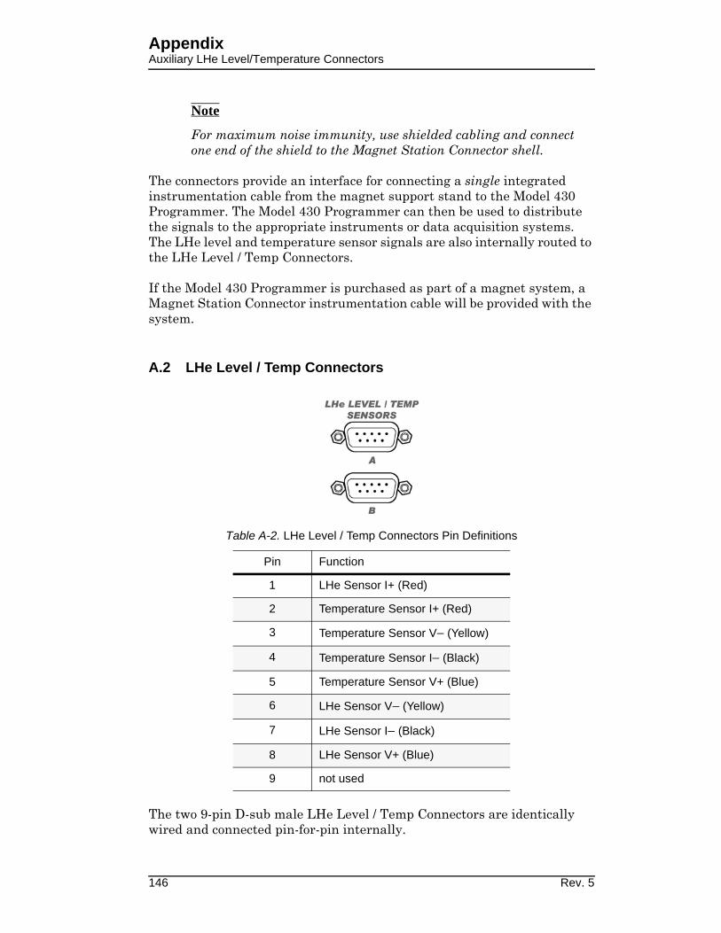
AppendixAuxiliary LHe Level/Temperature Connectors
146 Rev. 5
Note
For maximum noise immunity, use shielded cabling and connect one end of the shield to the Magnet Station Connector shell.
The connectors provide an interface for connecting a single integrated instrumentation cable from the magnet support stand to the Model 430 Programmer. The Model 430 Programmer can then be used to distribute the signals to the appropriate instruments or data acquisition systems. The LHe level and temperature sensor signals are also internally routed to the LHe Level / Temp Connectors.
If the Model 430 Programmer is purchased as part of a magnet system, a Magnet Station Connector instrumentation cable will be provided with the system.
A.2 LHe Level / Temp Connectors
The two 9-pin D-sub male LHe Level / Temp Connectors are identically wired and connected pin-for-pin internally.
Table A-2. LHe Level / Temp Connectors Pin Definitions
Pin Function
1 LHe Sensor I+ (Red)
2 Temperature Sensor I+ (Red)
3 Temperature Sensor V− (Yellow)
4 Temperature Sensor I− (Black)
5 Temperature Sensor V+ (Blue)
6 LHe Sensor V− (Yellow)
7 LHe Sensor I− (Black)
8 LHe Sensor V+ (Blue)
9 not used

AppendixShunt Terminals
The connectors route the incoming signals from the Magnet Station Connectors to external level and/or temperature instruments. If an AMI Liquid Helium Level Instrument is purchased with the Model 430 Programmer and magnet system, an LHe level cable will be provided.
Warning
Although the LHe level sensor connector terminals are isolated from earth ground and therefore touching one terminal is not hazardous, the voltage between terminals is at a hazardous potential if an AMI Liquid Helium Level Instrument is connected and energized. The LHe level sensor pins are designed for use with an AMI LHe sensor and the wiring for the sensor is to have no live parts which are accessible. Conductors connected to its terminals must be insulated from user contact by basic insulation rated for 150 VAC (Category I).
Note
For maximum noise immunity, use shielded cabling and connect one end of the shield to the LHe Level / Temp Connector shell.
A.3 Programmer Shunt Terminals
The shunt terminals should be connected so that positive conventional current flows from the + terminal to the − terminal. Refer to section 2 on page 11 for a detailed description of the system interconnections.
Warning
Exercise caution near the shunt terminals when operating a magnet. Metallic objects shorted across the shunt terminals may conduct large DC currents which are capable of melting the object and causing severe burns.
Caution
Do not overtighten the nuts on the shunt terminals of the Model 430 Programmer (refer to specifications in table on page 8). Overtightening can result in damage to the terminals.
Rev. 5 147

AppendixProgram Out Connector
A.4 Program Out Connector
The Program Out 15-pin D-sub male connector provides up to a −10 Vdc to +10 Vdc output designed to drive the remote voltage-to-voltage programming input of a connected power supply. Refer to “Installation” on page 11 for a detailed description of the system interconnections. Pin 11 of the Program Out connector is the program out voltage. Pin 4 of the Program Out connector is the output return. All other pins of the Program Out connector are unused.
Note
For maximum noise immunity, the Model 430 Programmer chassis and the chassis of any connected power supply should be tightly
Table A-3. Program Out Connector Pin Definitions
Pin Function
1 not used
2 not used
3 not used
4 Program Out Common
5 not used
6 not used
7 not used
8 not used
9 not used
10 not used
11 Program Out Voltage
12 not used
13 not used
14 not used
15 not used
148 Rev. 5

AppendixQuench I/O Connector
electrically coupled. This can be accomplished through the rack mounting or by using a grounding strap between the chassis.
A.5 Quench I/O Connector
The Quench I/O connector provides pins for external quench detection input, quench detection output, and external rampdown input. The shell lugs of the connector are connected to the Model 430 Programmer chassis ground. The Quench I/O connector is a 9-pin D-sub female connector.
A.5.1 External Quench Detection Input
The external quench detection input allows the user to facilitate his own quench detection circuitry, the output of which is wired to the Model 430 Programmer. The external input overrides the internal quench detection function of the Model 430 Programmer and cannot be disabled.
Caution
The external quench detection input is a dry contact input, not galvanically isolated from the Model 430 Programmer internal circuitry. To avoid noise problems and potential damage to the Model 430 Programmer, it is very important that the dry contacts to
Table A-4. Quench I/O Connector Pin Definitions
Pin Polarity Function
1n/a
Quench Output(Model 430 Programmer NO dry contact)2
3 not used
4 circuit common Quench Input(customer-suppled external NO dry contact)5 +
6 circuit common Rampdown Input(customer-supplied external NO dry contact)7 +
8not used
9
Rev. 5 149

AppendixQuench I/O Connector
which the input is connected be galvanically isolated from any external circuitry.
It is recommended that the external quench detection input be driven by the contacts of a low level dry contact relay, which will galvanically isolate the input from all other circuitry.
When the external quench detection input pins (pins 4 and 5 of the Quench I/O connector) are shorted together, it is the same as if an Model 430 Programmer internal quench detection occurred. Refer to section 3.15 on page 86 for details.
A.5.2 External Rampdown Input
When enabled1, the external rampdown input initiates a rampdown of the magnetic field of the magnet when triggered.
Caution
The external rampdown input is a dry contact input, not galvanically isolated from the Model 430 Programmer internal circuitry. To avoid noise problems and potential damage to the Model 430 Programmer, it is very important that the dry contacts to which the input is connected be galvanically isolated from any external circuitry.
It is recommended that the external rampdown input be driven by the contacts of a low level dry contact relay, which will galvanically isolate the input from all other circuitry.
When the external rampdown input pins (pins 6 and 7 of the Quench I/O connector) are shorted together for more than 10 milliseconds, the Model 430 Programmer enters external rampdown mode. If the magnet is in driven mode, the Model 430 Programmer ramps the magnet field/current to zero. If the magnet is in persistent mode, the Model 430 Programmer ramps the power supply to match the persistent magnet current, turns on the persistent switch heater, waits the specified heated time and then ramps the magnet field/current to zero.
This function may be used with an AMI Model 134 or 135 Liquid Helium Level Instrument. The Level instrument has a NO relay associated with the low level condition and this contact closure can be connected to the External Rampdown Input so that when a low helium level occurs in a system, the magnet is safely and automatically ramped down, preventing a magnet quench. AMI offers a cable for this purpose or the user can make
1. Refer to “Enable External Rampdown” on page 58.
150 Rev. 5

AppendixQuench I/O Connector
a suitable cable to connect pins 5 and 6 on J2 of the 13x instrument to pins 6 and 7 of the 430 Programmer, Quench I/O connector.
Caution
The separate external segmented-rampdown option described below ignores the Voltage Limit during the rampdown process.
Note
If the number of external-rampdown ramp segments is set to zero, the modified rampdown is not used and the standard ramp rate table will be effective during external rampdown. The Model 430 Programmer defaults to an empty rampdown table (number of segments equal zero).
A separate segmented-ramp-rate table is available for external rampdown. This option is accessible only via the external interface commands. See section 4.5.5 on page 120.
A.5.3 External Quench Detection Output
The external quench detection output is a set of dry contacts (pins 1 and 2 of the Quench I/O connector) which close when the Model 430 Programmer internal circuitry detects a quench condition. Note that the Model 430 Programmer internal quench detection must be enabled to assure that the Model 430 Programmer will indicate a detected quench (see section 3.10.2.13 on page 57).
The contacts remain shorted (when a quench has been detected) until the RESET QUENCH SHIFT-key is used to clear the quench condition.
Rev. 5 151

AppendixQuench I/O Connector
A.6 Aux Inputs Connector
The Aux Inputs connector provides pins for external voltage inputs, reserved for future use. The shell lugs of the connector are connected to the Model 430 Programmer chassis ground. The Aux Inputs connector is a high density 15-pin D-sub female connector.
Each input pin has a 1 megohm resistor to analog circuit common. The inputs are differential inputs. Aux Input 1 and Aux Input 2 have a ± 1 V nominal input voltage range. Aux Input 3, Aux Input 4, Aux Input 5 and Aux Input 6 have a ± 10 V nominal input voltage range.
Table A-5. Aux Inputs Connector Pin Definitions
Pin Function
1 Aux Input 1 +
2 Aux Input 1 —
3 Aux Input 2 +
4 Aux Input 2 —
5 not used
6 Aux Input 3 +
7 Aux Input 3 —
8 Aux Input 4 +
9 Aux Input 4 —
10 not used
11 Aux Input 5 +
12 Aux Input 5 —
13 Aux Input 6 +
14 Aux Input 6 —
15 not used
152 Rev. 5

AppendixRS-232/422 Connector
A.7 Ethernet Connector
A.8 RS-232 Connector
The RS-232 connector is a standard DTE 9-pin D-sub male connector
Table A-6. Ethernet RJ-45 Connector Pin Definitions
Pin Mnemonic Function
1 TXD+ Transmit differential output +
2 TXD— Transmit differential output —
3 RXD+ Transmit differential input +
4not used
5
6 RXD— Transmit differential input —
7not used
8
Table A-7. RS-232 Connector Pin Definitions
Pin Mnemonic Function
1 DCD Data Carrier Detect
2 RXD Receive Data
3 TXD Transmit Data
4 DTR Data Terminal Ready
5 GND Signal Ground
6 DSR Data Set Ready
7 RTS Request To Send
Rev. 5 153

AppendixAbbreviations and Acronyms
A.9 Abbreviations and Acronyms used in this Manual
8 CTS Clear to Send
9 RI Ring Indicator
Table A-8. PC (DB9)-to-Model 430 RS-232 Cable Connections
PC (DTE)DB9 Pin
Model 430 (DTE) DB9 Pin
1, 6 4
2 3
3 2
4 6, 1
5 5
7 8
8 7
Table A-9. Abbreviations and Acronyms
Term Meaning
AC; acAlternating Current; strictly, electrical current that periodically reverses direction. Typically used also to describe an electrical power source in terms of the voltage. For example, 240 Vac.
ASCII
American Standard Code for Information Interchange; numerical representation of characters such as 'a' or '@' or an action (such as line-feed); 'plain' raw text with no formatting such as tabs, bold or underscoring
CR Text Carriage-Return character
CT Current Transducer
CTS DTE clear-to-send signal
DB9Type of electrical connector containing 9 pins arranged in two parallel rows of 4 pins and 5 pins each)
DB15Type of electrical connector containing 15 pins arranged in two parallel rows of 7 pins and 8 pins each
Table A-7. RS-232 Connector Pin Definitions (Continued)
Pin Mnemonic Function
154 Rev. 5

AppendixAbbreviations and Acronyms
D-SubTerm referring to the family of connectors containing an odd number of pins in two parallel rows with a 1-pin difference in pins-per-row (DB9, DB15, and DB25 are most common)
DC; dcDirect Current; strictly, electrical current that flows in only one direction. Typically used also to describe an electrical power source in terms of the voltage. For example, 12 Vdc.
DCEData Communication Equipment: The devices of a communications network, such as modems, that connect the communication circuit between the data source and destination (DTE’s).
DHCPDynamic Host Configuration Protocol; a computer networking protocol
which dynamically distributes the IP address to networked devices
di/dt Current flow rate of change
DSPDigital Signal Processing; digital representation and processing of signals typically converted to/from analog signals external to the processor.
DTEData Terminal Equipment: the source or destination of data in a communication connection. DTE’s are connected to DCE which in turn is connected to the communication channel.
EFT Electrical Fast Transient
EMC Electromagnetic Compatibility
Eo Power supply output voltage
ESD Electrostatic Discharge
FIFO First-in / First-out
FTP File Transfer Protocol
i, I Electrical current flow
Io Power supply output current
IEC International Electrotechnical Commission
IEEE Institute of Electrical and Electronics Engineers
I/O
Input/Output; The hardware and associated protocol that implement communication between information processing systems and/or devices. Inputs are the signals or data received by the system or device, and outputs are the signals or data sent from it.
IPInternet Protocol; when used with “address”, refers to a numerical internet address
Table A-9. Abbreviations and Acronyms (Continued)
Term Meaning
Rev. 5 155
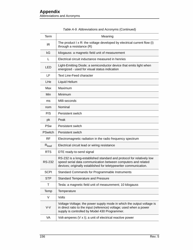
AppendixAbbreviations and Acronyms
IRThe product I x R: the voltage developed by electrical current flow (I) through a resistance (R)
kG kilogauss: a magnetic field unit of measurement
L Electrical circuit inductance measured in henries
LEDLight-Emitting Diode; a semiconductor device that emits light when energized - used for visual status indication
LF Text Line-Feed character
LHe Liquid Helium
Max Maximum
Min Minimum
ms Milli-seconds
nom Nominal
P/S Persistent switch
pk Peak
PSw Persistent switch
PSwitch Persistent switch
RF Electromagnetic radiation in the radio frequency spectrum
Rlead Electrical circuit lead or wiring resistance
RTS DTE ready-to-send signal
RS-232RS-232 is a long-established standard and protocol for relatively low speed serial data communication between computers and related devices; originally established for teletypewriter communication.
SCPI Standard Commands for Programmable Instruments
STP Standard Temperature and Pressure
T Tesla: a magnetic field unit of measurement; 10 kilogauss
Temp Temperature
V Volts
V-V
Voltage-Voltage; the power supply mode in which the output voltage is
in direct ratio to the input (reference) voltage; used when a power supply is controlled by Model 430 Programmer.
VA Volt-amperes (V x I); a unit of electrical reactive power
Table A-9. Abbreviations and Acronyms (Continued)
Term Meaning
156 Rev. 5

AppendixAbbreviations and Acronyms
VFDVacuum Fluorescent Display; an electronic display device which, unlike liquid crystal displays, can emit very bright, high contrast light in various colors.
VleadVoltage (I x R) developed across circuit lead or wiring resistance due to current flow
Vm Magnet voltage
Vs Power supply voltage
Table A-9. Abbreviations and Acronyms (Continued)
Term Meaning
Rev. 5 157
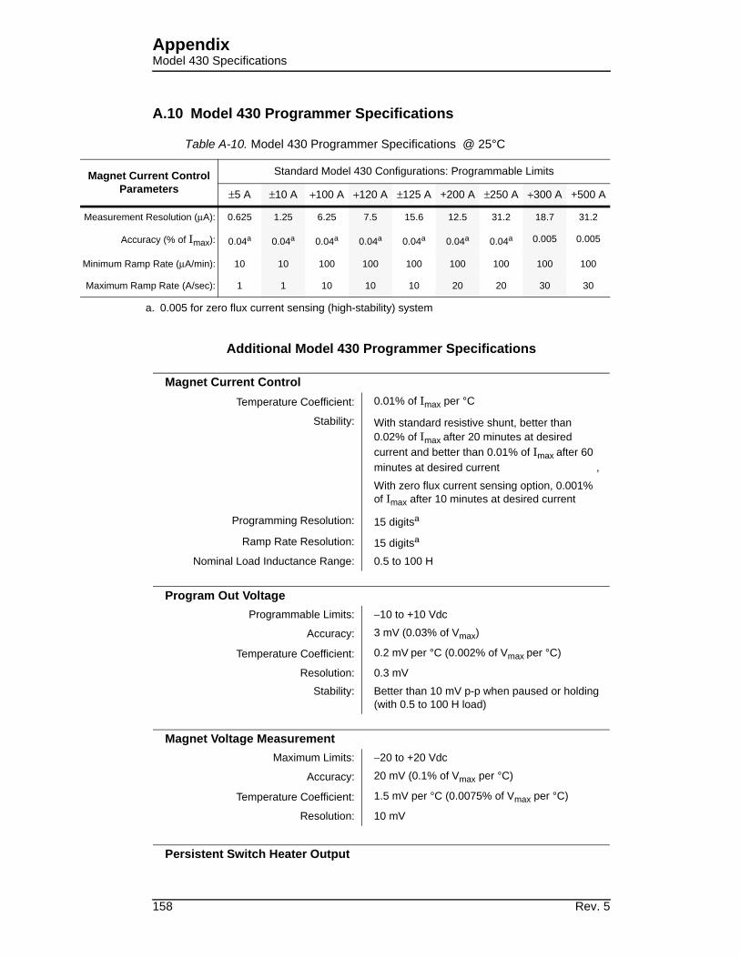
AppendixModel 430 Specifications
Magnet Cu
Para
Measurement
Accu
Minimum Ram
Maximum Ra
A.10 Model 430 Programmer Specifications
Additional Model 430 Programmer Specifications
Table A-10. Model 430 Programmer Specifications @ 25°C
rrent Control
meters
Standard Model 430 Configurations: Programmable Limits
±5 A ±10 A +100 A +120 A ±125 A +200 A ±250 A +300 A +500 A
Resolution (μA): 0.625 1.25 6.25 7.5 15.6 12.5 31.2 18.7 31.2
racy (% of Imax): 0.04a
a. 0.005 for zero flux current sensing (high-stability) system
0.04a 0.04a 0.04a 0.04a 0.04a 0.04a 0.005 0.005
p Rate (μA/min): 10 10 100 100 100 100 100 100 100
mp Rate (A/sec): 1 1 10 10 10 20 20 30 30
Magnet Current Control
Temperature Coefficient: 0.01% of Imax per °C
Stability: With standard resistive shunt, better than
0.02% of Imax after 20 minutes at desired
current and better than 0.01% of Imax after 60
minutes at desired current ,
With zero flux current sensing option, 0.001%
of Imax after 10 minutes at desired current
Programming Resolution: 15 digitsa
Ramp Rate Resolution: 15 digitsa
Nominal Load Inductance Range: 0.5 to 100 H
Program Out Voltage
Programmable Limits: −10 to +10 Vdc
Accuracy: 3 mV (0.03% of Vmax)
Temperature Coefficient: 0.2 mV per °C (0.002% of Vmax per °C)
Resolution: 0.3 mV
Stability: Better than 10 mV p-p when paused or holding
(with 0.5 to 100 H load)
Magnet Voltage Measurement
Maximum Limits: −20 to +20 Vdc
Accuracy: 20 mV (0.1% of Vmax per °C)
Temperature Coefficient: 1.5 mV per °C (0.0075% of Vmax per °C)
Resolution: 10 mV
Persistent Switch Heater Output
158 Rev. 5

AppendixModel 430 Specifications
Programmable Limits: 0.0 to 125 mA dc
Accuracy: 0.2 mA
Temperature Coefficient: 0.01 mA per °C
Maximum Compliance: 14 V
Resolution: 0.03 mA
Rampdown and Quench Inputs
Open Circuit Voltage: 5 Vdc ± 5%
Input Resistance: 10 k-ohm ± 1%
Quench Dry Contact Output
Maximum Switching Voltage: 60 Vdc
Maximum Switching VA: 10 VA
Maximum Switching Current: 500 mA, unless limited by VA rating
Galvanic Isolation: 125 Vdc
Power Requirements
Primary: 100-115 Vac or 200-230 Vac ±10%
50 / 60 Hz, 100 VA max., 30 W max.
Real-time Clock Backup Battery: 3 V CR2032 Lithium coin cell
Physical
Dimensions: 89 mm H x 483 mm W x 191 mm D
(3.5" H x 19" W x 10.75" D)
Weight: 8.5 lbm (3.9 kg)
Terminal Torque Limit: 48 lbf-in (5.4 N-m).
Environmental
Ambient Temperature: Operating: 0°C to 50°C (32°F to 122°F)
Non-operating: −20°C to 70°C (−4°F to 158°F)
Relative Humidity: 0 to 95%; non-condensing
Terminal Torque Limit: 48 lbf-in (5.4 N-m)
Standards
EMI/EMC Standards: EN 61000-4-2 EN 61000-4-3
EN 61000-4-4 EN 61000-4-5
EN 61000-4-6 EN 61000-4-8
EN 61000-4-11 EN 61000-3-2
EN 61000-3-3 EN 55011
Safety Standard: EN61010-1
Installation Category: Pollution Degree 2, Overvoltage Category II
as defined by IEC664
Rev. 5 159

AppendixModel 430 Specifications
a. Resolution of the IEEE 754 double-precision floating point type consisting of a
52-bit fraction and 11-bit exponent.
160 Rev. 5

AppendixPower Supply Details
OPERAT
Output Ra
steady-t not of the ltage supply.
A.11 Power Supply Details
This section provides the technical details of the individual power supply component of the AMI Model 4Q06125PS-430 Power Supply System.
Warning
All power supply parameters, both hardware and software, have been set by AMI, and no field adjustments or reconfiguration of the power supply should be attempted in the field.
Service must be referred to authorized personnel. Using the power supply in a manner not specified by AMI may impair the protection provided by the power supply. Observe all safety precautions noted throughout this manual.
Note
These individual power supply unit details are provided for reference only. Some of the basic power supply parameters given in this section will not apply as configured by the factory in the closed loop current feedback configuration under control of the AMI Model 430 Programmer. Refer to section A.10 on page 158 and System Specifications on page 8 for additional specifications relating to the overall system and individual components.
An AMI Model 430 Power Supply Programmer and Model 4Q06125PS Power Supply are configured to make up the 4Q06125PS-430 Power Supply System. The Model 4Q06125PS is a ±6 volt, ±125 ampere, 4-quadrant, voltage and current stabilized DC supply. Refer to section A.11.1 for additional electrical characteristics of the Model 4Q06125PS.
A.11.1 Model 4Q06125PS Electrical Specifications1
Table A-11 lists Model 4Q06125PS electrical specifications.
1. Details for the stand-alone units are provided for reference only.
Many of the basic power supply parameters will not apply in the
closed loop current feedback system application with the AMI Model
430 Programmer controlling current in the outer loop.
Table A-11. Model 4Q06125PS Electrical Specifications
Specification Rating / Description Condition
ING CHARACTERISTICS
nge
EO Max ±6 VdcWhen connecting active loads, the state voltage of the active load musexceed the maximum voltage ratingpower supply. Otherwise the overvoprotection will shut down the power
IO Max ±125 Adc
Rev. 5 161

AppendixPower Supply Details
Closed Lo
INPUT C
Voltage
Frequenc
Current
Power fac
Efficiency
Switching
EMC (Eleance
EMC imm
EMC emis
Leakage c
Insulation
OUTPUT
Type of st
Switching
Source adrange
Sink adjusurned to
op GainVoltage Channel 0.6
Current Channel 12.5
HARACTERISTICS
Nominal 230 VacSingle phase
Range 176 - 264 Vac
yNominal 50 - 60 Hz
>65 Hz, leakage exceeds specRange 47 - 65 Hz
176 Vac 9.5 AMaximum
264 Vac 6.4 A
tor 0.99 minimum Nominal output power, source
50% Minimum, source
frequency 50 KHz PFC Stage
ctromagnetic Compatibility) Compli-EN61326-1 (1997) Class A equipment
unity to:
ESD EN61000-4-2 Electrostatic discharge
Radiated RF EN61000-4-3 Radio Frequencies
EFT EN61000-4-4 Electrical fast transient/burst
Surges EN61000-4-5
Conducted RF EN61000-4-6
sions Conducted
EN61000-3-2 Harmonics
EN61000-3-3 Fluctuation & flicker
EN55011/CISPR110.15 to 30 MHz
Radiated 30 to 1000 MHz
urrent 3.5 mA 230 Vac, 47-63 Hz
coordination
InputInstallation Category II
Overvoltage Category II
OutputInstallation Category II
Overvoltage Category II
Pollution degree 2
CHARACTERISTICS
abilizer Voltage-current, 4-quadrant Switch mode
frequency 100 KHz Output Stage
justment Voltage -6 V to +6 V0 to 50°C
Current -125 A to +125 A
tment rangeVoltage -6 V to +6 V 0 to 50°C, recuperated energy is ret
lineCurrent -125 A to +125 A
Table A-11. Model 4Q06125PS Electrical Specifications (Continued)
Specification Rating / Description Condition
162 Rev. 5

AppendixPower Supply Details
Voltage st(voltage m
Error sens
Transient voltage m
Isolation
Output Stuit
Input Stag
uit
Small signBandwidth
ating
Rise/Fall
d from g
to 90%,
GENERA
Temperat
Cooling
Humidity
Shock
Vibration
Altitude
Safety Ce
Dimensio
Weight
ConnectioControls
abilization ode)
Source effect ±3 mV Min-max input voltage
Load effect ±6 mV 0-100% load current
Time effect (drift) ±3 mV 0.5 through 24 hours
Temperature ±3 mV/°C 0 to 50°C
Ripple and noise ±120 mV p-p Includes switching noise
ing 0.1 V per wire Above rated output
recovery in ode
Maximum excursion ±300 mV Nominal voltage, 50% load step
Recovery time 200 μsec Return within 0.1% of set voltage
Voltage 100 V Output to ground
age Protection Output overvoltage/overcurrentRecover by setting input power circbreaker to off, then on
e Protection (PFC)Internal fault
Recover by setting input power circbreaker to off, then on
Input circuit breaker overcurrent Trips circuit breaker to shut off unit
al Voltage channel 2 kHz minimum Into nominal resistive load 10% of r
Current channel 800 Hz minimum Into short circuit, 10% of rating
time
Voltage channel 250/250 μSecInto nominal resistive load, measure10 to 90%, from 0 to ±100% of ratin
Current channel 0.5/0.5 mSecInto short circuit, measured from 10from 0 to ±100% of rating
L (ENVIRONMENTAL) CHARACTERISTICS
ureOperating 0 to +50°C Full rated load
Storage -20 to +85°C
Two internal fans Exhaust to the rear
0 to 95% RH Non-condensing
20 g 11 mS ±50% half sine Non-operating
5-10 Hz: 10 mm double amplitude3 axes, non-operating
10-55 Hz: 2 g
sea level to 10,000 feet Consult factory for derating.
rtification AC power EN 61010-1 CE Mark
nsEnglish 5.25” X 19" X 21.5"
H X W X DMetric 133.3 mm X 482.6 mm X 546.1 mm
English 53 lbs
Metric 24.1kg
ns and
Source power 3-pin IEC connector
Configured by AMI Factory
Load connections Nickel-plated copper bus bars
Sensing OutputTerminal Block
7-pin terminal block
Analog I/O control port 15-pin D female
Table A-11. Model 4Q06125PS Electrical Specifications (Continued)
Specification Rating / Description Condition
Rev. 5 163

AppendixPower Supply Details
CrowbarCharacter
is an D is on) er.
A.11.2 Model 4Q06125PS Dimensional Specifications
Figure A-1 and Figure A-2 show outline drawings of the Model 4Q06125PS with dimensions.
istics
Maximum current: 150 A
Short-circuits the output when thereinternal fault (front panel FAULT LEor when there is a loss of input pow
Maximum voltage 48 V
Contact resistance 0.3 milli-ohms @100 A (typical)
On/off timing 25 mS (typical)
Table A-11. Model 4Q06125PS Electrical Specifications (Continued)
Specification Rating / Description Condition
Figure A-1. 4Q06125PS Outline Drawing, Front and Rear Views
164 Rev. 5
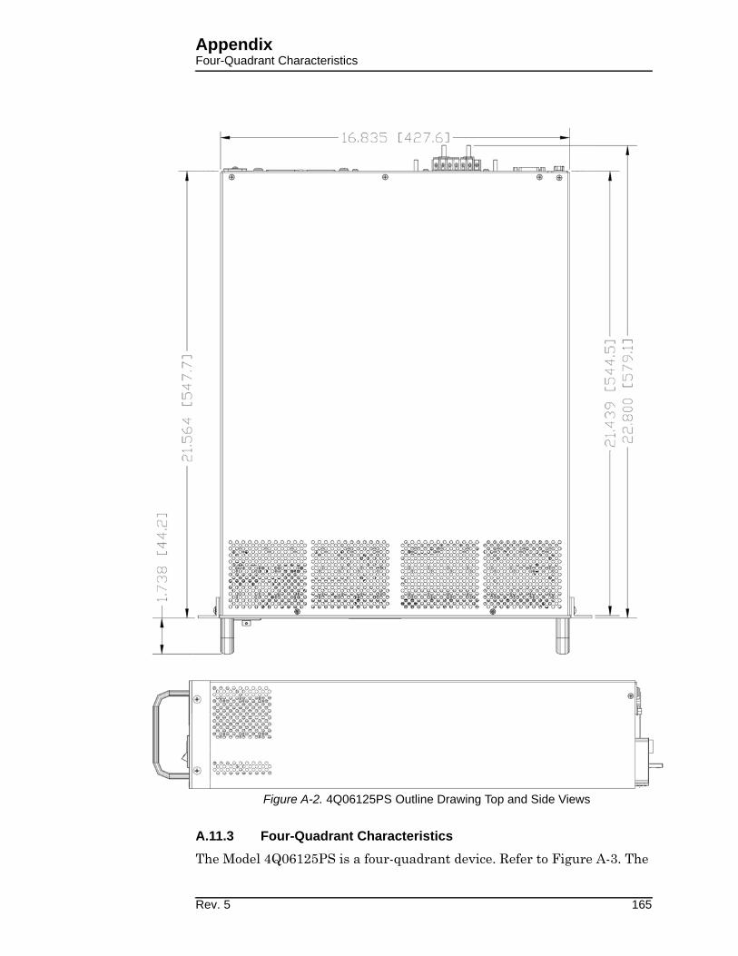
AppendixFour-Quadrant Characteristics
A.11.3 Four-Quadrant Characteristics
The Model 4Q06125PS is a four-quadrant device. Refer to Figure A-3. The
Figure A-2. 4Q06125PS Outline Drawing Top and Side Views
Rev. 5 165

AppendixRemote Computer Communication (RS-232)
supply operating as a source delivers energy into a load, and as a sink it operates as an electronic load, absorbing and dissipating energy from the load. To minimize energy dissipation, the Model 4Q06125PS employs energy recuperation, where energy from an active load is passed backward through the output circuit and the bidirectional input power factor correcting circuit to the power line. This technology allows high power levels using switch-mode technology while maintaining high efficiency and reduced size and weight.
Figure A-3. Four-Quadrant Supply Output Characteristics
A.12 Remote Computer Communication with the Model 430
A.12.1 Communication via RS-232
1. Using serial a null modem cable, connect the DB9 RS-232 connector on the rear of the Model 430 Programmer to a serial connector on the computer.
166 Rev. 5

AppendixRemote Computer Communication (RS-232)
2. Start a terminal emulator program on the remote computer. As an example, this procedure will use the HyperTerminal program running on a Windows machine.
3. Choose File > New Connection and in the resulting screen field, enter a name for the connection. Click on OK.
4. From the Connect using: pull-down menu, select the appropriate COM port and click OK.
Rev. 5 167

AppendixRemote Computer Communication (RS-232)
5. Edit the communication parameters per section 4.3 on page 106 and click OK.
6. Choose File > Properties and then click on the Settings tab.
7. Click on the ASCII Setup... button and check the Send line ends with line feeds box and the Echo typed characters locally box in the ASCII Sending area. Click on OK and then OK on the next screen.
168 Rev. 5

AppendixRemote Computer Communication (Ethernet)
8. Type *IDN? to test the connection. The Model 430 Programmer should respond with “AMERICAN MAGNETICS, INC., MODEL 430,X.X” where X.X is the firmware version.
9. Issue commands as desired. See “Remote Interface Reference” on page 93.
A.12.2 Communication via Ethernet
1. Connect the Model 430 Programmer RJ-45 Ethernet port either directly to a host computer or through a computer network on which the host computer resides:
a. For a host computer on a network, connect a standard Ethernet cable between the Model 430 and the network.
b. For a direct hardwired connection between the Model 430 and a host computer, use a “null-modem” or “crossover” Ethernet cable connected from the Model 430 directly to the host computer
2. Turn on the Model 430 and press <ENTER> at the “Turn on power supply . . .” prompt.
3. Press MENU to enter the menu system.
4. Use < >/< > to navigate to the Net Settings submenu and press <ENTER>.
5. Use < >/< > as necessary to navigate to Addr Assignment (Present).
Rev. 5 169

AppendixRemote Computer Communication (Ethernet)
Note
The Addr Assignment (Present) must show “DHCP” as originally set by AMI.
Note
In the following step, the IP Address is the four part number separated by periods (.), and will change with each Ethernet connection.
6. Use < >/< > to locate IP Address (Present), similar to that shown in Figure 1.
7. Make note of the IP Address (Present).
8. Start a terminal emulation program on the remote computer. As an example, this procedure will use the HyperTerminal program running under Windows XP.
9. Choose File > New Connection and in the resulting screen field, enter a name for the connection. Click OK - the Connect to screen will appear.
+0.00 A — IP Address (Present)+0.00 Vs 169.254.243.199 (DHCP)
170 Rev. 5

AppendixRemote Computer Communication (Ethernet)
10. In Host address, enter the Model 430 Programmer IP address as determined previously in step 2.
11. Enter 7180 in the Port Number field.
12. From the Connect using pull-down menu, select TCP/IP (Winsock) and click OK.
13. The computer will connect with the Model 430 Programmer and display a welcome screen.
14. Choose File > Properties and then click on the Settings tab.
Rev. 5 171
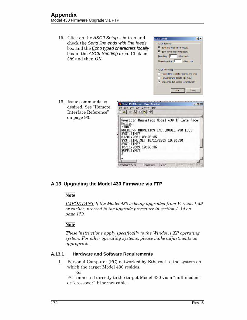
AppendixModel 430 Firmware Upgrade via FTP
15. Click on the ASCII Setup... button and check the Send line ends with line feeds box and the Echo typed characters locally box in the ASCII Sending area. Click on OK and then OK.
16. Issue commands as desired. See “Remote Interface Reference” on page 93.
A.13 Upgrading the Model 430 Firmware via FTP
Note
IMPORTANT If the Model 430 is being upgraded from Version 1.59 or earlier, proceed to the upgrade procedure in section A.14 on page 179.
Note
These instructions apply specifically to the Windows XP operating system. For other operating systems, please make adjustments as appropriate.
A.13.1 Hardware and Software Requirements
1. Personal Computer (PC) networked by Ethernet to the system on which the target Model 430 resides,
or PC connected directly to the target Model 430 via a “null-modem” or “crossover” Ethernet cable.
172 Rev. 5
AppendixModel 430 Firmware Upgrade via FTP
2. The Model430.exe upgrade file extracted from the zip file (typically of the same name) provided by AMI.
3. FileZilla1 or other appropriate FTP Client installed on the PC. For this procedure an FTP client called FileZilla is used.
A.13.2 Preparation
1. Install FileZilla or another appropriate FTP Client on the PC that will used for the upgrade.
2. The AMI Model 430 can be upgraded through a file server, or similar network, or via direct Ethernet connection to the PC:
a. Via Network:
(1.) Make a new “Upgrade” folder located in an appropriate location on the file server.
(2.) Extract and save the AMI-supplied upgrade-file, Model430.exe, to the new folder.
(3.) Ensure that the PC is connected to the network.
(4.) Ensure the Model 430 is connected to the network via standard Ethernet cable.
b. Direct PC-to-Model 430:
(1.) Make a new “Upgrade” folder located in an appropriate location on the PC.
(2.) Extract and save the AMI-supplied upgrade-file, Model430.exe, to the new folder.
(3.) Connect the PC to the Model 430 using a “null-modem” Ethernet cable (also referred to as an Ethernet “cross-over” cable).
3. Turn on the Model 430 and press <ENTER> at the “Turn on power supply . . .” prompt.
4. Press MENU to enter the menu system.
5. Use < >/< > to navigate to Net Settings submenu and press <ENTER>.
6. Use < >/< > as necessary to navigate to Addr Assignment (Present).
1. Available free at http://filezilla-project.org/
Rev. 5 173
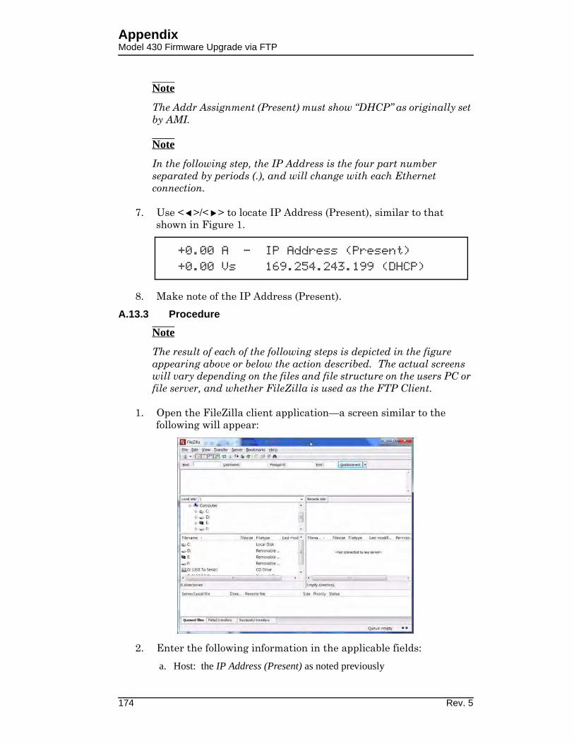
AppendixModel 430 Firmware Upgrade via FTP
Note
The Addr Assignment (Present) must show “DHCP” as originally set by AMI.
Note
In the following step, the IP Address is the four part number separated by periods (.), and will change with each Ethernet connection.
7. Use < >/< > to locate IP Address (Present), similar to that shown in Figure 1.
8. Make note of the IP Address (Present).
A.13.3 Procedure
Note
The result of each of the following steps is depicted in the figure appearing above or below the action described. The actual screens will vary depending on the files and file structure on the users PC or file server, and whether FileZilla is used as the FTP Client.
1. Open the FileZilla client application—a screen similar to the following will appear:
2. Enter the following information in the applicable fields:
a. Host: the IP Address (Present) as noted previously
+0.00 A — IP Address (Present)+0.00 Vs 169.254.243.199 (DHCP)
174 Rev. 5

AppendixModel 430 Firmware Upgrade via FTP
b. User Name: model430admin
c. Password: supermagnets
d. Port: 21
3. Click the Quickconnect button to connect to the Model 430 – the Remote Site section of the screen will populate.
4. On the Local Site (left side representing your PC or server file system), navigate to the folder containing the Model430.exe
Rev. 5 175

AppendixModel 430 Firmware Upgrade via FTP
upgrade file (the folder name will be that which was previously given the new “upgrade” folder.).
5. Double-click to open the “upgrade” folder on the Local Site (left side) of the screen – the Model430.exe file will appear.
176 Rev. 5

AppendixModel 430 Firmware Upgrade via FTP
6. On the Remote Site (right side representing the Model 430 files), select the Upgrade folder.
7. Double-click the Upgrade folder to open it (the folder will be empty).
Rev. 5 177

AppendixModel 430 Firmware Upgrade via FTP
8. Select the Model430.exe file from the Local Site (left side) and drag it to the open Upgrade folder on the Remote Site (right side)1.
9. Turn off the Model 430.
10. Close the FTP program.
Note
This completes the firmware upgrade. When the Model 430 power is turned on again after powering down, the firmware will automatically upgrade based on the Model430.exe file just placed in its Upgrade folder. View the “Loading. . . . .” screen as the Model 430 is “booting” up: the new Firmware Version will momentarily2 be displayed.
11. Reboot the Model 430 Programmer by switching the power switch on the front panel off for 10 seconds and then turning the switch back on.
12. Verify that after approximately 20 seconds, the Model 430 display briefly shows the new (upgraded) firmware version3:
1. Alternatively, copy Model430.exe from the Local Site and paste it to
the open folder on the Remote Site.
2. Display time may vary depending on network speed - refer to
section 5.2.18 on page 142.
3. Version 1.59 is used only for purposes of this example.
AMI Model 430 ProgrammerFirmware Version: 1.61
178 Rev. 5
AppendixModel 430 Firmware Upgrade via Flash Card Reader
A.14 Upgrading the Model 430 Firmware via Flash Card Reader
Note
These instructions are intended primarily for a Model 430 being upgraded from Version 1.59 or earlier. If the current version is v1.60 or later, upgrade should be performed via FTP according to section A.13 on page 172.
Note
These instructions apply specifically to the Windows XP operating system. For other operating systems, please make adjustments as appropriate.
This is a one-time only procedure - future upgrades will be handled via the Ethernet communications connection on the rear panel of the instrument. An operating system file on the Compact Flash (CF) card mounted inside the Model 430 must be updated to enable the new web server functionality. The file is not accessible via FTP which means the Model 430 cover must be removed, the CF card removed, and the files updated using a CF card reader. Once this upgrade is completed, the CF card should not have to be removed in order to perform future upgrades.
A.14.1 Hardware and Software Requirements
1. The zip file, Model 430 flash card update.zip, is required for this upgrade; the zipped files are to be extracted and copied to the CF card.
2. Host computer on a network to which the Model 430 can be connected by standard Ethernet cable
or Host computer that can be connected directly to the target Model 430 via an Ethernet “null-modem” or “crossover” cable.
3. Standard Ethernet cable or Ethernet “null-modem” cable, as appropriate.
A.14.2 Preparation
Complete the following in preparation for the upgrade.
1. Power down and unplug the Model 430.
2. Remove the cover from the Model 430 as follows:
a. Remove the screws securing the cover on the back edges of the instrument (two near each side of the instrument).
b. Remove the screws securing the cover just behind the front panel (two on each side of the instrument).
3. Remove the CF card1 from the Model 430 as follows:
Rev. 5 179

AppendixModel 430 Firmware Upgrade via Flash Card Reader
a. Grasp the edges of the card with the thumb and forefinger.
b. Gently pull outward to remove the card.
4. Insert the CF card into a CF reader attached to (or internal to) a host computer.
5. Browse to My Computer on the host computer to verify the CF card is visible as a drive.
A.14.3 Procedure
The following steps provide detailed instructions to complete the upgrade.
1. Copy the zip file Model 430 flash card update.zip to a location on the host computer – for example, C:\Model 430\Model 430 v1.60 Upgrade:
2. Double-click the zip file to open it – the following or similar screen should appear with the files shown:
1. The Compact Flash card is located at the front right corner of the
Model 430 motherboard.
180 Rev. 5

AppendixModel 430 Firmware Upgrade via Flash Card Reader
3. Choose File > Extract All… to start the extraction wizard:
4. Click Next until prompted with Select a Destination:
5. Browse to My Computer and choose the top level (root) of the drive associated with the CF card (for example E:\ or G:\) and select Next.
Rev. 5 181

AppendixModel 430 Firmware Upgrade via Flash Card Reader
6. When prompted with the Confirm File Replace dialog, select Yes To All.
7. When the extraction process concludes, select Finish.
8. Close all open windows for the CF drive.
9. Use the Safely Remove Hardware icon in the tool tray to eject (unmount) the CF card from the host computer.
10. Remove the CF card from the card reader.
11. Re-install the CF card in the Model 430 - ensure the card is seated properly.
12. Re-install the cover on the Model 430 using the previously removed screws.
Note
The Model 430 and the host computer must share the same network address scheme and be attached to the same physical network in the following process.
13. Verify that the web interface is functioning correctly as follows:
a. Connect the Model 430 to the host computer using one of the following two methods:
(1.) Via Ethernet cable to the same physical network as the host computer.
(2.) Via “crossover” or “null modem” Ethernet cable direct-ly to the host computer’s Ethernet port.
b. Plug in and power up the Model 430.
c. As the Model 430 boots up, watch the front display and verify that it shows Firmware Version: 1.621 (or other version being upgraded to).
d. Press <ENTER> at the Turn on power supply prompt.
e. Using the Model 430 menu system, Menu > Net Settings > IP Address (Present), determine the IP Address of the Model 430.
f. Open a web browser on the host computer and type the IP address2 of the Model 430 into the address bar.
1. Display time may vary depending on network speed - refer to
section 5.2.18 on page 142.
182 Rev. 5

AppendixModel 430:Remote Control Application
g. The following screen should appear:
14. This completes the installation and verification of the Model 430 Firmware Upgrade.
A.15 Model 430 Remote Control Application
Model 430 can be accessed via a network connection1,2 with fully functional control3. This is accomplished through the Ethernet connection on the rear panel using TCP/IP protocol via a host computer. The connection and control can be established through a locally connected computer or remotely through a network or even the Internet; the human/machine interface is a web browser depiction of the Model 430.
The browser-displayed Model 430 Programmer can be used to control any Model 430 front panel hardware device except the power switch. Also, any setting changes made at the actual Programmer will be reflected on the displayed version.
The Model 430 Programmer RJ-45 Ethernet port must be connected either directly to a host computer or through a computer network on which the host computer resides:
2. In the form http://xxx.xxx.xxx.xxx, where the "xxx" values match the
IP Address (Present) of the Model 430.
1. The browser must be Java-Applet capable. If the browser displays a
message indicating the required Java plug-in needs to be installed,
please follow the screen instructions to download and install the
plug-in on the browser of host computer.
2. Third party remote software, such as National Instruments LabView,
can also be used.
3. With the exception of the Power On/Off switch.
Rev. 5 183

AppendixModel 430:Remote Control Application
1. For a host computer on a network, connect a standard Ethernet cable between the Model 430 and the network.
2. For a direct hardwired connection between the Model 430 and a host computer, use a “null-modem” or “crossover” Ethernet cable connected from the Model 430 to the host computer
3. Once connected, plug in and power up the Model 430.
4. Press <ENTER> after responding to the “Turn on power supply . . .” prompt.
Note
Allow about 90-seconds (from power-up) for the TCP/IP link between the Model 430 and host computer to be established.
In order to access the Model 430 using this application, either the Model 430 System Name or IP Address must be known. The System Name should be available from the Model 430 configuration documentation; the IP Address can be determined after Model 430 power-up. The following examples illustrate how the System Name or IP Address may be determined using the Model 430 menu system:
1. IP Address: Menu > Net Settings > IP Address (Present).
2. System Name: Menu > Net Settings > System Name (Present).
Open a web browser on the host computer. In the address field, type “http://” followed by either the IP Address or System Name, and press <ENTER>. For example:
Note
If using the System Name, allow about 90-seconds after power-up before typing the http address into the browser and pressing
+0.00 A — IP Address (Present)+0.00 Vs 169.254.91.47 (DHCP)
+0.00 A — System Name (Present)+0.00 Vs A10123_X-AX
Figure A-4. http:// - IP Address or System Name Entry
184 Rev. 5

AppendixModel 430:Remote Control Application
<ENTER>. If entered too soon, re-enter or click the browser “refresh” icon.
The following initial screen should be appear.
The AMI Model 430 Remote Control Application is the primary feature of this screen. When selected, a view of the Model 430 being controlled with the web browser will appear (under the Operator Panel tab).
All functions, except the Power On/Off Switch, are active and operate (using the computer mouse1) exactly as the hardware Model 430.
The initial screen also includes links to the Model 430 Manual in PDF form along with Frequently Asked Questions relating to the Model 430 application (all stored in the Model 430 firmware). There are links to the AMI website and an e-mail form for contacting AMI Customer Support. The Command Interface is available under the tab of the same name, and operates exactly as described in “Remote Interface Reference” on page 93.
1. To rotate the Fine Adjust Knob (after enabling with the SHIFT key),
just click and drag in the desired direction.
Figure A-5. Initial Screen for Browser Access of the Model 430
Rev. 5 185

AppendixModel 430IP
A.16 Model 430IP Power Supply Programmer1
With no front panel controls except the power On/Off switch, the Model 430IP is designed for fully functional control solely through a web browser2,3 using TCP/IP via the rear panel Ethernet connection. Operation is very similar to that of the Model 430 Remote Control Application as described in section A.15 on page 183.
Control can be established through a locally connected computer or remotely through a network or even the Internet; the human/instrument interface is a web browser depiction of the Model 430.
Connect the Model 430IP Programmer RJ-45 Ethernet port either directly to a host computer or through a computer network on which the host computer resides:
1. For a host computer on a network, connect a standard Ethernet cable between the Model 430 and the network.
2. For a direct hardwired connection between the Model 430 and a host computer, use a “null-modem” or “crossover” Ethernet cable connected from the Model 430 to the host computer
Once connected, plug in and power up the Model 430.
1. Requires Model 430 version 1.60 or later firmware.
2. The browser must be Java-Applet capable. If the browser displays a
message indicating the required Java plug-in needs to be installed,
please follow the screen instructions to download and install the
plug-in on the browser of host computer.
3. Third party remote software, such as National Instruments LabView,
can also be used.
Figure A-6. Model 430IP Front Panel
Figure A-7. Browser Depiction of the Model 430
186 Rev. 5
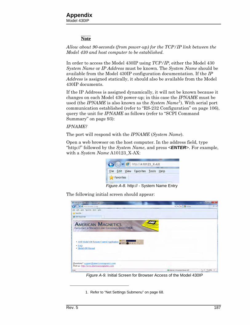
AppendixModel 430IP
Note
Allow about 90-seconds (from power-up) for the TCP/IP link between the Model 430 and host computer to be established.
In order to access the Model 430IP using TCP/IP, either the Model 430 System Name or IP Address must be known. The System Name should be available from the Model 430IP configuration documentation. If the IP Address is assigned statically, it should also be available from the Model 430IP documents.
If the IP Address is assigned dynamically, it will not be known because it changes on each Model 430 power-up; in this case the IPNAME must be used (the IPNAME is also known as the System Name1). With serial port communication established (refer to “RS-232 Configuration” on page 106), query the unit for IPNAME as follows (refer to “SCPI Command Summary” on page 93):
IPNAME?
The port will respond with the IPNAME (System Name).
Open a web browser on the host computer. In the address field, type “http://” followed by the System Name, and press <ENTER>. For example, with a System Name A10123_X-AX:
The following initial screen should appear:
1. Refer to “Net Settings Submenu” on page 68.
Figure A-8. http:// - System Name Entry
Figure A-9. Initial Screen for Browser Access of the Model 430IP
Rev. 5 187

AppendixModel 430IP
The AMI Model 430 Remote Control Application is the primary feature of this page. When selected, a view of the Model 430 being controlled with the web browser will appear (under the Operator Panel tab).
All functions, except the power switch, are active and operate (using the computer mouse1) to control the hardware Model 430.
The initial screen also includes links to the Model 430 Manual (in PDF form) along with Frequently Asked Questions relating to the Model 430. There are links to the AMI website and an e-mail form for contacting AMI Customer Support. Also available is the Command Interface (under the tab of the same name) which operates exactly as described in “Remote Interface Reference” on page 93.
1. To rotate the Fine Adjust Knob (after enabling with the SHIFT key),
just click and drag in the desired direction.
Figure A-10. Browser Control of the Model 430IP
188 Rev. 5
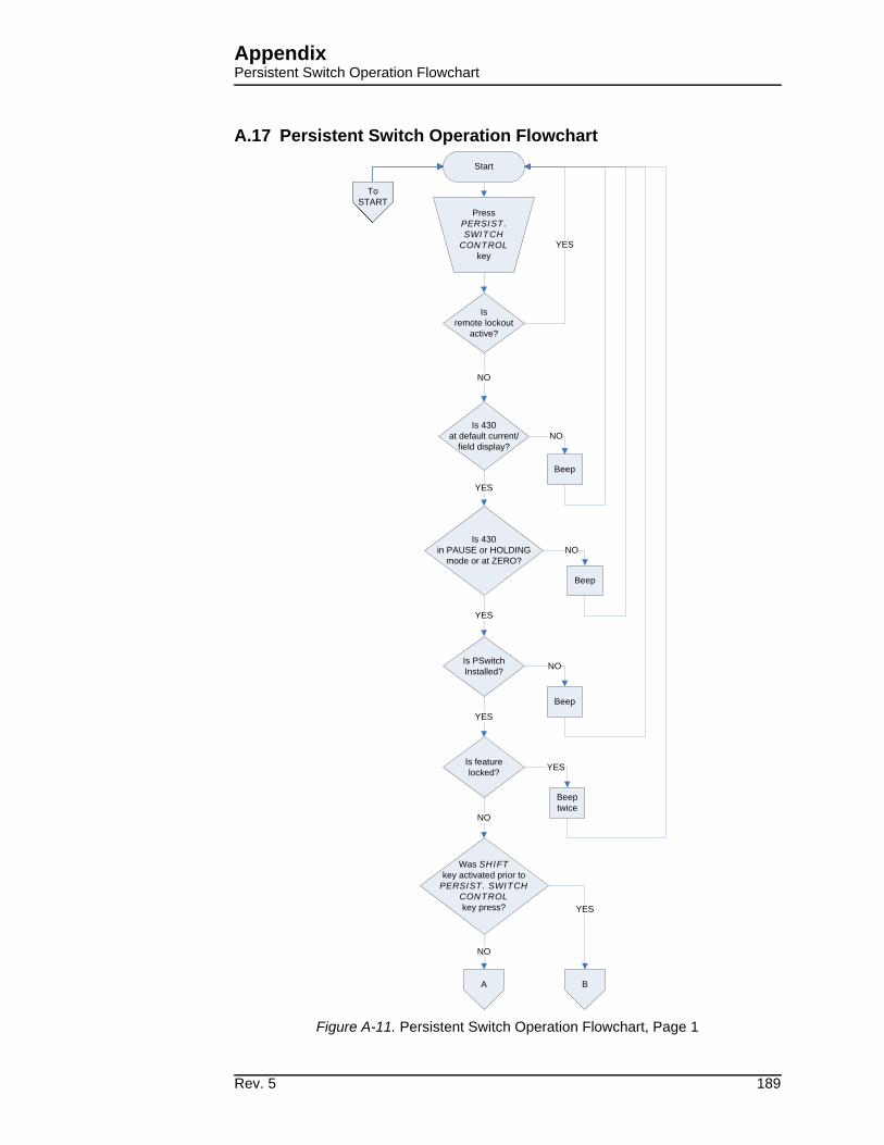
AppendixPersistent Switch Operation Flowchart
A.17 Persistent Switch Operation Flowchart
YES
Start
Press PERSIST.
SWITCH
CONTROL
key
Was SHIFT
key activated prior to PERSIST. SWITCH
CONTROL
key press?
NO
YES
Isremote lockout
active?
Beep
YES
Is 430in PAUSE or HOLDING
mode or at ZERO?
Beep
NO
YES
To START
To START
To START
Is 430at default current/
field display?
NO
NO
Is PSwitch Installed?
Beep
NO
Is feature locked?
YES
NO
Beeptwice
YES
A B
To START
To START
To START
To START
To START
To START
Figure A-11. Persistent Switch Operation Flowchart, Page 1
Rev. 5 189
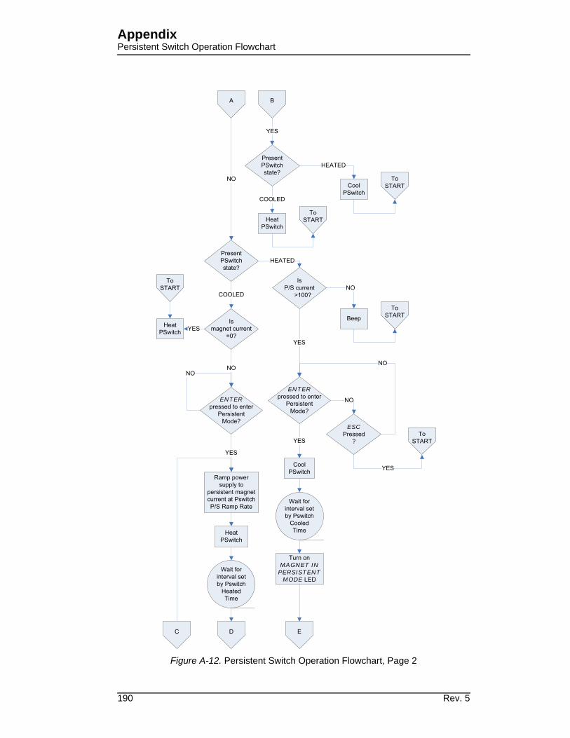
AppendixPersistent Switch Operation Flowchart
ENTER
ESC
ENTER
MAGNET IN
PERSISTENT
MODE
Figure A-12. Persistent Switch Operation Flowchart, Page 2
190 Rev. 5

AppendixPersistent Switch Operation Flowchart
Figure A-13. Persistent Switch Operation Flowchart, Page 3
Rev. 5 191

AppendixPersistent Switch Operation Flowchart
192 Rev. 5

Index
1 Index
Aabbreviations and acronyms 154
absolute limits 90
AMI internet e-mail address 143
AMI web address 143
Bbeep
editing PSw P/S ramp rate 34
editing ramp rate 33
error messages 130
incorrect password 61, 68
locked command 61
mismatch between pswitch and power
supply currents 83
on initiate ramping 30
on select supply 45
on setting current limit below TARGET
FIELD SETPOINT 53
on setting magnet current rating below
TARGET FIELD SETPOINT
52
parameter outside range 26, 90
pswitch 29
pswitch did not properly transition to the
superconducting state 80
boot 178, 182
brightness 59
Ccable interconnections. See interconnects
cancelling entry 26
cleaning - see routine maintenance
closed-loop control 3
coil constant
acceptable values 51
calculate 51
defined 50
lock 65
command
error messages 130
device errors 132
query errors 131
in remote control application 185
overview 100
command handshaking 104
condition register 100
event register 101
SCPI introduction 100
standard event register 103
status byte 101
status system 100
status system diagram 101
reference
locking 115
protection commands 115
quench control 126
ramping commands 120
ramping states 124
setup commands 110
status commands 109
switch heater control 125
system commands 108
trigger commands 129
trigger functions 128
summary
conventions 93
protection commands 95
protection configuration queries 96
quench state 99
ramp configuration 98
ramping state 99
setup configuration commands 94
setup configuration queries 95
switch heater 99
system-related commands 93
trigger control 99
compatible power supplies 50
configuration
system
four-quadrant high-current supply
13
general 13
master supply 7
non-standard 16
power lead size 13
slave supply 7
connectors
analog I/O 16
aux input 152
Ethernet communication 16, 153
LHe level/temp 13, 16, 146
magnet station 13, 16, 145
program out 16, 148
quench I/O 16, 149
RJ-45 - see Ethernet
RS-232 serial communication 16,
153
shunt terminals 147
system interconnect 13
current limit 19, 31, 33, 35, 37, 38,
43, 52, 61, 75, 77, 113,
124, 125
current limit example 52
current limit symmetry 53
current transducer
current direction 13
in dual quadrant system 9
in four-quadrant system 9
Ddata logging 128
de-energizing the system 22
default display modes 22
default password 61
default settings 90
Rev. 5 193

Index
DHCP 70, 72, 170, 174
diode
light emitting - see LED
display
asterisk 25, 28
brightness 59
current 19
field / current 23
field units 23
magnet quench indicator 24
mode status indicators 24
up/down arrow 27
voltage 24, 39
display brightness 59
Eencoder - see fine adjust knob
energizing the system 21
energy absorber
lock 67
present 58
energy recuperation 166
entering values 25
error messages 130
ESD precautions 135
Ethernet
cable 169, 184, 186
configuration
connector 107, 153, 169
termination characters 107
null-modem/crossover cable 169,
172, 184, 186
port 169, 183, 186
slow connection 142
example
current limit setup 53
ethernet communication setup 169
magnet specification sheet 73
Model 430 IP operation 186
Model 430 remote control application
183
power supply outputs 46
ramp rate menus 33
ramping functions 85
RS-232 communication setup 166
setup 72
system setup 72
external quench detect 57, 58
external rampdown 58, 67, 88, 89,
90, 120, 123, 124
external rampdown input 150
FFAILURE TO LOAD message 21, 137
field display 23
field units 60
fine adjust knob
coil constant 50
current limit 53
custom ps
max output current 48
max output voltage 47
min output current 47
min output voltage 47
displayed up/down arrow 27
enter key vs. esc. key 27
general description 26
immediate affect on the system 27
lock/unlock 65
magnet current rating 52
pswitch cooled time 56
pswitch cooling gain 57
pswitch current 55
pswitch heated time 56
pswitch power supply ramp rate 57
quench rate 60
ramp rate 33
shift key 39
slow/very fine resolution 27
stability setting 49
target current in HOLDING mode 77
to adjust numeric values 26
velocity sensitive 27
voltage limit 36
firmware upgrade
via flash card reader 179
via FTP 172
firmware version screen 142
four-quadrant operation 9, 46, 165
ftp client 174
fuses 137
HHyperTerminal 167
Iinductance, calculate 53
installation
earth ground 11
magnet system characteristics 12
mounting 11
power 12
unpacking 11
IP Address 69, 70, 71, 72, 106,
107, 142, 155, 170, 171,
174, 182, 183, 184
Kkeys
arrows 28
enter 25, 42
esc 26, 42
ESCape 28
fine adjust 27
manual control 75
menu 28
persistent switch control 29
ramp / pause 31
194 Rev. 5
Index
ramp rate 33
ramp to zero 31
ramp/pause 75
shift 27
shift persistent switch control 29
target field setpoint 31
voltage limit 36
LLED
current leads energized 41
definition 156
field at target 19, 40, 89
magnet in persistent mode 29, 40,
77, 79, 84, 89, 126
magnet quench 41, 86
power-on 40
shift 32
limit example 53
load submenu
calculate inductance 53
coil constant 50
current limit 52, 53
enable external rampdown 58
enable quench detect 57, 58
example limits 53
pswitch cooling gain 57
pswitch cooling time 56
pswitch current 55
pswitch current detect 54
pswitch heated time 55
pswitch installed 54
pswitch ramp rate 56
stability setting 48
locked 60, 67
loop gain 49
Mmagnet current
drifts while PSwitch cooling 142
oscillating 138
rating 31, 33, 35, 37, 38, 51,
52, 66
viewing established persistent current
31, 82
magnet specs 73
menu
cursor 27
navigation 27, 42
structure diagram 43
menus
load submenu 48
misc submenu 59
net settings submenu 68
net setup submenu 70
supply submenu 43
misc submenu
coil constant lock 65
current limit lock 65
display brightness 59
display brightness lock 67
external rampdown lock 67
field / current lock 64
field units 60
field units lock 64
fine adjust lock 65
increment / decrement field lock 63
mag current rating lock 66
net setup lock 67
persistent switch settings lock 66
power supply lock 63
pswitch control lock 62
quench detect lock 66
quench rate 60
quench rate lock 66
ramp / pause lock 62
ramp rate time units 59
ramp segments 59
ramp settings lock 62
reset quench lock 63
settings password lock 67
settings protection 60
stability settings lock 64
target field setpoint lock 62
voltage limit lock 63
voltmeter lock 65
Vs / Vm lock 64
Model 430
appears to lock up 142
remote control application 183
Model 430IP 186
Nname, system 184
net settings submenu
address assignment 69
gateway address 70
IP address 69
subnet mask 69
system name 69
net setup submenu
gateway IP address 71
IP address assignment 70
subnet mask 71
system IP address 71
null-modem/crossover cable
Ethernet 169, 172, 184, 186
RS-232 106, 166
Ooperating modes
four-quadrant 9
operating voltage, changing 12
operation 21
Rev. 5 195

Index
operational limits 90
Ppassword 61, 67
persistent mode
entering 78
exiting 81
viewing established magnet current 31,
82
persistent switch
abbreviations 156
beep 29
control 77
cooled time 27, 29, 30, 54, 56,
79, 86, 91
cooling 24, 30, 56, 57, 76, 79,
84, 142
cooling gain 27, 30, 54, 57, 91,
142
current 55
current detect 54
defaults
cooling gain 30
cooling period 30
heating period 30
heated time 27, 30, 54, 55, 78,
80, 83, 91
heating 12, 24, 30, 40, 56, 76,
78, 85, 89, 90
heating current 27, 30, 54, 55
installed? 54, 95, 113
not installed on magnet 16, 49
ramp rate 19, 27, 29, 30, 34,
54, 56, 79, 82, 114
settings lock 66, 119
power supply
4-quadrant 13
compatibility 45
displayed current 19
displayed voltage 24
general description 3
operating characteristics 9
precise control of current 3
ps unit details 161
ps unit front panel layout 7
routine maintenance 135
system integral components 1
system interconnects 13
system rack layout 4
system terminology 154
system troubleshooting 135
voltage-voltage mode 3
power up/down sequence 21
powering system off 22
powering system on 21
power-up test 18
programmed current 31
protection password 60, 67
pswitch - see persistent switch
Qquench detection 60, 86
disabling 57, 88
enabling 57
external in/out 87, 149
indicator 24
switch failure 88
quench rate 60
quench, magnet xvi
Rramp modes 76
ramp rate time units 59
ramp segments 59
rampdown, external - see external rampdown
ramping
automatic ramping 76
basic relationships 74
direct current manipulation 77
example 85
manual increment or decrement 76
mode symbols 24
ramp to zero 77
segmented 33, 34, 36, 59, 62,
75, 77, 98, 116, 120,
121, 122, 123, 124,
151
states 75, 125
remote control application
command interface 185
controls Model 430 183
frequently asked questions 185
IP address 184
links 185
mirrored control 183
system name 184
view of Model 430 185
web browser depiction 183
remote interface reference - see command
return authorization 143
RJ-45 connector - see Ethernet
routine maintenance 135
RS-232 configuration
connector 106, 153, 154, 166
null-modem/crossover cable 106,
166
parameters 106
termination characters 106
Ssafety
cryogens xiv
equipment xvi
legend xvii
quenches xvi
196 Rev. 5

Index
segmented ramping 59
see ramping, segmented
settings 60
settings password 67
settings protection 60
setup
example 72
load submenu 48
misc submenu 59
supply submenu 43
setup lock 67
Shift Key Commands
Decrement Field 38
Field Current 38
Field Units 38
Fine Adjust 39
Increment Field 37
Persist. Switch Control 29
Persistent Switch Heater Current 39
Ramp Rate 33
Reset Quench 37
Stability 39
Volt Meter 39
Voltage Limit 36
short-circuit operation 17
shunt accuracy 19
shunt current measurement 158
shunt terminals 147
Single-key Commands
Persistent Switch Control 29
Ramp / Pause 31
Ramp To Zero 31
Target Field Setpoint 31
slow networks 142
specifications
Model 430 158
stability setting 17— 20, 39, 48— 50,
138
stabilizing resistor 16
status indicator 24
submenus 42
supply submenu
max output current 48
max output voltage 47
min output current 47
min output voltage 47
select power supply 44
v-v mode range 48
system configuration - see configuration
system features 1
system name 184
Tterminal torque limits 8, 159
test procedure 18
torque limit on terminals 8, 159
troubleshooting
cannot enter persistent mode 140
cannot exit persistent mode 140
charges slowly 139
communication failures 142
contacting AMI support 143
excessive LHe losses 141
magnet current drifts while PSwitch cool-
ing 142
no field display 141
no power 136
operating voltage 12
oscillation 138
quenches 140
replacing the battery 137
replacing the Model 430 fuse 136
unidirectional current with four-quadrant
supply 139
voltage selector 137
will not charge 138
will not discharge 139, 140
troubleshooting hints 135
Uunstable power supply 138
Vvelocity sensitivity of fine adjust knob 27
Zzero flux current measurement 158
Rev. 5 197

Index
198 Rev. 5