Embed Size (px)
Citation preview

Installer: Manual must remain with owner/operator.
Prior to installation, record informationfrom pump nameplate for future reference:
Model:7000 Apple Tree AvenueBergen, NY 14416ph: 1-800-543-2550fax: 1-585-494-1839www.LibertyPumps.com
Keep this manual handy for future reference.For replacement manual, visit LibertyPumps.com, or contact Liberty Pumps at 1-800-543-2550.Retain dated sales receipt for warranty.
Serial:
Mfg Date:
Install Date:
Installation Manual 2441000A
Copyright © Liberty Pumps, Inc. 2021 All rights reserved.
Model 441-10A Battery Back-up System12 Volt Emergency Sump Pump System
Model441-10ABack-up Pump with 10A Charger
Features• Advanced charging system automatically
recharges battery after use• Audible alarm and LED advises of
emergency pump operation• Works with marine-type deep cycle
batteries– StormCell® battery recommended– Battery not included
Charger:Battery Recommended
ContentsSafety Precautions. . . . . . . . . . . . . . . . . . . . . . . . . . . . . 2 | ENGeneral Information . . . . . . . . . . . . . . . . . . . . . . . . . . . 4 | ENSystem Components . . . . . . . . . . . . . . . . . . . . . . . . . . . 4 | ENAssembly Methods . . . . . . . . . . . . . . . . . . . . . . . . . . . . 5 | ENPreparation . . . . . . . . . . . . . . . . . . . . . . . . . . . . . . . . . . 6 | ENBack-up Pump Assembly . . . . . . . . . . . . . . . . . . . . . . . 7 | ENCharger Operation . . . . . . . . . . . . . . . . . . . . . . . . . . . 10 | ENCharger Connection . . . . . . . . . . . . . . . . . . . . . . . . . . .11 | ENSystem Operation . . . . . . . . . . . . . . . . . . . . . . . . . . . . 12 | ENMaintenance . . . . . . . . . . . . . . . . . . . . . . . . . . . . . . . . 12 | ENTroubleshooting . . . . . . . . . . . . . . . . . . . . . . . . . . . . . 13 | ENWarranty . . . . . . . . . . . . . . . . . . . . . . . . . . . . . . . . . . . 16 | EN
Safety Guidelines
Safety Precautions
Accidental contact with electrically live parts, items, fluid, or water can cause serious injury or death.
Always disconnect pump(s) from power source(s) before handling or making any adjustments to either the pump(s), the pump system, or the control panel.
All installation and maintenance of pumps, controls, protection devices, and general wiring shall be done by qualified personnel.
The pump shall be plugged into a properly fused electrical outlet with a ground fault circuit interrupter (GFCI) that conforms to current National Electric Code (NEC) and all applicable local codes. All wiring must be performed by qualified personnel.
All electrical and safety practices shall be in accordance with the National Electrical Code®, the Occupational Safety and Health Administration, or applicable local codes and ordinances.
Do not remove cord and strain relief, and do not connect conduit to pump.
Pump shall be properly grounded using its supplied grounding conductor. Do not bypass grounding wires or remove ground prong from attachment plugs. Failure to properly ground the pump system can cause all metal portions of the pump and its surroundings to become energized.
Do not handle or unplug the pump with wet hands, when standing on damp surface, or in water unless wearing Personal Protective Equipment.
Always wear dielectric rubber boots and other applicable Personal Protective Equipment (PPE) when water is on the floor and an energized pump system must be serviced, as submerged electrical connections can energize the water. Do not enter the water if the water level is higher than the PPE protection or if the PPE is not watertight.
Do not lift or carry a pump or a float assembly by its power cord. This will damage the power cord, and could expose the electrically live wires inside the power cord.
The electrical power supply shall be located within the length limitations of the pump power cord, and for below grade installations it shall be at least 4 ft (1.22 m) above floor level.
Do not use this product in applications where human contact with the pumped fluid is common (such as swimming pools, fountains, marine areas, etc.).
Protect the power and control cords from the environment. Unprotected power and control (switch) cords can allow water to wick through ends into pump or switch housings, causing surroundings to become energized.
Do not use metal or any other electrical conducting material to raise the float or contact anything inside an electrically live sump pit.
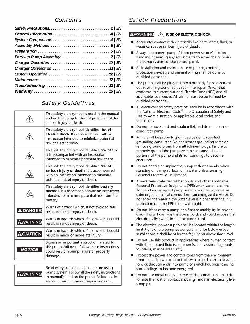
This safety alert symbol is used in the manual and on the pump to alert of potential risk for serious injury or death.This safety alert symbol identifies risk of electric shock. It is accompanied with an instruction intended to minimize potential risk of electric shock.This safety alert symbol identifies risk of fire. It is accompanied with an instruction intended to minimize potential risk of fire.This safety alert symbol identifies risk of serious injury or death. It is accompanied with an instruction intended to minimize potential risk of injury or death. This safety alert symbol identifies battery hazards. It is accompanied with an instruction intended to minimize potential risk from the battery. Warns of hazards which, if not avoided, will result in serious injury or death.Warns of hazards which, if not avoided, could result in serious injury or death.Warns of hazards which, if not avoided, could result in minor or moderate injury.Signals an important instruction related to the pump. Failure to follow these instructions could result in pump failure or property damage.
Read every supplied manual before using pump system. Follow all the safety instructions in manual(s) and on the pump. Failure to do so could result in serious injury or death.
RISK OF ELECTRIC SHOCK
2 | EN Copyright © Liberty Pumps, Inc. 2021 All rights reserved. 2441000A

Use PVC cement in a well-ventilated area away from fire or flames. Follow the PVC cement and primer manufacturer’s instructions.
Do not use an extension cord to power the product. Extension cords can overload both the product and extension cord supply wires. Overloaded wires will get very hot and can catch on fire.
This product requires a separate, properly fused and grounded branch circuit, sized for the voltage and amperage requirements of the pump, as noted on the nameplate. Overloaded branch circuit wires will get very hot and can catch on fire. When used, electrical outlets shall be simplex of the appropriate rating.
Do not use this product with or near flammable or explosive fluids such as gasoline, fuel oil, kerosene, etc. If rotating elements inside pump strike any foreign object, sparks may occur. Sparks could ignite flammable liquids.
These pumps are not to be installed in locations classified as hazardous in accordance with the National Electric Code®, ANSI/NFPA 70.
Do not use to pump flammable or explosive fluids such as gasoline, fuel oil, kerosene, etc. Do not use in flammable and/or explosive atmosphere. Sparks could ignite flammable liquids.
Do not modify the pump/pump system in any way. Modifications may affect seals, change the electrical loading of the pump, or damage the pump and its components.
All pump/pump system installations shall be in compliance with all applicable Federal, State, and Local codes and ordinances.
Do not allow children to play with the pump system.
Do not allow any person who is unqualified to have contact with this pump system. Any person who is unaware of the dangers of this pump system, or has not read this manual, can easily be injured by the pump system.
Wear adequate Personal Protective Equipment when working on pumps or piping that have been exposed to wastewater. Sump and sewage pumps often handle materials that can transmit illness or disease upon contact with skin and other tissues.
Do not remove any tags or labels from the pump or its cord.
Keep clear of suction and discharge openings. To prevent injury, never insert fingers into pump while it is connected to a power source.
Do not use this product with flammable, explosive, or corrosive fluids. Do not use in a flammable and/or explosive atmosphere as serious injury or death could result.
This product contains chemicals known to the State of California to cause cancer and birth defects or other reproductive harm. www.p65warnings.ca.gov.
Battery voltage can cause serious or fatal electrical shock. Follow the battery manufacturer’s recommendations for maintenance and safe use of battery before using charger.
Battery acid is corrosive. Wear adequate Personal Protective Equipment when working with the battery.
Never allow the battery DC terminals to touch each other. This can cause severe burns and start a fire. For added safety, protect the battery in provided battery box.
Only use 12 Volt lead acid batteries with this backup system. Use of batteries with higher or lower output voltages can damage the backup system, leak acid or explode.
Explosive gases develop during normal battery operation. Keep battery in a well ventilated area, away from sparks and open flames (such as pilot light). Never smoke in vicinity of battery. Batteries generate flammable gases both charging and discharging, which can explode or catch fire if ignited.
A check valve is required in the primary sump pump discharge pipe to prevent water from recirculating back into the pit.
Pump clear water only with this pump. Do not dispose of materials such as paint thinner or other
chemicals down drains. Doing so could chemically attack and damage pump system components and cause product malfunction or failure.
Do not use pumps with fluid over 104°F (40°C). Operating the pump in fluid above this temperature can overheat the pump, resulting in pump failure.
Do not use pump system with mud, sand, cement, hydrocarbons, grease, or chemicals. Pump and system components can be damaged from these items causing product malfunction or failure. Additionally, flooding can occur if these items jam the impeller or piping.
Do not run dry. Be prepared for water to leak from the coupling or piping
when disassembling or cutting the discharge pipe. Protect system components, tools, and supplies from getting wet. Dry any work areas that get wet immediately.
Do not position the pump float directly under the inlet from drain tile or in the direct path of any incoming water.
Do not expose pump or discharge to freezing temperatures. Maximum vertical pumping distance is 18 feet (5.5 m). If a Carbon Monoxide (CO) sensor is installed, it must be at
least 15 feet away from the battery charger in order to avoid nuisance CO alarms. Refer to the CO detector’s installation guidelines for more information.
Locate charger as far away from battery as DC cables permit. Never place charger directly above battery being charged as
gases from battery will corrode and damage charger. Never allow battery acid to drip on charger when reading
gravity or filling battery. A Group 27 battery will provide the same performance as a
Group 31 battery, but for a shorter length of time.
RISK OF FIRE
RISK OF SERIOUS INJURY OR DEATH
BATTERY HAZARDS
2441000A Copyright © Liberty Pumps, Inc. 2021 All rights reserved. 3 | EN
Do not expose charger to rain, snow, or liquids. Use charger only for charging a 12 V Lead Acid Battery. It is
not intended to supply power to a low voltage electrical system as the battery may burst and cause injury and property damage.
12V marine-type deep cycle battery recommended (Group 27 or Group 31 AGM or Wet Cell compatible).
Do not operate charger if it has received a sharp blow, been dropped, or otherwise damaged in any way; take it to a qualified service professional.
Never charge a frozen battery. Never charge lithium ion batteries with charger. To protect battery box from chipping and gouging, do not let
the battery box sit on a concrete floor. Install the battery box on a shelf or a protective pad (plywood, 2x4s, etc.).
Always install the battery box in a dry location that is protected from flooding.
Use of a standard automobile battery with this charger is not recommended as an automobile battery may require charging after only 1–2 hours of continuous use and the repeated charging cycles may cause early plate failure in the battery.
General Information
The Model 441-10A battery back-up sump pump system is not a substitute for a primary sump pump. It is designed to temporarily provide backup to a primary sump pump during a power outage or other problem that prevents normal operation of the primary pump.Install this system during a time when the primary pump will not be needed. If this is not possible and water will enter the sump pit during the installation process, an additional pump may be required to keep the pit dry.The Model 441-10A back-up pump will activate when the sump water triggers the back-up pump’s float switch. The system will continue to operate automatically until the issue with the primary pump is corrected, and for as long as the charge in the battery installed with the system lasts.
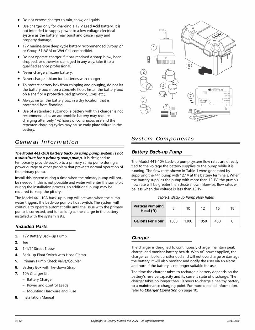
Included Parts
1. 12V Battery Back-up Pump2. Tee3. 1-1/2” Street Elbow4. Back-up Float Switch with Hose Clamp5. Primary Pump Check Valve/Coupler6. Battery Box with Tie-down Strap7. 10A Charger Kit
– Battery Charger– Power and Control Leads– Mounting Hardware and Fuse
8. Installation Manual
System Components
Battery Back-up Pump
The Model 441-10A back-up pump system flow rates are directly tied to the voltage the battery supplies to the pump while it is running. The flow rates shown in Table 1 were generated by supplying the 441 pump with 12.1V at the battery terminals. When the battery supplies the pump with more than 12.1V, the pump’s flow rate will be greater than those shown; likewise, flow rates will be less when the voltage is less than 12.1V.
Charger
The charger is designed to continuously charge, maintain peak charge, and monitor battery health. With AC power applied, the charger can be left unattended and will not overcharge or damage the battery. It will also monitor and notify the user via an alarm and horn if the battery is no longer suitable for use.The time the charger takes to recharge a battery depends on the battery’s reserve capacity and its current state of discharge. The charger takes no longer than 19 hours to charge a healthy battery to a maintenance charging point. For more detailed information, refer to Charger Operation on page 10.
Table 1. Back-up Pump Flow Rates
Vertical Pumping Head (ft) 8 10 12 16 18
Gallons Per Hour 1500 1300 1050 450 0
2
1
4
53
7
6
10 ampCHARGER
Silence
Alarm Reset
Libertypumps.com | Bergen, NY 2031000
Battery Backup System AC Power
Battery Full
Charging
Low Battery
Pump Run
Alarm Silenced
Alarm
4 | EN Copyright © Liberty Pumps, Inc. 2021 All rights reserved. 2441000A
Battery
The total time the battery back-up can operate in standby while the AC power is off greatly depends on the battery installed with the system. Liberty Pumps recommends using a Liberty Pumps StormCell® Group 27 or Group 31 Deep Cycle AGM or Wet Cell lead acid battery with the 441 system. StormCell batteries have been specifically designed to maximize reserve capacity time (the time the battery can operate continuously before it needs to be recharged). Additionally, StormCell batteries have been modified to provide the highest resistance to battery plate degradation due to repeated charging and continuous maintenance charging. With a charged Group 27 or Group 31 deep cycle battery, this back-up system can expect to operate for 4.25 hours continuously or up to 6 days cycling on 4 times an hour, moving 10 gallons of water at 10 feet of vertical head.Note: In an emergency when the system’s deep cycle battery has been depleted, any 12V automobile battery, or other lead acid battery, may be used to keep the back-up pump operational. Be sure to replace the deep cycle battery back into the system as soon as possible. Automobile batteries have much lower reserve capacities and require frequent, repeated charging that will result in early battery failure.
Assembly Methods
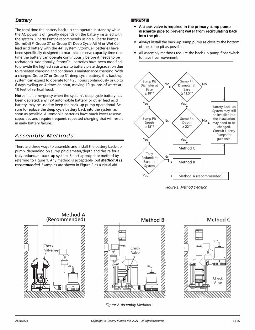
There are three ways to assemble and install the battery back-up pump, depending on sump pit diameter/depth and desire for a truly redundant back-up system. Select appropriate method by referring to Figure 1. Any method is acceptable, but Method A is recommended. Examples are shown in Figure 2 as a visual aid.
A check valve is required in the primary sump pump discharge pipe to prevent water from recirculating back into the pit.
Always install the back-up sump pump as close to the bottom of the sump pit as possible.
All assembly methods require the back-up pump float switch to have free movement.
Figure 1. Method Decision
Figure 2. Assembly Methods
Sump Pit Diameter at
Base?
Sump Pit Diameter at
Base?
Sump Pit Depth
?
Sump Pit Depth
?
Method A (recommended)
Method C
Method B
Battery Back-up System may still be installed but the installation may need to be
changed. Consult Liberty
Pumps for guidance.
Truly Redundant
Back-up System
Yes
No No
NoNo
Yes
Yes
No
Yes
Yes
Check Valve
Method C
Check Valve
Method B
Check Valve
Method A (Recommended)
2441000A Copyright © Liberty Pumps, Inc. 2021 All rights reserved. 5 | EN

Basic Tools and Materials Needed
Methods A, B & C • Additional pump to keep well dry (as needed)• Group 27 or 31 Deep Cycle Wet Cell or AGM lead acid
battery (Liberty Pumps StormCell® Battery recommended)• Channel locks or pliers• Tape measure• 5/16” socket wrench or nut driver• Hacksaw or other pipe cutter• Pencil/marker• PVC cement (solvent weld) and primer• Thread seal tape• Cloth towel
Additional Tools and Material for Method A • Additional PVC pipe for separate discharge line
Additional Tools and Material for Method B • Additional PVC pipe for connecting back-up pump
between elbows• Rubber coupling with clamps to fit the discharge pipe
diameter• 1-1/2” 90° socket x socket elbow
Additional Tools and Material for Method C • Rubber coupling with clamps to fit the discharge pipe
diameter
Preparation
Do not lift or carry a pump or a float assembly by its power cord. This will damage the power cord, and could expose the electrically live wires inside the power cord.
Do not use metal or any other electrical conducting material to raise the float or contact anything inside an electrically live sump pit.
Do not turn the pumps ON until all the fittings are connected with PVC cement and the cement has dried. Loose fittings can unexpectedly disconnect from pipes and cause personal injury and flooding.
To avoid an injury from a collapse of plumbing, support the pipe above the separation before cutting or disassembly. See Figure 3.
Be prepared for water to leak from the coupling or piping when disassembling or cutting the discharge pipe. Protect system components, tools, and supplies from getting wet. Dry any work areas that get wet immediately.
Figure 3. Mark and Cut Pipe
1. Locate the TURN ON water level of the primary sump pump. Mark this location on the discharge pipe. See Figure 3.
2. Drain the sump pit. The water level must be pumped down as low as possible before going on to the next step.To drain the sump pit:a. Raise the float on the float switch until the pump turns on.
Use a wooden broom handle or non-metal stick to do this.ORb. If the sump pump has a piggyback-type power cord,
remove the float switch/power cord plug from the outlet and plug the pump power cord plug directly into the outlet.
3. Confirm sump pit has been drained but do not let the pump run dry as this will damage the pump.Note: A second pump may be required to keep the well dry during installation of the back-up pump.
4. Unplug the primary pump and any other electrical equipment in the sump (i.e., separate alarm).
5. Method A: The primary pump will stay in the pit with the discharge pipe intact unless a check valve needs to be installed. If check valve is already in place, continue to Assembly Method A.To install a check valve, continue to Primary Pump Check Valve Installation.
6. Method B & C: Continue to Primary Pump Check Valve Installation.
RISK OF ELECTRIC SHOCK
Remove rubber coupling(if present)
ORmake 1st cut in this area
Exterior discharge pipe
Support pipe before cutting
Sump pit
TURN ON water level of Primary PumpMark pipe for reference later
Check valve in place
1 2 3
6 | EN Copyright © Liberty Pumps, Inc. 2021 All rights reserved. 2441000A

Primary Pump Check Valve Installation
Always disconnect pump(s) from power source(s) before handling or making any adjustments to either the pump(s), the pump system, or the control panel.
Do not lift or carry a pump or a float assembly by its power cord. This will damage the power cord, and could expose the electrically live wires inside the power cord.
A check valve is required in the primary sump pump discharge pipe to prevent water from recirculating back into the pit.
A primary sump pump check valve is required in the back-up sump pump system. A check valve and rubber coupler are provided for convenience. Verify the presence of a check valve in the primary sump pump. If no check valve is in place, one will need to be installed. Complete the following steps.1. The primary sump pump needs to be separated from the
discharge pipe and removed from pit. Refer to Figure 3.To separate the primary pump from the discharge pipe:a. For applications with rubber couplings, remove the
coupling clamp with a nut driver.b. For applications without rubber couplings, cut the PVC
discharge pipe above the basement floor, at a comfortable level. A new rubber coupling is supplied for reassembly. Note: The discharge pipe will be filled with water. Drain the water from the discharge pipe assembly. Keep the work area dry.
2. Use handle to lift the primary pump and discharge pipe assembly out of the sump.
3. Connect check valve between primary pump discharge and discharge pipe.
4. With primary pump disconnected from the discharge pipe, install the supplied check valve into the primary pump discharge. Thread seal tape is handy but not necessary. Make sure the check valve is installed in the correct direction with the arrow pointing up.
5. Install the supplied coupler. The coupler to be installed with the removable insert UP to allow for easy removal of the primary pump in the future.
6. Continue to Back-up Pump Assembly.
Back-up Pump Assembly
Use PVC cement in a well-ventilated area away from fire or flames. Follow the PVC cement and primer manufacturer’s instructions.
Float Height Adjustment
1. The float in its off position should be mounted in the sump such that it is a minimum of 1/2” above the water level at which the primary pump turns on (as noted in Figure 3).The float can be mounted on any of the vertical pipes in the pit (primary discharge, backup discharge, or other plumbing) provided the float height differential can be maintained and the float is allowed space to travel unobstructed along the float rod.
2. Lightly secure (for now) the float and bracket with the supplied band clamp. Do not fully tighten the clamp at this time as adjustments may be needed later.
Assembly Method A
Liberty Pumps recommends Method A for the most fail-safe back-up pump system. The back-up pump is plumbed with a separate discharge line. The minimum required sump basin diameter is 18” at the bottom of the pit, and the minimum recommended depth of the sump basin is 18”.
Figure 4. Installation Method A
1. Ensure primary pump check valve is installed per Primary Pump Check Valve Installation. If primary pump does not have a check valve, return to Primary Pump Check Valve Installation to install one now. Make sure the check valve is installed in the correct direction.
2. Connect the elbow onto the discharge of the back-up pump. Tighten the clamp to hold secure.
3. Connect a length of pipe into the top of the elbow of the back-up pump discharge.
4. Refer to Float Height Adjustment to mount the back-up pump float switch assembly.
5. Continue to Final Assembly (Method A) on page 9.
RISK OF ELECTRIC SHOCK
RISK OF FIRE
23
4
Discharge pipe(may vary)
1-1/2” Elbow
Method A Back-up Pump Installation• Not to scale • Wiring omitted for clarityMethod A Back-up Pump Installation• Not to scale • Wiring omitted for clarity
2441000A Copyright © Liberty Pumps, Inc. 2021 All rights reserved. 7 | EN
Assembly Method B
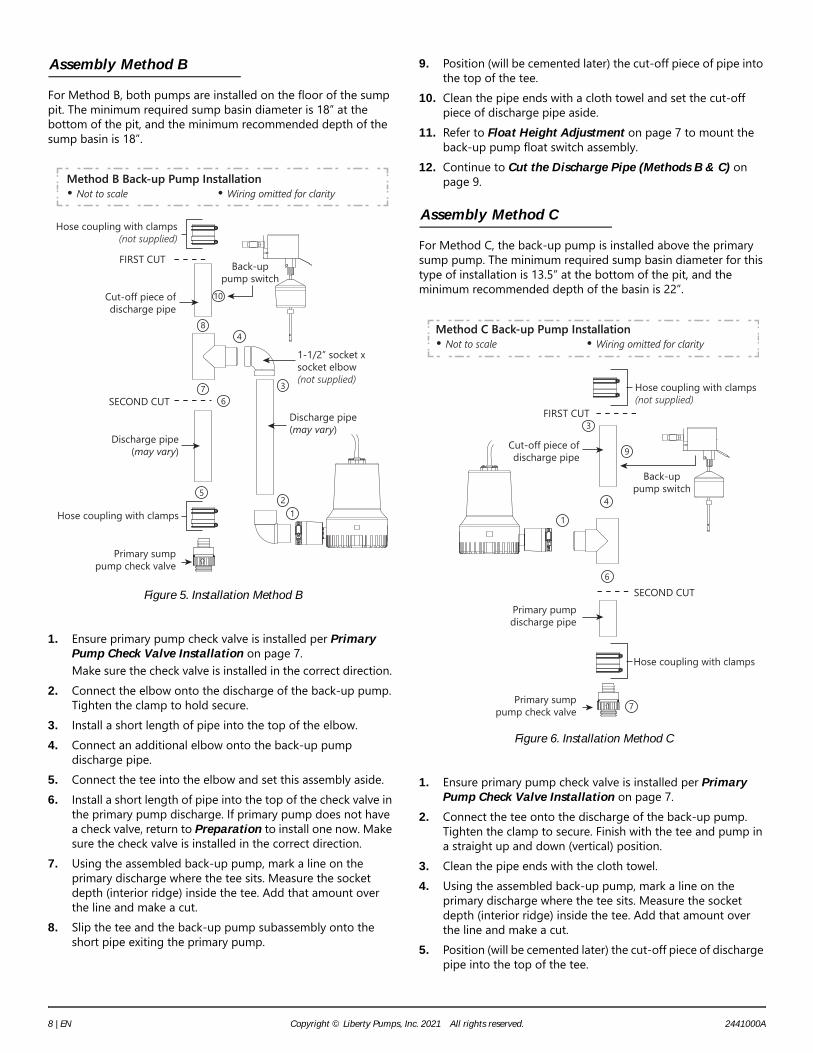
For Method B, both pumps are installed on the floor of the sump pit. The minimum required sump basin diameter is 18” at the bottom of the pit, and the minimum recommended depth of the sump basin is 18”.
Figure 5. Installation Method B
1. Ensure primary pump check valve is installed per Primary Pump Check Valve Installation on page 7.Make sure the check valve is installed in the correct direction.
2. Connect the elbow onto the discharge of the back-up pump. Tighten the clamp to hold secure.
3. Install a short length of pipe into the top of the elbow.4. Connect an additional elbow onto the back-up pump
discharge pipe.5. Connect the tee into the elbow and set this assembly aside.6. Install a short length of pipe into the top of the check valve in
the primary pump discharge. If primary pump does not have a check valve, return to Preparation to install one now. Make sure the check valve is installed in the correct direction.
7. Using the assembled back-up pump, mark a line on the primary discharge where the tee sits. Measure the socket depth (interior ridge) inside the tee. Add that amount over the line and make a cut.
8. Slip the tee and the back-up pump subassembly onto the short pipe exiting the primary pump.
9. Position (will be cemented later) the cut-off piece of pipe into the top of the tee.
10. Clean the pipe ends with a cloth towel and set the cut-off piece of discharge pipe aside.
11. Refer to Float Height Adjustment on page 7 to mount the back-up pump float switch assembly.
12. Continue to Cut the Discharge Pipe (Methods B & C) on page 9.
Assembly Method C
For Method C, the back-up pump is installed above the primary sump pump. The minimum required sump basin diameter for this type of installation is 13.5” at the bottom of the pit, and the minimum recommended depth of the basin is 22”.
Figure 6. Installation Method C
1. Ensure primary pump check valve is installed per Primary Pump Check Valve Installation on page 7.
2. Connect the tee onto the discharge of the back-up pump. Tighten the clamp to secure. Finish with the tee and pump in a straight up and down (vertical) position.
3. Clean the pipe ends with the cloth towel.4. Using the assembled back-up pump, mark a line on the
primary discharge where the tee sits. Measure the socket depth (interior ridge) inside the tee. Add that amount over the line and make a cut.
5. Position (will be cemented later) the cut-off piece of discharge pipe into the top of the tee.
Cut-off piece of discharge pipe
1-1/2” socket x socket elbow(not supplied)
Hose coupling with clamps
Hose coupling with clamps(not supplied)
Back-up pump switch
Discharge pipe(may vary)
Discharge pipe(may vary)
FIRST CUT
SECOND CUT
Primary sump pump check valve
Method B Back-up Pump Installation• Not to scale • Wiring omitted for clarityMethod B Back-up Pump Installation• Not to scale • Wiring omitted for clarity
67
12
3
48
5
10
Cut-off piece of discharge pipe
SECOND CUT
Hose coupling with clamps(not supplied)
Hose coupling with clamps
Primary pump discharge pipe
Primary sump pump check valve
FIRST CUT
Method C Back-up Pump Installation• Not to scale • Wiring omitted for clarityMethod C Back-up Pump Installation• Not to scale • Wiring omitted for clarity
Back-up pump switch
7
6
4
1
3
9
8 | EN Copyright © Liberty Pumps, Inc. 2021 All rights reserved. 2441000A

6. Clean the pipe ends with a cloth towel and set the cut-off piece of discharge pipe aside.
7. Slip the tee and the back-up pump assembly onto the short pipe exiting the primary pump.
8. If primary pump does not have a check valve, return to Preparation to install one now in the primary sump pump discharge pipe between the tee and the pump. Make sure the check valve is installed in the correct direction.
9. Position (will be cemented later) the assembly onto the primary discharge pipe.
10. Refer to Float Height Adjustment on page 7 to mount the back-up pump float switch assembly.
11. Continue to Cut the Discharge Pipe (Methods B & C).
Cut the Discharge Pipe (Methods B & C)
Be prepared for water to leak from the coupling or piping when disassembling or cutting the discharge pipe. Protect system components, tools, and supplies from getting wet. Dry any work areas that get wet immediately.
1. Put the newly assembled dual pump back-up system into the sump pit.The discharge pipe now overlaps the discharge pipe that leads outside.
2. Mark the discharge pipe where it should be cut.Be sure to leave a 1/4” air gap between the ends of the pipes. This gap will absorb the noise from vibration and allow for flexibility.
3. Make the third cut as shown in Figure 7.
Figure 7. Remove Excess Discharge Pipe
Trial Assembly (Methods B & C)
1. Connect the pump discharge pipe to the exterior discharge pipe with a rubber coupling and clamps.Do not tighten the clamps until all the final adjustments are complete.
2. Make the final adjustments. Make sure the pumps and the switches do not interfere with each other. Make sure there is plenty of room for the float switches (primary and back-up) to either swing or to move up and down from their “off” to their “on” positions.
Preliminary Assembly (Methods B & C)
1. Mark the pipe and fittings at all connections with a pencil.These marks will be used as a reassembly guide when joining with primer and cement to be sure everything is still in the right place and nothing has moved.
2. Loosen the rubber coupling and clamp connection.3. Carefully pull the dual pump back-up system out of the pit.4. Take the tee assembly off the primary discharge pipe.
Do not unscrew any of the thread seal taped fittings.5. Prepare all unconnected PVC pipe ends with primer.6. Apply cement to these PVC fittings where indicated by the
marks.
Final Assembly (Method A)
1. Position the back-up pump into the pit.2. Complete the back-up pump separate discharge line.3. Double check back-up pump float height and adjust as
necessary. Refer to Float Height Adjustment on page 7.4. Tighten the float mounting clamp and secure all wires directly
up and out of pit.
Final Assembly (Methods B & C)
1. Position the dual pump back-up system back into the pit.2. Install and tighten the rubber coupling and clamps.3. Double check back-up pump float height and adjust as
necessary. Refer to Float Height Adjustment on page 7.4. Tighten the float mounting clamp, and secure all wires
directly up and out of pit.
Final Assembly Check (Methods A, B & C)
Perform a final assembly check with water to make certain that the float sequence is correct, the float height is correct, and that there are no unforeseen obstructions.
leave 1/4” air gap
leave 1/4” air gap
THIRD CUT
Hose coupling with clamps
Back-up Pump OFF Level
Method B
Check valve in place
Method C
Check valve in place
2441000A Copyright © Liberty Pumps, Inc. 2021 All rights reserved. 9 | EN
Charger Operation
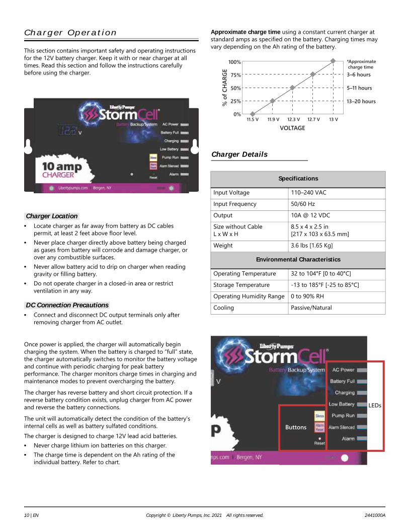
This section contains important safety and operating instructions for the 12V battery charger. Keep it with or near charger at all times. Read this section and follow the instructions carefully before using the charger.
Charger Location • Locate charger as far away from battery as DC cables
permit, at least 2 feet above floor level.• Never place charger directly above battery being charged
as gases from battery will corrode and damage charger, or over any combustible surfaces.
• Never allow battery acid to drip on charger when reading gravity or filling battery.
• Do not operate charger in a closed-in area or restrict ventilation in any way.
DC Connection Precautions • Connect and disconnect DC output terminals only after
removing charger from AC outlet.
Once power is applied, the charger will automatically begin charging the system. When the battery is charged to “full” state, the charger automatically switches to monitor the battery voltage and continue with periodic charging for peak battery performance. The charger monitors charge times in charging and maintenance modes to prevent overcharging the battery.The charger has reverse battery and short circuit protection. If a reverse battery condition exists, unplug charger from AC power and reverse the battery connections.The unit will automatically detect the condition of the battery’s internal cells as well as battery sulfated conditions.The charger is designed to charge 12V lead acid batteries.• Never charge lithium ion batteries on this charger.• The charge time is dependent on the Ah rating of the
individual battery. Refer to chart.
Approximate charge time using a constant current charger at standard amps as specified on the battery. Charging times may vary depending on the Ah rating of the battery.
Charger Details
Specifications
Input Voltage 110–240 VACInput Frequency 50/60 HzOutput 10A @ 12 VDCSize without CableL x W x H
8.5 x 4 x 2.5 in[217 x 103 x 63.5 mm]
Weight 3.6 lbs [1.65 Kg]
Environmental Characteristics
Operating Temperature 32 to 104°F [0 to 40°C]Storage Temperature -13 to 185°F [-25 to 85°C]Operating Humidity Range 0 to 90% RHCooling Passive/Natural
100%
75%
50%
25%
0%
VOLTAGE
% o
f CH
ARGE
*Approximate charge time3–6 hours
5–11 hours
13–20 hours
11.5 V 11.9 V 12.3 V 12.7 V 13 V
LEDs
Buttons
10 | EN Copyright © Liberty Pumps, Inc. 2021 All rights reserved. 2441000A

Charger LEDs
Charger Buttons
Charger Connection
Do not allow any person who is unqualified to have contact with this pump system. Any person who is unaware of the dangers of this pump system, or has not read this manual, can easily be injured by the pump system.
Never allow the battery DC terminals to touch each other. This can cause severe burns and start a fire. For added safety, protect the battery in provided battery box.
Charger and Battery Connection
1. Securely install charger unit in clean, dry location on wall or other fixture separate from battery.
2. Connect charger cord (blue/red) to the pump.
Label LED Indications
AC Power Green AC power is applied.
Battery Full Green Battery is fully charged and operational.
Charging Yellow Battery charging is in process.
Low Battery RedIndicates low battery charge, may be steady or flashing, for specific information, see Charger Conditions and LEDs on page 14.
Pump Run BlueIndicates pump running status, may be steady or flashing, for specific information, see Charger Conditions and LEDs on page 14.
Alarm Silenced Yellow
Indicates an alarm condition is present and the audible alarm (horn) has been silenced.
Alarm RedAlarm condition has occurred, see Charger Conditions and LEDs on page 14 for specifics.
Button Function
Silence
This button is underneath the Silence label on the charger. Firmly pressing this button will silence the current alarm condition. This silence feature is only active for 24 hours. If the condition causing the alarm has not been addressed in this period of time, the horn will resume.Note: there are different categories of Alarms and pressing the Silence once will not completely disable the audible alarm for 24 hours. For example, when the alarm silenced for a pump run, it will still activate if a low battery condition arises, and these conditions if silenced will be superseded by a bad battery condition.
Alarm Reset
This button is underneath the Alarm Reset label on the charger. Firmly pressing this button will remove the alarm conditions instantaneously, and it will not change the state that the charger is in, charging or maintenance mode. It is possible for the reset to be depressed and there to still exist the conditions for an alarm, low voltage, pump running, etc.
Reset
This button is inside the charger. It can be accessed via a small hole below the Alarm Reset button. Insert a non-conductive item (toothpick, insulated screwdriver, etc.) through the hole and press the button for 1 second. This will reboot the charger firmware as if it was just installed. This can also be performed without pressing the button, by disconnecting the power from the charger (both the wall power and the battery) allowing a minute for the charger to dissipate any stored energy, and then reconnecting the power sources. Follow the power connection instructions outlined in Charger and Battery Connection.
RISK OF SERIOUS INJURY OR DEATH
BATTERY HAZARDS
Button Function
FUSE
Negative
Pump Connection
Positive
Positive
Battery Connection
Negative
Float Switch Connection 3
5
2
7
2441000A Copyright © Liberty Pumps, Inc. 2021 All rights reserved. 11 | EN

3. Connect charger cord (red/yellow) to the float switch.4. Install the battery into the battery box.5. Lastly, connect charger cords to the battery posts.
IMPORTANT: Do not face battery when making final connection.Observe the correct polarity of the battery. The WHITE/YELLOW cord (larger ring end) is the POSITIVE terminal; the BLUE/BLACK cord is the NEGATIVE terminal.Observe the display of the battery voltage. Display turns off in one minute to preserve battery life.
6. Tighten battery terminal connections securely.7. Install 20 Amp fuse (provided) in yellow wiring.8. Plug the charger into a 115/120 VAC electric outlet. The
charger should be powered from a separate circuit with minimum 10A service. IMPORTANT: Do not use a switch-controlled outlet.
9. Mark circuit in main power panel “Back-up sump pump power supply; do not turn off”.
10. With the charger properly connected and plugged in, the charger displays the power and battery status.Observe AC Power and Charging or Battery Full LEDs. In case the battery is too discharged, the Low Battery and Alarm LEDs may be lit. The horn may also sound.Note: An audible alarm automatically sounds when the system runs if the alarm is enabled. The alarm is silenced for 24 hours when the Silence button is pressed. See Charger Buttons | Silence on page 11 for conditions and exceptions.
11. Secure the battery in the box with the provided hold-down strap to prevent unwanted access to the battery.
12. When disconnecting charger, always do so in reverse sequence of connecting procedure and break first connection while as far away from battery as practical.
Figure 8. Complete Back-up Pump System Example
Test 10A Charger System
Do not use metal or any other electrical conducting material to raise the float or contact anything inside an electrically live sump pit.
1. Battery should be fully charged (green Battery Full LED) before placing system into service.
2. Lift the back-up pump float switch. The pump should start. The following LEDs should be ON: AC Power, Charging, Pump Run and Alarm. Alarm will sound. Observe the pump is running. Release the float switch. Pump should stop.
3. Lift the pump float switch again. Keep the switch engaged, and press the Silence button. Alarm should stop. Release the float to turn the pump off.
4. Press the Alarm Reset button. Alarm, Alarm Silenced, and Pump Run LEDs should go out. Consult the factory if the charger does not function as described according to these steps.
System Operation
Perform a final assembly check with water to make sure that the float sequence is correct and that there are no unforeseen obstructions.
Starting System
1. Verify all plumbing components in the basin are installed correctly and functional; all valves are open and ready for pump use; any PVC cement has fully dried.
2. Double check all wiring connections. Re-tighten all connections.
3. Ensure pump and float switch have no obstructions.4. With all electrical and mechanical connections complete and
secure, turn on power to pump.5. Verify operation of the pump, floats, and charger circuits.6. Run several cycles of water through the system to verify
correct control operation for the installation.Be certain to complete adequate testing to verify all components are working properly.
Maintenance
Accidental contact with electrically live parts, items, fluid, or water can cause serious injury or death.
Always disconnect pump(s) from power source(s) before handling or making any adjustments to either the pump(s), the pump system, or the control panel.
Not to Scale
RISK OF ELECTRIC SHOCK
RISK OF ELECTRIC SHOCK
12 | EN Copyright © Liberty Pumps, Inc. 2021 All rights reserved. 2441000A

Pump Maintenance
Inspect and test the system monthly for proper operation:1. Disconnect all power to each pump unit in the pit.2. Check pump for debris and/or build-up that may interfere
with pump or float switch operation. The float switch must be free to move without any restriction through its complete travel.
3. Reconnect power to back-up pump.4. Allow water level to rise to activate the back-up pump.
Alternately, add water to the sump to the “on” level for the back-up pump.
5. Verify the back-up pump activates and empties water from the basin.
6. Reconnect primary pump to wall outlet.7. Verify the primary pump turns on and lowers the water to the
normal operating level and then turns off.8. Verify GFCI is working properly. Use the test button to
confirm proper ground-fault protection.9. Verify proper operation of system at conclusion of
maintenance.
Charger Maintenance
Inspect the charger monthly for proper operation:1. Disconnect the charger from power while cleaning.2. Clean the case and cords with a dry cloth. Inspect charger
condition.
Battery Maintenance
Follow the battery manufacturer’s recommendations for maintenance and safe use of the battery. Liberty Pumps StormCell batteries are maintenance free.Inspect the battery monthly for proper operation:1. Battery cover and terminals should be kept clean, dry and
free of corrosion. Battery vent caps must be secured to the battery during use and charging period. Remove vent caps only to inspect electrolyte levels or specific gravities.
2. When the battery or its terminals require cleaning, use only biodegradable cleaner-neutralizer solutions that can be safely applied and disposed of through a common sanitary sewer. Other chemical-based solutions are often dangerous, ineffective and cannot be disposed of in an environmentally safe manner.
3. Inspect cable-to-terminal connections to ensure connections are tight and free of corrosion. Battery cables must be intact with no exposed wires.
Troubleshooting
Pump Troubleshooting
Problem Corrective Action
Pump will not run.
Check all wiring connections.
Check for low or defective battery.
Confirm that float switch is free to move up and down.
Verify float switch is working properly.
Check for a blown fuse in the charger wiring.
Pump cycles too frequently.
Improper float switch setting. Adjust distance between rubber stoppers on float rod to achieve desired pump cycle. Refer to Float Height Adjustment on page 7.
Primary check valve located between discharge of primary pump and the back-up sump pump tee is not installed or is not working properly. Check all valves. Install or repair as required.
Motor hums but pump will not run. Check for low or defective battery.
Pump runs but pumps very little or no water.
Confirm a check valve is installed and functioning between the primary pump discharge and the back-up sump pump tee. Check all valves. Install or repair as required.
Check for obstruction in discharge pipe.
Discharge pipe length and/or height exceeds capacity of pump. See Table 1 for pump capacity.
Check for low or defective battery.
Positive (+) and negative (–) battery wires are reversed.
2441000A Copyright © Liberty Pumps, Inc. 2021 All rights reserved. 13 | EN
Charger Troubleshooting
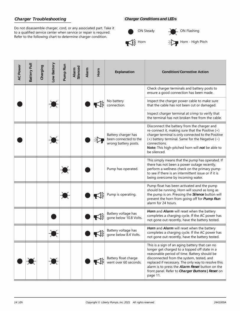
Do not disassemble charger, cord, or any associated part. Take it to a qualified service center when service or repair is required. Refer to the following chart to determine charger condition.
Charger Conditions and LEDs
ON Steady ON Flashing
Horn Horn - High Pitch
AC Po
wer
Batte
ry Fu
ll
Char
ging
Low
Batte
ry
Pum
p Ru
n
Alar
mSil
ence
d
Alar
m
Horn Explanation Condition/Corrective Action
No battery connection.
Check charger terminals and battery posts to ensure a good connection has been made.
Inspect the charger power cable to make sure that the cable has not been cut or damaged.
Inspect charger terminal at crimp to verify that the terminal has not broken free from the cable.
Battery charger has been connected to the wrong battery posts.
Disconnect the battery from the charger and re-connect it, making sure that the Positive (+) charger terminal is only connected to the Positive (+) battery terminal. Same for the Negative (−) connections.Note: This high-pitched horn will not be able to be silenced.
Pump has operated.
This simply means that the pump has operated. If there has not been a power outage recently, perform a wellness check on the primary pump to see if there is an intermittent issue or if it is being overcome by incoming water.
Pump is operating.
Pump float has been activated and the pump should be running. Horn will sound as long as the pump is on. Pressing the Silence button will prevent the horn from going off for Pump Run alarm for 24 hours.
Battery voltage has gone below 10.8 Volts.
Horn and Alarm will reset when the battery completes a charging cycle. If the AC power has not gone out recently, have the battery tested.
Battery voltage has gone below 8.4 Volts.
Horn and Alarm will reset when the battery completes a charging cycle. If the AC power has not gone out recently, have the battery tested.
Battery float charge went over 60 seconds.
This is a sign of an aging battery that can no longer get charged to a topped off state in a reasonable period of time. Battery should be disconnected from the system, tested, and replaced if necessary. The only way to resolve this alarm is to press the Alarm Reset button on the front panel. Refer to Charger Buttons | Reset on page 11.
14 | EN Copyright © Liberty Pumps, Inc. 2021 All rights reserved. 2441000A
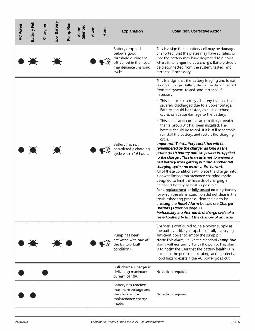
Battery dropped below a good threshold during the off period in the float/maintenance charging cycle.
This is a sign that a battery cell may be damaged or shorted, that the plates may have sulfated, or that the battery may have degraded to a point where it no longer holds a charge. Battery should be disconnected from the system, tested, and replaced if necessary.
Battery has not completed a charging cycle within 19 hours.
This is a sign that the battery is aging and is not taking a charge. Battery should be disconnected from the system, tested, and replaced if necessary.• This can be caused by a battery that has been
severely discharged due to a power outage. Battery should be tested, as such discharge cycles can cause damage to the battery.
• This can also occur if a large battery (greater than a Group 31) has been installed. The battery should be tested. If it is still acceptable, reinstall the battery, and restart the charging cycle.
Important: This battery condition will be remembered by the charger as long as the power (both battery and AC power) is supplied to the charger. This is an attempt to prevent a bad battery from getting put into another full charging cycle and create a fire hazard.All of these conditions will place the charger into a power-limited maintenance charging mode, designed to limit the hazards of charging a damaged battery as best as possible. For a replacement or fully tested existing battery for which the alarm condition did not clear in the troubleshooting process, clear the alarm by pressing the Reset Alarm button, see Charger Buttons | Reset on page 11.Periodically monitor the first charge cycle of a tested battery to limit the chances of an issue.
Pump has been activated with one of the battery fault conditions.
Charger is configured to be a power supply as the battery is likely incapable of fully supplying sufficient power to empty the sump pit.Note: This alarm, unlike the standard Pump Run alarm, will not turn off with the pump. This alarm is to notify the user that the battery health is in question, the pump is operating, and a potential flood hazard exists if the AC power goes out.
Bulk charge. Charger is delivering maximum current of 10A.
No action required.
Battery has reached maximum voltage and the charger is in maintenance charge mode.
No action required.
AC Po
wer
Batte
ry Fu
ll
Char
ging
Low
Batte
ry
Pum
p Ru
n
Alar
mSil
ence
d
Alar
m
Horn Explanation Condition/Corrective Action
2441000A Copyright © Liberty Pumps, Inc. 2021 All rights reserved. 15 | EN

Warranty
Liberty Pumps Wholesale Products Limited Warranty
Liberty Pumps, Inc. warrants that Liberty Pumps wholesale products are free from all factory defects in material and workmanship for a period of three (3) years from the date of purchase (excluding* batteries and “Commercial Series” models). The date of purchase shall be determined by a dated sales receipt noting the model and serial number of the pump. The dated sales receipt must accompany the returned pump if the date of return is more than three years from the date of manufacture noted on the pump nameplate.The manufacturer's sole obligation under this Warranty shall be limited to the repair or replacement of any parts found by the manufacturer to be defective, provided the part or assembly is returned freight prepaid to the manufacturer or its authorized service center, and provided that none of the following warranty-voiding characteristics are evident:The manufacturer shall not be liable under this Warranty if the product has not been properly installed, operated, or maintained per manufacturer instructions; if it has been disassembled, modified, abused, or tampered with; if the electrical cord has been cut, damaged, or spliced; if the pump discharge has been reduced in size; if the pump has been used in water temperatures above the advertised rating; if the pump has been used in water containing sand, lime, cement, gravel, or other abrasives; if the product has been used to pump chemicals, grease, or hydrocarbons; if a non-submersible motor has been subjected to moisture; or if the label bearing the model and serial number has been removed.Liberty Pumps, Inc. shall not be liable for any loss, damage, or expenses resulting from installation or use of its products, or for indirect, incidental, and consequential damages, including costs of removal, reinstallation or transportation.There is no other express warranty. All implied warranties, including those of merchantability and fitness for a particular purpose, are limited to three years from the date of purchase. This Warranty contains the exclusive remedy of the purchaser, and, where permitted, liability for consequential or incidental damages under any and all warranties are excluded.*Liberty Pumps, Inc. warrants StormCell batteries for 1 year from date of purchase, and warrants that pumps of its Commercial Series are free from all factory defects in material and workmanship for a period of 18 months from the date of installation or 24 months from the date of manufacture, whichever occurs first, and provided that such products are used in compliance with their intended applications as set forth in the technical specifications and manuals.
7000 Apple Tree AvenueBergen, NY 14416ph: 1-800-543-2550fax: 1-585-494-1839www.LibertyPumps.com
16 | EN Copyright © Liberty Pumps, Inc. 2021 All rights reserved. 2441000A