Embed Size (px)
Citation preview

Product Data Sheet00813-0100-4799, Rev DAMarch 2003 Model 3244MV
www.rosemount.com
Easy integration to a Profibus DP network
5-year stability reduces maintenance costs
Dual-compartment housing provides the highest reliability in harsh industrial environments
18-bit analog-to-digital converter with ambient temperature compensation enhances performance and process quality
Transmitter-Sensor Matching feature improves measurement accuracy by 75%
ContentThe Ultimate Temperature Transmitter for Control and Safety Applications . . . . . . . . . . . . page 2
Specifications . . . . . . . . . . . . . . . . . . . . . . . . . . . . . . . . . . . . . . . . . . . . . . . . . . . . . . . . . . . page 3
Product Certifications . . . . . . . . . . . . . . . . . . . . . . . . . . . . . . . . . . . . . . . . . . . . . . . . . . . . . page 6
Dimensional Drawings . . . . . . . . . . . . . . . . . . . . . . . . . . . . . . . . . . . . . . . . . . . . . . . . . . . . page 8
Ordering Information . . . . . . . . . . . . . . . . . . . . . . . . . . . . . . . . . . . . . . . . . . . . . . . . . . . . . page 10
Configuration Data Sheet . . . . . . . . . . . . . . . . . . . . . . . . . . . . . . . . . . . . . . . . . . . . . . . . . page 12
Model 3244MV MultiVariable Temperature Transmitter with Profibus-PA
Product Data Sheet00813-0100-4799, Rev DA
March 2003Model 3244MV
2
The Ultimate Temperature Transmitter for Control and Safety Applications
The Model 3244MV MultiVariable Temperature Transmitter with Profibus-PA communications provides superior accuracy, stability, and reliability, making it the industryleading temperature transmitter used in control and safety applications.
The Model 3244MV with Profibus-PA has a dual-sensor input capability that allows the transmitter to accept simultaneous input from two independent sensors. You can use this transmitter for measuring differential temperatures, averaging temperature, or redundant temperature measurement.
BEST IN CLASS RELIABILITYProvides industry-leading five year stability, which reduces maintenance costs. The Transmitter-Sensor Matching feature eliminates interchangeability error, which improves accuracy by 75%.
SUPERIOR HOUSING DESIGNDesigned with dual-compartment housing that provides the highest reliability in harsh environments. The dual-compartment housing provides isolation between the electronics and terminal compartments.
LOCAL INDICATIONThe LCD meter provides local indication of temperature measurement, status, and diagnostics.
OUTPUT PROTOCOL FLEXIBILITYCommunicates digitally using Profibus-PA, which can be integrated to a Profibus DP network.
EXCELLENT AMBIENT TEMPERATURE COMPENSATIONIt is virtually immune to ambient temperature fluctuations, due to individual transmitter characterizations at the factory. It maintains excellent accuracy in dynamic industrial environments.
Rosemount Temperature SolutionsModel 3144P Temperature Transmitter
Field mount style available with HART® protocol.
Model 3244MV Temperature TransmitterField mount style available with FOUNDATION fieldbus and Profibus-PA protocols.
Model 644 Smart Temperature TransmitterHead or rail mount styles available with HART protocol.
Model 848T Eight Input Temperature TransmitterEight input transmitter available with FOUNDATION fieldbus protocol.
Model 248 Temperature AssemblyHead mount DIN form B transmitter available with HART protocol.
Rosemount sensors, thermowells, and extensionsRosemount has a broad offering of RTD and thermocouples that are designed to meet plant requirements.
Product Data Sheet00813-0100-4799, Rev DAMarch 2003
3
Model 3244MV
SpecificationsFUNCTIONALInputsUser-selectable. See Accuracy on page 4(Sensor terminals are rated to 42.4 V dc.)
OutputsManchester-encoded digital signal that conforms to IEC 1158-2 and ISA 50.02
IsolationInput/output isolation tested to 500 V rms (707 V dc)
Power SupplyExternal power supply is required. Transmitter operation is between 9.0 and 32.0 V dc, 17.5 mA maximum. (Transmitter power terminals are rated to 42.4 V dc.)
Profibus-PA .
Temperature Limits
Transient Protection Option (available at a later date)The transient protector helps to prevent damage to the transmitter from transients induced on the loop wiring by lightning, welding, heavy electrical equipment, or switch gears. The transient protection electronics are contained in an add-on assembly that attaches to the standard transmitter terminal block. The transient protector is tested per the following standard:ANSI/IEEE C62.41-1991 (IEEE 587), Location Categories A2, B3.1kV peak (10 1000 S Wave)6kV / 3kA peak (1.2 50 S Wave 8 20 S Combination Wave)6kV / 0.5kA peak (100 kHz Ring Wave)4kV peak EFT (5 50 nS Electrical Fast Transient)Nominal clamping voltages:
77 V (normal mode) 90 V (common mode)
AlarmsThe AI block allows the user to configure the alarm to HI-HI, HI, LO, or LO-LO, with a variety of priority levels and hysteresis
StatusIf self-diagnostics detect a sensor burnout or a transmitter failure, the status of the measurement will be updated accordingly.
Humidity Limits0100% relative humidity.
Turn-on TimePerformance within specifications is achieved less than 10.0 seconds after power is applied to the transmitter.
Update TimeApproximately 0.5 seconds for a single sensor (1.0 second for two sensors).
TABLE 1. Block Information
BlockExecution Time (milliseconds) Slot Number
Physical (PB) 2Transducer (TB) 3, 4, 5,Transducer (TB) 3, 4, 5,Transducer (TB) 3, 4, 5,Analog Input 1 (AI1) 50 6Analog Input 2 (AI2) 50 7Analog Input 3 (AI3) 50 8
Description Operating Limit Storage LimitWithout LCD Meter 40 to 185 °F
40 to 85 °C60 to 250 °F50 to 120 °C
With LCD Meter 4 to 185 °F20 to 85 °C
50 to 185 °F45 to 85 °C
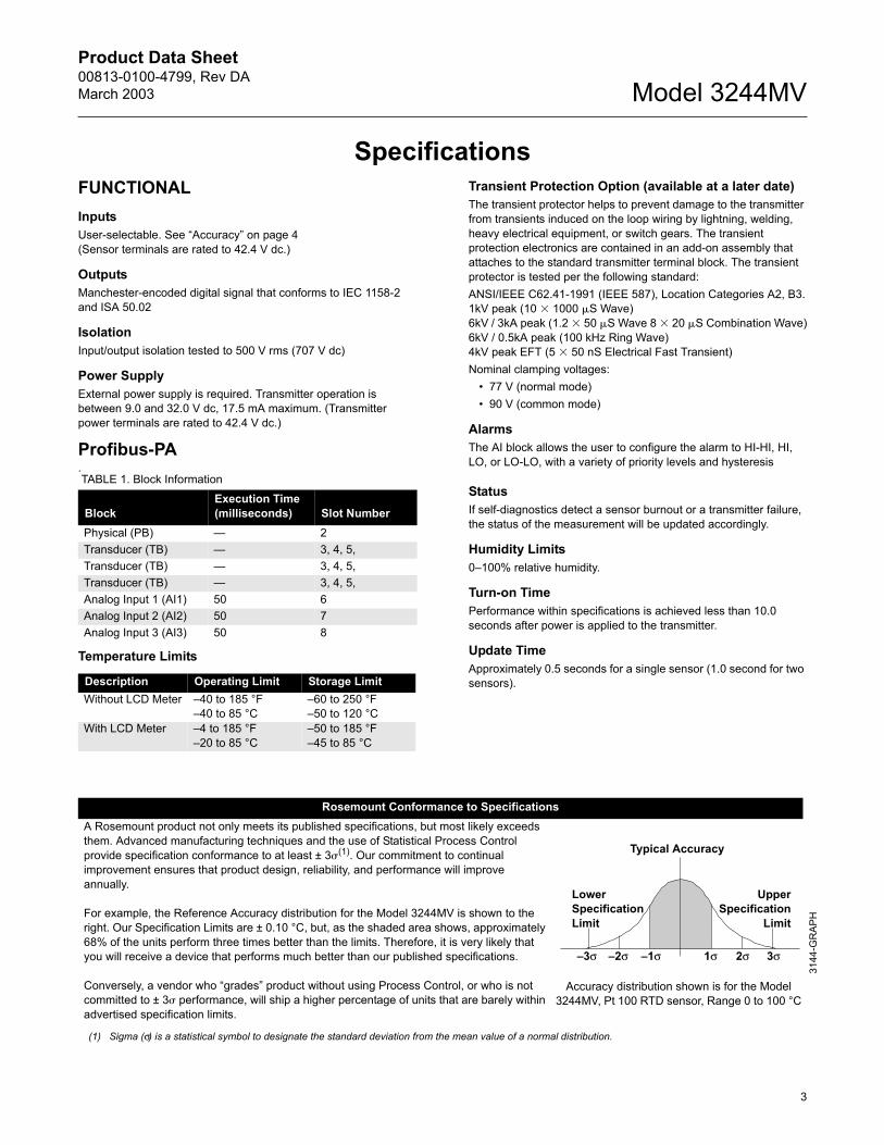
Rosemount Conformance to SpecificationsA Rosemount product not only meets its published specifications, but most likely exceeds them. Advanced manufacturing techniques and the use of Statistical Process Control provide specification conformance to at least ± 3(1). Our commitment to continual improvement ensures that product design, reliability, and performance will improve annually.
For example, the Reference Accuracy distribution for the Model 3244MV is shown to the right. Our Specification Limits are ± 0.10 °C, but, as the shaded area shows, approximately 68% of the units perform three times better than the limits. Therefore, it is very likely that you will receive a device that performs much better than our published specifications.
Conversely, a vendor who grades product without using Process Control, or who is not committed to ± 3 performance, will ship a higher percentage of units that are barely within advertised specification limits.
Accuracy distribution shown is for the Model 3244MV, Pt 100 RTD sensor, Range 0 to 100 °C
(1) Sigma (σ) is a statistical symbol to designate the standard deviation from the mean value of a normal distribution.
Lower Specification Limit
UpperSpecification
Limit
Typical Accuracy
3144
-GR
APH
3σ 2σ 1σ 1σ 2σ 3σ
Product Data Sheet00813-0100-4799, Rev DA
March 2003Model 3244MV
4
PERFORMANCE The Model 3244MV with Profibus-PA maintains a specification conformance of at least 3.
Accuracy
Stability ±0.1% of reading or 0.1 °C, whichever is greater, for 24
months for RTDs. ±0.1% of reading or 0.1 °C, whichever is greater, for 12
months for thermocouples.
5 Year Stability ±0.25% of reading or 0.25 °C, whichever is greater, for 5 years
for RTDs ±0.5% of reading or 0.5 °C, whichever is greater, for 5 years
for thermocouples.
Sensor Lead Wire Resistance EffectRTD InputWhen using a 4-wire RTD, the effect of lead resistance is eliminated and has no impact on accuracy. However, a 3-wire sensor will not fully cancel lead resistance error because it cannot compensate for imbalances in resistance between the lead wires. A 2-wire sensor will produce the largest error because it directly adds the lead wire resistance to the sensor resistance. For 2- and 3-wire RTDs, an additional lead wire resistance error is induced with ambient temperature variations. The Accuracy table and the examples shown below help quantify these errors.
Examples of Approximate Basic Error Calculation:Given:
Total cable length = 150 m Unbalance of the lead wires at 20 °C = 0.5 Ω Resistance/length (18 AWG Cu) = 0.025 Ω/m Temperature Coefficient (Cu) = 0.0039 Ω/Ω/ °C Approximate Pt 100 resistance variation with temperature =
0.39 Ω/ °CPt 100 3-wire RTD:
Lead wire resistance seen by the transmitter = 0.5 Ω Basic error = 0.5 Ω/(0.39 Ω/ °C) = 1.3 °C Error due to an ambient temperature variation of ± 25 °C = ±
0.13 °CPt 100 2-wire RTD:
Lead wire resistance seen by the transmitter = 150 m 2 wires 0.025 Ω/m = 7.5 Ω
Basic error = 7.5 Ω/(0.39 Ω/°C) = 19.2 °C Error due to an ambient temperature variation of ± 25 °C = ±
1.9 °CThermocouple and Millivolt Input
dc input impedance > 10M ohms.
Example of Approximate Error Calculation:
RFI EffectWorst case RFI Effect is equivalent to the transmitters nominal accuracy specification per Accuracy on page 4 when tested in accordance with EN 61000-4-3, 10 V/m, 80 to 1000 MHz, and 30 V/m, 26-500 MHz (Increased NAMUR), with twisted shielded cables (Type A Profibus type).
Sensor Options Input Ranges Accuracy(1)
(1) The transmitters accuracy is valid for the entire input range of the sensor.
2-, 3-, 4-Wire RTDs °C °F °C °FPt 100 ( = 0.00385)(2)
(2) IEC 751; α = 0.00385, 1995.
200 to 850 328 to 1562 ± 0.10 ± 0.18Pt 100 ( = 0.003916)(3)
(3) JIS 1604, 1981.
200 to 645 328 to 1193 ± 0.10 0.18± Pt 200(2) 200 to 850 328 to 1562 ± 0.22 ± 0.40Pt 500(2) 200 to 850 328 to 1562 0.14 ± 0.25Pt 1000(2) 200 to 300 328 to 572 ± 0.08 ± 0.14Ni 120(4)
(4) Edison Curve No. 7.
200 to 300 94 to 572 ± 0.08 ± 0.14Cu 10(5)
(5) Edison Copper Winding No. 15.
200 to 250 58 to 482 ± 1.00 ± 1.80Thermocouples °C °F °C °FNIST Type B(6) (7) (8)
(6) NIST Monograph 175.
(7) Accuracy for NIST Type B T/C is ±3.0 °C (5.4 °F) from 100 to 300 °C (212 to 572°F).
(8) Total accuracy for thermocouple only: sum of accuracy +0.25 °C (cold junction accuracy).
212 to 3308 100 to 1820 ± 0.75 ± 1.35NIST Type E(5) (8) 58 to 1832 50 to 1000 ± 0.20 ± 0.36NIST Type J(6) (8) 292 to 1400 180 to 760 ± 0.25 ± 0.45NIST Type K(6) (8) 292 to 2502 180 to 1372 ± 0.50 ± 0.90NIST Type N(6) (8) 32 to 2372 0 to 1300 ± 0.40 ± 0.72NIST Type R(6) (8) 32 to 3214 0 to 1768 ± 0.60 ± 1.08NIST Type S(6) (8) 32 to 3214 0 to 1768 ± 0.50 ± 0.90NIST Type T(6) (8) 328 to 752 200 to 400 ± 0.25 ± 0.45Millivolt Input(9)
(9) Millivolt inputs are not approved for use with CSA option code I6.
10 to 100 mV ± 0.015 mV2-, 3-, 4-Wire Ohm Input
0 to 2000 Ωs ±0.35 ohm
TABLE 2. RTD Sensor Input Approximate Basic ErrorSensor Input Approximate Basic Error
4-wire RTD None (independent of lead wire resistance)3-wire RTD ± 1.0 Ω in reading per ohm of unbalanced lead
wire resistance(1)
(1) Unbalanced lead wire resistance = maximum imbalance between any two leads.
2-wire RTD 1.0 Ω in reading per ohm of lead wire resistance
Approx. Error Total Sensor Lead Resistance10M ohms
-------------------------------------------------------------------------------- Absolute Value of Reading in mV×=
Product Data Sheet00813-0100-4799, Rev DAMarch 2003
5
Model 3244MV
Ambient Temperature Effect Transmitters may be installed in locations where the ambient temperature is between 40 and 85 °C. Each transmitter is individually characterized over this ambient temperature range at the factory in order to maintain excellent accuracy performance in dynamic industrial environments. This special manufacturing technique is accomplished through extreme hot and cold temperature profiling with individual adjustment factors programmed into each transmitter. Transmitters automatically adjust for component drift caused by changing environmental conditions.
Temperature Effects ExampleWhen using a PT 100 (α = 0.00385) sensor input with a 30 °C ambient temperature, the:
Temp Effects would be: 0.0015 °C x 3930 20) = 0.015 °C. Worst Case Error: Sensor Accuracy + Temperature Effects =
0.10 °C + 0.015 °C = 0.115 °C Total Probably Error
Vibration EffectTransmitters tested to the following specifications with no effect on performance:
FrequencyAcceleration1060 Hz0.21 mm peak displacement602000 Hz3 gs
Self CalibrationThe transmitters analog-to-digital circuitry automatically self-calibrates for each temperature update by comparing the dynamic measurement to extremely stable and accurate internal reference elements.
PHYSICALConduit ConnectionsThe standard field mount housing has ½14 NPT conduit entries. Additional conduit entry type are available, including PG13.5 (PG11), M20 X 1.5 (CM20), or JIS G ½. When an of these additional entry types are ordered, adapters are placed in the standard field housing so these alternative conduit types fit correctly. See Dimensional Drawings for increased dimensions.
Materials of ConstructionElectronics housing
Low-copper aluminum or CF-8M (cast version of 316 Stainless Steel).
Paint Polyurethane.
Cover o-rings Buna-N.
MountingTransmitters may be attached directly to the sensor. Optional mounting brackets permit remote Mounting (see Figure 2-5 and Figure 2-6 on page 2-7).
WeightAluminum:2.5 lb (1.1 kg).Stainless Steel:7.2 lb (3.3 kg).Add 1.0 lb (0.5 kg) for bracket options.
Enclosure RatingsNEMA 4X and CSA Enclosure Type 4X, IP66, IP68.
Sensor OptionsAccuracy per 1.0 °C (1.8 °F) Change in Ambient(1)
(1) Change in ambient is in reference to the calibration temperature of the transmitter (20 °C (68 °F) typical from factory).
2-, 3-, 4-Wire RTDsPt 100 ( = 0.00385) 0.0015 °CPt 100 ( = 0.003916) 0.0015 °CPt 500 0.0023 °CPt 200 0.0015 °CPt 1000 0.0015°CNi 120 0.0010 °CCu 10 0.015 °CThermocouplesNIST Type B 0.014 °C if reading ≥ 1000 °C
0.029 °C 0.0021% of (reading300) if 300 °C ≤ reading < 1000 °C0.046 °C 0.0086% of (reading100) if 100 °C ≤ reading < 300 °C
NIST Type E 0.004 °C + 0.00043% of readingNIST Type J 0.004 °C + 0.00029% of reading if reading ≥ 0 °C
0.004 °C + 0.0020% of abs. val. reading if reading < 0 °C
NIST Type K 0.005 °C + 0.00054% of reading if reading ≥ 0 °C0.005 °C + 0.0020% of abs. val. reading if reading < 0 °C
NIST Type N 0.005 °C + 0.00036% of readingNIST Type R 0.015 °C if reading ≥ 200 °C
0.021 °C 0.0032% of reading if reading < 200 °C
NIST Type S 0.015 °C if reading ≥ 200 °C0.021 °C 0.0032% of reading if reading < 200 °C
NIST Type T 0.005 °C if reading ≥ 0 °C0.005 °C + 0.0036% of abs. val. reading if reading < 0 °C
Millivolt Input 0.00025 mV2-, 3-, 4-Wire Ohm 0.007
0.102 0.0152+ 0.101° C=( )=
Product Data Sheet00813-0100-4799, Rev DA
March 2003Model 3244MV
6
Product Certifications
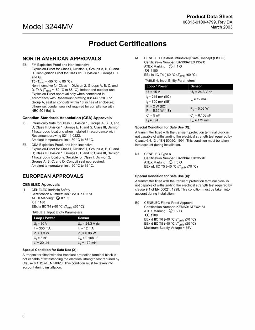
NORTH AMERICAN APPROVALSE5 FM Explosion-Proof and Non-incendive:
Explosion-Proof for Class I, Division 1, Groups A, B, C, and D. Dust Ignition Proof for Class II/III, Division 1, Groups E, F and G. T5 (Tamb = -50 °C to 85 °C). Non-incendive for Class 1, Division 2, Groups A, B, C, and D. T4A (Tamb = -50 °C to 85 °C). Indoor and outdoor use. Explosion-Proof approval only when connected in accordance with Rosemount drawing 03144-0220. For Group A, seal all conduits within 18 inches of enclosure; otherwise, conduit seal not required for compliance with NEC 501-5a(1).
Canadian Standards Association (CSA) ApprovalsI6 Intrinsically Safe for Class I, Division 1, Groups A, B, C, and
D; Class II, Division 1, Groups E, F, and G; Class III, Division 1 hazardous locations when installed in accordance with Rosemount drawing 03144-0222. Ambient temperature limit -50 °C to 85 °C.
E6 CSA Explosion-Proof, and Non-incendive.Explosion-Proof for Class I, Division 1, Groups A, B, C, and D; Class II, Division 1, Groups E, F, and G; Class III, Division 1 hazardous locations. Suitable for Class I, Division 2, Groups A, B, C, and D. Conduit seal not required. Ambient temperature limit -50 °C to 85 °C.
EUROPEAN APPROVALSCENELEC ApprovalsI1 CENELEC Intrinsic Safety
Certification Number: BAS98ATEX1357XATEX Marking: II 1 G
1180EEx ia IIC T4 (-60 °C ≤ Tamb ≤ 60 °C)
Special Condition for Safe Use (X):A transmitter fitted with the transient protection terminal block is not capable of withstanding the electrical strength test required by Clause 6.4.12 of EN 50020. This condition must be taken into account during installation.
IA CENELEC Fieldbus Intrinsically Safe Concept (FISCO)Certification Number: BAS98ATEX1357XATEX Marking: II 1 G
1180EEx ia IIC T4 (-60 °C ≤ Tamb ≤ 60 °C)
Special Condition for Safe Use (X):A transmitter fitted with the transient protection terminal block is not capable of withstanding the electrical strength test required by Clause 6.4.12 of EN 50020: 1994. This condition must be taken into account during installation.
N1 CENELEC Type n Certification Number: BAS98ATEX3358XATEX Marking: II 3 GEEx nL IIC T5 (-40 °C ≤ Tamb ≤ 70 °C)
Special Condition for Safe Use (X):A transmitter fitted with the transient protection terminal block is not capable of withstanding the electrical strength test required by clause 9.1 of EN 50021: 1998. This condition must be taken into account during installation.
E9 CENELEC Flame-Proof ApprovalCertification Number: KEMA01ATEX2181ATEX Marking: II 2 G
1180EEx d IIC T6 (-40 °C ≤ Tamb ≤ 70 °C)EEx d IIC T5 (-40 °C ≤ Tamb ≤ 80 °C)Maximum Supply Voltage = 55V
TABLE 3. Input Entity ParametersLoop / Power SensorUi = 30 V Uo = 24.3 V dcIi = 300 mA Io = 12 mA Pi = 1.3 W Po = 0.06 WCi = 5 nF Co = 0.108 µFLi = 20 µH Lo = 179 mH
TABLE 4. Input Entity ParametersLoop / Power SensorUi = 15 V Uo = 24.3 V dcIi = 215 mA (IIC)Ii = 500 mA (IIB)
Io = 12 mA
Pi = 2 W (IIC)Pi = 5.32 W (IIB) Po = 0.06 W
Ci = 5 nF Co = 0.108 µFLi = 0 µH Lo = 179 mH
Product Data Sheet00813-0100-4799, Rev DAMarch 2003
7
Model 3244MV
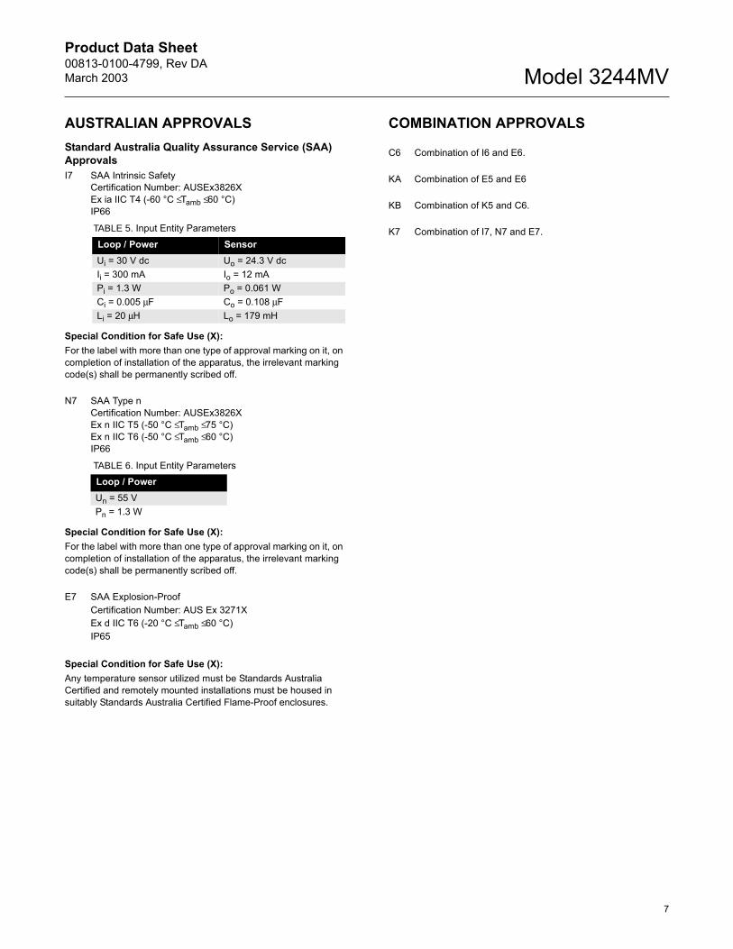
AUSTRALIAN APPROVALSStandard Australia Quality Assurance Service (SAA) ApprovalsI7 SAA Intrinsic Safety
Certification Number: AUSEx3826XEx ia IIC T4 (-60 °C ≤ Tamb ≤ 60 °C)IP66
Special Condition for Safe Use (X):For the label with more than one type of approval marking on it, on completion of installation of the apparatus, the irrelevant marking code(s) shall be permanently scribed off.
N7 SAA Type nCertification Number: AUSEx3826XEx n IIC T5 (-50 °C ≤ Tamb ≤ 75 °C)Ex n IIC T6 (-50 °C ≤ Tamb ≤ 60 °C)IP66
Special Condition for Safe Use (X):For the label with more than one type of approval marking on it, on completion of installation of the apparatus, the irrelevant marking code(s) shall be permanently scribed off.
E7 SAA Explosion-ProofCertification Number: AUS Ex 3271XEx d IIC T6 (-20 °C ≤ Tamb ≤ 60 °C)IP65
Special Condition for Safe Use (X):Any temperature sensor utilized must be Standards Australia Certified and remotely mounted installations must be housed in suitably Standards Australia Certified Flame-Proof enclosures.
COMBINATION APPROVALS
C6 Combination of I6 and E6.
KA Combination of E5 and E6
KB Combination of K5 and C6.
K7 Combination of I7, N7 and E7. TABLE 5. Input Entity ParametersLoop / Power SensorUi = 30 V dc Uo = 24.3 V dcIi = 300 mA Io = 12 mA Pi = 1.3 W Po = 0.061 WCi = 0.005 µF Co = 0.108 µFLi = 20 µH Lo = 179 mH
TABLE 6. Input Entity ParametersLoop / PowerUn = 55 V Pn = 1.3 W

Product Data Sheet00813-0100-4799, Rev DA
March 2003Model 3244MV
8
Dimensional DrawingsExploded View
Transmitter Dimensional DrawingsTop View Side View
Dimensions are in inches (millimeters)
Transmitter Dimensional Drawing for Conduits with M20 x 1.5, PG 13.5, and JIS G1/2 Entries
Top View Front View
Dimensions are in inches (millimeters)
Standard Cover with Wiring Diagram
Approvals Label
Housing Assembly with Permanent Terminal Block
Nameplate (includes serial number and model number)
Profibus-PA Electronics Module Assembly
LCD Meter (Optional)
LCD Meter Cover (Optional)
3244
-000
A03A
2.0 (51)
4.4 (112)
Standard Cover1/2-14 NPT Conduit Entry*
Meter Cover
Nameplate
3144
-020
4B02
A, 0
000A
07A
5.2 (132)
4.4 (112)
4.4 (112)
1/2-14 NPT Conduit Entry*3/8-16 UN-2B
4.4 (112)
2.0 (50.8)
5.20 (132)4.40 (112)
0.85 (21.6)*
* Clearance required to remove cover)
Adapters for M20 x 1.5, PG 13.5, and JIS G1/2 entries
3/816 UN2B 31
44-3
144A
021A
, A02
2A
4.40 (112) 1.17 (29.8)
0.94 (23.8)
0.21 (5.3)
4.00 (102)0.5
(12.7)
Adapters for M20 x 1.5, PG 13.5, and JIS G1/2 entries
Product Data Sheet00813-0100-4799, Rev DAMarch 2003
9
Model 3244MV
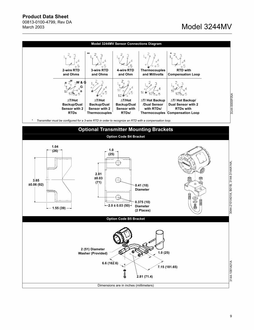
Model 3244MV Sensor Connections Diagram
* Transmitter must be configured for a 3-wire RTD in order to recognize an RTD with a compensation loop.
Optional Transmitter Mounting BracketsOption Code B4 Bracket
Option Code B5 Bracket
Dimensions are in inches (millimeters)
3144
-000
0F05
A
∆T/Hot Backup/Dual Sensor with 2
RTDs
∆T/Hot Backup/Dual Sensor with 2
Thermocouples
∆T/ Hot Backup /Dual Sensor with RTDs/
Thermocouples
∆T/Hot Backup/Dual Sensor with
RTDs/
2-wire RTD and Ohms
4-wire RTD and Ohm
Thermocouples and Millivolts
RTD with Compensation Loop
∆T/ Hot Backup/Dual Sensor with 2
RTDs with Compensation Loop
3-wire RTD and Ohms
RW W & G
GB
***
1.04 (26)
1.55 (39)
3.65 ±0.06 (92)
1.0(25)
2.81 ±0.03 (71)
0.41 (10)Diameter
0.375 (10)Diameter(2 Places)
2.0 ± 0.03 (50)
3044
-210
1A01
A; B
01B,
314
4-31
44A1
4A,
3144
-108
1A01
A
2 (51) Diameter Washer (Provided)
6.6 (162.6)
1.0 (25)
7.15 (181.65)
2.81 (71.4)
Product Data Sheet00813-0100-4799, Rev DA
March 2003Model 3244MV
10
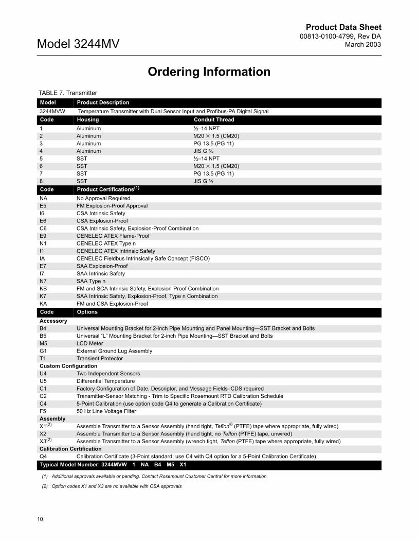
Ordering Information TABLE 7. Transmitter
Model Product Description3244MVW Temperature Transmitter with Dual Sensor Input and Profibus-PA Digital SignalCode Housing Conduit Thread1 Aluminum ½14 NPT2 Aluminum M20 1.5 (CM20)3 Aluminum PG 13.5 (PG 11)4 Aluminum JIS G ½5 SST ½14 NPT6 SST M20 1.5 (CM20)7 SST PG 13.5 (PG 11)8 SST JIS G ½Code Product Certifications(1)
(1) Additional approvals available or pending. Contact Rosemount Customer Central for more information.
NA No Approval RequiredE5 FM Explosion-Proof ApprovalI6 CSA Intrinsic SafetyE6 CSA Explosion-ProofC6 CSA Intrinsic Safety, Explosion-Proof CombinationE9 CENELEC ATEX Flame-ProofN1 CENELEC ATEX Type nI1 CENELEC ATEX Intrinsic SafetyIA CENELEC Fieldbus Intrinsically Safe Concept (FISCO)E7 SAA Explosion-ProofI7 SAA Intrinsic SafetyN7 SAA Type nKB FM and SCA Intrinsic Safety, Explosion-Proof CombinationK7 SAA Intrinsic Safety, Explosion-Proof, Type n CombinationKA FM and CSA Explosion-ProofCode OptionsAccessoryB4 Universal Mounting Bracket for 2-inch Pipe Mounting and Panel MountingSST Bracket and BoltsB5 Universal L Mounting Bracket for 2-inch Pipe MountingSST Bracket and BoltsM5 LCD MeterG1 External Ground Lug AssemblyT1 Transient ProtectorCustom ConfigurationU4 Two Independent SensorsU5 Differential TemperatureC1 Factory Configuration of Date, Descriptor, and Message FieldsCDS requiredC2 Transmitter-Sensor Matching - Trim to Specific Rosemount RTD Calibration ScheduleC4 5-Point Calibration (use option code Q4 to generate a Calibration Certificate)F5 50 Hz Line Voltage FilterAssemblyX1(2)
(2) Option codes X1 and X3 are no available with CSA approvals
Assemble Transmitter to a Sensor Assembly (hand tight, Teflon® (PTFE) tape where appropriate, fully wired)X2 Assemble Transmitter to a Sensor Assembly (hand tight, no Teflon (PTFE) tape, unwired)X3(2) Assemble Transmitter to a Sensor Assembly (wrench tight, Teflon (PTFE) tape where appropriate, fully wired)Calibration CertificationQ4 Calibration Certificate (3-Point standard; use C4 with Q4 option for a 5-Point Calibration Certificate)Typical Model Number: 3244MVW 1 NA B4 M5 X1
Product Data Sheet00813-0100-4799, Rev DAMarch 2003
11
Model 3244MV
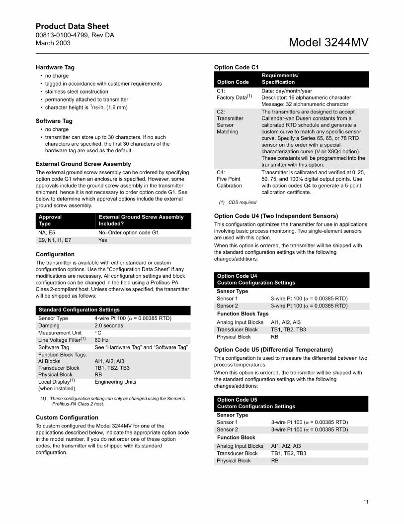
Hardware Tag no charge tagged in accordance with customer requirements stainless steel construction permanently attached to transmitter character height is 1/16-in. (1.6 mm)
Software Tag no charge transmitter can store up to 30 characters. If no such
characters are specified, the first 30 characters of the hardware tag are used as the default.
External Ground Screw AssemblyThe external ground screw assembly can be ordered by specifying option code G1 when an enclosure is specified. However, some approvals include the ground screw assembly in the transmitter shipment, hence it is not necessary to order option code G1. See below to determine which approval options include the external ground screw assembly.
ConfigurationThe transmitter is available with either standard or custom configuration options. Use the Configuration Data Sheet if any modifications are necessary. All configuration settings and block configuration can be changed in the field using a Profibus-PA Class 2-compliant host. Unless otherwise specified, the transmitter will be shipped as follows:
Custom ConfigurationTo custom configured the Model 3244MV for one of the applications described below, indicate the appropriate option code in the model number. If you do not order one of these option codes, the transmitter will be shipped with its standard configuration.
Option Code C1
Option Code U4 (Two Independent Sensors)This configuration optimizes the transmitter for use in applications involving basic process monitoring. Two single-element sensors are used with this option. When this option is ordered, the transmitter will be shipped with the standard configuration settings with the following changes/additions:
Option Code U5 (Differential Temperature)This configuration is used to measure the differential between two process temperatures.When this option is ordered, the transmitter will be shipped with the standard configuration settings with the following changes/additions:
Approval Type
External Ground Screw Assembly Included?
NA, E5 NoOrder option code G1 E9, N1, I1, E7 Yes
Standard Configuration Settings Sensor Type 4-wire Pt 100 ( = 0.00385 RTD)Damping 2.0 secondsMeasurement Unit ° CLine Voltage Filter(1)
(1) These configuration setting can only be changed using the Siemens Profibus-PA Class 2 host.
60 HzSoftware Tag See Hardware Tag and Software TagFunction Block Tags:AI BlocksTransducer BlockPhysical Block
AI1, AI2, AI3TB1, TB2, TB3RB
Local Display(1) (when installed)
Engineering Units
Option CodeRequirements/Specification
C1:Factory Data(1)
(1) CDS required
Date: day/month/yearDescriptor: 16 alphanumeric characterMessage: 32 alphanumeric character
C2:Transmitter Sensor Matching
The transmitters are designed to accept Callendar-van Dusen constants from a calibrated RTD schedule and generate a custom curve to match any specific sensor curve. Specify a Series 65, 65, or 78 RTD sensor on the order with a special characterization curve (V or X8Q4 option). These constants will be programmed into the transmitter with this option.
C4:Five Point Calibration
Transmitter is calibrated and verified at 0, 25, 50, 75, and 100% digital output points. Use with option codes Q4 to generate a 5-point calibration certificate.
Option Code U4Custom Configuration SettingsSensor TypeSensor 1 3-wire Pt 100 ( = 0.00385 RTD)Sensor 2 3-wire Pt 100 ( = 0.00385 RTD)Function Block Tags:Analog Input Blocks AI1, AI2, AI3Transducer Block TB1, TB2, TB3Physical Block RB
Option Code U5Custom Configuration SettingsSensor TypeSensor 1 3-wire Pt 100 ( = 0.00385 RTD)Sensor 2 3-wire Pt 100 ( = 0.00385 RTD)Function Block Tags:Analog Input Blocks AI1, AI2, AI3Transducer Block TB1, TB2, TB3Physical Block RB
Product Data Sheet00813-0100-4799, Rev DAMarch 2003 Model 3244MV
Emerson Process Management
© 2003 Rosemount, Inc.
Rosemount and the Rosemount logotype are registered trademarks of Rosemount Inc.MultiVariable is a trademark of Rosemount Inc.Teflon is a registered trademark of E.I du Pont de Nemours & Co.HART is a registered trademark of the HART Foundation.FOUNDATION is a trademark of the Fieldbus Foundation.All other marks are the property of their respective owners.
¢00813-0100-4799W¤
Rosemount Temperature GmbHFrankenstrasse 2163791 KarlsteinGermanyT 49 (6188) 992 0F 49 (6188) 992 112
Emerson Process Management Asia Pacific Private Limited1 Pandan CrescentSingapore 128461T (65) 6777 8211F (65) 6777 [email protected]
Rosemount Inc.8200 Market BoulevardChanhassen, MN 55317 USAT (U.S.) 1-800-999-9307T (International) (952) 906-8888F (952) 949-7001
www.rosemount.com
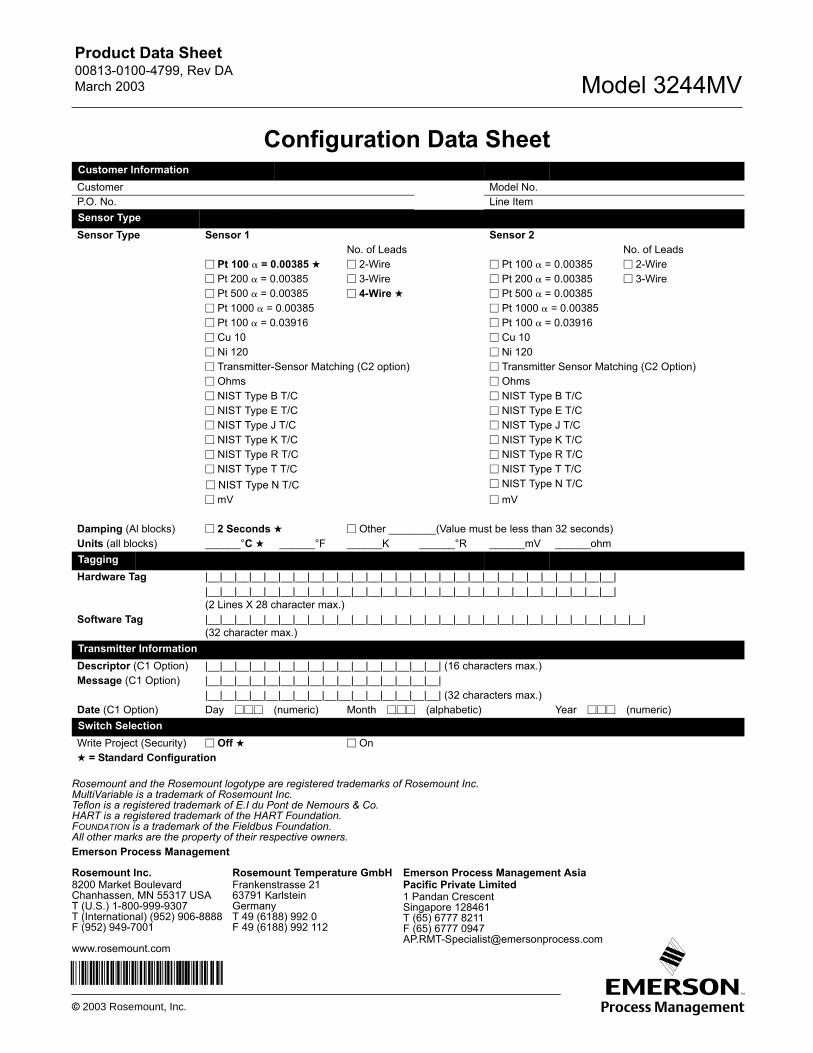
Configuration Data SheetCustomer InformationCustomer Model No.P.O. No. Line ItemSensor TypeSensor Type Sensor 1 Sensor 2
No. of Leads No. of Leads Pt 100 = 0.00385 2-Wire Pt 100 = 0.00385 2-Wire Pt 200 = 0.00385 3-Wire Pt 200 = 0.00385 3-Wire Pt 500 = 0.00385 4-Wire Pt 500 = 0.00385 Pt 1000 = 0.00385 Pt 1000 = 0.00385 Pt 100 = 0.03916 Pt 100 = 0.03916 Cu 10 Cu 10 Ni 120 Ni 120 Transmitter-Sensor Matching (C2 option) Transmitter Sensor Matching (C2 Option) Ohms Ohms NIST Type B T/C NIST Type B T/C NIST Type E T/C NIST Type E T/C NIST Type J T/C NIST Type J T/C NIST Type K T/C NIST Type K T/C NIST Type R T/C NIST Type R T/C NIST Type T T/C NIST Type T T/C NIST Type N T/C NIST Type N T/C mV mV
Damping (Al blocks) 2 Seconds Other ________(Value must be less than 32 seconds)Units (all blocks) ______°C ______°F ______K ______°R ______mV ______ohmTaggingHardware Tag |__|__|__|__|__|__|__|__|__|__|__|__|__|__|__|__|__|__|__|__|__|__|__|__|__|__|__|__|
|__|__|__|__|__|__|__|__|__|__|__|__|__|__|__|__|__|__|__|__|__|__|__|__|__|__|__|__|(2 Lines X 28 character max.)
Software Tag |__|__|__|__|__|__|__|__|__|__|__|__|__|__|__|__|__|__|__|__|__|__|__|__|__|__|__|__|__|__|(32 character max.)
Transmitter InformationDescriptor (C1 Option) |__|__|__|__|__|__|__|__|__|__|__|__|__|__|__|__| (16 characters max.)Message (C1 Option) |__|__|__|__|__|__|__|__|__|__|__|__|__|__|__|__|
|__|__|__|__|__|__|__|__|__|__|__|__|__|__|__|__| (32 characters max.)Date (C1 Option) Day (numeric) Month (alphabetic) Year (numeric)Switch SelectionWrite Project (Security) Off On = Standard Configuration