Embed Size (px)
Citation preview
86
Model 106-AC Anti-Cavitation Control Valve
2011.2
Product OverviewThe 106-AC series control valve is designed to solve high pressure drop problems by allowing smooth control and protection from cavitation damage. It’s ideal for applications where large pressure differentials preclude the use of standard automatic control valves and varying flows make orifice plates ineffective.
The AC control valve contains two heavy stainless steel sliding cages that maximize the full flow capacity. The first cage directs and contains the cavitation recovery, allowing it to dissipate harmlessly. While the second cage allows further control to a level as low as atmospheric pressure downstream. The cages are engineered to meet the flow / pressure differential of each application.
Product Line Drawing
KEY FEATURES• Solves high pressure drop problems• Controls variable flows & vibration• Significantly reduces noise• Self-contained – actuators
not required• Customizable to meet your
application needs
1. Removable Stem Cap2. ASTM A536 Ductile Iron Con-
struction3. 316 Stainless Steel Stem4. Buna-N / EPDM Diaphragm 5. Buna-N / EPDM Resilient Disc6. 316 Stainless Steel Seat7. Cavitation Recovery Chamber8. NSF 61 Fusion Bonded Epoxy
Coating
2
6
5
1
7
8
34
106-PG-AC Globe
Main Valves – O
ptions
www.singervalve.com87
Model 106-AC Anti-Cavitation Control Valve
2011.2
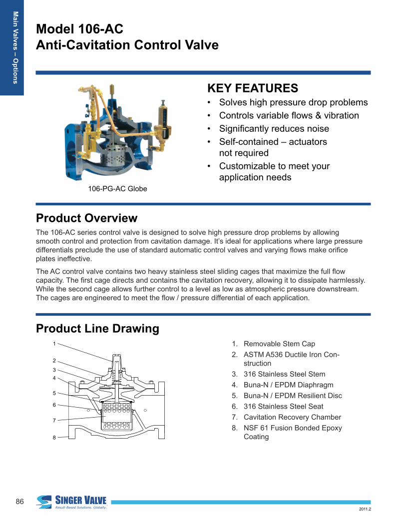
Singer model 106-PR-AC Large elevation head creating 200 - 250 psi / 13.8 - 17.2 bar
Distribution to users at a relatively constant 20 psi / 1.38 bar over the flow range of 100 to 1,200 USGPM / 6.3 to 75.7 L/s
Typical ApplicationPressure ReducingYour application has a maximum continuous design flow of 1200 USGPM / 75.6 L/s and a minimum of 100 USGPM / 6.3 L/s. The inlet pressure ranges from 200 psi / 13.8 bar at a maximum flow to 250 psi / 17.24 bar at minimum flow. You need a relatively constant outlet pressure of 20 psi / 1.38 bar. There is a possibility of demand for 2000 USGPM / 126.2 L/s.
See Performance Curve 106-415, page 282Differential Pressure acceptable:ranges from 180 to 230 psi / 12.4 to 15.9 bar, which is always less than maximum 300 psi / 20.7 bar• application OK
Differential Ratio acceptable:minimum differential 180 psi / 12.40 bar is greater than 50% of maximum 230 psi / 15.9 bar • application OK
1200 USGPM / 75.7 L/s flow:above solid line for 4 in /100 mm – 880 USGPM / 55.5 L/s • valve too small below solid line for 6 in / 150 mm – 1,800 USGPM / 113.6 L/s • OK for continuous operation
2000 USGPM / 126.2 L/s flow:
below dotted line for 6 in / 150 mm / 2,200 USGPM / 138.8 L/s• OK for intermittent operation select 8 in / 200 mm for continuous operation at 2,000 USGPM / 126.2 L/s
Selection Pressure Reducing: 6 in / 150 mm Singer model 106-PR-AC, ANSI Class 150 flange, range 10 – 80 psi / 0.7 bar – 5.5 bar, set at 20 psi / 1.38 bar
Main Valves – O
ptions
88
Model 106-AC Anti-Cavitation Control Valve
2011.2
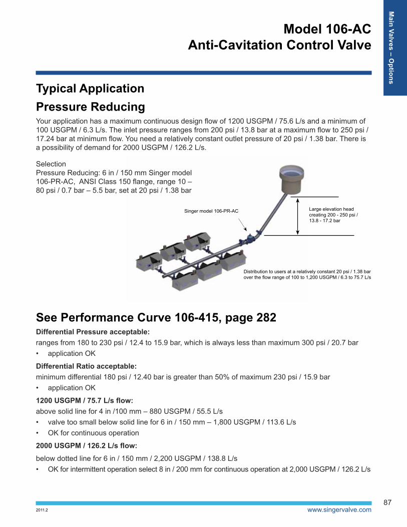
Typical ApplicationContinuous ReliefYour application requires the discharge pressure of a fixed speed pump to be limited to 110 psi / 7.6 bar. The pump is designed for 1200 USGPM / 75.7 L/s at 100 psi / 6.9 bar. The maximum shut-off pressure is 160 psi / 11 bar.
The relief valve will discharge back to the reservoir (atmosphere), when system demand is low but the pump is still required to operate. See Performance Curve 106-415, page 282
Differential Pressure acceptable: 110 psi / 7.6 bar to atmosphere, which is always less than maximum 300 psi / 20.7 bar
Differential Ratio acceptable: Constant
Up to 1200 USGPM / 75.7 L/s:• Above dashed line for 4 in / 100 mm – 4 in / 100 mm too small• Below solid line for 6 in / 150 mm – 1,800 USGPM / 113.6 L/s• OK for continuous operation.
To control surging caused by pump starting and stopping, combine the RPS function with pump control valve functions. Contact Singer Valve for more details.
Tank Supply Insufficient to meet Peak Demand
Singer model 106-RPS-AC or Singer model DW(X)-RPS-ACset at 110 psi / 7.6 bar
Old distribution zone to users: Maximum 110 psi / 7.6 bar
Selection – Relief Function: 6 in / 150 mm Singer model 106-RPS-AC, ANSI Class 150 flanged range 20 psi to 200 psi / 1.38 bar to 13.8 bar, set at 110 psi / 7.6 bar. Or ...
Selection – Pump Control and Relief Function: 6 in / 150 mm Singer model 106-DW-RPS-AC, ANSI Class 150 flanged range 20 psi to 200 psi / 1.38 bar to 13.8 bar, set at 110 psi / 7.6 bar.
Main Valves – O
ptions
www.singervalve.com89
Model 106-AC Anti-Cavitation Control Valve
2011.2
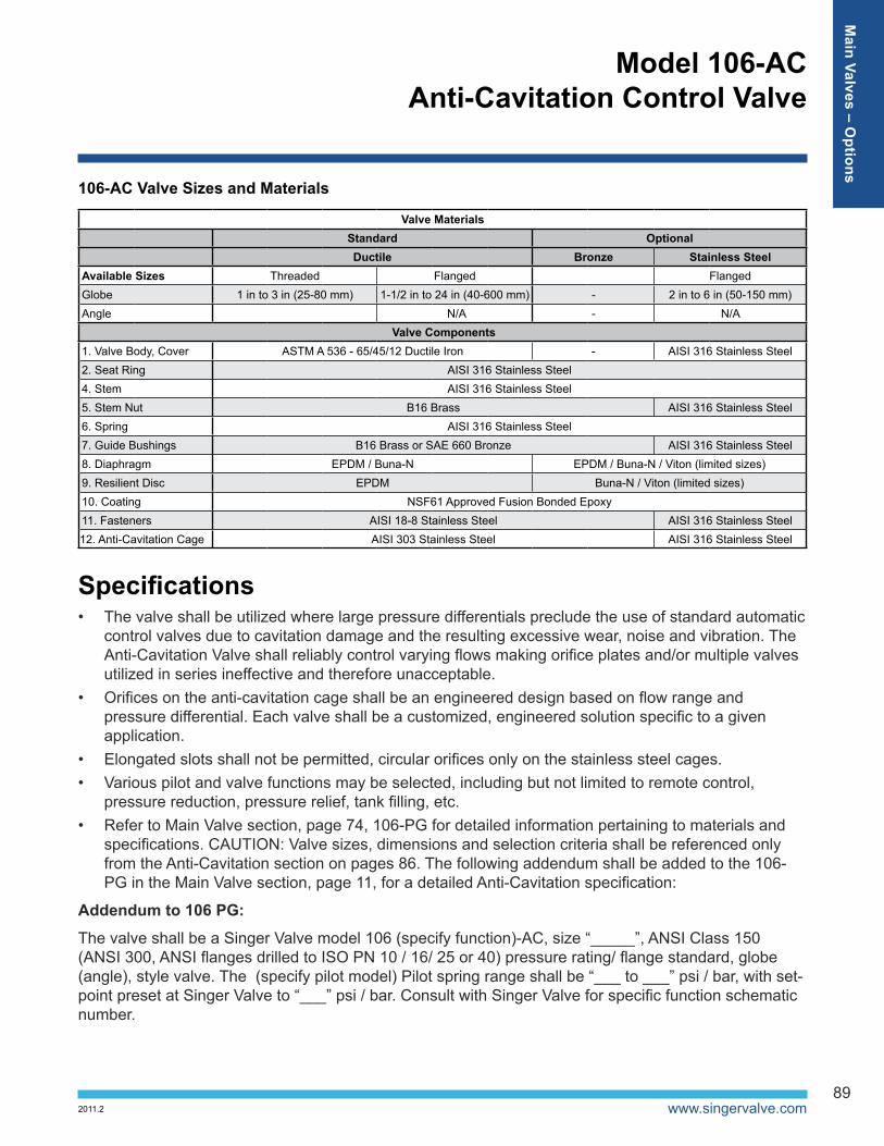
106-AC Valve Sizes and Materials
Valve MaterialsStandard OptionalDuctile Bronze Stainless Steel
Available Sizes Threaded Flanged Flanged Globe 1 in to 3 in (25-80 mm) 1-1/2 in to 24 in (40-600 mm) - 2 in to 6 in (50-150 mm)Angle N/A - N/A
Valve Components1. Valve Body, Cover ASTM A 536 - 65/45/12 Ductile Iron - AISI 316 Stainless Steel2. Seat Ring AISI 316 Stainless Steel4. Stem AISI 316 Stainless Steel5. Stem Nut B16 Brass AISI 316 Stainless Steel6. Spring AISI 316 Stainless Steel7. Guide Bushings B16 Brass or SAE 660 Bronze AISI 316 Stainless Steel8. Diaphragm EPDM / Buna-N EPDM / Buna-N / Viton (limited sizes)9. Resilient Disc EPDM Buna-N / Viton (limited sizes)10. Coating NSF61 Approved Fusion Bonded Epoxy11. Fasteners AISI 18-8 Stainless Steel AISI 316 Stainless Steel12. Anti-Cavitation Cage AISI 303 Stainless Steel AISI 316 Stainless Steel
Specifications• The valve shall be utilized where large pressure differentials preclude the use of standard automatic
control valves due to cavitation damage and the resulting excessive wear, noise and vibration. The Anti-Cavitation Valve shall reliably control varying flows making orifice plates and/or multiple valves utilized in series ineffective and therefore unacceptable.
• Orifices on the anti-cavitation cage shall be an engineered design based on flow range and pressure differential. Each valve shall be a customized, engineered solution specific to a given application.
• Elongated slots shall not be permitted, circular orifices only on the stainless steel cages.• Various pilot and valve functions may be selected, including but not limited to remote control,
pressure reduction, pressure relief, tank filling, etc.• Refer to Main Valve section, page 74, 106-PG for detailed information pertaining to materials and
specifications. CAUTION: Valve sizes, dimensions and selection criteria shall be referenced only from the Anti-Cavitation section on pages 86. The following addendum shall be added to the 106-PG in the Main Valve section, page 11, for a detailed Anti-Cavitation specification:
Addendum to 106 PG:
The valve shall be a Singer Valve model 106 (specify function)-AC, size “_____”, ANSI Class 150 (ANSI 300, ANSI flanges drilled to ISO PN 10 / 16/ 25 or 40) pressure rating/ flange standard, globe (angle), style valve. The (specify pilot model) Pilot spring range shall be “___ to ___” psi / bar, with set-point preset at Singer Valve to “___” psi / bar. Consult with Singer Valve for specific function schematic number.
Main Valves – O
ptions
90
Model 106-AC Anti-Cavitation Control Valve
2011.2
• Anti-Cavitation trim shall be utilized in Singer 106 (full port), globe style valves. Anti-Cavitation trim will be incorporated in new production only.
• The valve shall have heavy wall stainless steel cages with round orifices optimized for a specific application. Elongated slots shall not be permitted.
• The bottom cage shall remain stationary. On valves 2 1/2 in / 65 mm and smaller the cage shall be threaded in place. On valves 3 in / 80 mm and larger the cages shall be bolted in place, utilizing Spiralock thread tapping technology.
• The upper cage shall be attached to the valve actuator and will modulate as required to suit the requirements of the specific application.
• Anti-Cavitation trim will contain cavitation while reducing noise and vibration substantially.• The valve shall effectively contain the cavitation recovery from low to full flow without carry over.
Transferring the problem to an orifice plate downstream is not acceptable.• The Anti-Cavitation valve supplier shall have at least 10 years of successful installations of similar
applications.
Refer to Pilot and Accessories section, page 249, for detailed information pertaining to materials and specifications on the many pilots that can be utilized with the Anti-Cavitation control valve. For additional engineering notes, refer to page 285.
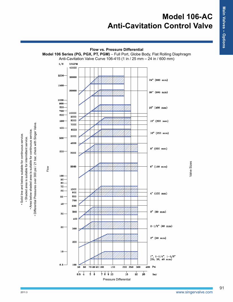
Pressure DifferentialUsing the Performance Curves 106-415 (page 282), select the smallest valve that has the flow capacity that meets or exceeds the flow required, at a pressure differential less than the minimum available in the application.
Ensure that all of the operating conditions (should they vary) for your application fall below the curve for the valve selected.
The solid lines show the maximum continuous flow capacity for a fully open valve, for a given size, at the chosen pressure differential.
If the inlet pressure varies widely, it may not be possible to obtain the maximum desired flow at times of low pressure differential. Be sure to consult with Singer Valve if:• the pressure differential is over 300 psi / 20.7 bar• the pressure differential drops below 50% of the maximum differential pressure• the downstream pressure is sub-atmospheric• the fluid is other than clean, cool water
Ordering InstructionsRefer to page 286 for the order form and ordering instructions.
Additionally, include the following information for this product:1. Inlet / outlet pressure range2. Minimum / maximum differential pressure3. Minimum / maximum flow rate
Main Valves – O
ptions
www.singervalve.com91
Model 106-AC Anti-Cavitation Control Valve
2011.3
Flow vs. Pressure DifferentialModel 106 Series (PG, PGX, PT, PGM) – Full Port, Globe Body, Flat Rolling Diaphragm
Anti-Cavitation Valve Curve 106-415 (1 in / 25 mm – 24 in / 600 mm)
Flow
Pressure Differential
Valv
e S
izes
• Sol
id li
ne a
nd b
elow
sui
tabl
e fo
r con
tinuo
us s
ervi
ce.
• Sha
ded
area
is s
uita
ble
for i
nter
mitt
ent s
ervi
ce.
• Are
a be
low
sha
ded
area
is s
uita
ble
for c
ontin
uous
ser
vice
. • D
iffer
entia
l Pre
ssur
es o
ver 3
00 p
si /
21 b
ar, c
heck
with
Sin
ger V
alve
.
Main Valves – O
ptions
92
Model 106-AC Anti-Cavitation Control Valve
2011.2
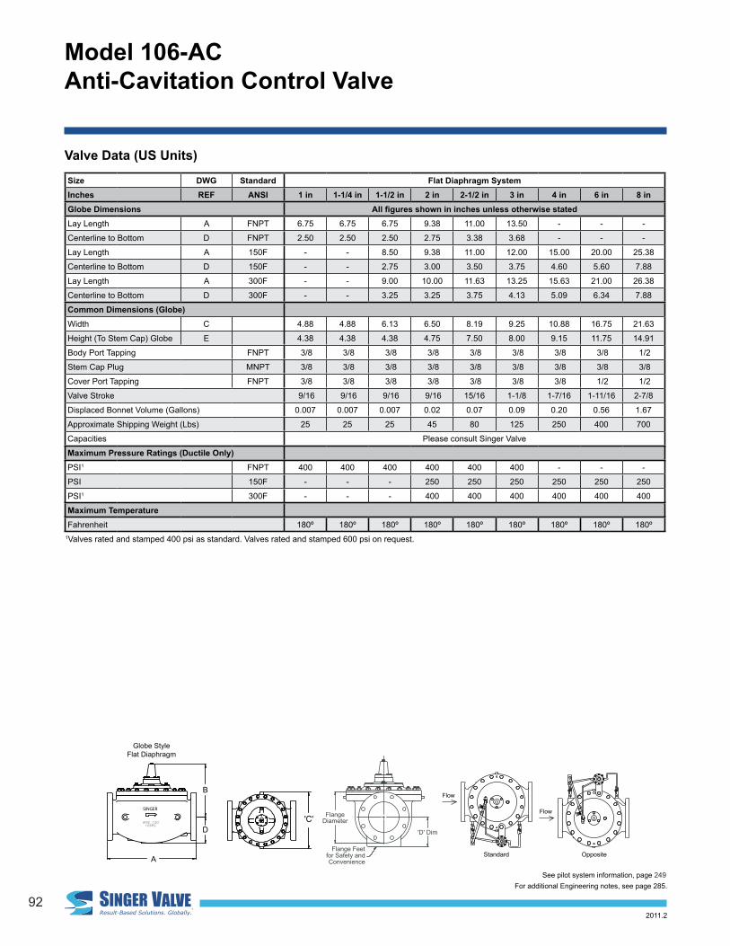
Valve Data (US Units)
Flange Feetfor Safety andConvenience
FlangeDiameter
'D' Dim
'A' 'B'
'E' 'E'
'F'
'B'
'E'
'F''D'
'A'
'E'
'D'
'C'
Flow
Standard
Flow
Opposite
SINGER
ansi QUPsQPVpgMac
E
D
A
SINGER
D
B
ansi QUPQPVpg
AE RGNIS
C
Globe Style Flat Diaphragm
Size DWG Standard Flat Diaphragm SystemInches REF ANSI 1 in 1-1/4 in 1-1/2 in 2 in 2-1/2 in 3 in 4 in 6 in 8 inGlobe Dimensions All figures shown in inches unless otherwise statedLay Length A FNPT 6.75 6.75 6.75 9.38 11.00 13.50 - - -
Centerline to Bottom D FNPT 2.50 2.50 2.50 2.75 3.38 3.68 - - -
Lay Length A 150F - - 8.50 9.38 11.00 12.00 15.00 20.00 25.38
Centerline to Bottom D 150F - - 2.75 3.00 3.50 3.75 4.60 5.60 7.88
Lay Length A 300F - - 9.00 10.00 11.63 13.25 15.63 21.00 26.38
Centerline to Bottom D 300F - - 3.25 3.25 3.75 4.13 5.09 6.34 7.88
Common Dimensions (Globe)Width C 4.88 4.88 6.13 6.50 8.19 9.25 10.88 16.75 21.63
Height (To Stem Cap) Globe E 4.38 4.38 4.38 4.75 7.50 8.00 9.15 11.75 14.91
Body Port Tapping FNPT 3/8 3/8 3/8 3/8 3/8 3/8 3/8 3/8 1/2
Stem Cap Plug MNPT 3/8 3/8 3/8 3/8 3/8 3/8 3/8 3/8 3/8
Cover Port Tapping FNPT 3/8 3/8 3/8 3/8 3/8 3/8 3/8 1/2 1/2
Valve Stroke 9/16 9/16 9/16 9/16 15/16 1-1/8 1-7/16 1-11/16 2-7/8
Displaced Bonnet Volume (Gallons) 0.007 0.007 0.007 0.02 0.07 0.09 0.20 0.56 1.67
Approximate Shipping Weight (Lbs) 25 25 25 45 80 125 250 400 700
Capacities Please consult Singer Valve
Maximum Pressure Ratings (Ductile Only)PSI1 FNPT 400 400 400 400 400 400 - - -
PSI 150F - - - 250 250 250 250 250 250
PSI1 300F - - - 400 400 400 400 400 400
Maximum TemperatureFahrenheit 180º 180º 180º 180º 180º 180º 180º 180º 180º
1Valves rated and stamped 400 psi as standard. Valves rated and stamped 600 psi on request.
See pilot system information, page 249For additional Engineering notes, see page 285.

www.singervalve.com93
Model 106-AC Anti-Cavitation Control Valve
2011.2
Size DWG Standard Flat Diaphragm SystemInches REF ANSI 1 in 1-1/4 in 1-1/2 in 2 in 2-1/2 in 3 in 4 in 6 in 8 inGlobe Dimensions All figures shown in inches unless otherwise statedLay Length A FNPT 6.75 6.75 6.75 9.38 11.00 13.50 - - -
Centerline to Bottom D FNPT 2.50 2.50 2.50 2.75 3.38 3.68 - - -
Lay Length A 150F - - 8.50 9.38 11.00 12.00 15.00 20.00 25.38
Centerline to Bottom D 150F - - 2.75 3.00 3.50 3.75 4.60 5.60 7.88
Lay Length A 300F - - 9.00 10.00 11.63 13.25 15.63 21.00 26.38
Centerline to Bottom D 300F - - 3.25 3.25 3.75 4.13 5.09 6.34 7.88
Common Dimensions (Globe)Width C 4.88 4.88 6.13 6.50 8.19 9.25 10.88 16.75 21.63
Height (To Stem Cap) Globe E 4.38 4.38 4.38 4.75 7.50 8.00 9.15 11.75 14.91
Body Port Tapping FNPT 3/8 3/8 3/8 3/8 3/8 3/8 3/8 3/8 1/2
Stem Cap Plug MNPT 3/8 3/8 3/8 3/8 3/8 3/8 3/8 3/8 3/8
Cover Port Tapping FNPT 3/8 3/8 3/8 3/8 3/8 3/8 3/8 1/2 1/2
Valve Stroke 9/16 9/16 9/16 9/16 15/16 1-1/8 1-7/16 1-11/16 2-7/8
Displaced Bonnet Volume (Gallons) 0.007 0.007 0.007 0.02 0.07 0.09 0.20 0.56 1.67
Approximate Shipping Weight (Lbs) 25 25 25 45 80 125 250 400 700
Capacities Please consult Singer Valve
Maximum Pressure Ratings (Ductile Only)PSI1 FNPT 400 400 400 400 400 400 - - -
PSI 150F - - - 250 250 250 250 250 250
PSI1 300F - - - 400 400 400 400 400 400
Maximum TemperatureFahrenheit 180º 180º 180º 180º 180º 180º 180º 180º 180º
1Valves rated and stamped 400 psi as standard. Valves rated and stamped 600 psi on request.
Valve Data (US Units)
Flange Feetfor Safety andConvenience
FlangeDiameter
'D' Dim
'A' 'B'
'E' 'E'
'F'
'B'
'E'
'F''D'
'A'
'E'
'D'
'C'
Flow
Standard
Flow
Opposite
SINGER
ansi QUPsQPVpgMac
E
D
A
SINGER
D
B
ansi QUPQPVpg
AE RGNIS
C
Globe Style Rolling Diaphragm
Size DWG Standard Rolling Diaphragm SystemInches REF ANSI 6 in 8 in 10 in 12 in 16 in 20 in 24 inGlobe Dimensions All figures shown in inches unless otherwise statedLay Length A FNPT - - - - - - -
Centerline to Bottom D FNPT - - - - - - -
Lay Length A 150F 20.00 25.38 29.75 34.00 41.38 52.00 61.50
Centerline to Bottom D 150F 5.60 7.63 8.25 9.62 12.13 14.43 17.13
Lay Length A 300F 21.00 26.38 31.13 35.50 43.50 53.62 63.25
Centerline to Bottom D 300F 6.34 7.88 9.00 10.38 13.13 15.75 19.65
Common Dimensions (Globe & Angle)Width C 12.75 16.09 18.00 21.25 27.06 35.00 49.68
Height (To Stem Cap) Globe E 13.62 17.93 22.13 23.75 30.31 35.50 45.75
Body Port Tapping FNPT 3/8 1/2 3/4 3/4 3/4 3/4 3/4
Stem Cap Plug MNPT 3/8 3/8 3/4 3/4 3/4 3/4 3/4
Cover Port Tapping FNPT 1/2 1/2 3/4 3/4 3/4 3/4 3/4
Valve Stroke 1-11/16 2-7/8 3-1/4 3-3/4 4-3/4 5-9/16 6
Displaced Bonnet Volume (Gallons) 0.5 1.0 1.5 2.3 6.8 9.0 14.8
Approximate Shipping Weight (Lbs) 360 660 900 1400 2400 3450 5300
Flow Capacities Please consult Singer Valve
Maximum Pressure Ratings (Ductile Only)PSI1 FNPT - - - - - - -
PSI 150F 250 250 250 250 250 250 250
PSI1 300F 400 400 400 400 400 400 400
Maximum TemperatureFahrenheit 180º 180º 180º 180º 180º 180º 180º
1Valves rated and stamped 400 psi as standard. Valves rated and stamped 600 psi on request.
See pilot system information, page 249For additional Engineering notes, see page 285.
Main Valves – O
ptions
94
Model 106-AC Anti-Cavitation Control Valve
2011.2
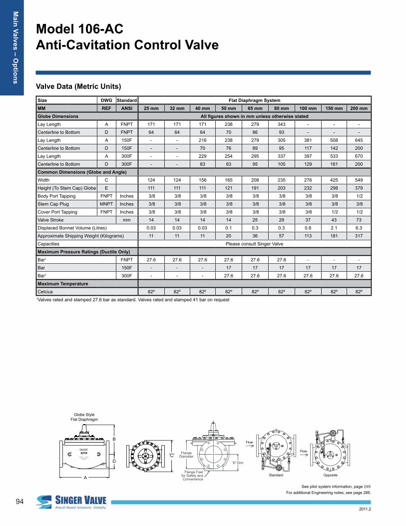
Valve Data (Metric Units)
Flange Feetfor Safety andConvenience
FlangeDiameter
'D' Dim
'A' 'B'
'E' 'E'
'F'
'B'
'E'
'F''D'
'A'
'E'
'D'
'C'
Flow
Standard
Flow
Opposite
SINGER
ansi QUPsQPVpgMac
E
D
A
SINGER
D
B
ansi QUPQPVpg
AE RGNIS
C
Globe Style Flat Diaphragm
Size DWG Standard Flat Diaphragm SystemMM REF ANSI 25 mm 32 mm 40 mm 50 mm 65 mm 80 mm 100 mm 150 mm 200 mmGlobe Dimensions All figures shown in mm unless otherwise statedLay Length A FNPT 171 171 171 238 279 343 - - -
Centerline to Bottom D FNPT 64 64 64 70 86 93 - - -
Lay Length A 150F - - 216 238 279 305 381 508 645
Centerline to Bottom D 150F - - 70 76 89 95 117 142 200
Lay Length A 300F - - 229 254 295 337 397 533 670
Centerline to Bottom D 300F - - 83 83 95 105 129 161 200
Common Dimensions (Globe and Angle)Width C 124 124 156 165 208 235 276 425 549
Height (To Stem Cap) Globe E 111 111 111 121 191 203 232 298 379
Body Port Tapping FNPT Inches 3/8 3/8 3/8 3/8 3/8 3/8 3/8 3/8 1/2
Stem Cap Plug MNPT Inches 3/8 3/8 3/8 3/8 3/8 3/8 3/8 3/8 3/8
Cover Port Tapping FNPT Inches 3/8 3/8 3/8 3/8 3/8 3/8 3/8 1/2 1/2
Valve Stroke mm 14 14 14 14 25 29 37 43 73
Displaced Bonnet Volume (Litres) 0.03 0.03 0.03 0.1 0.3 0.3 0.8 2.1 6.3
Approximate Shipping Weight (Kilograms) 11 11 11 20 36 57 113 181 317
Capacities Please consult Singer Valve
Maximum Pressure Ratings (Ductile Only)Bar1 FNPT 27.6 27.6 27.6 27.6 27.6 27.6 - - -
Bar 150F - - - 17 17 17 17 17 17
Bar1 300F - - - 27.6 27.6 27.6 27.6 27.6 27.6
Maximum TemperatureCelcius 82º 82º 82º 82º 82º 82º 82º 82º 82º
1Valves rated and stamped 27.6 bar as standard. Valves rated and stamped 41 bar on request
See pilot system information, page 249For additional Engineering notes, see page 285.
Main Valves – O
ptions

www.singervalve.com95
Model 106-AC Anti-Cavitation Control Valve
2011.2
Size DWG Standard Flat Diaphragm SystemMM REF ANSI 25 mm 32 mm 40 mm 50 mm 65 mm 80 mm 100 mm 150 mm 200 mmGlobe Dimensions All figures shown in mm unless otherwise statedLay Length A FNPT 171 171 171 238 279 343 - - -
Centerline to Bottom D FNPT 64 64 64 70 86 93 - - -
Lay Length A 150F - - 216 238 279 305 381 508 645
Centerline to Bottom D 150F - - 70 76 89 95 117 142 200
Lay Length A 300F - - 229 254 295 337 397 533 670
Centerline to Bottom D 300F - - 83 83 95 105 129 161 200
Common Dimensions (Globe and Angle)Width C 124 124 156 165 208 235 276 425 549
Height (To Stem Cap) Globe E 111 111 111 121 191 203 232 298 379
Body Port Tapping FNPT Inches 3/8 3/8 3/8 3/8 3/8 3/8 3/8 3/8 1/2
Stem Cap Plug MNPT Inches 3/8 3/8 3/8 3/8 3/8 3/8 3/8 3/8 3/8
Cover Port Tapping FNPT Inches 3/8 3/8 3/8 3/8 3/8 3/8 3/8 1/2 1/2
Valve Stroke mm 14 14 14 14 25 29 37 43 73
Displaced Bonnet Volume (Litres) 0.03 0.03 0.03 0.1 0.3 0.3 0.8 2.1 6.3
Approximate Shipping Weight (Kilograms) 11 11 11 20 36 57 113 181 317
Capacities Please consult Singer Valve
Maximum Pressure Ratings (Ductile Only)Bar1 FNPT 27.6 27.6 27.6 27.6 27.6 27.6 - - -
Bar 150F - - - 17 17 17 17 17 17
Bar1 300F - - - 27.6 27.6 27.6 27.6 27.6 27.6
Maximum TemperatureCelcius 82º 82º 82º 82º 82º 82º 82º 82º 82º
1Valves rated and stamped 27.6 bar as standard. Valves rated and stamped 41 bar on request
Valve Data (Metric Units)
Flange Feetfor Safety andConvenience
FlangeDiameter
'D' Dim
'A' 'B'
'E' 'E'
'F'
'B'
'E'
'F''D'
'A'
'E'
'D'
'C'
Flow
Standard
Flow
Opposite
SINGER
ansi QUPsQPVpgMac
E
D
A
SINGER
D
B
ansi QUPQPVpg
AE RGNIS
C
Globe Style Rolling Diaphragm
Size DWG Standard Rolling Diaphragm Systemmm REF ANSI 150 mm 200 mm 250 mm 300 mm 400 mm 500 mm 600 mmGlobe Dimensions All figures shown in mm unless otherwise stated.Lay Length A FNPT - - - - - - -
Centerline to Bottom D FNPT - - - - - - -
Lay Length A 150F 508 645 756 864 1051 1321 1562
Centerline to Bottom D 150F 142 194 210 244 308 367 435
Lay Length A 300F 533 670 791 902 1105 1362 1607
Centerline to Bottom D 300F 161 200 229 264 334 400 499
Common Dimensions (Globe)
Width C 324 409 460 540 687 889 1262
Height (To Stem Cap) Globe E 346 455 562 603 770 902 1162
Body Port Tapping FNPT Inches 3/8 1/2 3/4 3/4 3/4 3/4 3/4
Stem Cap Plug MNPT Inches 3/8 3/8 3/4 3/4 3/4 3/4 3/4
Cover Port Tapping FNPT Inches 1/2 1/2 3/4 3/4 3/4 3/4 3/4
Valve Stroke mm 43 73 83 95 120 141 150
Displaced Bonnet Volume (Litres) 2 4 6 9 26 34 56
Approximate Shipping Weight (Kilograms) 163 300 408 635 1089 1565 2268
Flow Capacities Please consult Singer Valve
Maximum Pressure Ratings (Ductile Only)Bar* FNPT - - - - - - -
Bar 150F 17 17 17 17 17 17 17
Bar* 300F 27.6 27.6 27.6 27.6 27.6 27.6 27.6
Maximum TemperatureCelcius 82º 82º 82º 82º 82º 82º 82º
1Valves rated and stamped 400 psi as standard. Valves rated and stamped 600 psi on request.
See pilot system information, page 249For additional Engineering notes, see page 285.
Main Valves – O
ptions

96
Model 106-AC Anti-Cavitation Control Valve
2011.2
AC Valve Data (ISO Units)
Flange Feetfor Safety andConvenience
FlangeDiameter
'D' Dim
'A' 'B'
'E' 'E'
'F'
'B'
'E'
'F''D'
'A'
'E'
'D'
'C'
Flow
Standard
Flow
Opposite
SINGER
ansi QUPsQPVpgMac
E
D
A
SINGER
D
B
ansi QUPQPVpg
AE RGNIS
C
Globe Style Flat Diaphragm
*Valves rated and stamped 27.6 bar as standard. Valves rated and stamped 41 bar on request
Size DWG Standard Flat Diaphragm SystemMM REF ISO 25 mm 32 mm 40 mm 50 mm 65 mm 80 mm 100 mm 150 mm 200 mmGlobe Dimensions All figures shown in mm unless otherwise statedLay Length A BSPT 171 171 171 238 279 343 - - -
Centerline to Bottom D BSPT 64 64 64 70 86 93 - - -
Lay Length A PN10 / PN16 - - 229 238 279 318 381 508 645
Centerline to Bottom D PN10 / PN16 - - 83 76 89 100 117 142 200
Lay Length A PN25 / PN40 - - 229 238 295 318 397 533 670
Centerline to Bottom D PN25 / PN40 - - 83 76 89 100 129 161 200
Common Dimensions (Globe)Width C 124 124 156 152 208 235 276 425 549
Height (To Stem Cap) Globe E 111 111 111 121 191 203 232 298 379
Body Port Tapping FNPT Inches 3/8 3/8 3/8 3/8 3/8 3/8 3/8 3/8 1/2
Stem Cap Plug MNPT Inches 3/8 3/8 3/8 3/8 3/8 3/8 3/8 3/8 3/8
Cover Port Tapping FNPT Inches 3/8 3/8 3/8 3/8 3/8 3/8 3/8 1/2 1/2
Valve Stroke mm 14 14 14 14 25 29 37 43 73
Displaced Bonnet Volume (Litres) 0.03 0.03 0.03 0.1 0.3 0.3 0.8 2.1 6.3
Approximate Shipping Weight (Kilograms) 11 11 11 20 36 57 113 181 317
Capacities Please consult Singer Valve
Maximum Pressure Ratings (Ductile Only)Bar BSPT 27.6 27.6 27.6 27.6 27.6 27.6 - - -
Bar PN16 - - - 16 16 16 16 16 16
Bar PN25 - - - 25 25 25 25 25 25
Maximum TemperatureCelcius 82º 82º 82º 82º 82º 82º 82º 82º 82º
See pilot system information, page 249For additional Engineering notes, see page 285.
Main Valves – O
ptions

www.singervalve.com97
Model 106-AC Anti-Cavitation Control Valve
2011.2
Size DWG Standard Flat Diaphragm SystemMM REF ISO 25 mm 32 mm 40 mm 50 mm 65 mm 80 mm 100 mm 150 mm 200 mmGlobe Dimensions All figures shown in mm unless otherwise statedLay Length A BSPT 171 171 171 238 279 343 - - -
Centerline to Bottom D BSPT 64 64 64 70 86 93 - - -
Lay Length A PN10 / PN16 - - 229 238 279 318 381 508 645
Centerline to Bottom D PN10 / PN16 - - 83 76 89 100 117 142 200
Lay Length A PN25 / PN40 - - 229 238 295 318 397 533 670
Centerline to Bottom D PN25 / PN40 - - 83 76 89 100 129 161 200
Common Dimensions (Globe)Width C 124 124 156 152 208 235 276 425 549
Height (To Stem Cap) Globe E 111 111 111 121 191 203 232 298 379
Body Port Tapping FNPT Inches 3/8 3/8 3/8 3/8 3/8 3/8 3/8 3/8 1/2
Stem Cap Plug MNPT Inches 3/8 3/8 3/8 3/8 3/8 3/8 3/8 3/8 3/8
Cover Port Tapping FNPT Inches 3/8 3/8 3/8 3/8 3/8 3/8 3/8 1/2 1/2
Valve Stroke mm 14 14 14 14 25 29 37 43 73
Displaced Bonnet Volume (Litres) 0.03 0.03 0.03 0.1 0.3 0.3 0.8 2.1 6.3
Approximate Shipping Weight (Kilograms) 11 11 11 20 36 57 113 181 317
Capacities Please consult Singer Valve
Maximum Pressure Ratings (Ductile Only)Bar BSPT 27.6 27.6 27.6 27.6 27.6 27.6 - - -
Bar PN16 - - - 16 16 16 16 16 16
Bar PN25 - - - 25 25 25 25 25 25
Maximum TemperatureCelcius 82º 82º 82º 82º 82º 82º 82º 82º 82º
AC Valve Data (ISO Units)
Flange Feetfor Safety andConvenience
FlangeDiameter
'D' Dim
'A' 'B'
'E' 'E'
'F'
'B'
'E'
'F''D'
'A'
'E'
'D'
'C'
Flow
Standard
Flow
Opposite
SINGER
ansi QUPsQPVpgMac
E
D
A
SINGER
D
B
ansi QUPQPVpg
AE RGNIS
C
Globe Style Rolling Diaphragm
*Valves rated and stamped 27.6 bar as standard. Valves rated and stamped 41 bar on request
Size DWG Standard Rolling Diaphragm Systemmm REF ISO 150 mm 200 mm 250 mm 300 mm 400 mm 500 mm 600 mmGlobe Dimensions All figures shown in mm unless otherwise statedLay Length A BSPT - - - - - - -
Centerline to Bottom D BSPT - - - - - - -
Lay Length A PN10 / PN16 508 645 756 864 1051 1321 1562
Centerline to Bottom D PN10 / PN16 142 200 210 244 308 367 435
Lay Length A PN25 / PN40 533 670 791 902 1105 1362 1607
Centerline to Bottom D PN25 / PN40 161 200 229 264 334 400 499
Common Dimensions (Globe)Width C 324 409 460 540 687 889 1262
Height (To Stem Cap) Globe E 346 455 562 603 770 902 1162
Body Port Tapping FNPT Inches 3/8 1/2 3/4 3/4 3/4 3/4 3/4
Stem Cap Plug MNPT Inches 3/8 3/8 3/4 3/4 3/4 3/4 3/4
Cover Port Tapping FNPT Inches 1/2 1/2 3/4 3/4 3/4 3/4 3/4
Valve Stroke mm 43 73 83 95 120 141 150
Displaced Bonnet Volume (Litres) 2 4 6 9 26 34 56
Approximate Shipping Weight (Kilograms) 163 300 408 635 1089 1565 2268
Flow Capacities Please consult Singer Valve
Maximum Pressure Ratings (Ductile Only)
Bar BSPT - - - - - - -
Bar PN16 16 16 16 16 16 16 16
Bar PN25 25 25 25 25 25 25 25
Maximum TemperatureCelcius 82º 82º 82º 82º 82º 82º 82º
See pilot system information, page 249For additional Engineering notes, see page 285.
Main Valves – O
ptions


![Visualization of Unsteady Behavior of Cavitation in ... · cavitation state, transition-cavitation state, and super-cavitation state in the orifice throat [5]. Under relative high](https://img.pdfslide.us/doc/110x75/5b4f673e7f8b9a166e8c4c74/visualization-of-unsteady-behavior-of-cavitation-in-cavitation-state-transition-cavitation.jpg)


![[Docket No. OP-1158] Anti-Tying Restrictions of Section 106 of the](https://img.pdfslide.us/doc/110x75/5868dbb51a28abe7568bdb98/docket-no-op-1158-anti-tying-restrictions-of-section-106-of-the-.jpg)