Embed Size (px)
Citation preview
��������������� ����������
Operator & Safety Manual
Model1044C-54Series II
Before S/N 0160037900
31200070
Revised
February 23, 2009
Keep this manual with machine at all times.


Revision Log
Revision Log REVISION LOGMarch 9, 2005 - A - Original Issue of ManualJuly 12, 2005 - B - Revised pages 6, 23, 24, 27 & inside rear cover.
February 23, 2009 - C - Revised covers and pages c, 30 & 31.
a
Read This First
Read This FirstThis manual is a very important tool! Keep it with the machine at all times.The purpose of this manual is to provide owners, users, operators, lessors, and lessees with the precautions and operatingprocedures essential for the safe and proper machine operation for its intended purpose.
Due to continuous product improvements, JLG Industries, Inc. reserves the right to make specification changes without priornotification. Contact JLG Industries, Inc. for updated information.
Operator Qualifications
The operator of the machine must not operate the machine until this manual has been read, training is accomplished andoperation of the machine has been completed under the supervision of an experienced and qualified operator. Operation withinthe U.S.A. requires training per OSHA 1910.178.
Operators of this equipment must possess a valid, applicable driver’s license, be in good physical and mental condition, havenormal reflexes and reaction time, good vision and depth perception and normal hearing. Operator must not be using medicationwhich could impair abilities nor be under the influence of alcohol or any other intoxicant during the work shift.
In addition, the operator must read, understand and comply with instructions contained in the following material furnished with thetelehandler:
• This Operator & Safety Manual
• Telehandler Safety Manual
• All instructional decals and plates
• Any optional equipment instructions furnished
The operator must also read, understand and comply with all applicable Employer, Industry and Governmental rules, standardsand regulations.
Modifications
Any modification to this machine must be approved by JLG.
b
Read This First
This product must comply with all safety related bulletins. Contact JLG Industries, Inc. or the local authorized JLG representativefor information regarding safety-related bulletins which may have been issued for this product.JLG Industries, Inc. sends safety related bulletins to the owner of record of this machine. Contact JLG Industries, Inc. to ensurethat the current owner records are updated and accurate.
JLG Industries, Inc. must be notified immediately in all instances where JLG products have been involved in an accident involvingbodily injury or death of personnel or when damage has occurred to personal property or the JLG product.
FOR:
• Accident Reporting and Product Safety Publications
• Current Owner Updates
• Questions Regarding Product Applications and Safety
• Standards and Regulations Compliance Information
• Questions Regarding Product Modifications
CONTACT:
Product Safety and Reliability DepartmentJLG Industries, Inc.13224 Fountainhead PlazaHagerstown, MD 21742USA
or Your Local JLG Office(Addresses on back cover)
In USAToll Free: 1-877-JLG-SAFE (1-877-554-7233)
Outside USAPhone: +1-717-485-6591
Other Publications Available
Illustrated Parts Manual ......................................31200069
Service Manual ...................................................31200079
c

Read This First
This Page Intentionally Left Blank
d

TABLE OF CONTENTS
Revision Log . . . . . . . . . . . . . . . . . . . . . . . . . . . . . . aRead This First. . . . . . . . . . . . . . . . . . . . . . . . . . . . . bOperator Qualifications . . . . . . . . . . . . . . . . . . . . bModifications . . . . . . . . . . . . . . . . . . . . . . . . . . . . bOther Publications Available . . . . . . . . . . . . . . . . c
Safety . . . . . . . . . . . . . . . . . . . . . . . . . . . . . . . . . . . . .1Danger, Warning, & Caution: What They Mean . .1Safety Standard . . . . . . . . . . . . . . . . . . . . . . . . . .1Decals . . . . . . . . . . . . . . . . . . . . . . . . . . . . . . . . .1Operators Protective Structure . . . . . . . . . . . . . . .1Refueling Safety . . . . . . . . . . . . . . . . . . . . . . . . . .2Personal Safety . . . . . . . . . . . . . . . . . . . . . . . . . .2Vehicle Stability . . . . . . . . . . . . . . . . . . . . . . . . . .2Starting Safety . . . . . . . . . . . . . . . . . . . . . . . . . . .2Operation Safety . . . . . . . . . . . . . . . . . . . . . . . . .3
Before Operating the Machine . . . . . . . . . . . . . . . . .8Check the Equipment . . . . . . . . . . . . . . . . . . . . . .8Know the Work Area . . . . . . . . . . . . . . . . . . . . . .8Plan Your Work . . . . . . . . . . . . . . . . . . . . . . . . . .9Safe Vehicle Operation . . . . . . . . . . . . . . . . . . . .9Know the Rules . . . . . . . . . . . . . . . . . . . . . . . . . .9Protect Yourself . . . . . . . . . . . . . . . . . . . . . . . . . .9Mount and Dismount Properly . . . . . . . . . . . . . .10
Instruments and Controls. . . . . . . . . . . . . . . . . . . .12Gauges and Lights . . . . . . . . . . . . . . . . . . . . . . .12Ignition Switch . . . . . . . . . . . . . . . . . . . . . . . . . .13Throttle . . . . . . . . . . . . . . . . . . . . . . . . . . . . . . . .13Brake Pedal . . . . . . . . . . . . . . . . . . . . . . . . . . . .14Drive Lockout Override Foot Switch . . . . . . . . . .14Park Brake Control . . . . . . . . . . . . . . . . . . . . . . .14Shift Selector . . . . . . . . . . . . . . . . . . . . . . . . . . .15
Direction Control . . . . . . . . . . . . . . . . . . . . . 15
Speed Range Selection . . . . . . . . . . . . . . . 15
Neutral Lock . . . . . . . . . . . . . . . . . . . . . . . . 15
Shutdown Override Switch . . . . . . . . . . . . . . . . .15Transmission Declutch Switch . . . . . . . . . . . . . .16Steer Mode Selector . . . . . . . . . . . . . . . . . . . . .16
Front Wheel Steer Mode . . . . . . . . . . . . . . 17
Round Steer Mode . . . . . . . . . . . . . . . . . . . 17
Oblique Steer Mode . . . . . . . . . . . . . . . . . . 17
Synchronizing (Straightening) the Wheels . 17
Joystick Controls . . . . . . . . . . . . . . . . . . . . . . . .19General Description . . . . . . . . . . . . . . . . . . 19
Front Joystick . . . . . . . . . . . . . . . . . . . . . . . 19
Rear Joystick . . . . . . . . . . . . . . . . . . . . . . . 20
Auxiliary Controls . . . . . . . . . . . . . . . . . . . . 22
Tilting Carriage Control. . . . . . . . . . . . . . . . 22
Boom Angle Indicator . . . . . . . . . . . . . . . . . . . . .23
Boom Extension Indicator . . . . . . . . . . . . . . . . .23
Transfer Carriage Extension Indicator . . . . . . . .23
Frame Level Indicator . . . . . . . . . . . . . . . . . . . .23
Frame Tilt Control . . . . . . . . . . . . . . . . . . . . . . .24
Outrigger Controls . . . . . . . . . . . . . . . . . . . . . . .24
General Operating Procedures . . . . . . . . . . . . . . .26
Starting Procedures . . . . . . . . . . . . . . . . . . . . . .26
Shutdown Procedures . . . . . . . . . . . . . . . . . . . .26
Traveling . . . . . . . . . . . . . . . . . . . . . . . . . . . . . .26
Follow Safe Operating Procedures . . . . . . . . . .27
Lift the Load Safely . . . . . . . . . . . . . . . . . . . . . .27
Transport the Load Safely . . . . . . . . . . . . . . . . .27
Safely Placing the Load . . . . . . . . . . . . . . . . . . .28
Elevated or Overhead Placement. . . . . . . . 28
Lifting Personnel . . . . . . . . . . . . . . . . . . . . . . . .29
Quick Attach . . . . . . . . . . . . . . . . . . . . . . . . . . . .30
Disconnecting an Attachment . . . . . . . . . . . 30
Connecting an Attachment . . . . . . . . . . . . . 31
Stability Systems. . . . . . . . . . . . . . . . . . . . . . . . . . .32
System Safety . . . . . . . . . . . . . . . . . . . . . . . . . .32
Rear Oscillation Lock System . . . . . . . . . . . . . .32
Drive Lockout Override . . . . . . . . . . . . . . . . . . .32
Theory of Normal Operation . . . . . . . . . . . . 32
General Description, DriveLockout Override System . . . . . . . . . . . . . . 33
Operation of the Drive Lockout Override System . . . . . . . . . . . . . . 33
Boom/Transfer Extend Lock System . . . . . . . . .34
Fluid & Lubricant Specifications . . . . . . . . . . . . . .36
General Fluid and Lubricant Specifications 36
Engine Oil Specifications . . . . . . . . . . . . . . . . . .36
John Deere Engines . . . . . . . . . . . . . . . . . . 36
Transmission Oil Specifications . . . . . . . . . . . . .37
Fuel Requirements . . . . . . . . . . . . . . . . . . . . . . .37
General . . . . . . . . . . . . . . . . . . . . . . . . . . . . 37
John Deere Engines . . . . . . . . . . . . . . . . . . 37
Service/Lubrication Schedule . . . . . . . . . . . . . . . .38
Sample Load Chart . . . . . . . . . . . . . . . . . . . . . . . . .40
i

TABLE OF CONTENTS
ii
SAFETY
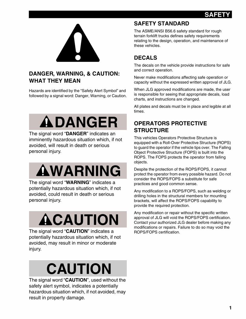
DANGER, WARNING, & CAUTION: WHAT THEY MEAN
Hazards are identified by the “Safety Alert Symbol” and followed by a signal word: Danger, Warning, or Caution.
DANGERThe signal word “DANGER” indicates an imminently hazardous situation which, if not avoided, will result in death or serious personal injury.
WARNINGThe signal word “WARNING” indicates a potentially hazardous situation which, if not avoided, could result in death or serious personal injury.
CAUTIONThe signal word “CAUTION” indicates a potentially hazardous situation which, if not avoided, may result in minor or moderate injury.
CAUTIONThe signal word “CAUTION”, used without the safety alert symbol, indicates a potentially hazardous situation which, if not avoided, may result in property damage.
SAFETY STANDARDThe ASME/ANSI B56.6 safety standard for rough terrain forklift trucks defines safety requirements relating to the design, operation, and maintenance of these vehicles.
DECALSThe decals on the vehicle provide instructions for safe and correct operation.
Never make modifications affecting safe operation or capacity without the expressed written approval of JLG.
When JLG approved modifications are made, the user is responsible for seeing that appropriate decals, load charts, and instructions are changed.
All plates and decals must be in place and legible at all times.
OPERATORS PROTECTIVE STRUCTUREThis vehicles Operators Protective Structure is equipped with a Roll-Over Protective Structure (ROPS) to guard the operator if the vehicle tips over. The Falling Object Protective Structure (FOPS) is built into the ROPS. The FOPS protects the operator from falling objects.
Despite the protection of the ROPS/FOPS, it cannot protect the operator from every possible hazard. Do not consider the ROPS/FOPS a substitute for safe practices and good common sense.
Any modification to a ROPS/FOPS, such as welding or drilling holes in the structural members for mounting brackets, will affect the ROPS/FOPS capability to provide the required protection.
Any modification or repair without the specific written approval of JLG will void the ROPS/FOPS certification. Contact your authorized JLG dealer before making any modifications or repairs. Failure to do so may void the ROPS/FOPS certification.
W1038
W
1
SAFETY
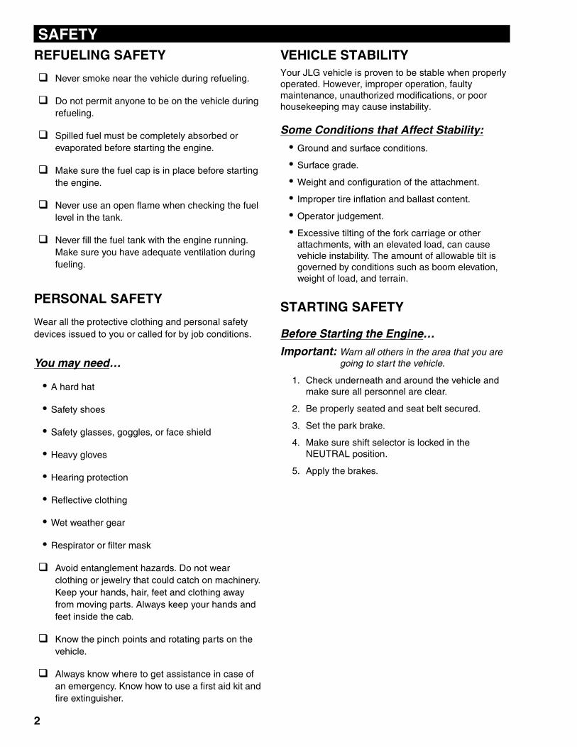
REFUELING SAFETYNever smoke near the vehicle during refueling.
Do not permit anyone to be on the vehicle during refueling.
Spilled fuel must be completely absorbed or evaporated before starting the engine.
Make sure the fuel cap is in place before starting the engine.
Never use an open flame when checking the fuel level in the tank.
Never fill the fuel tank with the engine running. Make sure you have adequate ventilation during fueling.
PERSONAL SAFETY
Wear all the protective clothing and personal safety devices issued to you or called for by job conditions.
You may need…
• A hard hat
• Safety shoes
• Safety glasses, goggles, or face shield
• Heavy gloves
• Hearing protection
• Reflective clothing
• Wet weather gear
• Respirator or filter mask
Avoid entanglement hazards. Do not wear clothing or jewelry that could catch on machinery. Keep your hands, hair, feet and clothing away from moving parts. Always keep your hands and feet inside the cab.
Know the pinch points and rotating parts on the vehicle.
Always know where to get assistance in case of an emergency. Know how to use a first aid kit and fire extinguisher.
VEHICLE STABILITYYour JLG vehicle is proven to be stable when properly operated. However, improper operation, faulty maintenance, unauthorized modifications, or poor housekeeping may cause instability.
Some Conditions that Affect Stability:
• Ground and surface conditions.
• Surface grade.
• Weight and configuration of the attachment.
• Improper tire inflation and ballast content.
• Operator judgement.
• Excessive tilting of the fork carriage or other attachments, with an elevated load, can cause vehicle instability. The amount of allowable tilt is governed by conditions such as boom elevation, weight of load, and terrain.
STARTING SAFETY
Before Starting the Engine…
Important: Warn all others in the area that you are going to start the vehicle.
1. Check underneath and around the vehicle and make sure all personnel are clear.
2. Be properly seated and seat belt secured.
3. Set the park brake.
4. Make sure shift selector is locked in the NEUTRAL position.
5. Apply the brakes.
2
SAFETY
OPERATION SAFETYSafe operation is the responsibility of the operator.
Improper use of the vehicle can lead to dangerous situations for yourself, those around you, the vehicle and the work area. You must have safe working habits and be aware of hazardous working conditions.
Thoroughly read and understand this entire manual. Follow all safety rules and practices explained in this manual.
The vehicle must be checked every day or at the start of each shift. See “Check the Equipment” on page 8.
To meet the requirements of different operating conditions, JLG offers optional lighting packages for your vehicle. Do not operate the vehicle if it is not equipped with lights when conditions require them. If your vehicle is not equipped with the proper lights, contact your authorized JLG dealer for available lighting packages.
If operating in an enclosed or partially enclosed environment, make sure there is enough ventilation. Engine exhaust fumes can be deadly to you and those around you if precautions are not taken. Questions about the air quality in the working environment and sampling methods should be directed to a qualified person.
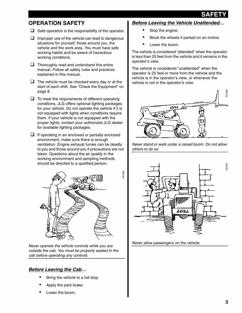
Never operate the vehicle controls while you are outside the cab. You must be properly seated in the cab before operating any controls.
Before Leaving the Cab…
• Bring the vehicle to a full stop.
• Apply the park brake.
• Lower the boom.
W10
08
Before Leaving the Vehicle Unattended…
• Stop the engine.
• Block the wheels if parked on an incline.
• Lower the boom.
The vehicle is considered “attended” when the operator is less than 25 feet from the vehicle and it remains in the operator’s view.
The vehicle is considered “unattended” when the operator is 25 feet or more from the vehicle and the vehicle is in the operator’s view, or whenever the vehicle is not in the operator’s view.
Never stand or walk under a raised boom. Do not allow others to do so.
Never allow passengers on the vehicle.
W10
09W
1007
3
SAFETY
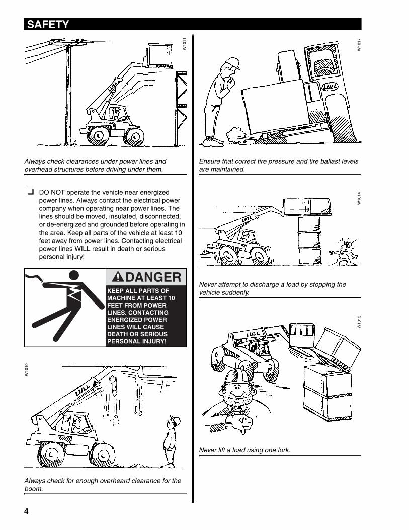
Always check clearances under power lines and overhead structures before driving under them.
DO NOT operate the vehicle near energized power lines. Always contact the electrical power company when operating near power lines. The lines should be moved, insulated, disconnected, or de-energized and grounded before operating in the area. Keep all parts of the vehicle at least 10 feet away from power lines. Contacting electrical power lines WILL result in death or serious personal injury!
Always check for enough overheard clearance for the boom.
Ensure that correct tire pressure and tire ballast levels are maintained.
Never attempt to discharge a load by stopping the vehicle suddenly.
Never lift a load using one fork.
W10
11
KEEP ALL PARTS OF MACHINE AT LEAST 10 FEET FROM POWER LINES. CONTACTING ENERGIZED POWER LINES WILL CAUSE DEATH OR SERIOUS PERSONAL INJURY!
DANGER
W10
10
W10
17W
1014
W10
13
4
SAFETY
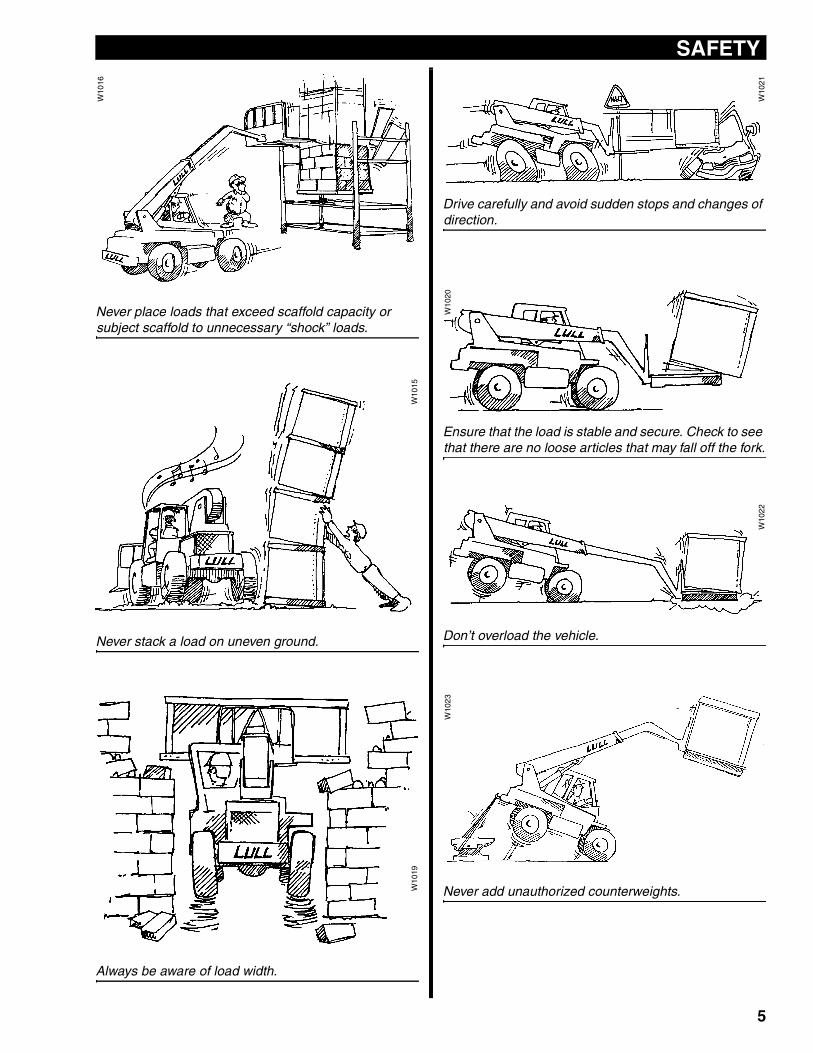
Never place loads that exceed scaffold capacity or subject scaffold to unnecessary “shock” loads.
Never stack a load on uneven ground.
Always be aware of load width.
W10
16
W10
15W
1019
Drive carefully and avoid sudden stops and changes of direction.
Ensure that the load is stable and secure. Check to see that there are no loose articles that may fall off the fork.
Don’t overload the vehicle.
Never add unauthorized counterweights.
W10
21
W10
20
W10
22
W10
23
5
SAFETY
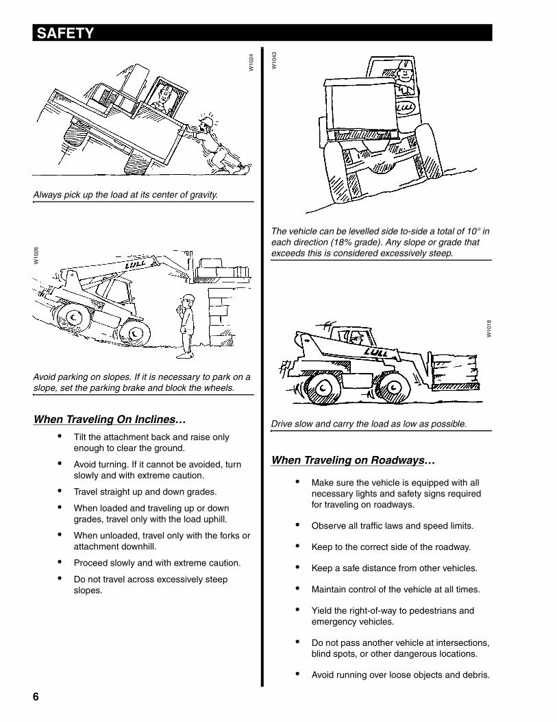
Always pick up the load at its center of gravity.
Avoid parking on slopes. If it is necessary to park on a slope, set the parking brake and block the wheels.
When Traveling On Inclines…
• Tilt the attachment back and raise only enough to clear the ground.
• Avoid turning. If it cannot be avoided, turn slowly and with extreme caution.
• Travel straight up and down grades.
• When loaded and traveling up or down grades, travel only with the load uphill.
• When unloaded, travel only with the forks or attachment downhill.
• Proceed slowly and with extreme caution.
• Do not travel across excessively steep slopes.
The vehicle can be levelled side to-side a total of 10° in each direction (18% grade). Any slope or grade that exceeds this is considered excessively steep.
Drive slow and carry the load as low as possible.
When Traveling on Roadways…
• Make sure the vehicle is equipped with all necessary lights and safety signs required for traveling on roadways.
• Observe all traffic laws and speed limits.
• Keep to the correct side of the roadway.
• Keep a safe distance from other vehicles.
• Maintain control of the vehicle at all times.
• Yield the right-of-way to pedestrians and emergency vehicles.
• Do not pass another vehicle at intersections, blind spots, or other dangerous locations.
• Avoid running over loose objects and debris.
W10
24
W10
26
W10
43
W10
18
6
SAFETY
Additional Safety Instructions:• Maneuver the vehicle carefully. Do not cause the load to shift or the vehicle to tip.
• Slow down for wet and slippery surfaces and changes in terrain.
• Turn the steering wheel smoothly and slow down when turning.
• Do not make sharp turns at high speeds.
• Take special care when traveling without a load. The vehicle is more susceptible to tipping over on its side.
• Do not continue to operate the vehicle if an unsafe condition is found. Stop the vehicle and report the condition to the designated authority.
• Never make repairs or adjustments unless you are authorized to do so.
• Always keep your hands and feet inside the cab.
• Never reach into the boom or attachments.
• Understand the limitations of the vehicle and drive safely.
• Watch for pedestrians, especially when backing up or turning and where pedestrians may step into the path of the vehicle.
• The vehicle may add to the overall sound level of the work area. Give consideration to the sound exposure of those working around you.
• If a fuel leak is found, do not operate the vehicle until the problem is fixed.
• When approaching areas where vision is obstructed, always slow down and sound the horn.
• Report all accidents involving personnel, building structures, and equipment to your supervisor or as directed.
• Use caution when operating on ramps, platforms, trenches, and other similar surfaces.
• Keep a clear view of the terrain and where the vehicle is heading. Watch out for other vehicles, people, and structures.
• Where the load will obstruct the operator's vision, it is recommended that the vehicle be operated in reverse, looking backwards in the direction of travel. Travel at a slower speed and get someone to direct you.
• Avoid excessively steep slopes or unstable surfaces. If you must drive on a slope, level the vehicle, keep the load low and proceed with extreme caution. Do not, under any circumstances, drive across excessively steep slopes.
• Do not block access to fire lanes or fire equipment.
• Do not jump! If a vehicle ever becomes unstable and starts to tip over: Brace yourself and stay with the vehicle, Keep your seat belt fastened, Hold on firmly and lean away from the point of impact.
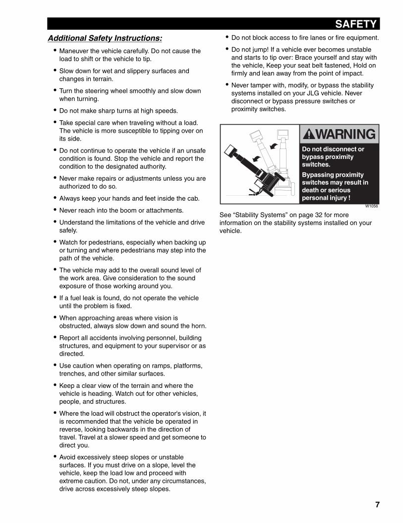
• Never tamper with, modify, or bypass the stability systems installed on your JLG vehicle. Never disconnect or bypass pressure switches or proximity switches.
See “Stability Systems” on page 32 for more information on the stability systems installed on your vehicle.
Do not disconnect or bypass proximity switches.
Bypassing proximity switches may result in death or serious personal injury !
W1056
7
BEFORE OPERATING THE MACHINE
CHECK THE EQUIPMENTNote: Before you begin your workday, take time to check ( ) your vehicle and have all systems in good operational condition.
Check the following:
Warning decals, special instructions, service/lubrication schedule and operators manuals. Make sure they are legible and stored in the proper location. NEVER operate without a legible load chart.Engine oil level. Add oil as required.Radiator coolant level. Add coolant as required.Hydraulic fluid level. Add hydraulic fluid as required.Hydraulic hoses and hose connections for wear or leaks. Repair or replace any damaged hoses or connections.Condition of boom chain system.Transmission oil cooler and engine radiator for dirty fins.Back-up alarm and horn.Structural and weld damage.Forks for welded repairs, cracks, wear and misalignment.
Tires for cuts, bulges, correct tire pressure and proper ballast content.Loose hardware.All wheel lugs.Service and park brakes for proper operation.All instruments, gauges and indicator lights.The steering, left and right.All control levers for proper operation.Keep engine and radiator clean and free of dirt and flammable material.The condition and operation of the seat belt and its mounts.Steps, pedals, and non-skid surfaces. Make sure they are clean and free of dirt, grease, oil, snow and ice.Placement and operation of doors, guards and covers.Cleanliness and operation of mirrors, window wipers and work lights.
Note: If there is any indication that faulty equipment exists, shutdown safely, inform the proper authority and DO NOT operate the vehicle until the problem has been fixed.
Remove or put away tools, lunch buckets, chains, hooks or any other loose objects that could interfere with operation.
KNOW THE WORK AREA
Learn as much as possible about the work area before operation. Walk around the worksite and inspect the terrain that you will be travelling on.
Make a note of surfaces to be avoided, including…
• Holes & Drop-offs.
• Obstacles.
• Soft mud & standing water.
• Oil spills & slippery surfaces.
Note: If any of the above conditions exist in the work area, correct the condition before operating. If the condition cannot be corrected, avoid operation in the problem area.
When operating on docks, ramps or floors, check for weak spots. Clear away trash and debris. Pick up anything that could puncture a tire. When required, check the vehicle's maximum fully loaded ground pressure weight if operating on a hollow floor system.
Watch for conditions that could cause…
• Loss of control.
• A collision.
• Tipover.
Check overhead clearances. Know the size of doorways and canopies. Know exactly how much clearance you have under power lines and telephone lines.
All local, state/provincial and federal regulations must be met before approaching power lines, overhead or underground cables or other power sources with any part of your vehicle. Do not operate the vehicle near energized power lines. Always contact the electrical power company when operating near power lines. The lines should be moved, insulated, disconnected, or de-energized and grounded before operating in the area. Keep all parts of the vehicle at least 10 feet away from power lines.
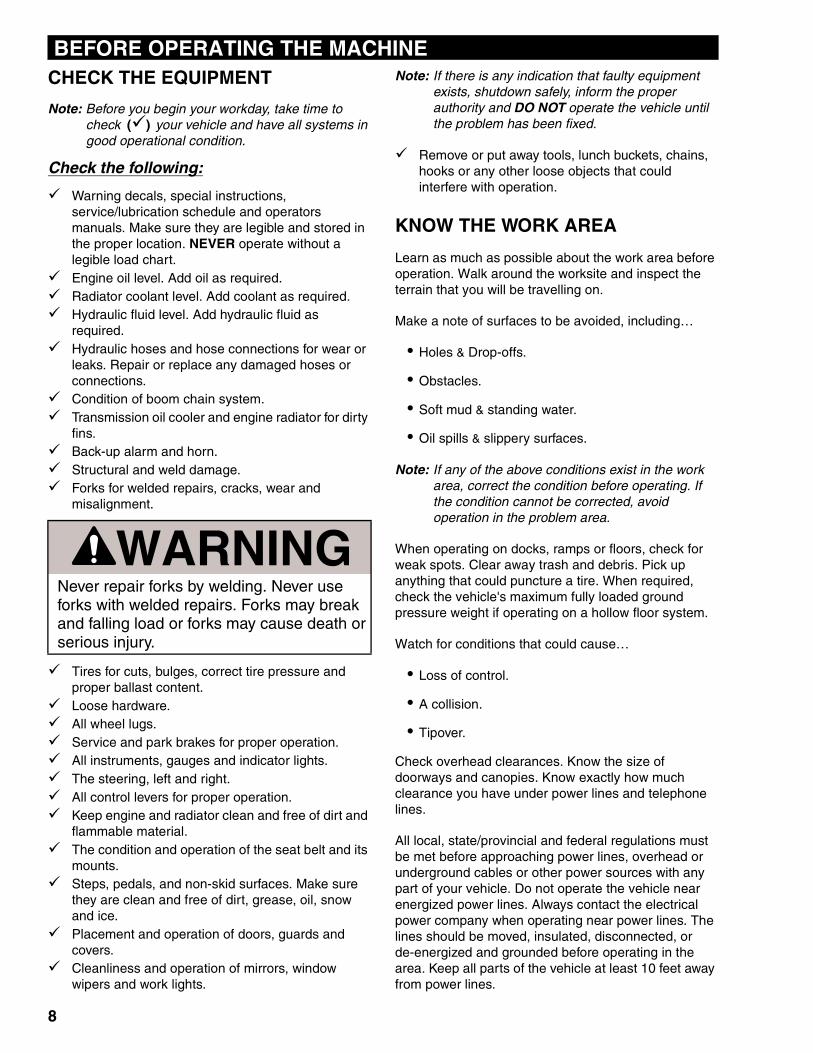
WARNINGNever repair forks by welding. Never use forks with welded repairs. Forks may break and falling load or forks may cause death or serious injury.
8
BEFORE OPERATING THE MACHINE
PLAN YOUR WORK
Before you operate, know how and where you will travel, turn and pickup, lift and place loads.
Choose a smooth level route to prevent possible tipover or loss of load.
If possible, avoid crossing…
• Ruts.
• Ditches.
• Curbs.
• Exposed railroad tracks.
Note: When these conditions cannot be avoided, keep the load as low as possible and travel very slowly and with extreme caution.
Know where there are any blind corner conditions on the worksite. Before turning a blind corner, stop, sound your horn, and proceed slowly.
Always maintain safe distances between your vehicle and other equipment that may be on the worksite.
Know the weights of all loads you may be expected to transport before attempting to lift them. Avoid loads of loose material if possible. Check that loads are properly banded or strapped together.
If you will be placing loads at high elevations, remember your depth perception is decreased because of distance. Use a signal person near the point where the load is to be landed.
Insure that adequate clearance is provided between both rear tail swing and front fork swing of the vehicle to avoid injury to personnel or damage to nearby equipment.
Know where you will be expected to park your vehicle at the end of the work day, preferably in a level area out of traffic. If the area is on a slope or incline, position the vehicle at right angles to the slope, set the parking brake, lower the boom to the ground, and block the wheels.
Remember…
• Be alert - know that conditions can change.
• Use common sense - show that you are a responsible operator.
• Be a defensive operator - prevent accidents before they happen.
SAFE VEHICLE OPERATION For safe operation of this vehicle you must be a qualified and authorized operator. To be qualified, you must understand the written instructions supplied by the manufacturer, have training (including actual operation of this vehicle) and know the safety rules and regulations for the jobsite.
An operator must not use drugs or alcohol which can affect his alertness and coordination. An operator on prescription or over-the-counter drugs needs medical approval to safely operate these vehicles.
KNOW THE RULES Most employers have rules governing proper operation and maintenance of equipment. Before you start work at a new location, check with your supervisor or the safety coordinator. Ask about rules you may be expected to obey.
Make sure you understand the rules covering traffic at your jobsite. Make sure you recognize and understand the meaning of all signs, flags, and markings. Make sure you understand all hand, flag, whistle, siren, or bell signals. Make sure you know when to use lights, turn signals, flashers and horn.
PROTECT YOURSELF Wear all the protective clothing and personal safety devices issued to you or called for by job conditions.
You may need:
• A hard hat.
• Safety shoes.
• Safety glasses, goggles, or face shield.
• Heavy gloves.
• Hearing protection.
• Reflective clothing.
• Wet weather gear.
• Respirator or filter mask.
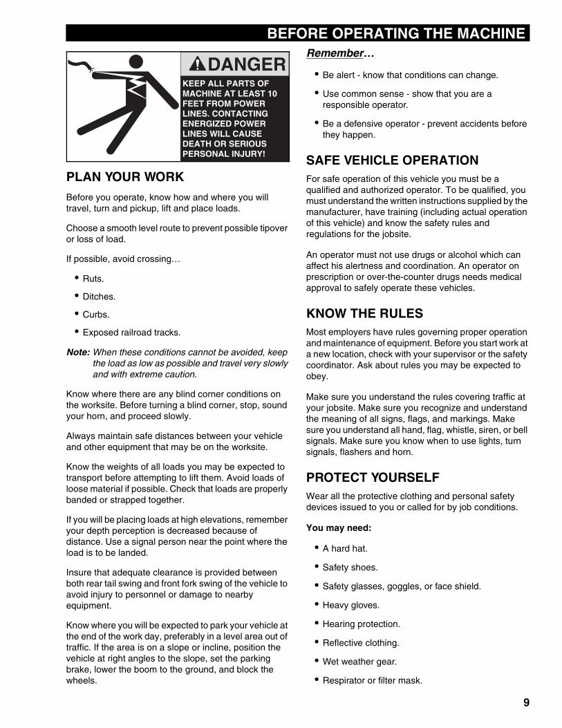
KEEP ALL PARTS OF MACHINE AT LEAST 10 FEET FROM POWER LINES. CONTACTING ENERGIZED POWER LINES WILL CAUSE DEATH OR SERIOUS PERSONAL INJURY!
DANGER
9
BEFORE OPERATING THE MACHINE
MOUNT AND DISMOUNT PROPERLYAlways use “Three Point Contact” when mounting or dismounting the vehicle. “Three Point Contact” means that three out of four arms and legs are in contact with the vehicle at all times during mount and dismount.Clean your shoes and wipe your hands before mounting vehicle. Always use hand-hold and step when mounting.
Never use control levers as a hand-hold when mounting or dismounting the vehicle. Never step on foot controls when mounting or dismounting the vehicle.
Never attempt to mount a moving vehicle.
10

BEFORE OPERATING THE MACHINE
11
INSTRUMENTS AND CONTROLS
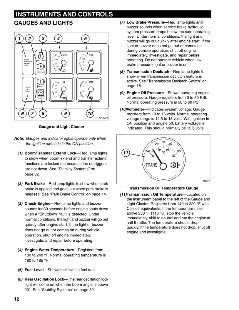
GAUGES AND LIGHTSGauge and Light Cluster
Note: Gauges and indicator lights operate only when the ignition switch is in the ON position.
(1) Boom/Transfer Extend Lock—Red lamp lights to show when boom extend and transfer extend functions are locked out because the outriggers are not down. See “Stability Systems” on page 32.
(2) Park Brake—Red lamp lights to show when park brake is applied and goes out when park brake is released. See “Park Brake Control” on page 14.
(3) Check Engine—Red lamp lights and buzzer sounds for 30 seconds before engine shuts down when a “Shutdown” fault is detected. Under normal conditions, the light and buzzer will go out quickly after engine start. If the light or buzzer does not go out or comes on during vehicle operation, shut off engine immediately, investigate, and repair before operating.
(4) Engine Water Temperature—Registers from 100 to 240 °F. Normal operating temperature is 180 to 185 °F.
(5) Fuel Level—Shows fuel level in fuel tank.
(6) Rear Oscillation Lock—The rear oscillation lock light will come on when the boom angle is above 20°. See “Stability Systems” on page 32.
(7) Low Brake Pressure—Red lamp lights and buzzer sounds when service brake hydraulic system pressure drops below the safe operating level. Under normal conditions, the light and buzzer will go out quickly after engine start. If the light or buzzer does not go out or comes on during vehicle operation, shut off engine immediately, investigate, and repair before operating. Do not operate vehicle when low brake pressure light or buzzer is on.
(8) Transmission Declutch—Red lamp lights to show when transmission declutch feature is active. See “Transmission Declutch Switch” on page 16.
(9) Engine Oil Pressure—Shows operating engine oil pressure. Gauge registers from 0 to 80 PSI. Normal operating pressure is 50 to 60 PSI.
(10)Voltmeter—Indicates system voltage. Gauge registers from 10 to 16 volts. Normal operating voltage range is 14.5 to 15 volts. With ignition in ON position and engine off, battery voltage is indicated. This should normally be 12.6 volts.
Transmission Oil Temperature Gauge
(11)Transmission Oil Temperature—Located on the instrument panel to the left of the Gauge and Light Cluster. Registers from 140 to 320 °F with Celsius equivalents. If the temperature rises above 230 °F (110 °C) stop the vehicle immediately, shift to neutral and run the engine at half throttle. The temperature should drop quickly. If the temperature does not drop, shut off engine and investigate.
���������������� ����
����������
�����
��������� �������
�����
����
������
������ ����
����
��
�����
��
��
��
��
�
���
� �����
������
����������
�
������������
7OV0030
4 5
6 8 9 10
1 2 3
140
240
138
60
TRANS
280
320
160
115
°F
°C11
H1057
12
INSTRUMENTS AND CONTROLS
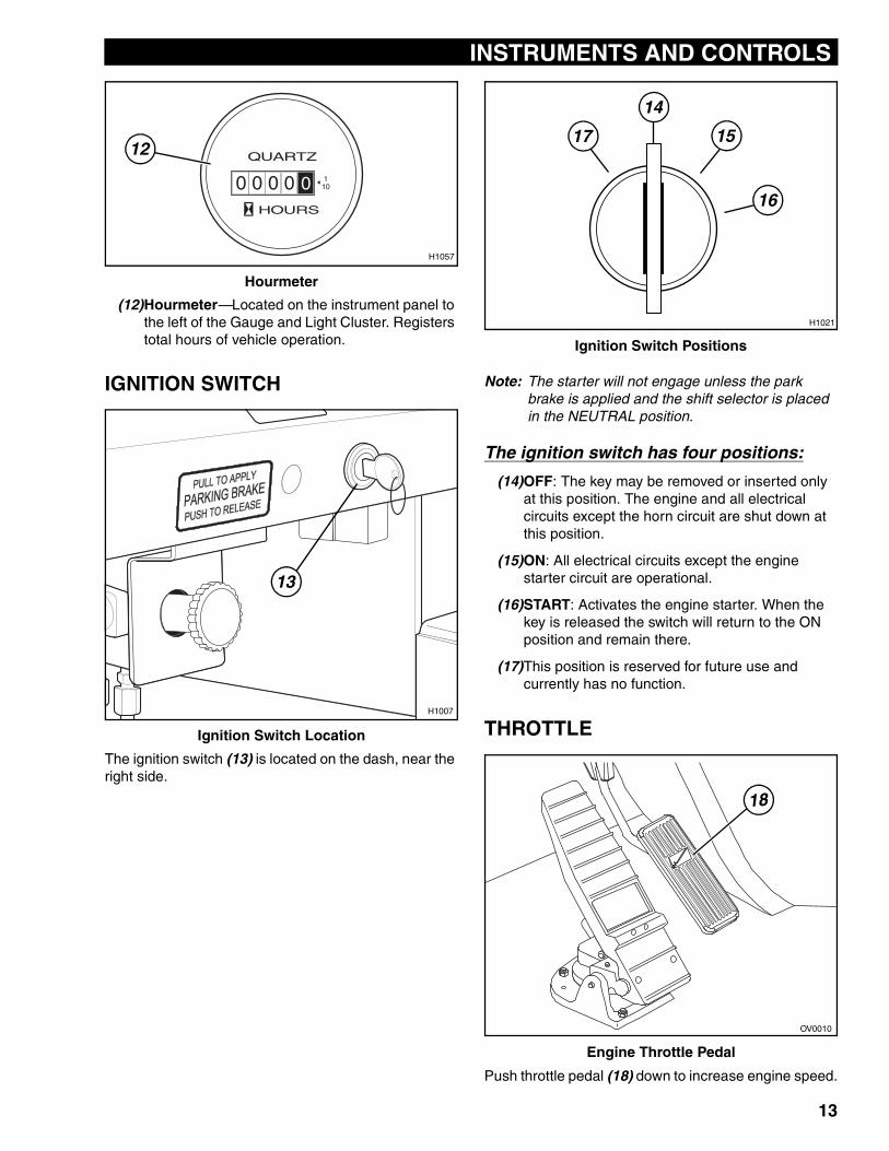
Hourmeter
(12)Hourmeter—Located on the instrument panel to the left of the Gauge and Light Cluster. Registers total hours of vehicle operation.
IGNITION SWITCH
Ignition Switch Location
The ignition switch (13) is located on the dash, near the right side.
Ignition Switch Positions
Note: The starter will not engage unless the park brake is applied and the shift selector is placed in the NEUTRAL position.
The ignition switch has four positions:
(14)OFF: The key may be removed or inserted only at this position. The engine and all electrical circuits except the horn circuit are shut down at this position.
(15)ON: All electrical circuits except the engine starter circuit are operational.
(16)START: Activates the engine starter. When the key is released the switch will return to the ON position and remain there.
(17)This position is reserved for future use and currently has no function.
THROTTLE
Engine Throttle Pedal
Push throttle pedal (18) down to increase engine speed.
0 0 0 0 0HOURS
110
QUARTZ12
H1057
13
H1007
H1021
14
17
16
15
OV0010
18
13
INSTRUMENTS AND CONTROLS
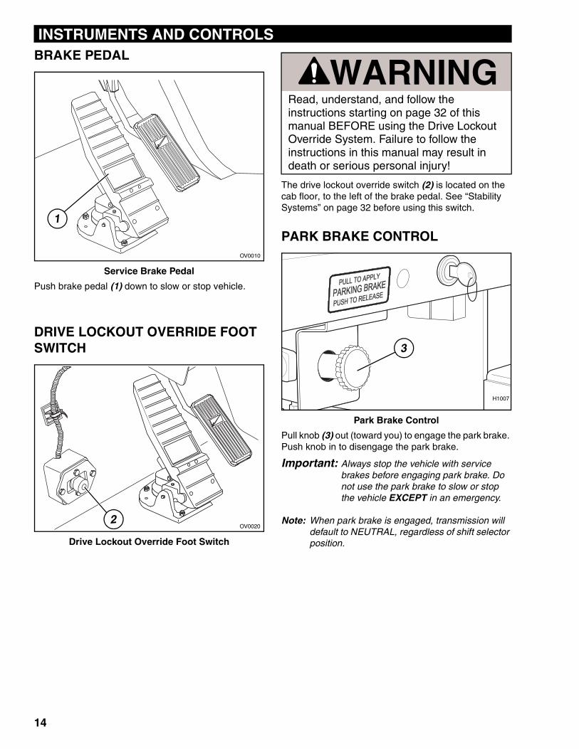
BRAKE PEDALService Brake Pedal
Push brake pedal (1) down to slow or stop vehicle.
DRIVE LOCKOUT OVERRIDE FOOT SWITCH
Drive Lockout Override Foot Switch
The drive lockout override switch (2) is located on the cab floor, to the left of the brake pedal. See “Stability Systems” on page 32 before using this switch.
PARK BRAKE CONTROL
Park Brake Control
Pull knob (3) out (toward you) to engage the park brake. Push knob in to disengage the park brake.
Important: Always stop the vehicle with service brakes before engaging park brake. Do not use the park brake to slow or stop the vehicle EXCEPT in an emergency.
Note: When park brake is engaged, transmission will default to NEUTRAL, regardless of shift selector position.
OV0010
1
OV00202
WARNINGRead, understand, and follow the instructions starting on page 32 of this manual BEFORE using the Drive Lockout Override System. Failure to follow the instructions in this manual may result in death or serious personal injury!
3
H1007
14
INSTRUMENTS AND CONTROLS
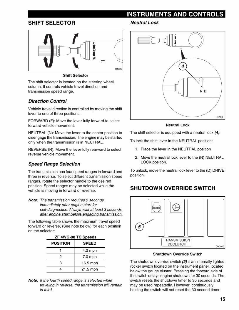
SHIFT SELECTORShift Selector
The shift selector is located on the steering wheel column. It controls vehicle travel direction and transmission speed range.
Direction Control
Vehicle travel direction is controlled by moving the shift lever to one of three positions:
FORWARD (F): Move the lever fully forward to select forward vehicle movement.
NEUTRAL (N): Move the lever to the center position to disengage the transmission. The engine may be started only when the transmission is in NEUTRAL.
REVERSE (R): Move the lever fully rearward to select reverse vehicle movement.
Speed Range Selection
The transmission has four speed ranges in forward and three in reverse. To select different transmission speed ranges, rotate the selector handle to the desired position. Speed ranges may be selected while the vehicle is moving in forward or reverse.
Note: The transmission requires 3 seconds immediately after engine start for self-diagnostics. Always wait at least 3 seconds after engine start before engaging transmission.
The following table shows the maximum travel speed forward or reverse, (See note below) for each position on the selector:
Note: If the fourth speed range is selected while traveling in reverse, the transmission will remain in third.
Neutral Lock
Neutral Lock
The shift selector is equipped with a neutral lock (4).
To lock the shift lever in the NEUTRAL position:
1. Place the lever in the NEUTRAL position
2. Move the neutral lock lever to the (N) NEUTRAL LOCK position.
To unlock, move the neutral lock lever to the (D) DRIVE position.
SHUTDOWN OVERRIDE SWITCH
Shutdown Override Switch
The shutdown override switch (5) is an internally lighted rocker switch located on the instrument panel, located below the gauge cluster. Pressing the forward side of the switch delays engine shutdown for 30 seconds. The switch resets the shutdown timer to 30 seconds and may be used repeatedly. However, continuously holding the switch will not reset the 30 second timer.
ZF 4WG-98 TC Speeds
POSITION SPEED
1 4.2 mph
2 7.0 mph
3 16.5 mph
4 21.5 mph
F
N
R
1234
H1022
N D
F
N
R
1234
H1023
4
��������������� ��
OV0040
5
15
INSTRUMENTS AND CONTROLS
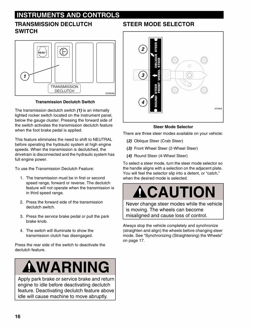
TRANSMISSION DECLUTCH SWITCHTransmission Declutch Switch
The transmission declutch switch (1) is an internally lighted rocker switch located on the instrument panel, below the gauge cluster. Pressing the forward side of the switch activates the transmission declutch feature when the foot brake pedal is applied.
This feature eliminates the need to shift to NEUTRAL before operating the hydraulic system at high engine speeds. When the transmission is declutched, the drivetrain is disconnected and the hydraulic system has full engine power.
To use the Transmission Declutch Feature:
1. The transmission must be in first or second speed range, forward or reverse. The declutch feature will not operate when the transmission is in third speed range.
2. Press the forward side of the transmission declutch switch.
3. Press the service brake pedal or pull the park brake knob.
4. The switch will illuminate to show the transmission clutch has disengaged.
Press the rear side of the switch to deactivate the declutch feature.
STEER MODE SELECTOR
Steer Mode Selector
There are three steer modes available on your vehicle:
(2) Oblique Steer (Crab Steer)
(3) Front Wheel Steer (2-Wheel Steer)
(4) Round Steer (4-Wheel Steer)
To select a steer mode, turn the steer mode selector so the handle aligns with a selection on the adjacent plate. You will feel the selector slip into a detent, or “catch,” when the desired mode is selected.
Always stop the vehicle completely and synchronize (straighten and align) the wheels before changing steer mode. See “Synchronizing (Straightening) the Wheels” on page 17.
WARNINGApply park brake or service brake and return engine to idle before deactivating declutch feature. Deactivating declutch feature above idle will cause machine to move abruptly.
��������������� ��
OV0040
1
CAUTIONNever change steer modes while the vehicle is moving. The wheels can become misaligned and cause loss of control.
FRO
NT
WH
EE
L S
TE
ER
RO
UN
D S
TE
ER
OB
LIQ
UE
ST
EE
R
H1044
4
2
3
16
INSTRUMENTS AND CONTROLS
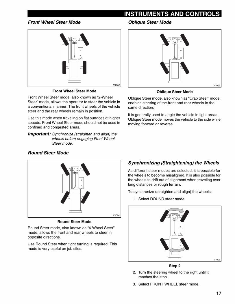
Front Wheel Steer ModeFront Wheel Steer Mode
Front Wheel Steer mode, also known as “2-Wheel Steer” mode, allows the operator to steer the vehicle in a conventional manner. The front wheels of the vehicle steer and the rear wheels remain in position.
Use this mode when traveling on flat surfaces at higher speeds. Front Wheel Steer mode should not be used in confined and congested areas.
Important: Synchronize (straighten and align) the wheels before engaging Front Wheel Steer mode.
Round Steer Mode
Round Steer Mode
Round Steer mode, also known as “4-Wheel Steer” mode, allows the front and rear wheels to steer in opposite directions.
Use Round Steer when tight turning is required. This mode is very useful on job sites.
Oblique Steer Mode
Oblique Steer Mode
Oblique Steer mode, also known as “Crab Steer” mode, enables steering of the front and rear wheels in the same direction.
It is generally used to angle the vehicle in tight areas. Oblique Steer mode moves the vehicle to the side while moving forward or reverse.
Synchronizing (Straightening) the Wheels
As different steer modes are selected, it is possible for the wheels to become misaligned. It is also possible for the wheels to drift out of alignment when traveling over long distances or rough terrain.
To synchronize (straighten and align) the wheels:
1. Select ROUND steer mode.
Step 2
2. Turn the steering wheel to the right until it reaches the stop.
3. Select FRONT WHEEL steer mode.
V1002
V1004
V1003
V1009
17
INSTRUMENTS AND CONTROLS
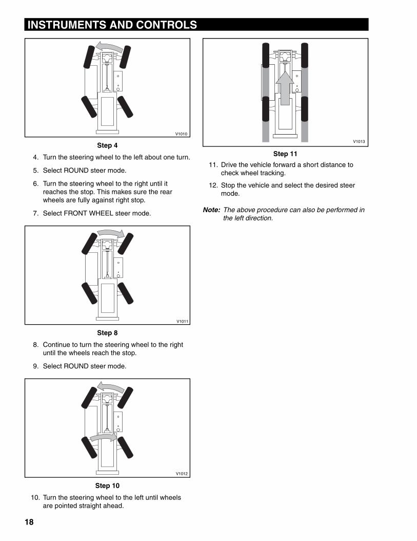
Step 4
4. Turn the steering wheel to the left about one turn.
5. Select ROUND steer mode.
6. Turn the steering wheel to the right until it reaches the stop. This makes sure the rear wheels are fully against right stop.
7. Select FRONT WHEEL steer mode.
Step 8
8. Continue to turn the steering wheel to the right until the wheels reach the stop.
9. Select ROUND steer mode.
Step 10
10. Turn the steering wheel to the left until wheels are pointed straight ahead.
Step 11
11. Drive the vehicle forward a short distance to check wheel tracking.
12. Stop the vehicle and select the desired steer mode.
Note: The above procedure can also be performed in the left direction.
V1010
V1011
V1012
V1013
18
INSTRUMENTS AND CONTROLS
JOYSTICK CONTROLSGeneral Description
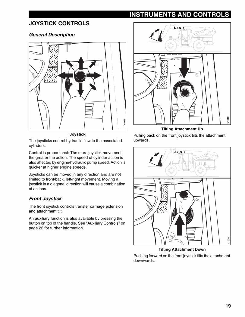
Joystick
The joysticks control hydraulic flow to the associated cylinders.
Control is proportional: The more joystick movement, the greater the action. The speed of cylinder action is also affected by engine/hydraulic pump speed. Action is quicker at higher engine speeds.
Joysticks can be moved in any direction and are not limited to front/back, left/right movement. Moving a joystick in a diagonal direction will cause a combination of actions.
Front Joystick
The front joystick controls transfer carriage extension and attachment tilt.
An auxiliary function is also available by pressing the button on top of the handle. See “Auxiliary Controls” on page 22 for further information.
Tilting Attachment Up
Pulling back on the front joystick tilts the attachment upwards.
Tilting Attachment Down
Pushing forward on the front joystick tilts the attachment downwards.
V10
18
V10
19V
1020
19
INSTRUMENTS AND CONTROLS
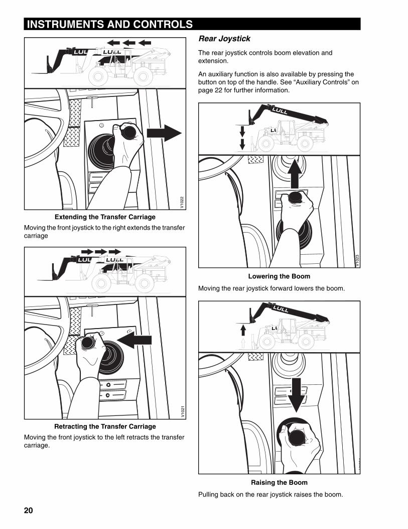
Extending the Transfer Carriage
Moving the front joystick to the right extends the transfer carriage
Retracting the Transfer Carriage
Moving the front joystick to the left retracts the transfer carriage.
Rear Joystick
The rear joystick controls boom elevation and extension.
An auxiliary function is also available by pressing the button on top of the handle. See “Auxiliary Controls” on page 22 for further information.
Lowering the Boom
Moving the rear joystick forward lowers the boom.
Raising the Boom
Pulling back on the rear joystick raises the boom.
V10
22V
1021
V10
23V
1024
20
INSTRUMENTS AND CONTROLS
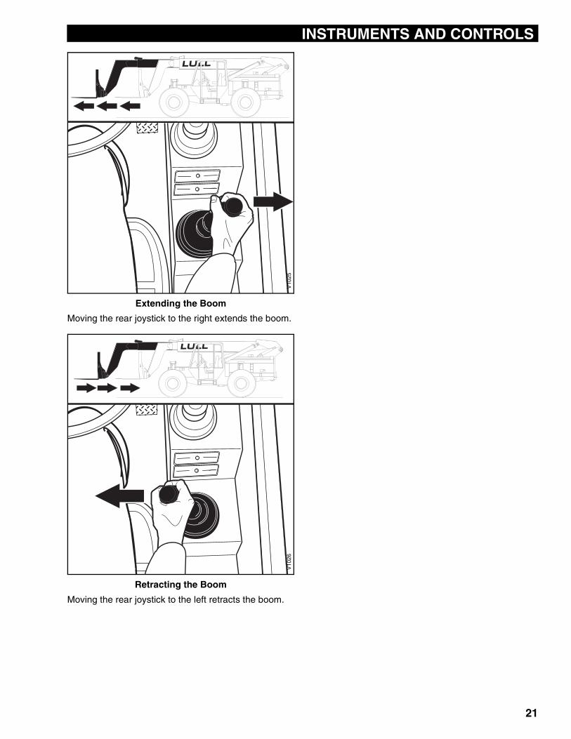
Extending the Boom
Moving the rear joystick to the right extends the boom.
Retracting the Boom
Moving the rear joystick to the left retracts the boom.
V10
25V
1026
21
INSTRUMENTS AND CONTROLS
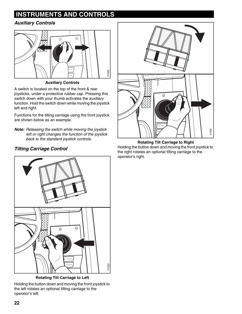
Auxiliary ControlsAuxiliary Controls
A switch is located on the top of the front & rear joysticks, under a protective rubber cap. Pressing this switch down with your thumb activates the auxiliary function. Hold the switch down while moving the joystick left and right.
Functions for the tilting carriage using the front joystick are shown below as an example.
Note: Releasing the switch while moving the joystick left or right changes the function of the joystick back to the standard joystick controls.
Tilting Carriage Control
Rotating Tilt Carriage to Left
Holding the button down and moving the front joystick to the left rotates an optional tilting carriage to the operator’s left.
Rotating Tilt Carriage to RightHolding the button down and moving the front joystick to the right rotates an optional tilting carriage to the operator’s right.
V10
32V
1033
V10
34
22
INSTRUMENTS AND CONTROLS
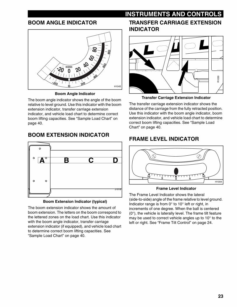
BOOM ANGLE INDICATORBoom Angle Indicator
The boom angle indicator shows the angle of the boom relative to level ground. Use this indicator with the boom extension indicator, transfer carriage extension indicator, and vehicle load chart to determine correct boom lifting capacities. See “Sample Load Chart” on page 40.
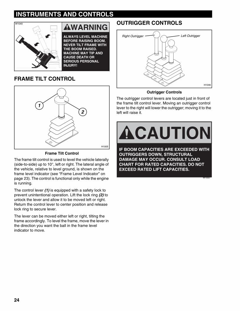
BOOM EXTENSION INDICATOR
Boom Extension Indicator (typical)
The boom extension indicator shows the amount of boom extension. The letters on the boom correspond to the lettered zones on the load chart. Use this indicator with the boom angle indicator, transfer carriage extension indicator (if equipped), and vehicle load chart to determine correct boom lifting capacities. See “Sample Load Chart” on page 40.
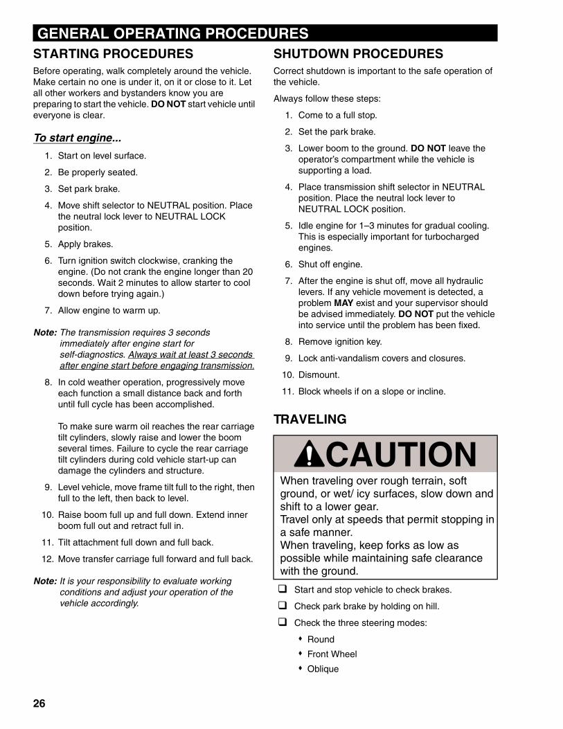
TRANSFER CARRIAGE EXTENSION INDICATOR
Transfer Carriage Extension Indicator
The transfer carriage extension indicator shows the distance of the carriage from the fully retracted position. Use this indicator with the boom angle indicator, boom extension indicator, and vehicle load chart to determine correct boom lifting capacities. See “Sample Load Chart” on page 40.
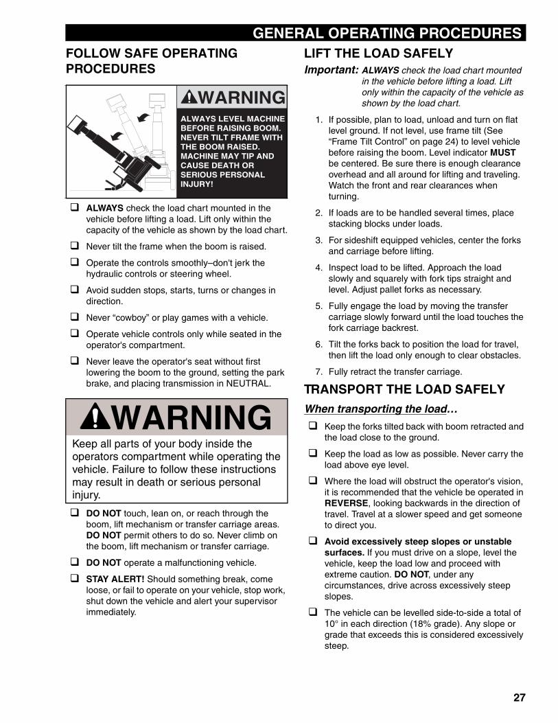
FRAME LEVEL INDICATOR
Frame Level Indicator
The Frame Level Indicator shows the lateral (side-to-side) angle of the frame relative to level ground. Indicator range is from 0° to 10° left or right, in increments of one degree. When the ball is centered (0°), the vehicle is laterally level. The frame tilt feature may be used to correct vehicle angles up to 10° to the left or right. See “Frame Tilt Control” on page 24.
-20 040
20
6080
-200 20
40
60
80
DEGREES
H1045
J1018
R10
30
0510
510
H1004
23
INSTRUMENTS AND CONTROLS
FRAME TILT CONTROL
Frame Tilt Control
The frame tilt control is used to level the vehicle laterally (side-to-side) up to 10°, left or right. The lateral angle of the vehicle, relative to level ground, is shown on the frame level indicator (see “Frame Level Indicator” on page 23). The control is functional only while the engine is running.
The control lever (1) is equipped with a safety lock to prevent unintentional operation. Lift the lock ring (2) to unlock the lever and allow it to be moved left or right. Return the control lever to center position and release lock ring to secure lever.
The lever can be moved either left or right, tilting the frame accordingly. To level the frame, move the lever in the direction you want the ball in the frame level indicator to move.
OUTRIGGER CONTROLS
Outrigger Controls
The outrigger control levers are located just in front of the frame tilt control lever. Moving an outrigger control lever to the right will lower the outrigger; moving it to the left will raise it.
WARNINGALWAYS LEVEL MACHINE BEFORE RAISING BOOM. NEVER TILT FRAME WITH THE BOOM RAISED. MACHINE MAY TIP AND CAUSE DEATH OR SERIOUS PERSONAL INJURY!
W1040
H1005
21
Left OutriggerRight Outrigger
H1046
CAUTIONIF BOOM CAPACITIES ARE EXCEEDED WITH OUTRIGGERS DOWN, STRUCTURAL DAMAGE MAY OCCUR. CONSULT LOAD CHART FOR RATED CAPACITIES. DO NOT EXCEED RATED LIFT CAPACITIES.
W1057
24

INSTRUMENTS AND CONTROLS
25
GENERAL OPERATING PROCEDURES
STARTING PROCEDURESBefore operating, walk completely around the vehicle. Make certain no one is under it, on it or close to it. Let all other workers and bystanders know you are preparing to start the vehicle. DO NOT start vehicle until everyone is clear.To start engine...
1. Start on level surface.
2. Be properly seated.
3. Set park brake.
4. Move shift selector to NEUTRAL position. Place the neutral lock lever to NEUTRAL LOCK position.
5. Apply brakes.
6. Turn ignition switch clockwise, cranking the engine. (Do not crank the engine longer than 20 seconds. Wait 2 minutes to allow starter to cool down before trying again.)
7. Allow engine to warm up.
Note: The transmission requires 3 seconds immediately after engine start for self-diagnostics. Always wait at least 3 seconds after engine start before engaging transmission.
8. In cold weather operation, progressively move each function a small distance back and forth until full cycle has been accomplished.
To make sure warm oil reaches the rear carriage tilt cylinders, slowly raise and lower the boom several times. Failure to cycle the rear carriage tilt cylinders during cold vehicle start-up can damage the cylinders and structure.
9. Level vehicle, move frame tilt full to the right, then full to the left, then back to level.
10. Raise boom full up and full down. Extend inner boom full out and retract full in.
11. Tilt attachment full down and full back.
12. Move transfer carriage full forward and full back.
Note: It is your responsibility to evaluate working conditions and adjust your operation of the vehicle accordingly.
SHUTDOWN PROCEDURESCorrect shutdown is important to the safe operation of the vehicle.
Always follow these steps:
1. Come to a full stop.
2. Set the park brake.
3. Lower boom to the ground. DO NOT leave the operator’s compartment while the vehicle is supporting a load.
4. Place transmission shift selector in NEUTRAL position. Place the neutral lock lever to NEUTRAL LOCK position.
5. Idle engine for 1–3 minutes for gradual cooling. This is especially important for turbocharged engines.
6. Shut off engine.
7. After the engine is shut off, move all hydraulic levers. If any vehicle movement is detected, a problem MAY exist and your supervisor should be advised immediately. DO NOT put the vehicle into service until the problem has been fixed.
8. Remove ignition key.
9. Lock anti-vandalism covers and closures.
10. Dismount.
11. Block wheels if on a slope or incline.
TRAVELING
Start and stop vehicle to check brakes.
Check park brake by holding on hill.
Check the three steering modes:
Round
Front Wheel
Oblique
CAUTIONWhen traveling over rough terrain, soft ground, or wet/ icy surfaces, slow down and shift to a lower gear.Travel only at speeds that permit stopping in a safe manner.When traveling, keep forks as low as possible while maintaining safe clearance with the ground.
26
GENERAL OPERATING PROCEDURES
FOLLOW SAFE OPERATING PROCEDURESALWAYS check the load chart mounted in the vehicle before lifting a load. Lift only within the capacity of the vehicle as shown by the load chart.
Never tilt the frame when the boom is raised.
Operate the controls smoothly–don't jerk the hydraulic controls or steering wheel.
Avoid sudden stops, starts, turns or changes in direction.
Never “cowboy” or play games with a vehicle.
Operate vehicle controls only while seated in the operator's compartment.
Never leave the operator's seat without first lowering the boom to the ground, setting the park brake, and placing transmission in NEUTRAL.
DO NOT touch, lean on, or reach through the boom, lift mechanism or transfer carriage areas. DO NOT permit others to do so. Never climb on the boom, lift mechanism or transfer carriage.
DO NOT operate a malfunctioning vehicle.
STAY ALERT! Should something break, come loose, or fail to operate on your vehicle, stop work, shut down the vehicle and alert your supervisor immediately.
LIFT THE LOAD SAFELYImportant: ALWAYS check the load chart mounted
in the vehicle before lifting a load. Lift only within the capacity of the vehicle as shown by the load chart.
1. If possible, plan to load, unload and turn on flat level ground. If not level, use frame tilt (See “Frame Tilt Control” on page 24) to level vehicle before raising the boom. Level indicator MUST be centered. Be sure there is enough clearance overhead and all around for lifting and traveling. Watch the front and rear clearances when turning.
2. If loads are to be handled several times, place stacking blocks under loads.
3. For sideshift equipped vehicles, center the forks and carriage before lifting.
4. Inspect load to be lifted. Approach the load slowly and squarely with fork tips straight and level. Adjust pallet forks as necessary.
5. Fully engage the load by moving the transfer carriage slowly forward until the load touches the fork carriage backrest.
6. Tilt the forks back to position the load for travel, then lift the load only enough to clear obstacles.
7. Fully retract the transfer carriage.
TRANSPORT THE LOAD SAFELY
When transporting the load…
Keep the forks tilted back with boom retracted and the load close to the ground.
Keep the load as low as possible. Never carry the load above eye level.
Where the load will obstruct the operator's vision, it is recommended that the vehicle be operated in REVERSE, looking backwards in the direction of travel. Travel at a slower speed and get someone to direct you.
Avoid excessively steep slopes or unstable surfaces. If you must drive on a slope, level the vehicle, keep the load low and proceed with extreme caution. DO NOT, under any circumstances, drive across excessively steep slopes.
The vehicle can be levelled side-to-side a total of 10° in each direction (18% grade). Any slope or grade that exceeds this is considered excessively steep.
WARNINGKeep all parts of your body inside the operators compartment while operating the vehicle. Failure to follow these instructions may result in death or serious personal injury.
WARNINGALWAYS LEVEL MACHINE BEFORE RAISING BOOM. NEVER TILT FRAME WITH THE BOOM RAISED. MACHINE MAY TIP AND CAUSE DEATH OR SERIOUS PERSONAL INJURY!
27
GENERAL OPERATING PROCEDURES
If a slope is too steep to allow the frame to be leveled, do not raise the boom. The frame must always be level before raising the boom.Reduce speed and sound horn at blind intersections, exits and when approaching pedestrians.
Slow down for turns, ramps, dips, uneven or slippery surfaces and in congested areas.
Avoid driving over loose objects and holes in roadway surfaces to prevent losing the load or tipping the vehicle.
Avoid crossing ditches, curbs or exposed railroad tracks. If crossing cannot be avoided, keep the load as low as possible, travel very slowly, and proceed with caution.
Avoid panic braking. Apply brakes smoothly for a controlled stop to prevent toppling the load.
SAFELY PLACING THE LOAD
Elevated or Overhead Placement
Important: When stacking or placing a load to a high landing use extreme caution! There may be other workers in the immediate area you cannot see. Make sure that all bystanders are away from the area where the load could tip or fall.
1. Be sure the landing point can safely support the weight of the load. The chosen landing location should be level, both front-to-back and side-to-side.
You should know or be able to estimate the weight and load center of the load that you will be lifting. If you are unsure of the weight and load center of the load, check with your supervisor or with the supplier of the material. ALWAYS check the load chart mounted in the vehicle before lifting a load. Lift only within the capacity of the vehicle as shown by the load chart.
2. Drive as close as possible to the landing location. Approach very slowly with the load as low as possible.
3. Tilt carriage rearward to cradle the load.
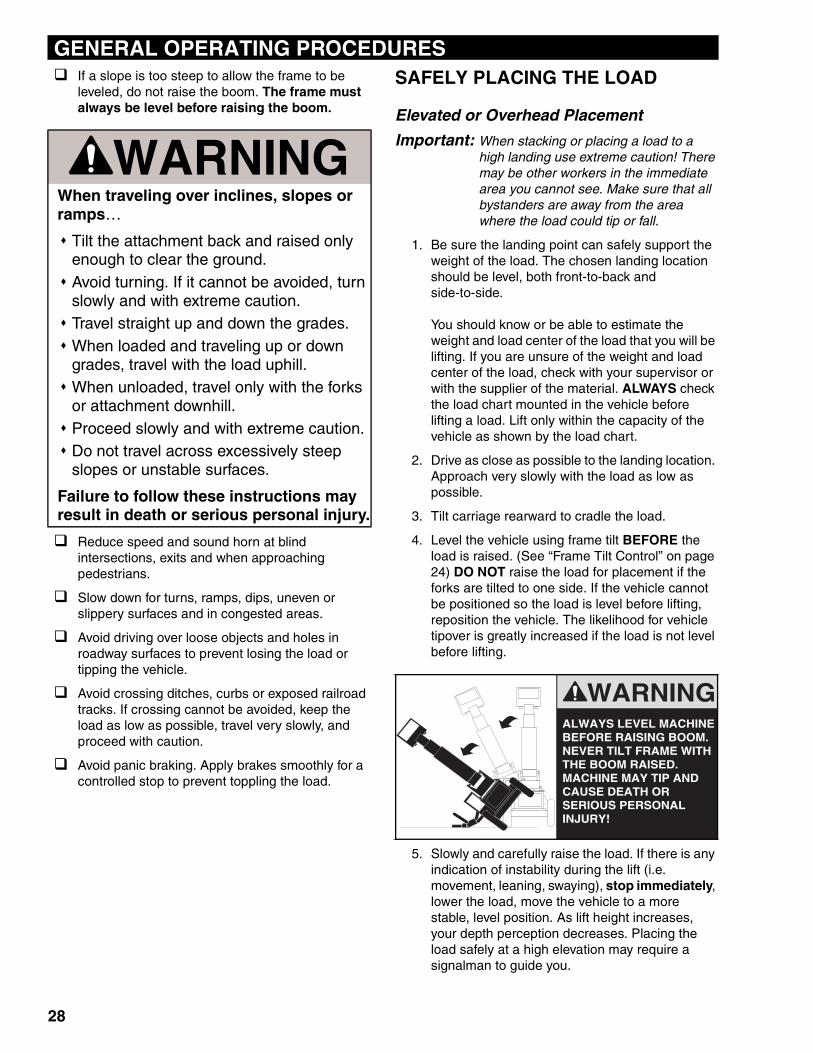
4. Level the vehicle using frame tilt BEFORE the load is raised. (See “Frame Tilt Control” on page 24) DO NOT raise the load for placement if the forks are tilted to one side. If the vehicle cannot be positioned so the load is level before lifting, reposition the vehicle. The likelihood for vehicle tipover is greatly increased if the load is not level before lifting.
5. Slowly and carefully raise the load. If there is any indication of instability during the lift (i.e. movement, leaning, swaying), stop immediately, lower the load, move the vehicle to a more stable, level position. As lift height increases, your depth perception decreases. Placing the load safely at a high elevation may require a signalman to guide you.
WARNINGWhen traveling over inclines, slopes or ramps…
Tilt the attachment back and raised only enough to clear the ground.Avoid turning. If it cannot be avoided, turn slowly and with extreme caution.Travel straight up and down the grades. When loaded and traveling up or down grades, travel with the load uphill.When unloaded, travel only with the forks or attachment downhill.Proceed slowly and with extreme caution.Do not travel across excessively steep slopes or unstable surfaces.
Failure to follow these instructions may result in death or serious personal injury.
WARNINGALWAYS LEVEL MACHINE BEFORE RAISING BOOM. NEVER TILT FRAME WITH THE BOOM RAISED. MACHINE MAY TIP AND CAUSE DEATH OR SERIOUS PERSONAL INJURY!
28
GENERAL OPERATING PROCEDURES
6. When the load is slightly higher than the landingpoint, SLOWLY stop the lift..
7. Use the transfer carriage to place the load directly over the landing point. The transfer carriage allows safe and easy placement of the load without moving the vehicle. (Consult load charts for transfer capacity.) Forks should be level and parallel to the landing surface so that they may be easily retracted from under the load. Before retracting the forks, check landing point for any excessive bowing, cracking noises or other indications of overloading. If there is any indication that the landing surface cannot handle the weight of the load, place the load at a different location that you know can handle the weight. If the landing surface cannot handle the weight of the load, pick the load back up, lower it to the ground and lift a lighter load.
8. Lower the load slowly to place it and relieve the weight from the forks. Retract the transfer carriage until the forks are clear of the load. Lower and retract the boom BEFORE moving the vehicle.
9. The vehicle can now be moved from the landing location to continue work.
LIFTING PERSONNELJLG strongly recommends that you DO NOT use the JLG vehicle as a personnel lift. It is designed for material handling ONLY. If personnel MUST be lifted, lift only in accordance with ASME/ANSI B56.6 1992 (or later), Para. 5.15 and with a properly designed work platform.
WARNINGDo not ram the hydraulic lift cylinder to the end of its stroke. The jolt could spill the load resulting in death or serious personal injury.
29
GENERAL OPERATING PROCEDURES
QUICK ATTACHDisconnecting an Attachment
1. Come to a complete stop on flat, level ground.
2. Set the park brake.
3. Raise the boom so attachment clears ground.
4. Extend the boom a short distance.
5. Lower the boom to rest the attachment on level ground.
6. Shut off engine.
7. Disconnect attachment hydraulic lines (if equipped).
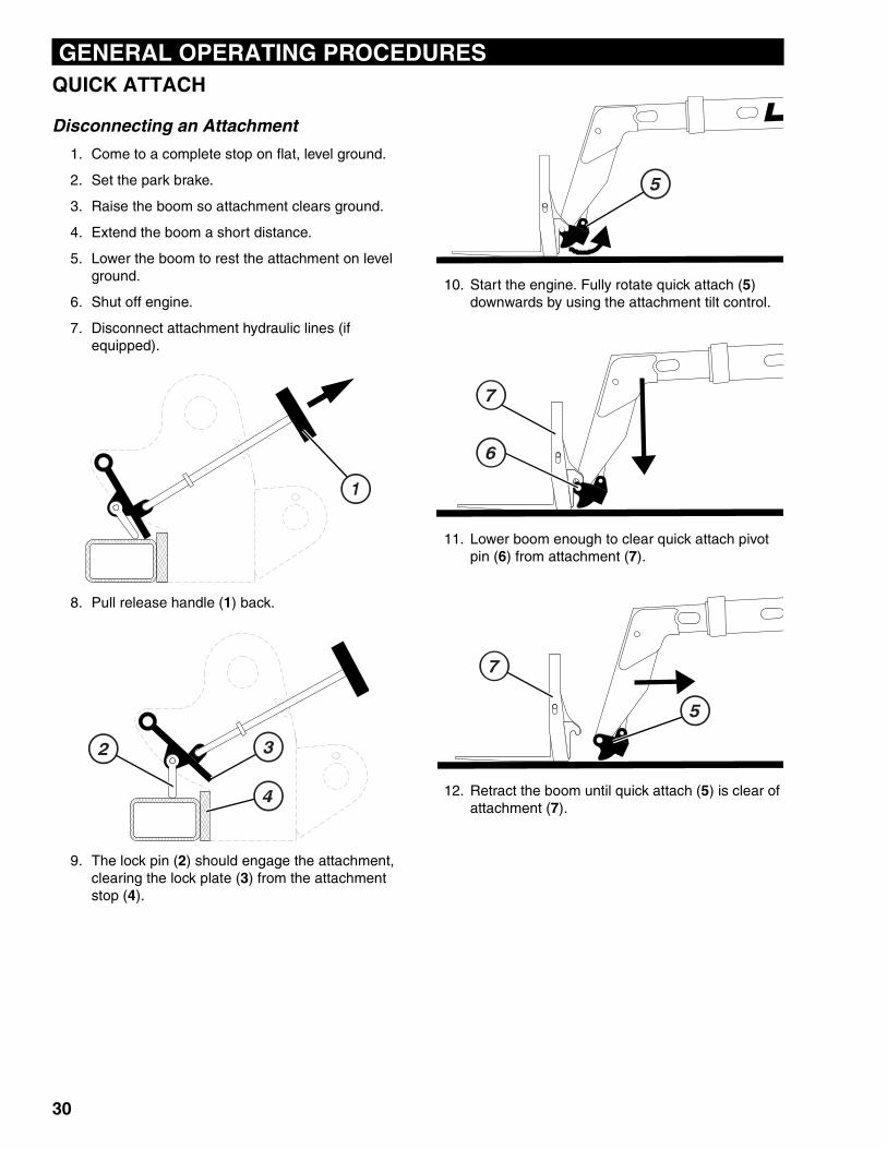
8. Pull release handle (1) back.
9. The lock pin (2) should engage the attachment, clearing the lock plate (3) from the attachment stop (4).
10. Start the engine. Fully rotate quick attach (5) downwards by using the attachment tilt control.
11. Lower boom enough to clear quick attach pivot pin (6) from attachment (7).
12. Retract the boom until quick attach (5) is clear of attachment (7).
30
GENERAL OPERATING PROCEDURES
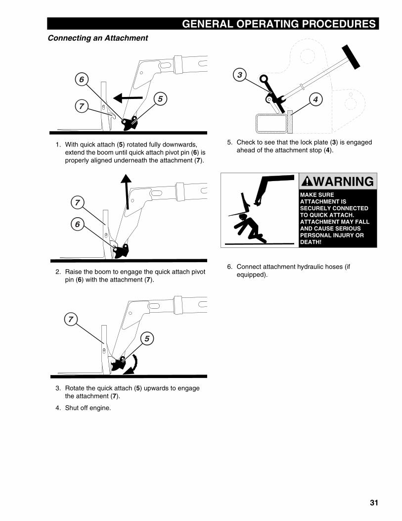
Connecting an Attachment1. With quick attach (5) rotated fully downwards, extend the boom until quick attach pivot pin (6) is properly aligned underneath the attachment (7).
2. Raise the boom to engage the quick attach pivot pin (6) with the attachment (7).
3. Rotate the quick attach (5) upwards to engage the attachment (7).
4. Shut off engine.
5. Check to see that the lock plate (3) is engaged ahead of the attachment stop (4).
6. Connect attachment hydraulic hoses (if equipped).
MAKE SURE ATTACHMENT IS SECURELY CONNECTED TO QUICK ATTACH.ATTACHMENT MAY FALL AND CAUSE SERIOUS PERSONAL INJURY OR DEATH!
WARNING
31
STABILITY SYSTEMS
SYSTEM SAFETYNever tamper with, modify, or bypass the stability systems installed on your JLG vehicle. Never disconnect or bypass pressure switches or proximity switches.REAR OSCILLATION LOCK SYSTEMThe Rear Oscillation Lock System prevents the frame from rotating on the rear axle.
System operation:
• With the boom below 20° elevation, the rear axle oscillates freely.
• With the boom between 20° and 40° elevation:Transmission is limited to first or second gear.Rear axle is in “restricted oscillation” mode.Frame tilt function still operates, but at a reduced speed when the boom elevation is above 20°.
• With the boom above 40° elevation:Transmission is locked out and rear axle oscillation is locked to the frame.Frame tilt function still operates, but at a reduced speed.
• With the boom above 40° elevation and the drive lockout override switch (page 14) pressed down:Transmission is limited to first gear.Rear axle is in “very restricted oscillation” mode.
• Fully pressing the brake pedal down locks the rear axle at any boom angle.
DRIVE LOCKOUT OVERRIDE Important: Read and understand the following
instructions BEFORE using the Drive Lockout Override System!
Theory of Normal Operation
This vehicle is equipped with a stabilization system that does several things to increase lateral (side-to-side) stability.
When the boom is raised above 20° elevation:
• The transmission is limited to first and second gears.
• The rear oscillation lock cylinder is limited to slow (orificed) movement.
• The speed of the frame tilt function is limited.
When the boom is raised above 40° elevation:
• The rear axle stabilization cylinder is locked, preventing the frame from rotating on the rear axle.
• The transmission is disengaged, stopping drive capabilities.
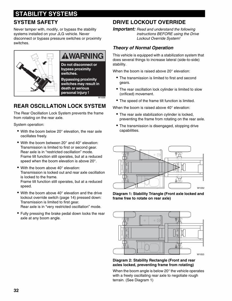
Diagram 1: Stability Triangle (Front axle locked and frame free to rotate on rear axle)
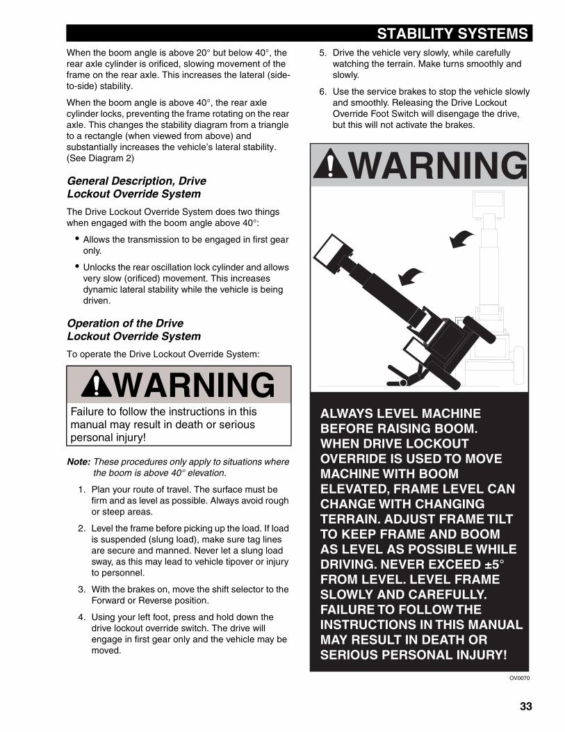
Diagram 2: Stability Rectangle (Front and rear axles locked, preventing frame from rotating)
When the boom angle is below 20° the vehicle operates with a freely oscillating rear axle to negotiate rough terrain. (See Diagram 1)
Do not disconnect or bypass proximity switches.
Bypassing proximity switches may result in death or serious personal injury !
W1056
W1052
W1053
32
STABILITY SYSTEMS
When the boom angle is above 20° but below 40°, the rear axle cylinder is orificed, slowing movement of the frame on the rear axle. This increases the lateral (side-to-side) stability.When the boom angle is above 40°, the rear axle cylinder locks, preventing the frame rotating on the rear axle. This changes the stability diagram from a triangle to a rectangle (when viewed from above) and substantially increases the vehicle’s lateral stability. (See Diagram 2)
General Description, DriveLockout Override System
The Drive Lockout Override System does two things when engaged with the boom angle above 40°:
• Allows the transmission to be engaged in first gear only.
• Unlocks the rear oscillation lock cylinder and allows very slow (orificed) movement. This increases dynamic lateral stability while the vehicle is being driven.
Operation of the Drive Lockout Override System
To operate the Drive Lockout Override System:
Note: These procedures only apply to situations where the boom is above 40° elevation.
1. Plan your route of travel. The surface must be firm and as level as possible. Always avoid rough or steep areas.
2. Level the frame before picking up the load. If load is suspended (slung load), make sure tag lines are secure and manned. Never let a slung load sway, as this may lead to vehicle tipover or injury to personnel.
3. With the brakes on, move the shift selector to the Forward or Reverse position.
4. Using your left foot, press and hold down the drive lockout override switch. The drive will engage in first gear only and the vehicle may be moved.
5. Drive the vehicle very slowly, while carefully watching the terrain. Make turns smoothly and slowly.
6. Use the service brakes to stop the vehicle slowly and smoothly. Releasing the Drive Lockout Override Foot Switch will disengage the drive, but this will not activate the brakes.
WARNINGFailure to follow the instructions in this manual may result in death or serious personal injury!
OV0070
�������
������������������������������������������ ������������������ ������ �������������������������������� ���������������������������������������������� ��������������������������� ��������������������������� ������������������� �!"������������������������������ ������������������������������������������������������������������ ����������������������� ���#
33
STABILITY SYSTEMS
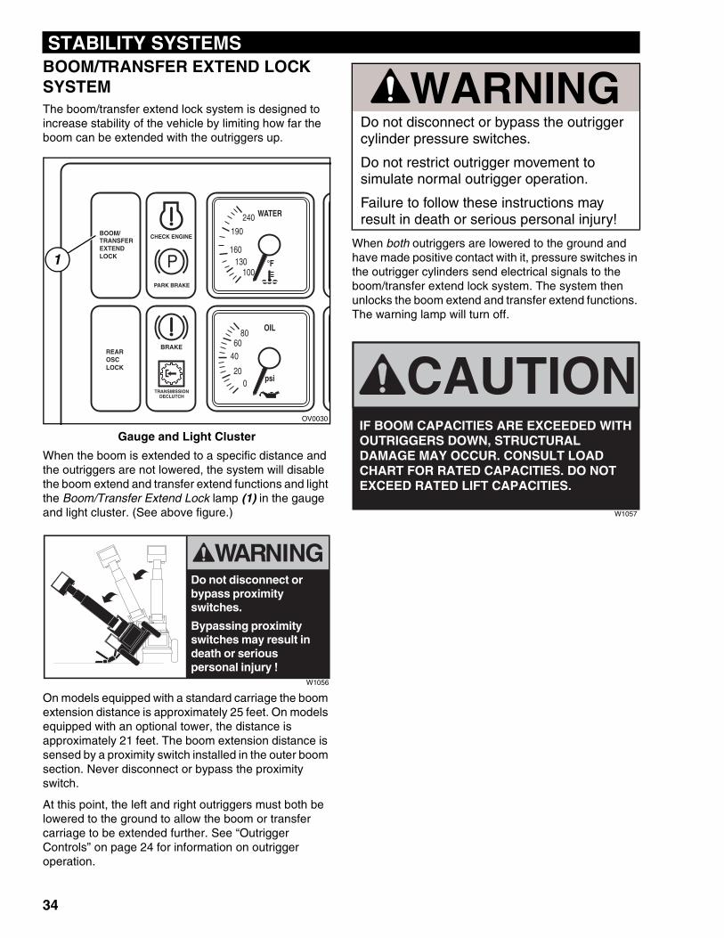
BOOM/TRANSFER EXTEND LOCK SYSTEMThe boom/transfer extend lock system is designed to increase stability of the vehicle by limiting how far the boom can be extended with the outriggers up.Gauge and Light Cluster
When the boom is extended to a specific distance and the outriggers are not lowered, the system will disable the boom extend and transfer extend functions and light the Boom/Transfer Extend Lock lamp (1) in the gauge and light cluster. (See above figure.)
On models equipped with a standard carriage the boom extension distance is approximately 25 feet. On models equipped with an optional tower, the distance is approximately 21 feet. The boom extension distance is sensed by a proximity switch installed in the outer boom section. Never disconnect or bypass the proximity switch.
At this point, the left and right outriggers must both be lowered to the ground to allow the boom or transfer carriage to be extended further. See “Outrigger Controls” on page 24 for information on outrigger operation.
When both outriggers are lowered to the ground and have made positive contact with it, pressure switches in the outrigger cylinders send electrical signals to the boom/transfer extend lock system. The system then unlocks the boom extend and transfer extend functions. The warning lamp will turn off.
���������������� ����
����������
�����
��������� �������
�����
����
������
������
���
� �����
������
����������
�
������������
1
OV0030
Do not disconnect or bypass proximity switches.
Bypassing proximity switches may result in death or serious personal injury !
W1056
WARNINGDo not disconnect or bypass the outrigger cylinder pressure switches.
Do not restrict outrigger movement to simulate normal outrigger operation.
Failure to follow these instructions may result in death or serious personal injury!
CAUTIONIF BOOM CAPACITIES ARE EXCEEDED WITH OUTRIGGERS DOWN, STRUCTURAL DAMAGE MAY OCCUR. CONSULT LOAD CHART FOR RATED CAPACITIES. DO NOT EXCEED RATED LIFT CAPACITIES.
W1057
34

STABILITY SYSTEMS
35
FLUID & LUBRICANT SPECIFICATIONS
GENERAL FLUID AND LUBRICANT SPECIFICATIONSENGINE OIL SPECIFICATIONS
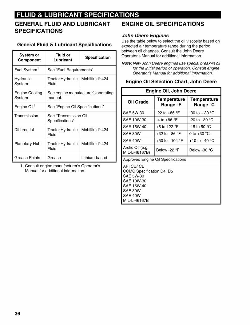
John Deere EnginesUse the table below to select the oil viscosity based on expected air temperature range during the period between oil changes. Consult the John Deere Operator’s Manual for additional information.
Note: New John Deere engines use special break-in oil for the initial period of operation. Consult engine Operator’s Manual for additional information.
General Fluid & Lubricant Specifications
System or Component
Fluid or Lubricant
Specification
Fuel System1
1. Consult engine manufacturer’s Operator’s Manual for additional information.
See “Fuel Requirements”
Hydraulic System
Tractor Hydraulic Fluid
Mobilfluid® 424
Engine Cooling System
See engine manufacturer’s operating manual.
Engine Oil1 See “Engine Oil Specifications”
Transmission See “Transmission Oil Specifications”
Differential Tractor Hydraulic Fluid
Mobilfluid® 424
Planetary Hub Tractor Hydraulic Fluid
Mobilfluid® 424
Grease Points Grease Lithium-based
Engine Oil Selection Chart, John Deere
Engine Oil, John Deere
Oil Grade Temperature Range °F
Temperature Range °C
SAE 5W-30 -22 to +86 °F -30 to + 30 °C
SAE 10W-30 -4 to +86 °F -20 to +30 °C
SAE 15W-40 +5 to 122 °F -15 to 50 °C
SAE 30W +32 to +86 °F 0 to +30 °C
SAE 40W +50 to +104 °F +10 to +40 °C
Arctic Oil (e.g. MIL-L-46167B)
Below -22 °F Below -30 °C
Approved Engine Oil Specifications
API CD/ CECCMC Specification D4, D5SAE 5W-30SAE 10W-30SAE 15W-40SAE 30WSAE 40WMIL-L-46167B
36
FLUID & LUBRICANT SPECIFICATIONS
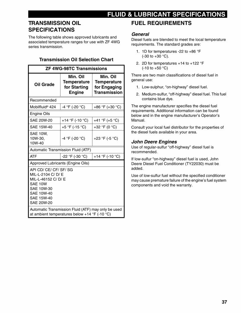
TRANSMISSION OIL SPECIFICATIONSThe following table shows approved lubricants and associated temperature ranges for use with ZF 4WG series transmission.FUEL REQUIREMENTS
GeneralDiesel fuels are blended to meet the local temperature requirements. The standard grades are:
1. 1D for temperatures -22 to +86 °F (-30 to +30 °C).
2. 2D for temperatures +14 to +122 °F (-10 to +50 °C)
There are two main classifications of diesel fuel in general use:
1. Low-sulphur, “on-highway” diesel fuel.
2. Medium-sulfur, “off-highway” diesel fuel. This fuel contains blue dye.
The engine manufacturer specifies the diesel fuel requirements. Additional information can be found below and in the engine manufacturer’s Operator’s Manual.
Consult your local fuel distributor for the properties of the diesel fuels available in your area.
John Deere EnginesUse of regular-sulfur “off-highway” diesel fuel is recommended.
If low-sulfur “on-highway” diesel fuel is used, John Deere Diesel Fuel Conditioner (TY22030) must be added.
Use of low-sulfur fuel without the specified conditioner may cause premature failure of the engine’s fuel system components and void the warranty.
Transmission Oil Selection Chart
ZF 4WG-98TC Transmissions
Oil Grade
Min. Oil Temperature for Starting
Engine
Min. Oil Temperature for Engaging Transmission
Recommended
Mobilfluid® 424 -4 °F (-20 °C) +86 °F (+30 °C)
Engine Oils
SAE 20W-20 +14 °F (-10 °C) +41 °F (+5 °C)
SAE 15W-40 +5 °F (-15 °C) +32 °F (0 °C)
SAE 10W, 10W-30, 10W-40
-4 °F (-20 °C) +23 °F (-5 °C)
Automatic Transmission Fluid (ATF)
ATF -22 °F (-30 °C) +14 °F (-10 °C)
Approved Lubricants (Engine Oils)
API CD/ CE/ CF/ SF/ SGMIL-L-2104 C/ D/ EMIL-L-46152 C/ D/ ESAE 10WSAE 10W-30SAE 10W-40SAE 15W-40SAE 20W-20
Automatic Transmission Fluid (ATF) may only be used at ambient temperatures below +14 °F (-10 °C)
37
38
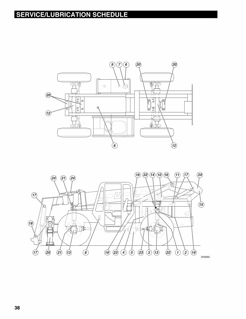
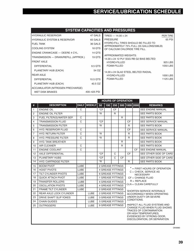
SERVICE/LUBRICATION SCHEDULE
����� ������������������� ��
��
����
��
����� ����� � ��
��
��
���
��
�
��
� �
OV0050
SERVICE/LUBRICATION SCHEDULE
39
����������������� ������������������������ �������
���� ��� �������
����������� � ��� �
��������������!���������" ��� �
������������!������������#�����$"% ��� �
�������� ���#�� ������������%
����!���"���&��� ��� ��
���'��(����) ������*����
������������� ��+�������� �(����� ������ �(���������,����� �����������*������� ������$��� ����(-������#((��������(���*%������������������� �������"
���� ��$�
������ ��� �"(� �
���� ������*�#���% (���.
�����$�
������ ��� ��"(� �
���� ������*�#���% ��"(��.
�����$��� ��)��� �/��"���0����������������*����*����*� ������,����� ��(��*�����,����� ��(���*�
��"���0���������� ��*� �������������,����� ������*�����,����� ���(��*�
$ 1��1
���1��1
����1
���� ���������� �����������������)������� ����������� ������������� ����"
��
*�������� �(
���� ����� ���
�� ������������� �
����� �������������� ������������������)������������)� ����������� ����� ����������� ���� ���2�������*��� ���������2��������� ���2��������� ���
��
������ �������� ��
������� �������� �
��
����� �� ��������
��
�����$��������������
��
��
��
��
�(
��������� ����������
�������������
� �������� ���������������3���
� ������������ � �3�
� ������� �#�%)� ����" ��
� ����������������� ��3���
( ��������������� � �3�
� ���"�������������� ���
� ���"�� ������� � �3��
� ���"����������� � �3��
� ���"� ����*�� �� �
�� ��������� ��
�� ����������� ���
�� �$�������� ��� ���3��
�� ���� ������*� ���3��
��������� ������*
��������� ������*
��������� ������*
��������� ������*
��������� ������*
��������� ������*
��������� ������*
��������� ����
��*
���� �������������� �������2���������������������������������������������
����� ��*���
����� ��*���
��������������
����� ��*���
����� ��*���
����� ��*���
��� ��������������
��*
��*�� ������ ��������� ����
����������� ��* (�������� ����
�������������
����� ��*���
����� ��*���
��������� ����
��������������
����������������
3� � ����� ��*������"���� �������� �
% ��������� ���� ������ "& '&& ("& "&& '&&& (&&& ������
��� ��������������
OV0060
SAMPLE LOAD CHART
0
5
10
15
20
25
30
35
40
0
1
2
3
4
5
6
7
8
10
9
11
12
-1
051015202530FEET
0123456789METERS
-5°
0°
10°
20°
30°
40°
60°
50°
70°
INDICATES REAR
OSCILLATION LOCK
ENGAGED
MAXIMUM BOOM LOAD CAPACITIES AT 24" LOAD CENTER, FOR LIFT AND REACH POSITIONS IN POUNDS AND FEET WITH METRIC CONVERSIONS.
MANUFACTURER'S RECOMMENDED CAPACITIES ARE IN CONFORMANCE WITH ANSI/ASME B56.6 STABILITY TESTS USING STANDARD HOMOGENEOUS CUBES 4' × 4' × 4'.
MANUFACTURER'S RECOMMENDED LOADS AND ANGLES SHOWN ARE AT THE HORIZONTAL CENTER OF GRAVITY OF THE ABOVE CUBE. CAPACITY ADJUSTMENT MUST BE MADE FOR EXTENDED LOAD CENTERS AND OTHER VARIATIONS OF LOAD SIZE, ETC.
RATED LIFT CAPACITIES SHOWN ARE WITH MACHINE ON A FIRM, LEVEL SURFACE WITH UNDAMAGED, PROPERLY INFLATED, BALLAST-FILLED TIRES.
CAPACITIES SHOWN DEPICT FULL BOOM EXTENSION PRIOR TO TRANSACTION.
20
00
LB
S /
90
0 K
G
10
00
LB
S /
45
0 K
G
30
00
LB
S /
13
60
KG
40
00
LB
S /
18
10
KG
50
00
LB
S /
22
60
KG
60
00
LB
S /
27
20
KG
ABCDEFGHIJTRANSACTION
80" (203 CM)
TRANSACTION80" (203 CM)
SAMPLE LOAD CHARTCONSULT LOAD CHART MOUNTED IN MACHINE
FOR YOUR MACHINE'S MODEL AND OPTIONAL ATTACHMENT CAPACITIES
R1025
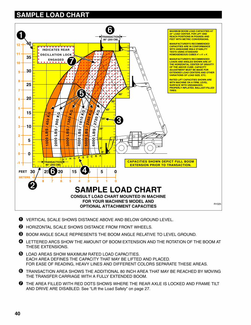
➊ VERTICAL SCALE SHOWS DISTANCE ABOVE AND BELOW GROUND LEVEL.
➋ HORIZONTAL SCALE SHOWS DISTANCE FROM FRONT WHEELS.
➌ BOOM ANGLE SCALE REPRESENTS THE BOOM ANGLE RELATIVE TO LEVEL GROUND.
➍ LETTERED ARCS SHOW THE AMOUNT OF BOOM EXTENSION AND THE ROTATION OF THE BOOM AT THESE EXTENSIONS.
➎ LOAD AREAS SHOW MAXIMUM RATED LOAD CAPACITIES.EACH AREA DEFINES THE CAPACITY THAT MAY BE LIFTED AND PLACED.FOR EASE OF READING, HEAVY LINES AND DIFFERENT COLORS SEPARATE THESE AREAS.
➏ TRANSACTION AREA SHOWS THE ADDITIONAL 80 INCH AREA THAT MAY BE REACHED BY MOVING THE TRANSFER CARRIAGE WITH A FULLY EXTENDED BOOM.
➐ THE AREA FILLED WITH RED DOTS SHOWS WHERE THE REAR AXLE IS LOCKED AND FRAME TILT AND DRIVE ARE DISABLED. See “Lift the Load Safely” on page 27.
40
CALIFORNIA PROPOSITION 65
BATTERY WARNINGBattery posts,
terminals and relatedaccessories contain
lead and lead compounds,chemical known to the
State of Californiato cause cancer andreproductive harm.
WASH HANDSAFTER HANDLING!
CALIFORNIA PROPOSITION 65
EXHAUST WARNINGDiesel Engine exhaust and some of its constituents are known to the State of
California to cause cancer, birth defects and other
reproductive harm.
JLG Worldwide Locations
��������������� ����������
JLG Industries (Australia)P.O. Box 511911 Bolwarra RoadPort MacquarieN.S.W. 2444AustraliaPhone: +61 265 811 111Fax: +61 265 810 122
JLG Latino Americana Ltda.Rua Eng. Carlos Stevenson,80-Suite 7113092-310 Campinas-SPBrazilPhone: +55 193 295 0407Fax: +55 193 295 1025
JLG Industries (UK) LtdBentley HouseBentley AvenueMiddletonGreater ManchesterM24 2GPEnglandPhone: +44 (0)161 654 1000Fax: +44 (0)161 654 1001
JLG France SASZ.I. de Baulieu47400 FauilletFrancePhone: +33 (0)5 53 88 31 70Fax: +33 (0)5 53 88 31 79
JLG Deutschland GmbHMax-Planck-Str. 21D - 27721 Ritterhude-lhlpohlGermanyPhone: +49 (0)421 69 350 20Fax: +49 (0)421 69 350 45
JLG Equipment Services Ltd.Rm 1107 Landmark North39 Lung Sum AvenueSheung Shui N.T.Hong KongPhone: +852 2639 5783Fax: +852 2639 5797
JLG Industries (Italia) s.r.l.Via Po. 2220010 Pregnana Milanese - MIItalyPhone: +39 029 359 5210Fax: +39 029 359 5845
JLG Europe B.V.Polaris Avenue 632132 JH HoofddorpThe NetherlandsPhone: +31 (0)23 565 5665Fax: +31 (0)23 557 2493
JLG PolskaUI. Krolewska00-060 WarsawaPolandPhone: +48 (0)914 320 245Fax: +48 (0)914 358 200
JLG Industries (Scotland)Wright Business Centre1 Lonmay RoadQueenslie, Glasgow G33 4ELScotlandPhone: +44 (0)141 781 6700Fax: +44 (0)141 773 1907
Plataformas Elevadoras JLG Iberica, S.L.Trapadella, 2P.I. Castellbisbal Sur08755Castellbisbal, BarcelonaSpainPhone: +34 93 772 4 700Fax: +34 93 771 1762
JLG Sverige ABEnkopingsvagen 150Box 704SE - 176 27 JarfallaSwedenPhone: +46 (0)850 659 500Fax: +46 (0)850 659 534
JLG Industries, Inc.
1 JLG Drive
McConnellsburg PA. 17233-9533
USA
Phone: +1-717-485-5161
Customer Support Toll Free: 1-877-554-5438
Fax: +1-717-485-6417