Embed Size (px)
Citation preview
Model RC-1 Retard Chamber For Variable Pressure Wet Pipe Sprinkler Systems 300 psi (20,7 bar)
Page 1 of 4 FEBRUARY 2017 TFP920
Worldwide Contacts www.tyco-fire.com
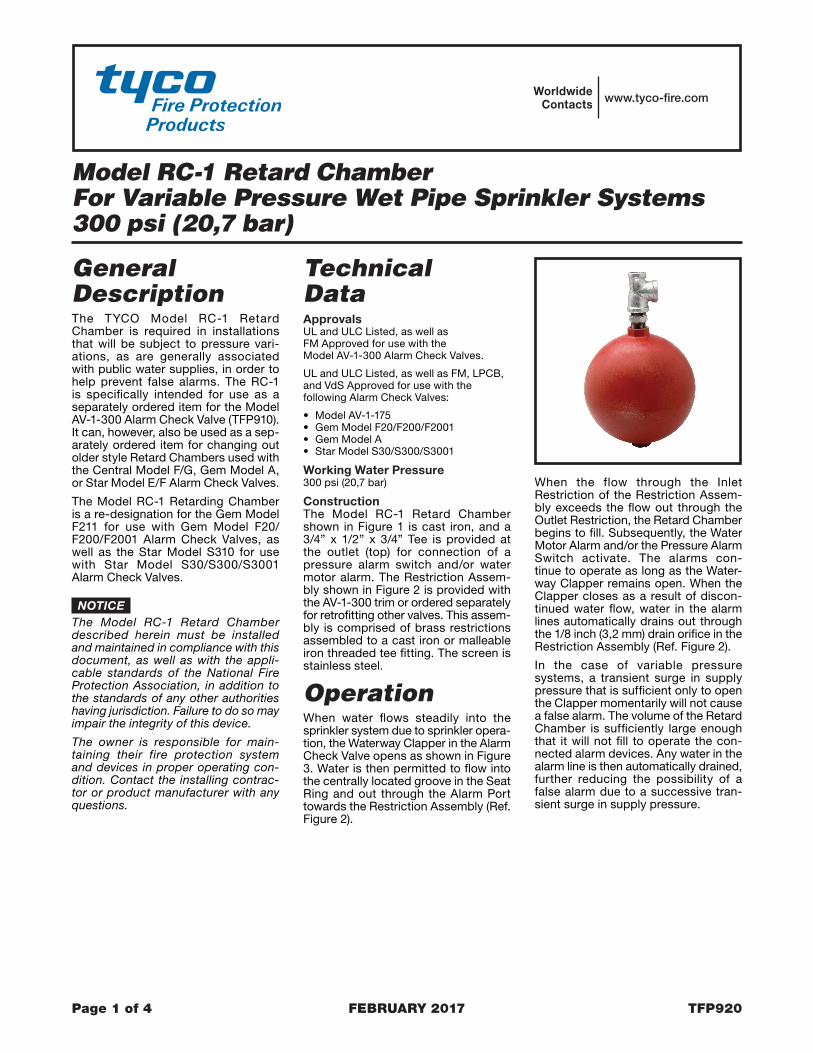
General DescriptionThe TYCO Model RC-1 Retard Chamber is required in installations that will be subject to pressure vari-ations, as are generally associated with public water supplies, in order to help prevent false alarms. The RC-1 is specifically intended for use as a separately ordered item for the Model AV-1-300 Alarm Check Valve (TFP910). It can, however, also be used as a sep-arately ordered item for changing out older style Retard Chambers used with the Central Model F/G, Gem Model A, or Star Model E/F Alarm Check Valves.
The Model RC-1 Retarding Chamber is a re-designation for the Gem Model F211 for use with Gem Model F20/F200/F2001 Alarm Check Valves, as well as the Star Model S310 for use with Star Model S30/S300/S3001 Alarm Check Valves.
NOTICEThe Model RC-1 Retard Chamber described herein must be installed and maintained in compliance with this document, as well as with the appli-cable standards of the National Fire Protection Association, in addition to the standards of any other authorities having jurisdiction. Failure to do so may impair the integrity of this device.
The owner is responsible for main-taining their fire protection system and devices in proper operating con-dition. Contact the installing contrac-tor or product manufacturer with any questions.
Technical DataApprovalsUL and ULC Listed, as well as FM Approved for use with the Model AV-1-300 Alarm Check Valves.
UL and ULC Listed, as well as FM, LPCB, and VdS Approved for use with the following Alarm Check Valves:
• Model AV-1-175• Gem Model F20/F200/F2001• Gem Model A• Star Model S30/S300/S3001
Working Water Pressure300 psi (20,7 bar)
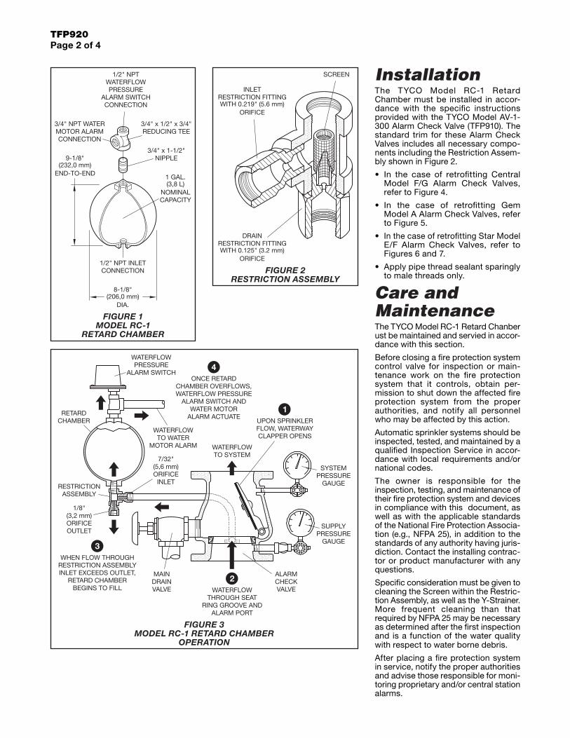
ConstructionThe Model RC-1 Retard Chamber shown in Figure 1 is cast iron, and a 3/4” x 1/2” x 3/4” Tee is provided at the outlet (top) for connection of a pressure alarm switch and/or water motor alarm. The Restriction Assem-bly shown in Figure 2 is provided with the AV-1-300 trim or ordered separately for retrofitting other valves. This assem-bly is comprised of brass restrictions assembled to a cast iron or malleable iron threaded tee fitting. The screen is stainless steel.
OperationWhen water flows steadily into the sprinkler system due to sprinkler opera-tion, the Waterway Clapper in the Alarm Check Valve opens as shown in Figure 3. Water is then permitted to flow into the centrally located groove in the Seat Ring and out through the Alarm Port towards the Restriction Assembly (Ref. Figure 2).
When the flow through the Inlet Restriction of the Restriction Assem-bly exceeds the flow out through the Outlet Restriction, the Retard Chamber begins to fill. Subsequently, the Water Motor Alarm and/or the Pressure Alarm Switch activate. The alarms con-tinue to operate as long as the Water-way Clapper remains open. When the Clapper closes as a result of discon-tinued water flow, water in the alarm lines automatically drains out through the 1/8 inch (3,2 mm) drain orifice in the Restriction Assembly (Ref. Figure 2).
In the case of variable pressure systems, a transient surge in supply pressure that is sufficient only to open the Clapper momentarily will not cause a false alarm. The volume of the Retard Chamber is sufficiently large enough that it will not fill to operate the con-nected alarm devices. Any water in the alarm line is then automatically drained, further reducing the possibility of a false alarm due to a successive tran-sient surge in supply pressure.
TFP920Page 2 of 4
InstallationThe TYCO Model RC-1 Retard Chamber must be installed in accor-dance with the specific instructions provided with the TYCO Model AV-1-300 Alarm Check Valve (TFP910). The standard trim for these Alarm Check Valves includes all necessary compo-nents including the Restriction Assem-bly shown in Figure 2.
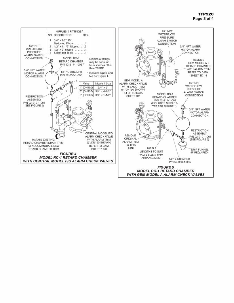
• In the case of retrofitting Central Model F/G Alarm Check Valves, refer to Figure 4.
• In the case of retrofitting Gem Model A Alarm Check Valves, refer to Figure 5.
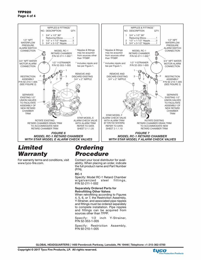
• In the case of retrofitting Star Model E/F Alarm Check Valves, refer to Figures 6 and 7.
• Apply pipe thread sealant sparingly to male threads only.
Care and MaintenanceThe TYCO Model RC-1 Retard Chanber ust be maintained and servied in accor-dance with this section.
Before closing a fire protection system control valve for inspection or main-tenance work on the fire protection system that it controls, obtain per-mission to shut down the affected fire protection system from the proper authorities, and notify all personnel who may be affected by this action.
Automatic sprinkler systems should be inspected, tested, and maintained by a qualified Inspection Service in accor-dance with local requirements and/or national codes.
The owner is responsible for the inspection, testing, and maintenance of their fire protection system and devices in compliance with this document, as well as with the applicable standards of the National Fire Protection Associa-tion (e.g., NFPA 25), in addition to the standards of any authority having juris-diction. Contact the installing contrac-tor or product manufacturer with any questions.
Specific consideration must be given to cleaning the Screen within the Restric-tion Assembly, as well as the Y-Strainer. More frequent cleaning than that required by NFPA 25 may be necessary as determined after the first inspection and is a function of the water quality with respect to water borne debris.
After placing a fire protection system in service, notify the proper authorities and advise those responsible for moni-toring proprietary and/or central station alarms.
3/4" x 1/2" x 3/4"REDUCING TEE
3/4" x 1-1/2"
END-TO-END
8-1/8"(206,0 mm)
DIA.
1/2" NPT INLETCONNECTION
3/4" NPT WATER
CONNECTIONMOTOR ALARM
9-1/8"(232,0 mm)
WATERFLOW
CONNECTION
PRESSUREALARM SWITCH
1/2" NPT
1 GAL.(3,8 L)
CAPACITYNOMINAL
NIPPLE
SCREEN
ORIFICE
ORIFICEWITH 0.125" (3.2 mm)
RESTRICTION FITTING
WITH 0.219" (5.6 mm)RESTRICTION FITTING
DRAIN
INLET
PRESSUREWATERFLOW
ALARM SWITCH
MOTOR ALARM
VALVE
(3,2 mm)
OUTLETORIFICE
RETARD CHAMBERBEGINS TO FILL
INLET EXCEEDS OUTLET,RESTRICTION ASSEMBLYWHEN FLOW THROUGH
ASSEMBLY
1/8"
CHAMBERRETARD
INLET
ALARM PORTRING GROOVE AND
THROUGH SEATWATERFLOW
MAINDRAIN
ALARM ACTUATE
WATERFLOW PRESSURECHAMBER OVERFLOWS,
ONCE RETARD
WATER MOTORALARM SWITCH AND
WATERFLOWTO SYSTEM
WATERFLOWTO WATER
7/32"
ORIFICE(5,6 mm)
UPON SPRINKLERFLOW, WATERWAYCLAPPER OPENS
GAUGE
GAUGE
SUPPLY
RESTRICTION
PRESSURE
PRESSURESYSTEM
CHECKVALVE
ALARM
FIGURE 1 MODEL RC-1
RETARD CHAMBER
FIGURE 2 RESTRICTION ASSEMBLY
FIGURE 3 MODEL RC-1 RETARD CHAMBER
OPERATION
TFP920Page 3 of 4
1/2" x 2" NippleSelect per Table
DESCRIPTION
3/4" x 1/2" 90°Reducing Elbow
NIPPLES & FITTINGS
1/2" x 1-1/2" Nipple34
1
2
NO.
than TFSBP.
Includes nipple andtee per Figure 1.
Nipples & fittings
from sources othermay be acquired
1. . . . . . . .. . . . . . .
2
1
1
. . . . . . . .. . . . .3
1
QTY.
1
P/N 52-353-1-0051/2" Y-STRAINER
RETARD CHAMBERP/N 52-211-1-002
RETARD CHAMBER DRAIN TRIM
3RESTRICTIONASSEMBLY
P/N 92-210-1-005
TO ACCOMMODATE NEWRETARD CHAMBER TRIM
(SEE FIGURE 2)
ROTATE EXISTING
WATERFLOW
CONNECTION
PRESSUREALARM SWITCH
1/2" NPT
3/4" NPT WATER
CONNECTIONMOTOR ALARM
2
2
WITH ALARM TRIM
REFER TO DATASHEET 7-3.0
(6"/DN150 SHOWN)
ALARM CHECK VALVECENTRAL MODEL F/G
24
1
MODEL RC-1
2
8" (DN200) 3/4" x 1-1/2"3/4" x 4-1/2"
Nipple 4 SizeValve
4" (DN100)6" (DN150)
3/4" x 6"
ALARM SWITCHPRESSURE
CONNECTION
WATERFLOW
1/2" Y-STRAINERP/N 52-353-1-005
VALVE SIZE & TRIMLENGTHS TO SUIT
ARRANGEMENT
NIPPLE
WITH BASIC TRIMALARM CHECK VALVE
(6"/DN150 SHOWN)REFER TO DATA
GEM MODEL A
SHEET TD1
MOTOR ALARM
POINT
CONNECTION
DRIP FUNNEL(IF REQUIRED)
P/N 92-210-1-005ASSEMBLY
(SEE FIGURE 2)
RESTRICTION
1/2" NPT
ALARM SWITCH
WATERFLOW
CONNECTION
PRESSURE
3/4" NPT WATER
MOTOR ALARMCONNECTION
3/4" NPT WATER
RETARD CHAMBER
REFER TO DATAWITH ALARM TRIM
GEM MODEL A-3
SHEET TD1-1
REMOVE
ALARM TRIM
REMOVEORIGINAL
TO THIS
1/2" NPT
RETARD CHAMBERP/N 52-211-1-002
MODEL RC-1
TEE PER FIGURE 1)(INCLUDES NIPPLE &
FIGURE 4 MODEL RC-1 RETARD CHAMBER
WITH CENTRAL MODEL F/G ALARM CHECK VALVES
FIGURE 5 MODEL RC-1 RETARD CHAMBER
WITH GEM MODEL A ALARM CHECK VALVES
GLOBAL HEADQUARTERS | 1400 Pennbrook Parkway, Lansdale, PA 19446 | Telephone +1-215-362-0700
TFP920Page 4 of 4
Copyright © 2017 Tyco Fire Products, LP. All rights reserved.
Limited WarrantyFor warranty terms and conditions, visit www.tyco-fire.com.
Ordering ProcedureContact your local distributor for avail-ability. When placing an order, indicate the full product name and Part Number (P/N).
RC-1Specify: Model RC-1 Retard Chamber w/ga lvan ized s tee l f i t t ings , P/N 52-211-1-002
Separately Ordered Parts for Retrofitting Other ValvesWhen retrofitting according to Figures 4, 5, 6, or 7, the Restriction Assembly, Y-Strainer, and associated pipe nipples and fittings must be ordered separately to complete installation. Pipe nipples and fittings can be acquired from sources other than TFPP.
Specify: 1/2 inch Y-Strainer, P/N 52-353-1-005
Specify: Restriction Assembly, P/N 92-210-1-005
may be acquiredfrom sources other
Nipples & fittings
tee per Figure 1.Includes nipple and
. . . . .13 3/4" x 3-1/2" Nipple
than TFSBP.
2
1
1/2" x 1-1/2" Nipple
NIPPLES & FITTINGS
Reducing Elbow3/4" x 1/2" 90°
DESCRIPTION
1
2
NO.
. . . . .. . . . . . . .
31
QTY.
1
DISCARD EXISTING
STAR MODEL E
REFER TO DATASHEET 2-1.1.20
ALARM CHECK VALVEWITH ALARM TRIM
(SEE FIGURE 2)2
SEPARATE
CHAMBER
EXISTING 1/2"
TO FACILITATEUNION HALVES
ASSEMBLY OFNEW RETARD
RETARD CHAMBER DRAIN TRIM
TRIM
RETARD CHAMBER TRIMTO ACCOMMODATE NEW
ROTATE EXISTING
MOTOR ALARMCONNECTION
3/4" NPT WATER
1/2" NPT
ALARM SWITCHPRESSURE
CONNECTION
WATERFLOW
P/N 92-210-1-005ASSEMBLY
RESTRICTION
MODEL RC-1
P/N 52-211-1-002RETARD CHAMBER
1/2" Y-STRAINERP/N 52-353-1-005
22 3/4" x 2" NIPPLE
REMOVE AND3
1
2
2(SEE FIGURE 2)
TO ACCOMMODATE NEWRETARD CHAMBER TRIM
ROTATE EXISTINGRETARD CHAMBER DRAIN TRIM(6"/DN150 SHOWN)
REFER TO DATASHEET 2-1.1.10
ALARM CHECK VALVEWITH ALARM TRIM
STAR MODEL F
TO FACILITATE
TRIM
NEW RETARDASSEMBLY OF
CHAMBER
UNION HALVESEXISTING 1/2"
SEPARATE
REMOVE ANDDISCARD EXISTING
3/4" x 2" NIPPLE
1/2" Y-STRAINERP/N 52-353-1-005
3
1
2
MODEL RC-1RETARD CHAMBERP/N 52-211-1-002 2
PRESSURE
MOTOR ALARM
RESTRICTIONASSEMBLY
CONNECTION
P/N 92-210-1-005
2
CONNECTIONALARM SWITCH
3/4" NPT WATER
WATERFLOW1/2" NPT
QTY.
. . . . . . . .. . . . .. . . . .3 3/4" x 3-1/2" Nipple
Includes nipple andtee per Figure 1.
Nipples & fittings
than TFSBP.from sources othermay be acquired
2
1
NO.
Reducing Elbow
NIPPLES & FITTINGSDESCRIPTION
3/4" x 1/2" 90°
1/2" x 1-1/2" Nipple
1
2
1
131
FIGURE 6 MODEL RC-1 RETARD CHAMBER
WITH STAR MODEL E ALARM CHECK VALVES
FIGURE 7 MODEL RC-1 RETARD CHAMBER
WITH STAR MODEL F ALARM CHECK VALVES