Embed Size (px)
Citation preview
Instruction manual
Modbus slave interface for digital
Mass Flow / Pressure instruments
Doc. no.: 9.17.035S Date: 27-03-2013
ATTENTION Please read this instruction manual carefully before installing and operating the instrument. Not following the guidelines could result in personal injury and/or damage to the equipment.
Head Office: Nijverheidsstraat 1a, NL‐7261 AK Ruurlo, The Netherlands, Tel. +31 573 458800, [email protected]
BRONKHORST®
Page 2 Modbus interface 9.17.035
Disclaimer
Even though care has been taken in the preparation and publication of the contents of this manual, we do not assume legal or other liability for any inaccuracy, mistake, mis‐statement or any other error of whatsoever nature contained herein. The material in this manual is for information purposes only, and is subject to change without notice. Bronkhorst High‐Tech B.V. July 2011
Symbols
Important information. Discarding this information could cause injuries to people or damage to the Instrument or installation.
Helpful information. This information will facilitate the use of this instrument.
Additional info available on the internet or from your local sales representative.
Warranty The products of Bronkhorst High‐Tech B.V. are warranteed against defects in material and workmanship for a period of three years from the date of shipment, provided they are used in accordance with the ordering specifications and the instructions in this manual and that they are not subjected to abuse, physical damage or contamination. Products that do not operate properly during this period may be repaired or replaced at no charge. Repairs are normally warranted for one year or the balance of the original warranty, whichever is the longer.
See also paragraph 9 of the Conditions of sales: http://www.bronkhorst.com/files/corporate_headquarters/sales_conditions/en_general_terms_of_sales.pdf
The warranty includes all initial and latent defects, random failures, and undeterminable internal causes. It excludes failures and damage caused by the customer, such as contamination, improper electrical hook‐up, physical shock etc. Re‐conditioning of products primarily returned for warranty service that is partly or wholly judged non‐warranty may be charged for. Bronkhorst High‐Tech B.V. or affiliated company prepays outgoing freight charges when any party of the service is performed under warranty, unless otherwise agreed upon beforehand. However, if the product has been returned collect to our factory or service center, these costs are added to the repair invoice. Import and/or export charges, foreign shipping methods/carriers are paid for by the customer.
BRONKHORST®
Page 3 Modbus interface 9.17.035
Table of contents
1 GENERAL PRODUCT INFORMATION....................................................................................................4 1.1 INTRODUCTION .............................................................................................................................................4 1.2 MULTIBUS TYPES ...........................................................................................................................................4 1.3 REFERENCES TO OTHER APPLICABLE DOCUMENTS ...................................................................................................5 1.3.1 Manuals and user guides: ........................................................................................................................... 5 1.3.2 Technical Drawings: .................................................................................................................................... 5 1.3.3 Software tooling: ........................................................................................................................................ 5
1.4 SHORT FORM START‐UP...................................................................................................................................6 2 FIELD BUS INSTALLATION ...................................................................................................................7 2.1 GENERAL.....................................................................................................................................................7 2.2 MODBUS CONNECTOR ....................................................................................................................................7 2.2.1 Shielded RJ45 modular jack......................................................................................................................... 7 2.2.2 Shielded a coded M12 connector ................................................................................................................ 8
2.3 MODBUS CABLES AND T‐PARTS.........................................................................................................................9 2.3.1 RJ45 FTP cables ........................................................................................................................................... 9 2.3.2 M12 DeviceNet drop cables ...................................................................................................................... 10
2.4 TERMINATION ............................................................................................................................................ 11 2.4.1 Termination resistors ................................................................................................................................ 11 2.4.2 Biasing resistors ........................................................................................................................................ 11
3 CHANGING SLAVE ADDRESS AND BAUD RATE ..................................................................................13 3.1 VIA ROTARY SWITCHES ON THE SIDE OF THE INSTRUMENT (IF PRESENT) ...................................................................... 13 3.2 VIA RS232: FLOWFIX .................................................................................................................................. 13 3.3 VIA RS232: OTHER PROGRAMS ...................................................................................................................... 14 3.4 VIA MICRO‐SWITCH AND LED’S ON THE INSTRUMENT (IF PRESENT)........................................................................... 14 3.4.1 Readout bus‐address/MAC‐ID and baud rate:.......................................................................................... 14 3.4.2 Change bus‐address and baud rate: ......................................................................................................... 15
3.5 BY USER INTERFACE (IF PRESENT) ..................................................................................................................... 15 4 FUNCTIONAL DESCRIPTION ..............................................................................................................16 4.1 GENERAL................................................................................................................................................... 16 4.2 IMPLEMENTATION CLASS ............................................................................................................................... 16 4.3 RESPONSE TIME .......................................................................................................................................... 17 4.4 SUPPORTED MODBUS FUNCTIONS.................................................................................................................... 17 4.4.1 Read Holding Registers (03)...................................................................................................................... 17 4.4.2 Write Single Register (06) ......................................................................................................................... 17 4.4.3 Write Multiple Registers (16) .................................................................................................................... 17 4.4.4 Diagnostics (08) ........................................................................................................................................ 18 4.4.5 Report Slave ID (17) .................................................................................................................................. 18 4.4.6 Available parameters................................................................................................................................ 19
5 TROUBLESHOOTING .........................................................................................................................21 5.1 VISUAL DIAGNOSTICS.................................................................................................................................... 21 5.2 STEP‐BY‐STEP ............................................................................................................................................. 21 5.3 BUS DIAGNOSTICS STRING.............................................................................................................................. 22
6 SERVICE............................................................................................................................................23
BRONKHORST®
1 GENERAL PRODUCT INFORMATION
1.1 Introduction This manual covers the Modbus interface, which offers a direct connection to Modbus for Bronkhorst1) digital mass‐flow / pressure meters / controllers. The Modbus instrument will behave as a slave. This means all communication (instructions / readout) will be performed by a master device on the same Modbus system. Mostly this will be a PC controlling a process. This manual explains how to install a Bronkhorst strument to your Modbus system.
h‐Tech B.V. , Bronkhorst Cori‐Tech B.V. and M+W Instruments GmbH.
Page 4 Modbus interface 9.17.035
in 1) Bronkhorst: This includes Bronkhorst Hig
.modbus.orgMore detailed information about Modbus can be found at www or any website of the (local) Modbus organisation of your country (when available).
imp d ndards: .pdf
The lementation of the Modbus interface is base on the following sta[1] Modbus_Application_Protocol_V1_1b [2] Modbus_over_serial_line_V1_02.pdf
December 28, 2006 December 20, 2006
1.2 Multibus types
s several improved functions like reverse voltage protection, inrush urrent limitation and overvoltage protection.
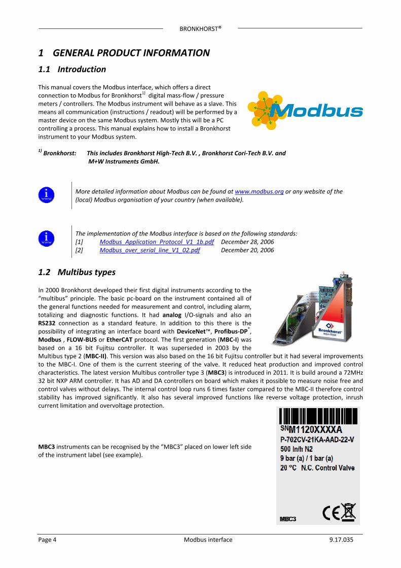
the “MBC3” placed on lower left side f the instrument label (see example).
In 2000 Bronkhorst developed their first digital instruments according to the “multibus” principle. The basic pc‐board on the instrument contained all of the general functions needed for measurement and control, including alarm, totalizing and diagnostic functions. It had analog I/O‐signals and also an RS232 connection as a standard feature. In addition to this there is the possibility of integrating an interface board with DeviceNet™, Profibus‐DP®, Modbus , FLOW‐BUS or EtherCAT protocol. The first generation (MBC‐I) was based on a 16 bit Fujitsu controller. It was superseded in 2003 by the Multibus type 2 (MBC‐II). This version was also based on the 16 bit Fujitsu controller but it had several improvements to the MBC‐I. One of them is the current steering of the valve. It reduced heat production and improved control characteristics. The latest version Multibus controller type 3 (MBC3) is introduced in 2011. It is build around a 72MHz 32 bit NXP ARM controller. It has AD and DA controllers on board which makes it possible to measure noise free and control valves without delays. The internal control loop runs 6 times faster compared to the MBC‐II therefore control stability has improved significantly. It also hac MBC3 instruments can be recognised byo
BRONKHORST®
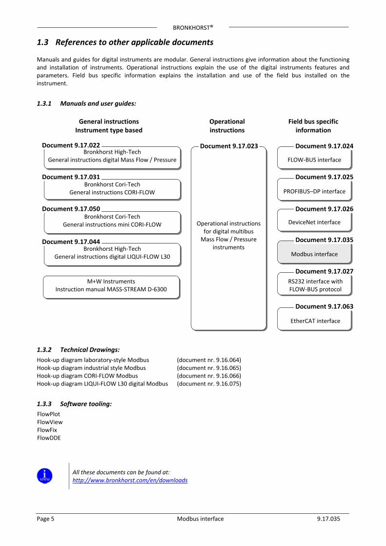
1.3 References to other applicable documents Manuals and guides for digital instruments are modular. General instructions give information about the functioning and installation of instruments. Operational instructions explain the use of the digital instruments features and parameters. Field bus specific information explains the installation and use of the field bus installed on the instrument.
1.3.1 Manuals and user guides:
General instructions Instrument type based
Operational instructions
Field bus specific information
Page 5 Modbus interface 9.17.035
1.3.2 Technical Drawings:
Hook‐up diagram laboratory‐style Modbus (document nr. 9.16.064) Hook‐up diagram industrial style Modbus (document nr. 9.16.065) Hook‐up diagram CORI‐FLOW Modbus (document nr. 9.16.066) Hook‐up diagram LIQUI‐FLOW L30 digital Modbus (document nr. 9.16.075)
1.3.3 Software tooling:
FlowPlot FlowView FlowFix FlowDDE
All these documents can be found at: http://www.bronkhorst.com/en/downloads
Operational instructions for digital multibus Mass Flow / Pressure
instruments
Bronkhorst High‐Tech Document 9.17.023
General instructions digital Mass Flow / Pressure
Bronkhorst Cori‐Tech General instructions CORI‐FLOW
Bronkhorst Cori‐Tech General instructions mini CORI‐FLOW
Bronkhorst High‐Tech General instructions digital LIQUI‐FLOW L30
Document 9.17.022
Document 9.17.031
Document 9.17.044
Document 9.17.050
Modbus interface
Document 9.17.035
DeviceNet interface
Document 9.17.026
PROFIBUS–DP interface
Document 9.17.025
Document 9.17.024
FLOW‐BUS interface
Document 9.17.027
M+W Instruments Instruction manual MASS‐STREAM D‐6300
RS232 interface with FLOW‐BUS protocol
EtherCAT interface
Document 9.17.063
BRONKHORST®
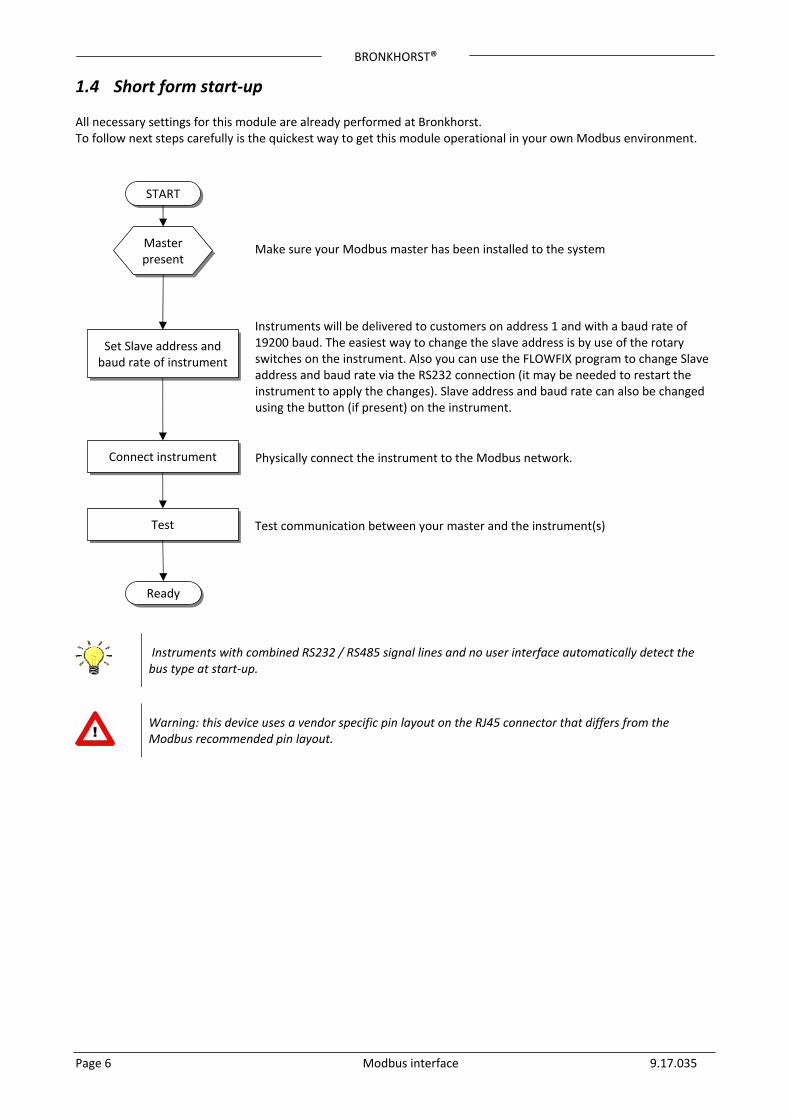
1.4 Short form start‐up All necessary settings for this module are already performed at Bronkhorst. To follow next steps carefully is the quickest way to get this module operational in your own Modbus environment.
Master present
Set Slave address and baud rate of instrument
Make sure your Modbus master has been installed to the system
Connect instrument
Test
Ready
Instruments will be delivered to customers on address 1 and with a baud rate of 19200 baud. The easiest way to change the slave address is by use of the rotary switches on the instrument. Also you can use the FLOWFIX program to change Slave address and baud rate via the RS232 connection (it may be needed to restart the instrument to apply the changes). Slave address and baud rate can also be changed using the button (if present) on the instrument.
START
Physically connect the instrument to the Modbus network.
Test communication between your master and the instrument(s)
Page 6 Modbus interface 9.17.035
Instruments with combined RS232 / RS485 signal lines and no user interface automatically detect the bus type at start‐up.
Warning: this device uses a vendor specific pin layout on the RJ45 connector that differs from the Modbus recommended pin layout.
BRONKHORST®
2 FIELD BUS INSTALLATION
2.1 General Modbus is a 3‐wire, RS485‐based field bus communication system for parameter value exchange. In this system each instrument / device is equipped with a micro‐controller for its own dedicated task but also for exchanging parameter value information with other instruments / devices connected to the same Modbus system.
Page 7 Modbus interface 9.17.035
1 8
The implementation of the Modbus interface is based on the following standards: [1] Modbus_Application_Protocol_V1_1b.pdf December 28, 2006 [2] Modbus_over_serial_line_V1_02.pdf December 20, 2006
Physical layer and communication protocol are detected automatically upon reception of messages. These messages must be sent using the correct combination of physical layer and communication protocol. After every power‐up the communication detection mode is active.
Bronkhorst advices not to use more as 127 instruments in one bus system.
2.2 Modbus connector
2.2.1 Shielded RJ45 modular jack
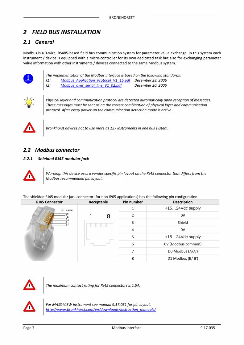
Warning: this device uses a vendor specific pin layout on the RJ45 connector that differs from the Modbus recommended pin layout.
The shielded RJ45 modular jack connector (for non IP65 applications) has the following pin configuration:
RJ45 Connector Receptable Pin number Description
1 +15…24Vdc supply
2 0V
3 Shield
4 0V
5 +15…24Vdc supply
6 0V (Modbus common)
7 D0 Modbus (A/A')
8 D1 Modbus (B/ B')
The maximum contact rating for RJ45 connectors is 1.5A.
For MASS‐VIEW instrument see manual 9.17.051 for pin layout. http://www.bronkhorst.com/en/downloads/instruction_manuals/
BRONKHORST®
2.2.2 Shielded a coded M12 connector
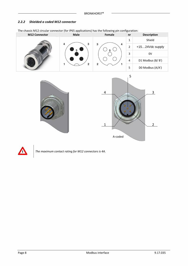
The chassis M12 circular connector (for IP65 applications) has the following pin configuration:
M12 Connector Male Female nr Description
1 Shield
2 +15…24Vdc supply
3 0V
4 D1 Modbus (B/ B')
5 D0 Modbus (A/A')
A‐coded
4
2
3
5
1
Page 8 Modbus interface 9.17.035
The maximum contact rating for M12 connectors is 4A.
BRONKHORST®
2.3 Modbus Cables and T‐parts
2.3.1 RJ45 FTP cables
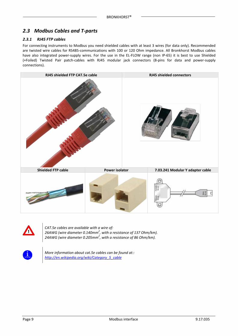
For connecting instruments to Modbus you need shielded cables with at least 3 wires (for data only). Recommended are twisted wire cables for RS485‐communications with 100 or 120 Ohm impedance. All Bronkhorst Modbus cables have also integrated power‐supply wires. For the use in the EL‐FLOW range (non IP‐65) it is best to use Shielded (+Foiled) Twisted Pair patch‐cables with RJ45 modular jack connectors (8‐pins for data and power‐supply connections).
RJ45 shielded FTP CAT.5e cable RJ45 shielded connectors
Shielded FTP cable Power isolator 7.03.241 Modular Y adapter cable
Page 9 Modbus interface 9.17.035
CAT.5e cables are available with a wire of: 26AWG (wire diameter 0.140mm2, with a resistance of 137 Ohm/km). 24AWG (wire diameter 0.205mm2, with a resistance of 86 Ohm/km).
More information about cat.5e cables can be found at:: http://en.wikipedia.org/wiki/Category_5_cable
BRONKHORST®
2.3.2 M12 DeviceNet drop cables
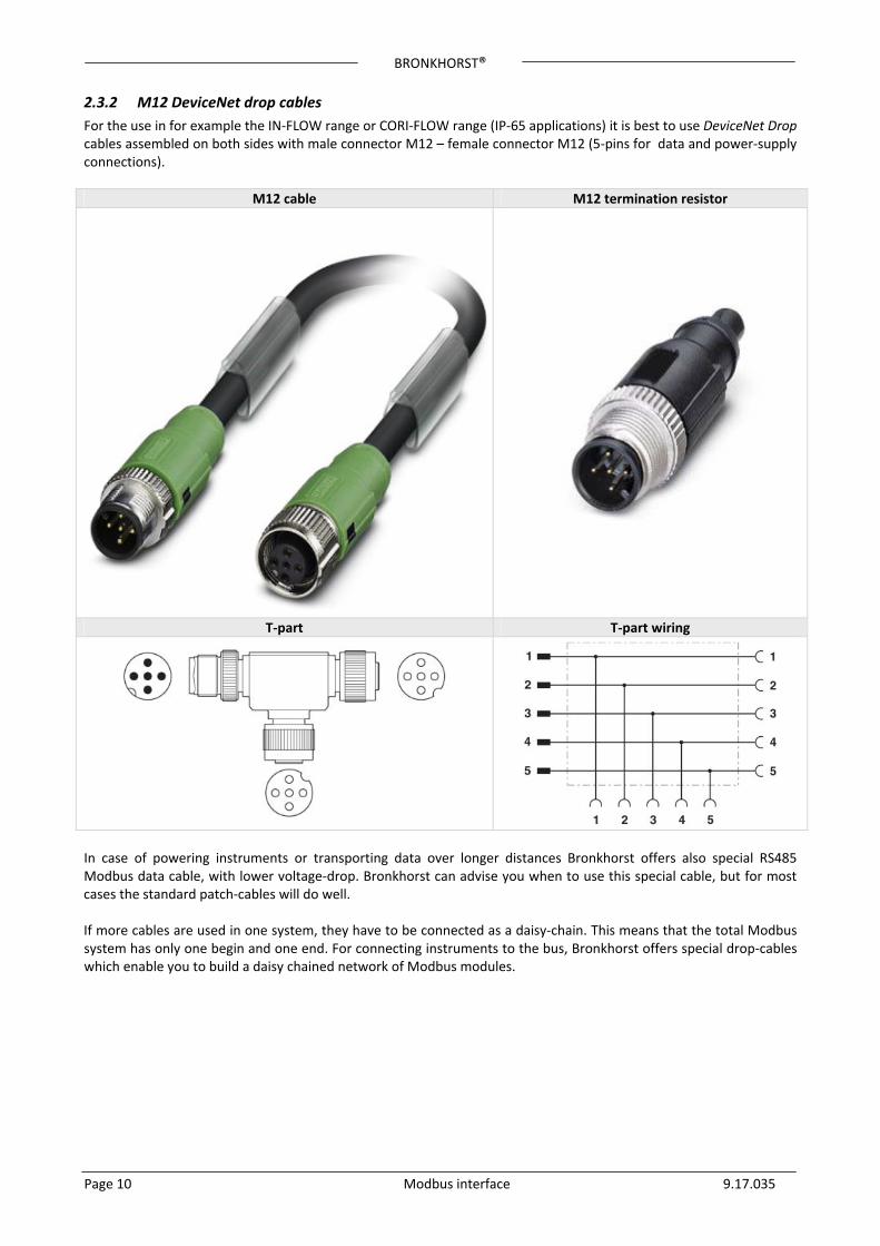
For the use in for example the IN‐FLOW range or CORI‐FLOW range (IP‐65 applications) it is best to use DeviceNet Drop cables assembled on both sides with male connector M12 – female connector M12 (5‐pins for data and power‐supply connections).
M12 cable M12 termination resistor
T‐part T‐part wiring
In case of powering instruments or transporting data over longer distances Bronkhorst offers also special RS485 Modbus data cable, with lower voltage‐drop. Bronkhorst can advise you when to use this special cable, but for most cases the standard patch‐cables will do well. If more cables are used in one system, they have to be connected as a daisy‐chain. This means that the total Modbus system has only one begin and one end. For connecting instruments to the bus, Bronkhorst offers special drop‐cables which enable you to build a daisy chained network of Modbus modules.
Page 10 Modbus interface 9.17.035
BRONKHORST®
Page 11 Modbus interface 9.17.035
2.4 Termination For best quality of data transfer Modbus should be terminated correctly.
2.4.1 Termination resistors
A resistor is added in parallel with the receiver’s “A” and “B” lines in order to match the data line characteristic impedance specified by the cable manufacturer (120 Ω is a common value). This value describes the intrinsic impedance of the transmission line and is not a function of the line length. A terminating resistor of less than 90 Ω should not be used. Termination resistors should be placed only at the extreme ends of the data line (see Termination schematics resistors RT1 and RT2), and no more than two terminations should be placed in any system that does not use repeaters.
2.4.2 Biasing resistors
When an RS‐485 network is in an idle state, all nodes are in listen (receive) mode. Under this condition there are no active drivers on the network. All drivers are tri‐stated. Without anything driving the network, the state of the line is unknown. If the voltage level at the receiver’s A and B inputs is less than ±200 mV the logic level at the output of the receivers will be the value of the last bit received. In order to maintain the proper idle voltage state, bias resistors must be applied to force the data lines to the idle condition. Bias resistors are nothing more than a pull‐up resistor (RB1) on the data D1 Modbus (B/B') line and a pull‐down (to ground) on the data D0 Modbus (A/A') line. The “Termination schematic” illustrates the placement of bias resistors on a transceiver. The value of the bias resistors is dependent on termination and number of nodes in the system. The goal is to generate enough DC bias current in the network to maintain a minimum of 200 mV between the B and A data line. Consider the following example of bias resistor calculation. Ideal situation: Termination resistors: 120 Ohm Receiver resistance: omitted Bias supply voltage: 5Vdc Wanted situation is a minimum of 200mV between A and B lines and a common mode voltage of 2.5V. Minimum current therefore: 200mV / 60 Ohm = 3.33mA Total maximum bias resistor value is (5V – 0.2V)/3.33mA = 1440 Ohm. The maximum value of each biasing resistor: 720 Ohm. Situation with 127 nodes: Termination resistors: 120 Ohm Receiver resistance: 12 KOhm Number of instruments: 127 Bias supply voltage: 5Vdc Wanted situation is a minimum of 200mV between A and B lines and a common mode voltage of 2.5V. Total termination resistance: 120 // 120 // 12000* 127 = 120 // 120 // 94.5 = 36.7 Ohm Minimum current therefore: 200mV / 36.7 Ohm = 5.45mA Total maximum bias resistor value is (5V – 0.2V)/5.45mA = 880 Ohm. The maximum value of each biasing resistors: 440 Ohm. Lower values may be used. (Depending on maximum power consumption of the resistors)
Bronkhorst advices the following resistor values for the following voltages.
Supply voltage termination
Termination resistors
Bias Pull‐up resistor
Bias Pull‐down resistor
+5V 121 Ohm 392 Ohm 392 Ohm
+10V 121 Ohm 1210 Ohm 392 Ohm
+15V 121 Ohm 2210 Ohm 392 Ohm
+24V 121 Ohm 3480 Ohm 392 Ohm
BRONKHORST®
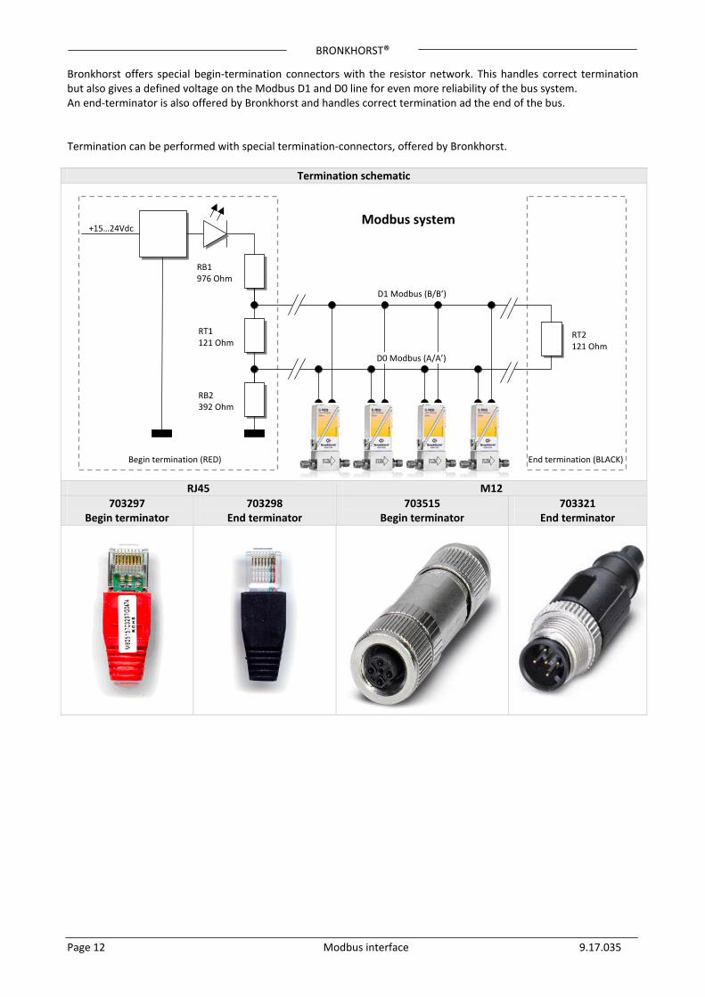
Bronkhorst offers special begin‐termination connectors with the resistor network. This handles correct termination but also gives a defined voltage on the Modbus D1 and D0 line for even more reliability of the bus system. An end‐terminator is also offered by Bronkhorst and handles correct termination ad the end of the bus. Termination can be performed with special termination‐connectors, offered by Bronkhorst.
Termination schematic
RJ45 M12
703297 Begin terminator
703298 End terminator
703515 Begin terminator
703321 End terminator
+15…24Vdc
RB1976 Ohm
RT1121 Ohm
RB2392 Ohm
Modbus system
D1 Modbus (B/B’)
D0 Modbus (A/A’)
RT2121 Ohm
Begin termination (RED) End termination (BLACK)
Page 12 Modbus interface 9.17.035
BRONKHORST®
3 CHANGING SLAVE ADDRESS AND BAUD RATE Default instruments will be delivered to customers on address 1 and with a baud rate of 19200 baud. The slave address and baud rate of the Bronkhorst meter/controller Modbus slave can be changed to fit the instrument in your existing Modbus network. Standard baud rates for Modbus are 9600, 19200 (default) and 38400.
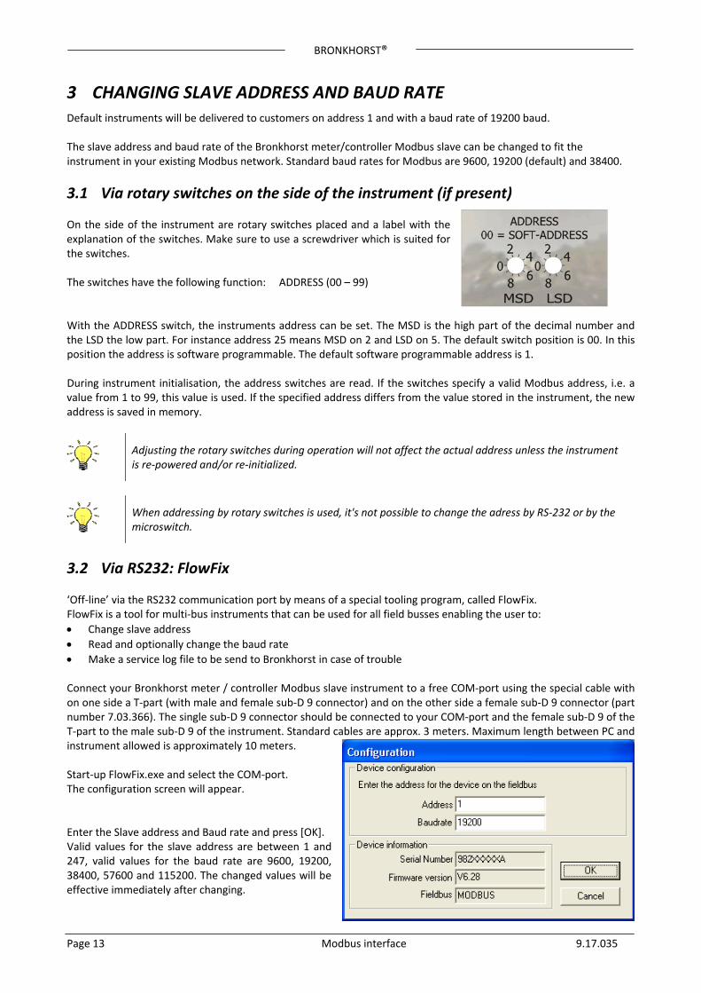
3.1 Via rotary switches on the side of the instrument (if present) On the side of the instrument are rotary switches placed and a label with the explanation of the switches. Make sure to use a screwdriver which is suited for the switches. The switches have the following function: ADDRESS (00 – 99) With the ADDRESS switch, the instruments address can be set. The MSD is the high part of the decimal number and the LSD the low part. For instance address 25 means MSD on 2 and LSD on 5. The default switch position is 00. In this position the address is software programmable. The default software programmable address is 1. During instrument initialisation, the address switches are read. If the switches specify a valid Modbus address, i.e. a value from 1 to 99, this value is used. If the specified address differs from the value stored in the instrument, the new address is saved in memory.
Page 13 Modbus interface 9.17.035
Adjusting the rotary switches during operation will not affect the actual address unless the instrument is re‐powered and/or re‐initialized.
When addressing by rotary switches is used, it's not possible to change the adress by RS‐232 or by the microswitch.
3.2 Via RS232: FlowFix ‘Off‐line’ via the RS232 communication port by means of a special tooling program, called FlowFix. FlowFix is a tool for multi‐bus instruments that can be used for all field busses enabling the user to:
Change slave address
Read and optionally change the baud rate
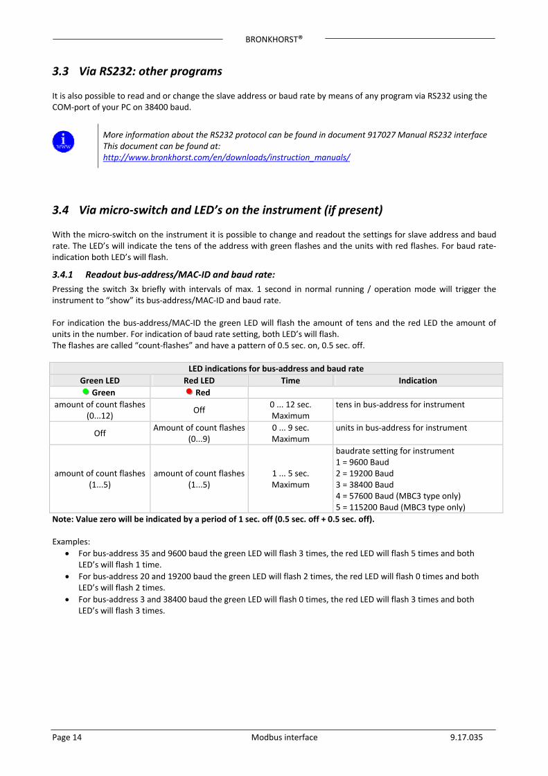
Make a service log file to be send to Bronkhorst in case of trouble Connect your Bronkhorst meter / controller Modbus slave instrument to a free COM‐port using the special cable with on one side a T‐part (with male and female sub‐D 9 connector) and on the other side a female sub‐D 9 connector (part number 7.03.366). The single sub‐D 9 connector should be connected to your COM‐port and the female sub‐D 9 of the T‐part to the male sub‐D 9 of the instrument. Standard cables are approx. 3 meters. Maximum length between PC and instrument allowed is approximately 10 meters. Start‐up FlowFix.exe and select the COM‐port. The configuration screen will appear. Enter the Slave address and Baud rate and press [OK]. Valid values for the slave address are between 1 and 247, valid values for the baud rate are 9600, 19200, 38400, 57600 and 115200. The changed values will be effective immediately after changing.
BRONKHORST®
Page 14 Modbus interface 9.17.035
3.3 Via RS232: other programs It is also possible to read and or change the slave address or baud rate by means of any program via RS232 using the COM‐port of your PC on 38400 baud.
More information about the RS232 protocol can be found in document 917027 Manual RS232 interface This document can be found at: http://www.bronkhorst.com/en/downloads/instruction_manuals/
3.4 Via micro‐switch and LED’s on the instrument (if present) With the micro‐switch on the instrument it is possible to change and readout the settings for slave address and baud rate. The LED’s will indicate the tens of the address with green flashes and the units with red flashes. For baud rate‐indication both LED’s will flash.
3.4.1 Readout bus‐address/MAC‐ID and baud rate:
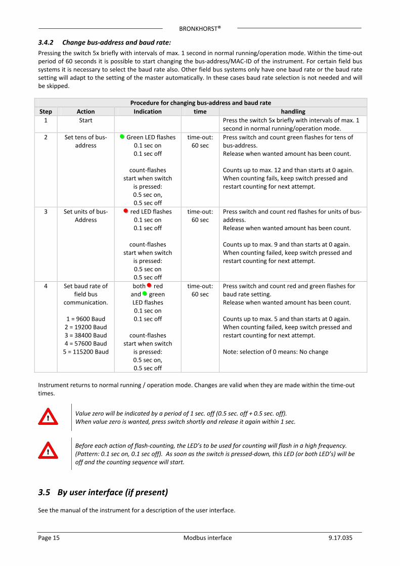
Pressing the switch 3x briefly with intervals of max. 1 second in normal running / operation mode will trigger the instrument to “show” its bus‐address/MAC‐ID and baud rate. For indication the bus‐address/MAC‐ID the green LED will flash the amount of tens and the red LED the amount of units in the number. For indication of baud rate setting, both LED’s will flash. The flashes are called “count‐flashes” and have a pattern of 0.5 sec. on, 0.5 sec. off.
LED indications for bus‐address and baud rate
Green LED Red LED Time Indication
Green Red
amount of count flashes (0...12)
Off 0 ... 12 sec. Maximum
tens in bus‐address for instrument
Off Amount of count flashes
(0...9) 0 ... 9 sec. Maximum
units in bus‐address for instrument
amount of count flashes (1...5)
amount of count flashes(1...5)
1 ... 5 sec. Maximum
baudrate setting for instrument 1 = 9600 Baud 2 = 19200 Baud 3 = 38400 Baud 4 = 57600 Baud (MBC3 type only) 5 = 115200 Baud (MBC3 type only)
Note: Value zero will be indicated by a period of 1 sec. off (0.5 sec. off + 0.5 sec. off). Examples:
For bus‐address 35 and 9600 baud the green LED will flash 3 times, the red LED will flash 5 times and both LED’s will flash 1 time.
For bus‐address 20 and 19200 baud the green LED will flash 2 times, the red LED will flash 0 times and both LED’s will flash 2 times.
For bus‐address 3 and 38400 baud the green LED will flash 0 times, the red LED will flash 3 times and both LED’s will flash 3 times.
BRONKHORST®
Page 15 Modbus interface 9.17.035
3.4.2 Change bus‐address and baud rate:
Pressing the switch 5x briefly with intervals of max. 1 second in normal running/operation mode. Within the time‐out period of 60 seconds it is possible to start changing the bus‐address/MAC‐ID of the instrument. For certain field bus systems it is necessary to select the baud rate also. Other field bus systems only have one baud rate or the baud rate setting will adapt to the setting of the master automatically. In these cases baud rate selection is not needed and will be skipped.
Procedure for changing bus‐address and baud rate
Step Action Indication time handling
1 Start Press the switch 5x briefly with intervals of max. 1 second in normal running/operation mode.
2 Set tens of bus‐ address
Green LED flashes 0.1 sec on 0.1 sec off
count‐flashes
start when switch is pressed: 0.5 sec on, 0.5 sec off
time‐out: 60 sec
Press switch and count green flashes for tens of bus‐address. Release when wanted amount has been count. Counts up to max. 12 and than starts at 0 again. When counting fails, keep switch pressed and restart counting for next attempt.
3 Set units of bus‐ Address
red LED flashes 0.1 sec on 0.1 sec off
count‐flashes
start when switch is pressed: 0.5 sec on 0.5 sec off
time‐out: 60 sec
Press switch and count red flashes for units of bus‐address. Release when wanted amount has been count. Counts up to max. 9 and than starts at 0 again. When counting failed, keep switch pressed and restart counting for next attempt.
4 Set baud rate of field bus
communication.
1 = 9600 Baud 2 = 19200 Baud 3 = 38400 Baud 4 = 57600 Baud 5 = 115200 Baud
both red and green LED flashes 0.1 sec on 0.1 sec off
count‐flashes
start when switch is pressed: 0.5 sec on, 0.5 sec off
time‐out: 60 sec
Press switch and count red and green flashes for baud rate setting. Release when wanted amount has been count. Counts up to max. 5 and than starts at 0 again. When counting failed, keep switch pressed and restart counting for next attempt. Note: selection of 0 means: No change
Instrument returns to normal running / operation mode. Changes are valid when they are made within the time‐out times.
Value zero will be indicated by a period of 1 sec. off (0.5 sec. off + 0.5 sec. off). When value zero is wanted, press switch shortly and release it again within 1 sec.
Before each action of flash‐counting, the LED’s to be used for counting will flash in a high frequency. (Pattern: 0.1 sec on, 0.1 sec off). As soon as the switch is pressed‐down, this LED (or both LED’s) will be off and the counting sequence will start.
3.5 By user interface (if present) See the manual of the instrument for a description of the user interface.
BRONKHORST®
Page 16 Modbus interface 9.17.035
4 FUNCTIONAL DESCRIPTION
4.1 General The information found here is the basic information needed for the installation of a Modbus system.
The implementation of the Modbus interface is based on the following standards: [1] Modbus_Application_Protocol_V1_1b.pdf December 28, 2006 [2] Modbus_over_serial_line_V1_02.pdf December 20, 2006
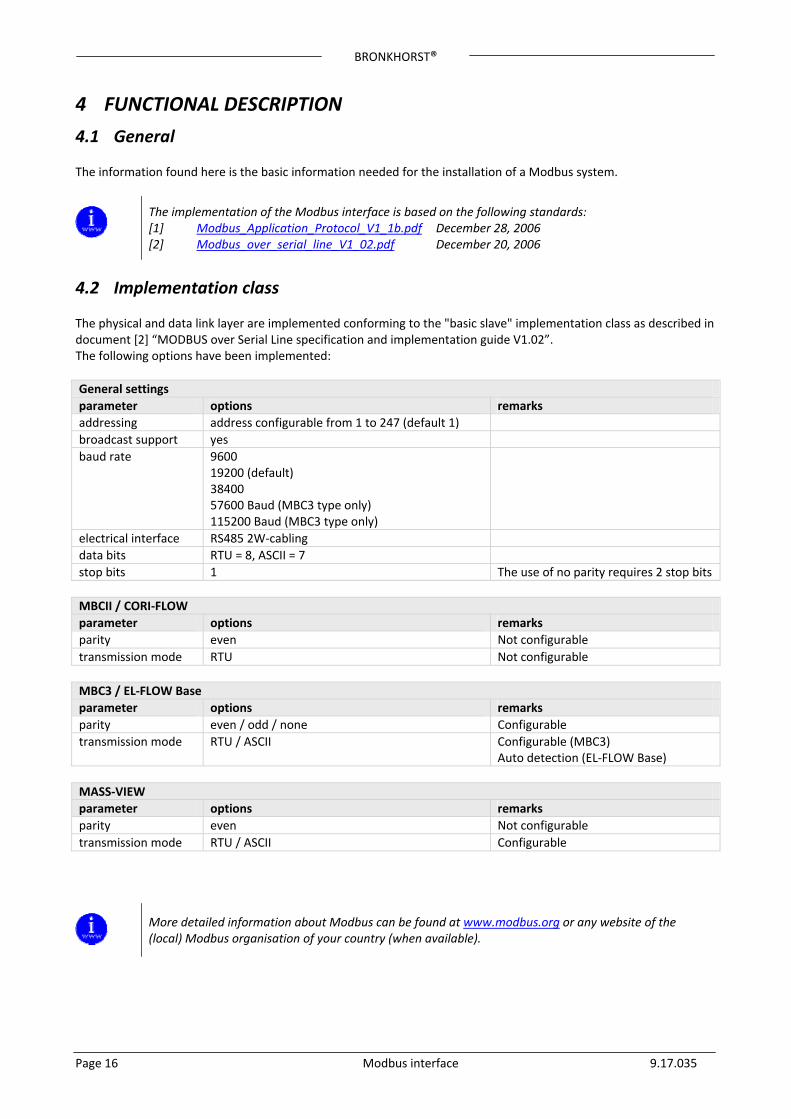
4.2 Implementation class The physical and data link layer are implemented conforming to the "basic slave" implementation class as described in document [2] “MODBUS over Serial Line specification and implementation guide V1.02”. The following options have been implemented:
General settings
parameter options remarks
addressing address configurable from 1 to 247 (default 1)
broadcast support yes
baud rate 9600 19200 (default) 38400 57600 Baud (MBC3 type only) 115200 Baud (MBC3 type only)
electrical interface RS485 2W‐cabling
data bits RTU = 8, ASCII = 7
stop bits 1 The use of no parity requires 2 stop bits
MBCII / CORI‐FLOW
parameter options remarks
parity even Not configurable
transmission mode RTU Not configurable
MBC3 / EL‐FLOW Base
parameter options remarks
parity even / odd / none Configurable
transmission mode RTU / ASCII Configurable (MBC3) Auto detection (EL‐FLOW Base)
MASS‐VIEW
parameter options remarks
parity even Not configurable
transmission mode RTU / ASCII Configurable
More detailed information about Modbus can be found at www.modbus.org or any website of the (local) Modbus organisation of your country (when available).
BRONKHORST®
Page 17 Modbus interface 9.17.035
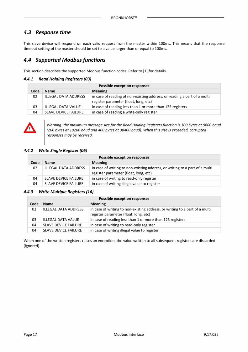
4.3 Response time This slave device will respond on each valid request from the master within 100ms. This means that the response timeout setting of the master should be set to a value larger than or equal to 100ms.
4.4 Supported Modbus functions This section describes the supported Modbus function codes. Refer to [1] for details.
4.4.1 Read Holding Registers (03)
Possible exception responses
Code Name Meaning
02 ILLEGAL DATA ADDRESS in case of reading of non‐existing address, or reading a part of a multi register parameter (float, long, etc)
03 ILLEGAL DATA VALUE in case of reading less than 1 or more than 125 registers
04 SLAVE DEVICE FAILURE in case of reading a write‐only register
Warning: the maximum message size for the Read Holding Registers function is 100 bytes at 9600 baud (200 bytes at 19200 baud and 400 bytes at 38400 baud). When this size is exceeded, corrupted responses may be received.
4.4.2 Write Single Register (06)
Possible exception responses
Code Name Meaning
02 ILLEGAL DATA ADDRESS in case of writing to non‐existing address, or writing to a part of a multi register parameter (float, long, etc)
04 SLAVE DEVICE FAILURE in case of writing to read‐only register
04 SLAVE DEVICE FAILURE in case of writing illegal value to register
4.4.3 Write Multiple Registers (16)
Possible exception responses
Code Name Meaning
02 ILLEGAL DATA ADDRESS in case of writing to non‐existing address, or writing to a part of a multi register parameter (float, long, etc)
03 ILLEGAL DATA VALUE in case of reading less than 1 or more than 123 registers
04 SLAVE DEVICE FAILURE in case of writing to read‐only register
04 SLAVE DEVICE FAILURE in case of writing illegal value to register
When one of the written registers raises an exception, the value written to all subsequent registers are discarded (ignored).
BRONKHORST®
Page 18 Modbus interface 9.17.035
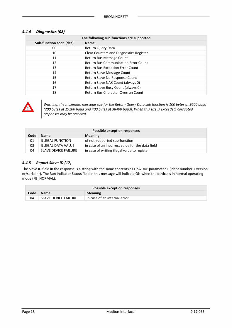
4.4.4 Diagnostics (08)
The following sub‐functions are supported
Sub‐function code (dec) Name
00 Return Query Data
10 Clear Counters and Diagnostics Register
11 Return Bus Message Count
12 Return Bus Communication Error Count
13 Return Bus Exception Error Count
14 Return Slave Message Count
15 Return Slave No Response Count
16 Return Slave NAK Count (always 0)
17 Return Slave Busy Count (always 0)
18 Return Bus Character Overrun Count
Warning: the maximum message size for the Return Query Data sub function is 100 bytes at 9600 baud (200 bytes at 19200 baud and 400 bytes at 38400 baud). When this size is exceeded, corrupted responses may be received.
Possible exception responses
Code Name Meaning
01 ILLEGAL FUNCTION of not‐supported sub‐function
03 ILLEGAL DATA VALUE in case of an incorrect value for the data field
04 SLAVE DEVICE FAILURE in case of writing illegal value to register
4.4.5 Report Slave ID (17)
The Slave ID field in the response is a string with the same contents as FlowDDE parameter 1 (ident number + version nr/serial nr). The Run Indicator Status field in this message will indicate ON when the device is in normal operating mode (FB_NORMAL).
Possible exception responses
Code Name Meaning
04 SLAVE DEVICE FAILURE in case of an internal error
BRONKHORST®
Page 19 Modbus interface 9.17.035
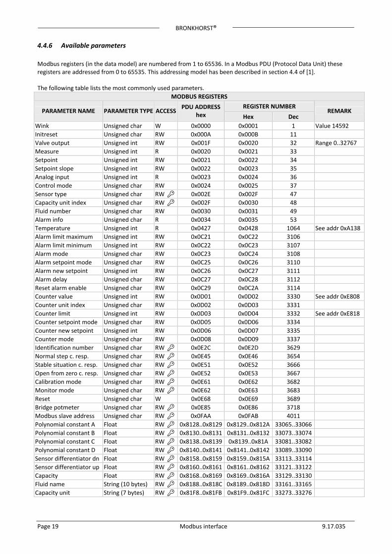
4.4.6 Available parameters
Modbus registers (in the data model) are numbered from 1 to 65536. In a Modbus PDU (Protocol Data Unit) these registers are addressed from 0 to 65535. This addressing model has been described in section 4.4 of [1]. The following table lists the most commonly used parameters.
MODBUS REGISTERS
REGISTER NUMBER PARAMETER NAME PARAMETER TYPE ACCESS
PDU ADDRESShex Hex Dec
REMARK
Wink Unsigned char W 0x0000 0x0001 1 Value 14592
Initreset Unsigned char RW 0x000A 0x000B 11
Valve output Unsigned int RW 0x001F 0x0020 32 Range 0..32767
Measure Unsigned int R 0x0020 0x0021 33
Setpoint Unsigned int RW 0x0021 0x0022 34
Setpoint slope Unsigned int RW 0x0022 0x0023 35
Analog input Unsigned int R 0x0023 0x0024 36
Control mode Unsigned char RW 0x0024 0x0025 37
Sensor type Unsigned char RW 0x002E 0x002F 47
Capacity unit index Unsigned char RW 0x002F 0x0030 48
Fluid number Unsigned char RW 0x0030 0x0031 49
Alarm info Unsigned char R 0x0034 0x0035 53
Temperature Unsigned int R 0x0427 0x0428 1064 See addr 0xA138
Alarm limit maximum Unsigned int RW 0x0C21 0x0C22 3106
Alarm limit minimum Unsigned int RW 0x0C22 0x0C23 3107
Alarm mode Unsigned char RW 0x0C23 0x0C24 3108
Alarm setpoint mode Unsigned char RW 0x0C25 0x0C26 3110
Alarm new setpoint Unsigned int RW 0x0C26 0x0C27 3111
Alarm delay Unsigned char RW 0x0C27 0x0C28 3112
Reset alarm enable Unsigned char RW 0x0C29 0x0C2A 3114
Counter value Unsigned int RW 0x0D01 0x0D02 3330 See addr 0xE808
Counter unit index Unsigned char RW 0x0D02 0x0D03 3331
Counter limit Unsigned int RW 0x0D03 0x0D04 3332 See addr 0xE818
Counter setpoint mode Unsigned char RW 0x0D05 0x0D06 3334
Counter new setpoint Unsigned int RW 0x0D06 0x0D07 3335
Counter mode Unsigned char RW 0x0D08 0x0D09 3337
Identification number Unsigned char RW 0x0E2C 0x0E2D 3629
Normal step c. resp. Unsigned char RW 0x0E45 0x0E46 3654
Stable situation c. resp. Unsigned char RW 0x0E51 0x0E52 3666
Open from zero c. resp. Unsigned char RW 0x0E52 0x0E53 3667
Calibration mode Unsigned char RW 0x0E61 0x0E62 3682
Monitor mode Unsigned char RW 0x0E62 0x0E63 3683
Reset Unsigned char W 0x0E68 0x0E69 3689
Bridge potmeter Unsigned char RW 0x0E85 0x0E86 3718
Modbus slave address Unsigned char RW 0x0FAA 0x0FAB 4011
Polynomial constant A Float RW 0x8128..0x8129 0x8129..0x812A 33065..33066
Polynomial constant B Float RW 0x8130..0x8131 0x8131..0x8132 33073..33074
Polynomial constant C Float RW 0x8138..0x8139 0x8139..0x81A 33081..33082
Polynomial constant D Float RW 0x8140..0x8141 0x8141..0x8142 33089..33090
Sensor differentiator dn Float RW 0x8158..0x8159 0x8159..0x815A 33113..33114
Sensor differentiator up Float RW 0x8160..0x8161 0x8161..0x8162 33121..33122
Capacity Float RW 0x8168..0x8169 0x8169..0x816A 33129..33130
Fluid name String (10 bytes) RW 0x8188..0x818C 0x8189..0x818D 33161..33165
Capacity unit String (7 bytes) RW 0x81F8..0x81FB 0x81F9..0x81FC 33273..33276
BRONKHORST®
Page 20 Modbus interface 9.17.035
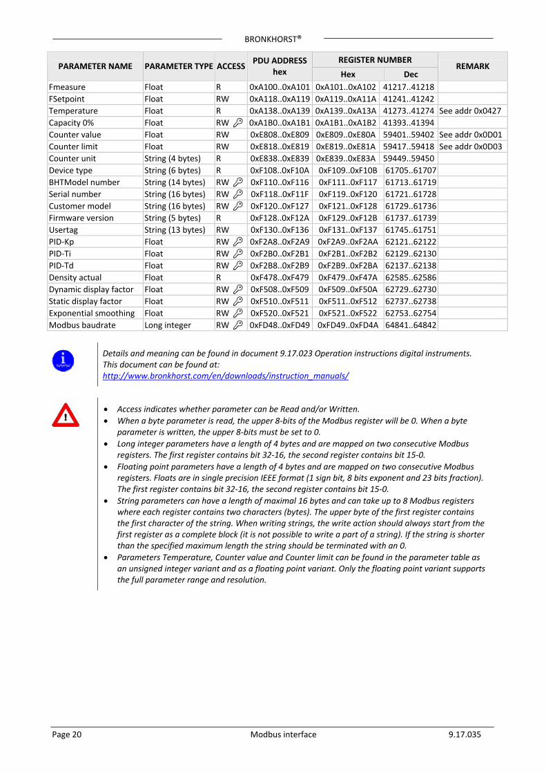
REGISTER NUMBER PARAMETER NAME PARAMETER TYPE ACCESS
PDU ADDRESShex Hex Dec
REMARK
Fmeasure Float R 0xA100..0xA101 0xA101..0xA102 41217..41218
FSetpoint Float RW 0xA118..0xA119 0xA119..0xA11A 41241..41242
Temperature Float R 0xA138..0xA139 0xA139..0xA13A 41273..41274 See addr 0x0427
Capacity 0% Float RW 0xA1B0..0xA1B1 0xA1B1..0xA1B2 41393..41394
Counter value Float RW 0xE808..0xE809 0xE809..0xE80A 59401..59402 See addr 0x0D01
Counter limit Float RW 0xE818..0xE819 0xE819..0xE81A 59417..59418 See addr 0x0D03
Counter unit String (4 bytes) R 0xE838..0xE839 0xE839..0xE83A 59449..59450
Device type String (6 bytes) R 0xF108..0xF10A 0xF109..0xF10B 61705..61707
BHTModel number String (14 bytes) RW 0xF110..0xF116 0xF111..0xF117 61713..61719
Serial number String (16 bytes) RW 0xF118..0xF11F 0xF119..0xF120 61721..61728
Customer model String (16 bytes) RW 0xF120..0xF127 0xF121..0xF128 61729..61736
Firmware version String (5 bytes) R 0xF128..0xF12A 0xF129..0xF12B 61737..61739
Usertag String (13 bytes) RW 0xF130..0xF136 0xF131..0xF137 61745..61751
PID‐Kp Float RW 0xF2A8..0xF2A9 0xF2A9..0xF2AA 62121..62122
PID‐Ti Float RW 0xF2B0..0xF2B1 0xF2B1..0xF2B2 62129..62130
PID‐Td Float RW 0xF2B8..0xF2B9 0xF2B9..0xF2BA 62137..62138
Density actual Float R 0xF478..0xF479 0xF479..0xF47A 62585..62586
Dynamic display factor Float RW 0xF508..0xF509 0xF509..0xF50A 62729..62730
Static display factor Float RW 0xF510..0xF511 0xF511..0xF512 62737..62738
Exponential smoothing Float RW 0xF520..0xF521 0xF521..0xF522 62753..62754
Modbus baudrate Long integer RW 0xFD48..0xFD49 0xFD49..0xFD4A 64841..64842
Details and meaning can be found in document 9.17.023 Operation instructions digital instruments. This document can be found at: http://www.bronkhorst.com/en/downloads/instruction_manuals/
Access indicates whether parameter can be Read and/or Written.
When a byte parameter is read, the upper 8‐bits of the Modbus register will be 0. When a byte parameter is written, the upper 8‐bits must be set to 0.
Long integer parameters have a length of 4 bytes and are mapped on two consecutive Modbus registers. The first register contains bit 32‐16, the second register contains bit 15‐0.
Floating point parameters have a length of 4 bytes and are mapped on two consecutive Modbus registers. Floats are in single precision IEEE format (1 sign bit, 8 bits exponent and 23 bits fraction). The first register contains bit 32‐16, the second register contains bit 15‐0.
String parameters can have a length of maximal 16 bytes and can take up to 8 Modbus registers where each register contains two characters (bytes). The upper byte of the first register contains the first character of the string. When writing strings, the write action should always start from the first register as a complete block (it is not possible to write a part of a string). If the string is shorter than the specified maximum length the string should be terminated with an 0.
Parameters Temperature, Counter value and Counter limit can be found in the parameter table as an unsigned integer variant and as a floating point variant. Only the floating point variant supports the full parameter range and resolution.
BRONKHORST®
5 TROUBLESHOOTING
5.1 Visual diagnostics LED indications (if present) can be very useful in case of problems with the instrument. The green LED is normally used for instrument status indication, like normal operation or special function mode. The red LED will burn continuously in case of a hardware failure. During normal operation, the red LED is switched on during frame reception or sending on the Modbus interface.
More information can be found in document 9.17.023 Operation instructions digital instruments. This document can be found at: http://www.bronkhorst.com/en/downloads/instruction_manuals/
Page 21 Modbus interface 9.17.035
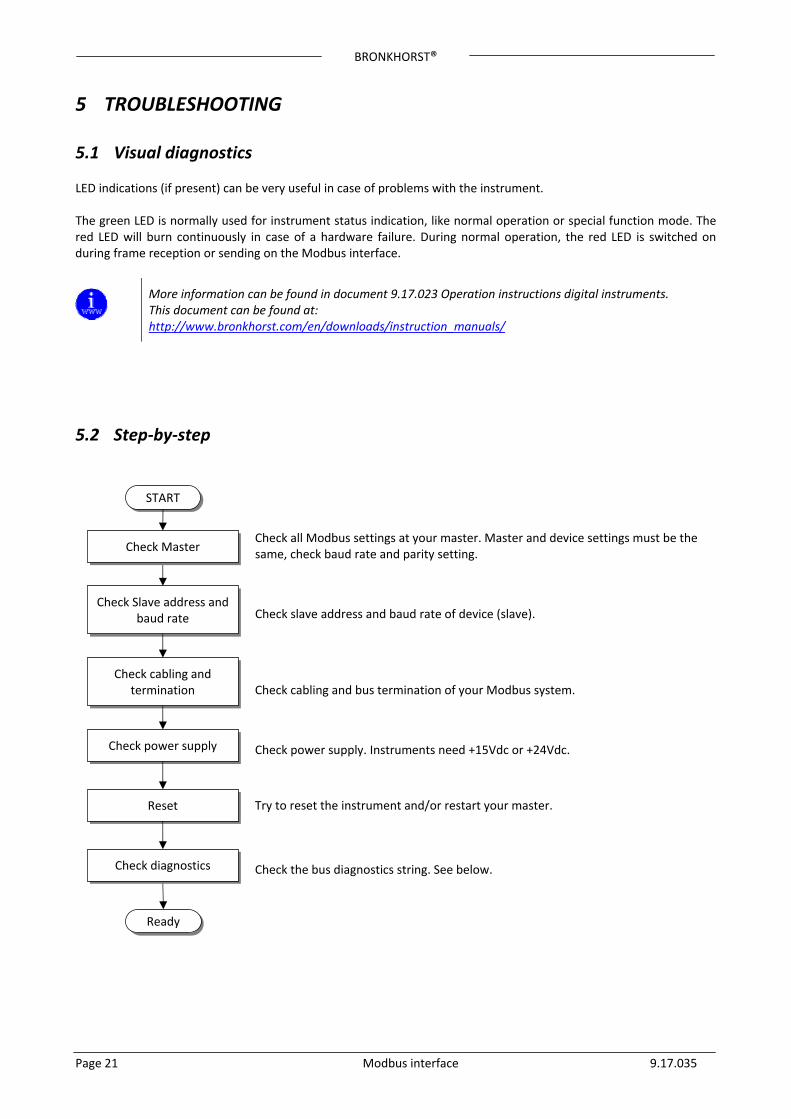
5.2 Step‐by‐step
Check Slave address and baud rate
Check all Modbus settings at your master. Master and device settings must be the same, check baud rate and parity setting.
Check slave address and baud rate of device (slave).
Check cabling and termination Check cabling and bus termination of your Modbus system.
Check power supply Check power supply. Instruments need +15Vdc or +24Vdc.
Reset Try to reset the instrument and/or restart your master.
Check diagnostics Check the bus diagnostics string. See below.
Check Master
Ready
START
BRONKHORST®
Page 22 Modbus interface 9.17.035
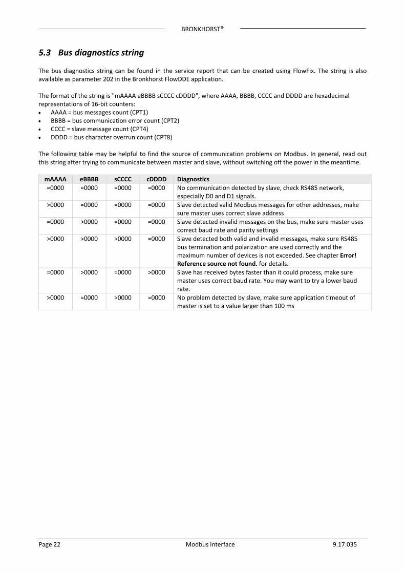
5.3 Bus diagnostics string The bus diagnostics string can be found in the service report that can be created using FlowFix. The string is also available as parameter 202 in the Bronkhorst FlowDDE application. The format of the string is "mAAAA eBBBB sCCCC cDDDD", where AAAA, BBBB, CCCC and DDDD are hexadecimal representations of 16‐bit counters: AAAA = bus messages count (CPT1) BBBB = bus communication error count (CPT2) CCCC = slave message count (CPT4) DDDD = bus character overrun count (CPT8) The following table may be helpful to find the source of communication problems on Modbus. In general, read out this string after trying to communicate between master and slave, without switching off the power in the meantime.
mAAAA eBBBB sCCCC cDDDD Diagnostics
=0000 =0000 =0000 =0000 No communication detected by slave, check RS485 network, especially D0 and D1 signals.
>0000 =0000 =0000 =0000 Slave detected valid Modbus messages for other addresses, make sure master uses correct slave address
=0000 >0000 =0000 =0000 Slave detected invalid messages on the bus, make sure master uses correct baud rate and parity settings
>0000 >0000 >0000 =0000 Slave detected both valid and invalid messages, make sure RS485 bus termination and polarization are used correctly and the maximum number of devices is not exceeded. See chapter Error! Reference source not found. for details.
=0000 >0000 =0000 >0000 Slave has received bytes faster than it could process, make sure master uses correct baud rate. You may want to try a lower baud rate.
>0000 =0000 >0000 =0000 No problem detected by slave, make sure application timeout of master is set to a value larger than 100 ms

BRONKHORST®
Page 23 Modbus interface 9.17.035
6 SERVICE For current information on Bronkhorst and service addresses please visit our website:
http://www.bronkhorst.com
Do you have any questions about our products? Our Sales Department will gladly assist you selecting the right product for your application. Contact sales by e‐mail:
For after‐sales questions, our Customer Service Department is available with help and guidance. To contact CSD by e‐mail:
No matter the time zone, our experts within the Support Group are available to answer your request immediately or ensure appropriate further action. Our experts can be reached at:
+31 573 45 88 39